
PGF64SA - Cooker SMEG - Free user manual and instructions
Find the device manual for free PGF64SA SMEG in PDF.
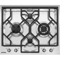


| Product Type | Gas Cooker |
| Brand | Smeg |
| Model | PGF64SA |
| Dimensions (HxWxD) | 85-90 cm x 60 cm x 60 cm |
| Weight | Approximately 55 kg |
| Power Supply | Gas (natural or LPG) + Electric (220-240V, 50/60Hz) |
| Number of Gas Burners | 4 |
| Burner Types | Rapid, semi-rapid, auxiliary, and triple-ring wok burner |
| Oven Type | Electric multifunction oven |
| Oven Capacity | Approximately 70 liters |
| Oven Functions | Conventional, grill, fan-assisted, defrosting |
| Grill | Yes, electric grill |
| Cleaning Type | Enamel interior with catalytic panels |
| Safety Features | Flame failure device on all burners, triple-glazed oven door, child lock |
| Control Type | Front knobs with LED indicators |
| Timer | Programmable electronic timer |
| Energy Class | A (oven) |
| Installation | Built-in or freestanding, requires gas connection |
| Spare Parts Availability | Available from Smeg authorized service centers |
| Repairability Index | 7.5/10 (typical for this range) |
Frequently Asked Questions - PGF64SA SMEG
User questions about PGF64SA SMEG
0 question about this device. Answer the ones you know or ask your own.
Ask a new question about this device
Download the instructions for your Cooker in PDF format for free! Find your manual PGF64SA - SMEG and take your electronic device back in hand. On this page are published all the documents necessary for the use of your device. PGF64SA by SMEG.
USER MANUAL PGF64SA SMEG
1.1 General safety instructions 34 1.2 Manufacturer liability 37 1.3 Appliance purpose 38 1.4 Identification plate 38 1.5 This user manual 38 1.6 Disposal 38 1.7 How to read the user manual 39
2 Description 40
2.1 General Description 40 2.2 Symbols 40 2.3 Available accessories 41
3 Use 42
3.1 Instructions 42 3.2 First use 42 3.3 Using the hob 42
4 Cleaning and maintenance 45
4.1 Instructions 45 4.2 Cleaning the appliance 45
5 Installation
5.1 Safety instructions 47 5.2 Positioning in the counter top 47 5.3 Mounting 51 5.4 Gas connection 52 5.5 Adaptation to different types of gas 55 5.6 Electrical connection 60 5.7 Instructions for the installer 61
These instructions apply only to the destination countries listed on the appliance's data plate.
This is a class 3 built-in hob.
We advise you to read this manual carefully, as it contains all the instructions for maintaining the appliance's aesthetic and functional qualities.
For further information on the product: www.smeg.com
1 Instructions
1.1 General safety instructions
Risk of personal injury
- During use the appliance and its accessible parts become very hot. Never touch the heating elements during use.
- Never try to put out a fire or flames with water: turn off the appliance and smother the flames with a fire blanket or other appropriate cover.
- This appliance may be used by children aged at least 8 and by people of reduced physical, sensory or mental capacity, or lacking in experience in the use of electrical appliances, provided that they are supervised or instructed by adults who are responsible for their safety. Children must not play with the appliance.
- Keep children under the age of 8 at a safe distance unless they are constantly supervised.
- Keep children under the age of 8 away from the appliance when it is in use.
Cleaning and maintenance must not be carried out by unsupervised children. Make sure that the flame-spreader crowns are correctly positioned in their seats with their respective burner caps. Be aware of how rapidly the cooking zones heat up. Do not place empty pans on the heat. Danger of overheating. Fats and oils can catch fire if they overheat. Do not leave the appliance unattended while preparing foods containing oils or fats. If fats or oils catch fire, never put water on them. Place the lid on the pan and turn off the relevant cooking zone. Cooking process should always be kept under control. A short cooking process must be continuously surveyed. While cooking do not place metal objects, such as cutlery or dishes on the hob surface as they may overheat. Do not insert pointed metal objects (cutlery or utensils) into the slots in the appliance.
Instructions
- Do not use aerosols in the vicinity of this appliance whilst it is in use.
- Switch off the appliance after use.
- Do not modify this appliance.
- Do not try to repair the appliance yourself or without the intervention of a qualified technician.
- Do not pull the cable to remove the plug.
- If the power supply cable is damaged, contact technical support immediately and they will replace it.
Risk of damaging the appliance
- Do not sit on the appliance.
- Do not use steam jets to clean the appliance.
- Do not obstruct ventilation openings and heat dispersal slots.
- Never leave the appliance unattended during cooking operations where fats or oils could overheat and take fire. Be very careful.
- Never leave objects on the cooking surface.
- Do not use the appliance to heat rooms for any reason.
- Do not spray any spray products near the oven.
- Do not use plastic cookware or containers for cooking. Cooking vessels or griddle plates should be placed inside the perimeter of the hob.
- All pans must have smooth, flat bottoms.
- If any liquid does boil over or spill, remove the excess from the hob. Take care not to spill acid substances such as lemon juice or vinegar on the hob.
- Do not put empty pans or frying pans on switched on cooking zones.
- Do not use rough or abrasive materials or sharp metal scrapers.
- Do not use cleaning products containing chlorine, ammonia or bleach on parts made of steel or that have metallic surface finishes (e.g. anodizing, nickel- or chromium-plating).
- Do not wash the removable components such as the hob grids, flame-spreader crowns and burner caps in a dishwasher.
Installation
- This appliance must not be installed in a boat or caravan.
- This appliance must not be installed on a pedestal.
- Position the appliance into the cabinet cut-out with the help of a second person.
- To prevent any possible overheating, the appliance should not be installed behind a decoration door or a panel.
- Before any operation on the appliance (installation, maintenance, positioning or movement) always wear PPM.
- Before performing any operation on the appliance, switch off the power supply.
- Have qualified personnel carry out installation and assistance interventions according to the standards in force.
- Have the gas connection performed by authorised staff. Installation with a hose must be carried out so that the length of the piping does not exceed 2 metres when fully extended (for steel hoses).
- The hoses should not come into contact with moving parts and should not be crushed in any way.
- If required, use a pressure regulator that complies with current regulations.
- After carrying out any operation, check that the tightening torque of gas connections is between 10 Nm and 15 Nm.
- At the end of the installation, check for any leaks with a soapy solution, never with a flame.
- Have the electrical connection performed by authorized technicians.
- The appliance must be connected to ground in compliance with electrical system safety standards.
- Use cables that withstand a temperature of at least 90°C.
- The tightening torque of the terminal board lead screws must be 1.5 - 2 Nm.
- If it is necessary to replace the power cable, this must only be performed by a qualified technician.
- Before installation, make sure that the local distribution conditions (nature and pressure of the gas) and the adjustment of the appliance are compatible.
Instructions
- The adjustment conditions for this appliance are shown on the gas setting label.
- This appliance is not connected to an exhaust system for combustion products. It must be installed and connected in compliance with the current installation regulations. Special attention should be paid to the relevant requirements as for ventilation.
For this appliance
- Do not obstruct ventilation openings and heat dispersal slots.
- Do not insert pointed metal objects (cutlery or utensils) into the slots in the appliance.
- Do not use the appliance to heat rooms for any reason.
- The appliance is not designed to operate with external timers or with remote-control systems.
1.2 Manufacturer liability
The manufacturer declines all liability for damage to persons or property caused by:
- Use of the appliance other than the one envisaged,
- failure to comply with the instructions in the user manual, • tampering with any part of the appliance, • use of non-original spare parts.

1.3 Appliance purpose
This appliance is intended for cooking food in the home environment. Every other use is considered inappropriate.
1.4 Identification plate
The identification plate bears the technical data, serial number and brand name of the appliance. Do not remove the identification plate for any reason.
1.5 This user manual
This user manual is an integral part of the appliance and must therefore be kept in its entirety and within the user's reach for the whole working life of the appliance.
Read this user manual carefully before using the appliance.
1.6 Disposal

This appliance must be disposed of separately from other waste (Directives
2002/95/EC, 2002/96/EC, 2003/108/EC). The appliance does not contain substances in quantities sufficient to be considered hazardous to health and the environment, in accordance with current European directives.
To dispose of the appliance:
- Cut the power supply cable and remove it along with the plug.

Power voltage Danger of electrocution
- Disconnect the mains power supply.
- Unplug the appliance.
- Deliver the appliance to the appropriate recycling centre for electrical and electronic equipment waste, or return it to the retailer when purchasing an equivalent product, on a one for one basis.
Instructions
Our appliances are packaged in non-polluting and recyclable materials.
- Deliver the packing materials to the appropriate recycling centre.

Plastic packaging Danger of suffocation
- Do not leave the packaging or any part of it unattended.
- Do not let children play with the plastic bags.
1.7 How to read the user manual
This user manual uses the following reading conventions:
Instructions

General information on this user manual, on safety and final disposal.
Description

Description of the appliance and its accessories.
Use
Information on the use of the appliance and its accessories.
Cleaning and maintenance

Information for proper cleaning and maintenance of the appliance.
Installation

Information for the qualified technician: Installation, operation and inspection.

Safety instructions
Information

Advice
- Sequence of instructions for use.
- Standalone instruction.

2 Description
2.1 General Description

- Control panel
- Auxiliary Burner (AUX)
- Rapid burner reduced (RR)
- Ultra-rapid triple crown burner (UR3)
- Right grid
- Left grid
2.2 Symbols
Cooking zones

Front
Rear

Centre right
Centre left
Burner knobs
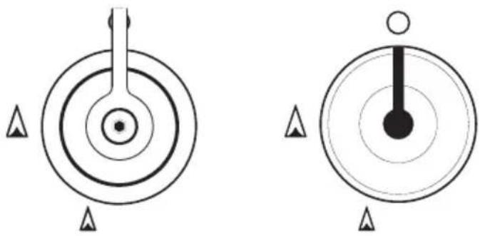
Used for lighting and adjusting the hob burners. Press and turn the knobs anti-clockwise to light the relative burners. Turn the knobs to the zone between the maximum and minimum
setting to adjust the flame. Return the knobs to the position to turn off the burners.
2.3 Available accessories
Raised pan stand
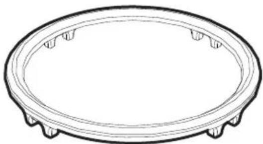
To prevent any damage to the work surface, a raised pan stand is available to be placed under the pans when they exceed the diameters listed in the table "Diameters of the containers", paragraph 3.3 "Use of the top".
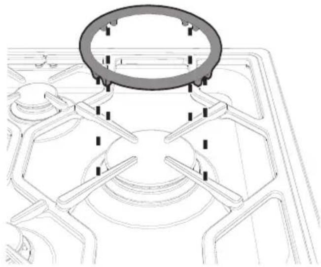
The ring must be placed under the hob grid as shown in the picture above.
In any case, pans with a diameter greater than 28 cm must be used solely on the Ultra-rapid burner (UR3).
This ring can also be used with woks.
3 Use
3.1 Instructions

Improper use Danger of burns
- Make sure that the flame-spreader crowns are correctly positioned in their seats with their respective burner caps.
- Oils and fats could catch fire if overheated. Be very careful.
- Do not leave the appliance unattended during cooking operations where fats or oils could be released.
- Do not spray any spray product near the appliance.
- Do not touch the appliance's heating elements when it is running. Leave them to cool before cleaning.
- Keep children under the age of 8 away from the appliance when it is in use.

Improper use Risk of damage to surfaces
- Do not use aluminium foil to cover the burners or hob body.
- Cookware should be placed inside the perimeter of the hob.
- All pans must have smooth, flat bottoms.
- If any liquid does boil over or spill, remove the excess from the hob.
3.2 First use
- Remove any protective film from the outside or inside of the appliance, including accessories.
- Remove any labels (apart from the technical data plate) from accessories.
- Remove and wash all the appliance's accessories (see 4 Cleaning and maintenance).
3.3 Using the hob
All the appliance's control and monitoring devices are located together on the front panel. The appliance is equipped with an electronic ignition device. Simply press the knob and turn it counterclockwise to the maximum flame symbol, until the burner ignites. If the burner does not light in the first 15 seconds, turn the knob to and wait 60 seconds before trying again. After lighting, keep the knob pressed in for a few seconds to allow the thermocouple to heat up. The burner may go out when the knob is released: In this case, the thermocouple has not heated up sufficiently. Wait a few moments and repeat the operation. Keep the knob pressed in longer.
In case of an accidental switching off, a safety device will be tripped, cutting off the gas supply, even if the gas cock is open. Return the knob to and wait at least 60 seconds before lighting it again.
Positioning the pan stands
The pan stands are provided unassembled on the hob. To install the grids correctly, follow the instructions as shown in the figure.

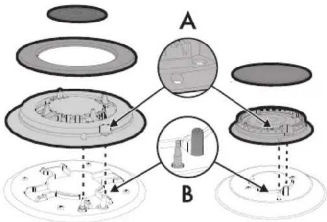
Correct positioning of the flame-spreader crowns and burner caps
Before lighting the hob burners, check that the flame-spreader crowns are correctly in place with their respective burner caps, making sure that the holes (A) in the burner are aligned with the igniters and thermocouples (B).
Practical tips for using the hob
For better burner efficiency and to minimise gas consumption, use pans with lids and of suitable size for the burner, so that the flames do not reach up the sides of the pan. Once the contents come to the boil, turn down the flame far enough to ensure that the liquid does not boil over.

Cookware diameters:
- AUX: 12 - 16 cm.
- RR: 18 - 24 cm.
- UR3: 22 - 26 cm.
Cookware diameters with raised pan stand
- AUX: 16 - 26 cm.
- RR: 24 - 28 cm.
- UR3: 26 - 34 cm.
To prevent burns or damage to the hob or the counter top during cooking, all cookware or griddles must be placed inside the perimeter of the hob.


Always check that the control knobs are in the (off) position when you finish using the appliance.
Limitations on griddle use
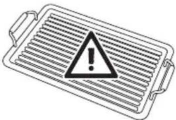
A few precautions are necessary if you wish to use a griddle:
- The griddles should not exceed the perimeter of the hob.
- Aluminium griddles with Teflon anti-stick coating should be pre-heated for a maximum of 5 minutes in order to avoid damage to the appliance and the Teflon coating. After pre-heating, place the foodstuffs on the griddle to cook them; do not exceed 40 minutes of total use for the griddle.
- Do not use griddles or plates to cook or heat food on the ultra-rapid burner (UR3).
- If one of the burners close to the wooden rear wall is an ultra-rapid burner (UR3), leave a gap of 160 mm between this wall and the edge of the griddle;
- Do not allow the burner flames to extend beyond the edge of the griddle;
- Leave a gap of at least 160 mm between the edge of the griddle and the side wall;
- Do not place the griddle over more than one burner at the same time;
- Never use the griddle for more than 40 minutes.
4 Cleaning and maintenance
4.1 Instructions

Improper use Risk of damage to surfaces
- Do not use steam jets to clean the appliance.
- Do not use cleaning products containing chlorine, ammonia or bleach on parts made of steel or that have metallic surface finishes (e.g. anodizing, nickel- or chromium-plating).
- Do not use rough or abrasive materials or sharp metal scrapers.
- Do not wash the removable components such as the hob grids, flame-spreader crowns and burner caps in a dishwasher.
4.2 Cleaning the appliance
To keep the surfaces in good condition, they should be cleaned regularly after use. Let them cool first.
Ordinary daily cleaning
Always use specific products only that do not contain abrasives or chlorine-based acids.
Pour the product onto a damp cloth and wipe the surface, rinse thoroughly and dry with a soft cloth or a microfibre cloth.
Food stains or residues
Do not use steel sponges and sharp scrapers, as they will damage the surfaces.
Use normal, non-abrasive products and a wooden or plastic tool, if necessary. Rinse thoroughly and dry with a soft cloth or a microfibre cloth.
Cooking hob grids
Remove the grids and clean them in lukewarm water and non-abrasive detergent. Make sure to remove any encrustations. Dry them thoroughly and return them to the hob.

The continuous contact between the grids and the flame can cause modifications to the enamel over time in those parts exposed to heat. This is a completely natural phenomenon which has no effect on the operation of this component.
Cleaning and maintenance
Flame-spreader crowns and burner caps
For easier cleaning, the flame-spreader crowns and the burner caps can be removed. Wash them in hot water and non-abrasive detergent. Carefully remove any encrustation, then wait until they are perfectly dry. Refit the flame-spreader crowns making sure that they are correctly positioned in their housings with their respective burner caps.
Knobs

Do not use aggressive products containing alcohol or products for cleaning steel and glass when cleaning the knobs, as these products could cause permanent damage.
The knobs should be cleaned with a soft cloth dampened with warm water, then dried carefully. They can easily be removed by pulling them upwards.

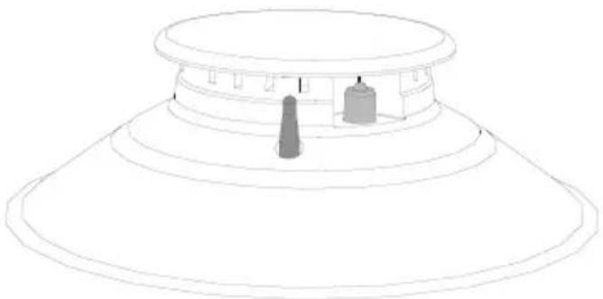
Igniters and thermocouples
For correct operation the igniters and thermocouples must always be perfectly clean. Check them frequently and clean them with a damp cloth if necessary. Remove any dry residues with a wooden toothpick or a needle.
After cleaning, dry the appliance thoroughly to prevent water or detergent drips from interfering with its operation or creating unsightly marks.
5 Installation
5.1 Safety instructions

Heat production during appliance operation Risk of fire
• Make sure that the cabinet material is heat resistant. - Check that the cabinet has the required slots.
Veneers, adhesives or plastic coatings on adjacent furniture should be temperature-resistant ( >90°C ), otherwise they might warp over time.

The minimum clearance between a ventilation hood and the cooking surface must be at least the distance indicated in the ventilation hood installation instructions.
The minimum clearances must also be respected for the edges of the hob on the back as indicated in the mounting illustrations.
5.2 Positioning in the counter top

The following operation requires building and/or carpentry work and must therefore be carried out by a competent tradesman.
Installation can be carried out on various materials such as masonry, metal, solid wood or plastic laminated wood as long as they are heat resistant ( >90°C ).
Fixing to the traditional built-in model support structure
Create an opening with the dimensions shown in the figure in the countertop of the piece of furniture.
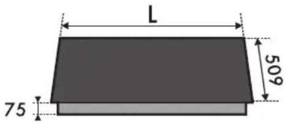
L (mm) X (mm) Y (mm)
617 592 488

A (mm)
B (mm)
C (mm)*
D (mm)
E (mm)
min 150 min 460 min 750 20 - 50 min 50
* If there is a piece of furniture above the hob. In case of hood, refer to the values on the dedicated manual.
Installation
To prevent leakage of liquid between the frame of the hob and the work surface, carefully put the insulating seal provided in position before assembly.
- Refer to the dimensions in the figure, bearing in mind that the front and rear long sides must brush against the hole.
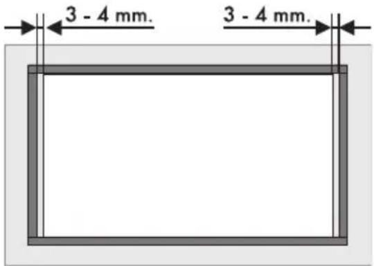
- Make the seal stick to the edge around the hole cut in the worktop, using a slight pressure; front and rear sides of the seal must brush against the hole.


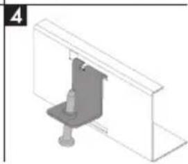

- Place the hob on the insulating seal and fix it to the supporting structure using the supplied screws and fastening brackets (A) so that the hob is perfectly level.
- Carefully trim the surplus away from the edge (B) beyond the seal.
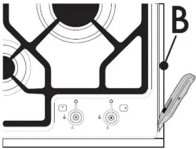

The brackets should be placed only after the hob has been laid on the seal.
Fixing to the flush built-in model support structure
Create an opening with the dimensions shown in the figure in the countertop of the piece of furniture.

L (mm) X (mm) Y (mm)
620 592 488

| L (mm) | X (mm) | Y (mm) | G (mm) | H (mm) |
| 620 59 | 2 488 62 | 1 513 |

A (mm) B (mm) C (mm)* D (mm) E (mm)
min 150 min 460 min 750 20 - 40 min 50
*If there is a piece of furniture above the hob. In case of hood, refer to the values on the dedicated manual.


This kind of built-in application needs a milling on the hob top of 3 mm in depth (detail "B" in the picture above).
Before positioning the appliance, place the supplied seal (C) on the milling.

After these operations, secure the appliance through the supplied special brackets (A) to get a perfect level, according to the instructions in the picture.


The brackets should be placed only after the hob has been laid on the seal.
- If necessary, do not fix the hob using silicone as this would make it impossible to remove the hob without damaging it.
- If a laminated top is used, lay a film of anti-infiltration primer on the milled surface.
Overall dimensions: gas and electrical connection location (measurements in mm)
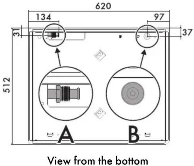
A Gas pipe connection B Electrical connection

Right view
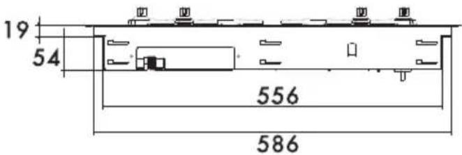
Rear view
5.3 Mounting
Over built-in oven unit
The clearance between the hob and the kitchen furniture or other installed appliances must be enough to ensure sufficient ventilation and air discharge.
If installed above an oven, a space must be left between the bottom of the hob and the top of the appliance installed below.

opens on bottom

opens on bottom and on rear

If installed on top of an oven, the latter must be equipped with a cooling fan.

opens on rear
Over empty kitchen unit or drawers
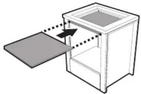
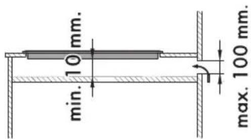
If there are other pieces of furniture (lateral walls, drawers, etc.), dishwashers or fridges under the hob, a double-layer wooden base must be installed at least 10 mm from the bottom of the hob to avoid any accidental contact. It must only be possible to remove the double-layer base using suitable equipment.
opens on bottom

Failure to install the double-layer wooden base exposes the user to possible accidental contact with sharp or hot parts.
5.4 Gas connection

Gas leak Danger of explosion
- After carrying out any operation, check that the tightening torque of gas connections is between 10 Nm and 15 Nm.
- If required, use a pressure regulator that complies with current regulations.
- At the end of the installation, check for any leaks with a soapy solution, never with a flame.
- The hoses should not come into contact with moving parts and should not be crushed in any way.
- The adjustment conditions for this appliance are shown on the gas setting label.
General information
Connection to the gas supply network can be made using a copper hose or a continuous wall steel hose with tapered connection in compliance with the provisions established by the applicable standard.
For supplying it with other types of gas, see chapter "5.5 Adaptation to different types of gas". The gas inlet connection is threaded 1/2 " external gas (ISO 228-1).
Connection with a steel hose
Make the connection to the gas mains using a continuous wall steel hose whose specifications comply with the applicable standard.
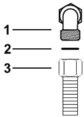
Carefully screw the connector 3 to the gas connector 1 of the appliance, placing the seal 2 between them.
Connection with a steel hose with conical fitting
Make the connection to the gas mains using a continuous wall steel hose whose specifications comply with the applicable standard.
Carefully screw the hose connector 3 to the appliance's gas connector 1 (1/2" thread ISO 228-1), placing the supplied seal 2 between them. Apply insulating material (1/2" ISO 7.1) to the thread of connector 3, then tighten the steel hose 4 to the connector 3.

Connection to LPG
Use a pressure regulator and make the connection on the gas cylinder following the guidelines set out in the standards in force.

The supply pressure must comply with the values indicated in the table "Gas types and Countries".
Room ventilation
The appliance should be installed in rooms that have a permanent air supply in accordance with the standards in force. The room where the appliance is installed must have enough air flow for the regular combustion of gas and the necessary air change in the room itself. The air vents, protected by grilles, must be the right size to comply with current regulations and positioned so that no part of them is obstructed, not even partially.
The room must be kept adequately ventilated in order to eliminate the heat and humidity produced by cooking: In particular, after prolonged use, you are recommended to open a window or to increase the speed of any fans.
Extraction of the combustion products

This appliance is not connected to an exhaust system for combustion products. It must be installed and connected in compliance with the current installation regulations. Special attention should be paid to the relevant requirements as for ventilation.
The combustion products may be extracted by means of hoods connected to a natural draught chimney whose efficiency is certain or via forced extraction. An efficient extraction system requires precision planning by a specialist qualified in this area and must comply with the positions and clearances indicated by the applicable standards.
When the job is complete, the installer must issue a certificate of conformity.
1 Extraction using a hood 2 Extraction without a hood
A Single natural draught chimney B Single chimney with extractor fan C Directly outdoors with wall- or window-mounted extractor fan D Directly outdoors through wall

Air

Combustion products

Extractor fan

Installation

5.5 Adaptation to different types of gas
In case of operation with other types of gas, the burner nozzles must be changed and the minimum flame adjusted on the gas taps.
Changing the nozzles
- Remove the grids from the hob.

- Remove the flame-spreader crowns and relative burner caps.

- Replace the burner nozzles using a 7 mm socket wrench according to the gas to be used (see "Nozzle and burner specification tables").

- Reposition the burners in their respective housings.

The nozzle tightening torque must be no more than 3 Nm.

Installation
Adjusting the minimum setting for natural or town gas
- Light the burner and turn it to the minimum position.
- Remove the knobs by pulling them upwards.
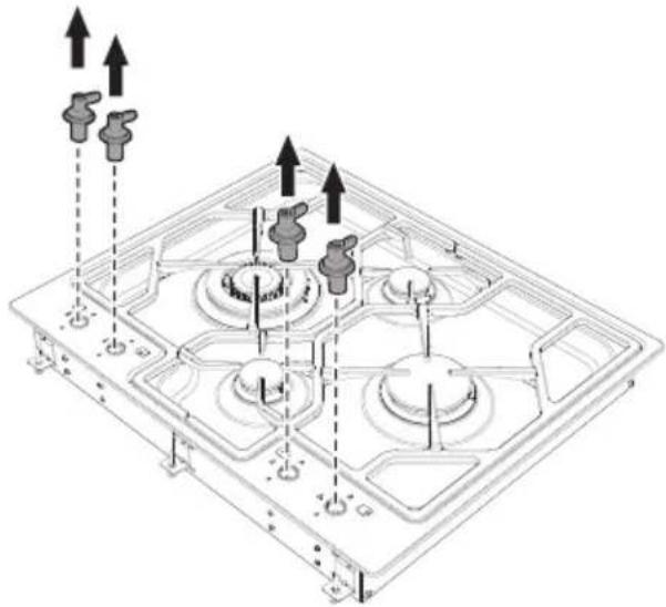
- Turn the regulating screw on the side of the cock stem until a steady minimum flame is achieved.
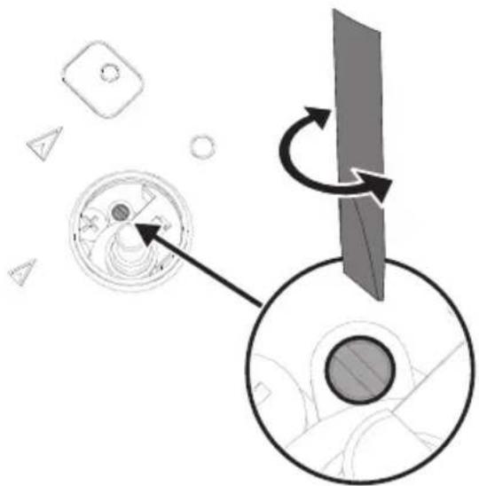
- Refit the knob and verify that the burner flame is stable.
- Turn the knob rapidly from the maximum to the minimum setting: The flame should not go out. Repeat the operation on all gas cocks.
Adjusting the minimum setting for LPG
Tighten the screw located at the side of the cock rod clockwise all the way.

Following adjustment to a gas other than the one originally set in the factory, replace the gas setting label on the appliance with the one corresponding to the new gas. The label is inserted inside the nozzle pack (where present).
Lubricating the gas taps
Over time the gas taps may become difficult to turn and get blocked. Clean them internally and replace the lubrication grease.
Lubrication of the gas cocks should be performed by a specialised technician.
Installation
Gas types and Countries
| Gas types | EN | GB-IE | FR-BE | DE | AT | ES | PT | SE | RU | DK | PL | HU |
| 1 Natural gas G20 | ||||||||||||
| G20 20 mbar | ● | ● | ● | ● | ● | ● | ● | ● | ● | |||
| G20/25 20/25 mbar | ● | |||||||||||
| 2 Natural gas G20 | ||||||||||||
| G20 25 mbar | ● | |||||||||||
| 3 Natural gas G25.1 | ||||||||||||
| G25.1 25 mbar | ● | |||||||||||
| 4 Natural gas G25 | ||||||||||||
| G25 20 mbar | ● | |||||||||||
| 5 Natural gas G27 | ||||||||||||
| G27 20 mbar | ● | |||||||||||
| 6 Natural gas G2.350 | ||||||||||||
| G2.350 13 mbar | ● | |||||||||||
| 7 LPG G30/31 | ||||||||||||
| G30/31 28/37 mbar | ● | ● | ● | ● | ||||||||
| G30/31 30/37 mbar | ● | ● | ||||||||||
| G30/31 30/30 mbar | ● | ● | ||||||||||
| 8 LPG G30/31 | ||||||||||||
| G30/31 37 mbar | ● | |||||||||||
| 9 LPG G30/31 | ||||||||||||
| G30/31 50 mbar | ● | ● | ||||||||||
| 10 Town gas G110 | ||||||||||||
| G110 8 mbar | ● | ● | ● | |||||||||
| 11 Town gas G120 | ||||||||||||
| G120 8 mbar | ● | |||||||||||

It is possible to identify the available gas types based on the country the appliance is to be installed in. Refer to the heading number to identify the correct values in the "Gas types and Countries".
Burner and nozzle characteristics tables
| 1 Natural gas G20 - 20 mbar AUX RR UR3 | ||||
| Rated heating capacity (kW) | 1.05 2.50 3.90 | |||
| Nozzle diameter (1/100 mm) | 72 108 135 | |||
| Reduced flow rate (W) | 400 800 1600 | |||
| Pre-chamber (printed on nozzle) | X | Y | K | |
| 2 Natural gas G20 - 25 mbar AUX RR UR3 | ||||
| Rated heating capacity (kW) | 1.05 2.50 3.90 | |||
| Nozzle diameter (1/100 mm) | 72 100 126 | |||
| Reduced flow rate (W) | 400 800 1600 | |||
| Pre-chamber (printed on nozzle) | X | F2 | K | |
| 3 Natural gas G25.1 - 25 mbar | AUX | RR | UR3 | |
| Rated heating capacity (kW) | 1.05 2.50 3.90 | |||
| Nozzle diameter (1/100 mm) | 77 115 148 | |||
| Reduced flow rate (W) | 400 800 1600 | |||
| Pre-chamber (printed on nozzle) | F1 F3 F3 | |||
| 4 Natural Gas G25 - 20 mbar | AUX | RR | UR3 | |
| Rated heating capacity (kW) | 1.05 2.50 3.90 | |||
| Nozzle diameter (1/100 mm) | 77 115 148 | |||
| Reduced flow rate (W) | 400 800 1600 | |||
| Pre-chumber (printed on nozzle) | F1 F3 F3 | |||
| 5 Natural Gas G27 - 20 mbar | AUX | RR | UR3 | |
| Rated heating capacity (kW) | 1.05 2.60 3.70 | |||
| Nozzle diameter (1/100 mm) | 77 134 152 | |||
| Reduced flow rate (W) | 400 800 1600 | |||
| Pre-chamber (printed on nozzle) | F1 Z F3 | |||
| 6 Natural gas G2.350 - 13 mbar | AUX | RR | UR3 | |
| Rated heating capacity (kW) | 1.00 2.50 3.80 | |||
| Nozzle diameter (1/100 mm) | 94 152 200 | |||
| Reduced flow rate (W) | 400 800 1600 | |||
| Pre-chamber (printed on nozzle) | Y | F | 3 | |
Installation
| 7 | LPG G30/31 - 30/37 mbar | AUX | RR | UR3 |
| Rated heating capacity (kW) | 1.05 2.50 3.90 | |||
| Nozzle diameter (1/100 mm) | 50 79 100 | |||
| Reduced flow rate (W) | 400 500 1600 | |||
| Pre-chamber (printed on nozzle) | - | H8 | - | |
| Rated flow rate G30 (g/h) | 76 182 284 | |||
| Rated flow rate G31 (g/h) | 75 179 279 | |||
| 8 | LPG G30/31 - 37 mbar | AUX | RR | UR3 |
| Rated heating capacity (kW) | 1.10 2.50 4.00 | |||
| Nozzle diameter (1/100 mm) | 50 75 94 | |||
| Reduced flow rate (W) | 400 800 1600 | |||
| Pre-chamber (printed on nozzle) | - | - | - | |
| Rated flow rate G30 (g/h) | 80 182 291 | |||
| Rated flow rate G31 (g/h) | 79 179 286 | |||
| 9 | LPG G30/31 - 50 mbar | AUX | RR | UR3 |
| Rated heating capacity (kW) | 1.05 2.50 3.90 | |||
| Nozzle diameter (1/100 mm) | 43 65 77 | |||
| Reduced flow rate (W) | 400 800 1600 | |||
| Pre-chamber (printed on nozzle) | H2 Z F4 | |||
| Rated flow rate G30 (g/h) | 76 182 284 | |||
| Rated flow rate G31 (g/h) | 75 179 279 | |||
| 10 | Town gas G110 – 8 mbar | AUX | RR | UR3 |
| Rated heating capacity (kW) | 1.05 2.50 3.80 | |||
| Nozzle diameter (1/100 mm) | 145 230 340 | |||
| Reduced flow rate (W) | 400 800 1200 | |||
| Pre-chamber (printed on nozzle) | /8 /3 /13 | |||
| 11 | Town gas G120 – 8 mbar | AUX | RR | UR3 |
| Rated heating capacity (kW) | 1.05 2.50 3.90 | |||
| Nozzle diameter (1/100 mm) | 135 220 315 | |||
| Reduced flow rate (W) | 400 800 1200 | |||
| Pre-chamber (printed on nozzle) | /8 /3 /13 |
The nozzles not provided are available at Authorised Service Centres.
5.6 Electrical connection

Power voltage Danger of electrocution
• Have the electrical connection performed by authorised technicians. • Use personal protective equipment. - The appliance must be connected to ground in compliance with electrical system safety standards. - Disconnect the mains power supply. - Do not pull the cable to remove the plug. - Use cables withstanding a temperature of at least 90°C. - The tightening torque of the screws of the terminal board leads must be 1.5 - 2 Nm.
General information
Check the mains characteristics against the data indicated on the plate.
The identification plate bearing the technical data, serial number and brand name is visibly positioned on the appliance.
Do not remove this plate for any reason.
Perform the ground connection using a wire that is 20 mm longer than the other wires.

Pass the power supply cable through the back of the unit, taking care that it does not touch the bottom casing of the hob or the oven (if any) installed underneath it.
The appliance can work in the following modes:
- 220-240 V 1N~

Use a 3 × 0.75 mm² three-core cable.

The values indicated above refer to the cross-section of the internal lead.
Fixed connection
Fit the power line with an all-pole disconnection switch, with at least 3 mm or more between its contacts, in compliance with installation regulations.
The circuit breaker should be located near the appliance and in an easily reachable position.
Connection with plug and socket
Make sure that the plug and socket are of the same type.
Avoid using adapters and shunts as these could cause overheating and a risk of burns.
Testing
At the end of installation, carry out a brief inspection test. If the hob fails to operate, after checking that you have carried out the instructions correctly, unplug the appliance and contact Technical Support.
5.7 Instructions for the installer
- The plug must be accessible after installation. Do not bend or trap the power cable.
- The appliance must be installed according to the installation diagrams.
- Do not try to unscrew or force the threaded elbow of the fitting. You may damage this part of the appliance, which may void the manufacturer's warranty.
- Use soap and water to check for gas leaks on all connections. DO NOT use naked flames to find leaks.
- Turn on all the burners separately and then all together to make sure that the gas valve, burner and ignition are working properly.
- Turn the burner knobs to the minimum position and check that the flame is stable for each individual burner and all the burners together.
- If the appliance does not work correctly after having carried out all the checks, contact your local Authorised Service Centre.
- Once the appliance has been installed, please explain to the user how to use it correctly.


- DESCRIPTION
- USE
- CLEANING AND MAINTENANCE
- INSTALLATION
- INSTRUCTIONS
- GENERAL SAFETY INSTRUCTIONS
- RISK OF PERSONAL INJURY
- RISK OF DAMAGING THE APPLIANCE
- FOR THIS APPLIANCE
- MANUFACTURER LIABILITY
- APPLIANCE PURPOSE
- IDENTIFICATION PLATE
- THIS USER MANUAL
- DISPOSAL
- POWER VOLTAGE DANGER OF ELECTROCUTION
- PLASTIC PACKAGING DANGER OF SUFFOCATION
- HOW TO READ THE USER MANUAL
- GENERAL DESCRIPTION
- SYMBOLS
- BURNER KNOBS
- AVAILABLE ACCESSORIES
- RAISED PAN STAND
- IMPROPER USE DANGER OF BURNS
- IMPROPER USE RISK OF DAMAGE TO SURFACES
- FIRST USE
- USING THE HOB
- POSITIONING THE PAN STANDS
- CORRECT POSITIONING OF THE FLAME-SPREADER CROWNS AND BURNER CAPS
- PRACTICAL TIPS FOR USING THE HOB
- LIMITATIONS ON GRIDDLE USE
- CLEANING THE APPLIANCE
- ORDINARY DAILY CLEANING
- FOOD STAINS OR RESIDUES
- COOKING HOB GRIDS
- FLAME-SPREADER CROWNS AND BURNER CAPS
- KNOBS
- IGNITERS AND THERMOCOUPLES
- SAFETY INSTRUCTIONS
- POSITIONING IN THE COUNTER TOP
- FIXING TO THE TRADITIONAL BUILT-IN MODEL SUPPORT STRUCTURE
- FIXING TO THE FLUSH BUILT-IN MODEL SUPPORT STRUCTURE
- MOUNTING
- OVER BUILT-IN OVEN UNIT
- OVER EMPTY KITCHEN UNIT OR DRAWERS
- GAS CONNECTION
- GAS LEAK DANGER OF EXPLOSION
- GENERAL INFORMATION
- CONNECTION WITH A STEEL HOSE
- CONNECTION WITH A STEEL HOSE WITH CONICAL FITTING
- CONNECTION TO LPG
- ROOM VENTILATION
- EXTRACTION OF THE COMBUSTION PRODUCTS
- ADAPTATION TO DIFFERENT TYPES OF GAS
- CHANGING THE NOZZLES
- ADJUSTING THE MINIMUM SETTING FOR NATURAL OR TOWN GAS
- ADJUSTING THE MINIMUM SETTING FOR LPG
- LUBRICATING THE GAS TAPS
- ELECTRICAL CONNECTION
- FIXED CONNECTION
- CONNECTION WITH PLUG AND SOCKET
- TESTING
- INSTRUCTIONS FOR THE INSTALLER
Brand : SMEG
Model : PGF64SA
Category : Cooker