
DPMX-1216 MP - Dimmer Eurolite - Free user manual and instructions
Find the device manual for free DPMX-1216 MP Eurolite in PDF.


| Product Type | DMX Dimmer Pack |
| Model | DPMX-1216 MP |
| Channels | 16 |
| Rated Voltage | 230 V AC, 50/60 Hz |
| Max Load per Channel | 10 A (2300 W) |
| Total Max Load | 40 A (9200 W) |
| Control Protocol | DMX512 |
| DMX Connector | 5-pin XLR input/output |
| Dimming Curve | Selectable linear or square law |
| Protections | Overload, short circuit, overheat |
| Cooling | Internal fan |
| Dimensions (W x D x H) | 483 x 300 x 88 mm (19", 2U) |
| Weight | 6.5 kg |
| Operating Temperature | 0°C to 40°C |
| Housing Material | Steel, powder coated |
| Display | LED status indicators per channel |
| Mounting | 19" rack mount |
| Maintenance | Clean with soft dry cloth; avoid solvents |
| Safety Notes | Keep away from moisture; ensure proper ventilation |
| Spare Parts / Repairability | Replacement fuses and internal modules available from service centers |
Frequently Asked Questions - DPMX-1216 MP Eurolite
User questions about DPMX-1216 MP Eurolite
0 question about this device. Answer the ones you know or ask your own.
Ask a new question about this device
Download the instructions for your Dimmer in PDF format for free! Find your manual DPMX-1216 MP - Eurolite and take your electronic device back in hand. On this page are published all the documents necessary for the use of your device. DPMX-1216 MP by Eurolite.
USER MANUAL DPMX-1216 MP Eurolite
natural_image
Front view of a black industrial power supply unit with multiple ports and control panel (no visible text or symbols)Inhaltsverzeichnis/
Table of contents
Deutsch
4.2 Front panel of the EUROLITE DPMX-1216 20
4.3 Dimmer module of the EUROLITE DPMX-1216 20
4.4 Control module of the EUROLITE DPMX-1216 21
4.5 Rear panel of the EUROLITE DPMX-1216 21
4.5.1 EUROLITE DPMX-1216 CEE 22
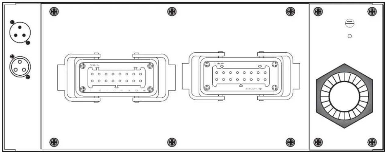
4.5.2 EUROLITE DPMX-1216 MP 22
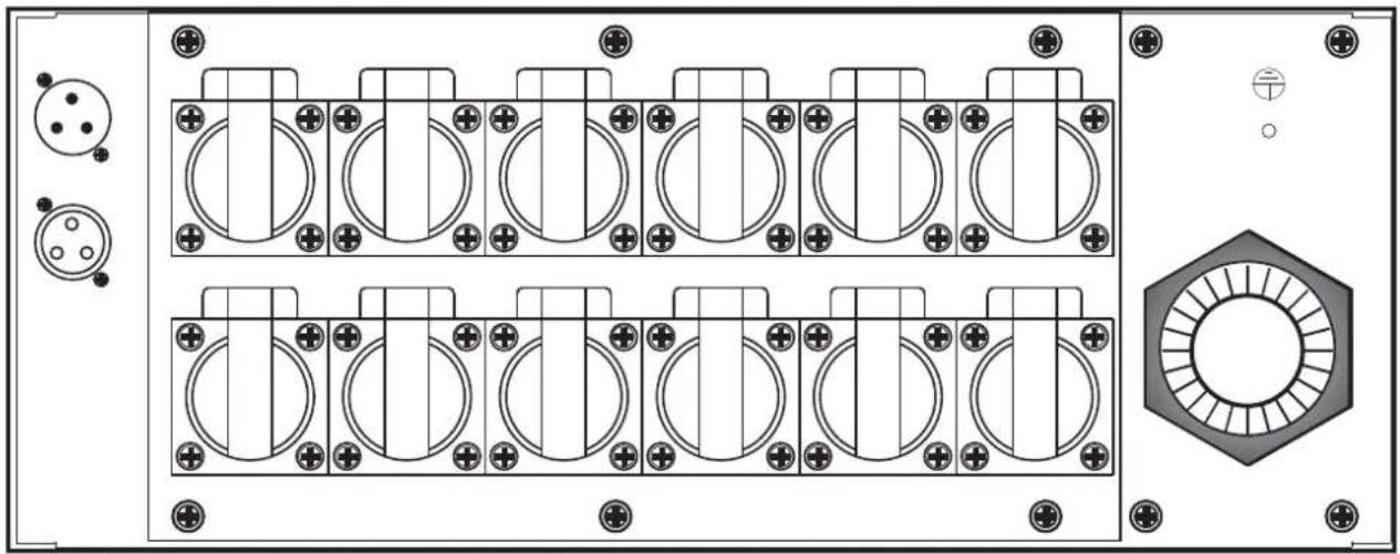
4.5.3 EUROLITE DPMX-1216 S 22
-
INSTALLATION 23
-
CONNECTIONS 23
6.1 Connection example 23
6.2 Connecting the lamps 23
6.3 Connection with the mains....24
6.4 Connection to the DMX-512 controller / connection between fixtures.... 24
Addressing 25
- OPERATION 25
7.1 Setting into operation....25
7.2 How to navigate through the menu 25
7.2.1 DMX FAIL (REACTION WHEN DMX SIGNAL FAILS TO COME) 25
7.2.2 DMX ADDR (ADDRESSING, DMX OPERATING MODES) 25
7.2.3 PREHEAT 26
7.2.4 MAX LEVEL (CHANNEL LIMITATION) 26
7.2.5 CURVE (TRANSMISSION CHARACTERISTIC) 26
7.2.6 MANUAL (MANUAL LIGHT CONTROL) 27
-
CLEANING AND MAINTENANCE 27
-
TECHNICAL SPECIFICATIONS....28
Top view of the EUROLITE DPMX-1216 DMX 29
This user manual is valid for the article numbers: 70064180, 70064182, 70064183, 70064185
natural_image
Technical diagram of a device rear panel with circular components and a hexagonal component (no text or symbols)natural_image
Technical diagram of a dual-chamber electronic component with mounting holes and internal square slots (no text or symbols)4.5.2 EUROLITE DPMX-1216 MP
natural_image
Technical diagram of two electronic device connectors with pinouts and mounting points (no text or symbols)4.5.3 EUROLITE DPMX-1216 S
natural_image
Technical diagram of a mechanical or electrical component with multiple circular and rectangular features, no visible text or symbols.5. INSTALLATION
Keep this device away from rain and moisture! Unplug mains lead before opening the housing!
For your own safety, please read this user manual carefully before you initially start-up.
Every person involved with the installation, operation and maintenance of this device has to
- be qualified
- follow the instructions of this manual
- consider this manual to be part of the total product
- keep this manual for the entire service life of the product
- pass this manual on to every further owner or user of the product
- download the latest version of the user manual from the Internet
1. INTRODUCTION
Thank you for having chosen an EUROLITE Dimmer pack of the DPMX-1216 DMX series. If you follow the instructions given in this manual, we are sure that you will enjoy this device for a long period of time.
Unpack your Eurolite Dimmer pack.
2. SAFETY INSTRUCTIONS

CAUTION!
Be careful with your operations. With a dangerous voltage you can suffer a dangerous electric shock when touching the wires!
This device has left our premises in absolutely perfect condition. In order to maintain this condition and to ensure a safe operation, it is absolutely necessary for the user to follow the safety instructions and warning notes written in this user manual.

Important:
Damages caused by the disregard of this user manual are not subject to warranty. The dealer will not accept liability for any resulting defects or problems.
If the device has been exposed to drastic temperature fluctuation (e.g. after transportation), do not switch it on immediately. The arising condensation water might damage your device. Leave the device switched off until it has reached room temperature.
English
Please make sure that there are no obvious transport damages. Should you notice any damages on the A/C connection cable or on the casing, do not take the device into operation and immediately consult your local dealer.
This device falls under protection-class I. The power plug must only be plugged into a protection class I outlet. The voltage and frequency must exactly be the same as stated on the device. Wrong voltages or power outlets can lead to the destruction of the device and to mortal electrical shock.
Always plug in the power plug least. The power plug must always be inserted without force. Make sure that the plug is tightly connected with the outlet.
Never let the power-cord come into contact with other cables! Handle the power-cord and all connections with the mains with particular caution! Never touch them with wet hands, as this could lead to mortal electrical shock.
Never modify, bend, strain mechanically, put pressure on, pull or heat up the power cord. Never operate next to sources of heat or cold. Disregard can lead to power cord damages, fire or mortal electrical shock.
The cable insert or the female part in the device must never be strained. There must always be sufficient cable to the device. Otherwise, the cable may be damaged which may lead to mortal damage.
Make sure that the power-cord is never crimped or damaged by sharp edges. Check the device and the power-cord from time to time.
If extension cords are used, make sure that the core diameter is sufficient for the required power consumption of the device. All warnings concerning the power cords are also valid for possible extension cords.
Always disconnect from the mains, when the device is not in use or before cleaning it. Only handle the power-cord by the plug. Never pull out the plug by tugging the power-cord. Otherwise, the cable or plug can be damaged leading to mortal electrical shock. If the power plug or the power switch is not accessible, the device must be disconnected via the mains.
If the power plug or the device is dusty, the device must be taken out of operation, disconnected and then be cleaned with a dry cloth. Dust can reduce the insulation which may lead to mortal electrical shock. More severe dirt in and at the device should only be removed by a specialist.
There must never enter any liquid into power outlets, extension cords or any holes in the housing of the device. If you suppose that also a minimal amount of liquid may have entered the device, it must immediately be disconnected. This is also valid, if the device was exposed to high humidity. Also if the device is still running, the device must be checked by a specialist if the liquid has reduced any insulation. Reduced insulation can cause mortal electrical shock.
There must never be any objects entering into the device. This is especially valid for metal parts. If any metal parts like staples or coarse metal chips enter into the device, the device must be taken out of operation and disconnected immediately. Malfunction or short-circuits caused by metal parts may cause mortal injuries.
Keep away children and amateurs!
Never leave this device running unattended.
3. OPERATING DETERMINATIONS
This device is an electronic dimmer for dimming other devices like spots in discotheques, on stages etc. This product is allowed to be operated with an alternating current of 230 V - 380 V, 50 Hz and was designed for indoor use only.
Do not shake the device. Avoid brute force when installing or operating the device.
When choosing the installation-spot, please make sure that the device is not exposed to extreme heat, moisture or dust. There should not be any cables lying around. You endanger your own and the safety of others!
English
This device must never be operated or stockpiled in sourroundings where splash water, rain, moisture or fog may harm the device. Moisture or very high humidity can reduce the insulation and lead to mortal electrical shocks. When using smoke machines, make sure that the device is never exposed to the direct smoke jet and is installed in a distance of 0.5 meters between smoke machine and device. The room must only be saturated with an amount of smoke that the visibility will always be more than 10 meters.
The ambient temperature must always be between -5^ C and +45^ C. Keep away from direct insulation (particularly in cars) and heaters.
The relative humidity must not exceed 50 % with an ambient temperature of 45^ C.
This device must only be operated in an altitude between -20 and 2000 m over NN.
Never use the device during thunderstorms. Over voltage could destroy the device. Always disconnect the device during thunderstorms.
Operate the device only after having familiarized with its functions. Do not permit operation by persons not qualified for operating the device. Most damages are the result of unprofessional operation!
Please use the original packaging if the device is to be transported.
Please consider that unauthorized modifications on the device are forbidden due to safety reasons!
Never remove the serial barcode from the device as this would make the guarantee void.
If this device will be operated in any way different to the one described in this manual, the product may suffer damages and the guarantee becomes void. Furthermore, any other operation may lead to dangers like short-circuit, burns, electric shock, etc.
4. DESCRIPTION OF THE DEVICE
4.1 Features
Professional digital 12-channel modular power-pack
• 12-channel DMX-controlled dimmer pack with up to 16 A output per channel
- Modular design of the individual dimmer modules and the control module for quick and easy change
• 3-phase or 1-phase power supply
- Adjustable lamp preheat (0-50%) and limiter function to prolong bulb life
- Curve function for selection of different fade modes
- Dim or Switch option assignable to each channel
- DMX Fail function: automatic digital input check to detect DMX signal errors
- Manual mode for dimming capability without an external lighting controller
- All modes are displayed via LCD
- Synchronization of several devices possible via DMX
- With automatic circuit breaker per channel (type C)
- Channel-outputs on the rear panel depending on the model via pole connectors; Safety, CEE or 16-pin sockets
- 19" dimensions with 4 U
English
The following chapters describe the control elements on the front panel of the EUROLITE DPMX-1216 DMX as a reference.
4.2 Front panel of the EUROLITE DPMX-1216
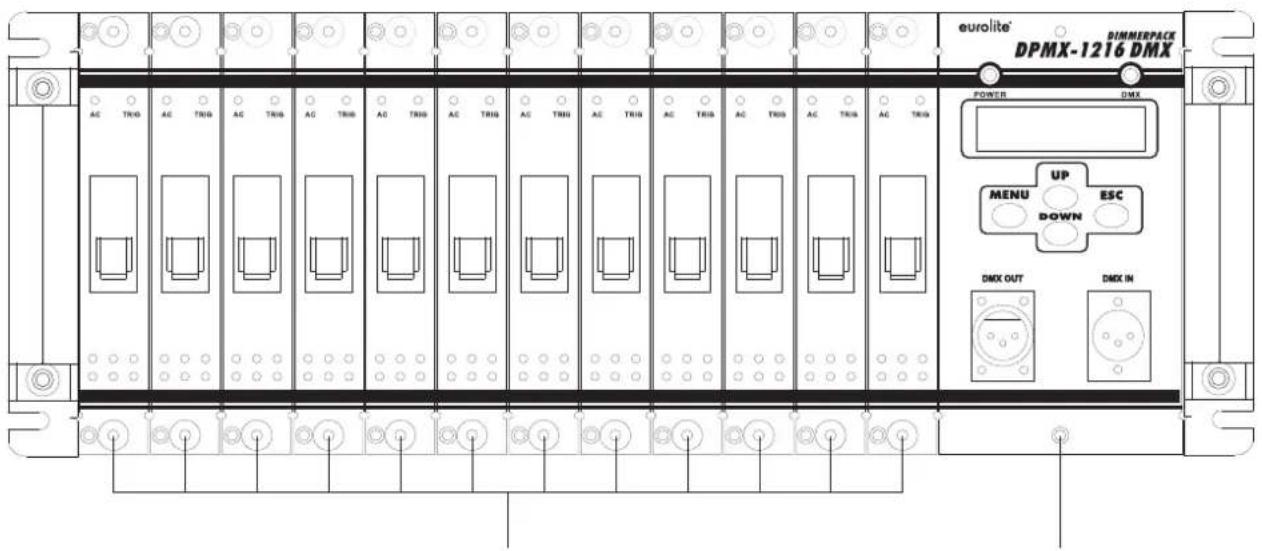
12 x Dimmer module Control module
4.3 Dimmer module of the EUROLITE DPMX-1216

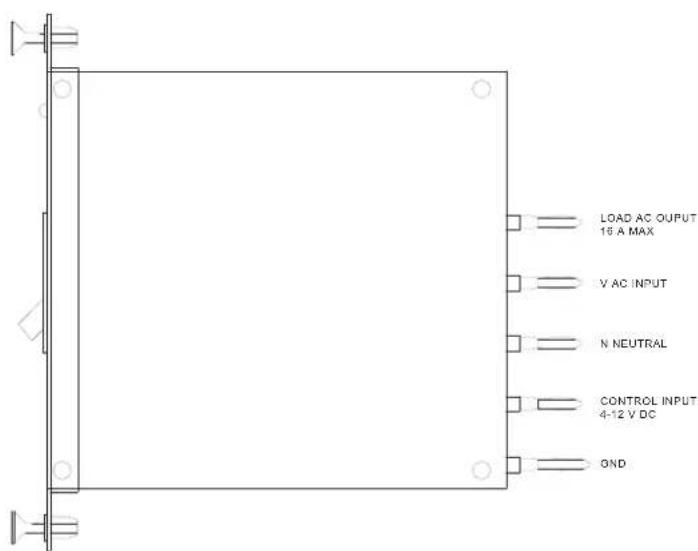
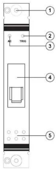
1. Module mounting holder
Pull holder to change the module. Press to replace. The dimmer pack must be disconnected from the mains first.
2. AC Indicator
3. TRIG Indicator
4. Circuit breaker
Engages in the event of overload or short circuit.
5. Ventilation openings
English
4.4 Control module of the EUROLITE DPMX-1216

6. DMX Indicator
Lights up when the device is receiving a DMX signal.
7. POWER Indicator
Lights up as soon as the device is supplied with power.
8. LCD
Displays all menus and values.
9. UP Button
For editing in the menus.
10. MENU Button
For advancing to the next menu level
11. DOWN Button
For editing in the menus.
12. ESC Button
Exit sub-menus by pressing ESC.
13. DMX OUT Socket
3-pin XLR output for connecting an additional dimmer pack.
14. DMX IN Socket
3-pin XLR input for connecting DMX 512 control signals. Connect your DMX controller here.
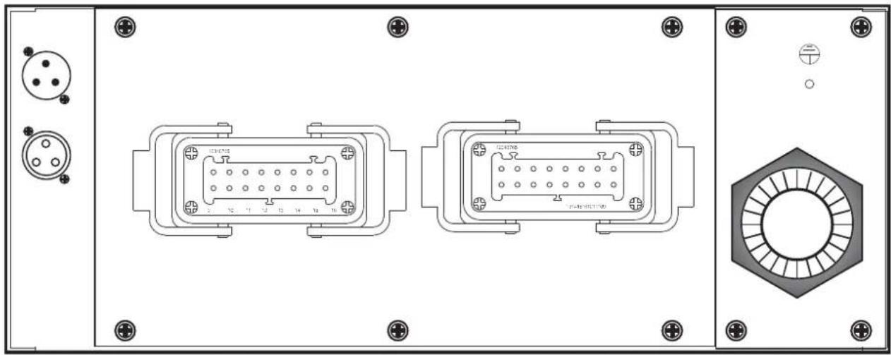
4.5 Rear panel of the EUROLITE DPMX-1216

natural_image
Technical diagram of an electronic device front panel with circular components and a hexagonal component (no text or symbols)15. DMX Connectors
You can route the DMX control signal to additional Dimmer packs by using the 3-pin DMX OUT XLR connector. The 3-pin XLR input is for connecting DMX 512 control signals. Connect your DMX controller here.
16. Outputs
Cable slot for connectiong the lamps.
17. Power Supply
Cable slot for the power supply.
4.5.1 EUROLITE DPMX-1216 CEE

natural_image
Technical diagram of a dual-chamber electronic component with mounting holes and internal square slots, plus a hexagonal nut assembly (no text or symbols)4.5.2 EUROLITE DPMX-1216 MP
natural_image
Technical diagram of two identical electrical connector modules with pinouts and mounting points (no text or symbols)4.5.3 EUROLITE DPMX-1216 S

natural_image
Technical diagram of a mechanical or electrical component with multiple circular and rectangular features, no visible text or symbols.5. INSTALLATION
Install the device on a plane surface or install it in a rack.
5.1 Rack installation
This device is built for 19" racks (483 mm). The rack you use should be a Double-Door-Rack where you can open the front panel and the rear panel. The rack should be provided with a cooling fan. When mounting the device into the rack, please make sure that there is enough space around the device so that the heated air can be passed on. Steady overheating will damage your device.
You can fix the device with four screws M6 in the rack.
6. CONNECTIONS
6.1 Connection example

flowchart
graph TD
    A["EUROLITE DPMX-1216 DMX rear"] --> B["12x EUROLITE PAR-64 Profi Spot"]
    A --> C["EUROLITE DPMX-1216 S DMX rear"]
    B --> D["120 Ω"]
    C --> E["11x EUROLITE PAR-64 Profi Spot"]
    D --> F["DMX OUT"]
    D --> G["DMX IN"]
    E --> H["DMX OUT"]
    E --> I["DMX IN"]
    F --> J["EUROLITE DPMX-1216 DMX rear"]
    G --> K["EUROLITE DPMX-1216 S DMX rear"]
    H --> L["EUROLITE DPMX Stage Control front"]
Connection example of the EUROLITE DPMX-1216 DMX and EUROLITE DPMX-1216 S DMX with the Controller EUROLITE DMX Stage Control, the theatre spots EUROLITE PAR-64 (dim mode) and the fog machine EUROLITE NX-150 (switch mode).
6.2 Connecting the lamps

CAUTION!
Unplug mains lead before connecting lamps!
Connect your loads via the connectors. The maximum load per channel is 3680 W. Please note that the maximum current of 189 A must never be exceeded!
The DPMX-1216 DMX uses terminal blocks as output connectors beneath the blind plate on the rear panel. The DPMX-1216 DMX MP uses 16-pin industrial sockets as output connectors located on the rear panel. The DPMX-1216 DMX S uses safety sockets as output connectors located on the rear panel. The DPMX-1216 DMX CEE uses CEE sockets as output connectors located on the rear panel.
6.3 Connection with the mains
DANGER TO LIFE!
The electric connection must only be carried out by a qualified electrician!
The occupation of the connection-cables is as follows:
| Cable | Pin | International |
| Black | Live1 | L1 |
| Brown | Live2 | L2 |
| Grey | Live3 | L3 |
| Blue | Neutral | N |
| Yellow/Green | Earth |  |
The earth has to be connected!
If the device will be directly connected with the local power supply network, a disconnection switch with a minimum opening of 3 mm at every pole has to be included in the permanent electrical installation.
The device must only be connected with an electric installation carried out in compliance with the IEC-standards. The electric installation must be equipped with a Residual Current Device (RCD) with a maximum fault current of 30 mA.
6.4 Connection to the DMX-512 controller / connection between fixtures

The wires must not come into contact with each other, otherwise the devices will not work at all, or will not work properly.


Please note, the starting address depends upon which controller is being used.

Only use a stereo shielded cable and 3-pin XLR-plugs and connectors in order to connect the controller with the device or one device with another.
Occupation of the XLR-connection:
DMX-output
XLR mounting-socket:

1: Ground
2: Signal (−)
3: Signal (+)
DMX-input
XLR mounting-plug:

1: Ground
2: Signal (−)
3: Signal (+)
If you are using controllers with this occupation, you can connect the DMX-output of the controller directly with the DMX-input of the first device in the DMX-chain. If you wish to connect DMX-controllers with other XLR-outputs, you need to use adapter-cables.
Building a serial DMX-chain:
Connect the DMX-output of the first device in the DMX-chain with the DMX-input of the next device. Always connect one output with the input of the next device until all devices are connected.
English
Caution: At the last device, the DMX-cable has to be terminated with a terminator. Solder a 120 Ω resistor between Signal (−) and Signal (+) into a 3-pin XLR-plug and plug it in the DMX-output of the last device.
Addressing
Set the required DMX-address according the description under chapter 7.2.2 „DMX addr“.
7. OPERATION
7.1 Setting into operation
After connecting the EUROLITE DPMX-1216 DMX Dimmer pack to the mains, the unit starts running. The POWR indicator lights up. „EUROLITE“ and “WELCOME TO USE” is indicated on the display. During this indication, the unit is conducting a self-test and recalls the previous memory record afterwards; „Running Progxx“ or „DMX MODE“. If the unit receives a DMX signal, the DMX indicator lights up. You are now in the main menu.
7.2 How to navigate through the menu
In the following subchapters every menu is discribed in detail. Please use the buttons below the LCD to navigate through the menu and for data input. The underscore on the display indicates your position in the menu.
By pressing the buttons UP/DOWN you can select the individual menus [DMX Fail, DMX addr, Preheat, Max level, Curve and Manual]. Enter one of the menus by pressing the button MENU. You are now in the corresponding submenu. By using the buttons UP/DOWN you can set the parameters. The values can be increased or decreased by 1. Keep the button UP or DOWN pressed for two seconds to change the values faster. Exit the individual menu by pressing ESC. If no button in the submenus is pressed within 20 seconds the unit exits automatically to the main menu.
| Button Function | |
| MENU | Enter the menu, confirm |
| UP | Navigation up, data input |
| DOWN | Navigation down, data input |
| ESC | Exit the menu |
7.2.1 DMX Fail (reaction when DMX signal fails to come)
Here you can determine the unit's reaction when the DMX control signal transmission is interrupted.
| Display Function Button | ||
| Dmx failProg08SpeedValue=00.4S | Selects a built-in program [1-12], that is to run when the DMX signal transmission is interrupted. DMX signals are always prior to built-in programs.The speed of the programs can be set in the submenu [00.1-20.0S]. | MENUUP/DOWNMENUUP/DOWNESC |
7.2.2 DMX addr (Addressing, DMX operating modes)
Depending on the operation mode Block or Single, you can set one or several DMX addresses for an individual channel or several channels.
| Display Function Button | ||
| Dmx addrBlockStart addrValue=[044] | BLOCK | The entire dimmer operates on one DMX start address. Set an address for the first channel in the submenu [001-512]. Every next channel gets a DMX address which is one number higher. | MENUUP/DOWNESC |
| Dmx addrSingleDmx addr CH[01]Value=[023] | SINGLE | Set a start address in the submenu for each of the 12 channels individually [001-512]. Two or more channels can share the same address. Use the button MENU to navigate from „Dmx addr CH [XX]“ to „Value=[XX]“. | MENUUP/DOWNESCMENUUP/DOWNESC |
7.2.3 Preheat
Here you can determine the preheat value, which is then continuously run to the devices connected in series (e.g. theater spots). This function results in lower start-up current requirement and prolongs the life of the illuminants. The preheat value can be assigned to all 12 channels in mode All or to each channel individually in mode Single. The Preheat function cannot be used in switch mode.
| Display Function Button | ||
| Preheat AllValue=[20%] | ALL | Set the preheat value for all 12 channels [0-50%]. MENU | UP/DOWNESC |
| Preheat CH[01]Value=[023%] | SINGLE | Set the preheat value for each of the 12 channel individually [0-50%]. Use the button MENU to navigate from „Preheat CH [XX]“ to „Value=[XX]“. | MENUUP/DOWNMENUUP/DOWNESC |
7.2.4 Max level (channel limitation)
Here you can set an upper limit for the control signal of each individual channel. The limiter function, too, prolongs the life of your illuminants. Limiting the upper range of control voltage protects form voltage oscillations and overdrive. Depending on the mode, you can set a value for all channels or for each channel individually. The Max level function cannot be used in switch mode.
| Display Function Button | ||
| Max levelAll | ALL | Limits all channels to a maximum level [0-100%]. MENU | UP/DOWNESC |
| Max level CH[01]Value=[023%] | SINGLE | Each channel can be preheated individually [0-100%]. Use the button MENU to navigate from „Max level CH [XX]“ to „Value=[XX]“. | MENUUP/DOWNMENUUP/DOWNESC |
7.2.5 Curve (transmission characteristic)
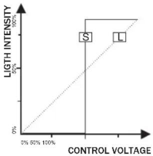
line
| CONTROL VOLTAGE | LIGTH INTENSITY | | --------------- | --------------- | | 0% | 0% | | 50% | 50% | | 100% | 100% |Here you can set up the transmission characteristic of your Dimmer pack. You can determine how control voltage (fader movement on the controller) is transmitted to the units connected in series. Depending on the mode, you can adjust a curve for all channels or for each channel individually.
[L] | The default mode is „linear“. Here the ratio of input value and output level is linear, i.e. when the fader on the controller is moved up or down, the light intensity of the lamp connected in series changes directly proportionate to the fader movement.
[S] | When set to switch mode, the respective channel works like an electronic relay. This way, you can control fog machines, motors and other effects units
[When the control voltage reaches 50% or more of a previously set value, the channel is switched on; when it falls below 50%, the channel is switched off again]. The Preheat and Max level functions cannot be used in switch mode.
| Display Function Button | ||
| CurveAll | ALL | Define one curve for all channels [Linear or Switch]. MENU | UP/DOWNESC |
| Curve AllValue=[Linear] | ||
| Curve CH[01] | SINGLE | Adjust transmission curves for each individual channel. [Linear or | MENU |
| Value=[Linear] | Switch]. Use the button MENU to navigate from „Curve CH [XX]“ to „Value = [X]“. | UP/DOWN |
| Curve CH[01] | MENU | |
| Value=[Switch] | UP/DOWN | |
| ESC | ||
7.2.6 Manual (manual light control)
In manual mode, the Dimmer pack can be used without an external controller and the channels can be adjusted manually via the buttons below the LCD. Depending on the mode, you can adjust a value for all channels or for each channel individually. The manual control cannot be used in DMX mode. The values set in the menu „Manual“ do not affect the built-in programs (DMX Fail function), however, they must be within the upper limit, set in the menu „Max level“ (channel limitation). Contrary to the DMX mode (DMX Fail functions), the manual mode has no power failure function.
| Display Function Button | ||
| ManualAllManual AllValue = [20%] | ALL | Assign a value to all 12 channels [0-100%]. MENU | UP/DOWNMENUUP/DOWNESC |
| Manual CH[01]Value=[023%] | SINGLE | Assign a value to each of the 12 channels individually [0-100%]. Use the button MENU to navigate from „Manual CH [XX]“ to „Value = [XX]“. | MENUUP/DOWNMENUUP/DOWNMENUUP/DOWNESC |
8. CLEANING AND MAINTENANCE

DANGER TO LIFE!
Disconnect from mains before starting maintenance operation!
We recommend a frequent cleaning of the device. Please use a soft lint-free and moistened cloth. Never use alcohol or solvents!
There are no serviceable parts inside the device. Maintenance and service operations are only to be carried out by authorized dealers.
If the fuse interrupts, please reset the breaker.
Should you need any spare parts, please use genuine parts.
If the power supply cable of this device will be damaged, it has to be replaced by authorized dealers only in order to avoid hazards.
If defective, please dispose of the unusable device in accordance with the current legal regulations.
Should you have further questions, please contact your dealer.
9. TECHNICAL SPECIFICATIONS
| Power supply: | 230-380 V AC, 50 Hz ~ |
| Max. power output: | 43470W |
| Max. current: 189 A | |
| Max. output/channel: | 3680 W |
| Max. current/channel: | 16 A |
| Number of control-channels: | 12 |
| Integrated programs: | 12 |
| Fuse: | 12 x C 16 A, 230 V |
| DMX output: | 3-pin female XLR socket |
| DMX input: | 3-pin male XLR socket |
| Outputs: | |
| DPMX-1216 Pole connectors | |
| DPMX-1216 S Safety sockets | |
| DPMX-1216 CEE CEE sockets | |
| DPMX-1216 MP 16-pin sockets | |
| Dimensions (WxDxH): 482 x 485 x 176 mm | |
| Minimum mounting depth: | 500 mm |
| Weight: | 27 kg |
| Accessory: | |
| DPMX Dimmer-Modul 1216 MK1 No. | 70064192 |
Please note: Every information is subject to change without prior notice. 07.08.2014 ©
| DPMX-1216No. 70064180 EAN 4026397265422230-380 V AC, 50 Hz ~Max. power output: 43470 WMax. total current: 189 AMax. output/channel: 3680 WMax. current/channel: 16 A |
| eurolite®CESteinigke Showtechnic GmbH Andreas-Bauer-Str. 597297 Waldbutterbrunn Germany www.steinigke.de |
!WARNING!
- When single phase input, L1, L2, L3 must be short circuited via wires.
- When three phase input, neutral wire must be securely connected.
- This apparatus must be earthed.
- Designed for indoor use intention.
- No customer serviceable parts inside.
DPMX-1216 DMX DIMMERPACK
| BASIC MENUS | SUB-MENUS | ESC: Exit | |||
| MENU↓UP/DOWN | DMX Fail | MENU↓UP/DOWN | DMX: Only to receive DMX signal | Press MENU or ESC to exit. | |
| Prog. 1-12; Starts Internal programs 1-12 | Press ESC to enter speed setting, then press UP/DOWN to set speed value [0.1-20 seconds].Press ESC to exit. | ||||
| DMX addr | Block: Set starting address | Press MENU to enter Block mode, press UP/DOWN to set address [001-512]. | |||
| Single: Set DMX address for Individual channel | Press MENU to select channel or address mode. In channel mode, press UP/DOWN to select a channel [CH1-CH2]. In address mode, press UP/DOWN to set address [001-512]. | ||||
| Preheat | All: Set Preheat value for all channels | Press MENU to enter All mode, press UP/DOWN to set Preheat value [000-50%]. | |||
| Single: Set Preheat value for Individual channel | Press MENU to select channel or value mode. In channel mode, press UP/DOWN to select a channel [CH1-CH2]. In value mode, press UP/DOWN to set a value [000-100%]. | ||||
| Max level | All: Set Max level for all channels | Press MENU to enter All mode, press UP/DOWN to set Max level value [000-100%]. | |||
| Single: Set Max level for Individual channel | Press MENU to select channel or value mode. In channel mode, press UP/DOWN to select a channel [CH1-CH2]. In value mode, press UP/DOWN to set a value [000-100%]. | ||||
| Curve | All: Set dimming for all channels | Press MENU to enter All mode, press UP/DOWN to select linear or switch. | |||
| Single: Set dimming for Individual channel | Press MENU to select channel or dimming mode. In channel mode, press UP/DOWN to select a channel [CH1-CH2]. In dimming mode, press UP/DOWN to select linear or switch. | ||||
| Manual | All: Set manual value for all channels | Press MENU to enter All mode, press UP/DOWN to set manual value [000-100%]. | |||
| Single: Set manual for Individual channel | Press MENU to select channel or value mode. In channel mode, press UP/DOWN to select a channel [CH1-CH2]. In value mode, press UP/DOWN to set a value [000-100%]. | ||||



- Inhaltsverzeichnis/
- Table of contents
- Deutsch
- EUROLITE DPMX-1216 MP
- EUROLITE DPMX-1216 S
- INSTALLATION
- INTRODUCTION
- SAFETY INSTRUCTIONS
- CAUTION!
- Important:
- English
- OPERATING DETERMINATIONS
- DESCRIPTION OF THE DEVICE
- Features
- Professional digital 12-channel modular power-pack
- Front panel of the EUROLITE DPMX-1216
- Dimmer module of the EUROLITE DPMX-1216
- Module mounting holder
- AC Indicator
- TRIG Indicator
- Circuit breaker
- Ventilation openings
- Control module of the EUROLITE DPMX-1216
- DMX Indicator
- POWER Indicator
- LCD
- UP Button
- MENU Button
- DOWN Button
- ESC Button
- DMX OUT Socket
- DMX IN Socket
- Rear panel of the EUROLITE DPMX-1216
- DMX Connectors
- Outputs
- Power Supply
- EUROLITE DPMX-1216 CEE
- Rack installation
- CONNECTIONS
- Connection example
- Connecting the lamps
- Connection with the mains
- DANGER TO LIFE!
- Connection to the DMX-512 controller / connection between fixtures
- DMX-output
- DMX-input
- Building a serial DMX-chain:
- Addressing
- OPERATION
- Setting into operation
- How to navigate through the menu
- DMX Fail (reaction when DMX signal fails to come)
- DMX addr (Addressing, DMX operating modes)
- Preheat
- Max level (channel limitation)
- Curve (transmission characteristic)
- Manual (manual light control)
- CLEANING AND MAINTENANCE
- TECHNICAL SPECIFICATIONS
- !WARNING!
Brand : Eurolite
Model : DPMX-1216 MP
Category : Dimmer