
591270 - Heating Rheem - Free user manual and instructions
Find the device manual for free 591270 Rheem in PDF.


| Product Type | Gas Water Heater |
| Model | 591270 |
| Brand | Rheem |
| Capacity | 50 Gallons |
| Dimensions (H x W x D) | 60 x 20 x 20 inches |
| Weight | 150 lbs |
| Power Source | Natural Gas or Propane |
| BTU Input | 40,000 BTU/h |
| Energy Efficiency | 0.67 Uniform Energy Factor (UEF) |
| Venting Type | Power Vent / Direct Vent |
| Temperature Setting Range | 90°F - 150°F (32°C - 66°C) |
| Recovery Rate | 40 gallons per hour (at 90°F rise) |
| Anode Rod | Corrosion-resistant magnesium or aluminum |
| Pressure Relief Valve | Included (150 psi) |
| Thermostat Type | Adjustable Gas Valve |
| Ignition | Electronic Ignition (Direct Spark) |
| Maintenance | Annual flushing and anode rod inspection |
| Safety Features | Flame Rollout Sensor, Thermocouple, T&P Valve |
| Warranty | 6 Years on Tank, 1 Year on Parts |
| Certifications | ANSI Z21.10.1, CSA 4.1 |
| Installation Required | Professional installation recommended |
| Spare Parts Availability | Available through Rheem authorized distributors |
| Manual Format | PDF (68 pages, English) |
Frequently Asked Questions - 591270 Rheem
User questions about 591270 Rheem
0 question about this device. Answer the ones you know or ask your own.
Ask a new question about this device
Download the instructions for your Heating in PDF format for free! Find your manual 591270 - Rheem and take your electronic device back in hand. On this page are published all the documents necessary for the use of your device. 591270 by Rheem.
USER MANUAL 591270 Rheem
Installation Instructions
natural_image
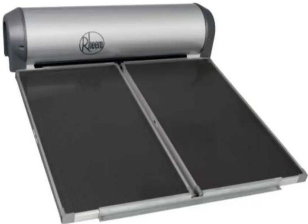
Rheem solar water heater with open lid and two rectangular compartments (no text or symbols visible)Solar Thermosiphon Water Heater
Stainless Steel Tanks

Install a Rheem

WARNING: Plumber – Be Aware
Use copper pipe ONLY. Plastic pipe MUST NOT be used.
It is a requirement of a solar water heater installation that all pipe work be in copper and not plastic, due to the effects of high water temperatures.

WARNING: Plumber – Be Aware
- The solar hot and solar cold pipe work between the thermosiphon solar storage tank and the solar collectors are supplied in the pipe kit. The supplied copper solar hot and solar cold pipes MUST BE used.
- If the solar water heater is installed either on a metal roof or in a trafficable area, such as on an accessible roof, then the solar hot and solar cold pipes must be insulated. The solar hot and solar cold pipes may be required to be insulated to comply with local regulations.
If insulation is required, the full length of the solar hot and solar cold pipes MUST BE insulated.
The insulation must:
- be of a closed cell type or equivalent, suitable for a solar water heating application and capable of withstanding the temperature of the water or closed circuit fluid generated by the solar collectors under stagnation conditions
The specification of the chosen insulation material should be checked with the insulation manufacturer prior to installation as different materials may vary in temperature tolerance. - be at least 13 mm thick, however thicker insulation may be required to comply with the requirements of AS/NZS 3500.4
■ be weatherproof and UV resistant
■ be fitted up to and cover the connections on both the solar storage tank and the solar collectors.
The insulation will offer corrosion protection to a metal roof against water runoff over the copper pipe, assist in avoiding accidental contact with the solar pipe work as high temperature water or closed circuit fluid can flow from the solar collectors to the solar storage tank and also reduce pipe heat losses.
- Plastic pipe MUST NOT be used, as it will not withstand the temperature and pressure of the closed circuit fluid (indirect system) and water (direct system) generated by the solar collectors under stagnation conditions. The solar collectors can generate extremely high water or closed circuit fluid temperatures up to 150°C and high water pressure of 850 kPa. Plastic pipe cannot withstand these temperatures and pressures and MUST NOT be used. Failure of plastic pipe can lead to the release of high temperature closed circuit fluid and water and cause severe water damage and flooding.
- There must be a continuous fall of a minimum 10^ in the pipe work from the thermosiphon solar storage tank to the solar collectors. The highest point of the solar cold pipe and solar hot pipe must be where they connect to the thermosiphon solar storage tank, otherwise thermosiphoning will not occur.
- The solar water heater is to be isolated during the testing and commissioning of the heated water reticulation system in a building, in accordance with Clause 11.1 and 11.3 (a) of AS/NZS 3500.4.
PATENTS
This water heater may be protected by one or more patents or registered designs in the name of Rheem Australia Pty Ltd.
TRADE MARKS
® Registered trademark of Rheem Australia Pty Ltd.
^TM Trademark of Rheem Australia Pty Ltd.
Note: Every care has been taken to ensure accuracy in preparation of this publication. No liability can be accepted for any consequences, which may arise as a result of its application.
CONTENTS
HOUSEHOLDER – We recommend you read pages 4 to 18.
The other pages are intended for the installer but may be of interest.
About Your Water Heater....4
Regular Care 11
Water Supplies.... 13
Save A Service Call 16
Installation.... 19
Installation – Solar Collectors.... 34
System Assembly 37
Connections – Plumbing 51
Connections – Electrical.... 54
Multiple Installations....57
Commissioning....59
Draining The Solar Storage Tank....62
Draining The Closed Circuit - 52H / RLX Series 63
Flushing the Water Heater....64
Warranty 66
WATER HEATER APPLICATION
This water heater is designed for use in a single family domestic dwelling for the purpose of heating potable water. Its use in an application other than this may shorten its life.
MODEL TYPE
Your Rheem ^® thermosiphon solar water heater is designed for both the solar collectors and the solar storage tank to be roof mounted. The solar storage tank has a Colorbond jacket. The 52L tank (direct system) is suitable for installation with Rheem Australis or Titan solar collectors (RL series) and the 52H tank (indirect system) is suitable for installation with Rheem S200 (52H series), Australis or Titan solar collectors (RLX series).
The 52L and RL series systems do not have freeze protection. These systems are not suitable for installation in areas subject to frost or freeze conditions. Freeze conditions occur below 6°C. These systems have NO WARRANTY for freeze damage (refer to “Terms of the Rheem Warranty” on page 66).
The 52H and RLX series systems are suitable for installation in areas subject to frost or freeze conditions. Freeze conditions occur below 6°C. These systems have NO WARRANTY for freeze damage if non Rheem approved closed circuit fluid has been used or if the closed circuit fluid has been incorrectly mixed (refer to "Terms of the Rheem Warranty" on page 66).
This water heater is designed to be installed as an electric boosted solar water heater with its booster heating unit connected to a power supply, however it may be installed with an in-series continuous flow or storage booster.
If this water heater is installed with an in-series booster, then the electric booster heating unit will not be connected to a power supply and the references to the electric booster heating unit, thermostat and boosting controls in this Guide will not be applicable to the installation. For information relating to the function and operation of the in-series booster, refer to the Owners Guide and Installation Instructions supplied with the booster water heater.
SOLAR OPERATION
The Rheem solar thermosiphon system has its stainless steel solar storage tank installed on the roof directly coupled to the solar collectors. The 52L and RL series are direct solar hot water systems and the 52H and RLX series are indirect solar hot water systems with a heat exchanger in the solar storage tank.
52L, RL series: The solar storage tank and solar collectors are connected by copper pipe work and form an open circuit which is filled with potable water.
52H, RLX series: The heat exchanger and solar collectors are connected by copper pipe work and form a closed circuit which is filled with closed circuit fluid. The closed circuit fluid is a solution of a blue, non-toxic food grade propylene glycol concentrate mixed with water. The closed circuit concentrate is used to lower the freezing temperature of the closed circuit fluid and provides protection against freezing. The closed circuit also provides protection to the solar collectors and solar pipe work against harsh water chemistry.
The solar water heater works on the simple scientific fact that hot fluid rises. As the sun heats the water or closed circuit fluid in the solar collectors, the increase in temperature causes the fluid to rise through a copper pipe into the storage tank (52L, RL series) or heat exchanger (52H, RLX series) where it transfers its heat into the water in the solar storage tank. This allows cooler fluid from the storage tank or heat exchanger to flow into the solar collectors to be heated by the sun's energy. This process continues while solar energy is available.

natural_image
Simple line drawing of a house with a roof, windows, and bushes at the base (no text or symbols)Automatic safety controls are fitted to the water heater to provide safe and efficient operation.
ELECTRIC BOOSTING
Water stored in the solar storage tank can be heated by an electric booster heating unit. The booster heating unit is for heating the water at times of low solar energy gain, such as during very cloudy or rainy weather, or during the colder months.
The amount of water heated by the raised booster heating unit of the thermosiphon solar storage tank is 90 litres (180 tank) or 150 litres (300 tank).
The thermosiphon solar water heater is most suited for the booster heating unit to be connected to either a continuous, or a time of use, or an extended Off-Peak (overnight and day) electricity supply. A timer can also be used to control the boosting periods and help maximise solar savings. Refer to “Booster Control” on page 7.
The booster heating unit may be connected to an Off-Peak (overnight) electricity supply, however this will only allow the booster to heat the water overnight. If this type of connection is considered, care must be taken to ensure there is sufficient boost capacity to meet the household's full day and night's hot water supply during periods of no or low solar gain, particularly in cold weather. There is also an increased risk of temperature run down occurring, particularly in cooler weather (refer to "Temperature Run Down" on page 7).
The booster heating unit is controlled by an electric thermostat. The thermostat and its over temperature energy cut out are mounted on the solar storage tank behind the front cover. The water temperature is automatically controlled to the thermostat setting when the booster heating unit is energised.
MAINS PRESSURE
The water heater is designed to operate at mains pressure by connecting directly to the mains water supply. If the mains supply pressure in your area exceeds that shown on page 21, a pressure limiting valve must be fitted. The supply pressure should be greater than 350 kPa for true mains pressure operation to be achieved.
The temperature the system will operate at under solar radiation will depend upon the level of solar radiation available, orientation and inclination of the solar collectors, incoming cold water temperature and volume of hot water used.
Under normal household use and average operating conditions, the system may achieve a water temperature of approximately twice the maximum daily outside air temperature. During periods high solar radiation conditions and low hot water consumption, a system fitted with an over temperature protection (OTP) system may heat the water up to 85^ C, whilst the water temperature could exceed 85^ C for a system without OTP.
During periods of low solar energy gain, the water temperature can be boosted by the thermostatically controlled electric booster heating unit. Refer to “Booster Control” on page 7.

Rheem recommends the thermostat is set at 60^ C to maximise solar contribution.
Note: AS 3498 requires that a water heater provides the means to inhibit the growth of Legionella bacteria in potable water. This water heater can satisfy this AS 3498 requirement provided the electric booster is energised for a sufficient period each day and the electric booster thermostat setting is 60°C or higher.
If this water heater is installed with an in-series continuous flow gas booster, then this requirement of AS 3498 can be satisfied provided the booster is energised, its preset outlet temperature setting is 70^ C or higher and a remote temperature controller is not used.
If this water heater is installed with an in-series storage booster, then this requirement of AS 3498 can be satisfied provided the storage booster is energised and its thermostat setting is 60^ C or higher.
HOTTER WATER INCREASES THE RISK OF SCALD INJURY
This water heater can deliver water at temperatures which can cause scalding. Check the water temperature before use, such as when entering a shower or filling a bath or basin, to ensure it is suitable for the application and will not cause scald injury.
We recommend and it may also be required by regulations that an approved temperature limiting device be fitted into the hot water pipe work to the bathroom and ensuite when this water heater is installed. This will keep the water temperature below 50^ C at the bathroom and ensuite. The risk of scald injury will be reduced and still allow hotter water to the kitchen and laundry.
TEMPERATURE ADJUSTMENT
The water heater features a tradesperson adjustable thermostat. This requires a licensed tradesperson to make any temperature adjustments. The thermostat has a maximum temperature setting of 70^ C and a minimum temperature setting of 60^ C.
We advise you have your electrician adjust the thermostat to the lowest setting which meets your needs, especially if there are young children or elderly people in the home. Refer to “Hotter Water Increases the Risk of Scald Injury” on page 6.
WARNING
This water heater is only intended to be operated by persons who have the experience or the knowledge and the capabilities to do so. This water heater is not intended to be operated by persons with reduced physical, sensory or mental capabilities i.e. the infirm, or by children. Children should be supervised to ensure they do not interfere with the water heater.
This water heater uses 240 V AC power for the electrically operated components. The removal of the side cover will expose 240 V wiring. It must only be removed by a qualified person.
Care should be taken not to touch any exposed pipe work or fittings connecting the solar storage tank and the solar collectors, as this may result in a burn injury. Very high temperature closed circuit fluid or hot water and in some circumstances high temperature steam can be generated by the solar collectors under certain conditions and flow through the pipe work from the solar collectors to the solar storage tank.
Note: Any exposed pipe work or fittings in the solar circuit should be attended to and covered with insulation. Phone Rheem Service or their nearest Accredited Service Agent to arrange for an inspection.
Should the water from a 52H or RLX series water heater appear blue or if blue closed circuit fluid is noticed around the base of the water heater or solar collectors, this indicates a leak of the closed circuit fluid from the heat exchanger or the solar collectors. The closed circuit fluid is non-toxic and not hazardous to health. Phone Rheem Service or their nearest Accredited Service Agent to arrange for an inspection.
SAFETY
This water heater is supplied with a thermostat, an over-temperature cut-out, and a combination temperature pressure relief valve. These devices must not be tampered with or removed. The water heater must not be operated unless each of these devices is fitted and is in working order.
The operation of the over-temperature cut-out on the thermostat indicates a possibly dangerous situation. If the over-temperature cut-out operates, it must not be reset and the water heater must be serviced by a qualified person.
If the electrical conduit to the solar storage tank is damaged, it must be replaced by a qualified person in order to avoid a hazard. Phone Rheem Service or their nearest Accredited Service Agent to arrange for an inspection.
⚠ Warning: For continued safety of this water heater it must be installed, operated and maintained in accordance with the Owner's Guide and Installation Instructions.
The Rheem warranty may not cover faults if relief valves or other safety devices are tampered with or if the installation is not in accordance with these instructions.
PRECAUTIONS
Where damage to property can occur in the event of the water heater leaking, the water heater must be installed in a safe tray. Construction, installation and draining of a safe tray must comply with AS/NZS 3500.4 and all local codes and regulatory authority requirements.
The water heater must be maintained in accordance with the Owner's Guide and Installation Instructions. Refer to "Regular Care" on page 11.
If this water heater is to be used where an uninterrupted hot water supply is necessary for your application or business you should ensure that you have back up redundancy within the hot water system design. This should ensure the continuity of hot water supply in the event that this water heater were to become inoperable for any reason. We recommend you seek advice from your plumber or specifier about your needs and building back up redundancy into your hot water supply system.
Temperature run down is the reduction in water temperature as the hotter water at the top of the storage cylinder transfers some of its heat to the cooler water in the lower section of the cylinder.
This effect is often perceived as heat loss, but is actually the redistribution of stored heat more evenly over the entire contents of the storage tank. This heat is not lost to the system. This may make it necessary to use the booster to raise the water in the top section of the cylinder back to an acceptable temperature.
Over-night temperature run down is most evident in the morning if the booster switch or time clock is left OFF over-night. It is more prevalent the more hot water is used the night before and also in the cooler months. Day time temperature run down is quite evident on days of lower solar radiation particularly during the cooler months if the power to the booster heating element is not available, or the booster switch or time clock is left OFF.
If higher temperature water is required, particularly in the morning, then use of the booster heating unit is necessary to raise the temperature of the water in the top section of the cylinder. Refer to “Booster Control” on page 7.
BOOSTER CONTROL
An isolating switch is installed in the electrical meter box for the solar storage tank. This should be left switched on to allow the booster heating unit to operate if required. The booster heating unit is for heating the water at times of low solar energy gain, such as during very cloudy or rainy weather, or during the colder months.
The booster heating unit will only activate if heating is required and power is available from the switchboard. When the water is below the thermostat setting, the booster heating unit will turn on and heat the water. The booster heating unit will automatically turn off when the temperature of the water reaches the thermostat setting.
Leaving the isolating switch switched on will also provide a sufficient period of time each day for the booster heating unit to operate, if required, to satisfy the requirements of AS 3498.
The amount of water heated by the raised booster heating unit of the thermosiphon solar storage tank will be 90 litres (180 tank) or 150 litres (300 tank).
Timer Control Switch
A suitably rated timer control switch can be installed and will help maximise energy savings with an electrically boosted solar water heater connected to a continuous, time of use or extended Off-Peak (overnight and day) electricity supply.
If used with an extended Off-Peak (overnight and day) electricity supply, the timer switch should:
- be operated by a continuous power supply on its own circuit from the switchboard with the booster heating unit operated by the Off-Peak power supply. A double pole isolating switch is required to be installed at the switchboard to simultaneously isolate both circuits.
or
- be of a type which has an internal rechargeable battery to keep time when the power supply is not available to the timer.
Programming the Timer
Power must be available to the timer control switch before the booster heating unit can be activated.
The timer should be programmed:
• to suit the hot water consumption pattern of the household,
- with the end of the period to coincide with the commencement of the evening hot water usage,
(a second period, such as prior to the morning hot water usage, may be necessary)
- to enable a boosting period of not less than the recommended continuous length of time for boosting, and
- for a period when power will be available for the booster heating unit to operate.
Note: When daylight saving time applies, you may consider resetting the timer accordingly.
The recommended continuous length of time for boosting is:
| Booster heating unit size | ||||||
| Model | Minimum winter cold water temperature | Temperature rise | 2.4 kW | 3.6 kW | 4.8 kW | |
| 180 | Cool / temperate climate | 10°C | 50°C | 2 1/4 hours | 1 1/2 hours | 1 1/4 hours |
| Temperate / sub tropical climate | 15°C | 45°C | 2 hours | 1 1/2 hours | 1 hour | |
| Tropical climate | 20°C | 40°C | 1 3/4 hours | 1 1/4 hours | 1 hour | |
| 300 | Cool / temperate climate | 10°C | 50°C | 3 3⁄4 hours | 2 1⁄2 hours | 2 hours |
| Temperate / sub tropical climate | 15°C | 45°C | 3 1⁄2 hours | 2 1⁄4 hours | 1 3⁄4 hours | |
| Tropical climate | 20°C | 40°C | 3 hours | 2 hours | 1 1⁄2 hours |
The recommended boosting periods are sufficient to allow the booster heating unit to heat up the boost volume of the solar storage tank to 60^ C where the winter cold water temperatures do not fall below those shown. This may be necessary during periods of very low solar energy gain through the solar collectors, such as during constant rain or extremely cloudy weather, particularly in winter when the incoming cold water temperature is lower. The period will also provide a sufficient heat up time for the electric booster to operate, if required, to satisfy the requirements of AS 3498.
The booster heating unit will only activate if heating is required and power is available from the timer. When the water is below the thermostat setting, the booster heating unit will turn on and heat the water. The booster heating unit will automatically turn off either when the temperature of the water reaches the thermostat setting or at the end of the timer period, whichever comes first.
RAIN WATER TANK
If the 52H or RLX series solar water heater is installed on a section of roof which is part of a rain water runoff collection system, then it is recommended this section of roof and its gutter be isolated from the rain water collection system. The gutter should be isolated to a width greater than the solar water heater and pipe work and must have suitable drainage. This is to ensure in the event of a leak from the closed circuit, a rainwater tank cannot be contaminated with closed circuit fluid.
The closed circuit fluid contains food grade additives (rust inhibitor and anti-freeze agent), is non-toxic and is harmless to the environment. However, if it enters a rain water tank it can cause an unpleasant odour to develop and result in the rain water tank having to be drained and cleaned.
FREEZE PROTECTION
The 52H and RLX series solar water heaters are an indirect closed circuit solar hot water system with a heat exchanger in the solar storage tank. The heat exchanger and solar collectors form a closed circuit and are filled with closed circuit fluid. The closed circuit fluid is a solution of a blue, non-toxic food grade propylene glycol concentrate mixed with water. The closed circuit concentrate is used to lower the freezing temperature of the closed circuit fluid and provides protection against freezing.
During installation, the closed circuit concentrate is blended with water. The amount of closed circuit concentrate supplied with this water heater provides protection in frost prone areas to a temperature of -8^ . If lower temperatures are anticipated, a greater concentration of closed circuit fluid will be required.
The system has NO WARRANTY for freeze damage if non Rheem approved closed circuit fluid has been used or if the closed circuit fluid has been incorrectly mixed (refer to “Terms of the Rheem Warranty” on page 66).
The 52L and RL series systems do not have freeze protection. The system is not suitable for installation in areas subject to frost or freeze conditions. Freeze conditions occur below 6°C. The system has NO WARRANTY for freeze damage (refer to “Terms of the Rheem Warranty” on page 66).
PIPE WORK AND INSULATION
The solar hot and solar cold pipe work between the thermosiphon solar storage tank and the solar collectors are supplied in the pipe kit. The supplied copper solar hot and solar cold pipes MUST BE used.
If the solar water heater is installed either on a metal roof or in a trafficable area, such as on an accessible roof, then the solar hot and solar cold pipes must be insulated. The solar hot and solar cold pipes may be required to be insulated to comply with local regulations.
If insulation is required, the full length of the solar hot and solar cold pipes MUST BE insulated.
Note: Any exposed pipe work or fittings in the solar circuit should be attended to and covered with insulation. Phone Rheem Service or their nearest Accredited Service Agent to arrange for an inspection.
The insulation must:
- be of a closed cell type or equivalent, suitable for a solar water heating application and capable of withstanding the temperature of the water or closed circuit fluid generated by the solar collectors under stagnation conditions
The specification of the chosen insulation material should be checked with the insulation manufacturer prior to installation as different materials may vary in temperature tolerance. - be at least 13 mm thick, however thicker insulation may be required to comply with the requirements of AS/NZS 3500.4
- be weatherproof and UV resistant
- be fitted up to and cover the connections on both the solar storage tank and the solar collectors.
The insulation will offer corrosion protection to a metal roof against water runoff over the copper pipe, assist in avoiding accidental contact with the solar pipe work as high temperature water or closed circuit fluid can flow from the solar collectors to the solar storage tank and also reduce pipe heat losses.
Plastic pipe MUST NOT be used, as it will not withstand the temperature and pressure of the closed circuit fluid generated by the solar collectors under certain conditions (refer to Warning on page 36).
The pipe work between the solar storage tank and in-series booster (if one is installed) MUST BE of copper and fully insulated with a closed cell type insulation or equivalent (minimum thickness 13 mm).
TO TURN OFF THE WATER HEATER
If you plan to be away from home for a few nights, we suggest you leave the water heater switched on.
If it is necessary to turn off the water heater:
- Switch off the electrical supply at the isolating switch to the solar storage tank.
- Close the cold water isolation valve at the inlet to the water heater.
TO TURN ON THE WATER HEATER
- Open the cold water isolation valve fully at the inlet to the water heater.
- Switch on the electrical supply at the isolating switch to the solar storage tank.
- Check and if required reset the timer, if one is installed.
GOING ON HOLIDAYS
If you plan to be away from home, conserve energy by switching the booster switch "OFF". Refer to "To Turn Off The Water Heater" on page 10. Also if the system is not used for a period in excess of 2 weeks it is recommended the solar collectors be covered.
Care should be taken when returning from holidays and the collectors have not been covered. The water in the storage tank can be very hot.
HOW DO I KNOW IF THE WATER HEATER IS INSTALLED CORRECTLY?
The water heater must be installed:
• by a qualified person, and
- in accordance with the installation instructions, and
- in compliance with Standards AS/NZS 3500.4, AS/NZS 3000 and all local codes and regulatory authority requirements.
In New Zealand, the installation must also conform with Clause G12 of the New Zealand Building Code.
VICTORIAN CUSTOMERS
Notice to Victorian Customers from the Victorian Plumbing Industry Commission. This water heater must be installed by a licensed person as required by the Victorian Building Act 1993.
Only a licensed person will give you a Compliance Certificate, showing that the work complies with all the relevant Standards. Only a licensed person will have insurance protecting their workmanship for 6 years. Make sure you use a licensed person to install this water heater and ask for your Compliance Certificate.
DOES THE WATER CHEMISTRY AFFECT THE WATER HEATER?
The water heater is suitable for most public water supplies, however some water chemistries may have detrimental effects on the water heater, its components and fittings. Refer to “Water Supplies” on page 13.
If you are in a known harsh water area or you are not sure of your water chemistry, have your water checked against the conditions described on pages 13 to 15.
HOW LONG WILL THE WATER HEATER LAST?
The water heater is supported by a manufacturer's warranty (refer to page 66). There are a number of factors that will affect the length of service the water heater will provide. These include but are not limited to the water chemistry, the water pressure, the water temperature (inlet and outlet) and the water usage pattern. Refer to “Precautions” on page 7.
MINOR SIX MONTH MAINTENANCE
It is recommended minor maintenance be performed every six months by the dwelling occupant.
The minor maintenance includes:
- Operate the easing lever on the temperature pressure relief valve (if accessible). It is very important you raise and lower the lever gently. Refer to “Temperature Pressure Relief Valve” on page 12.
If the relief valve lever is not readily and safely accessible, contact Rheem Service or their nearest Accredited Service Agent. Do not attempt to climb onto a non-trafficable roof to operate the relief valve lever.
⚠ Warning: Exercise care to avoid any splashing of water, as water discharged from the drain line will be hot. Stand clear of the drain line's point of discharge when operating the valve's lever.
- Operate the easing lever on the expansion control valve (if fitted). It is very important you raise and lower the lever gently. Refer to “Expansion Control Valve” on page 12.
- Check the drain line from the safe tray (if one is installed) is not blocked.
MAJOR FIVE YEAR SERVICE
It is recommended a major five year service be conducted on the water heater.
⚠ Warning: Servicing of a water heater must only be carried out by a qualified person. Phone Rheem Service or their nearest Accredited Service Agent.
Note: The five year service and routine replacement of any components, such as the relief valves, are not included in the Rheem warranty. A charge will be made for this work. Only genuine replacement parts should be used on this water heater.
The major service includes the following actions:
- Replace the temperature pressure relief valve.
- Inspect and flush the expansion control valve (if fitted). If required, replace the valve.
- Check the booster heating unit for excessive calcium build up or corrosion and replace if necessary.
- Check the closed circuit fluid level (52H / RLX series).
- Flush and bleed the solar collectors (52L / RL series).
- Clean the collector glass.
- Visually check the unit for any potential problems.
- Inspect all connections.
- Check the drain line from the safe tray (if one is installed) is not blocked.
Note: The solar storage tank may need to be drained during this service. After the completion of the service, the solar storage tank will take some time to reheat the water by solar gain. Depending upon the power supply connection to the booster heating unit, hot water may not be available until the next day.
TEMPERATURE PRESSURE RELIEF VALVE
This valve is near the top of the water heater and is essential for its safe operation. It is possible for the valve to release a little water through the drain line during each heating period. This occurs as the water is heated and expands by approximately 1/50 of its volume.
Continuous leakage of water from the valve and its drain line may indicate a problem with the water heater (refer to "Temperature Pressure Relief Valve Running" on page 17).
⚠ Warning: Never block the outlet of this valve or its drain line for any reason.
Operate the easing lever on the temperature pressure relief valve once every six months. It is very important you raise and lower the lever gently.
⚠️ DANGER: Failure to do this may result in the water heater cylinder failing, or under certain circumstances, exploding.
⚠ Warning: Exercise care to avoid any splashing of water, as water discharged from the drain line will be hot. Stand clear of the drain line's point of discharge when operating the valve's lever.

If water does not flow freely from the drain line when the lever is lifted, then the water heater must be checked. Phone Rheem Service or their nearest Accredited Service Agent to arrange for an inspection.
If the relief valve lever is not readily and safely accessible, contact Rheem Service or their nearest Accredited Service Agent. Do not attempt to climb onto a non-trafficable roof to operate the relief valve lever.
The temperature pressure relief valve should be replaced at intervals not exceeding 5 years, or more frequently in areas where there is a high incidence of water deposits (refer to "Water Supplies" on page 13).
EXPANSION CONTROL VALVE
In many areas, including Queensland, South Australia, Western Australia and scaling water areas, an expansion control valve is fitted to the cold water line to the water heater. The expansion control valve may discharge a small quantity of water from its drain line during the heating period instead of the temperature pressure relief valve on the water heater.
Operate the easing lever on the expansion control valve once every six months. It is very important you raise and lower the lever gently. The expansion control valve should be checked for performance or replaced at intervals not exceeding 5 years, or more frequently in areas where there is a high incidence of water deposits.
COLLECTOR GLASS
Ensure the glass on your solar collectors is free of dust, salt spray or any other matter, which may reduce the effectiveness of the solar collectors. If the collector glass becomes dirty, hose down or if the solar collectors are accessible, wash the collector glass with water and a soft brush when the solar collectors are cool.
Have any trees trimmed which may shade the solar collectors.
Rheem solar collectors have passed the AS/NZS 2712 requirements for resistance to hailstone damage, so it is not normally necessary to fit a guard to a collector. Stone Guards are available to provide a level of protection to the collectors against vandalism or accidental damage. Refer to your local Solar Distributor for details.
This water heater must be installed in accordance with this advice to be covered by the Rheem warranty.
This water heater is manufactured to suit the water conditions of most public reticulated water supplies. However, there are some known water chemistries which can have detrimental effects on the water heater and its operation and/or life expectancy. If you are unsure of your water chemistry, you may be able to obtain information from your local water supply authority. This water heater should only be connected to a water supply which complies with these guidelines for the Rheem warranty to apply.
CHANGE OF WATER SUPPLY
The changing or alternating from one water supply to another can have a detrimental effect on the operation and / or life expectation of a water heater cylinder, a heat exchanger in an indirect solar water heater system, a temperature pressure relief valve, a heating unit and a solar collector in a direct solar water heater system.
Where there is a changeover from one water supply to another, e.g. a rainwater tank supply, bore water supply, desalinated water supply, public reticulated water supply or water brought in from another supply, then water chemistry information should be sought from the supplier or it should be tested to ensure the water supply meets the requirements given in these guidelines for the Rheem warranty to apply.
CHLORIDE AND PH
In a high chloride water supply, the water can corrode stainless steel parts and cause them to fail.
Where the chloride level exceeds 250 mg/L the Rheem warranty does not apply to a stainless steel cylinder or a heat exchanger in a 52H cylinder.
pH is a measure of whether the water is alkaline or acid. In an acidic water supply, the water can attack stainless steel parts and cause them to fail.
Where the pH is less than 6.0 the Rheem warranty does not apply to a stainless steel cylinder or a heat exchanger in a 52H cylinder. Water with a pH less than 6.0 may be treated to raise the pH.
The water supply from a rainwater tank in a metropolitan area is likely to be corrosive due to the dissolution of atmospheric contaminants. This may result in pH of less than 6.0. It is recommended an analysis on the water from a rainwater tank be conducted prior to connecting this type of water supply to a water heater with a stainless steel cylinder.
Refer to the pH and Chloride chart on page 13.

line
| pH | CHLORIDE - mg/L | |-------|-----------------| | 4.0 | 75 | | 5.0 | 75 | | 6.0 | 75 | | 7.0 | 75 | | 8.0 | 75 | | 9.0 | 75 |SATURATION INDEX
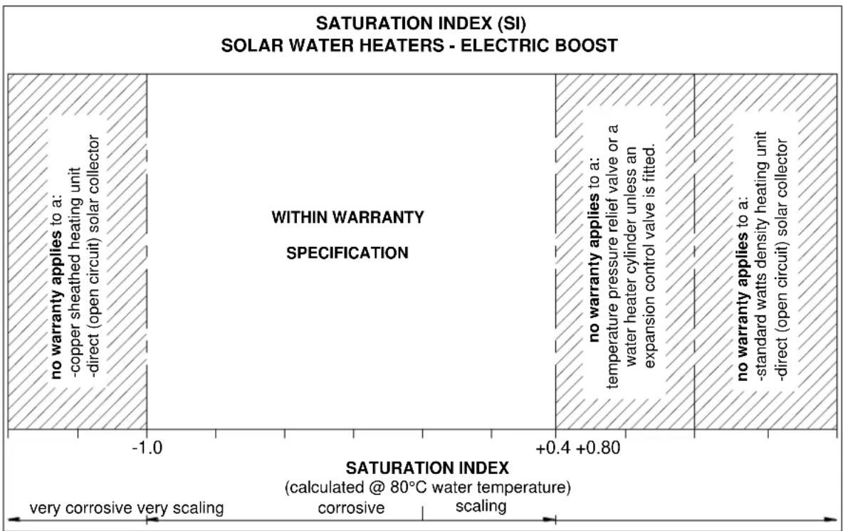
The saturation index is used as a measure of the water's corrosive or scaling properties.
In a corrosive water supply, the water can attack copper parts and cause them to fail. Where the saturation index is less than -1.0, the water is very corrosive and the Rheem warranty does not apply to a copper sheathed heating unit or a solar collector in a direct solar water heater system. A corrosion resistant heating and an indirect solar water heater must be used unit must be used for the Rheem warranty to apply to the heating unit and solar collector. This water heater is supplied fitted with a corrosion resistant heating unit.
In a scaling water supply calcium carbonate is deposited out of the water onto any hot metallic surface.
Where the saturation index exceeds +0.40, the water is very scaling. An expansion control valve must be fitted on the cold water line after the non-return valve to protect and for the Rheem warranty to apply to the temperature pressure relief valve and water heater cylinder. Solar collectors in a direct solar water heater system should be covered when the water heater is not intended to be used for more than two weeks.
Where the saturation index exceeds +0.80, the Rheem warranty does not apply to a standard watts density heating unit or a solar collector in a direct solar water heater system. A low watts density heating unit or an indirect solar water heater must be used for the Rheem warranty to apply to the heating unit or solar collector.
Water which is scaling may be treated with a water softening device to reduce the saturation index of the water.
Refer to the Saturation Index chart on page 14. Refer to the cold water connection detail on page 51 for the position of the expansion control valve.
Contact Rheem Service or their nearest Accredited Service Agent if a replacement heating unit is required.
bar
| Category | Description | | -------- | ----------- | | No warranty applies to a: -copper sheathed heating unit, direct (open circuit) solar collector | - | | No warranty applies to a: temperature pressure relief valve or a water heater cylinder unless an expansion control valve is fitted. | - | | No warranty applies to a: -standard watts density heating unit, direct (open circuit) solar collector | - |SUMMARY OF WATER CHEMISTRY ADVICE AFFECTING WARRANTY
The water heater and its components are not suitable for certain water chemistries. Those chemistries are listed below. If the water heater is connected at any time to a water supply with the following water chemistry, the Rheem warranty will not cover any resultant faults on the components listed below:
Water Chemistry
Chloride > 250 mg/L
pH < 6.0
Saturation Index (SI) < -1.0
Saturation Index (SI) > +0.4
(if an expansion control valve is not fitted)
Saturation Index (SI) > +0.8
Component
water heater cylinder and heat exchanger
water heater cylinder and heat exchanger
solar collector in a direct system
copper sheathed heating unit
water heater cylinder and heat exchanger
temperature pressure relief valve
solar collector in a direct system
standard watts density heating unit
Check the items below before making a service call. You will be charged for attending to any condition or fault that is not related to manufacture or failure of a part.
NOT ENOUGH HOT WATER (OR NO HOT WATER)
This can occur with new installations and is normally related to some misunderstandings as to the use of the booster heating unit.
- Insufficient sunlight
Insufficient sunlight due to cloudy weather during hotter months or low solar energy contribution in colder months may mean the booster heating unit is required to boost more often.
Ensure the booster heating unit is being used as advised. Refer to "Booster Control" on page 7.
- Booster heating unit not operating
Inspect the isolating switch marked "HOT WATER" or "WATER HEATER" at the switchboard and ensure it is turned "ON".
Check the timer (if one is installed) and its settings to ensure power is available to the booster heating unit.

natural_image
Cartoon illustration of a person reacting to a showerhead falling from a faucet (no text or symbols)Note: Check the electricity supply to which the unit is connected. If on an Off-Peak or time controlled electricity supply remember heating hours are restricted.
Check the fuse marked "HOT WATER" or "WATER HEATER" at the switchboard.
- Collectors shaded
If trees or other objects shade the solar collectors or if the glass is dirty, the effectiveness of the solar collectors will be greatly reduced. Have the trees trimmed or the solar collectors relocated if the obstruction is permanent or clean the collector glass (refer to “Collector Glass” on page 12).
- Are you using more hot water than you think?
Is one outlet (especially the shower) using more hot water than you think?
Very often it is not realised the amount of hot water used, particularly when showering. Carefully review the family's hot water usage. As you have installed an energy saving appliance, energy saving should also be practised in the home. Adjust your water usage pattern to take advantage of maximum solar gains.
Have your plumber install a flow control valve to each shower outlet to reduce water usage.
• Temperature pressure relief valve running
Is the relief valve discharging too much water?
Refer to "Temperature Pressure Relief Valve Running" on page 17.
• Thermostat setting
Ensure the thermostat setting is appropriate. You may choose to have your electrician adjust the thermostat upwards to gain additional hot water capacity when boosting.
Refer to "Temperature Adjustment" on page 6.
⚠ Warning: Hotter water increases the risk of scald injury.
• Water heater size
Do you have the correct size water heater for your requirements?
The sizing guides in the sales literature and on the Rheem website (www.rheem.com.au) suggest average sizes that may be needed.
WATER NOT HOT ENOUGH
You may find that due to heavy hot water usage or low solar energy gain the water temperature may be lower than normally expected. Ensure the booster is being used as advised. If a timer is installed, you will need to carefully plan your use of the booster heating unit to boost the water temperature on such occasions. Refer to “Booster Control” on page 7.
A lower water temperature may also be noticed in the morning when the booster heating unit has not been energised overnight. This in particular may be experienced during periods of low solar energy gain and can be caused by the transfer of heat energy overnight to the cold water in the lower portion of the solar storage tank, or if there has been heavy hot water usage the previous night. Refer to “Temperature Run Down” on page 7.
TEMPERATURE PRESSURE RELIEF VALVE RUNNING
- Normal Operation
It is normal and desirable this valve allows a small quantity of water to escape during the heating cycle. However, if it discharges more than a bucket full of water in 24 hours, there may be another problem.
• Continuous dribble
Try gently raising the easing lever on the relief valve for a few seconds (if accessible) (refer to "Temperature Pressure Relief Valve" on page 12). This may dislodge a small particle of foreign matter and clear the fault. Release the lever gently.
If the relief valve lever is not readily and safely accessible, contact Rheem Service or their nearest Accredited Service Agent. Do not attempt to climb onto a non-trafficable roof to operate the relief valve lever.

• Steady flows for long period (often at night)
This may indicate the mains water pressure sometimes rises above the designed pressure of the water heater. Ask your installing plumber to fit a pressure limiting valve.
⚠ Warning: Never replace the relief valve with one of a higher pressure rating.
- Heavy flows of hot water until the water heater is cold - then stops until water reheats
If this occurs when the water heater is being boosted by the electric booster heating unit, then the water heater must be switched off at the isolating switch or switchboard. Phone Rheem Service or their nearest Accredited Service Agent to arrange for an inspection.
This may also occur on a water heater without an over temperature protection (OTP) system during periods of increased solar gain in the hotter months and particularly if there is a reduced level of hot water consumption. It is most likely to happen during the daytime.
One of the functions of the temperature pressure relief valve is to relieve the tank of excess energy, i.e. when water temperature increases to a high level. This higher temperature water is replaced with incoming cold water to reduce the energy level inside of the tank. The valve will close when cooler water surrounds the temperature probe of the valve. As this is a function of the temperature pressure relief valve under these conditions, it is not necessary to make a service call.
EXPANSION CONTROL VALVE RUNNING
An expansion control valve fitted in the cold water line to the water heater (refer to page 51) may discharge a small quantity of water instead of the temperature pressure relief valve on the water heater. The benefit is that energy is conserved as the discharged water is cooler.
COLLECTOR GLASS
The Rheem warranty DOES NOT cover breakage of solar collector glass. Check your household insurance policy covers collector glass breakage.

Warning: No attempt should be made to remove or replace broken collector glass.
The collector glass is not offered as a replacement part. Should the solar collector require replacement, contact Rheem Service or their nearest Accredited Service Agent.
HIGHER THAN EXPECTED ELECTRICITY BILLS
With the installation of your new solar hot water system, maximum electrical energy savings can be achieved with careful planning of hot water usage. Should you at any time feel your electricity bill is higher than expected, we suggest you check the following points:
• Is the relief valve running excessively?
Refer to "Temperature Pressure Relief Valve Running" on page 17.
- Is one outlet (especially the shower) using more hot water than you think?
Refer to "Not Enough Hot Water" on page 16.
• Is there a leaking hot water pipe, dripping hot water tap, etc?
Even a small leak will waste a surprising quantity of hot water and energy. Replace faulty tap washers, and have your plumber rectify any leaking pipe work.
- Are you using the booster heating unit properly?
Refer to "Booster Control" on page 7.
- Has there been an increase in hot water usage?
An increase in hot water usage may result in an increase in booster operation.
- Has your water heating tariff rate been increased by your electricity retailer since your previous bill?

ELECTRICITY TARIFFS
The electricity tariff to which your solar water heater is connected will play an important role in the overall effectiveness of the system. It is important you are aware of this tariff to enable you to take full advantage of the boosting period, i.e. Domestic / Continuous or Time of Use, Extended Off-Peak (overnight and day) or extended time controlled, or Off-Peak (overnight) or time controlled.
IF YOU HAVE CHECKED ALL THE FOREGOING AND STILL BELIEVE YOU NEED ASSISTANCE, PHONE RHEEM SERVICE OR THEIR NEAREST ACCREDITED SERVICE AGENT.
THIS WATER HEATER IS NOT SUITABLE FOR POOL HEATING.
SOLAR COLLECTORS
The 52L tank is suitable for installation with Rheem Australis or Titan solar collectors and the 52H tank is suitable for installation with Rheem S200, Australis or Titan solar collectors.
In Australia, systems with Australis or S200 collectors are suitable for installation in all climate zones.
In Australia for climate zones 1, 2, and 3 there is a risk that systems with Titan collectors may over perform. We recommend that in climate zones 1, 2, and 3 Titan systems, with 2 or more collectors, only be installed at orientations between 60° and 90° from the equator.
In Australia in climate zone 4, systems with selective surface Titan collectors provide optimum performance compared with non selective surface collectors, particularly in the months of lower solar radiation.

IMPORTANT NOTES
- Working on roofs is and should always be considered a hazardous activity, particularly early in the morning, late in the evening, when the roof is wet or during and after periods of rain.
- All work must be carried out in accordance with Local, State and Federal Occupational Safety, Health and Welfare Regulations. In particular, the requirements for safety whilst manual lifting, working at heights and on roofs.
• Installers must be competently trained in:
■ Height Hazard Assessment
■ Working at Height Procedures
■ Assessment / Use / Wearing of correct height safety equipment (harnesses etc.)
- All other relevant safety factors specific to the installation and maintenance work to be compliant with suitable Occupational, Health and Safety Regulations / Codes.
- All relevant permits shall be obtained from the regulatory authorities before commencing work to install the solar hot water system.
- All work carried out must be performed by appropriately qualified tradespeople or be suitably supervised for trades assistant duties.
- Every care must be taken to protect and warn occupants of the building and the public from personal injury which may occur from falling tools, roof materials, fittings or any other hazards of a general nature.
- Advise the occupants of any inconvenience which may occur due to disconnection of existing water and electrical supplies.
- The connection, attachment, integration or general association of other equipment or parts which either directly or indirectly affect the operation or performance of this equipment could void the Rheem warranty.
- All packaging materials must be removed from the solar storage tank prior to its installation. Refer to the warning on page 41 in relation to the removal of the solar collector packaging.
FREEZE PROTECTION
The 52L and RL series systems do not have freeze protection. These systems are not suitable for installation in areas subject to frost or freeze conditions. Freeze conditions occur below 6°C. The system has NO WARRANTY for freeze damage (refer to “Terms of the Rheem Warranty” on page 66).
The 52H and RLX series systems are suitable for installation in areas subject to frost or freeze conditions. Freeze conditions occur below 6°C. The system has NO WARRANTY for freeze damage if non Rheem approved closed circuit fluid has been used or if the closed circuit fluid has been incorrectly mixed (refer to "Terms of the Rheem Warranty" on page 66).
The 52H and RLX series systems are supplied with closed circuit concentrate. During installation and commissioning the closed circuit concentrate is blended with water in the appropriate proportion to achieve the required frost protection. The amount of closed circuit concentrate supplied with this water heater provides protection in frost prone areas to a temperature of -8^ . If a lower temperature protection is required, additional closed circuit concentrate will be needed. The storage cylinder must be filled with water before charging the closed circuit with closed circuit fluid. Refer to “Closed Circuit Fluid” on page 60.
INSTALLATION STANDARDS
The water heater must be installed:
• by a qualified person, and
- in accordance with the installation instructions, and
- in compliance with Standards AS/NZS 3500.4, AS/NZS 3000 and all local codes and regulatory authority requirements.
In New Zealand, the installation must also conform with Clause G12 of the New Zealand Building Code.
Victorian Installers
Notice to Victorian Installers from the Victorian Plumbing Industry Commission if this solar water heater is installed in a new Class 1 dwelling in the State of Victoria. The system model number is to be recorded on the Certificate of Compliance. It is also a requirement to provide the householder with permanent documentation recording the system model number exactly as it is shown in the 'List of systems capable of complying with the regulations' published by Sustainability Victoria (see www.sustainability.vic.gov.au). This documentation may be in the form of an indelible label adhered to the solar storage tank, or other suitable form placed in an accessible location, such as the meter box, for later inspection.
WATER HEATER APPLICATION
This water heater is designed for use in a single family domestic dwelling for the purpose of heating potable water. Its use in an application other than this may shorten its life.
If this water heater is to be used where an uninterrupted hot water supply is necessary for the application or business, then there should be redundancy within the hot water system design. This should ensure the continuity of hot water supply in the event that this water heater was to become inoperable for any reason. We recommend you provide advice to the system owner about their needs and building backup redundancy into the hot water supply system.
This water heater is designed to be installed as an electric boosted solar water heater with its booster heating unit connected to a power supply, however it may be installed with an in-series continuous flow or storage booster. If this water heater is installed with an in-series booster, then the electric booster heating unit will not be connected to a power supply and the references to the electric booster heating unit, thermostat and boosting controls in these installation instructions will not be applicable to the installation.
Note: AS 3498 requires that a water heater provides the means to inhibit the growth of Legionella bacteria in potable water. This water heater can satisfy this AS 3498 requirement provided the electric booster is energised for a sufficient period each day and the electric booster thermostat setting is 60°C or higher.
If this water heater is installed with an in-series continuous flow gas booster, then this requirement of AS 3498 can be satisfied provided the booster is energised, its preset outlet temperature setting is 70^ C or higher and a remote temperature controller is not used.
If this water heater is installed with an in-series storage booster, then this requirement of AS 3498 can be satisfied provided the storage booster is energised and its thermostat setting is 60^ C or higher.
SOLAR WATER HEATER STORAGE TANK LOCATION
The solar storage tank is designed to be installed on the roof directly coupled to the solar collectors. The solar water heater should be installed close to the most frequently used outlet and its position chosen with safety and service in mind. The solar water heater should be installed with a north facing aspect (refer to "Solar Collector Location" on page 34).
The solar water heater must not be installed with an inclination of less than 10^ or greater than 45^ . The water heater may not thermosiphon or will not perform efficiently.
Clearance must be allowed for servicing of the solar storage tank. Make sure the temperature pressure relief valve lever is accessible and the side cover, thermostat and booster heating unit can be removed for service. You must be able to read the information on the rating plate.
Remember you may have to remove the entire solar storage tank later for servicing. The solar storage tank must be capable of being removed without structural alteration to the building or major alteration to the piping.
natural_image
Simple line drawing of a house with solar panels and bushes at the base (no text or symbols)For a single water heater installation, refer to the diagrams on pages 27 to 33. For multiple water heater installations, follow the instructions on pages 57 and 58.
SAFE TRAY
Where damage to property can occur in the event of the water heater leaking, the water heater must be installed in a safe tray. Construction, installation and draining of a safe tray must comply with AS/NZS 3500.4 and all local codes and regulatory authority requirements. AS/NZS 3500.4 also has particular requirements when a safe tray must be installed.
MAINS WATER SUPPLY
Where the mains water supply pressure exceeds that shown in the table below, an approved pressure limiting valve is required and should be fitted as shown in the installation diagram (refer to diagram on page 51).
| Model | 180, 300 |
| Relief valve setting | 850 kPa |
| Expansion control valve setting * | 700 kPa |
| Max. mains supply pressure | |
| With expansion control valve | 550 kPa |
| Without expansion control valve | 680 kPa |
* Expansion control valve supplied with the water heater

natural_image
Line drawing of a pressure gauge connected to a hose and valve (no text or symbols)TANK WATER SUPPLY
If the water heater is supplied with water from a tank supply and a pressure pump system is not installed, then the bottom of the supply tank must be at least 1 m above the highest point of the hot water plumbing system, including the water heater. Care must be taken to avoid air locks. The cold water line to the water heater should be adequately sized and fitted with a full flow gate valve or ball valve.
RAIN WATER TANK
If a 52H or RLX series system is to be installed on a section of roof which is part of a rain water runoff collection system, then it is recommended this section of roof and its gutter be isolated from the rain water collection system. The gutter should be isolated to a width greater than the solar collectors and pipe work and must have suitable drainage. The installer should ensure in the event of a leak from the solar collectors or pipe work, a rainwater tank cannot be contaminated with closed circuit fluid.
While the closed circuit fluid is non toxic to humans, it does have an adverse effect on water stored in rainwater tanks. It can cause an unpleasant odour to develop, render the rainwater foul and unfit for human consumption and result in the rain water tank having to be drained and cleaned.
The section of roof and gutter should be isolated from the rainwater collection system before the commissioning of the solar water heater, so that any leak or spillage during commissioning does not make its way into the rainwater tank.
This section of roof and guttering can be isolated by either:
- blocking this section of gutter from the remaining gutter and fitting two separate down pipes, one to take any run-off water from that section of roof away to drain and the other to the rainwater collection side of the gutter to take the rain water runoff to the rain water tank.
- blocking this section of gutter from the remaining gutter and fitting a tube or pipe of a material compatible with the gutter material in this section of the gutter and penetrating the separation pieces at either end to allow rainwater runoff to pass from one part of the rainwater collection system to the other. It may be necessary to fit a down pipe to the section of blocked gutter to take any run-off water from that section of roof away to drain.
- installing a false gutter inside of the existing gutter, with a down pipe penetrating the existing gutter to take any run-off water from that section of roof away to drain. The false gutter should be no deeper than half of the depth of the existing gutter, so as to enable rain water runoff to flow under the false gutter.
- installing a flashing from the underside of the roofing material, with a continuous fall, to over the outside lip of the gutter. The flashing should extend wider than the collectors and pipe work and turned up at the ends so if there is leakage of closed circuit fluid, it cannot enter the gutter.
If any of these solutions are not practical, then the installer should discuss alternative options to suit the installation with the house holder. Any alterations to the roof drainage system must comply with the relevant building regulations, codes and Standards.
HOT WATER DELIVERY
This water heater can deliver water at temperatures which can cause scalding.
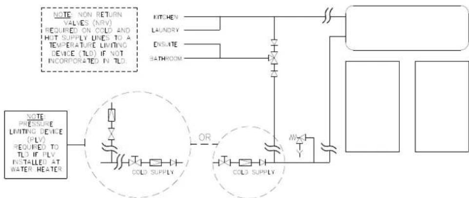
It is necessary and we recommend that a temperature limiting device be fitted between the water heater and the hot water outlets in any ablution area such as a bathroom or ensuite, to reduce the risk of scalding. The installing plumber may have a legal obligation to ensure the installation of this water heater meets the delivery water temperature requirements of AS/NZS 3500.4 so that scalding water temperatures are not delivered to a bathroom, ensuite or other ablution area.
The temperature limiting device used with a solar water heater should have a specified 'minimum temperature differential' between the hot water inlet and the tempered water outlet of no greater than 10^ C. In addition, a temperature limiting device capable of receiving a hot water supply temperature of up to 99^ C should be used in conjunction with a Rheem solar thermosiphon system. Refer to the specifications of the temperature limiting device.
Where a temperature limiting device is installed adjacent to the solar water heater, the cold water line to the temperature limiting device can be branched off the cold water line either before or after the isolation valve and pressure limiting valve to the solar storage tank, but it MUST BE before the non return valve to a direct 52L / RL series system. The cold water line to the temperature limiting device can be branched off the cold water line either before or after the non return valve to the indirect 52H / RLX series system.
If a combination isolation valve and non return valve (duo or trio valve) is installed on the cold water line to the solar water heater and the cold water line to the temperature limiting device branches off after this valve, then a second non return valve must be installed between the cold water branch and the solar storage tank of a direct 52L / RL series system.
⚠ Warning: A non return valve MUST BE installed on the cold water line to the direct 52L / RL series system solar storage tank AFTER the cold water branch to a temperature limiting device.
If an expansion control valve is required, it must always be installed after the non return valve and be the last valve prior to the solar storage tank.

flowchart
graph TD
    A["NOTE: NON RETURN VALVES (NRV) REQUIRED ON COLD AND HOT SUPPLY LINES TO A TEMPERATURE LIMITING DEVICE (TLD) IF NOT INCORPORATED IN TLD."] --> B["COLD SUPPLY"]
    B --> C["OR"]
    C --> D["COLD SUPPLY"]
    D --> E["MW"]
    E --> F["Water Heater"]
    G["NITCHEN"] --> H["Pressure Limiting Device (PLV) REQUIRED TO TLD IF PLV INSTALLED AT WATER HEATER"] --> H
    I["LAUNCHY"] --> H
    J["ENSUITE"] --> H
    K["BATHROOM"] --> H
    H --> L["Output"]
Two Temperature Zones Using a Temperature Limiting Device – Direct Solar Water Heater
flowchart
graph TD
    A["NOTE: NON RETURN VALVES (NRV)<br>REQUIRED ON COLD AND HOT SUPPLY LINES TO A TEMPERATURE LIMITING DEVICE (TLD) IF NOT INCORPORATED IN TLD."] --> B["COLD SUPPLY"]
    A --> C["KITCHEN"]
    A --> D["LAUNDRY"]
    A --> E["ENSUTE"]
    A --> F["BATHROOM"]
    G["NOTE: PRESSURE<br>LIMITING DEVICE (PLV)<br>REQUIRED TO TLD IF PLV<br>INSTALLED AT WATER HEATER"] --> H["COLD SUPPLY"]
    G --> I["OR"]
    G --> J["COLD SUPPLY"]
    H --> K["Water Heater"]
    I --> K
    J --> K
Two Temperature Zones Using a Temperature Limiting Device – Indirect Solar Water Heater
If a pressure limiting valve is installed on the cold water line to the solar water heater and the cold water line to a temperature limiting device branches off before this valve or from another cold water line in the premises, then a pressure limiting valve of an equal pressure setting may be required prior to the temperature limiting device.
CIRCULATED HOT WATER FLOW AND RETURN SYSTEM
A solar water heater should not be installed as part of a circulated hot water flow and return system in a building. The benefits of solar gain will be significantly reduced and energy gained from the sun lost through the pipe work.
If a circulated flow and return system is required, it is necessary to bypass the solar water heater and install a secondary water heater connected to the hot water flow and return line and supplied from the solar water heater. The secondary water heater must be a storage water heater able to provide a hot water outlet temperature of at least 60^ C. Note: The thermostat must always be set to at least 60^ C. Refer to the diagram on page 24.
Temperature Limiting Device
A temperature limiting device cannot be installed in circulated hot water flow and return pipe work. The tempered water from a temperature limiting device cannot be circulated. Where a circulated hot water flow and return system is required in a building, a temperature limiting device can only be installed on a dead leg, branching off the circulated hot water flow and return pipe.
If circulated tempered water were to be returned back to the water heater, depending on the location of the return line connection on the water supply line to the water heater, then either:
- water will be supplied to the cold water inlet of the temperature limiting device at a temperature exceeding the maximum recommended water supply temperature, or
- when the hot taps are closed no water will be supplied to the cold water inlet of the temperature limiting device whilst hot water will continue to be supplied to the hot water inlet of the temperature limiting device.
These conditions may result in either water at a temperature exceeding the requirements of AS/NZS 3500.4 being delivered to the hot water outlets in the ablution areas, or the device closing completely and not delivering water at all, or the device failing. Under either condition, the operation and performance of the device cannot be guaranteed.

flowchart
graph TD
    A["KITCHEN HOT WATER OUTLET"] --> B["LAUNDRY HOT WATER OUTLET"]
    B --> C["COLD SUPPLY"]
    C --> D["BATHROOM TEMPERED WATER OUTLETS"]
    D --> E["COLD SUPPLY"]
    E --> F["ENSUITE TEMPERED WATER OUTLETS"]
    F --> G["CIRCULATOR THERMOSTATICALLY OR TIMER CONTROLLED OR 24 HOUR OPERATION"]
    G --> H["ELECTRIC WATER HEATER (CONTINUOUS) 60°C (25L OR 50L)"]
    H --> I["SOLAR THERMOSYPHON WATER HEATER"]
    I --> J["COLD SUPPLY"]
    J --> K["+"]
    K --> L["+"]
    L --> M["+"]
    M --> N["SOLAR THERMOSYPHON WATER HEATER"]
    style A fill:#f9f,stroke:#333
    style B fill:#f9f,stroke:#333
    style C fill:#ccf,stroke:#333
    style D fill:#ccf,stroke:#333
    style E fill:#ccf,stroke:#333
    style F fill:#ccf,stroke:#333
    style G fill:#cfc,stroke:#333
    style H fill:#cfc,stroke:#333
    style I fill:#fcc,stroke:#333
    style J fill:#fcc,stroke:#333
    style K fill:#fcc,stroke:#333
    style L fill:#fcc,stroke:#333
    style M fill:#fcc,stroke:#333
    style N fill:#fcc,stroke:#333
Circulated Hot Water Flow and Return System – Solar Water Heater
REDUCING HEAT LOSSES
The cold water line to and the hot water line from the water heater must be insulated in accordance with the requirements of AS/NZS 3500.4. The insulation must be weatherproof and UV resistant if exposed.
The pipe work between the solar storage tank and the solar collectors may be required to be insulated. Refer to “Warning: Plumber Be Aware” on page 36.
SADDLING - PIPE WORK
To prevent damage to the cylinder when attaching pipe clips or saddles to the water heater jacket, we recommend the use of self-drilling screws with a maximum length of 13 mm. Should pre drilling be required, extreme caution must be observed when penetrating the jacket of the water heater.
Note: If the cylinder is damaged as a result of attaching pipe clips or saddles to the jacket, any resultant faults will not be covered by the Rheem warranty.
BOOSTER HEATING UNIT
The booster heating unit is for heating the water at times of low solar energy gain, such as during very cloudy or rainy weather, or during the colder months. Refer to “Connections – Electrical” on page 54 for electrical connection requirements and control options of the booster heating unit.
If this water heater is installed with an in-series booster, then the electric booster heating unit in the solar storage tank will not need to be connected to a power supply.
PLASTIC END COVER
A set plastic end covers is available for installation to the ends of the tank. These ends provide an aesthetically pleasing finish to the system by housing the pipe work and electrical connection within them.
Where a plastic end cover is to be installed, the plumbing and electrical connections need to be routed to suit. Check the installation documentation that comes with the plastic ends for these details.
TANK REPLACEMENT
If replacing a tank over 5 years old, the replacement tank must be fitted with a new temperature pressure relief valve and expansion control valve.
COLLECTOR REPLACEMENT
Care must be taken to ensure the surface area of new collectors is equal to +/- 10% that of the existing collector surface area otherwise overheating in summer or lower recovery rates in winter may occur.
OVER-TEMPERATURE PROTECTION
AS/NZS 2712:2007 includes a requirement for a no-load system operation test. In order to comply with this requirement, RL systems installed with Titan collector(s) must be fitted with TRV, and RLX systems installed with two or more Titan collectors must be fitted with OTP.
The systems listed below must be installed using the Over-Temperature Protection Parts kits described to comply with AS/NZS 2712:2007.
RL System Over-Temperature Protection
The following system requires the installation of a Thermosiphon Restrictor Valve (TRV) kit to meet the requirements of AS/NZS 2712:2007.
System Number Parts Kit No. No. of Collectors
RL11 Titan Series 2A 12105501 uses 1 collector
RL32 Titan Series 2A 12105503 uses 2 collectors
Please refer to the "System Assembly" section of this manual for full TRV installation details.
RLX System Over-Temperature Protection
The following systems require the installation of an OTP kit to meet the requirements of AS/NZS 2712:2007:
System Number Parts Kit No. No. of Collectors
RLX32 S3 Titan Series 2A 12105523 uses 2 collectors
RLX33 S3 Titan Series 2A 12105525 uses 3 collectors
Please refer to the specific RLX OTP Installation Instructions (34-7297) supplied in these OTP Parts Kits for full installation details.
DIMENSIONS AND TECHNICAL DATA

Direct System Data
| Solar Storage Tank | Solar Collectors | Pipe Kit | System | ||||||||
| Direct System | Type | Model | Nominal Capacity (litres) | Empty (kg) cartoned | Full (kg) | Model | Qty | Empty | Full | Weight (kg) | Full (kg) |
| RL11 | direct | 52L180 | 180 | 48 | 226 | Australis or Titan | 1 | 3334 | 3536 | 67 | 267269 |
| RL32 | direct | 52L300 | 300 | 72 | 367 | Australis or Titan | 2 | 6668 | 6971 | 89 | 444447 |
Technical data is subject to change.
Tank model number has a four digit suffix to denote the heating unit size and jacket colour, e.g. 52L300M775, where:
M5 = 2.4kW, M7 = 3.6kW
25 = Night Sky, 75 = Silver Grey, 80 = Woodland Grey, 94 = Headland
Indirect System Data
| Solar Storage Tank | Solar Collectors | Pipe Kit | System | ||||||||
| Indirect System | Type | Model | Nominal Capacity (litres) | Empty (kg) cartoned | Full (kg) | Model | Qty | Empty | Full | Weight (kg) | Full (kg) |
| RLX11 | indirect | 52H180 | 180 | 53 | 231 | Australis or Titan | 1 | 3334 | 3536 | 611 | 272278 |
| RLX32 | indirect | 52H300 | 300 | 78 | 373 | Australis or Titan | 2 | 6668 | 6971 | 813 | 450457 |
| RLX33 | indirect | 52H300 | 300 | 78 | 373 | Australis or Titan | 3 | 99102 | 104107 | 1016 | 487496 |
| 52H180/1S | indirect | 52H180 | 180 | 53 | 231 | S200 | 1 | 48 | 52 | 6 | 289 |
| 52H300/2S | indirect | 52H300 | 300 | 78 | 373 | S200 | 2 | 96 | 104 | 8 | 485 |
Technical data is subject to change.
Tank model number has a four digit suffix to denote the heating unit size and jacket colour, e.g. 52H300M775, where:
M5 = 2.4kW, M7 = 3.6kW
25 = Night Sky, 75 = Silver Grey, 80 = Woodland Grey, 94 = Headland
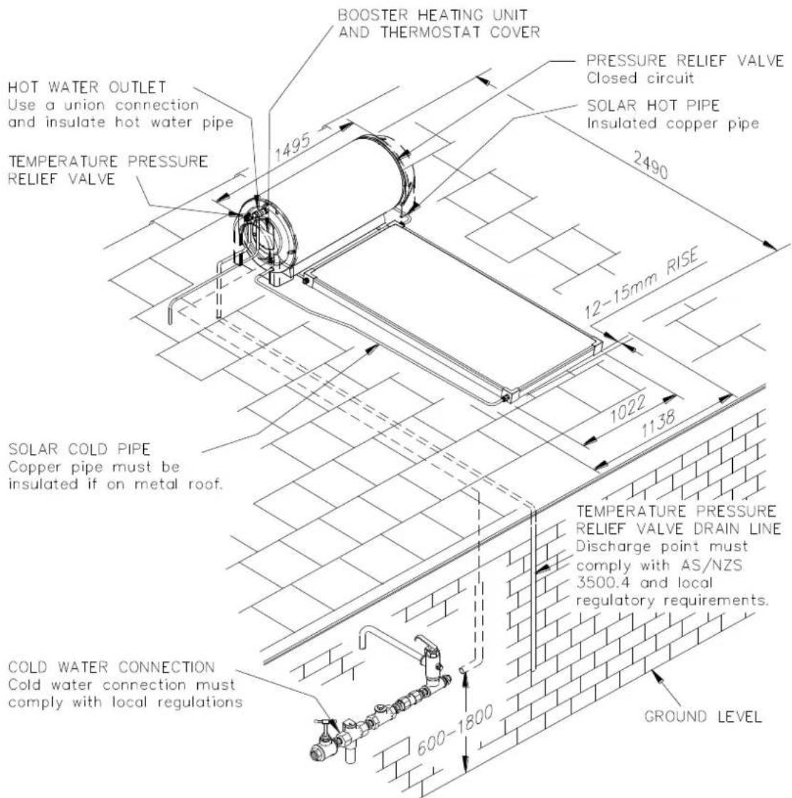
TYPICAL INSTALLATION – SOLAR THERMOSIPHON 180
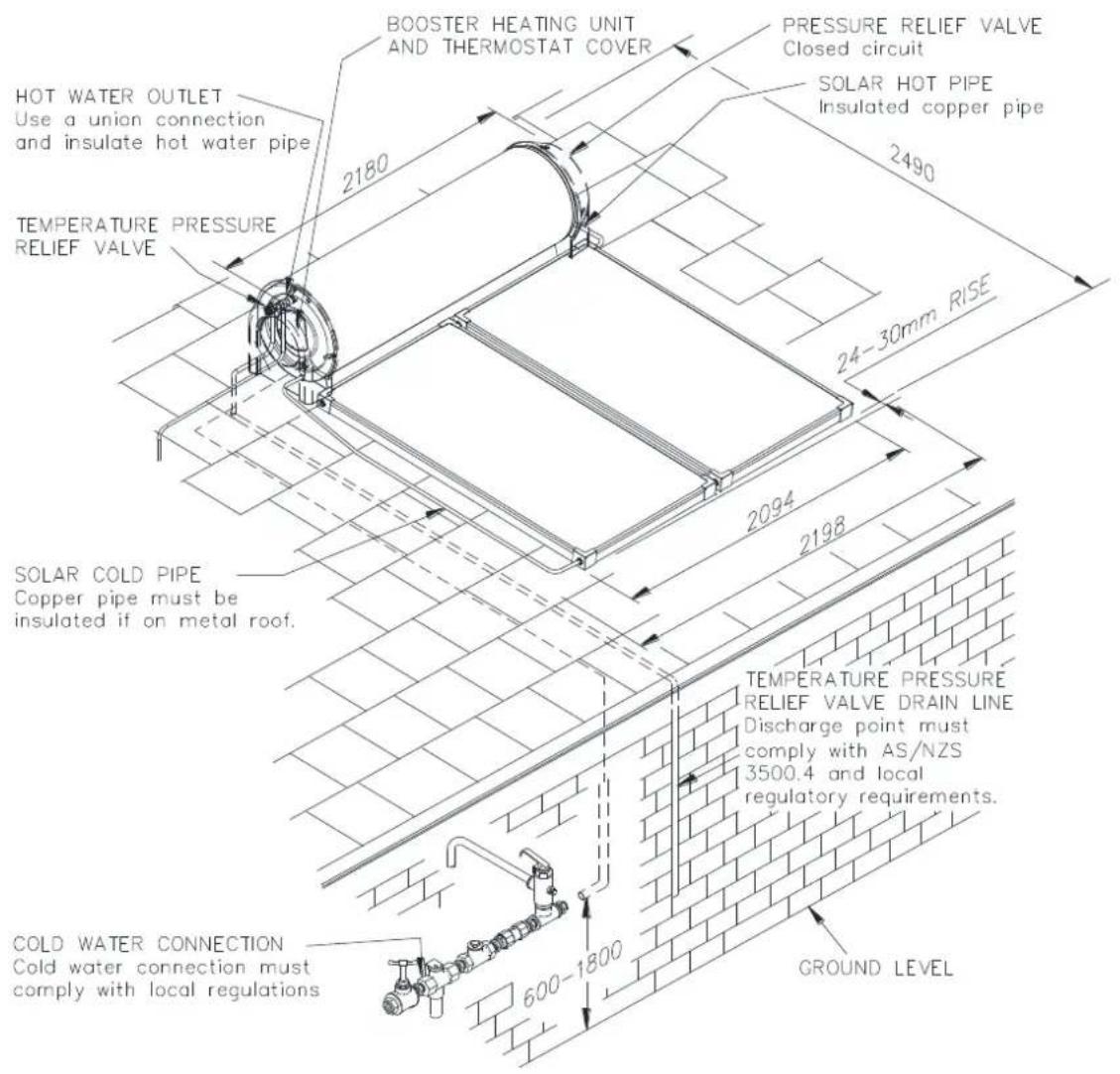
TYPICAL INSTALLATION - SOLAR THERMOSIPHON 300
ASSEMBLY DIAGRAM - 52H SERIES WITHOUT OTP - CONETITE FITTING COLLECTORS
Components
- Collector Hot Return Pipe
- HTT55-1 TPR Valve 850 kPa
- Bush Red R 34 M x Rp 12 F
- Collector Gland Nut
- Collector Union - conetite
- Retaining Clip
- H50 ECV - 700 kPa
- Brass Nipple **
- Brass T **
- Collector Clamp & Fasteners
-
Boiler Union **
-
Collector Rail
- Tank Strap
- Collector Flow Pipe
- Combination Stop, Strainer & Non-Return Valve **
- PLV 500 kPa *
- Olive Compression
- Nut Compression
- Filling Plug Assembly
- Collector Bung
-
Pressure Relief Valve 200 kPa
-
Plastic End Cover (pr) ***
- Tank to Collector Spacer
- Union R 3/4 M x DN15 Olv
- Collector Strap
* if required
** not supplied
*** optional
Note: Pressure Relief Valve 200 kPa (22) and Retaining Clip (6) are transported behind the electrical cover.

ASSEMBLY DIAGRAM - 52L, RL SERIES WITHOUT TRV - SCREWED FITTING COLLECTORS
Components
- Collector Hot Return Pipe Assy
- HTT55-1 TPR Valve 850 kPa
- Bush Red R 34 M x Rp 12 F
- M33 Collector Nut
- Collector Union
- Copper Blanking Disk
- O-ring
- H50 ECV - 700 kPa
- Brass Nipple **
- Brass T **
-
Collector Clamp & Fasteners
-
Boiler Union **
- Collector Rail
- Tank Straps
- Collector Flow Pipe
- Combination Stop, Strainer & Non-Return Valve **
- PLV 500 kPa*
- Olive Compression
- Nut Compression
-
Collector Union M33 M x G ^3/_4 F Cone
-
Plastic End Cover (pr) ***
- Tank to Collector Spacer
- Tank Union R 34 M x G 34 M Cone
- Collector Strap
* if required
** not supplied
*** optional

ASSEMBLY DIAGRAM - 52L, RL SERIES WITH TRV - SCREWED FITTING COLLECTORS
Components
- Collector Hot Return Pipe Assy
- HTT55-1 TPR Valve 850 kPa
- Bush Red R 34 M x Rp 12 F
- M33 Collector Nut
- Collector Union
- Copper Blanking Disk
- Silicone Rubber Washer
- H50 ECV - 700 kPa
- Brass Nipple **
- Brass T **
- Collector Clamp & Fasteners
-
Boiler Union **
-
Collector Rail
- Tank Straps
- Collector Flow Pipe
- Combination Stop, Strainer & Non-Return Valve **
- Pres. Limit Valve 500 kPa*
- Olive Compression
- Nut Compression
- Thermosiphon Restrictor Valve
-
Collector Union M33 M x G 34 F Cone
-
Plastic End Cover (pr) ***
- Tank to Collector Spacer
- Tank Union R 34 M x G 34 M Cone
- Collector Strap
* if required
** not supplied
*** optional
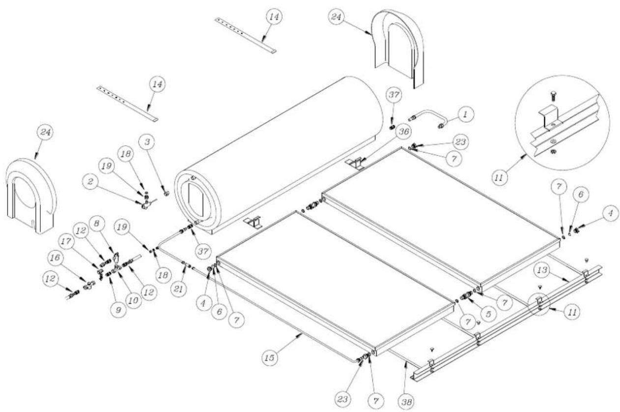
ASSEMBLY DIAGRAM – RLX SERIES WITHOUT OTP – SCREWED FITTING COLLECTORS
Components
- Collector Hot Return Pipe Assy
- HTT55-1 TPR Valve 850 kPa
- Bush Red R 34 M x Rp 12 F
- M33 Collector Nut
- Collector Union
- Retaining Clip
- O-ring
- H50 ECV - 700 kPa
- Brass Nipple **
- Brass T **
- Collector Clamp & Fasteners
- Boiler Union **
-
Collector Rail
-
Tank Straps
- Collector Flow Pipe
- Combination Stop, Strainer & Non-Return Valve **
- PLV 500 kPa *
- Olive Compression
- Nut Compression
- Boiler Tap
- M33 To 12 " BSP Reducing Bush
-
Pressure Relief Valve 200 kPa
-
Collector Union M33M x G 34 F Cone
- Plastic End Cover (pr) ***
- Copper Blanking Disk
- Tank to Collector Spacer
- Union R 3/4 M x DN15 Olv
- Collector Strap
* if required
** not supplied
*** optional
Note: Pressure Relief Valve 200 kPa (22) and Retaining Clip (6) are transported behind the electrical cover.
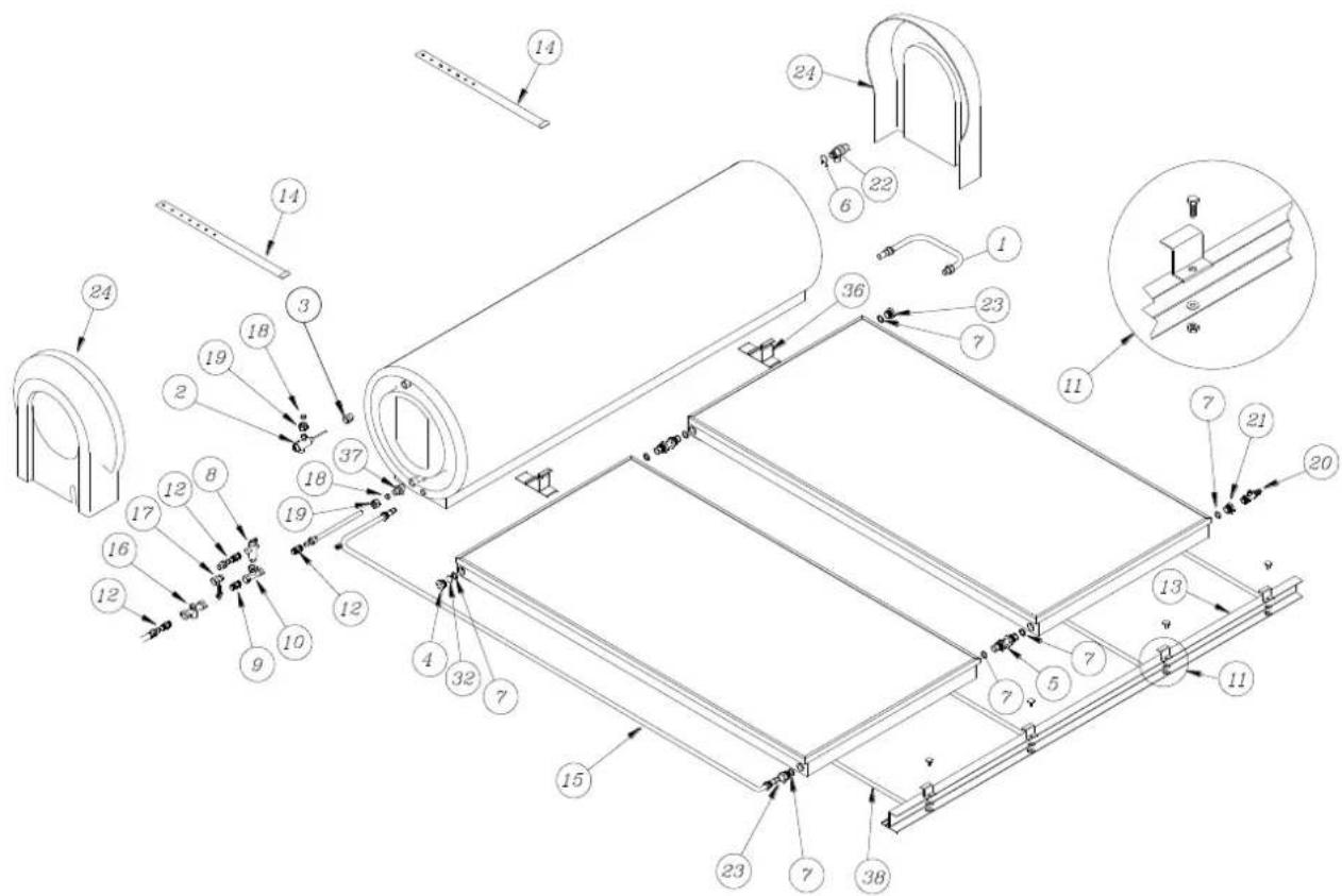
ASSEMBLY DIAGRAM – RLX SERIES WITH OTP – SCREWED FITTING COLLECTORS
Components
- Collector Hot Return Pipe
- HTT55-1 TPR Valve 850 kPa
- Bush Red R 34 M x Rp 12 F
- M33 Collector Nut
- Collector Union
- Retaining Clip
- Silicone Rubber Washer
- H50 ECV 700 kPa
- Brass Nipple **
- Brass T **
- Collector Clamp & Fasteners
- Boiler Union **
- Collector Rail
- Tank Straps
-
Collector Flow Pipe
-
Combination Stop, Strainer & Non-Return Valve **
- PLV 500 kPa *
- Olive Compression
- Nut Compression
- Boiler Tap
- M33 To 12 " BSP Reducing Bush
- PR200 Pressure Relief Valve
- Collector Union M33M x G 34 F Cone
- Plastic End Cover (pr) ***
- OTP Reservoir
- Reservoir Clamp
- Clamp Bracket
-
Tek Screw 10g-16 x 25mm
-
Flexi Hose 400 Long
- Tank To Valve Pipe
- OTP Valve
- Copper Blanking Disk
- Blanking Plug Including 'O' Ring
- Reducing Nipple
- Adaptor Including 'O' Ring
- Tank to Collector Spacer
- Union R 34 M x DN15 Olv
- Collector Strap
* if required
** not supplied
*** optional
Note: Pressure Relief Valve 200 kPa (22) and 1 x Retaining Clip (6) are transported behind the electrical cover.

The solar collectors must be installed in a shade free position. The surrounding vicinity should be checked for higher buildings or trees which may cause shade at other times of the year and for small trees which may grow and shade the solar collectors in the future.
Sufficient space should be left around the thermosiphon solar water heater to allow for safe service access.
Roof area required (excluding service and access space):
| 180 litre x 1 collector | - | 1.5 m wide x 2.5 m deep. | Weight (full) up to 289 kg approx. |
| 300 litre x 2 collectors | - | 2.5 m wide x 2.5 m deep. | Weight (full) up to 485 kg approx. |
| 300 litre x 3 collectors | - | 3.5 m wide x 2.5 m deep. | Weight (full) up to 496 kg approx. |
The installation must comply with the requirements of AS/NZS 3500.4 and all local codes and regulatory authority requirements. Refer to "System Assembly" on page 37 for the procedure to mount the system and connection details of the solar hot and solar cold pipes.
ROOF STRENGTH
The installer must ensure the structural integrity of the building is not compromised by the solar water heater installation and the roof structure is suitable to carry the full weight of the solar storage tank, solar collectors and frame (if one is installed). If in any doubt of the construction or the condition of the roof, the roof should be suitably strengthened. Consult a structural engineer.
The solar storage tanks, when full of water, weigh approximately 495 kg (300 litre) and 292 kg (180 litre). Each S200 solar collector and its fittings weighs up to approximately 60 kg when full of closed circuit fluid and each Australia and Titan solar collector and its fittings weighs approximately 43 kg when full of water.
ORIENTATION OF SOLAR COLLECTORS
To help maximise system performance, solar collectors should be installed with an optimum orientation facing true north (in the southern hemisphere) or true south (in the northern hemisphere). Always check for true north or true south using a compass or other suitable device.
The solar performance of a system reduces as the orientation of the collectors moves away from the optimum orientation, resulting in the need for increased boosting to supply the same hot water load. Solar collectors facing up to 45^ from the optimum orientation will receive about 4% to 5% less total solar radiation.
However, the optimum orientation of solar collectors is not always practical or achievable. Solar collectors may be installed up to 90^ from the optimum orientation. Where the orientation is greater than 60^ from the optimum, either an additional solar collector or selective surface collectors in lieu of non-selective surface collectors may be installed to make up for the reduction in solar performance where such an alternative is available. Each of these options should be discussed with the system owner. If neither of these options is possible nor acceptable to the system owner, then the system owner needs to be made aware of, understand and accept that increased boosting may be required to meet their hot water requirements.
Refer to “Solar Collectors” on page 19 for additional information on the selection of type of solar collectors for this system.
INCLINATION OF SOLAR COLLECTORS
To help maximise system performance, solar collectors should be installed with an optimum inclination. This is equal to 90% to 100% of the local latitude angle when collectors are oriented within 60^ of true north or true south, and between 10^ and 20^ when the collectors are oriented between 60^ and 90^ from the optimum orientation.
Generally, improved summer performance is obtained from an angle of inclination less than the optimum angle and improved winter performance is obtained by an angle of inclination greater than the optimum angle. If the angle of inclination varies by 20^ from the optimum angle, the solar collectors will receive about 10% less total annual solar radiation. The latitude of some Australian cities are listed on page 35.
However, the optimum inclination of solar collectors is not always practical or achievable. A thermosiphon solar water heater may be installed at the roof angle for simplicity of installation and appearance, but must never be less than 10^ from the horizontal.
The water heater is suitable for installations with an inclination of up to 30^ . Where the solar water heater is installed at inclinations greater than 30^ , a With Pitch frame and tank frame mounting kit are necessary. Refer to your local Solar Distributor for details.
A Fixed Pitch frame can be installed to increase the angle of inclination of the thermosiphon solar water heater. This type of frame should be used if the roof pitch is less than 10^ or varies by more than 20^ below the optimum angle. A tank frame mounting kit is also required with a Fixed Pitch frame. Refer to your local Solar Distributor for details.
The use of a Fixed Pitch frame should be discussed with the system owner. If this option is neither possible nor acceptable to the system owner, then the system owner needs to be made aware of, understand and accept that increased boosting may be required to meet their hot water requirements.
CYCLONIC OR HIGH WIND AREAS
For an installation of a thermosiphon solar water heater in a cyclonic or high wind area, a suitable With Pitch frame and a tank frame mounting kit are required. Refer to your local Solar Distributor for details.
The installation of this solar water heater with a tank frame mounting kit on a suitable frame, subject to the frame's design criteria not being exceeded:
- is suitable for installation in geographic locations up to and within Wind Region D (With Pitch frame) or up to and within Wind Region C (Fixed Pitch frame), as defined in the Building Code of Australia, Australian / New Zealand Standard AS/NZS 1170.2:2002 and the Australian Standard AS 4055-2006, or equivalent location, and
- provides an acceptable method of installation where it is necessary to satisfy the requirements of the Building Code of Australia and AS/NZS 3500.4:2003 Clause 6.5.3.4 for high wind areas, or equivalent requirements.
LATITUDE OF SOME AUSTRALIAN CITIES
WARNING: Plumber – Be Aware
- The solar hot and solar cold pipe work between the thermosiphon solar storage tank and the solar collectors are supplied in the pipe kit. The supplied copper solar hot and solar cold pipes MUST BE used.
- If the solar water heater is installed either on a metal roof or in a trafficable area, such as on an accessible roof, then the solar hot and solar cold pipes must be insulated. The solar hot and solar cold pipes may be required to be insulated to comply with local regulations.
If insulation is required, the full length of the solar hot and solar cold pipes MUST BE insulated.
The insulation must:
- be of a closed cell type or equivalent, suitable for a solar water heating application and capable of withstanding the temperature of the water or closed circuit fluid generated by the solar collectors under stagnation conditions
The specification of the chosen insulation material should be checked with the insulation manufacturer prior to installation as different materials may vary in temperature tolerance. - be at least 13 mm thick, however thicker insulation may be required to comply with the requirements of AS/NZS 3500.4
■ be weatherproof and UV resistant
■ be fitted up to and cover the connections on both the solar storage tank and the solar collectors.
The insulation will offer corrosion protection to a metal roof against water runoff over the copper pipe, assist in avoiding accidental contact with the solar pipe work as high temperature water or closed circuit fluid can flow from the solar collectors to the solar storage tank and also reduce pipe heat losses.
- Plastic pipe MUST NOT be used, as it will not withstand the temperature and pressure of the closed circuit fluid (indirect system) and water (direct system) generated by the solar collectors under stagnation conditions. The solar collectors can generate extremely high water or closed circuit fluid temperatures up to 150°C and high water pressure of 850 kPa. Plastic pipe cannot withstand these temperatures and pressures and MUST NOT be used. Failure of plastic pipe can lead to the release of high temperature closed circuit fluid and water and cause severe water damage and flooding.
- There must be a continuous fall of a minimum 10^ in the pipe work from the thermosiphon solar storage tank to the solar collectors. The highest point of the solar cold pipe and solar hot pipe must be where they connect to the thermosiphon solar storage tank, otherwise thermosiphoning will not occur.
- The solar water heater is to be isolated during the testing and commissioning of the heated water reticulation system in a building, in accordance with Clause 11.1 and 11.3 (a) of AS/NZS 3500.4.
SYSTEM ASSEMBLY
COMPONENTS AND KIT CONTENTS
The thermosiphon solar water heater is supplied with a pipe kit, which contains the components required to assemble the solar storage tank and solar collectors together. The thermosiphon pipe kits are suitable for:
12105530 52H180 tank with one S200 solar collector
12105532 52H300 tank with two S200 solar collectors
| Part No | Kit Components and Description | 12105530 one S200 collector | 12105532 two S200 collectors |
| 331847 | Collector mounting rail 1020 mm long standard | 1 | - |
| 331846 | Collector mounting rail 1650 mm long standard | - | 1 |
| 204600 | Collector strap | 2 | 2 |
| 343064 | Tank strap | 2 | 2 |
| 339210 | Valve ECV 1⁄2" H50 700 kPa | 1 | 1 |
| 344349 | Valve TPR 1⁄2" HTT55-1 850 kPa | 1 | 1 |
| 345074 | Plastic sheet black 1800 x 1220 x 100um (rolled up) | 1 | 1 |
| 344450 | Pipe cold assembly HX180 | 1 | - |
| 344452 | Pipe cold assembly HX300 | - | 1 |
| 344451 | Pipe hot assembly HX180 | 1 | - |
| 344453 | Pipe hot assembly HX300 2 collector | - | 1 |
| 337144 | Tank to collector spacer | 2 | 2 |
| 331928 | Collector clamp standard | 2 | 4 |
| 330350 | Screw set 5/16" UNC x 3⁄4" SS | 2 | 4 |
| 330806 | Nut 5/16" SS | 2 | 4 |
| 330354 | Washer 5/16" SS | 2 | 4 |
| 331658 | Union Body R3/4 M x DN15 Olv | 1 | 1 |
| 331657 | Union Body R1/2M x DN15 Olv | 2 | 2 |
| 334046 | Nipple R1⁄2 M x R1⁄2 M | 1 | 1 |
| 331656 | Olive 1/2 | 4 | 4 |
| 331666 | Tee G1⁄2 x G1⁄2 x G1⁄2 | 1 | 1 |
| 331655 | Nut Compression G1/2 | 4 | 4 |
| 337280 | Bush Reducing R3/4 M x RP1/2 F | 1 | 1 |
| 337134 | Fill plug assembly 3⁄4" conetite, consisting of:1 x 337116 gland nut1 x 337117 conetite fill fitting1 x 337130 fill plug 3⁄4"1 x 330150 fill plug gasket | 1 | 1 |
| 337135 | Collector bung assembly 3⁄4" cone, consisting of:1 x 337116 gland nut1 x 337132 collector bung 3⁄4" conetite | 1 | 1 |
| 337121 | Collector connector assembly cone type | - | 2 |
| 345094 | Insulator Valve TPR HTT55-1 | 1 | 1 |
| 347187 | Instruction to attach fill / drain label | 1 | 1 |
| 347189 | Label fill / drain | 1 | 1 |
12105520 52H180 tank with one Australis or Titan solar collector
12105522 52H300 tank with two Australis solar collectors
12105523 52H300 tank with two Titan solar collectors
12105524 52H300 tank with three Australis solar collectors
12105525 52H300 tank with three Titan solar collectors
| Part No | Kit Components and Description | 1210 5520 | 1210 5522 | 1210 5523 | 1210 5524 | 1210 5525 |
| 331847 | Collector mounting rail 1020 mm long standard | 1 | - | - | 1 | 1 |
| 331846 | Collector mounting rail 1650mm long standard | - | 1 | 1 | 1 | 1 |
| 331844 | Drive cleat | - | - | - | 1 | 1 |
| 343064 | Tank strap | 2 | 2 | 2 | 2 | 2 |
| 204600 | Collector strap | 2 | 2 | 2 | 3 | 3 |
| 339210 | Valve ECV 1⁄2" H50 700 kPa | 1 | 1 | 1 | 1 | 1 |
| 344349 | Valve TPR 1⁄2" HTT55-1 850 kPa | 1 | 1 | 1 | 1 | 1 |
| 344450 | Pipe cold assembly HX180 | 1 | - | - | - | - |
| 344452 | Pipe cold assembly HX300 | - | 1 | 1 | 1 | 1 |
| 344451 | Pipe hot assembly HX180 | 1 | - | - | - | - |
| 344453 | Pipe hot assembly HX300 2 collector | - | 1 | - | 1 | - |
| 344586 | Pipe hot assembly HX300 2 collector OTP | - | - | 1 | - | - |
| 344587 | Pipe hot assembly HX300 3 collector OTP | - | - | - | - | 1 |
| 337093 | Extension pipe assembly systems | - | - | - | 2 | 1 |
| 337144 | Tank to collector spacer | 2 | 2 | 2 | 3 | 3 |
| 331928 | Collector clamp | 2 | 4 | 4 | 6 | 6 |
| 331656 | Olive 1⁄2 | 2 | 2 | 2 | 2 | 2 |
| 331655 | Nut Compression G1/2 | 2 | 2 | 2 | 2 | 2 |
| 330600 | Gland nut M33 M | 1 | 1 | 1 | 1 | 1 |
| 330606 | Copper blanking disc | 2 | 2 | 2 | 2 | 2 |
| 344132 | Tap boiler drain | 1 | 1 | 1 | 1 | 1 |
| 337280 | Bush Reducing R3/4 M x RP1/2 F | 1 | 1 | 1 | 1 | 1 |
| 344134 | Adaptor Antifreeze M33 M x G1⁄2F | 1 | 1 | 1 | 1 | 1 |
| 330695 | Collector connector assembly screwed fitting | - | 2 | 2 | 4 | 4 |
| 344297 | Adaptor union body M33 M x G3⁄4F conetite | 2 | 2 | 2 | 2 | 2 |
| 330350 | Screw set 5/16" UNC x 3⁄4" SS | 2 | 4 | 4 | 6 | 6 |
| 330354 | Washer 5/16" SS | 2 | 4 | 4 | 6 | 6 |
| 330806 | Nut 5/16" SS | 2 | 4 | 4 | 6 | 6 |
| 345096 | Silicone rubber washer 31 x 22.5 x 2.0 | 5 | - | 10 | - | 15 |
| 347669 | Instructions caution silicone rubber washer | 1 | - | 1 | - | 1 |
| 330171 | O-ring 25 ID x 3.2 mm | 5 | 10 | - | 15 | - |
| 347674 | Instruction on Seal Selection | 1 | - | - | ||
| 331658 | Union Body R 3⁄4 M x G 1⁄2 M Olv | 1 | 1 | 1 | 1 | 1 |
| 347187 | Instruction to attach fill / drain label | 1 | 1 | 1 | 1 | 1 |
| 347189 | Label fill / drain | 1 | 1 | 1 | 1 | 1 |
| 344327 | Flexi hose 3/8 BSP F x 3/8 BSP F x 400 | - | - | 1 | - | 1 |
| 344185 | Reservoir tank 2 collectors | - | - | 1 | - | - |
| 344186 | Reservoir tank 3 collectors | - | - | - | - | 1 |
| 344399 | Mounting bracket aluminium (with adhesive tape) | - | - | 2 | - | 3 |
| 343037 | Reservoir tank SS clamp assembly | - | - | 2 | - | 3 |
| 209000 | Valve thermosiphon arrestor TA705 3⁄4 | - | - | 1 | - | 1 |
| 344573 | Connector assembly tank to OTP valve | - | - | 1 | - | 1 |
| 348085 | Screw TEK 10G – 16 TPI x 25 | - | - | 4 | - | 6 |
| 347199 | Instruction RLX S3 OTP installation | - | - | 1 | - | 1 |
| 341504 | Adaptor Tee clip in port to ISO7 RP1⁄4 & O-ring | - | - | 1 | - | 1 |
| 344593 | Adaptor G3/8" x BSP to ISO7 R1⁄4" | - | - | 1 | - | 1 |
| 088100 | Spring clip for Relief Valve Caleffi | - | - | 1 | - | 1 |
| 341515 | Plug thumb G1/8 M & O-ring assembly | - | - | 1 | - | 1 |
| 345094 | Insulator Valve TPR HTT55-1 | 1 | 1 | 1 | 1 | 1 |
12105500 52L180 tank with one Australis
12105501 52L180 tank with one Titan collector
12105502 52L300 tank with two Australis solar collectors
12105503 52L300 tank with two Titan solar collectors
| Part No | Kit Components and Description | 12105500 | 12105501 | 12105502 | 12105503 |
| 331847 | Collector mounting rail 1020mm long standard | 1 | 1 | - | - |
| 331846 | Collector mounting rail 1650mm long standard | - | - | 1 | 1 |
| 343064 | Tank strap | 2 | 2 | 2 | 2 |
| 204600 | Collector strap | 2 | 2 | 2 | 2 |
| 339210 | Valve ECV 1⁄2" H50 700 kPa | 1 | 1 | 1 | 1 |
| 344349 | Valve TPR 1⁄2" HTT55-1 850 kPa | 1 | 1 | 1 | 1 |
| 341682 | Pipe cold assembly RL180 DN20 | 1 | - | - | - |
| 331683 | Pipe cold assembly RL300 DN20 | - | - | 1 | - |
| 341680 | Pipe hot assembly RL180 DN20 | 1 | 1 | - | - |
| 341681 | Pipe hot assembly RL300 DN20 | - | - | 1 | 1 |
| 341685 | Pipe cold assembly lower RL180 DN20 TRV | - | 1 | - | - |
| 341687 | Pipe cold assembly lower RL300 DN20 TRV | - | - | - | 1 |
| 341686 | Pipe cold assembly upper DN20 TRV | - | 1 | - | 1 |
| 337144 | Tank to collector spacer | 2 | 2 | 2 | 2 |
| 331928 | Collector clamp | 2 | 2 | 4 | 4 |
| 337280 | Bush Reducing R3/4 M x RP1/2 F | 1 | 1 | 1 | 1 |
| 344298 | Union Body R 3⁄4 M x G 3⁄4 M Con | 2 | 2 | 2 | 2 |
| 344395 | Valve thermosiphon resistor - Conetite | - | 1 | - | 1 |
| 344297 | Adaptor union body M33 M x G 3⁄4 F conetite | 2 | 2 | 2 | 2 |
| 331655 | Nut compression G1⁄2 | 2 | 2 | 2 | 2 |
| 331656 | Olive 1⁄2" | 2 | 2 | 2 | 2 |
| 330600 | Gland nut M33 M | 2 | 2 | 2 | 2 |
| 330606 | Copper blanking disc | 3 | 3 | 3 | 3 |
| 330695 | Collector connector assembly screwed fitting | - | - | 2 | 2 |
| 330350 | Screw set 5/16" UNC x 3⁄4" SS | 2 | 2 | 4 | 4 |
| 330354 | Washer 5/16" SS | 2 | 2 | 4 | 4 |
| 330806 | Nut 5/16" SS | 2 | 2 | 4 | 4 |
| 345096 | Silicone rubber washer 31 x 22.5 x 2.0 | - | 5 | - | 10 |
| 347669 | Instructions caution silicone rubber washer | - | 1 | - | 1 |
| 330171 | O-ring 25 ID x 3.2 mm | 5 | - | 10 | - |
| 345094 | Insulator Valve TPR HTT55-1 | 1 | 1 | 1 | 1 |
Refer to the assembly diagrams on pages 29 to 33 for the location and position of components.
DO NOT MODIFY THESE PARTS IN ANY WAY.
Notes:
- All plumbing work must be carried out by a qualified person. The installation is to be in accordance with the requirements of the Standard AS/NZS 3500.4, and all local codes and regulatory authority requirements. In New Zealand, the installation must conform with Clause G12 of the New Zealand Building Code.
- Pipe work, including that within the roof space, is to be securely fixed to prevent vibration.
- These solar collectors have passed the AS/NZS 2712 requirements for resistance to hailstone damage, so it is not normally necessary to fit a guard to a collector. Stone Guards are available to provide a level of protection to the collectors against vandalism or accidental damage. Refer to your local Solar Distributor for details.
- The Rheem warranty DOES NOT cover breakage of solar collector glass. Check your insurance policy covers collector glass breakage.
⚠ Warning: No attempt should be made to remove or replace broken collector glass.
The collector glass is not offered as a replacement part. Should the solar collector require replacement, contact your local Solar Distributor for details.
- Warning: Do not remove the solar collector packaging completely, prior to the installation as the solar collector surface can become very hot. Remove only sufficient packaging material to enable the installation of the solar collectors.
⚠ Warning: Upon completion of the installation it is necessary to leave the solar collector packaging covering the glass and fittings on an Australis or Titan solar collector. The packaging should not be removed until the solar water heater has been commissioned and is ready for use, otherwise damage to the O-rings or silicone rubber washers in the connections to the solar collector can occur.
Upon completion of the installation of the solar water heater the packaging material may be removed from the S200 solar collectors, whether or not the solar water heater is commissioned.
The solar collector packaging must be removed completely prior to the permanent operation of the water heater.
- All connectors, end plugs, O-rings, silicone rubber washers, brass fittings, collector straps, collector angle or rail, and temperature pressure relief valve required for the installation are included with the pipe kit.
Suitable screws or anchors will be required to fix the collector straps to the rafters for a pitched roof installation.
⚠ Warning: Where straps, frames, etc. are secured to roof members, all fixings must be of an appropriate type to suit the type of member. Inadequate or inappropriate fixings may result in straps becoming unsecured and the installation of the solar hot water system becoming unsafe.
- All olive compression fittings must use brass or copper olives.
- Use thread sealing tape or an approved thread sealant on all other but the conetite, O-ring and silicone rubber washer fittings.
- If the solar storage tank is being installed with existing solar collectors, then utilise the existing fittings and pipes used on the installation. If the tank being replaced is over five years old, then a new temperature pressure relief valve and expansion relief valve must be installed.
Refer to the installation instructions supplied with the RLX system OTP kit for additional information of the installation of the over temperature protection components.
-
Roof Condition: Check the condition of the roof and advise the client of any broken tiles or damaged roof sheeting.
-
Solar Frame: If a solar frame is to be installed, determine the location of the frame. Assemble and fix the frame to the roof, following the installation instructions provided with the frame.
Depending upon the positioning of the frame on the roof and any minor fall the roof may have, ensure the collector rail is either horizontal or is higher on the hot outlet side of the solar collectors. If in doubt use a spirit level.
- Water Heater Location: Select a suitable position for the solar water heater.
Refer to “Solar Water Heater Storage Tank Location” on page 21 and “Solar Collector Location” on page 34.
- Position of Tank: Select the position of the solar storage tank so the front of the foot is toward the nose of an even row of tiles or even metal roof sheet above a roof batten. The rear of the foot may be seated over the nose of the tiles on the next row behind. Where possible, the tank should be positioned at least three tiles from the ridge capping to prevent disturbance of the ridge.
5. Collector Mounting Rail Preparation
Hook the Collector Straps to the Collector Mounting Rail before fixing the strap to the rafters following the steps below.
5.1 If more than two collectors are installed, locate the additional collector rail(s) adjacent to the first collector rail and join together using drive cleat supplied in the parts kit.
5.2 Determine which slots in the collector rail will be used for the collector straps after locating the rafters and taking note of the rafter spacing.
| Rafter spacing | Recommended slots | |
| One collector(1 x one collector rail) | Two collectors(1 x two collector rail) | |
| 300 mm (12") | 1, 4 or 2, 3 | 1, 6 or 2, 5 |
| 400 mm (16") | 1, 4 | 1, 5 or 2, 6 |
| 450 mm (18") | 1, 4 | 2, 5 |
| 500 mm (20") | 1, 4 | 1, 6 or 2, 5 |
| 600 mm (24") | 2, 3 | 1, 5 or 2, 6 |
| 900 mm (36") | 1, 4 | 2, 5 |

collector rail – one collector

collector rail – two collectors
| Rafter spacing | Recommended slotsThree collectors(1 x two and 1 x one collector rails) |
| 300 mm (12") | 1, 5 (long) & 3 (short) |
| 400 mm (16") | 1, 5 (long) & 3 (short) |
| 450 mm (18") | 2, 5 (long) & 4 (short) |
| 500 mm (20") | 1, 6 (long) & 4 (short) |
| 600 mm (24") | 1, 5 (long) & 3 (short) |
| 900 mm (36") | 1, 4 (long) & 4 (short) |
5.3 Noting the orientation of the collector strap's folded end:
Slide the long straight end of the collector strap through the appropriate slot from the underside of the collector mounting rail as shown on the left side picture.
Pull the collector strap through until the first bend in the strap slips into the slot in the collector rail. The strap will engage with the collector rail as shown on the right side picture.

natural_image
Pure technical line drawing of a mechanical part or bracket (no text or symbols)
natural_image
Pure technical line drawing of a mechanical bracket or bracket (no text or symbols)6. Collector Mounting Rail Installation:
Determine the location of the collector mounting rail. Measure down the roof 2070 mm from the position of the foot of the solar storage tank to determine the location of the collector mounting rail.
Note: The solar collectors must be installed at an angle from the horizontal. Use a spirit level to determine the horizontal. Ensure the end of the collector mounting rail at the right hand outlet side of the solar collectors is between:
■ 12 – 15 mm (for one solar collector), or
■ 24 – 30 mm (for two solar collectors), or
- 36 – 45 mm (for three collectors) higher up the roof from the horizontal than the left hand end of the collector mounting rail at the inlet side of the solar collectors.
This is to ensure there is sufficient angle rise from left to right to achieve thermosiphon operation. Failure to adhere to this requirement may result in reduced solar performance from the solar water heater.
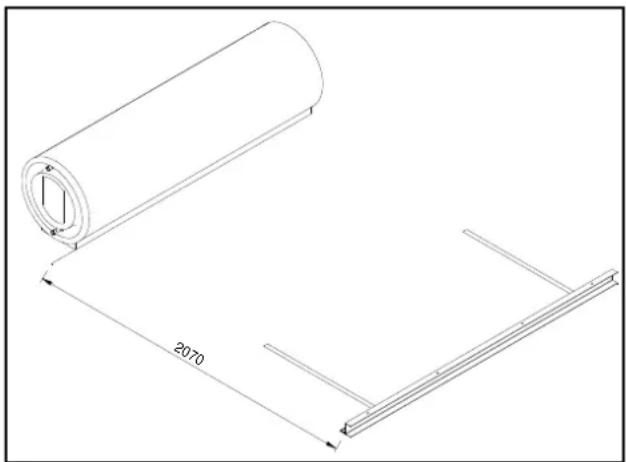
natural_image
Technical line drawing of a rolled metal sheet with a 2070mm dimension label (no text or symbols beyond the dimension)
If the roof material is not even where the collectors are to be installed, then it may be necessary to add 10 mm for each collector in the array to the above distances. It is important that the solar hot outlet is the highest point in the collector waterway so the system functions efficiently.
Tile Roof: Remove the tiles on the next row above the position of the collector mounting rail to expose the rafters. Ensure the collector mounting rail is at the correct angle from the horizontal. Once in position, fix the collector straps to the rafters, using suitable screws or anchors. Replace the tiles.
Metal Roof: Ensure the collector mounting rail is at the correct angle from the horizontal. Once in position, fix the collector straps to the rafters, through the metal roofing material, using suitable screws or anchors. Care should be taken not to mark Colorbond ^® or other metal roof sheet with a marking pen and to remove all swarf from the metal roof as these can cause deterioration of the metal roofing material.
Note: Fixings must penetrate only through the high point in the roof material profile.

- Solar Collectors: Position the solar collectors in the correct configuration with the lower ends seated in the collector mounting rail.

NOTE ON SCREWED FITTING CONNECTIONS
A connection with a screwed fitting uses either an O-ring or a silicone rubber washer for sealing.
Australis collector screwed fitting – use an O-ring (supplied in all standard non TRV / OTP kits).
Titan collector screwed fitting – use a silicone rubber washer (supplied in TRV / OTP kits and single collector kits for indirect system).
Identification of the collector type can be found on the label attached on the side of the collector body.

natural_image
Two 3D-rendered rings of varying thickness, no text or symbols present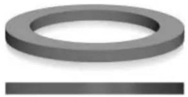
natural_image
3D rendered ring and rectangular block (no text or symbols)O-Ring (round profile) Rubber washer (flat profile)
- Collector Unions: For a 300 model with two or three solar collectors, couple the solar collectors together using the M33 collector unions and O-rings or silicone rubber washers (screwed fitting collectors only) or conetite collector unions (conetite collector) supplied in the pipe kit.

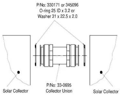
Conetite collector connection Screwed collector connection Collector Union Assembly
- Clamps and Fixing Collector (Bottom): Ensure the solar collectors are well seated and centred in the collector mounting rail.
Collector Rail: Loosely clamp the solar collectors (two clamps per collector) to the collector mounting rail, using the clamps and hex screws, washers and nuts provided.

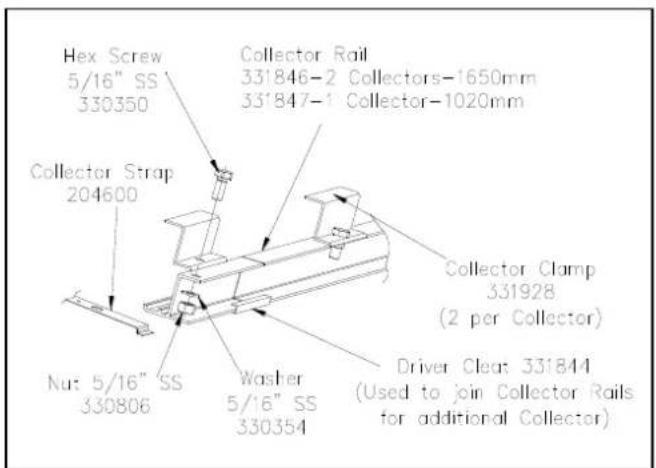
10. Tank to Collector Spacers and Solar Storage Tank:
Tile Roof: If used, fit the tank flashing sheet under the top of the solar collectors and extend up the roof to the top of the solar storage tank location. Lift the roof tiles immediately above the solar storage tank location and secure the flashing sheet to the roofing members. Ensure the flashing sheet makes the section of roof under the tank waterproof. Locate the Tank to Collector spacers against the top end of the solar collectors (one per collector).
Metal Roof: Locate the Tank to Collector spacers against the top end of the solar collectors (one per collector).
Solar Frame Installation: Ensure the solar collectors are well seated and centered in the tank / collector rail.
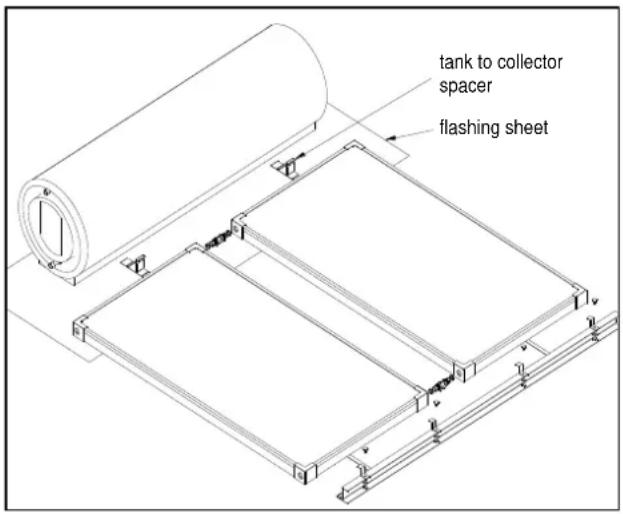
Position the solar storage tank in place above the Tank to Collector spacers or tank / collector mounting rail if the installation is on a solar frame. Centre the solar storage tank before commencing interconnecting pipe installations.
- TRV or OTP System Connection: If a Thermosiphon Restrictor Valve (TRV) is to be fitted to an RL system, assemble the cold pipe with the TRV thermostat element pointing towards the tank as per marking. If an Over Temperature Protection (OTP) fitted to an RLX system, refer to the installation instructions supplied with the kit for additional information of the installation of the over temperature protection components.
12. Tank to Collector Connections of Pipe Work:
52L / RL direct system: Fit union body R3/4 x G3/4 M with its internal cone profile facing out, one into tank socket inlet on the left hand end of the solar storage tank and one into tank socket return connection on the right hand end of the solar storage tank. Fit collector union M33 M x G3/4 F one into collector cold inlet at the bottom left hand side of the first collector and another into hot outlet at the top right hand side of the second collector for two collector systems.


Solar cold pipe: Connect the solar cold pipe to the unions on the left hand end of the solar storage tank and collector simultaneously. Push pipe against the tank union stop and hand tighten the gland nut there. Ensure the pipe is parallel with the collector. Hand tighten the gland nut at the collector. Fully tighten both ends of the solar cold pipe.
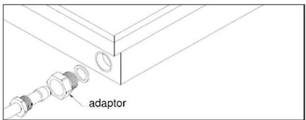
Solar hot pipe: Connect the solar hot pipe to the fitted union body on the right hand end of the solar storage tank and collector simultaneously. Push pipe against the tank union stop and hand tighten the gland nut there. Ensure the pipe is parallel with the collector. Hand tighten the gland nut at the collector. Fully tighten both ends of the solar hot pipe.
52H / RLX indirect system: Union body to tank socket is not required for the indirect system. Fit collector union M33 M x G3/4 F one into collector cold inlet at the bottom left hand side of the first collector and another into hot outlet at the top right hand side of the second collector for two collector systems. Note that collector union is not required for S200 collector.
Solar cold pipe: Connect the solar cold pipe to the heat exchanger connection on the left hand end of the solar storage tank and collector simultaneously. Push pipe against the tank socket sealing face and hand tighten the gland nut there. Ensure the pipe is parallel with the collector. Hand tighten the gland nut at the collector. Fully tighten both ends of the solar cold pipe.
Solar hot pipe: Connect the solar hot pipe to the heat exchanger connection on the right hand end of the solar storage tank and collector simultaneously. Push pipe against the tank socket sealing face and hand tighten the gland nut there. Ensure the pipe is parallel with the collector. Hand tighten the gland nut at the collector. Fully tighten both ends of the solar hot pipe.


After connecting the tank to collector pipe work, tighten the nuts on the clamps at the collector rail to secure the solar collectors.
13. Fill Plug (Indirect System Only):
52H indirect system conetite collectors: Fit the fill plug to the bottom right connection of the solar collectors using the collector gland nut provided.
RLX indirect system screwed fitting collectors: Fit the M33 / 1/2" reducing bush and boiler tap supplied to the bottom right connection of the solar collectors using the O-ring or silicone rubber washer provided.
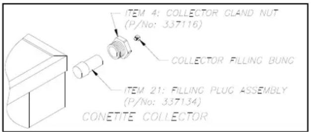
- Fill / Drain Label: 52H / RLX indirect system: Attach the Fill / Drain label adjacent to the side of the solar collector to the Fill Plug / Boiler Tap.
15. Collector Bung / End Plugs:
52H indirect system – conetite fitting: Fit the collector bung to the top left connection of the solar collector using the collector gland nut provided.
RL direct and RLX indirect system: Fit the blanking discs with either O-rings or silicone rubber washers to the top left and bottom right connections of the solar collectors using the M33 collector nut provided. The blanking disc should be installed with the smooth edge facing into the collector.

- Tank Straps: On a pitched roof installation, position and hook the tank straps into the louvers at the back and underneath of the tank support foot.
Tile Roof: Remove the tiles on the next row above the position of the solar storage tank to expose the rafters. Once in position, fix the tank straps to the rafters using suitable screws or anchors. Replace the tiles.

Metal Roof: once in position, fix the tank straps to the rafters, through the metal roofing material, using suitable screws or anchors. The tank straps may be cut to a length of approximately 400 mm to retain the aesthetics of the installation.
Note: Fixings must penetrate only through the high point in the roof material profile.
Refer to "Installation Check List" on page 50.
- Pressure Relief Valve: 52H/RLX indirect system: Fit the 200 kPa pressure relief valve to the top connection on the right hand side of the solar storage tank using the retaining clip provided.
The pressure relief valve and retaining clip are transported behind the electrical cover at the left hand end of the tank.

- Cold Water Inlet: 52L / RL direct system: Connect the copper cold supply pipe to the shoulder of the solar cold pipe using the G ^1/2 compression nut and copper olive provided.
52H / RLX indirect system: Connect the copper cold supply pipe to the cold water inlet using the Union Body R3/4 M x DN15 Olv provided.
- Hot Water Outlet: Fit the Reducing Bush (R3/4 M x RP1/2 F) to the hot water outlet.
Screw the temperature pressure relief valve into the Reducing Bush at the hot water outlet.
Orientate the hot outlet of the temperature pressure relief valve toward the rear of the tank and away from the electrical cover. The valve drain connection on the opposite side of the valve will be orientated forwards and shall be horizontal or slightly downward to permit drainage. The hot water pipe work and drain line from the temperature pressure relief valve must not prevent access to the electrical cover of the water heater.

- Insulation of the temperature pressure relief valve: Fit the insulation provided to the TPR valve. Ensure the lever of the TPR valve is accessible after strapping the insulation.
- Protective Film: Peel the protective plastic film from the solar storage tank and the solar collectors. The protective plastic will bake on and deteriorate if exposed to sunlight, reducing the aesthetics of the installation and become difficult to remove.
-
Installation Check List: Refer to the "Installation Check List" on page 50 prior to making the plumbing connections and filling the system with water.
-
Plumbing and Electrical Connections: Refer to “Connections – Plumbing” on page 51 for details on the cold water and hot water plumbing and “Connections – Electrical” on page 54 for details on the electrical connection.
Notes:
■ Penetrations through the roofing material must be:
➢ at the high point of the roof tile or metal sheet;
made neatly and kept as small as practicable;
- waterproofed upon installation of the hot and cold pipes.
- Exposed pipe work between the solar storage tank and the penetrations through the roofing material should be kept to a minimum to maintain the aesthetics of the installation.
- Closed Circuit Filling: 52H / RLX indirect system: Refer to "Closed Circuit Fluid" on page 60 for details on filling the closed circuit with the closed circuit fluid.
Asbestos Roofs
All Occupational Health and Safety matters / procedures must be adhered to in relation to asbestos material. If safety procedures are not adhered to then terminal illness may result from the handling of asbestos.
Care needs to be taken when fixing straps to asbestos roofs. It is suggested that longer Tek screws are used to fit securely into purlins.
Pitch roofs - Greater than 30°
The solar water heater must not be installed on a roof with a pitch greater than 45^ .
For installations on a roof with a pitch between 30^ and 45^ , the water heater is to be installed on a With Pitch frame.
INSTALLATION CHECK LIST
Once the installation is completed and before the tank is full of water and the collector circuit is full of heating fluid, it is IMPORTANT to check the following:
- The solar hot and solar cold pipes grade downwards with a continuous fall of not less than 10^ from the solar storage tank to the solar collectors. If in doubt use a spirit level.
- On a pitched roof installation without a frame, the hot outlet side of the collector array is between
■ 12 – 15 mm (for one solar collector), or
■ 24 – 30 mm (for two solar collectors), or
■ 36 – 45 mm (for three solar collectors)
higher up the roof from the horizontal than the solar cold side of the collector array. If in doubt use a spirit level.
- On a frame installation, depending upon the positioning of the frame on the roof and any fall the roof may have, ensure the collector mounting rail is either horizontal or is higher on the hot outlet side of the solar collectors. If in doubt use a spirit level.
All plumbing work must be carried out by a qualified person and in accordance with the requirements of the Standard AS/NZS 3500.4, and all local codes and regulatory authority requirements. In New Zealand, the installation must conform with Clause G12 of the New Zealand Building Code.
⚠ Warning: Certain types of plastic pipe, such as Poly-butylene pipe, are not suitable to be used as a hot water pipe between:
- this water heater and a temperature limiting device, and
- this water heater and a hot water outlet if a temperature limiting device is not installed.
This water heater can produce water at a temperature and pressure which can exceed the performance limits of these types of pipe. This may result in pipe failure leading to severe water damage to the property. If one of these types of plastic pipe is used as a hot water pipe in the property, then a temperature limiting device must be installed between the water heater and this pipe work.
Note: The solar storage tank of a solar water heater should not be installed as part of a circulated hot water flow and return system in a building. The benefits of solar gain will be significantly reduced and energy gained from the sun lost through the pipe work. If a circulated flow and return system is required, it is necessary to connect the return line after the solar storage tank and prior to the in-series water heater supplied from the solar water heater. Refer to “Circulated Hot Water Flow and Return System” on page 24.
CONNECTION SIZES
| 52L / RL series system | 52H / RLX series system | |
| Hot water connection: | DN15 copper tube to DN15 olive compression fitting on TPR valve | DN15 copper tube to DN15 olive compression fitting on TPR valve |
| Cold water connection: | DN15 copper tube to DN15 olive compression fitting on solar cold pipe | DN15 copper tube to R3/4 x DN15 olive union |
| Relief valve connection: | Rp 1/2 | Rp 1/2 |
WATER INLET AND OUTLET
All pipe work must be cleared of foreign matter before connection and purged before attempting to operate the water heater. All olive compression fittings must use brass or copper olives. Use thread sealing tape or approved thread sealant on all fittings.
An isolation valve and non return valve must be installed on the cold water line to the water heater. An acceptable arrangement is shown in the diagram and on page 58 for multiple installations. Refer also to "Hot Water Delivery" on page 23 and to "Mains Water Supply" on page 21.
The cold water isolation valve and expansion control valve, if one is installed, must be accessible from ground or floor level. A position of up to 1800 mm above ground or floor level is recommended. They must not be installed either on the roof or in the ceiling space, unless it is an accessible trafficable area. Extend the cold water line to the cold water inlet fitting on the solar storage tank.

A disconnection union must always be provided at the cold water inlet and hot water outlet of the water heater to allow for disconnection of the water heater.
The pipe work from the hot water outlet must not be installed in front of or prevent access to the electrical cover of the water heater.
Pipes must not be installed in direct contact with metal roofs. Where it is necessary to run piping across a metal roof, it must be fixed above the roof and surrounded with a weatherproof insulation of a minimum thickness in accordance with Clause 4.12.3 of AS/NZS 3500.4. The insulation must be UV resistant if exposed. The insulation is to assist in freeze protection and to protect the metal roof against corrosion by water runoff over the copper pipe. Consideration should be made for thermal expansion and contraction of the roof material.
Exposed pipe work between the solar storage tank and the penetrations through the roofing material should be kept to a minimum to maintain the aesthetics of the installation.
Notes:
- Penetrations through the roofing material must be:
■ at the high point of the roof tile or metal sheet;
■ made neatly and kept as small as practicable;
■ waterproofed upon installation of the hot and cold pipes.
PIPE SIZES
To achieve true mains pressure operation, the cold water line to the water heater should be the same size or bigger than the hot water line from the water heater.
The pipe sizing for hot water supply systems should be carried out by persons competent to do so, choosing the most suitable pipe size for each individual application. Reference to the technical specifications of the water heater and local regulatory authority requirements must be made.
IN-SERIES BOOSTER (IF INSTALLED)
The pipe work between the solar storage tank and an in-series booster has a minimum recommended pipe size of DN20, MUST BE of copper and be fully insulated with a closed cell type insulation or equivalent and in accordance with the requirements of AS/NZS 3500.4.
The insulation must be weatherproof and UV resistant if exposed. The insulation must be fitted up to the connections on both the solar storage tank and the in-series booster.
An isolation valve must be installed on the water line to the in-series booster. The isolation valve must be of a full flow type if the in-series booster is a continuous flow water heater.
TEMPERATURE PRESSURE RELIEF VALVE
The temperature pressure relief valve is supplied in the pipe kit. The temperature pressure relief valve must be fitted to the hot water outlet before the water heater is operated. Before fitting the relief valve, make sure the probe has not been bent. Seal the thread with Teflon tape - never hemp. Make sure the tape does not hang over the end of the thread.
Screw the valve into the correct opening (refer to the installation diagrams on pages 27 to 33). Do not use a wrench on the valve body. A copper drain line must be fitted to the temperature pressure relief valve (refer to "Relief Valve Drain" on page 53).
The valve must be insulated with closed cell polymer insulation or similar (minimum thickness 9 mm) and the insulation installed so as not to impede the operation of the valve. The insulation must be weatherproof and UV resistant if exposed.
EXPANSION CONTROL VALVE
An expansion control valve is supplied in the pipe kit and must be installed. Install the expansion control valve using a brass Tee, brass union and brass nipple on the cold water line to the water heater.
Local regulations may make it mandatory to install an expansion control valve (ECV) in the cold water line to the water heater. In other areas, an ECV is required if the saturation index is greater than +0.4 (refer to "Water Supplies" on page 13).
The expansion control valve must always be installed after the non return valve and be the last valve installed prior to the water heater (refer to diagrams on page 51). A copper drain line must be fitted to the expansion control valve (refer to "Relief Valve Drain" on page 53).
The expansion control valve and it's easing gear must be accessible from ground or floor level. A position of up to 1800 mm above ground or floor level is recommended. It must not be installed either on the roof or in the ceiling space, unless it is an accessible trafficable area. Extend the cold water line from the expansion control valve to the cold water inlet fitting on the water heater.
The valve must be insulated with closed cell polymer insulation or similar (minimum thickness 9 mm) and the insulation installed so as not to impede the operation of the valve. The insulation must be weatherproof and UV resistant if exposed.
RELIEF VALVE DRAIN
DN15 copper drain lines must be fitted to the temperature pressure relief valve and expansion control valve to carry the discharge clear of the water heater. Connect the drain lines to the valves using disconnection unions. The drain line from the valve to the point of discharge should be as short as possible, have a continuous fall all the way from the water heater to the discharge outlet and have no tap, valves or other restrictions in the pipe work.
The drain line from the temperature pressure relief valve also must not be installed in front of or prevent access to the electrical cover of the water heater.
A drain line from a relief valve must comply with the requirements of AS/NZS 3500.4.
A drain line must be no longer than 9 metres with no more than three bends greater than 45^ before discharging at an outlet or air break. The maximum length of 9 metres for a drain line is reduced by 1 metre for each additional bend required of greater than 45^ , up to a maximum of three additional bends. Where the distance to the point of final discharge exceeds this length, the drain line can discharge into a tundish.
Subject to local regulatory authority approval, the drain lines from the temperature pressure relief valve and expansion control valve from an individual water heater may be interconnected.
The outlet of a drain line must be in such a position that flow out of the pipe can be easily seen, but arranged so discharge will not cause injury, damage or nuisance. The termination point of a drain line must comply with the requirements of AS/NZS 3500.4. Drain lines must not discharge into a safe tray. A discharge pipe connected to the pressure-relief valve device is to be installed in a continuously downward direction and in a frost-free environment. In locations where water pipes are prone to freezing, drain lines must be insulated, must not exceed 300 mm in length and are to discharge into a tundish through an air gap of between 75 mm and 150 mm.
If a drain line discharges into a tundish, the drain line from the tundish must be not less than DN20. The drain line from a tundish must meet the same requirements as for a drain line from a relief valve.
Where a drain line crosses over a metal roof, the pipe work must be fully insulated with weatherproof lagging to offer corrosion protection to the metal roof against water runoff over the copper pipe. The insulation must be UV resistant if exposed.
For multiple installations the drain lines from several water heaters can discharge into a common tundish (refer to “Multiple Installations” on pages 57 and 58).
⚠ Warning: As the function of the temperature pressure relief valve on this water heater is to discharge high temperature water under certain conditions, it is strongly recommended the pipe work downstream of the relief valve be capable of carrying water exceeding 93°C. Failure to observe this precaution may result in damage to pipe work and property.
The power supply to the water heater must not be switched on until the water heater is filled with water and a satisfactory megger reading is obtained.
All electrical work and permanent wiring must be carried out by a qualified person and in accordance with the Wiring Rules AS/NZS 3000 and all local codes and regulatory authority requirements.
If this water heater is installed with an in-series booster, then the electric booster heating unit will not need to be connected to a power supply and the references to the electric booster heating unit, thermostat and boosting controls in these installation instructions will not be applicable to the installation.
Note: AS 3498 requires that a water heater provides the means to inhibit the growth of Legionella bacteria in potable water. This water heater can satisfy this AS 3498 requirement provided the electric booster is energised for a sufficient period each day and the electric booster thermostat setting is 60^ C or higher.
SOLAR STORAGE TANK
The solar storage tank with an electric booster heating unit must be directly connected to a 240 V AC 50 Hz mains power supply with an isolating switch installed at the switchboard.
A flexible 20 mm conduit is required for the electrical cable to the solar storage tank. The conduit is to be connected to the unit with a 20 mm terminator. Connect the power supply wires directly to the terminal block and earth tab connection, ensuring there are no excess wire loops inside the front cover.
The water heater is most suited for the booster heating unit to be connected to either a continuous, or a time of use, or an extended Off-Peak (overnight and day) electricity supply. A timer can also be used to control the boosting periods and help maximise solar savings. Refer to “Booster Control” on page 55.
The booster heating unit may be connected to an Off-Peak (overnight) electricity supply, however this will only allow the booster to heat the water overnight. If this type of connection is considered, care must be taken to ensure there is sufficient boost capacity to meet the household's full day and night's hot water supply during periods of no or low solar gain, particularly in cold weather. There is also an increased risk of temperature run down occurring, particularly in cooler weather (refer to "Temperature Run Down" on page 7).
Discuss the power supply requirements with the householder.
THERMOSTAT SETTING
The thermostat is adjustable from 60^ C to 70^ C. The thermostat is adjusted by turning the adjuster anticlockwise to decrease the temperature setting and clockwise to increase the temperature setting. Only adjust the temperature setting when the isolating switch is switched off at the switchboard.
For reasons of safety and economy, we advise the thermostat be set at the lowest temperature that will provide sufficient hot water during periods when boosting is required. Rheem recommends the thermostat is set at 60^ C to maximise solar contribution. Discuss the thermostat setting requirements with the householder.
BOOSTER CONTROL
The isolating switch installed in the electrical meter box for the solar storage tank should be left switched on.
Leaving the isolating switch switched on will also provide a sufficient period of time each day for the booster heating unit to operate, if required, to satisfy the requirements of AS 3498.
Timer Control Switch
A suitably rated timer control switch can be installed and will help maximise energy savings with an electrically boosted solar water heater connected to a continuous, time of use or extended Off-Peak (overnight and day) electricity supply.
If used with an extended Off-Peak (overnight and day) electricity supply, the timer switch should:
- be operated by a continuous power supply on its own circuit from the switchboard with the booster heating unit operated by the Off-Peak power supply.
A double pole isolating switch is required to be installed at the switchboard to simultaneously isolate both circuits.
or
- be of a type which has an internal rechargeable battery to keep time when the power supply is not available to the timer.
Programming the Timer
Power must be available to the timer control switch before the booster heating unit can be activated.
The timer should be programmed:
• to suit the hot water consumption pattern of the household,
- with the end of the period to coincide with the commencement of the evening hot water usage,
(a second period, such as prior to the morning hot water usage, may be necessary - check with the householder)
- to enable a boosting period of not less than the recommended continuous length of time for boosting, and
- for a period when power will be available for the booster heating unit to operate.
The recommended continuous length of time for boosting is:
| Booster heating unit size | ||||||
| Model | Minimum winter cold water temperature | Temperature rise | 2.4 kW | 3.6 kW | 4.8 kW | |
| 180 | Cool / temperate climate | 10°C | 50°C | 2 1/4 hours | 1 1/2 hours | 1 1/4 hours |
| Temperate / sub tropical climate | 15°C | 45°C | 2 hours | 1 1/2 hours | 1 hour | |
| Tropical climate | 20°C | 40°C | 1 3/4 hours | 1 1/4 hours | 1 hour | |
| 300 | Cool / temperate climate | 10°C | 50°C | 3 3⁄4 hours | 2 1⁄2 hours | 2 hours |
| Temperate / sub tropical climate | 15°C | 45°C | 3 1⁄2 hours | 2 1⁄4 hours | 1 3⁄4 hours | |
| Tropical climate | 20°C | 40°C | 3 hours | 2 hours | 1 1⁄2 hours |
The recommended boosting periods are sufficient to allow the booster heating unit to heat up the boost volume of the solar storage tank to 60^ C where the winter cold water temperatures do not fall below those shown. This may be necessary during periods of very low solar energy gain through the solar collectors, such as during constant rain or extremely cloudy weather, particularly in winter when the incoming cold water temperature is lower. The period will also provide a sufficient heat up time for the electric booster to operate, if required, to satisfy the requirements of AS 3498.
TIMER CONTROL SWITCH WIRING DIAGRAM


TIMER WITHOUT CONTACTOR
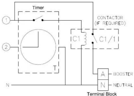
TIMER WITH CONTACTOR (if required)
A multiple installation of Rheem thermosiphon solar water heaters on a single manifold or multiple manifolds is possible, using the Rheem Equa-Flow ^® manifold system, where large volumes of hot water are required. It is recommended the electrical heating units of Rheem thermosiphon solar water heaters installed in a multiple installation, not be connected to a power supply. Rheem heavy duty water heaters should be installed in series with the solar water heaters to boost the water temperature during periods of poor or no solar gain.
An over temperature protection device should be fitted to each thermosiphon water heater when used as a preheater to an inline booster water heater.
The cold water and hot water manifolds must be designed to balance the flow from each solar storage tank. To achieve this, there are basic installation requirements and principles which must be followed:
- The maximum number of solar storage tanks in a bank should be 8, however several banks of solar storage tanks can be installed.
- The hot water line from the manifold must leave from the opposite end to which the cold water line enters the manifold.
- The solar storage tanks must be of the same model.
- The cold water line, cold and hot water headers and hot water line must be sized to meet the requirements of both AS/NZS 3500.4 and the application.
- A non return valve, isolation valve and if required a pressure limiting valve and expansion control valve, must be installed on the cold water line to the system.
- A full flow gate valve or ball valve (not stop taps, as used on a single solar storage tank installation) must be installed on both the cold water branch and hot water branch of each solar storage tank.
- Non return valves or pressure limiting valves must not be installed on the branch lines to the solar storage tanks.
- All fittings, valves and branch lines must be matched sets all the way along the manifold.
- Sufficient space must be left to enable access, servicing or removal of each solar storage tank.
- The temperature pressure relief valve drain line from each solar storage tank can terminate at a common tundish (funnel) with a visible air break at each drain discharge point (refer to the diagram on page 58 and to "Relief Drain Line" on page 53).
Refer to the diagram on page 58 for installation and plant layout details.
RHEEM COMMERCIAL SOLAR THERMOSIPHON - DOUBLE ARRAY
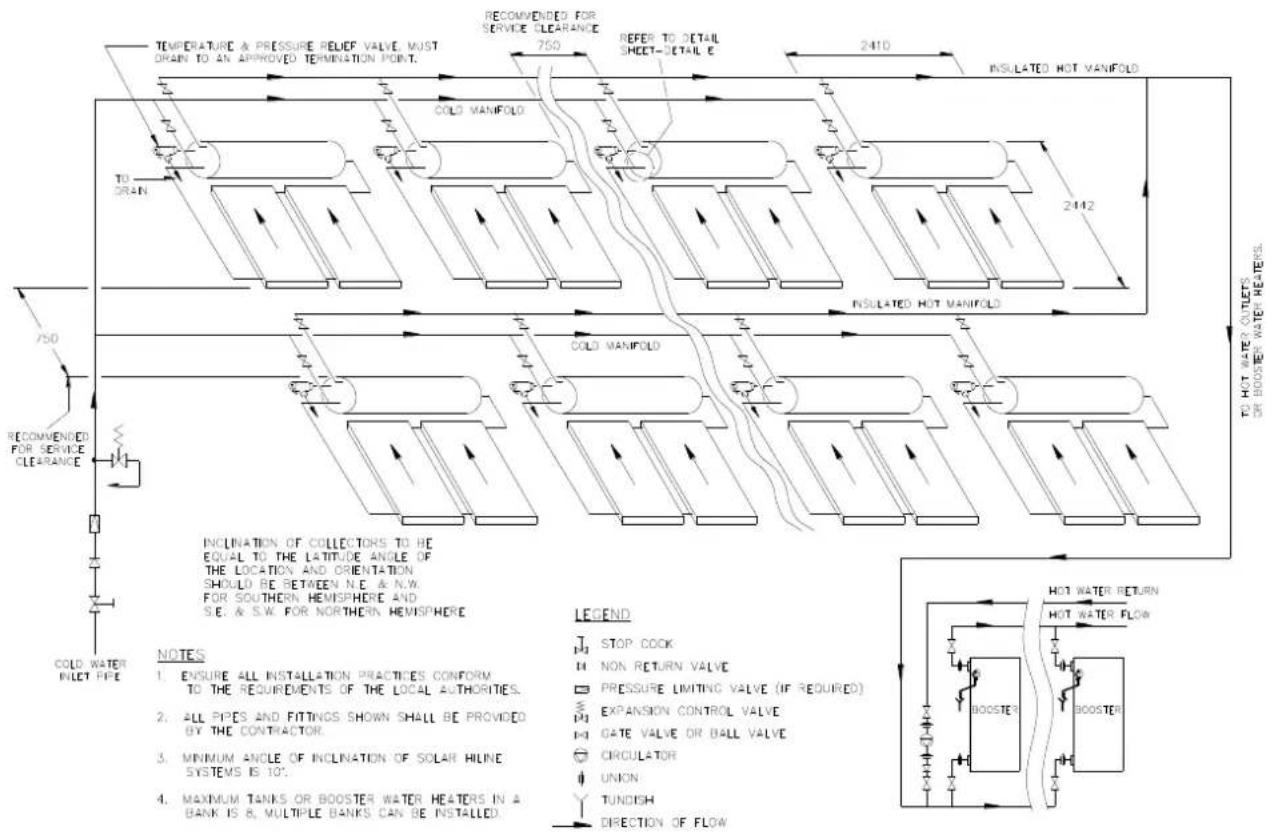
FIX ALL PIPES SECURELY IN POSITION CENTRALLY OVER TUNDISH

TO FINAL DISCHARGE OUTSIDE BUILDING IN ACCORDANCE WITH REQUIREMENTS OF LOCAL AUTHORITIES.
TPR Valve Drain Line
Common Discharge Point
TO FILL AND TURN ON THE WATER HEATER
The power supply to the solar storage tank must not be switched on until the water heater is filled with water and a satisfactory megger reading is obtained.
- Open all of the hot water taps in the house (don't forget the shower).
- Open the isolation valves fully on the cold and hot water branches to the water heater(s) in a bank.
- Open the cold water isolation valve fully on the cold water line to the water heater(s).
Air will be forced out of the taps.
- Close each tap as water flows freely from it.
- Check the pipe work for leaks.
- If an indirect system, fill the closed circuit heat exchanger and solar collectors with the closed circuit fluid. Refer to “Closed Circuit Fluid” on page 60.
- Switch on the electrical supply at the isolating switch to the solar storage tank(s).
- Set the timer if one is installed (refer to "Booster Control" on page 55).
Explain to the householder or a responsible officer the functions and operation of the water heater and the timer if one is installed. Upon completion of the installation and commissioning of the water heater, leave this guide with the householder or responsible officer.
INSTALLATION CHECKLIST
Prior to handover, complete the final check list:
- Air bled from taps ....[ ]
- System checked for water (and glycol) leaks....[ ]
- Cold and hot water piping checked for water leaks......[ ]
- Roof tiles put back into position......[ ]
- Roof flashing watertight....[ ]
- Collectors have correct kick (12-15 mm per collector)....[ ]
- Drain pipes free of any obstruction......[ ]
- All pipe work clipped where necessary ....[ ]
- Operation of booster checked ....[ ]
- Protective plastic film removed from tank and collectors (if fitted) ....[ ]
- Owner instructed on use ....[ ]
TO TURN OFF THE WATER HEATER
If it is necessary to turn off the water heater on completion of the installation, such as on a building site or where the premises is vacant, then:
- Switch off the electrical supply at the isolating switch to the solar storage tank(s).
- Close the cold water isolation valve at the inlet to the water heater(s) to shut down the entire system, or;
- Close the isolation valves on the cold and hot water branches to shut down an individual water heater in a bank.
CLOSED CIRCUIT FLUID
Important: It is recommended the solar storage tank be filled with water before charging the solar heat exchanger with the closed circuit fluid.
The closed circuit concentrate is supplied in 1.5 litre bottles. Mix the required quantity of closed circuit concentrate with the correct quantity of water to achieve the correct closed circuit fluid for the system. Failure to mix the closed circuit fluid correctly may void the Rheem warranty.
| System | Closed Circuit Concentrate Requirement for Minimum Operating Temperature | Mixed Total | |
| -8°C | -28°C | ||
| 52H180 (1 collector) | 1 x 1.5 litre bottle | 2 x 1.5 litre bottles | 4 litres |
| 52H300 (2 collectors) | 1 x 1.5 litre bottle | 2 x 1.5 litre bottles | 7 litres |
| 52H300 (3 collectors) | 2 x 1.5 litre bottle | 3 x 1.5 litre bottles | 9 litres |
Caution: Although the closed circuit concentrate is of food grade and non toxic, care must be taken not to accidentally consume or spill any of the closed circuit concentrate when handling. Only use approved closed circuit concentrate. If required, a Material Safety Data Sheet can be sought from Rheem.
While the closed circuit fluid is non toxic to humans, it does have an adverse effect on water stored in rainwater tanks. It can cause an unpleasant odour to develop, render the rainwater foul and unfit for human consumption and result in the rain water tank having to be drained and cleaned. Refer to “Rain Water Tank” on page 22.
⚠ Warning: Although non-toxic, the following first aid advice and procedures should be followed if the closed circuit concentrate comes into human contact or is spilt:
- Swallowed - give milk or water and seek medical attention.
- Eyes – flush with flowing lukewarm water.
- Skin - remove contaminated clothing and wash skin with water and soap.
- Inhaled - seek fresh air, rest and keep warm.
- Spilt - immediately remove contaminated clothing, stop leak source, absorb with a dry agent and eliminate any ignition sources nearby.
To Fill The Closed Circuit
It is necessary to fill the heat exchanger and solar collectors with closed circuit fluid before the water heater can be operated. Refer to diagram on page 61.
Note: Care must be taken to ensure there is no spillage of the closed circuit fluid onto the roof surface, particularly if the roof is part of a rain water collection system. Any spilled closed circuit fluid must be cleaned up immediately and the roof surface cleaned of any fluid residue.
To fill the heat exchanger:
-
Remove the retaining clip and 200 kPa pressure relief valve from the tank vent socket located on the right hand end of the solar storage tank.
This is the fill level for the closed circuit fluid and will allow air to escape during filling. -
Open the Service Valve (used on collectors with screw fittings) or remove the screw from the Fill Plug Assembly (used on collectors with conetite fittings) located at the bottom right hand corner of the right hand solar collector.
- Connect a hose to the Service Valve or Fill Plug Assembly.
- Using a funnel placed in the end of the hose, pour water into the system through the funnel until water flows from the vent socket. Note: the funnel must be held at a level that is above the vent socket.
- Close the Service Valve or remove the hose and refit the screw into the Fill Plug Assembly.
- Insert the 200 kPa pressure relief valve into the vent socket and secure with the retaining clip.
- Pressurise the closed circuit system up to 170 kPa and leave for ten minutes.
- Check the system for leaks at all connections.
• If no leaks are evident:
■ remove the retaining clip and 200 kPa pressure relief valve,
- open the Service Valve or remove the screw from the Fill Plug Assembly and reconnect the hose,
- using a funnel placed in the end of the hose, pour the required contents of the closed circuit fluid into the system through the funnel,
Water will be displaced through the vent socket as the closed circuit concentrate is added.
- add a further 500 ml of water to flush the closed circuit concentrate through the hose and into the collector.
- Close the Service Valve or remove the hose and refit the screw into the Fill Plug Assembly.
- Insert the 200 kPa pressure relief valve into the vent socket and secure with the retaining clip.
- Pressurise the closed circuit system up to 170 kPa and leave for ten minutes.
- Check the system for leaks at all connections.
- When satisfied there are no leaks present, remove the hose from the Service Valve.
Clean up any spilt closed circuit fluid.
Note: The closed circuit fluid level should be checked every five (5) years or at each major service and if required topped up or replaced.
The closed circuit fluid contains food grade additives (rust inhibitor, anti-freeze agent, colour) and is harmless to the environment. However, it is good practice to recover any excess closed circuit fluid and remove from site.

Filling The Closed Circuit With Closed Circuit Fluid
To drain the solar storage tank:
- Cover the solar collectors to prevent solar radiation gain and the transfer of heat to the solar storage tank.
Failure to do so may cause a safety issue. - Open a hot water tap and allow the water to run for five minutes immediately prior to draining the solar storage tank.
This will assist in the transfer of any heat from high temperature closed circuit fluid in the solar collectors to the water in the solar storage tank. - Close the hot water tap.
⚠ Warning: Exercise care to avoid splashing of water, as water discharged from the solar storage tank may be of a very high temperature.
Note: The water discharged from the solar storage tank may contain sediments and should be diverted away from any rainwater tank connected to the roof.
- Turn off the water heater (refer to "To Turn Off the Water Heater" on page 59).
- Close all hot water taps.
- 52H / RLX Series – Operate the closed circuit pressure relief valve on the right side of the solar storage tank to relieve the pressure from the closed circuit.
⚠ Warning: Relieved air or closed circuit fluid may be hot.
- Operate the temperature pressure relief valve release lever on the left hand side of the solar storage tank - do not let the lever snap back or you will damage the valve seat.
Operating the lever will release the pressure in the solar storage tank.
- 52H / RLX Series – Undo the union at the cold water inlet to the solar storage tank and attach a hose.
52L / RL Series – Undo the union at the cold water inlet connection on the shoulder of the solar cold pipe and attach a hose.
If it is necessary to drain the solar collectors, unscrew and remove the end plugs from the bottom right and top left ends of the solar collectors.
Let the other end of the hose go to a drain.
- Operate the relief valve again.
This will let air into the solar storage tank and allow the water to drain through the hose.
DRAINING THE CLOSED CIRCUIT - 52H / RLX SERIES
It is recommended to drain the solar collectors and heat exchanger every five years. The closed circuit fluid should be checked and if necessary replaced. Draining the solar collectors and closed circuit should be conducted within three hours of sunrise, when the closed circuit fluid temperature inside the solar collectors is lower.
To drain the solar collectors and closed circuit:
- Cover the solar collectors to prevent solar radiation gain.
Failure to do so may cause a safety issue.
- Open a hot water tap and allow the water to run for five minutes immediately prior to draining the solar storage tank.
This will assist in the transfer of any heat from high temperature closed circuit fluid in the solar collectors to the water in the solar storage tank.
- Close the hot water tap.
⚠ Warning: Exercise care to avoid splashing of closed circuit fluid, as fluid discharged from the solar collectors may be of a very high temperature.
Note: The closed circuit fluid discharged from the solar collectors can render the water in a rain water tank unusable and should be diverted away from any rainwater tank connected to the roof.
- Operate the closed circuit pressure relief valve on the right side of the solar storage tank to relieve the pressure from the closed circuit.
⚠ Warning: Relieved air or closed circuit fluid may be hot.
- System with Fill Plug Assembly: Remove the screw from the Fill Plug Assembly (used on collectors with conetite fittings) and attach a hose to the assembly.
Place the end of the hose into a container.
- System with Service Valve: Attach a hose to the spigot and open the Service Valve (used on collectors with screwed fittings).
Place the end of the hose into a container.
- Remove the retaining clip and the closed circuit pressure relief valve from the tank vent socket.
- Allow the closed circuit fluid to drain into a container and dispose of in accordance with the relevant local authority.
⚠ Warning: Closed circuit fluid may be hot.
To fill the solar collectors, refer to "To Fill The Closed Circuit" on page 60.
It may be necessary to flush the storage tank (52H or 52L tank) and solar collectors (52L) if there is sediment in the water supply. This should be conducted in the morning, within three hours of sunrise, when the water or closed circuit fluid temperature inside the solar collectors is lower.
- Cover the solar collectors to prevent solar radiation gain and the transfer of heat to the solar storage tank.
Failure to do so may cause a safety issue. - Open a hot water tap and allow the water to run for five minutes immediately prior to flushing or draining the solar storage tank and / or solar collectors.
This will assist in the transfer of any heat from high temperature water or closed circuit fluid in the solar collectors to the water in the solar storage tank. - Close the hot water tap.
⚠ Warning: Exercise care to avoid splashing of water, as water discharged from the solar storage tank and solar collectors may be of a very high temperature.
Note: The water discharged from the water heater may contain sediments and should be diverted away from any rainwater tank connected to the roof.
To flush the storage tank (52H or 52L tank) and solar collectors (52L):
- Turn off the water heater (refer to "To Turn Off The Water Heater" on page 59).
- 52H / RLX series – Operate the closed circuit pressure relief valve on the right side of the solar storage tank to relieve the pressure from the closed circuit.
⚠ Warning: Relieved air or closed circuit fluid may be hot. - Operate the relief valve lever – do not let the lever snap back or you will damage the valve seat.
Operating the lever will release the pressure in the water heater. - 52L / RL series – From the bottom right and top left ends of the solar collectors, unscrew and remove the end plugs.
- 52H / RLX series – Undo the union at the cold water inlet to the solar storage tank and attach a hose.
- Flush and hose inside tank:
- disconnect and remove the booster heating unit,
- Place a hose inside the tank,
- Open the isolation valve to the hose,
- Allow hose to run until water runs clear from the solar collectors (52L) or from the hose connected to the cold water connection (52H),
- Close the isolation valve to the hose and remove the hose from the tank,
- Replace and reconnect the booster heating unit,
- 52H / RLX series – Disconnect the hose from the cold water inlet and reconnect the cold water pipe work.
- 52L / RL series – Open the cold water isolation valve to the water heater.
- Allow water to flow from the solar collectors until it is clear of any sediment.
- When satisfied the solar storage tank and solar collectors are flushed, close the cold water isolation valve to the water heater and reconnect all fittings to their original location.
- Open the cold water isolation valve to the water heater fully, check fittings for leaks and switch on the power.
It is recommended to flush the solar storage tank and solar collectors every five years. This will assist in keeping the solar collectors, solar cold pipe and solar hot pipe clear of sediment.
This page is intentionally blank.
RHEEM SOLAR THERMOSIPHON WATER HEATER WARRANTY – AUSTRALIA ONLY
SOLAR THERMOSIPHON WATER HEATER SYSTEMS - 52L, 52H, RL, RLX
1. THE RHEEM WARRANTY - GENERAL
1.1 This warranty is given by Rheem Australia Pty Limited ABN 21 098 823 511 of 1 Alan Street, Rydalmere New South Wales.
1.2 Rheem offer a trained and qualified national service network who will repair or replace components at the address of the water heater subject to the terms of the Rheem warranty. Rheem Service, in addition can provide preventative maintenance and advice on the operation of your water heater. The Rheem Service contact number is available 7 days a week on 131031 with Service personnel available to take your call from 8am to 8pm daily (hours subject to change).
1.3 For details about this warranty, you can contact us on 131031 or by email at warrantyenquiry@rheem.com.au (not for service bookings).
1.4 The terms of this warranty and what is covered by it are set out in sections 2 and 3 and apply to water heaters manufactured after 1st September 2014.
1.5 If a subsequent version of this warranty is published, the terms of that warranty and what is covered by it will apply to water heaters manufactured after the date specified in the subsequent version.
2. TERMS OF THE RHEEM WARRANTY AND EXCLUSIONS TO IT
2.1 The decision of whether to repair or replace a faulty component is at Rheem's sole discretion.
2.2 If you require a call out and we find that the fault is not covered by the Rheem warranty, you are responsible for our standard call out charge. If you wish to have the relevant component repaired or replaced by Rheem, that service will be at your cost.
2.3 Where a failed component or cylinder is replaced under this warranty, the balance of the original warranty period will remain effective. The replacement does not carry a new Rheem warranty.
2.4 Where the water heater is installed outside the boundaries of a metropolitan area as defined by Rheem or further than 25 km from either a regional Rheem branch office or an Accredited Rheem Service Agent's office, the cost of transport, insurance and travelling between the nearest branch office or Rheem Accredited Service Agent's office and the installed site shall be the owner's responsibility.
2.5 Where the water heater is installed in a position that does not allow safe or ready access, the cost of that access, including the cost of additional materials handling and/or safety equipment, shall be the owner's responsibility. In other words, the cost of dismantling or removing cupboards, doors or walls and the cost of any special equipment to bring the water heater to floor or ground level or to a serviceable position is not covered by this warranty.
2.6 This warranty only applies to the original and genuine Rheem water heater in its original installed location and any genuine Rheem replacement parts.
2.7 The Rheem warranty does not cover faults that are a result of:
a) Accidental damage to the water heater or any component (for example: (i) Acts of God such as floods, storms, fires, lightning strikes and the like; and (ii) third party acts or omissions).
b) Misuse or abnormal use of the water heater.
c) Installation not in accordance with the Owner's Guide and Installation Instructions or with relevant statutory and local requirements in the State or Territory in which the water heater is installed.
d) Connection at any time to a water supply that does not comply with the water supply guidelines as outlined in the Owner's Guide and Installation Instructions.
e) Repairs, attempts to repair or modifications to the water heater by a person other than Rheem Service or a Rheem Accredited Service Agent.
f) Faulty plumbing or faulty power supply.
g) Failure to maintain the water heater in accordance with the Owner's Guide and Installation Instructions.
h) Transport damage.
i) Fair wear and tear from adverse conditions (for example, corrosion).
j) Cosmetic defects.
k) Breakage of collector glass for any reason including hail damage (we suggest that the collector glass be covered by your home insurance policy).
I) Ice formation in the waterways of a: direct open circuit thermosiphon system; or an indirect closed circuit thermosiphon system due to non Rheem approved or incorrectly mixed closed circuit fluid being used.
m) Non Rheem approved or incorrectly mixed closed circuit fluid being used or incorrect or insufficient filling of the closed circuit system with the closed circuit fluid.
2.8 Subject to any statutory provisions to the contrary, this warranty excludes any and all claims for damage to furniture, carpet, walls, foundations or any other consequential loss either directly or indirectly due to leakage from the water heater, or due to leakage from fittings and/or pipe work of metal, plastic or other materials caused by water temperature, workmanship or other modes of failure.
2.9 If the water heater is not sized to supply the hot water demand in accordance with the guidelines in the Rheem water heater literature, any resultant fault will not be covered by the Rheem warranty.
RHEEM SOLAR THERMOSIPHON WATER HEATER WARRANTY – AUSTRALIA ONLY
SOLAR THERMOSIPHON WATER HEATER SYSTEMS - 52L, 52H, RL, RLX
3. WHAT IS COVERED BY THE RHEEM WARRANTY FOR THE WATER HEATERS DETAILED IN THIS DOCUMENT
3.1 Rheem will repair or replace a faulty component of your water heater if it fails to operate in accordance with its specifications as follows:
| What components are covered | The period from the date of installation in which the fault must appear in order to be covered | What coverage you receive |
All Systems (all installations)
| All components | Year 1 | Repair and/or replacement of the faulty component, free of charge, including labour. |
52L, 52H Series Systems
| The cylinder(if the water heater is installed in a single-family domestic dwelling) | Years 2 to 7 | Replacement cylinder, free of charge. Installation and repair labour costs are the responsibility of the owner. |
| The cylinder(if the water heater is not installed in a single-family domestic dwelling) | Years 2 & 3 | Replacement cylinder, free of charge. Installation and repair labour costs are the responsibility of the owner. |
| The solar collector(all installations) | Years 2 to 5 | Replacement solar collector, free of charge. Installation and repair labour costs are the responsibility of the owner. |
RL, RLX Australis Series Systems (if the water heater is installed in a single-family domestic dwelling)
| The cylinder and solar collector(s) | Years 2 & 3 | Replacement cylinder or solar collector, free of charge, including labour. |
| Years 4 to 7 | Replacement cylinder or solar collector, free of charge. Installation and repair labour costs are the responsibility of the owner. |
RL, RLX Australis 10 & Titan Series Systems (if the water heater is installed in a single-family domestic dwelling)
| All components | Year 2 to 5 | Repair and/or replacement of the faulty component, free of charge, including labour. |
| The cylinder and solar collector(s) | Years 6 to 10 | Replacement cylinder or solar collector, free of charge. Installation and repair labour costs are the responsibility of the owner. |
RL, RLX Australis, Australis 10 & Titan Series Systems (if the water heater is not installed in a single-family domestic dwelling)
| The cylinder and solar collector(s) | Years 2 & 3 | Replacement cylinder or solar collector, free of charge. Installation and repair labour costs are the responsibility of the owner. |
| Year 4 | Replacement cylinder or solar collector, supplied at 75% of list price. Installation and repair labour costs and 25% of cylinder or solar collector list price are the responsibility of the owner. | |
| Year 5 | Replacement cylinder or solar collector, supplied at 50% of list price. Installation and repair labour costs and 50% of cylinder or solar collector list price are the responsibility of the owner. |
RHEEM SOLAR THERMOSIPHON WATER HEATER WARRANTY – AUSTRALIA ONLY
SOLAR THERMOSIPHON WATER HEATER SYSTEMS - 52L, 52H, RL, RLX
4. ENTITLEMENT TO MAKE A CLAIM UNDER THIS WARRANTY
4.1 To be entitled to make a claim under this warranty you need to:
a) Be the owner of the water heater or have consent of the owner to act on their behalf.
b) Contact Rheem Service without undue delay after detection of the defect and, in any event, within the applicable warranty period.
4.2 You are not entitled to make a claim under this warranty if your water heater:
a) Does not have its original serial numbers or rating labels.
b) Is not installed in Australia.
5. HOW TO MAKE A CLAIM UNDER THIS WARRANTY
5.1 If you wish to make a claim under this warranty, you need to:
a) Contact Rheem on 131031 and provide owner's details, address of the water heater, a contact number and date of installation of the water heater or if that's unavailable, the date of manufacture and serial number (from the rating label on the water heater).
b) Rheem will arrange for the water heater to be tested and assessed on-site.
c) If Rheem determines that you have a valid warranty claim, Rheem will repair or replace the water heater in accordance with this warranty.
5.2 Any expenses incurred in the making of a claim under this warranty will be borne by you.
6. THE AUSTRALIAN CONSUMER LAW
6.1 Our goods come with guarantees that cannot be excluded under the Australian Consumer Law. You are entitled to a replacement or refund for a major failure and for compensation for any other reasonably foreseeable loss or damage. You are also entitled to have the goods repaired or replaced if the goods fail to be of acceptable quality and the failure does not amount to a major failure.
6.2 The Rheem warranty (set out above) is in addition to any rights and remedies that you may have under the Australian Consumer Law.
RHEEM AUSTRALIA PTY LTD, A.B.N. 21 098 823 511, www.rheem.com.au
For Service Telephone 131 031 AUSTRALIA or 0800 657 335 NEW ZEALAND

- Installation Instructions
- Solar Thermosiphon Water Heater
- Stainless Steel Tanks
- WARNING: Plumber – Be Aware
- PATENTS
- TRADE MARKS
- CONTENTS
- WATER HEATER APPLICATION
- MODEL TYPE
- SOLAR OPERATION
- ELECTRIC BOOSTING
- MAINS PRESSURE
- HOTTER WATER INCREASES THE RISK OF SCALD INJURY
- TEMPERATURE ADJUSTMENT
- WARNING
- SAFETY
- PRECAUTIONS
- BOOSTER CONTROL
- Timer Control Switch
- Programming the Timer
- RAIN WATER TANK
- FREEZE PROTECTION
- PIPE WORK AND INSULATION
- TO TURN OFF THE WATER HEATER
- TO TURN ON THE WATER HEATER
- GOING ON HOLIDAYS
- HOW DO I KNOW IF THE WATER HEATER IS INSTALLED CORRECTLY?
- VICTORIAN CUSTOMERS
- DOES THE WATER CHEMISTRY AFFECT THE WATER HEATER?
- HOW LONG WILL THE WATER HEATER LAST?
- MINOR SIX MONTH MAINTENANCE
- MAJOR FIVE YEAR SERVICE
- TEMPERATURE PRESSURE RELIEF VALVE
- EXPANSION CONTROL VALVE
- COLLECTOR GLASS
- CHANGE OF WATER SUPPLY
- CHLORIDE AND PH
- SATURATION INDEX
- SUMMARY OF WATER CHEMISTRY ADVICE AFFECTING WARRANTY
- Water Chemistry
- Component
- NOT ENOUGH HOT WATER (OR NO HOT WATER)
- - Insufficient sunlight
- - Booster heating unit not operating
- - Collectors shaded
- - Are you using more hot water than you think?
- • Temperature pressure relief valve running
- • Thermostat setting
- • Water heater size
- WATER NOT HOT ENOUGH
- TEMPERATURE PRESSURE RELIEF VALVE RUNNING
- - Normal Operation
- • Continuous dribble
- • Steady flows for long period (often at night)
- - Heavy flows of hot water until the water heater is cold - then stops until water reheats
- EXPANSION CONTROL VALVE RUNNING
- HIGHER THAN EXPECTED ELECTRICITY BILLS
- ELECTRICITY TARIFFS
- THIS WATER HEATER IS NOT SUITABLE FOR POOL HEATING.
- SOLAR COLLECTORS
- IMPORTANT NOTES
- INSTALLATION STANDARDS
- Victorian Installers
- SOLAR WATER HEATER STORAGE TANK LOCATION
- SAFE TRAY
- MAINS WATER SUPPLY
- TANK WATER SUPPLY
- HOT WATER DELIVERY
- CIRCULATED HOT WATER FLOW AND RETURN SYSTEM
- Temperature Limiting Device
- REDUCING HEAT LOSSES
- SADDLING - PIPE WORK
- BOOSTER HEATING UNIT
- PLASTIC END COVER
- TANK REPLACEMENT
- COLLECTOR REPLACEMENT
- OVER-TEMPERATURE PROTECTION
- RL System Over-Temperature Protection
- RLX System Over-Temperature Protection
- ASSEMBLY DIAGRAM - 52H SERIES WITHOUT OTP - CONETITE FITTING COLLECTORS
- Components
- ASSEMBLY DIAGRAM - 52L, RL SERIES WITHOUT TRV - SCREWED FITTING COLLECTORS
- ASSEMBLY DIAGRAM - 52L, RL SERIES WITH TRV - SCREWED FITTING COLLECTORS
- ASSEMBLY DIAGRAM – RLX SERIES WITHOUT OTP – SCREWED FITTING COLLECTORS
- ASSEMBLY DIAGRAM – RLX SERIES WITH OTP – SCREWED FITTING COLLECTORS
- ROOF STRENGTH
- ORIENTATION OF SOLAR COLLECTORS
- INCLINATION OF SOLAR COLLECTORS
- CYCLONIC OR HIGH WIND AREAS
- SYSTEM ASSEMBLY
- COMPONENTS AND KIT CONTENTS
- DO NOT MODIFY THESE PARTS IN ANY WAY.
- Notes:
- Collector Mounting Rail Preparation
- Noting the orientation of the collector strap's folded end:
- Collector Mounting Rail Installation:
- NOTE ON SCREWED FITTING CONNECTIONS
- Tank to Collector Spacers and Solar Storage Tank:
- Tank to Collector Connections of Pipe Work:
- Fill Plug (Indirect System Only):
- Collector Bung / End Plugs:
- Asbestos Roofs
- Pitch roofs - Greater than 30°
- INSTALLATION CHECK LIST
- WATER INLET AND OUTLET
- PIPE SIZES
- IN-SERIES BOOSTER (IF INSTALLED)
- RELIEF VALVE DRAIN
- SOLAR STORAGE TANK
- THERMOSTAT SETTING
- TO FILL AND TURN ON THE WATER HEATER
- INSTALLATION CHECKLIST
- CLOSED CIRCUIT FLUID
- To Fill The Closed Circuit
- DRAINING THE CLOSED CIRCUIT - 52H / RLX SERIES
- RHEEM SOLAR THERMOSIPHON WATER HEATER WARRANTY – AUSTRALIA ONLY
- SOLAR THERMOSIPHON WATER HEATER SYSTEMS - 52L, 52H, RL, RLX
- THE RHEEM WARRANTY - GENERAL
- TERMS OF THE RHEEM WARRANTY AND EXCLUSIONS TO IT
- WHAT IS COVERED BY THE RHEEM WARRANTY FOR THE WATER HEATERS DETAILED IN THIS DOCUMENT
- ENTITLEMENT TO MAKE A CLAIM UNDER THIS WARRANTY
- HOW TO MAKE A CLAIM UNDER THIS WARRANTY
- THE AUSTRALIAN CONSUMER LAW
Brand : Rheem
Model : 591270
Category : Heating