
QFlex 48-WP - Loudspeaker TANNOY - Free user manual and instructions
Find the device manual for free QFlex 48-WP TANNOY in PDF.


| Product Type | Weatherproof Passive Column Loudspeaker |
| Brand | Tannoy |
| Model | QFlex 48-WP |
| Driver Configuration | 8 x 4.0" (100 mm) full-range drivers |
| Frequency Response (-10 dB) | 80 Hz – 20 kHz |
| Power Handling (Continuous) | 150 W |
| Power Handling (Peak) | 600 W |
| Impedance (Nominal) | 16 Ω |
| Sensitivity (1 W / 1 m) | 90 dB SPL |
| Maximum SPL (Peak) | 118 dB |
| Coverage (Horizontal) | 120° (constant directivity) |
| Coverage (Vertical) | Array-dependent, typically 20° – 30° |
| Enclosure Material | Extruded aluminum, weatherized |
| Weatherproof Rating | IP54 (splash and dust resistant) |
| Dimensions (H x W x D) | 96.5 x 15.0 x 19.5 cm (38.0 x 5.9 x 7.7 in) |
| Weight | 5.4 kg (11.9 lb) |
| Connection Type | Screw terminal block |
| Mounting | Wall mount bracket included (multi-angle) |
| Application | Foreground music, paging, voice alarm |
| Maintenance & Cleaning | Wipe with a soft damp cloth; do not use solvents or abrasive cleaners |
| Safety | Installation by qualified personnel only. Adhere to local electrical and safety codes. |
| Spare Parts & Repairability | Serviceable with standard tools; replacement drivers and grilles available through authorized distributors |
Frequently Asked Questions - QFlex 48-WP TANNOY
User questions about QFlex 48-WP TANNOY
0 question about this device. Answer the ones you know or ask your own.
Ask a new question about this device
Download the instructions for your Loudspeaker in PDF format for free! Find your manual QFlex 48-WP - TANNOY and take your electronic device back in hand. On this page are published all the documents necessary for the use of your device. QFlex 48-WP by TANNOY.
USER MANUAL QFlex 48-WP TANNOY
No user serviceable parts inside, refer servicing to qualified personnel

CAUTION
RISK OF ELECTRIC SHOCK DO NOT OPEN
ATTENTION
RISQUE DE CHOC ELECTRIQUE NE PAS ENLEVER

DO NOT EXPOSE TO RAIN OR MOISTURE
NE PAS EXPOSER A LA PLUIE NI A L'HUMIDITE

CET EQUIPEMENT DOIT ETRE RELIE A LA TERRE
This equipment is designed for permanent installation. Disconnection from the mains supply is to be achieved by isolation of the circuit to which it is connected.
Do not remove any covers, loosen any fixings or allow items to enter any aperture.
Objects filled with liquids should not be placed on this apparatus.
The rear of this product can get hot. Avoid direct skin contact during operation and for at least 5 minutes after power has been isolated.
To prevent injury this apparatus must be secured to the wall in accordance with the installation instructions.
AVERTISSEMENT DE SECURITE
IMPORTANT SAFETY INSTRUCTIONS
1 Read these instructions.
2 Keep these instructions.
3 Heed all warnings.
4 Follow all instructions.
5 Do not use this apparatus near water.
6 Clean only with dry cloth.
7 Do not block any ventilation openings. Install in accordance with the manufacturer's instructions.
8 Do not install near any heat sources such as radiators, heat registers, stoves or other apparatus (including amplifiers) that produce heat.
9 Only use attachments / accessories specified by the manufacturer.
10 Refer all servicing to qualified service personnel. Service is required when the apparatus has been damaged in any way, such as, liquid has been spilled or objects have fallen into the apparatus, this apparatus has been exposed to rain or moisture, does not operate normally, or has been dropped.
INSTALLATION INSTRUCTIONS
1 THIS PRODUCT MUST BE EARTHED. The safety ground terminal of the appliance must be connected to the earthing terminal of the installation. The cord must be of maximum length 7.5 meters, rated SJ, SJT, or SJE, 10A minimum and be marked VW-1.
2 The electrical power connection to this product is only to be made via the connector as supplied with the equipment and available from Tannoy under part number 3431-1150.
3 Wiring to this connector must conform with instructions in this manual, must only be made by suitably qualified personnel and must comply with all local requirements.
4 Do not install this equipment in an enclosed space. Do not limit free ventilation and movement of air around the back panel. Ensure that there is at least 100mm (4") of space around all sides of the product for ventilation.
5 QFlex modules must only be joined or separated with the complete column laying flat on the ground and disconnected from the mains supply.
6 QFlex is designed and intended for use in non-domestic situations. Mains power is to be supplied from a permanent hard wired feed. The feed for each QFlex must be protected by a fuse or circuit breaker rated at no more than 10A. It must be possible to isolate the feed to each QFlex by means of a double pole switch with a minimum of 3mm contact separation.
IMPORTANTES INSTRUCTIONS RELATIVES A LA SECURITE
This product complies with both the LVD (electrical safety) 73/23/EEC and EMC (electromagnetic compatibility) 89/336/EEC directives issues by the commission of the European community.
Compliance with these directives implies conformity with the following European standards:
EN60065 Product safety
EN55103-1 EMC emissions
EN55103-2 EMC immunity
This product is intended for the following electromagnetic environments: E2; E3 & E4. Environment E1 (domestic) is specifically excluded.
FOR CUSTOMERS IN THE USA & CANADA
This product has been tested for electrical safety and complies with:
UL60065 7th edition 2003
CA /CSA C22.2 No.60065-03
This equipment has been designed to comply with the limits for a Class A digital device, pursuant to part 15 of the FCC Rules. These limits are designed to provide reasonable protection against harmful interference when the equipment is operated in a commercial environment.
Industry Canada Class A emission compliance statement: This Class A digital apparatus complies with Canadian ICES-003.
1 INTRODUCTION
2 UNPACKING
3 SOFTWARE INSTALLATION & SETUP
3.1 BeamEngine Programme
3.2 MatLab Runtime Library MCR
3.3 QFlex BeamEngine Application
3.4 Updates
3.5 Uninstalling
4 INSTALLING THE MATLAB RUNTIME LIBRARY
5 INSTALLING THE BEAMENGINE APPLICATION
6 USING BEAMENGINE
6.1 Menu
6.2 Laying Out Venue Planes
6.3 Optimize Results
6.4 Adding Additional Venue Items
6.5 Probes
6.6 Saving Steering File
6.7 Balloon Data
6.8 BeamEngine – Frequently asked Questions
6.9 Some Design Tips
7 INSTALLING VNET SOFTWARE (PODWARE)
8 USING VNET SOFTWARE (PODWARE)
8.1 Overview
8.2 Layout
8.3 Menus
8.4 Toolbar
8.5 Communications
8.6 Launching a Panel
8.7 Controlling Devices – a quick overview
8.8 Parameter Synchronisation
8.9 Progress Bar
8.8 Navigation
8.9 The Selected Device
8.10 Device Context Menu
8.11 Control Panels
8.12 Loading Steering Data
8.13 Monicons
8.14 Controls
8.15 Filter Response Panels
8.16 Off-Line Operation
8.17 Saving and Recalling Data
8.18 Loading Factory Settings
8.19 Cloning a Device
8.20 Operating Mode
8.21 Device Properties
8.22 Device Firmware
8.23 Keyboard shortcuts
9 HARDWARE CONFIGURATION (GENERAL INFORMATION)
10 ASSEMBLY INSTRUCTIONS
10.1 QFlex 8 & QFlex 16 Assembly
10.2 Wall Bracket Mounting Centres
- QFlex 8 & QFlex 16
10.3 QFlex 24 & QFlex 32 Assembly
10.4 Wall Bracket Mounting Centres
- QFlex 24 & QFlex 32
10.5 QFlex 40 Assembly
10.6 Wall Bracket Mounting Centres
- QFlex 40
10.7 QFlex 48 Assembly
10.8 Wall Bracket Mounting Centres
- QFlex 48
11 SYSTEM CONNECTIVITY
12 AUDIO CONNECTIONS
13 NETWORK CONNECTIONS
14 MAINS POWER
15 CONTROL INPUTS (SYSTEM INTEGRITY & EMERGENCY PROVISION)
16 INDICATORS
17 SERVICE PARTS
18 TECHNICAL SPECIFICATIONS
19 WARRANTY
1 INTRODUCTION
Congratulations on the purchase of your new QFlex loudspeaker.
QFlex is a range of self powered, digitally steerable loudspeaker arrays. With state of the art algorithms and dense physical spacing of transducers, QFlex is the first product of its kind to realize full range beam steering capabilities, producing class leading performance for both vocal and music applications. To avoid shipping very long products, it will be possible to assemble the components of a QFlex column on site.
QFlex products are small format, column-type loudspeaker systems with a user-variable vertical beamwidth pattern. The loudspeakers can be used singly or combined in multiples.
The simple to use BeamEngine software allows accurate adjustment of coverage area from a fixed, vertical mounting location. In addition to excellent vocal performance, the QFlex range fully capable of full-range music applications and can also be used in conjunction with any VNET ^™ subwoofer. Implementation of the network between nodes is via high quality rugged Neutrik Ethercon connectors, which are compatible with standard RJ45 plugs, and CAT5 cable. Each speaker has a unique address for auto-location on the network. System commissioning and ongoing venue network control, incorporating real time diagnostics of electronics and drive unit, are all managed by the exclusive VNET ^™ software package.
This manual provides information about the design, configuration, and operation of QFlex products. It is intended to be used in conjunction with the VNET ^™ & BeamEngine Windows software packages.
Please read this user manual to get the optimum performance from your QFlex loudspeaker system.
2 UNPACKING
Every Tannoy QFlex product is carefully tested and inspected before being packaged and leaving the factory. After unpacking your loudspeaker, please inspect for any exterior physical damage, and save the carton and any relevant packaging materials in case the loudspeaker again requires packing and shipping. In the event that damage has been sustained in transit notify your dealer immediately. Each QFlex carton is marked to show each modules position in the array. A detailed description can be found in the Hardware section of this manual.
3 SOFTWARE INSTALLATION & SETUP
QFlex loudspeakers are digitally controlled. A PC running BeamEngine and VNET software is needed during installation and the commissioning process.
The BeamEngine programme can be obtained by contacting QFlex info@tannoy.com
VNET software and BeamEngine are powerful applications capable of running many complex windows concurrently. They therefore require a computer with reasonable levels of resources.
For acceptable performance, the computer must have at least:
•PC with >450MHz Pentium processor
- 32-bit Windows tm operating system (2000, XP, Vista)
128MB RAM
500MB Disk space
•Screen with 1024 x 768 Pixel or better
CD-ROM drive or Internet access
•RS232 or USB port
However, for large systems, larger RAM will make a difference to speed. QFlex makes use of the MatLab Runtime Library MCR, which needs to be installed on your computer in order to run QFlex.
3.1 BEAMENGINE PROGRAMME
There are two programme modules to install. For both the installation is fully automatic. However, please note the following:-
Initialization time: Due to large data-files the installation may need a considerable time to load. Also, on the very first run of QFlex BeamEngine the MatLab Library needs to initialize, which cause a short delay.
Windows Vista: Do not install QFlex BeamEngine to the standard folder but elsewhere, for instance C:\Tannoy\QFlex.
Restricted User Rights: If you operate your computer under restricted user rights then it is best to install the \MatLab Library first and then to install QFlex BeamEngine. If you currently work with administrator rights on your PC the order of installation does not matter.
MatLab owners: If you have already installed MatLab or a MatLab Runtime Library on your computer, the modules should be of version 7.7. Otherwise install the provided package in parallel.
3.2 MATLAB RUNTIME LIBRARY MCR
The MatLab Runtime Library MCR needs to be installed separately. This MatLab Runtime Library is a special version (v7.7) and is exclusively provided to you by Tannoy.
- Log in as administrator, start the automatic installer by clicking on the link below and follow instructions.
- Use the default settings.
- Install MatLab Runtime Library v7.7
3.3 QFLEX BEAMENGINE APPLICATION
Install the QFlex BeamEngine module after the MatLab Library. The install is automatic. Under Vista it is recommended to install into another directory than the one suggested (say "C:\Tannoy\QFlex" for example).
- Log in as administrator, start the automatic installer by clicking on the link below and follow instructions.
- Install Tannoy QFlex
3.4 UNINSTALLING
Either go to Start Menu/Settings/Software or to the program-folder of QFlex, there double click unins000.exe
3.5 UPDATES
Install QFlex in the same location. The MatLab Library will not need to be reinstalled.
4 INSTALLING THE MATLAB RUNTIME LIBRARY
Having downloaded the software, double click on the MCRInstaller_v77.exe The following window will appear –
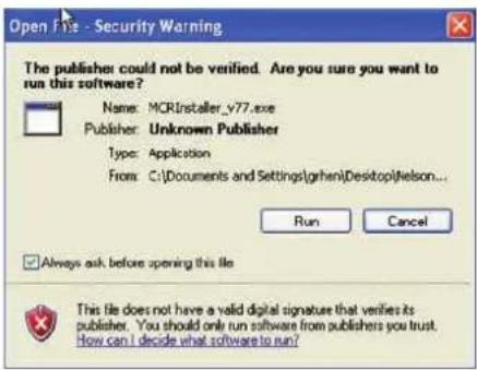
Click on "Run" to start the installer –
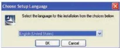
Choose the setup language and click 'Ok' to start the InstallShield wizard


The InstallShield window will appear – Click 'Next'

Enter your credentials and click 'Next'

Approve the suggested file location by clicking on 'Next'

Click on 'Install' to begin the Installation

The installation will begin. Due to the file size this may take some time
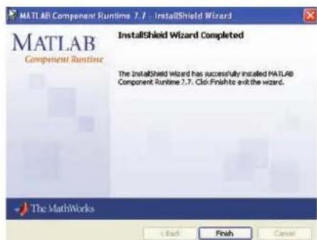
Click 'Finish' to complete the installation. There is no need to start this programme as it resides behind the BeamEngine programme. It will no longer be visible.
5 INSTALLING THE BEAMENGINE APPLICATION
Having downloaded the software, double click on the QFlex_vXXXX.exe The following window will appear.

The QFlex Setup wizard will start; click 'Next' to continue

Accept the terms of the licence agreement to continue with the installation. Click 'Next' to continue.
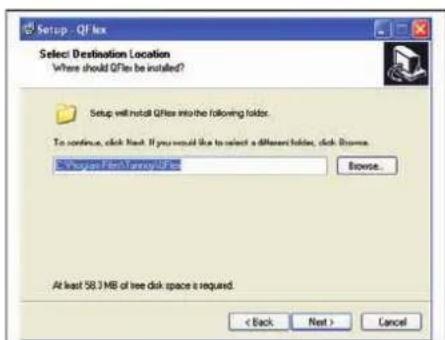
Approve the suggested file location by clicking on 'Next'
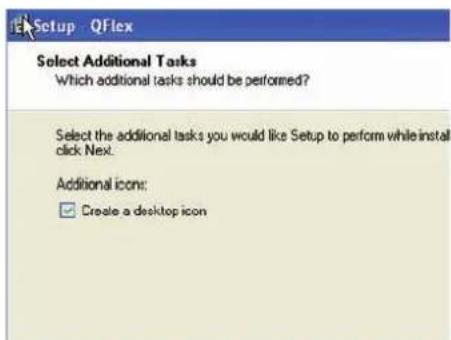
If you would like the setup programme to create a desktop icon check the box. Click 'Next' to continue.
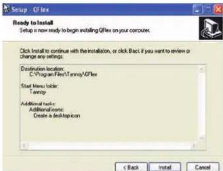

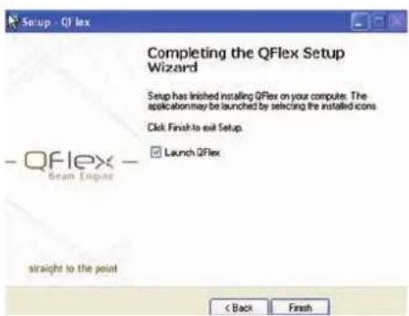
Check 'Launch QFlex' if you wish to begin using the software immediately.
Click 'Finish' to complete the setup.
6 USING BEAMENGINE
Click on the QFlex icon which the installer left on your desktop.
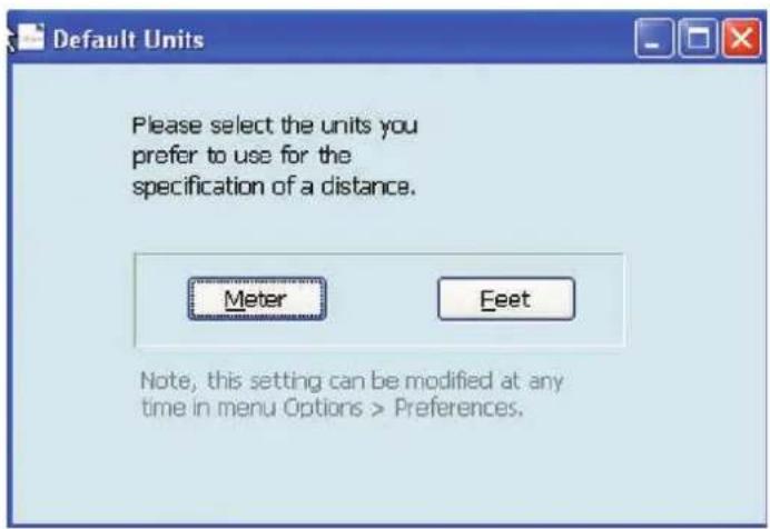
On the very first run of the program you will be prompted to select your preferred units of measurement. These settings can be modified at any time in the menu options.
The following shows the default screen –

6.1 MENU (File, Edit, Processing, Options, Help)
File
- From here you can create a new project, open an existing and save a project.
• A BeamEngine project has the file extension (.qfl) - Save a Beamsteering File (.bef)
- Save a 3D Balloon file (.xhn) for export into acoustical simulation programmes.
- Print a detailed project sheet. This includes Parameters, Project Notes & graphs.
- 'Export' generates a screenshot of your current project (.jpg)
Edit
- From here you select your QFlex Model (Keyboard shortcut – F8)
- Add menu item
- Delete menu item
Processing
- Optimize – Creates Beamsteering algorithm (Keyboard shortcut - CTRL + Enter)
- Update Graphs – Regenerates graphics (Keyboard shortcut – SHIFT, CTRL + Enter)
Options
Preferences
Optimizer Tab

Default Property
- Silent and Don't Care is explained in the menu.
The Master Beta function
Master multiplication factor to apply to regularization factors beta given in global A.wf(woofer) and A.tw(tweeter). Normally Masterbeta = 1, but it can be reduced to 0.1, trading some SPL for sharper directivity at the lower end of each sub-array's (tweeter or woofer) working range. It is recommended to use the default setting except in exceptional circumstances
Fill Holes
With multiple primary venue items (multi-beam problems) performance can be improved by setting Fill Holes = 1 (instead of 0). Then the narrow gaps in the target directivity are filled up at low frequencies where they can't be implemented anyway. In some cases this produces better results than asking for the impossible. The results are marginal, so no need to spend too much time here.
Units Tab
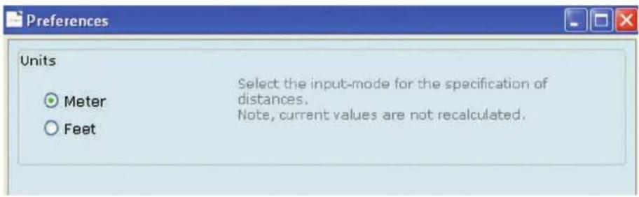
Verify that you are using the correct measurement units
Misc Tab
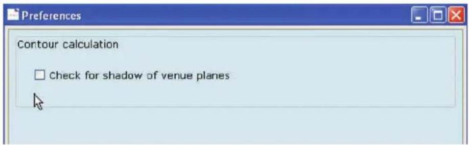
By checking this box a shadow will be cast behind venue planes if they are raised above floor level
Help
Here you will find programme info, including version number and a copy of this user manual in PDF format. The first step is to select your QFlex model, using the BeamEngine software is a simple and effective way of selecting the correct model.
Which QFlex system you specify depends on a number of criteria:-
Distance: Farther areas you wish to reach will require a larger QFlex column. Typically, as a rule of thumb a QFlex 16 will be used to distances of 20m(66ft), and a QFlex 48 in excess of 80m(260ft)
Low Frequency Control: The larger the QFlex column, the more effective control at lower frequencies can be achieved. This also goes for effective steering control at lower frequencies. QFlex 16 (700Hz) >>>> QFlex 48 (200Hz)
SPL Requirements: The larger QFlex arrays will have the ability to produce higher SPL levels.
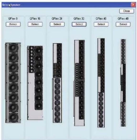
For the purposes of this tutorial we will choose A QFlex 32
6.2 LAYING OUT VENUE PLANES
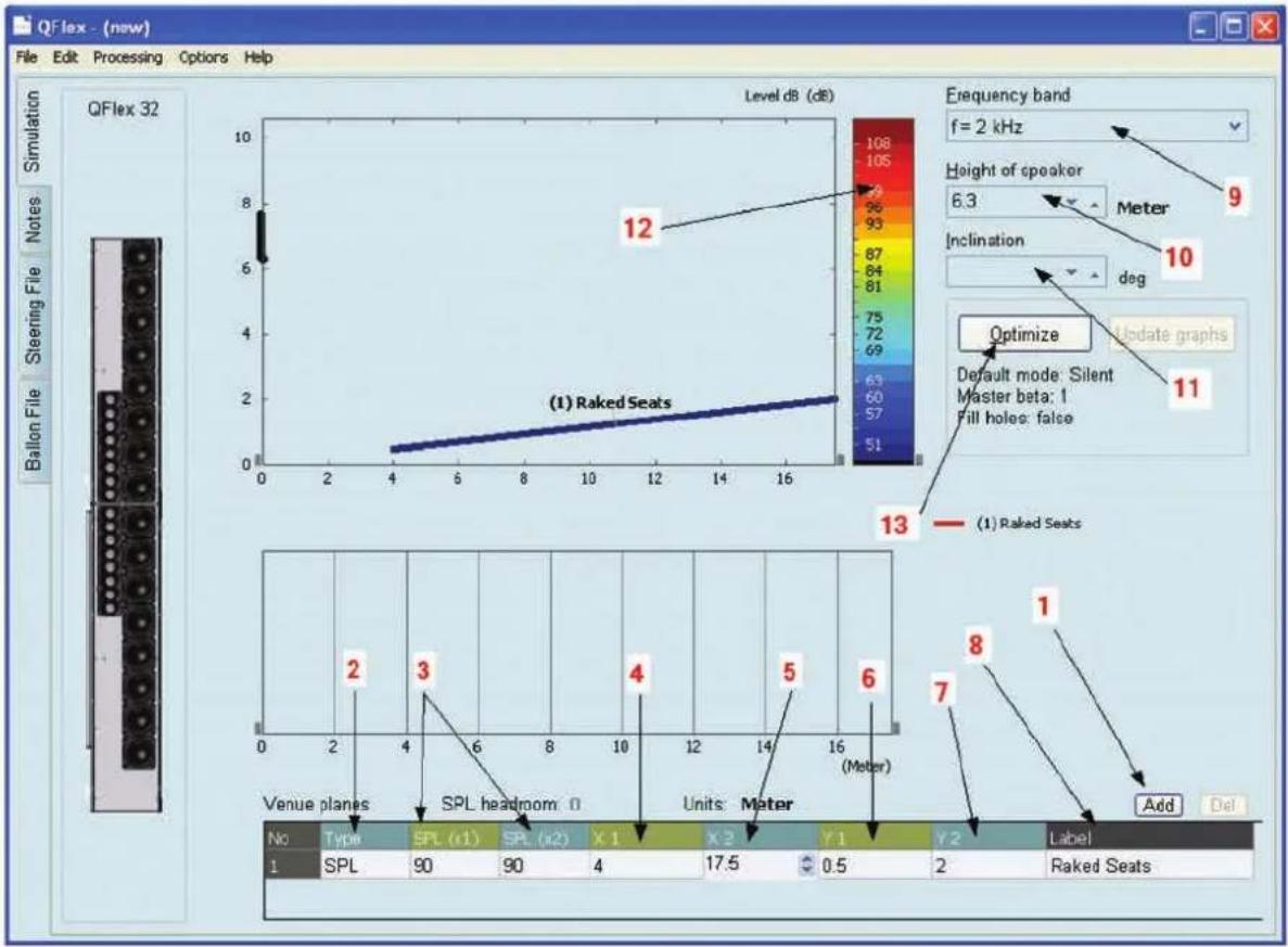
- Click on ADD to create a new venue plane(s)
- Choose SPL to target this particular area from the loudspeaker.
NB. Other Options here are
Silent – This is basically a probe to view the out of beam attenuation on the SPL map. Don't Care - In the straight forward default case the steering algorithm will aim for silence in all unspecified directions, the user can specify areas where avoiding areas does not matter, for example, areas of high absorption. This may improve results elsewhere, but any differences will be marginal.
- SPL (x1) is the front, and SPL (x2) is the rear of this specified venue plane. Specify your target/desired SPL here. Specifying these levels has nothing to do with setting absolute volume levels. After optimization you will be notified if there is enough headroom to reach your desired SPL. Manipulating these two levels allows you to adjust the intensity of the sound beam across the specified venue plane. Normally the goal is to achieve an even SPL distribution across the whole venue plane.
Hint: Where even coverage is required over large areas, splitting the venue plane into two sections may yield better results. In this instance you are effectively creating two separate beams which you can manipulate independently, giving you more control. Again, the goal is to achieve an even SPL distribution across the whole venue plane.
-
The first X co-ordinate of the venue plane.
-
The Second X co-ordinate of the venue plane.
-
The First Y co-ordinate of the venue plane.
-
The Second Y co-ordinate of the venue plane. (You may have a sitting or a standing audience. Remember to factor for the listening height when specifying the Y coordinates.)
-
Here you can label your specified venue plane. This is especially helpful if you have multiple target areas.
-
Frequency Band – To view the beam steering characteristic at different frequencies you can view octave bands or the following averages; Broad-Band(125Hz – 8kHz), Low-Band (125Hz - 1kHz), Mid-Band(250Hz - 2kHz), High-Band (1kHz – 8kHz)
Note: Longer arrays will have better low frequency control characteristics
- Set the height of the loudspeaker. The specified height is to the bottom of the array.
Hint: QFlex will invariably be installed in architecturally sensitive environments. The client or architect will most probably impose restrictions on preferred mounting locations. Beware of mounting the loudspeaker too low. The venue will most probably be empty when you demo or commission the project. If you are in a house of worship, remember that people stand up and sit during a service. Make sure that when people stand they are not masking the sound at the back of the room.
-
Inclination – Not all mounting surfaces are plumb and straight. This feature will allow the programme to factor for any inclinations in the mounting surface.
-
The SPL scale can be referenced against the resultant SPL maps.
-
Optimize: Will generate the steering algorithm based on the supplied information.
6.3 OPTIMIZE RESULTS

- Resultant Beam based on target data. From here you can save the steering file and upload to the QFlex hardware from the VNET software.
- SPL distribution over target area. To further optimize this particular design the SPL intensity towards the back of the room can be increased slightly to give a more even SPL distribution. Splitting the venue plane into two sections may also yield better results. This effectively creates two separate beams which you can manipulate independently, giving you additional control.
- SPL Headroom. Indication of SPL headroom available in the design. This figure will show red if the specified SPL cannot be achieved.
6.4 ADDING ADDITIONAL VENUE ITEMS
heatmap
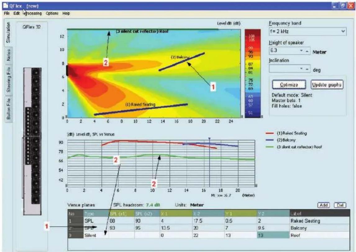
| Venue planes | SPL (x1) | SPL (x2) | X 1 | X 2 | Y 1 | Y 2 | | ------------ | -------- | -------- | --- | --- | --- | --- | | No | 68 | 90 | 4 | 17.5 | 0.5 | 2 | | SPL | 93 | 95 | 13.5 | 20 | 7 | 9.5 | | SPE | 0 | 0 | 0 | 22 | 13 | 13 | | Silent | - | - | - | - | - | - |- Here we have added a second venue plane, in this case a balcony. BeamEngine will automatically target the second venue plane (no need to specify opening angles or steering angles). Note that the intensity of the second beam has been manually increased to mach the SPL of the first venue plane. Both beams can be independently manipulated in this way. Additional venue planes can be added as necessary.
- By specifying a 'Silent' venue plane, in this example placing it on the roof, you can view the amount of 'out of beam attenuation' at any point in the venue. "Reflector" is labeled a surface if it normally points downwards, i.e. it is part of the ceiling. "Cut" is labeled a surface if it is illuminated by the speaker only partly.
6.5 PROBES
heatmap
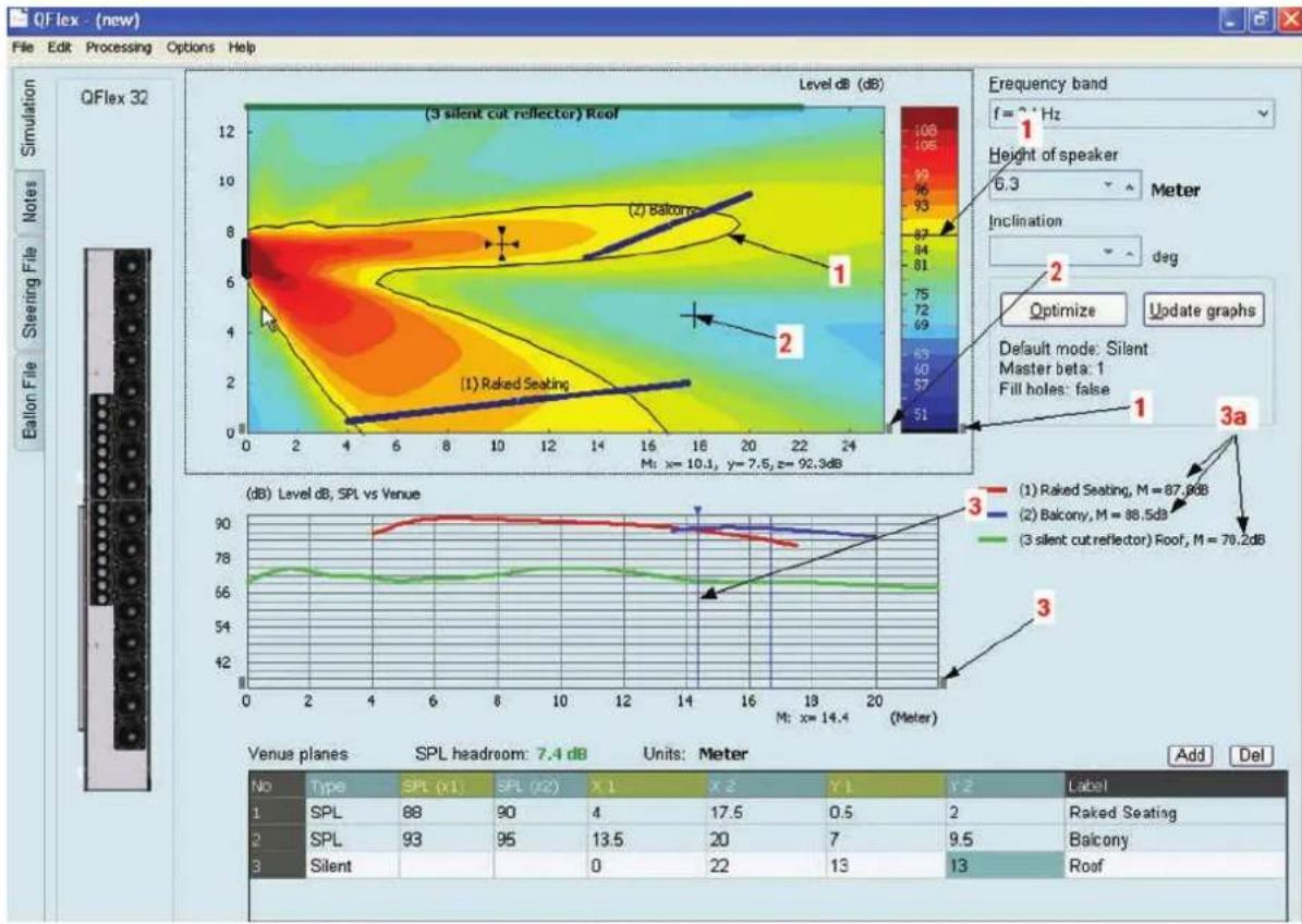
| Level dB (dB) | 0 | 2 | 4 | 6 | 8 | 10 | 12 | 14 | 16 | 18 | 20 | 22 | 24 | |---------------|------|-------|-------|-------|-------|-------|-------|-------|-------|-------|-------|-------|-------| | 1 | | | | | | | | | | | | | | | 2 | | | | | | | | | | | | | | | 3a | | | | | | | | | | | | | | | 3a | | | | | | | | | | | | | | | 3a | | | | | | | | | | | | | | | 3a | | 87.9dB| 88.5dB| 70.2dB| | | | | | | | | | | 3a | | 88.5dB| 70.2dB| | | | | | | | | | | | 3a | | 88.5dB| 70.2dB| | | | | | | | | | | | 3a | | 88.5dB| 70.2dB| | | | | | | | | | 70.2dB| | 3a | | 88.5dB| 70.2dB| | | | | | | | | | 70.2dB| | 3a | | 88.5dB| 70.2dB| | | | | | | | | | 70.2dB| | 3a (darker) / (line) / (depth) / (line) / (line) / (line) / (line) / (line) / (line) / (line) / (line) / (line) / (line) / (line) / (line) / (line) / (line) / (line) / (line) / (line) / (line) / (line) / (line) / (Line) / (Line) / (Line) / (Line) / (Line) / (Line) / (Line) / (Line) / (Line) / (Line) / (Line) / (Line) / (Line) / (Line) / (Line) / (Line) / (Line) / (Line) / (Line) / (Line) / (Range) | | Venue planes: SPL headroom: 7.4 dB Units: Meter No Type SPL X1 SPL X2 X1 X2 Y1 Y2 Label 1 SPL 88 90 4 17.5 0.5 2 Raked Seating 2 SPL 93 95 13.5 20 7 Baicony 3 Silent 0 22 13 Roof Add Del- Click on the small grey box shown. Drag the line on the SPL key to draw the isobar into the display. The isobar corresponds to the position on the SPL graph.
- Click on the small grey box shown. Here you can drag and drop the crosshairs shown. Their corresponding co-ordinates and SPL are shown directly below the SPL map.
- Click on the small grey box shown. Drag the blue probe horizontally across the SPL graph. The SPL across each venue plane is shown at 3a.
6.6 SAVING STEERING FILE

When you are ready to save your steering file, click on the 'Steering File' tab. The name of the file automatically defaults to the QFlex model you are using. In this case 'QFlex 32.bef'. A steering file is saved for each module in the array and given an individual number. For example, when you save the steering file for a QFlex 32, two files will be saved (QFlex32_box1.bef and QFlex32_box2.bef). Any number of steering files can be saved and quickly uploaded to your QFlex hardware individually. Instructions for uploading your steering file are covered in the 'Using Podware' section.

6.7 BALLOON DATA
EASE™ and CATT Acoustic™
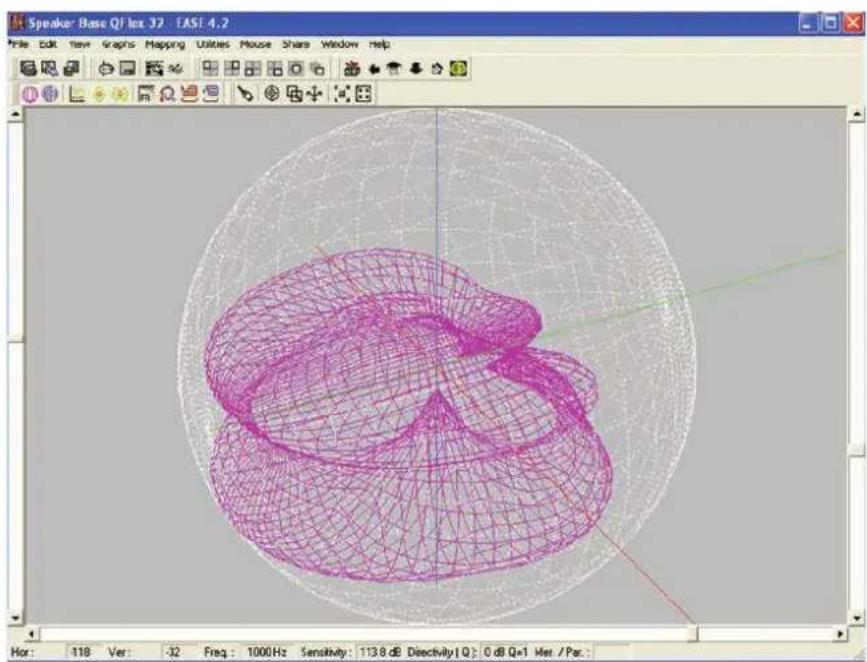
Where more than one QFlex array is deployed in an installation it may be necessary or demanded to carry out a more resolute acoustical analysis of the room. To properly evaluate QFlex coverage in 3D you can export a configuration file from BeamEngine which can be used in Ease™ and CATT Acoustic™

Click on the 'Balloon File' tab.
The name of the file automatically defaults to the QFlex model you are using. In this case 'QFlex32.xhn' This name can be modified. The file is saved in ASCII format and can be imported into the third party programme and the resultant balloon data viewed.
natural_image
3D wireframe model of a mechanical component in a modeling software interface (no text or symbols on the model itself)6.8 BEAMENGINE - FREQUENTLY ASKED QUESTIONS
Q. If I'm adjusting Master Beta, what LF driver utilization compromises do I suffer in adjusting to less than "1"?
A. Master multiplication factor to apply to regularization factors beta given in global A.wf(woofer) and A.tw(tweeter). Normally masterbeta = 1, but it can be reduced to 0.1, trading some SPL for sharper directivity at the lower end of each sub-array's (tweeter or woofer) working range. The default settings will be fine in almost all applications.
Q. Why do some SPL plots of different surfaces further into the room start from the X = 0 position?
A. The SPL-curves report the sound pressure along the venue items. For curves of ceiling venue items (pointing downwards) it does not make sense to position these along the x-axis, so all ceiling items start at x=0.
Q. I noticed that I can skew the coverage pattern of the array by putting in differing SPL values for any SPL surfaces. Any caveats in doing so? I'm just trying to steer a bit more energy onto the balcony front where the sound booth
A. You can vary the intensity of each beam separately as well as adjust the intensity from the front to the rear of each audience plane. You should also treat the target SPL inputs (SPL (x1) & SPL (x2)) as a tool to vary the intensity of the respective beams.
6.9 SOME DESIGN TIPS
In many applications a larger QFlex model at the front of the building will suffice. A single QFlex model has the capability of generating a number of independent beams and creating even SPL distribution over very large areas, so no need for delay loudspeakers.
Beware of mounting the loudspeaker too low. The venue will most probably be empty when demonstrating or commission the project. Remember that people stand up and sit. Make sure that when people stand they are not masking the sound at the back of the room.
For effective vocal reinforcement in venues with very long reverberation times, do not be tempted to use too small an array. A QFlex 16 has effective steering control above 700Hz. The content of many vowel sounds occur below 700Hz. If the RT60 is particularly high, consider using a larger QFlex array.
Even in highly reverberant environments QFlex is capable of directing sound in a laser like manner. Sometimes to create some ambience it may be necessary to widen the beam slightly to create a natural sounding experience.
In very large venues where there may be features of the building which shadow the direct sound, for instance columns. Using smaller delayed QFlex models may be necessary to provide complete coverage. Remember – there is 1000ms of delay on board.
For more upbeat program materiel including music it may be necessary to compliment the QFlex with a subwoofer. As part of the VNET family QFlex can be networked with a VNET Subwoofer if necessary.
7 INSTALLING VNET SOFTWARE (PODWARE)
The latest version of Podware can be found at www.tannoy.com. Any new updates will automatically overwrite any existing versions.
- Having downloaded the software, double click on the 'Setup.exe icon. The welcome screen will appear. Click

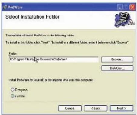
- Select your destination Folder. Click
- Confirm Installation. Click

- If you accept the licence agreement check 'I Agree' and Click

- The programme will begin installing

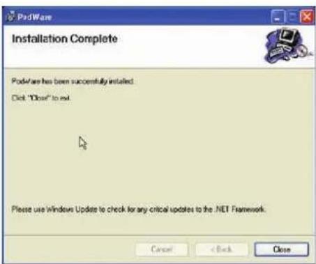
- Installation Complete
8 USING VNET SOFTWARE (PODWARE)
Podware is a software package running under PC Windows ^™ for setting up and controlling any Tannoy VNET device.
It is a clean Object Oriented package using the latest development technologies yielding intuitive ease of use and all the features you have come to expect and more. Podware is used for configuring installations as well as the live control and monitoring of devices during use. These devices may be connected individually using RS232 or USB. When participating in a networked system, Podware can control many devices via RS485 and Ethernet.
Podware is a precision tool for system control and is capable of being configured to display single controls and indicators, full interactive device panels or whole network views. Indeed, when networked, Podware can display information and controls from multiple devices on the same page.
8.1 OVERVIEW
The VNET PodWare application will allow a PC computer running a 32-bit Windows™ operating system (NT, 2000, XP, Vista, ME*, 98*) to monitor and control a number of compatible devices via communications network. The deceptively simple intuitive user interface is PodWare's outward appearance of a very powerful, thoroughly engineered protocol engine, built on the latest software development technology.
PodWare can automatically discover devices connected to the network you tell it you would like to use. The connected devices are then presented to you in an organised tree ready for you to select panels you would like to display and manipulate
When devices are arranged in the main window, their default representation is a Monicon - an Icon which conveys basic monitoring status indication. This Icon can usually then be opened up to the full control panel by clicking on a navigation button.
Any number of Monicons and full panels may be displayed and organised on the screen automatically or manually. Each device type usually has a predefined Monicon and control panel associated with it, the latter containing controls for all the parameters you can adjust within the device. Adjusting any of the controls on the panel whilst 'on-line' will cause adjustments to be made in the relevant device in 'real time'. A comprehensive set of features allow you to save and retrieve stored parameter sets, manipulate 'presets', etc.
*Note that whilst operation with Windows™ 98 or Millennium Edition is theoretically possible, this is not recommended because of the resource limitations these operating systems impose. If this is attempted, you should not attempt to run any other applications at the same time as PodWare, and we would recommend that you only open one or two control panels at a time.
8.2 LAYOUT
When PodWare is launched, its main window comprises three main areas:
- A 'tree' panel on the left for navigating among devices and panel
- A toolbar at the top with the most commonly used actions available at a single mouse click
- A control panel area (the remainder of the window) for device Monicons and control panels.
The user may adjust the size of the application window by dragging the handle at the bottom-right of the main application window. The 'tree' panel may be sized by dragging the split-line between the tree and the main control panel area.
8.3 MENUS
The menu system is arranged like so:

File
Open - opens a file which contains parameters for the selected device Save - saves the current settings for the selected device in the current file name Save As - saves the current settings for the selected device under a new file name Load Factory Settings – updates factory settings in the selected device (See Loading Factory Settings) Open Device Clone – opens a file to clone the selected device Save Device Clone – saves the settings of the selected device into a cloning file (See Cloning a Device) Exit - closes the application
Preferences
Show Bandwidth As – Allows you to set the units used in Bandwidth controls Show Delay As – Allows you to set the units used in Delay controls (See Controls)
Network
Go Online - Allows communication with devices on the network Go Offline - Stops communication with devices on the network Com Port - Allows you to select which serial COM port you wish to use Launch Panels - Launches the control panels for all the devices in the network
Device
Locate – to locate the selected device (e.g. wink the lights) Update Firmware - update firmware in the selected device (See Device Firmware) Add Device Panel – allows a panel for a device to be added to the layout off-line Properties – Lists device details which may be of interest for maintenance (See The selected Device)
Panel
Tile Horizontally – arranges all the panels from left to right Tile Vertically – arranges all the panels from top to bottom Cascade – arranges all the panels in a heap from top-left to bottom-right
Help
Help topics – opens the help file (in your HTML viewer) About this Application – shows copyright and version information
Some of these menu items have short-cuts using toolbar buttons. See Toolbar
8.4 TOOLBAR
The toolbar provides the following one-click functions:
Open
Opens a file which contains parameters for the selected device. A dialogue will appear, inviting you to choose a file to open.
Save
Saves the current settings for the selected device. If you have previously opened or saved a file, the settings will be saved in the same file name, otherwise, a dialogue will appear inviting you to enter a file name. If the settings have not changed since you last saved or opened a file, the Icon will appear greyed out, indicating that a save is not necessary.
Online
Goes online/offline to/from the network. If a device cannot be found, an error will be reported. While PodWare remains on-line, this toolbar button is coloured green. It is red when off-line.
Locate
Flashes the indicators on the selected device (if online), to assist device identification, and as a quick check that communications are working. This only works when on-line.
Mute All
Mutes (or Un-Mutes) every device in the system. When the speaker in the button is red, the system is muted. A green speaker means un-muted. This has nothing to do with channel mutes, which operate completely independently. This state is not saved in devices; a power cycle will cause a device to default to un-muted.
Launch All Panels
Launches the control panels for all of the devices on the network. This only work when on-line.
Help
Launches Help topics
If you place the mouse cursor over a toolbar, text fill appear describing the action of the button. If this text does not show, click on the panel background.
See The Selected Device
8.5 COMMUNICATIONS
PodWare communicates with a device using a serial 'COM' port as a 'network' connection. This will usually be the COM port associated with the RS232 Serial port on your computer. You need to select the appropriate COM port for this in the Network menu.
If your computer does not have an RS232 serial port, a USB or Ethernet adapter may be used to create one. Such an adaptor needs to create a 'Virtual Com Port' in order for it to be used with PodWare. Please refer to the installation instructions supplied with the adaptor. We cannot guarantee that all adaptors will work correctly however. Please consult your dealer for recommended adaptors.
It is strongly recommended that you use the dedicated Tannoy USB/232 interface (Tannoy part number 8001 4450). The user manual & drivers for this device can be found at www.tannoy.com.
When a network connection is open and actively connected to one or more compatible devices, the system is said to be 'On Line'. Whilst On-line, you can control the connected devices in 'real time', and continuously receive status information from the devices.
To go On-line, you can either select Device/Online from the menu, or press the Online toolbar button, which is a red triangle. If all is well, the triangle will turn green, indicating that you are 'On-line'.
Going Online
PodWare queries the network, searching for compatible devices. As PodWare finds each device, it will add it to the 'Devices' node of the Tree, along with text describing the model of the device, and the name of the device given by the user. Once all devices have been discovered, you are ready to start controlling the system by double-clicking a device icon in the Tree to launch a control panel.(see Launching a Panel)
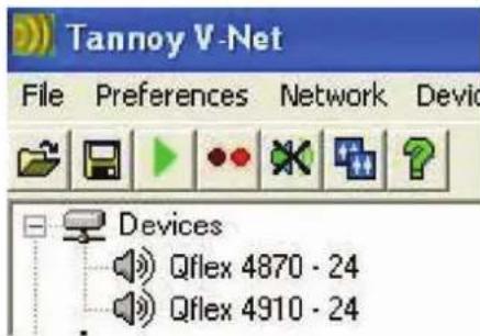
If PodWare becomes unable to communicate with a device for some reason whilst on-line (such as a break in the network cable), the corresponding icon for it in the Devices node of the Tree will appear in red, indicating that control and monitoring on that device is invalid. Most devices will allow themselves to be 'rediscovered' automatically if such a cable break is repaired.
8.6 LAUNCHING A PANEL
Once the application is On-Line, and there are one or more devices in the Devices node of the tree, a panel may be launched for a given device in one of the following ways:
• By double-clicking on the appropriate Devices node of the Tree
• By dragging a Devices node to the Layout area of the main window
• By dragging a Devices node to the Panels node of the Tree
- By right-clicking on the Devices node and selecting Launch Panel from the context menu (see Device Context Menu)
- By selecting Launch All Panels, either from the Toolbar (see Toolbar), or from the Network menu (See Menus)
After a few seconds, the panel (or more usually, the reduced-size Monicon – see Monicons) will appear in the Layout part of the main window. At the same time, an icon for the device will appear in the Panels node of the Tree. Once the panel appears, the application will take a few seconds while it copies the settings in the device to the control panel, as indicated by the progress bar at the bottom-right of the main window. (See Parameter Synchronisation)
This is now a fully functional real-time control panel for the connected device. A Monicon may be enlarged to a full-size control panel by using navigation buttons. (See Navigation).

Several control panels may be launched onto the Layout, so that the user can monitor the operation of several devices simultaneously. As each panel is added, another icon is added to the Layout node of the Tree, indicating the presence of another panel in the Layout.
The Panel menu has features for arranging the panels into regular neat patterns if required (see Menus).
To locate a panel for a particular device, just double-click on its icon in the Panels node of the Tree. This will bring the associated panel to the front, and highlight it (bring it into focus). (See Navigation).
A panel may be removed from the Layout by clicking on the 'X' in the top-right corner of the panel. This action will also remove the device icon from the Panels node of the Tree. The panel may be launched back onto the Layout by double-clicking on the Devices icon in the Tree.
8.7 CONTROLLING DEVICES – A QUICK OVERVIEW
When online the tree menus will show the connected VNET speakers on the network. Double clicking on the model on the tree view will open the control panel for each respective device. Each open panel will also appear on the tree view under panels. When online, Podware gathers information from the connected devices. Any parameters which have been adjusted by the user in previous sessions will be shown.
Each control panel can be positioned on the screen to represent its actual location position in the venue. When saving data the control panels co-ordinates are also saved so that it appears in the same location on the screen when data is recalled (see saving & recalling data).
The panels shown on the screenshot allows you to view what is going on inside the VNET product. As well as a mute button, there is a limiter meter which indicate signal level relative to the limiter threshold setting, input level meter, draw on the power supply, driver status indicators showing the status of each driver.
The arrow button (>>) at the top right hand side of the control panel will expand the control panel to reveal a host of parameters which can be viewed & adjusted.
8.8 PARAMETER SYNCHRONISATION
PodWare aims to always ensure that the control settings in the virtual control panel are always a faithful representation of the settings in the connected device. To achieve this, the parameters in the device are copied to the control panel when going online. This takes a few seconds to complete (see Communications and Progress Bar). Whilst online, any changes to the control settings will result in changes in the stored parameters in the devices, thus retaining synchronisation. When a file is opened online, the new settings are not only set in the control panel; they are also transferred to the device
8.9 PROGRESS BAR
The area in the status bar at the bottom-right of the application window will indicate progress of some operations. A coloured bar will extend to fill the extreme right-hand box, indicating progress from 0 to 100%, after which it will disappear. While in progress, the text to the left of the bar will indicate what operation is being performed. "Loading" will often be shown to indicate that the data is being transferred between the device and PodWare.
While the Progress Bar is showing activity, it is best not to perform any other actions in PodWare.
8.10 NAVIGATION
The Tree view on the left-hand side of the screen allows you to view the system. The two main nodes in the Tree are Devices, listing all the compatible devices found on the network, and Panels, listing all the control panels that have been launched onto the Layout. Control panels may be launched by double-clicking on, or dragging a Devices node (see Launching a Panel).
Clicking the '-' on one of the main Tree nodes will close that branch, allowing you to remove some detail from the Tree. Clicking the '+' will restore the full detail.
Panels will often have navigation buttons for changing the amount of detail seen (and size of the panel). A Monicon panel will have a ‘>’ button for expanding it into a full control panel. Similarly, a full panel will often have a ‘<’ button for reducing the amount of detail (and panel size).
8.11 THE SELECTED DEVICE
The "Selected Device" is the device to which operations from the Device menu will be applied, and to which device-related toolbar button actions (such as Locate, Save, Open) will be applied.
If a device is selected in the Tree view (by clicking on a device node or a panel node so that the text of the node highlights), then this is the selected device. If no device is selected in the tree, then the control panel in focus (the one whose colour is different to the others) will be the selected device. If there are no panels in the layout, and no device is selected in the Tree view, then no device is selected, and device-related operations will not work.
8.12 DEVICE CONTEXT MENU
By right-clicking on the node of a device in the Tree, a 'context menu' will appear, providing you with the following possible actions:
- Launch Panel – Launches the control panel for this device
- Rename Device – Allows the Device Name to be changed
- Update Firmware - Update firmware in this device (See Device Firmware)
- Locate Device – To locate this device (e.g. wink the lights)
- Properties – Lists device details which may be of interest for maintenance
If you do not wish to select any actions from the context menu, it can be dismissed by pressing the ESC key, or by clicking the mouse anywhere else in the application window.
8.13 CONTROL PANELS
Each panel will have a complete set of controls relating to the adjustable parameters within the device. Each control will contain the current parameter value (See Parameter Synchronisation). In some panels, Tabs are used to distinguish between different sections of the device.
Single parameters may be adjusted 'live' whilst 'On-line'.
Also see Controls
Panels will often have a tool bar, with buttons for executing commonly used functions such as File Open, File Save, Locate and Help (see ToolBar).
Main Control Panel
The EQ / Delay tab allows you to adjust the cabinet equalisation, High-pass filter, and delay. The cabinet equalisation allows you to adjust the frequency and Gain (boost/cut) for each of the equalisation filters, and the bandwidth of the parametric equalisers. The latter controls allow the responsiveness of the filters to be adjusted either as Octaves or Q, depending on the setting of Preferences>Show Bandwidth As. There is also a Low-shelf and a High-shelf filter, each with Frequency, Slope and Gain controls. A 'Frequency Response' curve shows the shape of each filter individually (by colour), and the combined effect of all equalisation (in white).

The Setup Tab - The steering file may also be loaded in this tab. See Loading Steering Data
The Properties/Options tab contains some properties of the loudspeaker. Here, you can enter a name for the loudspeaker (such as "Front Left"), and a name for the configuration (such as "EQ 8-11-2008"). Also viewable in this tab is the model name of the loudspeaker. The Maintenance area shows some details of how the loudspeaker has been used, with various counts of use and abuse.

The Logs area contains graphs of events against time, recording events over a period of up to three days. Since the loudspeaker cannot record any events whilst powered-off, breaks in a log due to power-downs are indicated by a discontinuity symbol 'll' in the log. The events recorded are: Thermal, which is the used thermal capacity, Amplifier Protect Gain, which is a measure of how much the loudspeaker is 'dimming' itself in order to protect itself from potential damage, Driver Protection, which is a measure of how much the loudspeaker is 'dimming' itself in order to protect the drivers from damage and Supply, which shows how the mains power voltage compares with nominal voltage. The data in a log can be exported by right-clicking on the log to launch a context menu, and selecting "copy log data to clipboard". The data could then be pasted into a spreadsheet for further analysis. Your dealer may ask you to do this is you have experienced a problem. Note that in addition to showing amplifier protection due to over-heating, the Amp Protection log will also show protection of individual amplifiers if they attempt to drive into an open circuit (if a driver has 'blown'). This will be shown as a protection gain of approximately -9dB.
Power Save
At the bottom left hand corner of the control panel there is a power save button. Activating this button will shut down the amplifier into a lower-power standby mode. The DSP section remains active. If you set the Power Save control to anything other than Manual, the loudspeaker will automatically go into power-save mode after a period without any audio signal, the time being set by this control. Whenever a signal is applied in this mode, the loudspeaker will rapidly wake-up.
You can change the view to the MonIcon panel by clicking the “<<” button.
8.14 LOADING STEERING DATA
Steering Files are generated in the BeamEngine software package (See Using BeamEngine)
The steering properties of the loudspeaker may be adjusted by loading a 'Beam Engine File' (*.bef) in the Setup tab in the main control panel. When the 'Open File' button is clicked, a dialogue will allow you to load a new .bef file. If there is more than one loudspeaker 'box' in the column, each .bef file produced by the beam design software will be for a given box. The box number will usually be appended to the name of the file. The number of each box is shown to the right of the device name in the Monicon. It is very important that each file is loaded to the appropriate box.
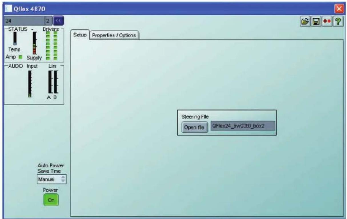
Note that when steering data is loaded into a loudspeaker, the data has to be stored internally, which takes a finite time. To avoid loss of steering data, do not remove the power from a loudspeaker for at least ten seconds after loading steering data. The same applies if you are loading a .dse Settings file which has steering data embedded into it.
8.15 MONICONS
Monicons are a condensed representation of a device, which show some monitoring status information, but few or no controls. Since these are quite small, they are a convenient way of arranging the devices on the main window in a manner meaningful to the application. Clicking the > button will cause the full control panel for the device to be displayed. (See Navigation).
This allows you to view what is going on inside the loudspeaker at a glance. There is a pair of input signal level meters showing the input signals, signal level meters for each group of drivers in the cabinet which indicate signal level relative to the limiter settings, a thermal meter showing the used thermal capacity of the amplifiers, and amplifier status indicators showing when an amplifier is protecting itself from damage due to abnormal operating conditions, and Driver indicators showing when the impedance of a driver is outside normal range, laid out in the same way as the physical drivers. Generally, the indicators show green whilst all is well and red when something is wrong.
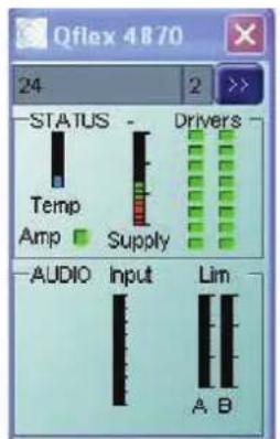
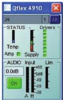
Note that the Input meter on a Master displays the absolute signal level (in dBu) present on the input connector, and is unaffected by the input gain control. The input meter on a Slave displays the level of the signal passed to it by the Master, relative to full-scale, and is effected by the input gain on the Master. You may also mute the loudspeaker, and see the input gain. The gain can also be changed by typing a value into the Gain box. You can change the view to the main panel by clicking the “>>” button. At the top of the MonIcon, the name of the device is shown, and to the right of this, the number of the box so that each box may be identified in a multi-box column.
8.16 CONTROLS
Controls have standardised properties that allow them to work in a consistent way across various control panels for different devices. Many controls will allow the mouse wheel to be used for fine adjustments, or the keyboard as an alternative (see Keyboard Shortcuts). When using the keyboard or the mouse wheel, it is necessary to have the control in question 'in focus'. You can bring a control into focus either by tabbing to it (using the Tab key), or by clicking on it with the mouse. Focus is often shown as a dotted rectangle around part of the control, or by the text in a control being highlighted, or by a solid outline being added to a button. Some controls may allow the units of measure used for displaying and adjusting values to be changed, such as Equaliser Bandwidths, which may be shown in Octaves or Q, or Delays, which may be shown in distance or delay units. The units of measure are selected in the Preferences menu (see Menus).
Drop-Down Selector boxes
These are for selecting one item from a number of possibilities in a list. Click the arrow on the right-hand end of the control to cause it to display a list of the options. Click on the text for that option to select it. If there are many options to choose from, a scroll-bar will be shown, allowing you to scroll up and down the list by clicking the scroll arrows. Note that once the control is highlighted, the PGUP, PGDWN and Arrow keys or the mouse wheel may also be used to change the selection.
Spin boxes
The value would normally be adjusted by clicking on the top button to increase the displayed value, or on the bottom button to reduce the displayed value. Holding the mouse button whilst on a button will after a short delay cause the repeat mechanism to repeatedly increment or decrement the value. Alternatively, values may be typed into the value box directly. To do this, click in the value box and type in the new value. The value you type in may include a minus sign, a decimal point, and/or an engineering multiplier, such as 'k' to signify a multiplication of 1000. This may appear at the end of the typed string, or may be used instead of a decimal point (such as 6k2 to mean 6200). Some controls may auto-range as the value changes. For example, delay controls in distance mode may change from mm to m as the distance increases beyond 999mm. If you wish to type a value into such a control, then metres will be assumes unless you specify mm (such as "53mm"). For the value to be accepted, you can either click outside the control (such as on another control), or press the Enter key. Once s control button is highlighted, the PGUP, PGDWN and Arrow keys or the mouse wheel may also be used to adjust the value.
Buttons
Buttons generally have two states; depressed (active) and non-depressed (inactive). Generally, the button will apply the condition that is labelled when it is depressed. The space bar may be used to activate a button which is in focus.
Radio buttons
These are laid out in mutually exclusive groups to select one of a number of options. Press the radio button to select it, which will cause any other button in the group to be deselected. Once a control in the group is highlighted, the PGUP, PGDWN and Arrow keys may also be used to change the selection.
Faders
Faders provide a linearly traversing button, which may be dragged using a pressed mouse to adjust the value. These sometimes also have an associated value box for showing the numerical value of the parameter. Once the control is highlighted, the PGUP and PGDWN keys may be used for coarse adjustment, and the Arrow keys or the mouse wheel may be used to for fine adjustment.
8.17 FILTER RESPONSE PANELS
Some panels provide a graphical representation of the response of one or more of the filters/equalisers in the device. These will usually consist of coloured semi-transparent filled areas representing individual filters, overlaid with a white curve line representing the overall response of a bank of filters/equaliser sections.
When the associated filter parameters are adjusted, you will see the curves responding so they always show the current response.
It will usually be possible to 'drag' the filter parameters with the computer mouse directly on the Response Panel. If you click anywhere in a Response Panel, you will see a set of 'drag handles' appear at the apexes of the individual filter response curves. These handles will usually have the same colour as the filter they relate to, and carry a number or letter to assist identification.
To change a filter parameter, place the mouse pointer over the drag handle, then press and hold the left mouse button while moving the mouse (vertically to change the filter gain, and horizontally to change the filter frequency). The filter With/Slope/Order may be adjusted either using the mouse wheel, or by holding the keyboard shift key whilst dragging the handle vertically.
The keyboard may also be used (see Keyboard Shortcuts).
Copy Graphics
To assist in preparing documentation etc, any response panel may be copied (to the Windows clipboard) by right-clicking on the panel and selecting Copy Image to Clipboard. The bitmap image may then be pasted into another application (such as word-processing), usually by selecting Edit>Paste in that application, or CTL+C.
Copy/Paste Settings
You can copy EQ settings from one channel to another on a given device, or copy EQ settings from one device to another. To do this simply right-click on the source panel (the one you want to copy from) and select Copy EQ Settings. Then on the destination response panel (the one you want to copy to), right-click and select Paste EQ Settings. You will be alerted to any problems such as the destination response panel not having enough EQ bands to reproduce the source EQ, or access to some or all of the bands being restricted due to security protection.
You may launch a control panel for a device whilst off-line be using the menu feature Device>Add Device Panel. Clicking on this will cause a dialogue to be shown which allows you to choose the particular model of device you would like to add to the layout. Once you have chosen the model, click the Add button. The application will then be busy for a few seconds while the panel is constructed, after which it will appear in the Layout part of the window, and an icon for it will be added in the Panel part of the Tree. More device panels may then be added by making further device model selections and clicking Add. When you have added all the panels you need, click the Done button to dismiss the dialogue.
Off-line operation is useful either for demonstration or product familiarisation, or for creating setting files when a real device is not available.
Settings made on an off-line panel may be saved to a settings file by clicking the file Save icon on the panel. Similarly, a settings file may be loaded into the panel for further modification.
Note that when you go on-line to a network of devices, any off-line panels will first be dismissed. You can of course load a settings file you created offline into a device when on-line (See Saving Data).
8.19 SAVING & RECALLING DATA
Device Data may be saved to disk or opened from disk. PodWare Device Settings files (with file extension .dse) contain all the user data necessary to restore a device to exactly the same state as when the file was saved.
If the current settings have been changed since the last file save or file open, the Save Icon on the panel toolbar will be shown in solid colour. If the settings are already safe, the Save icon appears grey.
If a file is opened when on-line to devices, the new data will be sent to the device, overwriting whatever was in the device. A warning will be given before this is done. Data saved from one device can be reopened in another to save time inputting data. (Assuming settings are to be duplicated).
When you save a file, you will be invited to include steering data in the file. If you do this, opening the file into the same device or another device will reinstate the same steering settings.
If you do not include steering data, then the user settings such as EQ etc remain independent from steering data. If you open a settings file which contains steering data, a warning will be given that the steering data will be overwritten.
PodWare will always try to protect your data, warning you if you are attempting an action that could cause loss of data.
8.20 LOADING FACTORY SETTINGS
Using the File>Load Factory Settings menu option, you can update the basic factory settings which might be issued in future from Tannoy.
When you load factory settings into QFlex, the current user settings will be preserved since the factory settings will only overwrite the factory DSP settings rather than the User DSP settings. Depending on what type of file is supplied, the factory file may or may not include steering data. A warning will be given if you open a factory file which includes steering data, since this will overwrite any existing steering data.
For further information on loading factory settings, please see the main application help.
This procedure will apply to the currently selected device (See The Selected Device). Once you have selected the menu item, you will be guided to select a Device Factory (.dfa) file to load. If you have a control panel for the device in view, this will automatically be dismissed for a time while loading takes place. The progress bar at the bottom-right of the application indicates when the process has finished, after which your control panel will reappear if you had launched one.
8.21 CLONING A DEVICE
There are several different categories of settings within a device which are manipulated by the various file types. The standard Device Settings file (.dse) will only manipulate those parameters which are under the control of the user. More of the settings may be changed by loading Factory Settings (see Loading Factory Settings). However, to create a completely duplicate device whose settings will be identical in every way, the Cloning facility may be used. To do this, select the device which you wish to clone FROM (see The Selected Device), then use File>Save Device Clone.
Once you have selected the menu item, you will be guided to choose a Device CLone (.dcl) file name to save. If you have a control panel for the device in view, this will automatically be dismissed for a time while saving takes place. The progress bar at the bottom-right of the application indicates when the process has finished, after which your control panel will reappear if you had launched one.
Now select the device you wish to clone TO, then use File>Open Device Clone. A similar process to that described above will allow you to chose the .dcl file to open. Once the process is complete, the two devices will be identical.
Clearly for this to make sense, the two device should be of the same type.
8.22 OPERATING MODE
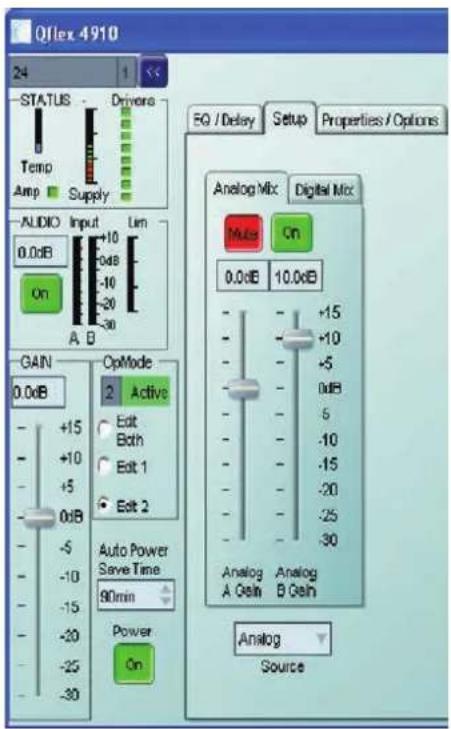
A control input on the back of the loudspeaker allows you to select between two different sets of DSP settings (1 and 2) – see system connectivity. The currently active Operating Mode is indicated by the 'Active' box in the OpMode group box in the PodWare panel. You can select which Operating Mode you wish to edit by selecting the appropriate radio-button in the OpMode group box. Both modes may be edited simultaneously by selecting 'Edit Both'. Only when the Operating Mode is the same as the edited mode will changes you make be heard. Note however that if you make adjustments on the control panel when the active mode is different to the edit mode, the settings are changed and stored in the loudspeaker, but you will not be able to hear the changes until the active mode is changed to the one you have edited. A red indication will be shown in the OpMode group box when you are not listening to the mode you are editing.
Note that Parameter adjustments are automatically stored in the loudspeaker - it is not possible to do temporary changes then store them separately.
Example - Op Mode 1 with a particular EQ setting.
Input B Muted


Example – Op Mode 2 with an EQ setting for emergency paging.
Input A muted.

Protection
Comprehensive protection features preserve the longevity of the amplifiers and drivers by continuously monitoring several critical parameters, and reducing the gain, or muting the amplifiers either temporarily or permanently depending on the nature and seriousness of the fault or misuse. The amplifiers will recover and restart if at all possible, but may remain shutdown if a serious fault persists.
Limiters deal with routine over-driving of the drivers, making sure that the drivers are not pushed too hard.
Minor faults are dealt with by slowly ‘dimming’ the loudspeaker, reducing the level to a sufficient degree and for a sufficient time that the amplifiers are able to recover gracefully without any user interaction. When the fault condition has passed, the amplifiers will slowly fade up to normal.
More serious faults may cause the amplifiers to mute while they recover, after which they will automatically re-energise and fade up, again without user interaction. If such a fault is found to be persistent however, the amplifiers may shut down permanently, flashing an indicator rapidly. A power cycle by the user is then required.
During power-up, the amplifiers will remain muted for a short time while checks are made that all is well. During this time, the Indicator will flash. The signal is then gently faded up.
Indication
Visible from the front of the loudspeaker is a Network indicator, which also winks for a few seconds when the 'Locate' feature is activated in PodWare. This allows you to confirm which control panel in PodWare is dealing with which physical loudspeaker.
Summary of indication:
- During Loudspeaker power-up: Indicator winks rapidly
- Loudspeaker has detected a fault: Indicator winks rapidly
- Locate feature activated in PodWare: Indicator winks
- Mute All activated: Indicator winks slowly
8.23 DEVICE PROPERTIES
By selecting Device>Properties from the menu (see Menus), or by selecting Properties from the Device Context Menu (see Device Context Menu), a dialogue will be shown listing some properties for the selected device (See The Selected Device). These are as follows:
Model Name: The Model Name/Number the type of device is usually known as (e.g. "QFlex 16 Master")
Device Name: The name given to this particular device by the user (e.g. "Left Proscenium"). This can usually be changed in a control panel, or in the Device Context Menu (seeDevice Context Menu)
Settings Name: The name given to the current set of parameter settings (e.g. "Bright vocal")
Firmware Model: A number describing the type of software running in the device.
Firmware Version: The version number of the firmware so you can tell if you have the latest. See Device Firmware
Handle: A 4-digit hexadecimal number which will uniquely identify this device on a network
Link Address: A hexadecimal number which the network will use for addressing this device.
Hardware Version: A number representing a variant of the hardware build of a given device type. This is rarely of concern to the user, but you may be asked to quote this value when discussing a problem with your dealer.
When you have finished with the dialogue, just click the Done button.
8.24 DEVICE FIRMWARE
Firmware is the software which runs inside the device. Most products which are controllable from PodWare have firmware which can be updated by the user.
Firmware is uniquely identified by two things:
- The Firmware Model Number. This is not the model number of the product, but a number which uniquely describes the type of firmware used by the device. When updating firmware, the same firmware model must be used.
- The Firmware Version Number. This describes the issue of the firmware update within a given model number. When updating firmware, the latest firmware Version Number for a given firmware Model Number would normally be selected. Firmware updates are usually supplied in .dfw (Device FirmWare) files. PodWare uses a .dfw file to load new firmware into a device.
Firmware files are named like this: ****5678V1234.DFW
If you are using the very latest Version of Podware then you will be advised automatically when you go online if your device requires a firmware update
You can inspect the firmware Model and Version in the Device Properties dialogue.
To update the firmware in a device, see Menus or Device Context Menus.
At the bottom right hand side of the screen a blue bar will show the progress of the firmware update. Do not power down the unit or disconnect any network cable during a firmware update. During the update a red bar will show the progress of the firmware update (bottom right of screen). The device will then power cycle automatically. The loudspeaker is now ready for normal operation.
8.25 KEYBOARD SHORTCUTS
PodWare supports the following 'shortcuts':
Tab Move to next control
In value boxes:
CTL+C Copy
CTL+V Paste
CTL+X Cut
CTL+Z Undo
On Drop-down, Spin, Push, Fader and radio controls:
PgUp Increase value (coarsely)
PgDown Reduce value (coarsely)
Up/Right arrow Increase value (finely)
Down/Left arrow Reduce value (finely)
On push-button controls:
Space Activate
On Filter Response Panels:
PgUp Increase Width/Slope/Order value
PgDown Reduce Width/Slope/Order value
Up arrow Increase filter gain value
Down arrow Reduce filter gain value
Right arrow Increase filter frequency value
Left arrow Reduce filter frequency value
Tab Move to next filter
Shift Used with mouse drag to adjust Width/Slope/Order value
9 HARDWARE CONFIGURATION (GENERL INFORMATION)
To avoid shipping very long products, QFlex products are modular, so it will be possible to assemble the components of a QFlex product on site. Each QFlex module incorporates a mains power supply, DSP platform with VNET support, and audio amplification.
All of the required joining hardware and bracketry is included with each QFlex purchase. If you have purchased a QFlex 8 or a QFlex 16 there are no connecting plates or other joining hardware. Each QFlex carton is marked to show each modules position in the array.
QFlex modules must only be joined or separated with the complete column laying flat on the ground and disconnected from the mains supply.

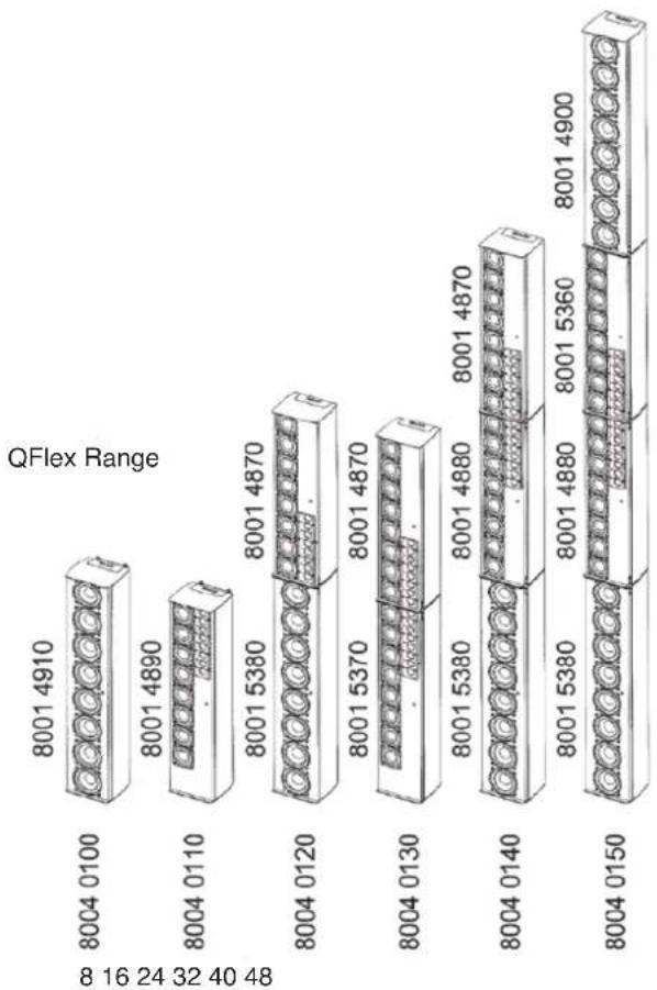
There are 5 individual modules that make up the complete QFlex Range:
a. 8 channel master unit (80014910)
b. 8 channel slave unit (8001 4900)
c. 16 channel master unit (8001 4890)
d. 16 channel slave unit (top) (8001 4880)
e. 16 channel slave unit (bottom) (8001 4870)
bar
QFlex Range | Category | Value | |---|---| | 8004 0100 | 8001 4910 | | 8004 0110 | 8001 4890 | | 8004 0120 | 8001 4870 | | 8004 0130 | 8001 4870 | | 8004 0140 | 8001 4880 | | 8004 0150 | 8001 4900 | 8 16 24 32 40 48The joining hardware parts are packed with the QFlex modules in cardboard boxes which double as carton fillers. These will be marked 'HARDWARE'
The Table below shows the list of joining hardware parts and bracketry supplied with each QFlex model.
| QFlex product | Product number | Cabinet joining plate with hinges 7600 1770 | Joining plate - side (inc 20 screws) 7600 1800 | Joining plate - rear 6883 0267 | Wall bracket 8001 5330 |
| QFlex 8 8004 | 0100 0 0 0 1 | ||||
| QFlex 16 | 8004 0110 0 0 0 1 | ||||
| QFlex 24 | 8004 0120 1 1 0 1 | ||||
| QFlex 32 | 8004 0130 1 1 0 1 | ||||
| QFlex 40 | 8004 0140 2 2 0 2 | ||||
| QFlex 48 | 8004 0150 2 3 1 2 |
- A QFlex array will consist of either just a master unit (QFlex 8 or 16) or a master unit with up to three additional slave units (QFlex 48)
- The master unit will always be positioned at the bottom of any speaker column and will be slightly longer to accommodate the connectors and power indicator.
- The top of the master unit will allow a slave unit to be mechanically fixed to it.
- The bottom of a slave unit will be designed to be mechanically fixed to the top of a master or slave unit.
- The top of a slave unit will be the same as the top of the master unit to allow another slave unit to be mechanically fixed to it.
- QFlex systems may be configured to enter a power saving standby mode either automatically or in response to a VNET™ command, returning to operating mode either upon the detection of audio or a 'power up' VNET™ command.
- QFlex products have analog and AES* audio inputs, and use VNET™ for monitoring and control.
- For mechanical integrity, thermal and EMC reasons, the electronics module is in a separate cavity from the transducers.
• QFlex products are designed to meet the safety requirements of UL60065 7th edition & EN60065 2002. - QFlex meet the EMC requirements of Fcc15a and EN55103* AES inputs will be included as standard in 2009
10 ASSEMBLY INSTRUCTIONS
10.1 QFLEX 8 & QFLEX 16 ASSEMBLY
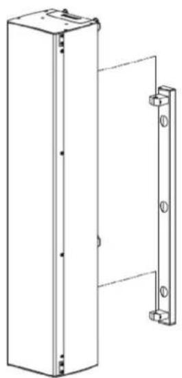
With a QFlex 8 and QFlex 16 all you need to do is remove the loudspeaker from the box and fix the wall bracket as shown below. The wall bracket can be hinged on the left or right pivot points. 3mm Allen grub screws allow the QFlex to be locked at the desired horizontal angle.
natural_image
Technical line drawing of a vertical panel with mounting holes and a side-mounted bracket (no text or symbols)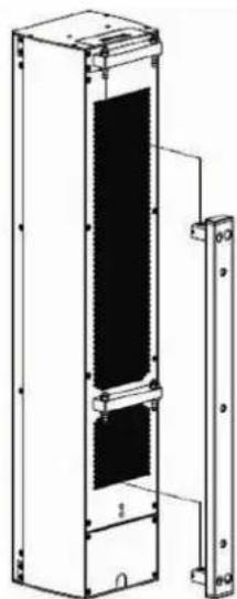
natural_image
Technical line drawing of a vertical panel or enclosure with mounting holes and a side-mounted bracket (no text or symbols)Having the hinge points on either side of the QFlex column allow the loudspeaker to be rotated at 90 degrees to the mounting structure allowing easy access to the input connector panel.
The installer must ensure that the mounting surface is capable of safely and securely supporting the loudspeaker. Seek help from architects, structural engineers or other specialists if in any doubt.
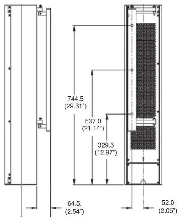
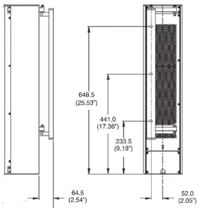
10.2 WALL BRACKET MOUNTING CENTRES - QFLEX 8 & QFLEX 16
QFlex must be wall mounted with the separately ordered mounting kit. The Wall bracket should be fitted to the wall first. When you are satisfied with the mounting locations, fix the bracket to the wall using the instructions supplied with the bracket and ensuring that the installation complies with all local regulations.
QFlex 8
QFlex 16
10.3 QFLEX 24 & QFLEX 32 ASSEMBLY
It is recommended that you assemble the column horizontally on a flat surface. Lay some cloth or cardboard on the surface to avoid scratching the surface of the product during the assembly process.
In the hardware pack you will find one wall bracket and joining hardware consisting of one heavy joining plate with hinge points, two small link bars and M4 Phillips screws.
Place each module in its respective position on the assembly area keeping them slightly spaced apart. Take the flying RJ45 connector in the lower module and insert it into the RJ45 socket in the upper module. Take the flying AC mains connector in the lower module and insert it into the female connector in the upper module.
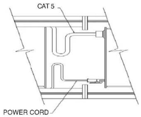
Align the two columns together as shown below.
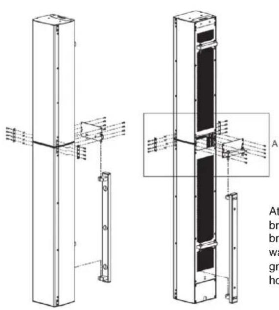
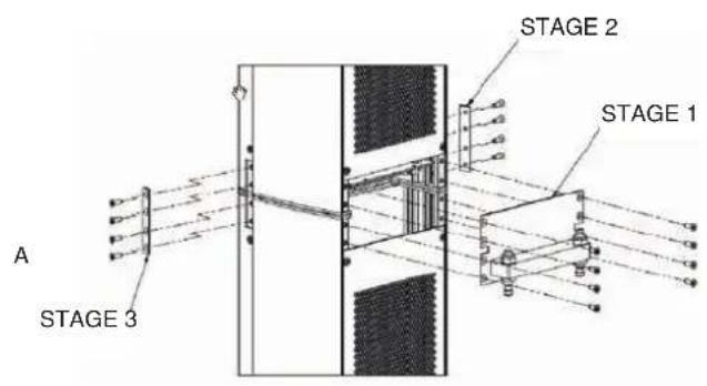
Attach the joining plates in the three stages as shown. Only one wall bracket it required to mount the two modules. For flexibility the wall bracket can be mounted to either the top or the bottom column. The wall bracket can be hinged on the left or right pivot points. 3mm Allen grub screws allow the QFlex to be locked at the desired horizontal angle.
Having the hinge points on either side of the QFlex column allow the loudspeaker to be rotated at 90 degrees to the mounting structure allowing easy access to the input connector panel.
The installer must ensure that the mounting surface is capable of safely and securely supporting the loudspeaker. Seek help from architects, structural engineers or other specialists if in any doubt.
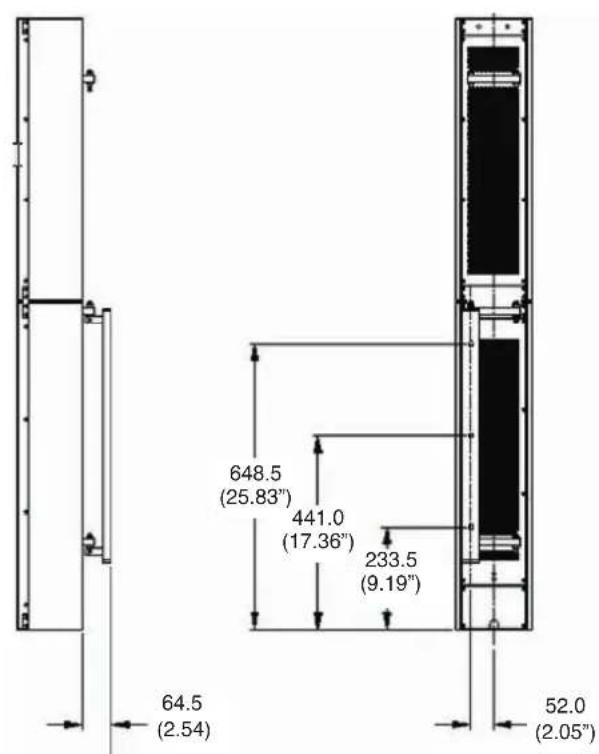
10.4 WALL BRACKET MOUNTING CENTRES - QFLEX 24 & QFLEX 32
QFlex must be wall mounted with the separately ordered mounting kit. The Wall bracket should be fitted to the wall first. When you are satisfied with the mounting locations, fix the bracket to the wall using the instructions supplied with the bracket and ensuring that the installation complies with all local regulations.
QFlex 24

QFlex 32
10.5 QFLEX 40 ASSEMBLY
It is recommended that you assemble the column horizontally on a flat surface. Lay some cloth or cardboard on the surface to avoid scratching the surface of the product during the assembly process.
In the hardware pack you will find two wall brackets and joining hardware consisting of two heavy joining plates with hinge points, four small link bars and M4 Phillips screws.
Place each module in its respective position on the assembly area keeping them slightly spaced apart. Take the flying RJ45 connector in the lower module and insert it into the RJ45 socket in the middle module. Take the flying AC mains connector in the lower module and insert it into the female connector in the middle module. Take the flying RJ45 connector in the middle module and insert it into the RJ45 socket in the top module. Take the flying AC mains connector in the middle module and insert it into the female connector in the top module.

Align the three columns together as shown below.

natural_image
Technical line drawing of a vertical structural assembly with mounting brackets and internal components (no text or symbols)
Attach the joining plates between each module in the three stages as shown.
The wall brackets can be hinged on the left or right pivot points. 3mm Allen grub screws allow the QFlex 40 to be locked at the desired horizontal angle.
Having the hinge points on either side of the QFlex column allow the loudspeaker to be rotated at 90 degrees to the mounting structure allowing easy access to the input connector panel.
The installer must ensure that the mounting surface is capable of safely and securely supporting the loudspeaker. Seek help from architects, structural engineers or other specialists if in any doubt.
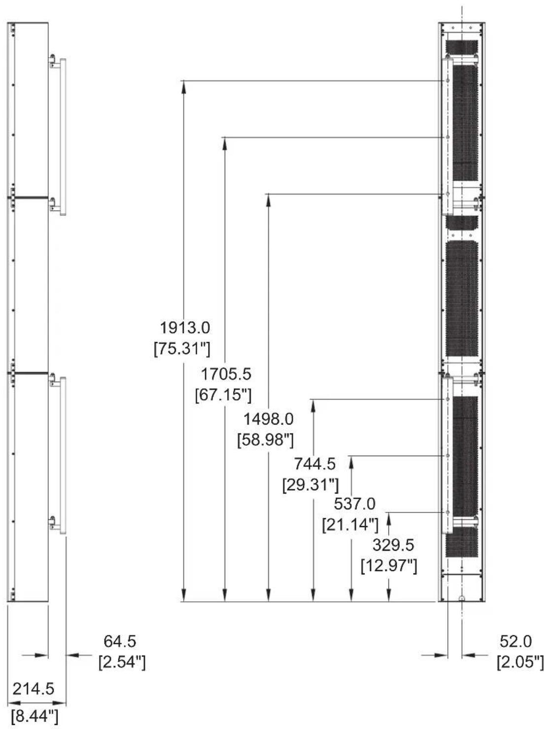
10.6 WALL BRACKET MOUNTING CENTRES - QFLEX 40
QFlex must be wall mounted with the separately ordered mounting kit. The Wall bracket should be fitted to the wall first. When you are satisfied with the mounting locations, fix the bracket to the wall using the instructions supplied with the bracket and ensuring that the installation complies with all local regulations.
other
| Dimension | Value | | --------- | --------- | | Width | 214.5 | | Height | 8.44 | | Width | 64.5 | | Height | 2.54 | | Width | 1913.0 | | Height | 75.31 | | Width | 1705.5 | | Height | 67.15 | | Width | 1498.0 | | Height | 58.98 | | Width | 744.5 | | Height | 29.31 | | Width | 537.0 | | Height | 21.14 | | Width | 329.5 | | Height | 12.97 | | Width | 52.0 | | Height | 2.05 |10.7 QFLEX 48 ASSEMBLY
It is recommended that you assemble the column horizontally on a flat surface. Lay some cloth or cardboard on the surface to avoid scratching the surface of the product during the assembly process.
In the hardware pack you will find two wall brackets and joining hardware consisting of two heavy joining plates with hinge points, one heavy joining plate, six small link bars and M4 Phillips screws.
Place each module in its respective position on the assembly area keeping them slightly spaced apart. Take the flying RJ45 connector in the first (bottom) module and insert it into the RJ45 socket in the second module. Take the flying AC mains connector in the first (bottom) module and insert it into the female connector in the second module. Take the flying RJ45 connector in the second module and insert it into the RJ45 socket in the third module. Take the flying AC mains connector in the second module and insert it into the female connector in the third module. Take the flying RJ45 connector in the third module and insert it into the RJ45 socket in the fourth (top) module. Take the flying AC mains connector in the third module and insert it into the female connector in the fourth (top) module.
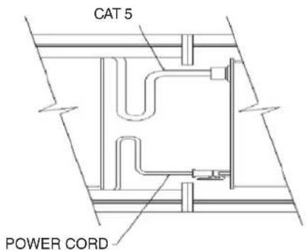
Align the four columns together as shown below.

The wall brackets can be hinged on the left or right pivot points. 3mm Allen grub screws allow the QFlex 40 to be locked at the desired horizontal angle. The installer must ensure that the mounting surface is capable of safely and securely supporting the loudspeaker. Seek help from architects, structural engineers or other specialists if in any doubt.
10.8 WALL BRACKET MOUNTING CENTRES - QFLEX 48
QFlex must be wall mounted with the separately ordered mounting kit. The Wall bracket should be fitted to the wall first. When you are satisfied with the mounting locations, fix the bracket to the wall using the instructions supplied with the bracket and ensuring that the installation complies with all local regulations.

other
| Dimension | Value | | --------- | ------- | | Height | 1913.0 | | Width | 75.31 | | Height | 1705.5 | | Width | 67.15 | | Height | 1498.0 | | Width | 58.98 | | Height | 744.5 | | Width | 29.31 | | Height | 537.0 | | Width | 21.14 | | Height | 329.5 | | Width | 12.97 | | Height | 52.0 | | Width | 2.05 | | Height | 64.5 | | Width | 2.54 | | Height | 214.5 | | Width | 8.44 |11 SYSTEM CONNECTIVITY
NOTE, QFlex is a professional product intended for installation by properly qualified and certificated personnel.
Cable Management
All connections (AC, Network, and Signal) are accessed at the bottom of the QFlex column. This allows for neat, unobtrusive cable management in your installation. The connectors will not be visible when installation is complete. Connections are accessed by the removal of the lower rear access plate on a QFlex master which will require the use of a Philips screwdriver.

natural_image
3D technical illustration of an electrical enclosure with internal components and a pipe fitting (no text or symbols)With the plate removed the connector areas look like this
END VIEW
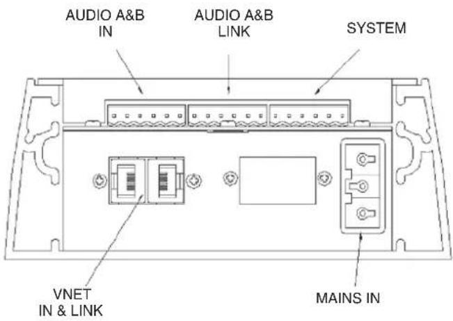
TOP VIEW
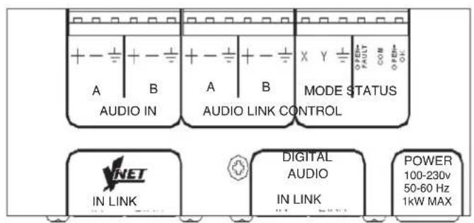
12 AUDIO CONNECTIONS
The signal input & link connectors are fully balanced.
When connecting a balanced signal be sure to wire to the following standard:-
Hot (+), Cold (-), Shield (GND)
In a standard balanced interconnection there are two signal conductors and a shield. The shield is normally referenced to ground at one or both ends. Many times the shield is lifted at one end, usually at the input to eliminate "ground loops" or noise. The problem with this approach is that while it may reduce hum, the shields act as radio antennas and pickup radio frequency interference from the environment.
Multiple enclosures may be driven from a single audio source; simply connect the signal source output into the first input socket, and patch that speakers link to the next speakers input & so on.
13 NETWORK CONNECTIONS (VNET in & Link)
Interconnection between the network computer and the speakers is very straight forward, using twisted pair cable and simple connectors. The USB to VNET (RS485) interface operates on a shared bus so that a single computer can control any QFlex loudspeaker on the bus, and the computer may gather status information from any device on the bus. Each module contains a unique address so that no user input will be required to configure network nodes.
It is only data that is carried over the network to control setup functions & ongoing system diagnostics, therefore if a network fault occurs, audio can still be delivered. This alleviates the problem of total system failure through a single system controller going down. As each loudspeaker controls it own DSP functions any unforeseen failure would be isolated to only that particular node.
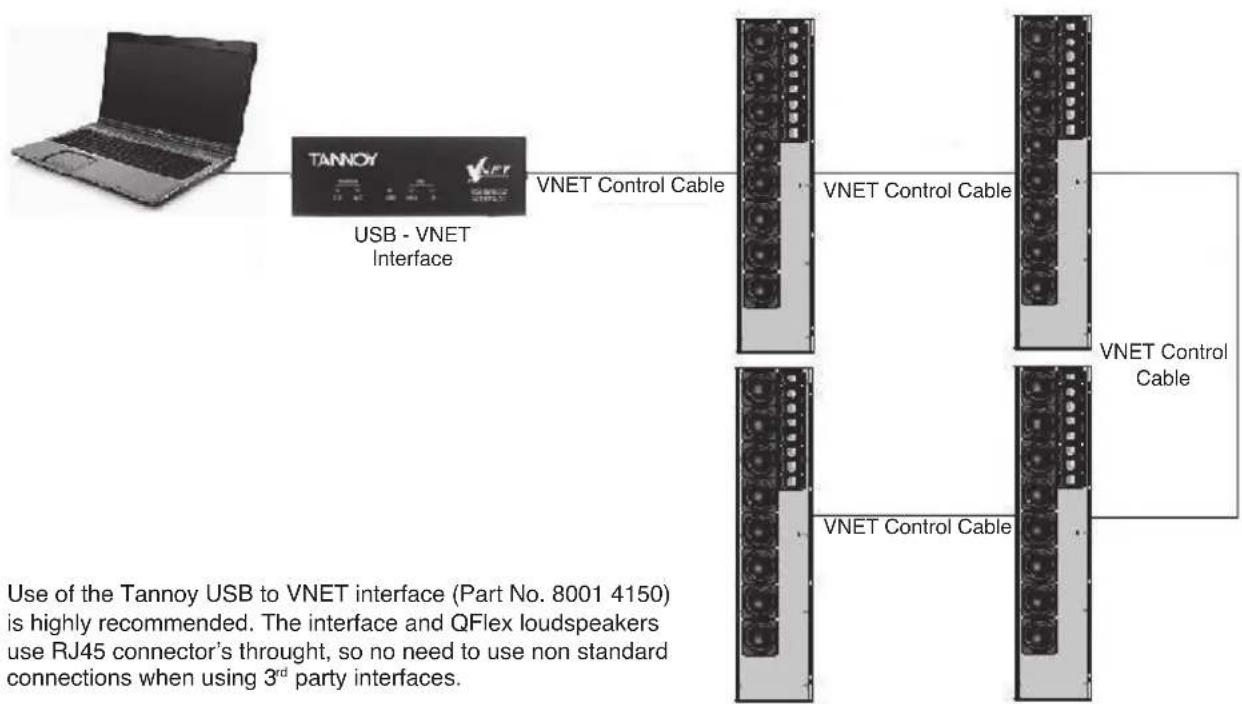
flowchart
graph LR
    A["Laptop"] --> B["TANNOY USB - VNET Interface"]
    B --> C["VNET Control Cable"]
    C --> D["Server 1"]
    C --> E["Server 2"]
    C --> F["Server 3"]
    D --> G["VNET Control Cable"]
    E --> H["VNET Control Cable"]
    F --> I["VNET Control Cable"]
    style A fill:#f9f,stroke:#333
    style B fill:#ccf,stroke:#333
    style C fill:#cfc,stroke:#333
    style D fill:#fcc,stroke:#333
    style E fill:#fcc,stroke:#333
    style F fill:#fcc,stroke:#333
    style G fill:#fff,stroke:#333
    style H fill:#fff,stroke:#333
    style I fill:#fff,stroke:#333
Use of the Tannoy USB to VNET interface (Part No. 8001 4150) is highly recommended. The interface and QFlex loudspeakers use RJ45 connector's through, so no need to use non standard connections when using 3^rd party interfaces.
The VNET network uses the RS-485 protocol for sending serial data. It uses a pair of wires to send a differential signal over distances up to 4000 feet (1200m) without a repeater. The differential signal makes it very robust, RS-485 is one of the most popular communications methods used in industrial applications where its noise immunity and long-distance capability are a perfect fit.
IMPORTANT: Always run a signal ground with RS-485
Connections from the USB to VNET device to the QFlex speaker is as follows:-
| From USB – VNET Interface (or third party interface) | Device RJ45 To VNET Network |
| B+ Pin 1 | |
| A- Pin 2 | |
| GND Pin 5 |
Network connections between nodes are via rugged Neutrik ethercon connectors; these are high quality and are compatible with standard RJ45 plugs. Node connections are made using standard RJ45 connectors and CAT5 cable. Long runs should be solid core, but standard is fine. The implication is that stranded is more robust and less prone to breakage, it is therefore suggested that solid should be used for install applications while stranded is better suited to rental applications. Cabinets can be daisy chained or linked in a star configuration, or a combination of both. Quality termination of all connectors at each node is essential for the network to function correctly.
Linking QFlex Cabinets -
The table below shows the standard straight-through convention for CAT5 patch cables (clip down). These can be used between network nodes. Bear in mind though that only Pins 1, 2, & 5 are used to link the network together.
| Pin 1 (pin No.) | Pin 2 (pin No.) Colour | |
| 1 1 White/Orange | ||
| 2 2 Orange | ||
| 3 3 White/Green | ||
| 4 4 Blue | ||
| 5 5 White/Blue | ||
| 6 6 Green | ||
| 7 7 | White/Brown | |
| 8 8 | Brown | |
To aid the construction of very large networks each speaker provides a source of power (+12Volts) on the network Link connector that can be used to seamlessly power network extenders or repeaters that large networks may require. This power can be located on pin 4 on the NETWORK LINK connector. This power is passed between the NETWORK IN & NETWORK LINK connectors if the speaker is powered off to ensure that upstream VNET powered devices continue to receive power.
14 MAINS POWER
The QFlex unit comes supplied with the mains input connector. It can be located in the mains input socket under the lower connector plate on the rear of the master unit. Additional mains inlet connectors are available from Tannoy, part number 3431-1150.
Use flexible three core mains cables rated to SJ, SJT, or SJE, with 10A minimum capacity and marked VW-1 between the QFlex and fixed wiring point.
Wire the mains input connector as shown below noting the use of the cable gland
(L)ive / Hot = Brown or Black
(N)eutral / Cold = Blue or white
(E)arth / Ground = Green or Green & Yellow

QFlex is suitable for use with mains supplies with nominal voltages and frequencies in the range 100V – 240V and 50Hz/60Hz.
Each Qlex module will limit it's mains inrush current to a worst case of 10A on 230V mains & 5A on 115V mains
QFlex is designed and intended for use in non-domestic situations. Mains power is to be supplied from a permanent hard wired feed. The feed for each QFlex must be protected by a fuse or circuit breaker rated at no more than 10A. It must be possible to isolate the feed to each QFlex by means of a double pole switch with a minimum of 3mm contact separation. All wiring is to comply with local regulations.
Ensure that the QFlex is isolated from the mains supply by means of the above switch before any maintenance or cleaning is undertaken.
The maximum power requirements for QFlex models are as follows :
| Model Max Power req. |
| QFlex 8 220 watts |
| QFlex 16 280 watts |
| QFlex 24 500 watts |
| QFlex 32 560 watts |
| QFlex 40 780 watts |
| QFlex 48 1000 watts |
BROWNOUT will be indicated to the DSP if the mains supply voltage drops below a level where performance will be impaired. Normal operation will automatically resume when the mains recovers.
15 CONTROL INPUTS (SYSTEM INTEGRITY & EMERGENCY PROVISION)
Status control
The system will indicate that it is powered up and working correctly by pulling in a single pole two way relay.
If a fault is detected in either the master unit or any slave units the FAULT relay will be de-energized.
This standard feature allows the means of triggering an external remotely located alarm/indicator (not supplied).
The relay contacts will be rated to carry 500mA at 50VDC.
All three relay contacts are on the Phoenix connector (shown above)
The relay contacts are ‘volt free’, i.e. there is no electrical connection between any of the relay contacts and the QFlex electronics.
Mode control
It will be possible to make the system change its operating mode in the event of an emergency. For example, switch to a different audio input with different EQ.
The operating mode change can be activated by either of two means:
a. an input line (line X) on the master unit being grounded or released (by an external switch, relay or open collector output etc).
b. an input line (line Y) on the master unit detecting the presence or absence of an externally applied voltage greater than +4.5V.
The operating mode change connections are on the Phoenix connector (shown above)
Two Operating Modes (presets) are available – Operating Mode 1 and Operating Mode 2. These allow differences in input processing and input selection to be programmed, and selected by means of the Operating Mode control inputs.
Since input selection and input mixing may be automatically adjusted using Operating Modes, this may be useful for emergency evacuation (Voice Alarm) purposes for example. The Operating Mode thus triggered for VA could select the B input and may have different equalization and gain to the normal Operating Mode.
Since there are two different ways of selecting the Operating Mode using the Operating Mode control inputs, the particular Operating Mode used for VA could be either Operating Mode 1 or Operating Mode 2 depending on the way the system is used.
Although Operating Mode selection is only applied to Master units, the effect will be on all members of the QFlex column since input selection and input processing is for the entire column.
Setting up each operating mode is carried out within the VNET software package (Podware). Instructions can be found in the VNET Software operation section of this user manual.
16 INDICATORS
There is a dim green LED on the back of each QFlex master unit (master) that will illuminate if the PSU is running. All modules within a QFlex product have a blue 'LOCATE' LED visible from the front of the unit, operating as follows:
a. it will illuminate for a few seconds when power is applied and the system initialises
b. it will stay illuminated if the system fails to initialise
c. it will flash for a few seconds if the LOCATE (wink) button for that speaker is pressed on the PodWare control panel
d. It will flash continuously if any fault that causes the FAULT relay to be dropped is detected.
17 SERVICE PARTS
Driver Kit - Type 0803 (3" driver) - 7900 1075
Driver Kit - Type 1004 (4" driver) - 7900 1076
Tweeter Array - 7900 1077
Amplifier Master 8 Way - 7900 1078
Amplifier Master 16 Way - 7900 1079
Amplifier Slave 8 Way - 7900 1080
Amplifier Slave 16 Way - 7900 1081
Grille 8 Way - 7900 1082
Grille Mater 16 Way - 7900 1083
Grille Slave 16 Way - 7900 1087
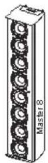
QFlex8
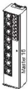
QFlex 16

QFlex×24

QFlex 32

QFlex 40

QFlex 48
QFlex 8 QFlex 16 QFlex 24
Configuration
| 4” LF | 8 | 8 |
| 3” LF | 8 | 8 |
| 1” HF | 8 | 8 |
No. of Amp Channels
100W(RMS) @ 4 Ohms 8 16
24
| Vertical Dispersion | Variable between 10 - 100 degrees (Asymmetric & multiple beams may also be generated) | ||
| Frequency Range | 110Hz - 4kHz | 130Hz - 20kHz | 110Hz - 20kHz |
| Horizontal Dispersion | 120 degrees | 120 degrees | 120 degrees |
| Aiming Angle Limit | +/- 70 degrees | +/- 70 degrees | +/- 70 degrees |
| LF Beam Control Limit | 700Hz | 700Hz | 400Hz |
| Maximum SPL @ 100ft (30m)* | 92dB | 94dB96dB | |
| Column Height | 840mm (33") | 744mm (29.3") | 1483mm (58.4") |
| Column Width | 171.5mm (6.7") | 171.5mm (6.7") | 171.5mm (6.7") |
| Column Depth | 150mm (5.9") | 150mm (5.9") | 150mm (5.9") |
| Typical Application Distance** | 20m (66ft.) | 25m (82ft.) | 40m (131ft.) |
| Sample Rate | 96kHz 96kHz | 96kHz | |
| Audio Inputs | Analogue & AES/EBU | Analogue & AES/EBU | Analogue & AES/EBU |
| Weight inc hardware | 15.25kg (33.6 lbs) | 14.25kg (31.4 bs) | 26.25kg (58.4 lbs) |
18 SPECIFICATIONS (CONTINUED)
QFlex 32 QFlex 40 QFlex 48
Configuration
4" LF 8 16
3" LF 16 16 16
1" HF 16 16 16
No. of Amp Channels
100W(RMS) @ 4 Ohms 32 40 48
| Vertical Dispersion | Variable between 10 - 100 degrees (Asymmetric & multiple beams may also be generated) | ||
| Frequency Range | 130Hz - 20kHz | 110Hz - 20kHz | 110Hz - 20kHz |
| Horizontal Dispersion | 120 degrees | 120 degrees | 120 degrees |
| Aiming Angle Limit | +/- 70 degrees | +/- 70 degrees | +/- 70 degrees |
| LF Beam Control Limit | 400Hz | 250Hz | 200Hz |
| Maximum SPL @ 100ft (30m)* | 100dB | 100dB | 101.5dB |
| Column Height | 1387mm (54.6") | 2127mm (83.75") | 2967mm (116.8") |
| Column Width | 171.5mm (6.7") | 171.5mm (6.7") | 171.5mm (6.7") |
| Column Depth | 150mm (5.9") | 150mm (5.9") | 150mm (5.9") |
| Typical Application Distance** | 50m (165ft.) | 70m (231ft.) | 80m (263ft.) |
| Sample Rate | 96kHz 96kHz | 96kHz | |
| Audio Inputs | Analogue & AES/EBU | Analogue & AES/EBU | Analogue & AES/EBU |
| Weight inc hardware | 25.25kg (55.7 lbs) | 38.5kg (84.9 lbs) | 51.5kg (113.6 lbs) |
19 WARRANTY
No maintenance of the QFlex loudspeakers is necessary.
As part of the MUSIC Group, Tannoy is committed to providing the highest quality products, service and user experience for our customers. One element of this commitment is our after sales support which now incorporates our extended Limited Warranty. In the event of any concern that is not addressed by this extended Limited Warranty we would ask you to contact us at care@music-group.com
For full warranty details including the extended Limited Warranty, please visit http://www.music-group.com/warranty.aspx and register your purchase online at www.music-group.com or www.tannoy.com
t a n noy.com


- CAUTION
- ATTENTION
- CET EQUIPEMENT DOIT ETRE RELIE A LA TERRE
- AVERTISSEMENT DE SECURITE
- IMPORTANT SAFETY INSTRUCTIONS
- INSTALLATION INSTRUCTIONS
- IMPORTANTES INSTRUCTIONS RELATIVES A LA SECURITE
- FOR CUSTOMERS IN THE USA & CANADA
- INTRODUCTION
- UNPACKING
- SOFTWARE INSTALLATION & SETUP
- BEAMENGINE PROGRAMME
- MATLAB RUNTIME LIBRARY MCR
- QFLEX BEAMENGINE APPLICATION
- UNINSTALLING
- UPDATES
- INSTALLING THE MATLAB RUNTIME LIBRARY
- INSTALLING THE BEAMENGINE APPLICATION
- USING BEAMENGINE
- MENU (File, Edit, Processing, Options, Help)
- File
- Edit
- Processing
- Options
- Optimizer Tab
- Default Property
- The Master Beta function
- Fill Holes
- Units Tab
- Misc Tab
- Help
- LAYING OUT VENUE PLANES
- Other Options here are
- OPTIMIZE RESULTS
- ADDING ADDITIONAL VENUE ITEMS
- PROBES
- SAVING STEERING FILE
- BALLOON DATA
- EASE™ and CATT Acoustic™
- BEAMENGINE - FREQUENTLY ASKED QUESTIONS
- SOME DESIGN TIPS
- INSTALLING VNET SOFTWARE (PODWARE)
- USING VNET SOFTWARE (PODWARE)
- OVERVIEW
- LAYOUT
- MENUS
- Preferences
- Network
- Device
- Panel
- TOOLBAR
- The toolbar provides the following one-click functions:
- Open
- Save
- Online
- Locate
- Mute All
- Launch All Panels
- COMMUNICATIONS
- Going Online
- LAUNCHING A PANEL
- CONTROLLING DEVICES – A QUICK OVERVIEW
- PARAMETER SYNCHRONISATION
- PROGRESS BAR
- NAVIGATION
- THE SELECTED DEVICE
- DEVICE CONTEXT MENU
- CONTROL PANELS
- Main Control Panel
- Power Save
- LOADING STEERING DATA
- MONICONS
- CONTROLS
- Drop-Down Selector boxes
- Spin boxes
- Buttons
- Radio buttons
- Faders
- FILTER RESPONSE PANELS
- Copy Graphics
- Copy/Paste Settings
- SAVING & RECALLING DATA
- LOADING FACTORY SETTINGS
- CLONING A DEVICE
- OPERATING MODE
- Protection
- Indication
- DEVICE PROPERTIES
- DEVICE FIRMWARE
- KEYBOARD SHORTCUTS
- In value boxes:
- On Drop-down, Spin, Push, Fader and radio controls:
- On push-button controls:
- On Filter Response Panels:
- HARDWARE CONFIGURATION (GENERL INFORMATION)
- ASSEMBLY INSTRUCTIONS
- QFLEX 8 & QFLEX 16 ASSEMBLY
- WALL BRACKET MOUNTING CENTRES - QFLEX 8 & QFLEX 16
- QFLEX 24 & QFLEX 32 ASSEMBLY
- WALL BRACKET MOUNTING CENTRES - QFLEX 24 & QFLEX 32
- QFLEX 40 ASSEMBLY
- WALL BRACKET MOUNTING CENTRES - QFLEX 40
- QFLEX 48 ASSEMBLY
- WALL BRACKET MOUNTING CENTRES - QFLEX 48
- SYSTEM CONNECTIVITY
- Cable Management
- AUDIO CONNECTIONS
- NETWORK CONNECTIONS (VNET in & Link)
- Linking QFlex Cabinets -
- MAINS POWER
- CONTROL INPUTS (SYSTEM INTEGRITY & EMERGENCY PROVISION)
- Status control
- Mode control
- INDICATORS
- SERVICE PARTS
- SPECIFICATIONS (CONTINUED)
- QFlex 32 QFlex 40 QFlex 48
- Configuration
- WARRANTY
Brand : TANNOY
Model : QFlex 48-WP
Category : Loudspeaker