
HCF 82 - Thermostat HONEYWELL - Free user manual and instructions
Find the device manual for free HCF 82 HONEYWELL in PDF.
| Product Type | Room temperature sensor (without control) |
| Brand and model | Honeywell HCF 82 |
| Power supply | 2 LR06 (AA) 1.5 V batteries (batteries included) |
| Transmission frequency | 868.3 MHz |
| Main functions | Room temperature measurement, radio transmission, frost protection, recognition with zone controller or Hometronic Manager |
| Low battery indicator | Flashing red LED |
| Minimum installation distance | 1 m from metal objects and radio devices (DECT, etc.) |
| Maintenance | Change batteries when the red LED flashes; always replace both batteries at the same time |
| Cleaning | Clean with a soft, dry cloth |
| Safety | Compliant with WEEE directive (2002/96/EC); do not dispose of with household waste |
| Spare parts | Not available (not mentioned) |
| Warranty | Not specified |
Frequently Asked Questions - HCF 82 HONEYWELL
User questions about HCF 82 HONEYWELL
0 question about this device. Answer the ones you know or ask your own.
Ask a new question about this device
Download the instructions for your Thermostat in PDF format for free! Find your manual HCF 82 - HONEYWELL and take your electronic device back in hand. On this page are published all the documents necessary for the use of your device. HCF 82 by HONEYWELL.
USER MANUAL HCF 82 HONEYWELL
Setpoint Adjuster HCW 82/ Room Temperature Sensor HCF 82
Installation and Operation
- Overview 7
1.1. Application 7
1.2. Differences HCW 82/HCF 82 7
1.3. Scope of delivery 7 - Commissioning 7
2.1. Teach-in 8
2.1.1. Assignment to underfloor heating controller 8
2.1.2. Assignment to Hometronic Manager HCM 200D...8
2.1.3. Assigning an HCF 82 for frost protection function
2.1.4. Failed teach-in 8
2.2. Installation 8 - Particular features of HCW 82. 9
3.1. Operation 9
3.2. Limiting the adjustment range 9
3.3. Operation with an external power source 9
3.4. Installing the window contact 10 - Changing batteries 10
- Checking radio transmission 10
- Help with problems 10
- Technical data 10
- WEEE directive 2002/96/ EC - Waste Electrical and Electronic Equipment directive 10
1. Overview
The HCW 82/HCF 82 room devices are used for intelligent room temperature control. The room temperature sensor HCF 82 measures the room temperature and sends the measured values to other devices.
The HCW 82 measures the room temperature and additionally allows the room setpoint temperature to be adjusted.
1.1. Application
The room devices transfer the data with 868.3 MHz. The data can be received by other devices such as the underfloor heating controller HCE 80/HCC 80/HCE 80R/HCC 80R or the Hometronic Manager HCM 200D.
Thus a large spectrum of applications can be covered from individual room control to frost protection control.
1.2. Differences HCW 82/HCF 82
The HCF 82:
- Connection possibility for an external power supply unit (see "Operation with an external power source", Page 9).
- Connection possibility for a window contact (see "Installing the window contact", Page 10).
- Adjustment dial at which you can change the room temperature setpoint directly.
The adjustment range amounts to ± 12^ , starting from the basic value of 20^ (in position 0).
1.3. Scope of delivery
1 HCW 82/HCF 82
2 AA batteries
2. Commissioning
WARNING

Insufficient data transfer!
Interference of the radio receiver in the device through metallic objects or further radio devices.
Ensure there is sufficient distance to metallic objects.
Mount the device with a distance of at least 1 m to radio devices such as radio headphones, cordless phones according to the DECT standard, etc.
- Select another installation site if the radio interference cannot be rectified.
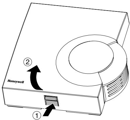
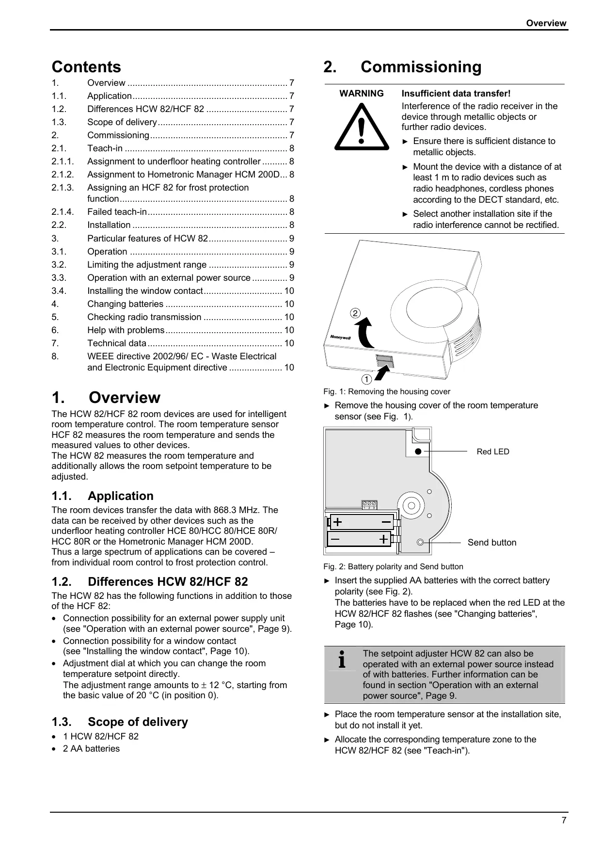
Fig. 1: Removing the housing cover
- Remove the housing cover of the room temperature sensor (see Fig. 1).
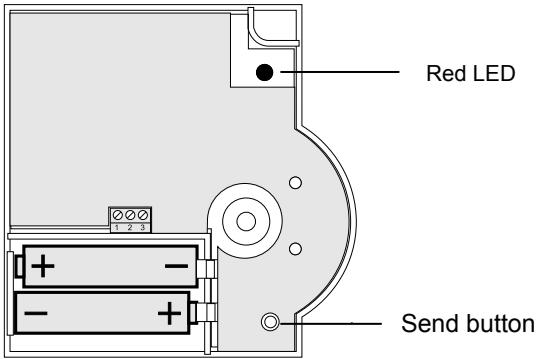
Fig. 2: Battery polarity and Send button
- Insert the supplied AA batteries with the correct battery polarity (see Fig. 2). The batteries have to be replaced when the red LED at the HCW 82/HCF 82 flashes (see "Changing batteries", Page 10).
i
The setpoint adjuster HCW 82 can also be operated with an external power source instead of with batteries. Further information can be found in section "Operation with an external power source", Page 9.
- Place the room temperature sensor at the installation site, but do not install it yet.
- Allocate the corresponding temperature zone to the HCW 82/HCF 82 (see "Teach-in").
2.1. Teach-in
2.1.1. Assignment to underfloor heating controller
In order to assign a temperature zone to the HCW 82/ HCF 82, follow the instructions from the chapter entitled "Start-up" in the "Underfloor heating controller HCE 80/HCE 80R/ HCC 80/HCC 80R" installation instructions.
2.1.2. Assignment to Hometronic Manager HCM 200D
In order to assign a temperature zone to the HCW 82/ HCF 82, follow the instructions from the chapter entitled "Installing the HCW 82/HCF 82 and assigning it to a room" in the Hometronic Manager HCM 200D operating instructions.
2.1.3. Assigning an HCF 82 for frost protection function

The HCW 82/HCF 82 can only be assigned to the Hometronic Manager as a frost protection sensor if the device switch HS 30 is used for the boiler request.
Proceed as follows in order to assign the HCF 82 as a frost protection sensor:
Press the Input but
The Hometronic Manager is in the "Settings" menu.
INSTALLATION
DE-INSTALLATION DAYLIGHTSAVING TIME SENSORFUNCTION
Go to the "Installation" menu.
Go to the "Boiler request" menu.
Turn the Input button until "Frost protec. sensor" is selected.
SWITCHING MODULE
ROST PROTEC.
SENSOR
Press the input button.
The cursor flashes next to the "Frost protec. sensor". The Hometronic Manager is ready to receive data from the sensor.
Activate the teach-in function within 4 minutes by pressing the Send button at the room temperature sensor (see Fig. 2, Send button).
After successful teach-in, a * appears next to "Frost protec. sensor" in the display of the Hometronic Manager: The room temperature sensor is assigned to the Hometronic Manager for the frost protection function.

For information on how to read measured data of the room temperature sensor at the Hometronic Manager or adapt the threshold value for the frost protection function, please refer to the operating instructions of the Hometronic Manager.
2.1.4. Failed teach-in
If the teach-in has failed:
Improve the data transfer (see below).
Repeat the teach-in.
Improving the data transfer
- When selecting the operating site of each device ensure that the distance to radio devices such as radio headphones, cordless phones, etc. according to the DECT standard amounts to at least 1m .
- Do not install the devices over metallic wall connecting sockets and at least 30~cm away from the cover of the heat generator.
- Correct the installation site of the room temperature sensor if necessary.
2.2. Installation
Remove the batteries.
Mark the drill holes according to the drilling template (see Fig. 3).
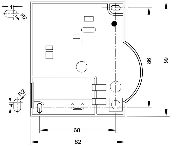
Fig. 3: Drilling scheme (measurements in mm)
Drill the holes.
Screw on the room temperature sensor.
Re-insert the batteries.
- Place the housing cover in position above and snap it down (see Fig. 4).
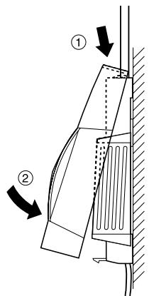
Fig. 4: Placing housing cover in position
3. Particular features of HCW 82
3.1. Operation
The room setpoint temperature can be set easily at the setpoint adjuster HCW 82 by means of an adjustment dial. The adjustment range amounts to ± 12^ , starting from the basic value of 20^ (in position 0).
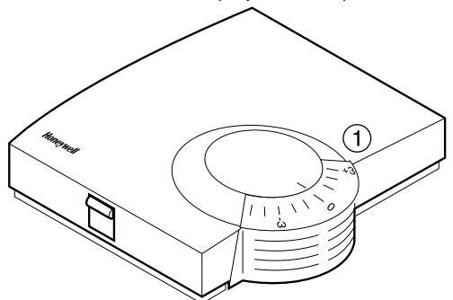
Fig. 5: HCW 82
Select the desired change of the preset temperature at the adjustment dial (1) (see Fig. 5) (settings on the scale in ^ C ).
3.2. Limiting the adjustment range
You can limit the setting range that can be used at the adjustment dial.
Remove the housing cover (see Fig. 1, Page 7).
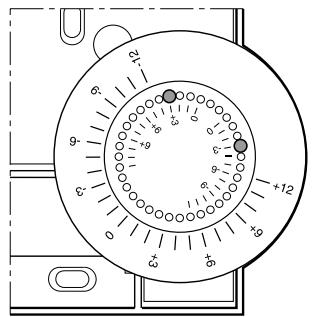
Fig. 6: Limiting the adjustment range
- Place the two small pins into the holes of the adjustment dials in order to limit the adjustment range (see Fig. 6). Orientate yourself on the basis of the inner scale: In Fig. 6, the pins are inserted so that the adjustment dial can only be adjusted by ± 3^ around the zero point.
Turn the adjustment dial clockwise until it stops. - Check whether the adjustment dial is in the position shown in Fig. 5.
If appropriate, put the adjustment back in, rotated by 180^ until it has the position shown.
Turn the adjustment dial to Position 0. - Place the housing cover in position above and snap it down (see Fig. 4).
3.3. Operation with an external power source
In addition to battery operation, the setpoint adjuster HCW 82 is also prepared for operation with an external power source.

WARNING
Damage to the device!
Use of an unsuitable power supply unit.
- Use a power supply unit with 3VDC ± 10% , min. 25mA .
- Keep the power supply unit de-energised while connecting it.
Observe the connection diagram next to the cable terminals.
Have a power supply unit with 3VDC± 10% ,min.25 mA at hand.
De-energise the power supply unit.
Remove the housing cover of the HCW 82 (see Fig. 1, Page 7).
Remove the batteries.
Dispose of the batteries according to the local statutory requirements and not with the used domestic refuse.
Unscrew the setpoint adjuster HCW 82.
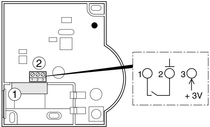
Fig. 7: Connection of the external power source (only HCW 82)
i
The maximum permissible cable length from the power supply unit to the device amounts to 100m . If possible, use a cable of the type JE-Y (ST)Y 2x2x0.8 mm or JE-LIYCY 2x2x0.5 mm².
-
Lead the outlet cable of the power supply unit through the housing opening (1) (see Fig. 7) to the inside.
Connect the outlet cable to the terminal (2) (see Fig. 7). -
Connection 2: Earth
- Connection 3: Voltage
Screw the setpoint adjuster HCW 82 back on.
- Place the housing cover in position above and snap it down (see Fig. 4).
3.4. Installing the window contact
- Connect any sensor with floating contact to the HCW 82 (installation to connection 1 and connection 2, see Fig. 7(2), Page 9).
- Assign the HCW 82 to the Hometronic Manager HCM 200D as a sensor (refer to the HCM 200D instructions "Assigning a room to a sensor").

If several floating contacts are used, these have to be connected in series.
4. Changing batteries
Change the batteries if the red LED of the room temperature sensor flashes and the device is not in test mode.
- Remove the housing cover of the HCW 82/HCF 82 (see Fig. 1).
Remove the batteries.
Dispose of the batteries according to the local statutory requirements and not with the used domestic refuse.

Always replace both batteries together. Only use 1.5V batteries of the type LR06, AA.
- Insert the batteries with the right polarity into the battery compartment (see Fig. 2).
- Place the housing cover on at the top and latch it in downwards (see Fig. 4).
5. Checking radio transmission
The HCW 82/HCF 82 can send a test signal to the allocated receiver (for example an underfloor heating controller) in order to test the signal strength.
- Keep the teach-in button pressed for at least 30 s until the red LED extinguishes.
The device is now in test mode and sends a test signal every 5 seconds.
The LED flashes briefly at every test signal. - Check the radio transmission at the receiver. Refer to the respective instructions for information about receiving and evaluating the test signals.

The test mode is terminated automatically after 5 minutes. The test mode can also be terminated by removing the batteries, disconnecting the power supply or by pressing the teach-in button.
6. Help with problems
| Problem | Cause | Remedy |
| Teach-in failed | Batteries inserted incorrectly | ► Insert the batteries correctly. |
| Radio connection failure | ► Eliminate interference sources (metal, wireless devices).► Correct installation site.► Repeat the teach-in. | |
| No measured data at Hometronic Manager | Batteries inserted incorrectly | ► Insert the batteries correctly. |
| Radio connection failure | ► Eliminate interference sources (metal, wireless devices).► Repeat the teach-in. | |
| Module not assigned or assigned incorrectly | ► Repeat the teach-in.► Check the assignment. If appropriate, repeat. | |
| Window contact is ignored | Window contact not assigned | ► Repeat the teach-in for the window contact. |
7. Technical data
| Batteries | 1.5 V, type LR06, AA |
| Power supply unit | 3 V DC ± 10 %, min. 25 mA |
| Cable for power supply unit/window contact | Ø 2x0.8 mm; 2x0.5 mm² max. length 100 m |
| Frequency | 868.3 MHz (transmitter) |
8. WEEE directive 2002/96/ EC - Waste Electrical and Electronic Equipment directive
At the end of the product life dispose of the packaging and product in a corresponding recycling centre.
Do not dispose of the unit with the usual domestic refuse.
Do not burn the product.
Sommaire
Raccordement 2: masse
Raccordement 3: tension
SWITCHING MODULE
PROST PROTEC.
SENSOR
Manufactured for and on behalf of the Environmental and Combustion Controls Division of Honeywell Technologies Sàrl, Ecublens, Route du Bois 37, Switzerland by its Authorized Representative:
Honeywell GmbH
Böblinger Straße 17
71101 Schonaich, Germany
Tel.: (++49) (0) 703163701
Fax: (+ + 49) (0) 7031637493
http://europe.hbc.honeywell.com
The right is reserved to make
modifications
This document is definitive for the enclosed product and replaces all previous publications.
Honeywell Inc. hereby declares that this device complies with the basic requirements and other relevant regulations of guideline 1999/5/EC. The declaration of conformity of the product can be requested from the manufacturer.
Note to non-EU countries: This product may only be used if operation in the 868 MHz frequency band is permissible.