
Texart RT-640 - Printer ROLAND - Free user manual and instructions
Find the device manual for free Texart RT-640 ROLAND in PDF.


| Product Type | Dye-Sublimation Printer |
| Model | Roland Texart RT-640 |
| Print Technology | Piezo Inkjet (Dye-Sublimation) |
| Maximum Print Width | 64 inches (1625 mm) |
| Maximum Resolution | 1440 x 1440 dpi |
| Media Width | Up to 64 inches (1625 mm) |
| Ink Type | Roland Texart Sublimation Ink |
| Number of Ink Channels | 4 (CMYK) |
| Print Speed (Standard Mode) | Up to 38 m²/h |
| Dimensions (W x D x H) | Approx. 2500 x 700 x 600 mm |
| Weight | Approx. 95 kg |
| Power Requirements | AC 100-240 V, 50/60 Hz, 1.8 A |
| Power Consumption | Operation: 160 W, Standby: 30 W |
| Connectivity | Ethernet (10BASE-T/100BASE-TX), USB 2.0 |
| Operating Environment | Temperature: 20-30°C, Humidity: 35-65% RH |
| Maintenance Functions | Automatic cleaning of print head, wiper blade replacement |
| Safety Features | Emergency stop, media cover interlock, automatic cutter guard |
| Spare Parts & Repairability | Replaceable print head, maintenance cartridge, serviceable rollers |
| General Information | Designed for textile sublimation transfer printing; includes Roland VersaWorks RIP software |
Frequently Asked Questions - Texart RT-640 ROLAND
User questions about Texart RT-640 ROLAND
0 question about this device. Answer the ones you know or ask your own.
Ask a new question about this device
Download the instructions for your Printer in PDF format for free! Find your manual Texart RT-640 - ROLAND and take your electronic device back in hand. On this page are published all the documents necessary for the use of your device. Texart RT-640 by ROLAND.
USER MANUAL Texart RT-640 ROLAND
natural_image
Line drawing of a printer with a paper holder and control panel (no text or symbols)Thank you very much for purchasing this product.
To ensure correct and safe usage with a full understanding of this product's performance, please be sure to read through this manual completely and store it in a safe location.
➢ Unauthorized copying or transferral, in whole or in part, of this manual is prohibited.
The contents of this operation manual and the specifications of this product are subject to change without notice.
The operation manual and the product have been prepared and tested as much as possible. If you find any misprint or error, please inform Roland DG Corp.
➢ Roland DG Corp. assumes no responsibility for any direct or indirect loss or damage which may occur through use of this product, regardless of any failure to perform on the part of this product.
➢ Roland DG Corp. assumes no responsibility for any direct or indirect loss or damage which may occur with respect to any article made using this product.
This product is using GNU General Public License (GPL) / GNU Lesser General Public License (LGPL) software. You have the right to acquire, modify, and distribute the source code for this GPL/LGPL software. You can obtain the GPL/LGPL source code used in this product by downloading it from the following website:
URL: http://www.rolanddg.com/gpl/
RolandDG Corp. has licensed the MMP technology from the TPL Group.
Contents....1
1. Machine Overview ....5
Part Names and Functions....6
This Machine....6
Operation Panel 8
Menu Charts....9
Main Menu....9
Language and Unit Menu....12
Function Menu 12
Important Notes on Handling and Use 13
2. Basic Operation ...... 15
Preparing Media....16
Types of Media 16
Conditions for Usable Media....16
Media Storage Environment 16
Switch On! 17
Switch On! 17
Sleep Mode (Power-saving Feature) 17
Loading Media 18
Loading Roll Media 18
Loading Sheet Media 34
Performing the Initial Adjustment (Correcting for Misalignment in Bidirectional Printing More Precisely)....37
Setup of Media 39
About [Media Setting] menu 39
Setup of Media ([Media Setting] menu)....39
Printing 44
Setting the Printing-start Location 44
Printing Tests and Normal Cleaning 45
Getting Ready to Receive Data from a Computer 47
Starting Printing....48
Remaining Ink during Printing 48
Pausing or Canceling Printing....49
Cutting Off the Media 49
Transfer conditions ....51
Switch Off! 52
Switch Off....52
3. Maintenance: Keeping the Machine in Good Working Order....53
Ink Pouch Replacement....54
Out-of-ink Warnings 54
Ink Pouch Replacement 55
Maintenance that Should Be Performed Daily 57
Disposing of Discharged Fluid....57
Cleaning....59
Care and Maintenance of the Print Heads....60
When Normal Cleaning Is Not Effective....61
Medium/Powerful Cleaning 61
If Colors are Uneven 62
Mixing the Ink by Shaking the Ink Pouch 62
Light Choke Cleaning....62
Maintenance that Should Be Performed More Than Once a Month .....64
When Manual Cleaning Becomes Necessary 64
Manual Cleaning....65
Maintenance that Should Be Performed Every Six Months ....70
Refreshing Subtanks (REFRESH SUBTANK)....70
When Missing Pixels Etc. Cannot be Corrected 73
When Missing Pixels Etc. Cannot be Corrected 73
Replacing Consumable Parts....76
Replacing the Wiper 76
Replacing the Felt Wiper 79
Replacing the Separating Knife....82
When Not in Use for a Prolonged Period 84
Keep Performing Maintenance 84
Alarm Feature 84
If the Machine has not been Used for Over One Month 84
4. Advanced Functions....85
Fully Utilizing the Preset Function 86
Saving Various Settings as a Name Assigned Preset....86
Loading a Saved Preset 87
Fully Utilizing the Correction Function....88
Correcting for Misalignment in Bidirectional Printing 88
Correcting for Misalignment in Bidirectional Printing More Precisely....89
Alleviating Horizontal Bands (Feed Correction Function) 89
Accommodating to the Types and Condition of Media 91
Adjusting Print Head Height to Match Media Thickness 91
Using Transparent Media....92
Using Hard-to-dry Media....94
Using Media that does not Move Smoothly....94
Changing the Range of Print-head Carriage Movement 95
Expanding the Printing Area by Reducing the Margins 96
Preventing Soiling of the Media and Dot Drop-Out....97
Using Sticky Media....98
Printing with Crop Marks 99
Printing with Crop Marks....99
Using the Media Take-up System....100
Using the Media Take-up System 100
5. To Administrators ....101
Printing Operation Management 102
Printing a System Report....102
Determining What Happens When Ink Runs Out (Only When 8 Colors are Selected)
102
Displaying the Amount of Media Remaining.... 103
Making Sure to Verify the Setting for the Amount Remaining Every Time the Media Is
Changed 104
Printing the Amount of Remaining Media 104
System Management of Machine....106
Setting Menu Language and Units of Measurement 106
Setting Activation Interval for Sleep Mode (Power-saving Feature).... 106
Viewing Information about the System of This Machine.... 107
Returning All Settings to Their Factory Default Values....108
Changing Installation Location 109
6. Read this Chapter Whenever you Face a Problem (FAQ).... 111
Attractive Printing is Impossible 112
Printed Results Are Coarse or Contain Horizontal Stripes 112
Colors Are Unstable or Uneven 113
The Media Becomes Soiled When Printed 114
Color Mixing Occurs 114
Media Jam Occurs! 115
The Media has Jammed 115
Media Feed is Not Smooth....116
Media Wrinkles or Shrinks 116
Media Feed Is Not Straight....116
Media Feed Is Not Smooth....117
Why Has the Print-head Carriage Stopped Moving? 118
What to Do First 118
If the Print Heads Still Do Not Move 118
Other Problems 120
The Machine Does Not Move....120
Cannot Cut Off the Media. 121
It is not Possible to Check the Amount of Discharged Fluid in the Drain Bottle ..... 121
A Message Appears 122
An Error Message Appears 123
7. Main Specifications ....127
Printing Area....128
Maximum Printing Area and Margins 128
Maximum Printing Area When Using Crop Marks 129
The Media-cutoff Location During Continuous Printing 129
Locations of the Power Rating and Serial Number Labels....130
Specifications 131
Company names and product names are trademarks or registered trademarks of their respective holders.
http://www.rolanddg.com/
Copyright © 2014 Roland DG Corporation
1.
Machine Overview

Part Names and Functions ....6
This Machine....6
Operation Panel 8
Menu Charts 9
Main Menu 9
Language and Unit Menu....12
Function Menu 12
Important Notes on Handling and Use....13
This Machine
Front

Back

Front Cover Interior/Print Head Area
Media clamps
These keep the media from coming loose and prevent fuzz on the cut edge of the media from touching the print heads.
Pinch roller
These clamp the media when the loading lever is lowered.
Print-head carriage
The print heads are inside this.
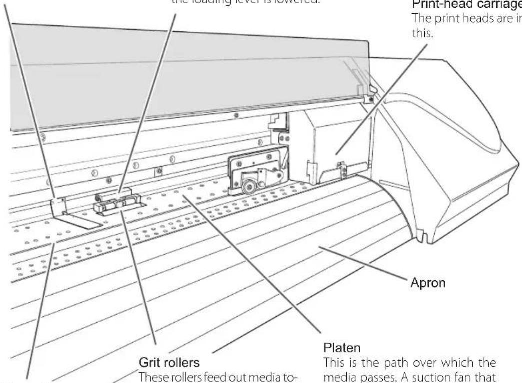
Cutter guide
The separating knife travels along this guide when separating the media.
Grit rollers
These rollers feed out media to-ward the front of the machine.
Platen
This is the path over which the media passes. A suction fan that keeps the media from coming loose is built in.
Operation Panel
Display screen
This displays various setting menus and other information.
BASE POINT light
This lights up when the base point (the print-start position) has been set.
FUNCTION key
You press this when entering the setting menu for cleaning of the print heads, printing tests, and so on.
MENU key
You press this to enter the menus for various settings.
SETUP light
This lights up when media has been loaded correctly.
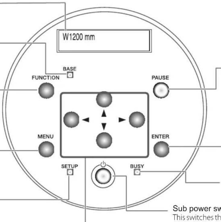
Cursor keys
You use these to select settings for menu items, to move the media, and for other such operations.
PAUSE key
This pauses printing operation. This lights up when operation is paused.
ENTER key
You use this for such tasks as enabling setting values.
BUSY light
This lights up during printing and other such operations.
Sub power switch
This switches the machine on and off. (To switch the machine off, you hold down the switch for one second or longer). The light flashes slowly when the machine is in the sleep mode.
Panel Notation
In this document, the keys and lights on the operation panel are indicated by the following images.
MENU
FUNCTION
ENTER
PAUSE
MENU key
FUNCTION key
ENTER key
PAUSE key
[NO TEXT]
↓
◀
▶
Cursor keys
SETUP
BUSY
BASE
SETUP light
BUSY light
BASE POINT light
Main Menu
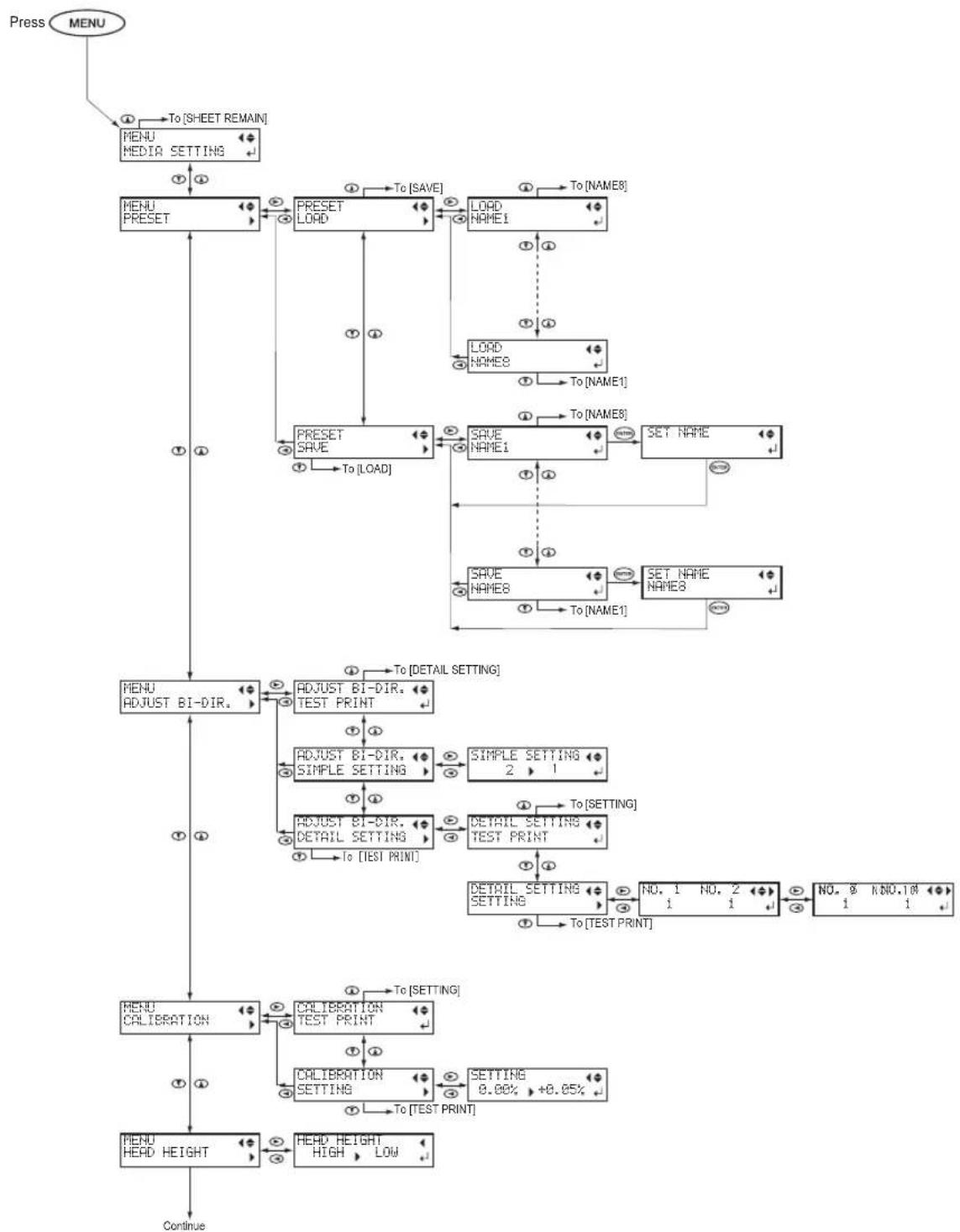
flowchart
graph TD
    A["Press MENU"] --> B["To [SHEET REMAIN"]]
    B --> C["MENU MEDIAT SETTING"]
    C --> D["MENU PRESET"]
    D --> E["PRESET LOAD"]
    E --> F["LOAD NAME1"]
    F --> G["To [NAME8"]]
    G --> H["LOAD NAME8"]
    H --> I["To [NAME1"]]
    I --> J["PRESET SAVE"]
    J --> K["To [LOAD"]]
    K --> L["SAVE NAME1"]
    L --> M["SET NAME"]
    M --> N["SAVE NAME8"]
    N --> O["SET NAME NAME8"]
    O --> P["To [NAME1"]]
    P --> Q["MENU ADJUST BI-DIR."]
    Q --> R["ADJUST BI-DIR. TEST PRINT"]
    R --> S["ADJUST BI-DIR. SIMPLE SETTING"]
    S --> T["SIMPLE SETTING 2 1"]
    T --> U["To [SETTING"]]
    U --> V["DETAIL SETTING TEST PRINT"]
    V --> W["DETAIL SETTING SETTING"]
    W --> X["NO. 1 1 NO. 2 1"]
    X --> Y["NO. 0 1 NO.10 1"]
    Y --> Z["To [TEST PRINT"]]
    Z --> AA["PENU CALIBRATION"]
    AA --> AB["CALIBRATION TEST PRINT"]
    AB --> AC["PENU CALIBRATION"]
    AC --> AD["CALIBRATION SETTING"]
    AD --> AE["SETTING 0.00% +0.05%"]
    AE --> AF["To [TEST PRINT"]]
    AF --> AG["PENU HEAD HEIGHT"]
    AG --> AH["HEAD HEIGHT HIGH LOW"]
    AH --> AI["Continue"]
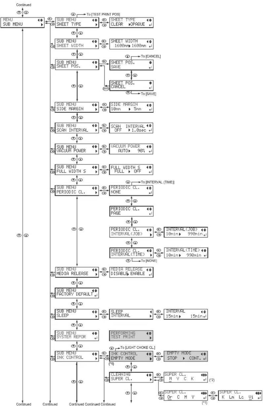
flowchart
graph TD
    A["Continued"] --> B["MENU SUB MENU"]
    B --> C["To [TEST PRINT POS"]]
    C --> D["SHEET TYPE CLEAR OPACHE"]
    D --> E["SHEET WIDTH 1600mm 1600mm"]
    E --> F["SHEET POS. SAVE"]
    F --> G["SHEET POS. CANCEL"]
    G --> H["To [CANCEL"]]
    H --> I["SIDE MARGIN 10mm 5mm"]
    I --> J["SCAN INTERVAL OFF 1.0sec"]
    J --> K["UBAUM POWER AUTO 90%"]
    K --> L["FULL WIDTH S FULL OFF"]
    L --> M["PERIODIC CL. NONE"]
    M --> N["PERIODIC CL. PAGE"]
    N --> O["PERIODIC CL. INTERVAL (JOB) INTERVAL (JOB) 10min 990min"]
    O --> P["INTERVAL (TIME) 10min 990min"]
    P --> Q["INTERVAL (TIME) 10min 990min"]
    Q --> R["PERIODIC CL. INTERVAL (TIME)"]
    R --> S["PERIODIC CL. INTERVAL DEFAULT"]
    S --> T["MEDIA RELEASE DISABLE ENABLE"]
    T --> U["SLEEP INTERVAL INTERVAL 15min 15min"]
    U --> V["INTERVAL 15min 15min"]
    V --> W["PERFORMING TEST PRINT"]
    W --> X["INK CONTROL EMPTY MODE STOP CONT."]
    X --> Y["CLEARING SUPER CL. SUPER CL. M Y C K SUPER CL. Or C M Y SUPER CL. K Lm Lc Ui"]
    Y --> Z["Continued Continued Continued Continued"]
(*1) Displayed when ink type selected is "8COLOR."
(*2) Displayed when ink type selected is "4COLOR."

flowchart
graph TD
    A["Menu SYSTEM INFO."] --> B["SYSTEM INFO. MODEL"]
    B --> C["SYSTEM INFO. SERIAL NO."]
    C --> D["SYSTEM INFO. INK"]
    D --> E["SYSTEM INFO. FIRMWARE"]
    E --> F["SYSTEM INFO. NETWORK"]
    F --> G["SHEET REMAIN PRINT MEMO"]
    G --> H["SHEET REMAIN SET LENGTH"]
    H --> I["SHEET REMAIN AUTO DISPLAY"]
    I --> J["To [MATERIAL SETTING"]]

    K["INK CONTROL LIGHT CHOKE CL."] --> L["INK CONTROL REFRESH SUBTANK"]
    L --> M["To [SUPER CL."] (When using 4 colors)
To["EMPTY MODE"] (When using 8 colors)]
    M --> N["To [DRAIN BOTTLE"]]
    N --> O["To [REPLACE WIPER"]]
    O --> P["To [SHEET TYPE"]]

    Q["MAINTENANCE REPLACE WIPER"] --> R["MAINTENANCE REPLACE FELT"]
    R --> S["MAINTENANCE REPLACE KNIFE"]
    S --> T["MAINTENANCE DRAIN BOTTLE"]
    T --> U["To [REPLACE WIPER"]]
    U --> V["To [SHEET TYPE"]]

    W["TEST PRINT POS SCAN FEED"] --> X["TEST PRINT POS Scan"]

    Y["Network IP ADDRESS"] --> Z["IP ADDRESS 255.255.255.255"]
    Z --> AA["IP ADDRESS 255.255.255.255"]
    AA --> AB["Network SUBNET MASK"]
    AB --> AC["SUBNET MASK 255.255.255.255"]
    AC --> AD["Network GATEWAY ADDR."]
    AD --> AE["GATEWAY ADDR 255.255.255.255"]
    AE --> AF["Network MAC ADDRESS"]
    AF --> AG["MAC ADDRESS xxxxxxxxxxxxxx"]
    AG --> AH["To [IP ADDRESS"]]

    AI["To [NETWORK"]] --> AJ["To [NETWORK"]]

    AK["To [AUTO DISPLAY"]] --> AL["To [AUTO DISPLAY"]]

    AM["To [MATERIAL SETTING"]] --> AN["To [MATERIAL SETTING"]]
Language and Unit Menu

flowchart
graph TD
    A["MENU"] --> B["MENU LANGUAGE ENGLISH"]
    B --> C["LENGTH UNIT mm INCH"]
    C --> D["TEMP. UNIT °C °F"]
    D --> E["ENTER"]
    E --> B
Function Menu

flowchart
graph TD
    A["FUNCTION Press"] --> B["FUNCTION BASE POINT"]
    B --> C["FUNCTION CLEANING"]
    C --> D["CLEANING TEST PRINT"]
    D --> E["CLEANING NORMAL CL."]
    E --> F["CLEANING MEDIUM CL."]
    F --> G["CLEANING POWERFUL CL."]
    G --> H["CLEANING MANUAL CL."]
    H --> I["FUNCTION SHEET CUT"]
    I --> J["To [BASE POINT"] OR_To["CLEANING"]]
    B --> K["To [HEATE R CONFIG"]]
    C --> L["To [MANUAL CL."]]
    D --> M["To [TEST PRINT"]]
    E --> N["To [MANUAL CL."]]
    F --> O["To [MANUAL CL."]]
    G --> P["To [MANUAL CL."]]
    H --> Q["To [TEST PRINT"]]
    I --> R["To [BASE POINT"] OR_To["CLEANING"]]
(*1) This is not displayed when no media is loaded (that is, when is dark) or when the machine is not ready to set the base point. Refer to P. 44"Setting the Printing-start Location" for details.
(*2) This is not displayed when no media is loaded (that is, when SETUP is dark) or when media width is displayed after media loading is complete.
This is not displayed when no media is loaded (that is, when SETUP is dark).
This machine is a precision device. To ensure the full performance of this machine, be sure to observe the following important points. Failure to observe them may not only result in loss of performance, but may also cause malfunction or breakdown.
This Machine
This machine is a precision device.
➢ Never subject the machine to impact or excessive force.
➢ Never needlessly put your hand or fingers inside the cover, the ink-pouch ports, or other internal areas of the machine.
Install in a suitable location.
➢ Install in a location having the specified temperature and relative humidity
➢ Install in a quiet, stable location offering good operating conditions.
The print heads are delicate.
➢ Never needlessly touch or allow media to scrape them.
The print heads may be damaged if allowed to dry out. The machine prevents desiccation automatically, but improper operation may render this feature inoperative. Operate properly, as specified in this manual.
➢ Never allow the machine to stand with an ink pouch removed. Remaining ink in the machine may harden and clog the print heads.
The print heads are components that wear out. Periodic replacement is required, with the frequency of replacement depending on use.
This machine becomes hot.
➢ Never cover the ventilation holes with cloth, tape, or anything else.
Ink pouches
Ink pouches come in various types.
Use a type that is compatible with the machine.
Never subject to impact or attempt to disassemble.
➢ Never drop or shake forcefully. The impact may rupture the internal pouch and cause the ink to leak.
▶ Never attempt to disassemble.
▶ Never attempt to refill the ink.
If ink gets on your hands or clothing, wash it off as soon as possible. Removal may become difficult if you leave such adhered ink untreated.
Storage
Store unopened in a well-ventilated location at a temperature of 5 to 30°C (-4 to 86°F).

Warning Labels
Warning labels are affixed to make areas of danger immediately clear. The meanings of these labels are as follows. Be sure to heed their warnings. Also, never remove the labels or allow them to become obscured.

Caution: Pinching Hazard
Be careful not to allow the fingers to become pinched when closing covers.
Caution: Moving Print Head Carriage
The print head carriage inside the cover move at high speed and pose a hazard. Never insert the hand or fingers into the gap.


WARNING:
HAZARDOUS MOVING PARTS KEEP FINGERS AND OTHER BODY PARTS AWAY.
AVERTISSEMENT:
PIÈCES MOBILES DANGEREUSES. NE PAS APPROCHER LES DOIGTS OU TOUTE AUTRE PARTIE DU CORPS.
Caution: Moving Print Head Carriage
The print head carriage inside the cover move at high speed and pose a hazard. Never insert the hand or fingers into the gap.
Ink, cleaning liquid, and discharged fluid are toxic
If these fluids come into contact with the eyes or skin, it may be hazardous to the health. When performing maintenance work, for example when disposing of discharged fluid, wear protective eyewear and protective gloves (refer to the safety data sheet (SDS)).

2.
Basic Operation
Preparing Media....16
Types of Media....16
Conditions for Usable Media....16
Media Storage Environment.... 16
Switch On!....17
Switch On!....17
Sleep Mode (Power-saving Feature) 17
Loading Media 18
Loading Roll Media 18
Loading Sheet Media 34
Performing the Initial Adjustment (Correcting for Misalignment in Bidirectional
Printing More Precisely)....37
Setup of Media....39
About [Media Setting] menu....39
Setup of Media ([Media Setting] menu).... 39
Printing....44
Setting the Printing-start Location 44
Printing Tests and Normal Cleaning....45
Getting Ready to Receive Data from a Computer.... 47
Starting Printing....48
Remaining Ink during Printing 48
Pausing or Canceling Printing....49
Cutting Off the Media 49
Transfer conditions....51
Switch Off! 52
Switch Off....52
Types of Media
In this manual, the paper used for printing is called "media". There are the following main two media types used in this machine.
➢ Roll media: Media wound onto a paper tube
Sheet media: Media not wound onto a paper tube such as standard-size media
Various paper quality types of roll media and sheet media are selectable according your purpose. For detailed information about each media, contact your media supplier.
Conditions for Usable Media
This machine cannot necessarily print every kind of media. When selecting media, be sure to carry out testing in advance to make sure that satisfactory printing results are obtained.
Size
| Width (*a) | 259 to 1625 mm (10.2 to 64 inches) |
| Maximum media thickness (*a) | 1.0 mm |
| Roll outer diameter | 210 mm |
| Paper tube (core) inner diameter | 76.2 mm (3 inches) or 50.8 mm (2 inches) (*b) |
*a Applies to both roll and sheet media.
*b To use 2-inch media, the optional media flanges are required. For information about optional items, contact your authorized dealer or us.
Maximum roll weight
40 kg (88 lb)
Note: If using the take-up system, this specification depends on the conditions of media that can be used with the take-up system.
Other conditions
Media such as the following cannot be used.
➢ Media whose end is attached to the paper tube (core)
➢ Media which is severely warped or which has a strong tendency to reroll
➢ Media whose paper tube (core) is bent or crushed
➢ Media that bends under its own weight when loaded
▶ Media on a sagging roll
▶ Media that is rolled unevenly
Media Storage Environment
Depending on the type of transfer paper, if it is stored in a humid environment for a long time, the coating of the paper may degrade and affect print quality. (In most cases, once the coating degrades, it will not return to its original condition.) Avoid storing transfer paper in humid environments.
Read the precautions regarding your media carefully, and store it in an appropriate environment. For details, contact your media supplier.
Switch On!
Procedure
1
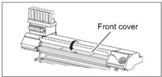
Close the front cover.
2

Switch on the main power.
3
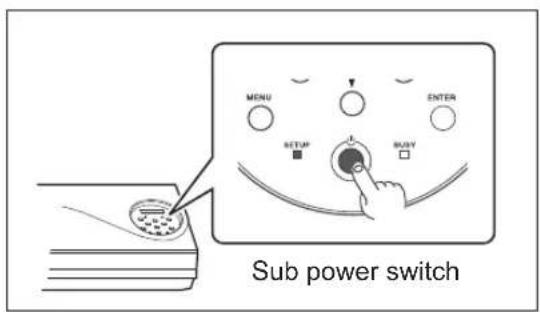
Switch on the sub power.
Sleep Mode (Power-saving Feature)
This machine is provided with a power-saving feature that switches to a low-power "sleep mode" when a fixed interval passes with no operation. The factory default for the time after which the machine switches to the sleep mode is 30 minutes. When the machine is in the sleep mode, the sub power switch flashes slowly. Using the operation panel or sending printing data from the computer restores the machine to its normal mode. This setting of sleep mode can be changed. However, we recommend setting the activation time for the sleep mode to 30 minutes or less to reduce power consumption and prevent problems such as overheating,
P. 106"Setting Activation Interval for Sleep Mode (Power-saving Feature)"
Loading Roll Media
CAUTION
Load roll media correctly.
Otherwise the media may fall and cause injury.
CAUTION
Roll media weighs about 40 kg (88 lb). To avoid injury, handle with care.
CAUTION
Do not load roll media that weighs more than 40 kg (88 lb).
The machine may fail to withstand the weight and tip over or cause the media to fall.
1. Install the media on the media holder.
Note: The media holder of this machine is designed to be used exclusively with media that has a paper tube (core) with an inner diameter of 3 inches. To use 2-inch media, the optional media flanges are required. For information about optional items, contact your authorized dealer or us.
1

Switch off the sub power.
② Open the front cover.
Do not open the front cover until instructed to do so.
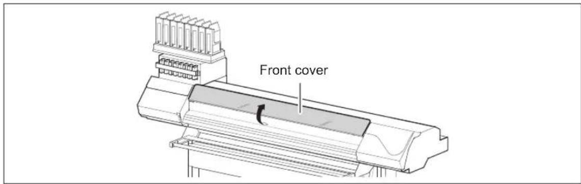

① Loosen the securing screws of media holders.
② Draw the media holders to both left and right ends respectively.


① Fit the paper tube (core) of the media onto the end cap of the media holder (Left).
Do not secure the media holder now.
② Move the media holder (Right) and fit the end cap onto the paper tube (core) of the media.
Fit it securely to prevent the media from moving easily.
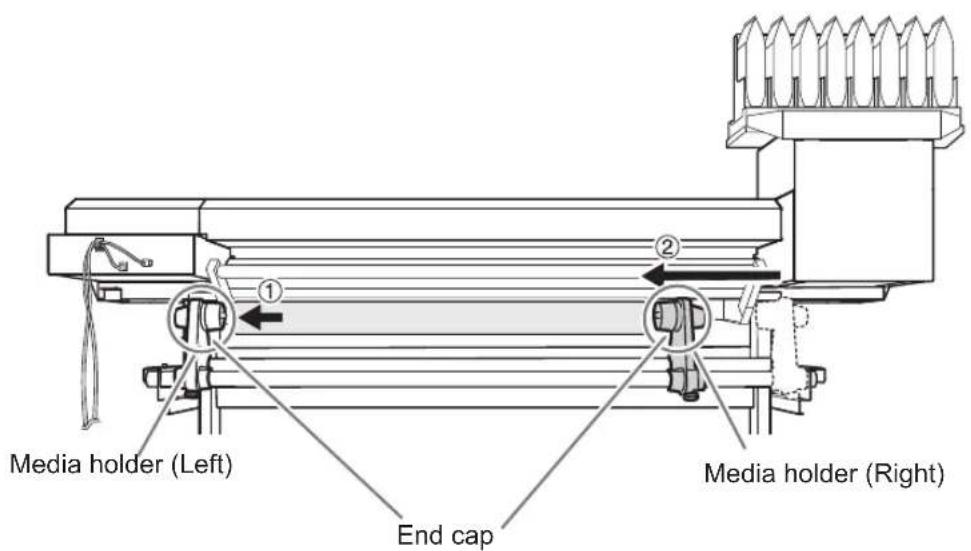
IMPORTANT!
Install conforming to the procedures.
When loading the media make sure that the media holder (Left) is drawn to the left edge. Do not secure the media holder before loading the media. If these procedures are not followed, printing results will be affected because the media will not be fed correctly.
How to use media flanges for paper tubes (cores) with an internal diameter of 2 inches
Note: Media flanges for paper tubes (cores) with an internal diameter of 2 inches are optional items.

5 Hold the outer side of the media holder (Left) and position the left edge of the media to align with the marks.
When deciding the position, hold the both sides of media holders from the outer sides and move it. Do not hold the media directly to move.
CAUTION
Do not hold places other than those instructed.
Otherwise the media may fall off the media holder and cause injury.

IMPORTANT! Decide the left and right side positions of the media finally at this step
After this procedure is completed, if the left and right side positions do not fit the proper position when securing the media with pinch rollers, go back to this step to redo this procedure. If you attempt to forcibly readjust the position of the media simply by pulling on the media itself, printing quality will be affected due to skewed media feed.
6 Secure the media holder by tightening the securing screws slightly.

natural_image
Mechanical assembly diagrams showing two stages of a device with internal components and motion arrows (no text or symbols)2. Pass the media through the machine and secure the media holders.
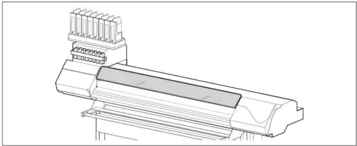
1 Pass the leading edge of the media between the grit rollers and the pinch rollers.
Pass the media over the top of the feed adjuster bar.

② Make sure the front cover is open.
natural_image
Technical line drawing of a mechanical assembly with connectors and housing (no text or symbols)③ Lower the loading lever (rear side).

natural_image
Diagram showing a robotic arm operating a machine with a rotating arrow, no text or symbols present4 Gently hold down the media, and raise the loading lever (front side).
The media is set free.

natural_image
Line drawing of a printer's front panel with a hand operating the cover (no text or symbols)5 Hold the media at the center and pull it out, being sure to keep it straight and all areas of the media to be taut.
Make sure the right edge of the media is in line with the guide line.

IMPORTANT!
If you want to readjust the media position at this step, go back to procedure 1. - ④. If you attempt to forcibly readjust the position of the media simply by pulling on the media itself, printing quality will be affected due to skewed media feed.
6 Lower the loading lever (front side) to secure the media in place.

natural_image
Technical line drawing of a mechanical component with a curved arrow indicating rotation or force (no text or symbols)
① Attach the right and left media clamps.
② Line up the edges of the media with the centers of the holes of the media clamps. Media clamps are magnetic and have are left- and right-sided. Refer to the figure and install the clamps in the correct positions, making sure not to confuse right and left.

IMPORTANT!
Remove when not using roll media.
If roll media is allowed to stand unused in a loaded state for an extended period, the media may sag. This can cause poor printing results and motor errors, so be sure to remove and store such media when not in use.
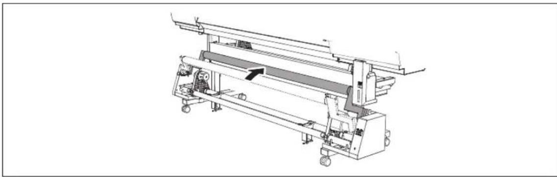
3. Load a paper tube onto the take-up system, and switch on the take-up system power.
This section describes parts that use the take-up system. These instructions describe how to use TUC-3. If using a take-up system other than TUC-3, refer to the user's manual of the take-up system you are using.
1 Raise the dancer roller.
natural_image
Technical line drawing of a mechanical assembly with rollers and conveyor system (no text or symbols)
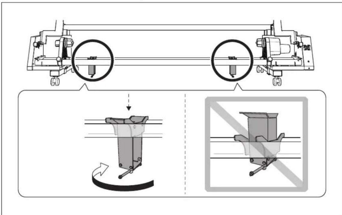
2 Lower the height of each media support to its lowest position by turning the lever.
Make sure that the media supports are on the inner side of the media holders, and turn the media support lever in the direction shown in the figure.
③ ① Secure the motorized media holder.
Secure the motorized media holder firmly using the securing screw.
② Fit the paper tube (core) onto the end cap (Right).
Fit the paper tube securely right to the end of the end cap.

natural_image
Mechanical assembly diagram showing a roller being inserted into a frame with a curved arrow indicating motion (no text or symbols present)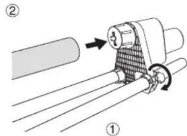
④ ① Loosen the securing screw of the media holder (Left).
② Press the end cap (Left) against the paper tube (core) and insert it.
Move the media holder (Left) and fit the end cap (Left) onto the paper tube (core).

POINT!
Fit the paper tube securely onto the end cap. This prevents skewed feeding when the media is taken up.
IMPORTANT!
Use the paper tube that is included with the roll. If a different roll is used, the media may not be taken because the roll may fail to engage.

Switch on the power of the take-up system.
4. Adjust the position of the media.
1 Set the AUTO switch on the take-up unit to "BACKWARD."
POINT!
It is recommended that you use the BACKWARD setting when using the take-up unit with the machine. When using the TUC-3 as the take-up system, it is not possible to use it with the FORWARD setting if it is adjusted for use with the BACKWARD setting during installation. In the same way, it is not possible to use it with the BACKWARD setting if it is adjusted for use with the FORWARD setting during installation. To change to the BACKWARD or FORWARD setting after installation, contact your authorized Roland DG Corp. dealer.
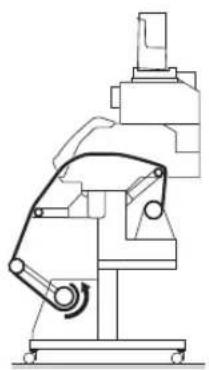
When using the BACKWARD setting


natural_image
Technical line drawing of a mechanical device with no visible text or symbolsWhen using the FORWARD setting

natural_image
Technical line drawing of a mechanical device with no visible text or symbols② Close the front cover.
3

Switch on the sub power.
The print-head carriage moves and detects the width of media. This operation is called initialization. When initialization ends, SETUP remains steadily lit, and the width of the media is displayed on the screen.
3
Press to feed out the media.
Media is fed out 1 mm each time you press . Holding down the key lets you feed out paper continuously.

If using the TUC-3, do not hold the button down when pressing ▲ to adjust the position of the media, do not hold the button down. If ▲ is held down, the machine stops for a fixed interval to protect the motor. If the machine stops, wait for around 5 seconds, and then resume operation.
When using the BACKWARD setting
Feed out the media until its edge just touches the oor as shown in the gure below.

natural_image
Technical line drawing of a printer with two views: top shows internal components, bottom shows mechanical assembly (no text or symbols)When using the FORWARD setting
When the edge of the media is just touching the floor, feed it out another 10 cm (3.94 in.).

natural_image
Technical line drawing of a printer with a paper roll and control panel (no text or symbols)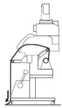
natural_image
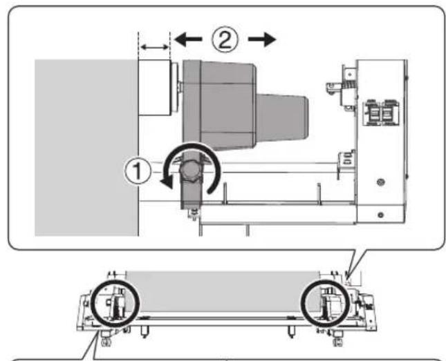
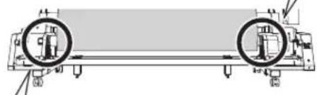
Technical line drawing of a mechanical device with no visible text or symbols④ ① Loosen the securing screw of the motorized media holder.
② Adjust the position of the media holder.
Move both media holders so that it is possible to see around 20 mm of the paper tube (core) from the right edge of the media.
natural_image
Technical diagram of a mechanical assembly with two circular components connected by rods (no text or labels)Good

Not Good
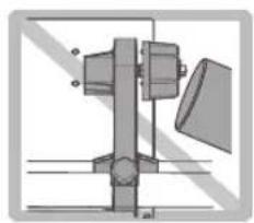
natural_image
Mechanical assembly diagram showing a lever and pivot mechanism (no text or labels)
Secure the paper tube (core) in place with the media holder at both ends so that it does not move out of position or come off the end cap.
⑤ ① Secure the motorized media holder in place.
Secure the motorized media holder firmly using the securing screws.
② Push the media holder (Left) in the direction of the motorized media holder and securely fasten the end cap to the paper tube (core).
Push the media holder firmly until the gap between the media holder and end cap at either end is filled in as shown in the figure.
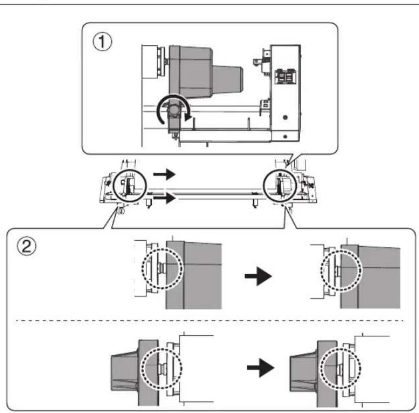
flowchart
graph TD
    A["Step ①: Rotation of Machine Tool"] --> B["Step ②: Comparison of Internal Component"]
    B --> C["Final Assembly"]

    subgraph Step 1
    A --> D["Internal Component"]
    end

    subgraph Step 2
    B --> E["Internal Component"]
    end

    style A fill:#f9f,stroke:#333
    style B fill:#ccf,stroke:#333
    style C fill:#cfc,stroke:#333
6

natural_image
Technical diagram of a mechanical assembly with rotating components and a base view (no text or labels)Secure the media holder (Left) in place.
Secure the motorized media holder firmly using the securing screws.
POINT!
If there is any play when the paper tube is moved from side to side, return to step 2 and redo the procedure.
5. Secure the media on the paper tube (core).

When using the BACKWARD setting
Pass the media around the inner side of the paper tube (core).
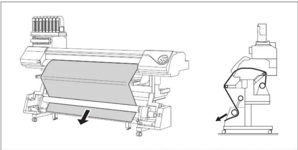
natural_image
Technical line drawing of a printer with a side-view mechanism showing internal components and motion arrows (no text or symbols)When using the FORWARD setting
Pass the media toward the back of the machine from the outside of the paper tube (core).
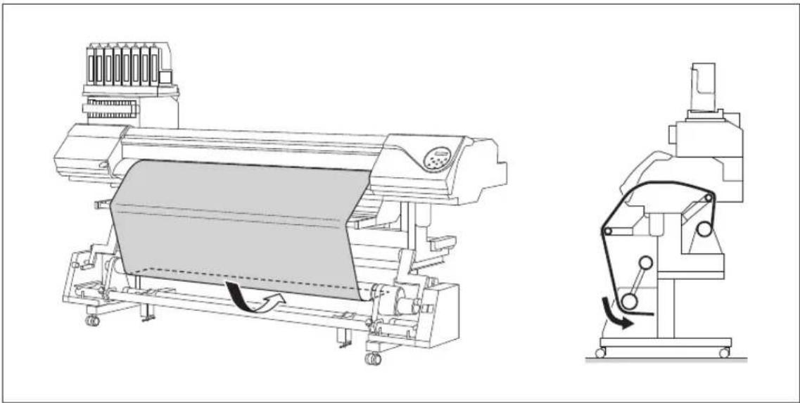
natural_image
Technical line drawing of a printer with internal components and a side-view mechanism (no text or symbols)
When using the BACKWARD setting
While holding the media, slowly lower the dancer bar forward.
Stop lowering the dancer bar when the paper tube (core) starts rotating. When doing so, do not move the hand holding the media away. After this, you will secure the media on the paper tube (core) in this position.

natural_image
Technical line drawing of a printer and its internal mechanism (no text or symbols)When using the FORWARD setting
Pass the media toward the back of the machine from the outside of the paper tube (core). Stop lowering the dancer bar when the paper tube (core) starts rotating. When doing so, do not move the hand holding the media away. After this, you will secure the media on the paper tube (core) in this position.

natural_image
Technical line drawing of a large industrial machine with internal components and directional arrows indicating motion (no text or symbols present)3 Attach the center and both ends of the media to the paper tube (core) using adhesive tape (three locations in total).
① While pulling the media so that it does not sag, secure the center of the media.
② While pulling the media from the center toward the outer edges, and fix the left and right edges.
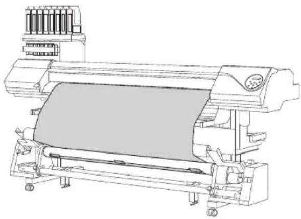
When using the BACKWARD setting
natural_image
Technical line drawing of a large industrial printing press machine (no text or symbols visible)When using the FORWARD setting

natural_image
Technical line drawing of a large industrial machine with a magnified inset showing a close-up of its side panel (no text or symbols present)This completes loading of the media.
IMPORTANT!
When take-up starts, take care that the leading edge of the media does not get folded or bent.
When the media is cut (P. 49"Cutting Off the Media"), the media is set free. Reload the media.
Remove roll media when it is not in use. If roll media is allowed to stand unused in a loaded state for an extended period, the media may sag. This can cause poor printing quality and motor errors, so be sure to remove and store such media when not in use.
Loading Sheet Media
Procedure
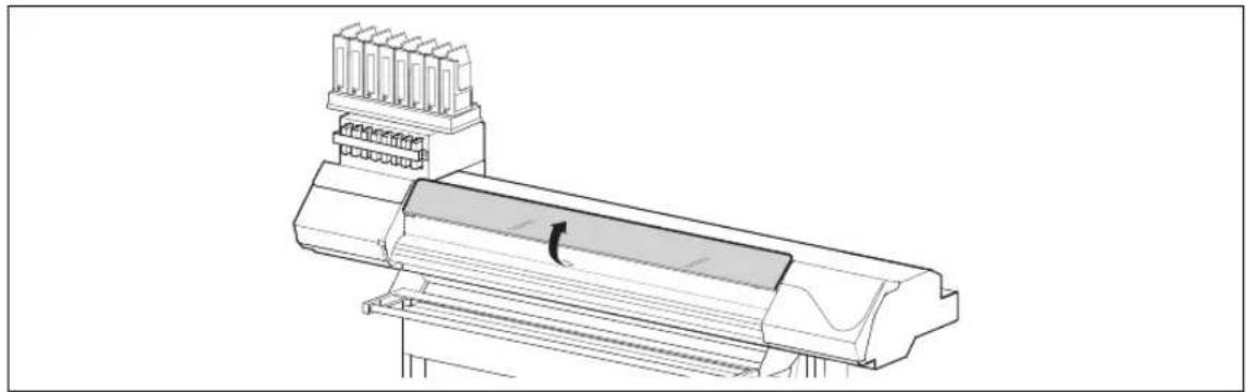
1 Switch off the sub power.
② Open the front cover.
Do not open the front cover until instructed to do so.
natural_image
Technical line drawing of a mechanical assembly with no visible text or symbols3 Draw the media holders to both left and right ends respectively.
Move them to a location where they don't disturb the media when the media is hung down from the rear of the machine. If they disturb the media, remove them with the shaft. For information on how to remove, refer to "Setup Guide".

4 Pass the media through the machine.
See P. 21"Pass the media through the machine and secure the media holders." steps 2. 1-4
5 Align the front edge of the media with the location shown in the figure. Make sure the right edge of the media is in line with the guide line.

6 Lower the loading lever (front side) to secure the media in place.

natural_image
Technical line drawing of a mechanical device with a curved arrow indicating motion or force (no text or symbols)
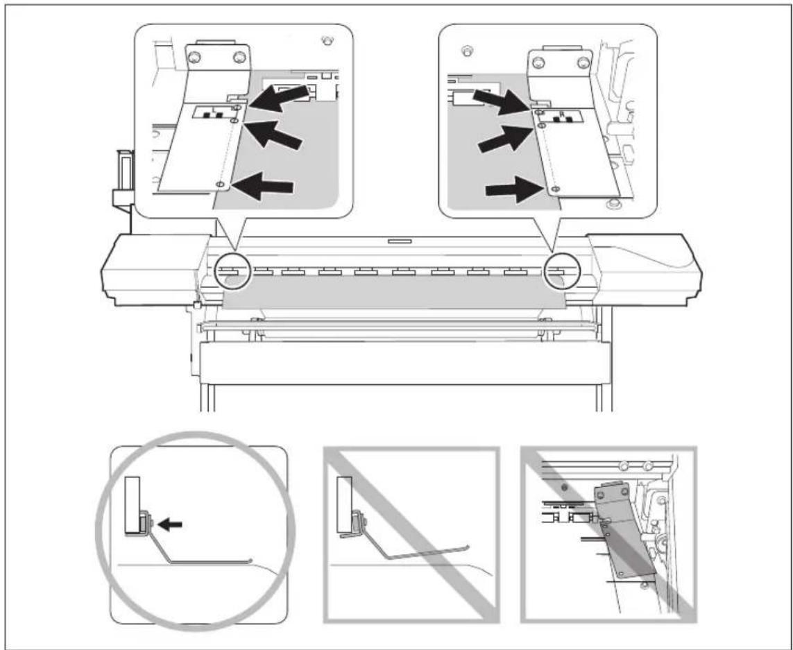
① Attach the right and left media clamps.
② Line up the edges of the media with the centers of the holes of the media clamps. Media clamps are magnetic and have are left- and right-sided. Refer to the figure and install the clamps in the correct positions, making sure not to confuse right and left.

Load the media onto the take-up system.
From P. 25"Load a paper tube onto the take-up system, and switch on the take-up system power." to P. 31"Secure the media on the paper tube (core)."
Performing the Initial Adjustment (Correcting for Misalignment in Bidirectional Printing More Precisely)
Perform the initial adjustment of this machine. This adjustment must be performed in the following cases:
When using this machine for the first time
When changing the media to use
When further correction is required to improve printing, even when simple correction is performed for misalignment in bidirectional printing (P. 88"Correcting for Misalignment in Bidirectional Printing")
Procedure
1
Press
MENU
2
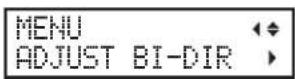
Press several times to display the screen shown at left.
Press ▶, then ▲
3

Press
4

Press ENTER
A test pattern is printed.
When printing ends, press
5
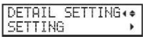
Press .
6

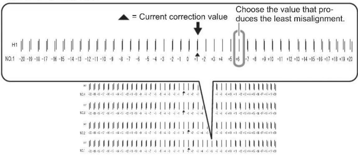
Use and to select a correction value
for No. 1.
Press ▶.
Use ▲ and to select a correction value
for No. 2.
Press ▶.
To decide a correction value
Choose the value that produces the least misalignment of the 2 lines. When wavering between two numbers, select half value.
7
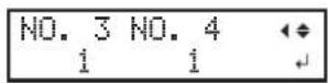
Use and to select a correction value for No. 3.
Press ▶.
Use ▲ and to Select a correction value for No. 4.
8 When you have completed correction value settings, press ENTER
9 Press to go back to the original screen.
About [Media Setting] menu
To ensure the optimal printing according to the media size and type, various setting items are provided in the machine. The machine provides the [Media Setting] menu that guides you through these settings in an interactive mode. Using this menu, you can set all of the basic settings simply by following the instructions on the display.
Since setting details can be stored as a preset menu, you can work efficiently by skipping the setup procedure when using the same type of media. Once the basic settings have been stored in a preset, fine adjustments can be made as necessary.
The items set through the [Media Setting] menu can be also set individually.
Setup of Media ([Media Setting] menu)
Note: If any setting is not needed for each setting item, you can go to the next menu by selecting [Next].
1. Starting the [Media Setting] menu
1 Load media.
Check that no sagging is found on the media. If any sagging exists, the following correction value settings will not function effectively.
P. 18"Loading Media"
2 Press .MENU
3 MENU MEDIA SETTING When the screen on the left is displayed, press ENTER
![To cancel setup Procedure ① Press during setup. ② QUIT SETTING ▶ [YES] NO ▶ MENU ◆ ▶ MEDIA SETTING ▶ Press to Select [Cancel]. Press ENTER . The screen on the left appears again. Selecting [Back] returns you to the screen that was displayed when you pressed MENU .](/content/2026/06/1343677/images/7cba110237c583121e336ae132d76c4c29b84ba60741d3d82367929ae50c69a0.jpg)
2. Adjusting the print head height
1 HEAD HGT LOW [CHANGE] NEXT Press to select [Change]. Press ENTER to confirm.
2
![ROLAND Texart RT-640 - HEAD HGT LOW [CHANGE] NEXT Press to select [Change]. Press ENTER to confirm. - 1](/content/2026/06/1343677/images/4f57046a1c0adc2b8aeb73036a5336a6f377a5ba68b5a08f8cb2dfccf92e7086.jpg)
When the screen on the left is displayed, open the front cover.
3

Move the height-adjustment lever to adjust the head height.
When moving to the [High] direction, the buzzer sounds twice, and to the [Low] direction, the buzzer sounds once.
POINT!
Normally set to [Low]. For media that is wrinkled or comes loose from the platen, set to [High].
4
Close the front cover.
For the individual setting method of this setting item and the description, refer to P. 91"Adjusting Print Head Height to Match Media Thickness"
3.
Performing the position correction of feed direction (Alleviate horizontal stripes)
POINT!
Feed direction means the feed direction of the media. Perform the correction adjusting to the media in advance because horizontal strips are more likely to occur during printing when the movement distance of the media changes subtly depending on the media's type or thickness.
1

Press to select [Execute].
Press ENTER to confirm.
The test pattern of feed correction is printed.
2

When the screen on the left is displayed, press ENTER
3

Use and to set the Correction value.
Press ENTER to confirm.
Current correction value Value to be set
To decide a correction value
Select the value to make the upper/lower rectangular gap and overlap smallest. When wavering between two numbers, select half value.

4
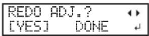
To confirm again/adjust again
Press ◀ to select [Execute].
Press ENTER to confirm.
The test pattern of feed correction is printed again. Go back to step
3 and set again.
To go to the next after correction is completed
Press ▶ to select [Finish].
Press ENTER to confirm.
For the individual setting method of this setting item and the description, refer to P. 89"Alleviating Horizontal Bands (Feed Correction Function)"
4. Performing the correction for misalignment in bidirectional printing
POINT!
This machine prints by the bidirectional mode (in which the print head carriage performs printing during both its outbound pass and return pass). This printing method is called "Bidirectional Printing". This method offers the advantage of being able to shorten printing times, but subtle misalignment occurs during the outbound and return passes. The procedure to correct this and eliminate misalignment is "Bidirectional Correction".
1
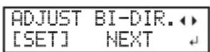
Press to-select [Execute].
Press ENTER to confirm.
The test pattern of bidirectional correction is printed.
2

When the screen on the left is displayed, press


Current correction value Value to be set
To decide a correction value
Choose the value that produces the least misalignment of the 2 lines. When wavering between two numbers, select half value.


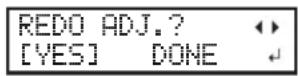
To confirm again/adjust again
Press ◀ to select [Execute].
Press ENTER to confirm.
The test pattern of bidirectional correction is printed again. Go back to step 3 and set again.
To go to the next after correction is completed
Press ▶ to select [Finish].
Press ENTER to confirm.
For the individual setting method of this setting item and the description, refer to P. 88"Correcting for Misalignment in Bidirectional Printing"
5. Saving the setting as preset


Press to select [Save].
Press ENTER to confirm.
If you select [Next], the screen in step 4 is displayed, and the settings you have selected up to this point are not saved as a preset. However, they will remain as the current settings values for the machine.


Press or to select a destination to save the preset.
You can select one of NAME1 to 8.
Press to confirm.

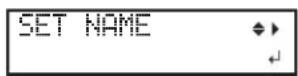
Press or to select character.
Press ▶ to move to the next character.
Select the following characters in the same way.
You can enter up to 15 characters.
Press to confirm.
4
COMPLETED
Press to go back to the original screen.
For the individual setting method of this setting item and the description, refer to P. 86"Fully Utilizing the Preset Function"
This completes the operation of the [Media Setting] menu.

Setting the Printing-start Location
The printing-start location can be set to any location you desire. (It is possible to print even if this settings is not configured.) Note, however, that this setting must be made for each individual page. When the printing of one page finishes, the printing-start location returns to its default value.
Procedure
1 Press to move the media and the print-head carriage.
When a cursor key is pressed, the warm-up operation to move the media or the print-head carriage starts. When the warm-up operation finishes, move the media and the print-head carriage to the position where you want to printing to start.
The printing-start location is determined by the position settings of the feed and scan directions.

Printing-start location in scan (left-right) direction

The base point mark on the right side of the print head carriage is the start location in the scan direction.
② When the location is set, press FUNCTION
3 FUNCTION When the
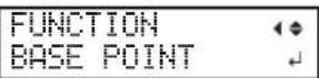
When the screen on the left is displayed, press ENTER to confirm.
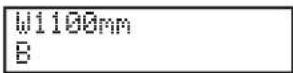
BASE remains steadily lit and when the screen displays the character "B" together with the printable width at the location, setting is completed.
POINT!
Note that the left and right positions are not restored to their defaults for test patterns.
When using the separately available media take-up system (TUC-3), if ▲ is held down, the machine stops for a fixed interval to protect the motor. If the machine stops, wait for around 5 seconds, and then resume operation.
Printing Tests and Normal Cleaning
Before you carry out actual printing, perform a printing test to ensure no dot drop-out occurs. If dot drop-out occurs, perform cleaning of the print heads (Normal Cleaning).
1. Set test print orientation
Note: The factory default setting for test print orientation is "Portrait." When making continuous test prints, it is possible to select print orientation of "Portrait" or "Landscape" from the second print onward. However, if using the optional media take-up system, test prints will be printed in "Portrait" orientation regardless of the print orientation setting.
P. 100"Using the Media Take-up System"
1 Press MENU
2 MENU SUB MENU Press several times to display the screen shown at left.
3 SUB MENU TEST PRINT POS ▶ Press and then to display the screen on the left. Press ▶.
4 TEST PRINT POS ◆ SCAN ▶ FEED ↓ Press and to select [Landscape]. Press ENTER to confirm.
5 Press to go back to the original screen.
2. Make a test print
1 Set the printing-start location.
P. 44"Setting the Printing-start Location"
POINT!
When performing continuous test prints, there is no need to set the printing-start location from the second print onward. However, the printing-start location will be restored to its default and it will be necessary to reset it if any of the following operations are made between prints:
▶ Cutting a sheet
▶ Printing created data
Setting the media free
2 Press FUNCTION
3 FUNCTION CLEANING Press
4

Press ENTER
A test pattern is printed.
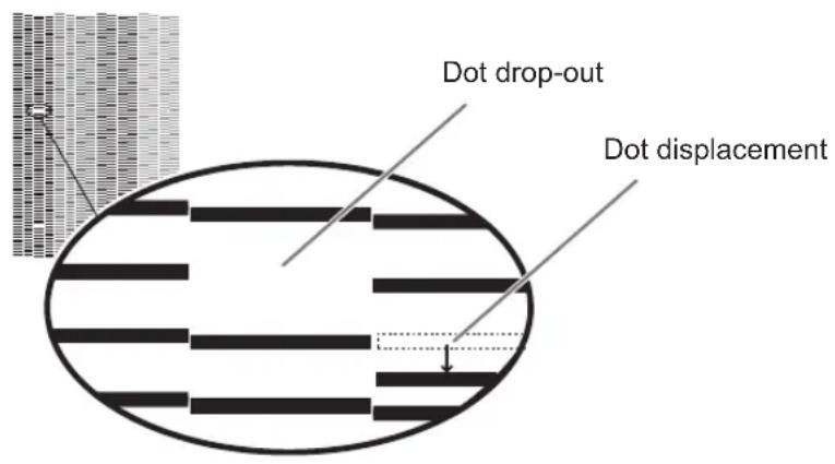
5 If there is no dot drop-out or dot displacement, press to go back to the original screen. If there is dot drop-out or dot displacement, proceed to step 3..
3. Perform normal cleaning
1

2

flowchart
graph TD
    A["CLEANING NORMAL CL."] --> B["CLEANING... >>"]
    B --> C["CLEANING NORMAL CL."]
Press ENTER Normal cleaning starts.
When it finishes, the screen shown on the left appears again.
3 Press to go back to the original screen.
4 Perform a printing test again as per step 2., and make sure that there is no longer any dot drop-out or dot displacement.
If the problem persists, try performing cleaning a second time. If you continue using a printer for a long time, the problem may not be fixed even after performing cleaning a couple of times. If the problem doesn't go away, then try cleaning using a different method.
P. 61"When Normal Cleaning Is Not Effective"
Getting Ready to Receive Data from a Computer
P. 18"Loading Media" and P. 39"Setup of Media" are completed, get the machine ready to receive the data from a computer.
CAUTION
Never touch the print head carriage while printing is in progress.
The print head carriage moves at high speed. Contact may cause injury.
Procedure
1 Close the front cover.
② Make sure stays steadily lit.
If the light does not come on, lower the loading lever.
3 Make sure the top menu is displayed. If the top menu is not displayed, press MENU several times.

POINT!
Printing is not possible in these situations
The machine does not run when the cover is open.
➢ Printing is interrupted when the front cover is opened during printing. Do not open it when printing is in progress.
Data from the computer is not accepted when SETUP is dark.
Data from the computer is not accepted when you are not at the top menu.
Starting Printing
When the operation of P. 47"Getting Ready to Receive Data from a Computer" is completed, it is possible to start printing. To print, the following procedure is required
①Creating printing data
Create printing data using application software such as Adobe Illustrator. For information on how to create the data, refer to the documentation of your application software.
② Sending the output data to this machine using the software RIP
For information about installing and using the software RIP, refer to the documentation for the software RIP.
IMPORTANT!
Points that must be observed when printing
When performing printing, be sure to attach the media clamps. Otherwise the edges of the media may warp and catch on the print heads.
During printing, do not touch media that has already been discharged. Doing so may obstruct media feed or cause the media to rub against the print heads, which may result in a paper jam or damage to the heads.
- When not using the machine, raise the loading lever.
Remaining Ink during Printing
Ensure there is sufficient remaining ink
When the ink in the subtanks runs out (or, if using 4 colors, when all inks of the same color run out) during printing, printing pauses. When printing pauses, the coloring at the seam may be altered when printing resumes. Before performing printing, check the amount of ink remaining in the ink pouches by examining them to see how full they are. Take care particularly when performing lengthy printing.
P. 54 "Out-of-ink Warnings", P. 55 "Ink Pouch Replacement"
Pausing or Canceling Printing
You can pause and cancel printing before it finishes. We do not recommend resuming printing because horizontal bands are produced at the place where printing was paused.
Procedure
1 Press during printing.
Printing operation is paused.
Press again to resume printing.
To cancel printing, go the next procedure without pressing at this stage.
2 TO CANCEL, HOLD DOWN PAUSE KEY
When the screen on the left is displayed, hold down PAUSE for at least 1 second.
Printing operation is canceled.
3 Stop sending printing data from the computer
Cutting Off the Media
Procedure
1 Remove the left and right media clamps.

natural_image
Line drawing of a hand operating a machine with control panel (no text or symbols)② Close the front cover.
③ Make sure stays steadily lit.
4 Press FUNCTION
5

Press to display the screen on the left.
Press ENTER.
The media is cut off.

You can make the setting in the software RIP for automatic media cutoff after printing has finished. For information on how to make the setting, refer to the documentation for the software RIP you are using.
IMPORTANT!
About cutoff operation

When the media clamps are attached, the screen shown on the left appears. Open the front cover, remove the left and right media clamps, and press ENTER.
➢ Be sure to remove the media clamps. If you attempt to perform the cutoff operation while the media clamps are attached, the machine will detect them and interrupt the operation.
Even if you enable the automatic media-cutoff function in the software RIP, if the media clamps are attached, the machine will detect them and interrupt the operation.
When performing cutoff, do not use ▲ to pull the media back. Unless the end of the media has been pulled out to a location to the front of the platen, cutoff may not be performed smoothly.
IMPORTANT!
Give attention to media composition
For some types of media, cutoff is not possible.
Some types of media may remain on the platen after cutoff. If the media remains on the platen, remove it by hand.
Transfer conditions
Recommended transfer conditions (Ink: genuine Roland DG ink compatible with machine)
Heat bonded at 200°C for 60 seconds
Note: Transfer conditions for materials other than cloth may differ from the above.
Other points to remember
To ensure stable transfer quality, we recommend waiting for at least 1 hour after printing before transferring. Insufficient dry time may result in a reduction in quality.
Switch Off
Procedure
1

Switch off the sub power whenever printing is finished.
Hold down the sub power switch for one second or longer.
2

natural_image
Line drawing of a car air conditioner unit with a directional arrow indicating airflow or movement (no text or symbols)Raise the loading lever and remove the media.
When not using the machine, raise the loading lever even if the sub power is on.
IMPORTANT!
Leave the main power switched on at all times.
Never switch off the main power. By switching on the main power, the automatic maintenance function is carried out periodically. If the automatic maintenance is not carried out, it may result in breakdown of this machine such as breakdown of the print heads.
Never switch off the main power or unplug the power cord suddenly while operation is in progress.
Switching off the main power or unplugging the power cord suddenly while operation is in progress may damage the print heads. Be sure to first switch off the sub power. If the main power is accidentally switched off, immediately turn the main and sub power back on.
POINT!
When not using the machine, remove any media and store it in a suitable environment. If the machine is left with the media loaded, the media may be damaged, which may be adversely affect printing. When not using the machine, remove any media and store it in a suitable environment.
P. 16"Media Storage Environment"
3.
Maintenance:
Keeping the Machine in Good Working Order
Ink Pouch Replacement....54
Out-of-ink Warnings 54
Ink Pouch Replacement....55
Maintenance that Should Be Performed Daily....57
Disposing of Discharged Fluid 57
Cleaning....59
Care and Maintenance of the Print Heads....60
When Normal Cleaning Is Not Effective....61
Medium/Powerful Cleaning 61
If Colors are Uneven....62
Mixing the Ink by Shaking the Ink Pouch 62
Light Choke Cleaning....62
Maintenance that Should Be Performed More Than Once a Month...64
When Manual Cleaning Becomes Necessary ....64
Manual Cleaning 65
Maintenance that Should Be Performed Every Six Months....70
Refreshing Subtanks (REFRESH SUBTANK) 70
When Missing Pixels Etc. Cannot be Corrected....73
When Missing Pixels Etc. Cannot be Corrected 73
Replacing Consumable Parts 76
Replacing the Wiper....76
Replacing the Felt Wiper....79
Replacing the Separating Knife.... 82
When Not in Use for a Prolonged Period....84
Keep Performing Maintenance.... 84
Alarm Feature 84
If the Machine has not been Used for Over One Month 84
Out-of-ink Warnings
P. 55"Ink Pouch Replacement"
If using 4 colors (CMYK)

If one ink of the same color runs out, the machine continues printing using the other ink. When all inks of the same color run out, printing pauses and a warning beep sounds.
If using 8 colors (CMYKLcLmOrVi)
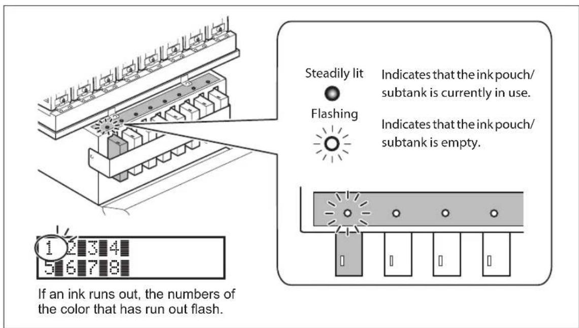
When an ink runs out, printing pauses (unless the factory default settings have been changed,) and a warning beep sounds.
Ink Pouch Replacement
IMPORTANT!
Precautions regarding Ink pouch replacement
➢ Be sure to replace with a pouch of identical type and color.
➢ Install a pouch in each port. If there is a port that does not have a pouch installed, ink may dry up or air may enter the ink path, resulting in malfunction. Depending on the state of the machine, it may take some time to restore operation.
When replacing a pouch, move the ink pouch holder slowly. Ink may leak if the ink pouch holder is subjected to a strong shock, for example if you let go of it partway through.
➢ Never use an ink pouch that has already been used in other machines even if it is of the identical type.
➢ Never mix pouches of different types.
➢ Never insert or remove a partially used ink pouch. Ink may leak.
Do not remove subtanks.
➢ Take care not to drop ink pouches.
WARNING
Never store ink or discharged fluid in any of the following locations:
➢ Any location where high temperature may occur
Near bleach or any other such oxidizing agent or explosive material
▶ Any location within the reach of children
Procedure
1

Pull the ink pouch holder for the empty ink forward.
Raise the ink pouch holder slowly without letting go of it.
2

① Lower the stopper.
② Remove the ink pouch.
If ink gets on the machine or the floor when removing an ink pouch, wipe it off with a dry cloth or similar.
IMPORTANT!
Do not raise an ink pouch holder if there is no ink pouch is installed in it. Doing so may cause air to enter the ink path, resulting in malfunction. It may take some time to restore operation in the event of malfunction.
3

natural_image
Line drawing of two hands holding a tablet device with motion lines indicating movement (no text or symbols)Shake an ink pouch of the same type and color gently.
If ink components precipitate, it will not be possible to print with correct colors.
4

① Install the new ink pouch.
Install the new ink pouch, taking care to use the right color.
② Raise the stopper.
Take care not to crush ink pouches.
5
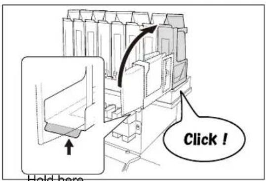
Raise the ink pouch holder.
Raise the ink pouch holder slowly without letting go of it.
IMPORTANT!
When installing an ink pouch and returning the ink pouch holder to its original position, raise the ink holder firmly until it clicks into place. Ink will leak if the ink pouch holder is not returned to the correct position.
Disposing of Discharged Fluid

The drain bottle collects discharged fluid. Dispose of collected material before the bottle becomes full. The message shown in the screen on the left appears when a certain amount of discharged fluid has collected in the bottle. Follow the procedure below to discard the discharged fluid.
Procedure


When the screen on the left is displayed, remove the drain bottle and discard the discharged fluid.
After discarding the discharged fluid, promptly attach the drain bottle to the machine.

natural_image
Simple line drawing of a cylindrical container with liquid and an arrow indicating flow or movement (no text or symbols)Upper limit Discard before this line is passed.

natural_image
Technical line drawing of a mechanical assembly with a valve and housing (no text or symbols)⚠️CAUTION
Before you detach the drain bottle, be sure to wait for the screen to display "EMPTY DRAIN BOTTLE." After discarding the discharged fluid, promptly attach the drain bottle to the machine
Failing to follow this procedure may cause discharged fluid to flow out of the tube and spill, soiling your hands or the floor.


flowchart
graph TD
    A["NOW EMPTY?\n[YES"] NO] --> B["W1200mm"]
    B --> C["SETUP SHEET"]
![Press to display the screen on the left. Press ▶ or and select [YES]. Press ENTER.](/content/2026/06/1343677/images/06b8e1e9384ac8c6ef7e06e03003d0b7e307a884b5d44a24125d6c19291a9a24.jpg)
The display returns to the original screen.
If you did not discard the discharged fluid and selected [NO]
The display also returns to the original screen if you did not discard the discharged fluid and selected [NO] In this case the [EMPTY DRAIN BOTTLE] screen disappears. The message appears again once a certain amount of discharged fluid has collected.
CAUTION
When the [EMPTY DRAIN BOTTLE] screen is displayed, discard the discharged fluid.
If you do not discard the discharged fluid and keep selecting [NO], discharged fluid may overflow from the drain bottle and spill, soiling your hands or the floor.
If it is not possible to check the amount of discharged fluid in the drain bottle
POINT!
Ink may splatter around the inside of the drain bottle making it difficult to check how much discharged fluid the bottle contains. If it is difficult to see the inside, discard the discharged fluid and then clean the drain bottle via the method below.
➢ Clean the inside of the bottle using one of the included cleaning sticks (Cleaning sticks cannot be reused)
If it is not possible to clean the inside using the method above, use the method below.
Procedure
1 Detach the drain bottle from the machine, and attach the other drain bottle included as an accessory to the machine.
② When discarding the liquid in the detached drain bottle, leave about 2 to 3 cm of discharged liquid in the bottom of the bottle.
3 Securely cap the drain bottle.
4 Turn the drain bottle on its side, and roll it so that the remaining discharged liquid wets the inside.
5 Stand the bottle upright and leave it for 1 to 2 hours.
6 If the bottle is not clean enough after the first attempt, repeat steps and 5.
7 Discard the discharged fluid.
WARNING
Never place discharged fluid or ink near open flame.
Doing so may cause fire.
WARNING
To store discharged fluid temporarily, place it in the included drain bottle or in a durable sealed container such as a metal can or polyethylene tank, and cap tightly.
Any spillage or vapor leakage may cause fire, odor, or physical distress.
Dispose of discharged fluid properly, in accordance with the laws in effect in your locale.
Discharged fluid contains toxic ingredients. Never attempt to incinerate discharged fluid or discard it with ordinary trash. Also, do not dispose of it in sewer systems, rivers, or streams. Doing so may have an adverse impact on the environment.
Cleaning
WARNING
Never use gasoline, alcohol, thinner, or any other flammable material. Doing so may cause fire.
Wipe away any ink or grime on the media path and other areas as part of the daily cleaning procedure. Pinch rollers, grit rollers, and the platen are particularly prone to the buildup of grime. Clean by wiping with a cloth moistened by neutral detergent diluted with water then wrung dry.
POINT!
This machine is a precision device, and is sensitive to dust and dirt. Perform cleaning on a daily basis.
➢ Never attempt to oil or lubricate the machine.

Care and Maintenance of the Print Heads
To keep a stable printing condition at all times, the print heads need to be maintained. There are maintenance tasks that should be performed daily and those that should be performed periodically.
Daily care and maintenance
▶ Printing tests and normal cleaning
We recommend performing a printing test and normal cleaning before day-to-day operation.
P. 45"Printing Tests and Normal Cleaning"
Periodic care and maintenance
Medium cleaning/powerful cleaning
Perform if dot drop-out is not corrected after performing normal cleaning.
P. 61"Medium/Powerful Cleaning"
▶ Manual cleaning
Performed periodically based on frequency of use.
P. 65"Manual Cleaning"
Super cleaning
Perform if dot drop-out is not corrected after performing powerful or manual cleaning.
P. 73"When Missing Pixels Etc. Cannot be Corrected"
➢ Refreshing subtanks (REFRESH SUBTANKS)
Perform this procedure once every six months. (This procedure is effective when light choke cleaning does not resolve uneven color issues.)
P. 70"Refreshing Subtanks (REFRESH SUBTANK)"
Maintenance procedures in the event of uneven color issues
Light choke cleaning
Perform this procedure when printed colors are unstable or uneven, e.g., when color density is inconsistent, even if the same data is printed with the same settings.
P. 62"Light Choke Cleaning"
➢ Refreshing subtanks (REFRESH SUBTANKS)
Use this procedure when light choke cleaning does not resolve uneven color issues. (Note that it is necessary to perform this procedure once every six months regardless of whether or not there are problems with uneven colors.)
P. 70"Refreshing Subtanks (REFRESH SUBTANK)"
Note: The print heads are components that wear out. Periodic replacement is required, with the frequency of replacement depending on use. Purchase them from your authorized Roland DG Corp. dealer.
Medium/Powerful Cleaning
When problems such as dot drop-out are not resolved by normal cleaning (P. 45"Printing Tests and Normal Cleaning"), try the more forceful "medium cleaning." If this still does not resolve the problem, try the even more forceful "powerful cleaning."
POINT!
"Medium" and "powerful" cleaning consume more ink than "normal cleaning," and overly frequent use may damage the print heads themselves. Avoid using it more than necessary.
Procedure

Press


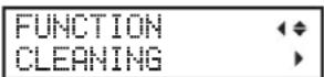
Press



Press and to select "MEDIUM CL." If "MEDIUM CL." is not effective, select "POWERFUL CL."
Press to confirm.


flowchart
graph TD
    A["CLEANING..."] --> B["CLEANING MEDIUM CL."]
"MEDIUM CL."
The screen shown on the left appears, then cleaning starts. When it finishes, the screen shown on the left appears again.

flowchart
graph TD
    A["CLEANING..."] --> B["CLEANING POWERFULL CL."]
"POWERFUL CL."
The screen shown on the left appears, then cleaning starts. When it finishes, the screen shown on the left appears again.

Press to go back to the original screen.
When Powerful Cleaning Is Not Effective
If problems such as dot drop-out persist even after you have performed powerful cleaning several times, then perform manual cleaning. Such cleaning can be effective when carried out periodically, according to the frequency of use.
P. 65"Manual Cleaning"
Mixing the Ink by Shaking the Ink Pouch

natural_image
Line drawing of two hands holding a tablet device with motion lines indicating movement (no text or symbols)If ink components precipitate in the ink pouch, colors may be uneven (unevenness in printed colors). If colors are uneven, first remove the ink pouches, and shake them gently.
IMPORTANT!
Before shaking, wipe off any ink from around the mouth of the ink pouch.
If you do not wipe off the ink, it may splatter when you shake the ink pouch.
When you have finished agitating the ink, reattach the ink pouch immediately.
If you take time to reattach the pouch, it will adversely affect the ink path.
When installing an ink pouch and returning the ink pouch holder to its original position, raise the ink holder firmly until it clicks into place.
Ink will leak if the ink pouch holder is not returned to the correct position.
If uneven color issues are not resolved even after shaking the ink pouches, perform light choke cleaning.
Light Choke Cleaning
IMPORTANT!
Light choke cleaning consumes a lot of ink, and overly frequent use may damage the print heads themselves. Avoid using it more than necessary.
If printing is not performed for several days, printed colors may become unstable or uneven, e.g., when color density is inconsistent, even if the same data is printed with the same settings. In such cases, perform light choke cleaning. This will stabilize printed colors by agitating the ink.
Procedure
1
Press MENU
2
| MENU | |
| SUB MENU |
Press several times to display the screen shown at left.
Press ▶.
3
| SUB MENU | |
| INK CONTROL |
Press several times to display the screen shown at left.
Press ▶.



If the message [EMPTY DRAIN BOTTLE] is displayed on the screen
![ROLAND Texart RT-640 - If the message [EMPTY DRAIN BOTTLE] is displayed on the screen - 1](/content/2026/06/1343677/images/55834a670dbb5d89fbb0d27e4fe673922d5b99d922746fd5db2a85f7bc4641a5.jpg)
When the screen on the left is displayed, discard the discharged fluid. When you attach the empty drain bottle to the machine again and press ENTER, the machine performs the procedure below.
CAUTION
The discharged fluid must be discarded at this stage.
If you do not discard it at this stage, discharged fluid will overflow from the drain bottle during the procedure that follows.
CAUTION
Before you detach the drain bottle, be sure to wait for the screen to display "EMPTY DRAIN BOTTLE."
Failing to follow this procedure may cause discharged fluid to flow out of the tube and spill, soiling your hands or the floor.

natural_image
Technical line drawing of a mechanical component with a valve and handle (no text or symbols)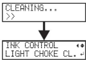
flowchart
graph TD
    A["CLEANING..."] --> B["INK CONTROL LIGHT CHOKE CL."]
The screen on the left is displayed.
When it finishes, the screen shown on the left appears again.

Press to go back to the original screen.
If uneven color issues are not resolved by light choke cleaning, refresh the subtanks.
P. 70"Refreshing Subtanks (REFRESH SUBTANK)"
When Manual Cleaning Becomes Necessary
Perform manual cleaning more than once a month
To keep the stable printing condition at all times, perform the manual cleaning more than once a month. Manual cleaning takes approximately 10 minutes.
Manual cleaning is recommended when the symptoms below occur
It is recommended to perform manual cleaning when any of the symptoms given below occur and cannot be solved by automatic cleaning functions such as normal cleaning.
Replacing the wiper or felt wiper is also an effective means of improving the symptoms.
P. 76"Replacing the Wiper", P. 79"Replacing the Felt Wiper"
Dot drop-out/Dot displacement

natural_image
Two circular gray rings on a textured gray background with horizontal striations (no text or symbols)Dust or other foreign matter adheres to the print heads and impedes correct ink discharge.
Ink drips Dragging dirt
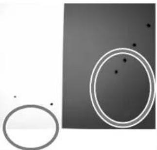
natural_image
Abstract composition of overlapping circles and dots on a dark background (no text or symbols)Ink accumulates on dirty areas around the print heads, and drips onto the media.

natural_image
Abstract black-and-white graphic with a large circular shape and concentric rings (no text or symbols)Dirt accumulates on the area around the print heads and touches the media.
If you use up the cleaning sticks and cleaning liquid used for manual cleaning, purchase new ones from your authorized Roland DG Corp. dealer.
The print heads are components that wear out. Periodic replacement is required, with the frequency of replacement depending on use. Purchase them from an authorized dealer or from Roland DG Corp.
Manual Cleaning
IMPORTANT!
Important notes on this procedure
Before attempting this operation, remove any media.
To prevent the print heads from drying out, finish this procedure in 30 minutes or less. A warning beep sounds after 30 minutes.
➢ Never use any implements other than the included cleaning sticks. Cotton swabs or other lint-producing items may damage the print heads. If you use up the cleaning sticks, purchase new ones from your authorized Roland DG Corp. dealer.
➢ Use one cleaning stick per cleaning session. Reusing cleaning sticks may adversely affect printing results.
Do not put a cleaning stick that has been used for cleaning into the cleaning liquid. It will deteriorate the fluid.
➢ Never rub the print head surface (nozzle surface).
If a warning beep sounds during cleaning
A warning beep sounds 30 minutes after operation starts. Halt operation temporarily, and attach the left and right covers and close the front cover following the instructions in "Manual Cleaning" step 3. (page 68). Press ENTER to finish manual cleaning mode. After that, restart operation from the first procedure.
CAUTION
Be sure to perform operations as specified by the instructions above, and never touch any area not specified in the instructions.
Failure to observe these precautions may cause the machine to move suddenly, resulting in injury.
Required items

Cleaning stick
1. Enter manual cleaning mode.
1 Remove any media.
2

natural_image
Technical line drawing of a mechanical assembly with no visible text or symbolsClose the front cover.

Press



Press



Press and, and select "MANUAL." Press ENTER.


When the screen on the left is displayed, remove the left cover.


Detach the cut rail Press ENTER.

7
CLOSE COVER L
Attach the left cover.
The print-head carriage moves to the left side of the machine.
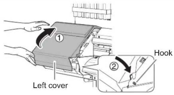
8
OPEN COVER L
Remove the left cover.
9
OPEN COVER R
Remove the right cover.

10
FINISHED?
Preparations are complete when this screen appears.
2. Clean using a cleaning stick.
1

natural_image
Technical line drawing of a mechanical assembly with no visible text or symbolsTouch the location shown in the figure to discharge any static electricity.
② Check that the cut rail has been removed.
If you have forgotten to remove the cut rail, close all covers and redo the procedure from the start. If you continue beyond this point while the cut rail is attached, you may damage the print heads.
3 Clean in the sequence shown in the figure below.
Be especially careful to clean away any fibrous dust (lint).

3. Reattach the left and right covers, and finish manual cleaning mode.
1

Attach the left cover.
② Attach the right cover.
3 Press . ENTER
4

The print-head carriage moves to the right side of the machine, and then the screen shown on the left appears.
Remove the left cover.
5
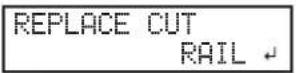
Attach the cut rail.
Press ENTER.

6
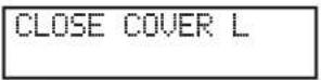
Attach the left cover.
The screen shown on the left appears, then cleaning starts.

flowchart
graph TD
    A["CLEANING..."] --> B["CLEANING MANUAL CL."]
When it finishes, the screen shown on the left appears again.
7
Press to go back to the original screen.
4. Perform a printing test to verify the results of the procedure.
Perform a printing test to check the results.
Perform cleaning using the machine's cleaning feature several times when necessary.
P. 45"Printing Tests and Normal Cleaning"
Refreshing Subtanks (REFRESH SUBTANK)
Refresh the subtanks once every six months to resolve issues with ink component precipitating in the sub-tanks. If this procedure is not performed once every six months, print quality may be adversely affected, e.g. printed colors may be uneven.
This operation is effective when light choke cleaning does not resolve uneven color issues.
IMPORTANT!
Refreshing the subtank consumes more ink than light choke cleaning, and places a strain on the print heads. Undertake this procedure with caution if performing more than once every six months.
1. Enter the [Refresh Subtank] menu.
1
Press
MENU
2

Press several times to display the screen shown at left.
Press ▶.
3

Press several times to display the screen shown at left.
Press ▶, then ▲
4

Press ENTER
2. Start refreshing the subtanks.
1

When the screen on the left is displayed, remove the drain bottle and discard the discharged fluid.
CAUTION
When the [EMPTY DRAIN BOTTLE] screen is displayed, you must discard the discharged fluid
If you do not discard it at this stage, discharged fluid will overflow from the drain bottle during the procedure that follows.
CAUTION
Before you detach the drain bottle, be sure to wait for the screen to display "EMPTY DRAIN BOTTLE."
Failing to follow this procedure may cause discharged fluid to flow out of the tube and spill, soiling your hands or the floor.

natural_image
Technical line drawing of a mechanical assembly with a valve and housing (no text or symbols)② After discarding the discharged fluid, press ENTER
IMPORTANT! Precautions regarding subsequent work
➢ Take care not to drop ink pouches.
When working, move the ink pouch holders slowly. Ink may leak if the ink pouch holder is subjected to a strong shock, for example if you let go of it partway through.
③ PULL INK POUCH HOLDER FORWARD
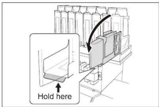
Pull all the ink pouch holders forward.
Lower the ink pouch holders slowly without letting go of them.
4 Press ENTER
5 REMOVE INK POUCH 12345678

① Lower the stopper.
② Remove all the ink pouches.
If ink gets on the machine or the floor when removing an ink pouch, wipe it off with a dry cloth or similar.
6 Press ENTER
7 EMPTY DRAIN BOTTLE When the screen on the left is displayed, remove the drain bottle and discard the discharged fluid.
8 Press ENTER [EMPTY DRAIN BOTTLE] appears on the screen several times. Repeat steps 7 8.
3. Finish refreshing the subtanks.
1
SET INK POUCH 12345678

① Install all ink pouches in the ink pouch holders.
Install the new ink pouches, taking care to use the right color.
② Raise the stopper.
Take care not to crush ink pouches.
Press ENTER
2
RAISE INK POUCH HOLDER
3
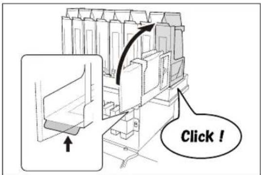
Raise all the ink pouch holders.
Raise the ink pouch holder slowly without letting go of it.
IMPORTANT!
When installing an ink pouch and returning the ink pouch holder to its original position, raise the ink holder firmly until it clicks into place. Ink will leak if the ink pouch holder is not returned to the correct position.
Hold here
4
Press ENTER
5
EMPTY DRAIN BOTTLE
When the screen on the left is displayed, remove the drain bottle and discard the discharged fluid.
6
Press ENTER
INK CONTROL REFRESH SUBTANK
When it finishes, the screen shown on the left appears again.
7
Press to go back to the original screen.
When Missing Pixels Etc. Cannot be Corrected
Perform the procedure below if ink discharge issues such as dot drop-out are not corrected after performing cleaning using the cleaning function (Normal, Medium, Powerful) or manual cleaning.
IMPORTANT!
A large amount of ink will be discharged during this operation. Ink from non-selected colors will also be discharged, although the amount discharged will be smaller than that from selected colors. Perform this operation only when dot drop-out and other issues cannot be corrected even after performing cleaning using the cleaning function (Normal, Medium, Powerful) or manual cleaning.
P. 57"Maintenance that Should Be Performed Daily", P. 61"When Normal Cleaning Is Not Effective", P. 64"Maintenance that Should Be Performed More Than Once a Month"
Procedure
1
Press
MENU
2

Press several times to display the screen shown at left.
Press ▶.
3

Press several times to display the screen shown at left.
Press ▶.
4

When using 8 colors
Press to display the screen on the left.
Press ▶.
When using 4 colors
Press
5

Press or and select the color of the ink that you do not want to perform cleaning for.
Press ▲ or to hide ink colors that you do not want to perform cleaning for or to show ink colors that you do want to perform cleaning for.
Repeat this process to display only the colors of ink that you want to perform cleaning for.
Cleaning will be performed for the inks of the displayed colors only.
6
Press
ENTER
7
When the screen on the left is displayed, remove the drain bottle and discard the discharged fluid.

natural_image
Technical line drawing of a mechanical component with a valve inserted (no text or symbols)CAUTION
The discharged fluid
must be discarded at this stage.
A large amount of ink will be discharged during this operation. The discharged fluid must be discarded at this stage. If you do not discard it at this stage, discharged fluid will overflow from the drain bottle during the procedure that follows.
CAUTION
Before you detach the drain bottle, be sure to wait for the screen to display "EMPTY DRAIN BOTTLE."
Failing to follow this procedure may cause discharged fluid to flow out of the tube and spill, soiling your hands or the floor.
8
Attach the emptied drain bottle to the machine.
Press ENTER.

flowchart
graph TD
    A["CLEANING..."] --> B["SUPER CL. M Y C K ↔"]
The screen on the left is displayed.
When it finishes, the screen shown on the left appears again.
9 Press to go back to the original screen.
POINT! Cleaning the print head surface as a temporary measure
If dot drop-out or dot displacement issues are not resolved, the print head surface may cleaned as a temporary measure. The print head surface (nozzle surface) is a very delicate mechanism, so work must be performed carefully and cautiously.
This procedure is a temporary measure. Depending on symptoms, it may damage normal areas and cause symptoms to worsen. For more information, contact your authorized Roland DG Corp. dealer.
Procedure
Soak up a generous amount of cleaning liquid using a cleaning stick.
② Very gently touch the cleaning stick against the print head surface (nozzle surface).
Very softly press the cleaning stick against the print head so that cleaning liquid soaks into the print head surface (nozzle surface). Never rub the stick or press it forcefully against the print head surface.
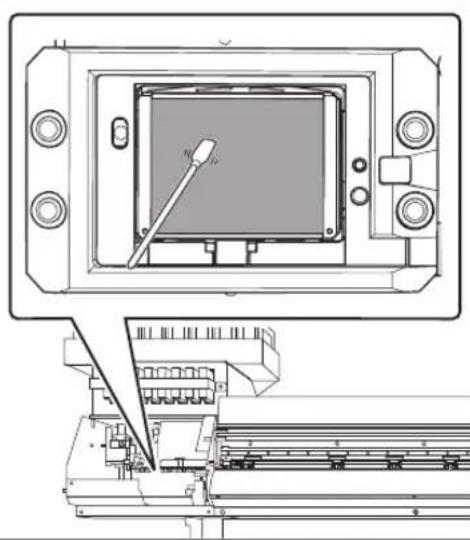
natural_image
Technical line drawing of a mechanical assembly with a central component and a close-up view of a machine tool (no text or symbols)Replacing the Wiper
The wiper is a component that is used when cleaning the print heads. When the screen shown below is displayed on the display screen, it is time for replacement. Replace it with a new item.
TIME FOR WIPER REPLACE
For information about purchasing wipers, contact your authorized Roland DG Corp. dealer.
CAUTION
Be sure to perform operations as specified by the instructions above, and never touch any area not specified in the instructions.
Failure to observe these precautions may cause the machine to move suddenly, resulting in injury.
Required items


Wipers Tweezers
1. Enter the wiper replacement menu.
1
TIME FOR WIPER REPLACE
When the screen on the left is displayed, press ENTER
② Remove any media.
3 Press MENU
4 MENU SUB MENU
Press several times to display the screen shown at left.
Press ▶, and then press twice.
5 SUB MENU MAINTENANCE
Press
6 MAINTENANCE REPLACE WIPER
Press ENTER

The print-head carriage moves to a location where wiper replacement is possible, and then the screen shown on the left appears.
7

Remove the right cover.
8
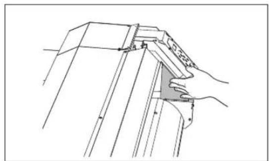
natural_image
Technical line drawing of a mechanical assembly with hands operating a bracket (no text or symbols)Touch the location shown in the figure to discharge any static electricity.
9

Preparations are complete when this screen appears.
2. Replace the wiper.
1 Detach the old wiper.

② Insert a new wiper.
Place the inclined end on the back side. If the wiper is installed round the wrong way, appropriate cleaning will not be possible.

3

Attach the wiper to the hook.
Always attach the wiper to the hook. Failure to do so may result in dot drop-out or other problems.
3. Reattach the right cover, and exit the wiper replacement menu.
1 Attach the right cover.
2 Press ENTER
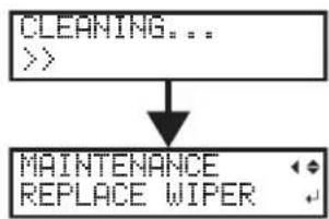
flowchart
graph TD
    A["CLEANING..."] --> B["MAINTENANCE\nREPLACE WIPER"]
After the process to exit the wiper replacement menu, the screen shown on the left appears.
3 Press to go back to the original screen.
4. Perform a printing test to verify the results of the procedure.
Perform a printing test to check the results.
P. 45"Printing Tests and Normal Cleaning"
Replacing the Felt Wiper
The felt wiper is a part used for cleaning the print heads. When the screen shown below is displayed on the display screen, it is time for replacement. Replace it with a new item.
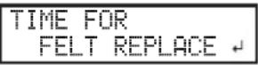
For information about purchasing felt wipers, contact your authorized Roland DG Corp. dealer.
⚠️CAUTION
Be sure to perform operations as specified by the instructions above, and never touch any area not specified in the instructions.
Failure to observe these precautions may cause the machine to move suddenly, resulting in injury.

1. Enter the felt wiper replacement menu.
1 TIME FOR FELT REPLACE When the screen on the left is displayed, press ENTER
2 Remove any media.
3 Press MENU
4 MENU
SUB MENU
Press several times to display the screen shown at left.
Press ▶, and then press twice.
5
SUB MENU
MAINTENANCE
Press ▶
Press ▼.
6 MAINTENANCE ← Press ENTER

flowchart
graph TD
    A[" "] --> B["OPEN COVER R"]
The print-head carriage moves to a location where felt wiper replacement is possible, and then the screen shown on the left appears.
7
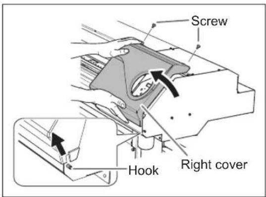
Remove the right cover.
8

natural_image
Line drawing of a hand holding a tool interacting with a mechanical component (no text or symbols)Touch the location shown in the figure to discharge any static electricity.
9

Preparations are complete when this screen appears.
2. Replace the felt wiper
1 Detach the old felt wiper.

2
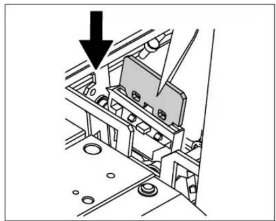
natural_image
Technical diagram of a mechanical assembly with a downward arrow indicating a component (no text or symbols present)Insert a new felt wiper.
3

Attach the hook.
Always attach the wiper to the hook. Failure to do so may result in dot drop-out or other problems.

3. Reattach the right cover, and exit the felt wiper replacement menu.
1 Attach the right cover.
2 Press ENTER

flowchart
graph TD
    A["CLEANING..."] --> B["MAINTENANCE\nREPLACE FELT"]
After the process to exit the felt wiper replacement menu, the screen shown on the left appears.
3 Press to go back to the original screen.
4. Perform a printing test to verify the results of the procedure.
Perform a printing test to check the results.
P. 45"Printing Tests and Normal Cleaning"
Replacing the Separating Knife
If the separating knife becomes dull, replace it with the included replacement knife.
CAUTION
Be sure to perform operations as specified by the instructions above, and never touch any area not specified in the instructions.
Failure to observe these precautions may cause the machine to move suddenly, resulting in injury.
CAUTION
Do not touch the edge of the separating knife.
Doing so may result in injury.
Required items
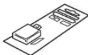
Replacement blade for separating knife
1. Enter the separating knife replacement menu.
1 Remove any media from the platen.
2 Press MENU
3 MENU SUB MENU
Press several times to display the screen shown at left.
Press ▶, and then press twice.
4 SUB MENU MAINTENANCE
Press
5 MAINTENANCE REPLACE KNIFE
Press several times to display the screen shown at left.
Press ENTER.
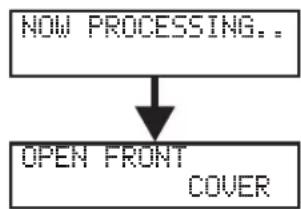
flowchart
graph TD
    A["NOW PROCESSING..."] --> B["OPEN FRONT COVER"]
6 FINISHED?
The print-head carriage moves to a location where knife replacement is possible, and then the screen shown on the left appears.
Open the front cover.
Preparations are complete when this screen appears.
2. Replace the separating knife
1
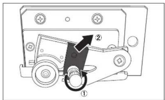
Remove the separating knife.
① Loosen the screw until it slips out.
② Grasp the screw portion, and slowly pull it out in the direction of the arrow. When doing this, do not pull it back toward you.
2

Install a new knife.
The knife is secured in place by the magnet.
3

natural_image
Diagram of a mechanical device with a hand operating it, showing a button and arrow (no text or symbols present)Slowly insert it into the groove.
4
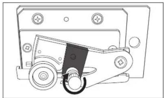
natural_image
Technical line drawing of a mechanical device with wheels and buttons (no text or symbols)Tighten the screw.
Take care to ensure that the knife does not slip out of position at this time.
3. Exit the separating knife replacement menu.
1 Close the front cover.
Press ENTER.
2 Press to go back to the original screen.
Keep Performing Maintenance
Switch on the power once a month
Switch on the sub power once a month. When you turn on the power, the machine automatically performs some operations such as those to keep the print heads from drying out. Allowing the machine to stand completely unused for a prolonged period may damage the print heads, so be sure to switch on the power to perform these automatic operations.
Keep at a constant temperature and relative humidity
Even when the machine is not in use, keep it at a temperature of 15 to 30°C (59 to 86°F) and a relative humidity of 20 to 80% (with no condensation). Temperatures that are too high may degrade the ink and cause malfunction. Temperatures that are too low may cause the ink to freeze and damage the print heads.
Alarm Feature
PRESS THE POWER KEY TO CLEAN
The alarm feature reminds you to switch on the sub power once a month. When the machine remains unused for about one month, this screen appears and a warning beep sounds. If this screen appears, switch on the sub power. When maintenance operations finish, switch off the sub power.
This feature operates when the machine's main power is turned on. Leave the main power switched on at all times even when the machine is to remain out of use for a prolonged period.
If the Machine has not been Used for Over One Month
If the machine has not been used for over one month, refresh the subtanks. If you use the machine straight away without performing this procedure, printing may be adversely affected, e.g. printed colors may be unstable.
P. 70"Refreshing Subtanks (REFRESH SUBTANK)"
4.
Advanced Functions
Fully Utilizing the Preset Function....86
Saving Various Settings as a Name Assigned Preset....86
Loading a Saved Preset....87
Fully Utilizing the Correction Function 88
Correcting for Misalignment in Bidirectional Printing.... 88
Correcting for Misalignment in Bidirectional Printing More Precisely....89
Alleviating Horizontal Bands (Feed Correction Function) 89
Accommodating to the Types and Condition of Media....91
Adjusting Print Head Height to Match Media Thickness 91
Using Transparent Media 92
Using Hard-to-dry Media....94
Using Media that does not Move Smoothly.... 94
Speeding Up Printing for Narrow Media.... 95
Expanding the Printing Area by Reducing the Margins....96
Preventing Soiling of the Media and Dot Drop-Out....97
Using Sticky Media....98
Printing with Crop Marks....99
Printing with Crop Marks....99
Using the Media Take-up System 100
Using the Media Take-up System 100
Saving Various Settings as a Name Assigned Preset
Procedure

Press MENU

Press to display the screen on the left. Press ▶, then ▼


Press

Press or to select one option from NAME1 to NAME8. Press ENTER to confirm.
The present menu settings are saved.


Press or to enter a character. When you have selected the character you want to enter, press ▶.
The characters you can enter are "A" through "Z," "0" through "9," and the "-" character. You can enter up to 15 characters, including spaces.


Press or to enter the next character. Enter the following characters in the same way. When you have finished, press to confirm.

Press to go back to the original screen.
Description
Using the [PRESET] menu lets you easily change a wide variety of settings to optimize them for the media. Up to eight types of presets can be saved. You can assign a name to each one. Using media names for these may aid recognition and clarity. Making changes for each menu item every time you change the media can be troublesome. That's why it can be useful to save the menu-item settings optimized for an often-used type of media as a preset. The next time you use the media, you can change the menu-item settings to the optimal values for the media simply by loading the preset you saved. Menu items that can be saved in presets are listed below.
| [ADJUST BI-DIR SIMPLE SETTING] | P. 88"Correcting for Misalignment in Bidirectional Printing" |
| [ADJUST BI-DIR DETAIL SETTING] | P. 89"Correcting for Misalignment in Bidirectional Printing More Precisely" |
| [CALIBRATION] | P. 89"Alleviating Horizontal Bands (Feed Correction Function)" |
| [SHEET TYPE], [SHEET WIDTH], [SHEET POS.] | P. 92"Using Transparent Media" |
| [SCAN INTERVAL] | P. 94"Using Hard-to-dry Media" |
| [VACUUM POWER] | P. 94"Using Media that does not Move Smoothly" |
| [FULL WIDTHS] | P. 95"Changing the Range of Print-head Carriage Movement" |
| [SIDE MARGIN] | P. 96"Expanding the Printing Area by Reducing the Margins" |
| [MEDIA RELEASE] | P. 98"Using Sticky Media" |
P. 87"Loading a Saved Preset"
Loading a Saved Preset
Procedure

Press



Press to display the screen on the left.
Press ▶ twice.


Press or to select the name of the preset you want to load.
Press ENTER to confirm.

The settings are changed and the screen shown on the left appears.
Description
This loads a saved preset. You can select any one of eight types of presets. (When no names have been assigned, you select from among NAME1 through NAME8.) If you load a preset while SETUP is steadily lit, SETUP starts flashing. After that, when the setup operation is complete, SETUP returns to a steadily lit state.
Correcting for Misalignment in Bidirectional Printing
Procedure

Press



A test pattern is printed.


To decide a correction value
Choose the value that produces the least misalignment of the 2 lines. When wavering between two numbers, select half value.
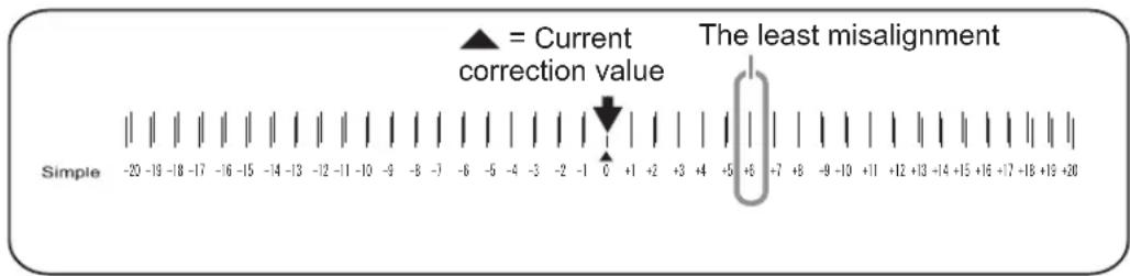

Press to go back to the original screen.
Description
This machine prints by the bidirectional mode (in which the print head carriage performs printing during both its outbound pass and return pass). This printing method is called "Bidirectional Printing." This method offers the advantage of being able to shorten printing times, but subtle misalignment occurs during the outbound and return passes. The procedure to correct this and eliminate misalignment is "Bidirectional Correction." This misalignment varies according to the print head height and the thickness of the media, so we recommend performing correction to match the media you are using.
Correcting for Misalignment in Bidirectional Printing More Precisely
When further correction is required, such as when adjustment made using [SIMPLE SETTING] does not enhance printing, use [DETAIL SETTING] to make corrections.
For instructions on how to perform the work, refer to P. 37"Performing the Initial Adjustment (Correcting for Misalignment in Bidirectional Printing More Precisely)".
Alleviating Horizontal Bands (Feed Correction Function)
Procedure
If using roll media, check that the media is not sagging.
2 Press MENU
3 MENU CALIBRATION Press several times to display the screen shown at left. Press ▶.
4 CALIBRATION Press ENTER
A test pattern is printed.
When printing ends, press , and then press ▶.
5 SETTING 0.00% ▶ -0.40% Press or to select a correction value. Press ENTER to confirm.
To decide a Correction Value
Select the value to make the upper/lower rectangular gap and overlap smallest. When wavering between two numbers, select half value.

6 Press to go back to the original screen.
Description
The movement distance of the media changes subtly depending on the media's thickness. When the movement distance becomes discrepant, horizontal stripes are more likely to occur during printing. We recommend making correction to match the media you are using. Repeat the process of printing a test pattern and entering a correction value several times to find the optimal value.
Depending on the software RIP you are using, you can also make this setting in the software RIP (by, for example, choosing the media type). When you have made the setting in the software RIP, the software RIP's setting is used and the machine's setting is ignored.
Adjusting Print Head Height to Match Media Thickness
Procedure

Press
MENU


Press several times to display the screen shown at left. Press ▶.

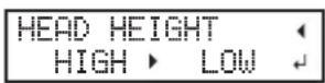
When the screen on the left is displayed, open the front cover.


Move the height-adjustment lever to adjust the head height.
When the lever is moved to the [High] direction, the buzzer sounds twice. When it is moved to the [Low] direction, the buzzer sounds once.

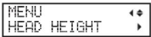
Close the front cover.
The print-head carriage moves to the original position, and then the screen shown on the left appears.

Press to go back to the original screen.
Description
Depending on the media, media may wrinkle or come loose from the platen during printing, increasing the chance of contact with the print heads. When using such media, adjust the print head height to "HIGH."
Setting the print head height to "HIGH" may affect printing results, for example by producing coarser printing results than when "LOW" is set. If this happens, refer to the pages indicated below.
P. 88"Correcting for Misalignment in Bidirectional Printing", P. 37"Performing the Initial Adjustment (Correcting for Misalignment in Bidirectional Printing More Precisely)", P. 97"Preventing Soiling of the Media and Dot Drop-Out"
Using Transparent Media
1. Set media type to "CLEAR."
1 Raise the loading lever.
2 Press MENU
3 MENU
SUB MENU
Press several times to display the screen shown at left.
Press ▶ twice.
4 SHEET TYPE ◆
CLEAR ▶ OPAQUE ↓
Press or▲to select "CLEAR."
Press ENTER to confirm.
2. Set the media width.
1 Press, then.
2
SUB MENU
SHEET WIDTH
Press
3 SHEET WIDTH
1625mm→1200mm
Press or to enter the width of the media.
Press ENTER to confirm.
4 Press to go back to the original screen.
3. Load transparent media on the machine.
Refer to P. 18"Loading Media", and load the media on the machine.
4. Set the position of the right edge of the media.
1 Press MENU
2 MENU
SUB MENU
Press several times to display the screen shown at left.
Press ▶.
3
SUB MENU
SHEET POS.
Press twice.
Press ▶.
SHEET POS. SAVE
The print-head carriage moves to the currently set position, and then the screen shown on the left appears.
4 Open the front cover.
5

Press and to move the print-head carriage (base point mark) to the right edge of the media.
The position indicated by the arrow of the base point mark is set as the position of the right edge of the media
If a fixed period of time passes while the setting procedure is in progress, the menu is forcefully terminated.
If a fixed period of time passes while the setting procedure is in progress, the menu is forcefully terminated and the print-head carriage returns to the home position to prevent the print heads from drying out. In this case, perform step 4. again.
To quit procedure for setting position of right edge of media
1 Close the front cover.
② SHEET POS. CANCEL
Press to display the screen on the left.
3 Press ENTER
The print-head carriage returns to the home position (behind the right cover).
6 After positioning, close the front cover.
Press ENTER to confirm.
Description
For transparent media, the width and position cannot be automatically detected. Therefore, SHEET TYPE must be set to "CLEAR" before the width and attachment position are set manually.
When SHEET TYPE is set to "CLEAR," printing does not stop if the media runs out while printing is in progress. If media runs out while printing is in progress, immediately press PAUSE to quit printing. Otherwise, there is a chance that the platen or other parts may become soiled by ink or that ink may get inside and damage the machine.
Default Setting
[SHEET WIDTH]: 1625 mm
Using Hard-to-dry Media
Procedure

Press MENU


Press several times to display the screen shown at left. Press ▶.


Press several times to display the screen shown at left. Press ▶.

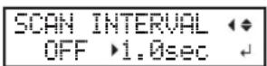
Press or to select a value. Larger values cause the media to move more slowly, enabling you to extend the drying time accordingly. Press to confirm.

Press to go back to the original screen.
Description
Use this setting when ink drying is poor. Depending on the software RIP you are using, you can also make this setting in the software RIP. When you have made the setting in the software RIP, the software RIP's setting is used and the machine's setting is ignored.
Default Setting
Using Media that does not Move Smoothly
Procedure

Press MENU


Press several times to display the screen shown at left. Press ▶.


Press several times to display the screen shown at left. Press ▶.
4
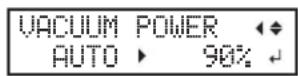
Press or to select a value. 0%–100%
When the media is flimsy and cannot move smoothly, decreasing this value (reducing the suction force) may resolve the problem.
AUTO
The strongest suction force will always be used.
Press to confirm.
5
Press to go back to the original screen.
Description
The platen uses suction to grip the media and keep it stable. The suction force can be adjusted corresponding to the mature and condition of the media. Depending on the software RIP you are using, you can also make this setting in the software RIP. When you have made the setting in the software RIP, the software RIP's setting is used and the machine's setting is ignored.
Default Setting
Changing the Range of Print-head Carriage Movement
Procedure
1
Press MENU
2

Press several times to display the screen shown at left.
Press ▶.
3

Press several times to display the screen shown at left.
Press ▶.
4 FULL WIDTH S OFF FULL
Press or to select a setting.
SHEET
"SHEET" matches the range of print-head carriage movement to the width of the media.
OFF
"OFF" matches the range of print-head carriage movement to the printing data. Movement is limited to the minimum amount necessary, and this can be expected to yield the fastest printing. Note, however, that because the speed of media movement is no longer constant, colors may be uneven.
FULL
"FULL" makes the speed of media movement constant at all times and produces the most stable printing results.
Press to confirm.
5 Press to go back to the original screen.
Description
Fixing the width that the print-head carriage moves can help reduce uneven colors. When this setting is set to "OFF," the movement of the print head carriage is minimized. This does save printing time, but because the speed of media movement is no longer constant, colors may be uneven.
Default Setting
Expanding the Printing Area by Reducing the Margins
Procedure
1 Press.
2 MENU SUB MENU
Press several times to display the screen shown at left.
Press .
3 57\$ /'07 5+&' /#4)+0
Press several times to display the screen shown at left.
Press .
4 SIDE MARGIN 10mm 5mm
Press or and select "5mm."
Press to confirm.
5 Press to go back to the original screen.
Description
This makes the setting for distance from the left or right media clamp to the corresponding left or right edge of the printing area. You can select either "5 mm," "10 mm," or "25 mm." Setting this to "5 mm" lets you expand the printing area.
P. 128"Maximum Printing Area and Margins"
Note, however, that when you are using transparent media, setting this to "5 mm" may result in printing on top of the media clamps.
Default Setting
[SIDE MARGIN]: 10 mm
Preventing Soiling of the Media and Dot Drop-Out
Procedure
1 Press MENU
2 MENU SUB MENU
Press several times to display the screen shown at left.
Press ▶.
3 PERIODIC CL. NONE
Press several times to display the screen shown at left.
Press ▶.
4 PERIODIC CL. NONE
Press or to select a setting. NONE
Automatic cleaning is not performed.
PAGE
Automatic cleaning is performed every time before printing starts. PRDC CL. (JOB)
Automatic cleaning is performed when the cumulative printing time reaches the value you set here. However, if this time is reached during printing, automatic cleaning is performed before the next printing operation starts. Because printing is not paused, uneven color issues due to paused operation do not occur.
PRDC CL. (TIME)
Automatic cleaning is performed when the cumulative printing time reaches the value you set here. When this time is reached during printing, printing pauses and so colors may be uneven.
Press to confirm.
5 Press to go back to the original screen.
Description
In the following cases, ink tends to collect on the surface of the print heads. Under some conditions, this ink may be transferred to the media or cause dot drop-out.
When you use media prone to buildup of static electricity.
When the ambient temperature is low.
When the print-head height is set to "HIGH."
If "PAGE," "PRDC CL. (JOB)," or "PRDC CL. (TIME)" is selected, ink buildup is removed before or during printing. Using these settings results in longer printing times.
Default Setting
Using Sticky Media
Procedure

Press MENU










Press to go back to the original screen.
Description
Some types of media may tend to stick to the platen. Starting printing with the media sticking to the platen may make normal media feed impossible and cause the media to jam. When using such media, set the MEDIA RELEASE menu item to "ENABLE." This peels off the media before starting printing if it is stuck to the platen. Note, however, that media feed may be unstable when printing is performed after executing this operation. Leave this menu item set to "DISABLE" unless you specifically need to change it.
Default Setting
Printing with Crop Marks
Use your software RIP to make the settings for printing crop marks. For information on how to make the settings, refer to the documentation for the software RIP you are using.
IMPORTANT!
Alignment marks and symbols drawn using a graphics software cannot be used as crop marks.
When using Roland VersaWorks, the crop marks are printed as shown in the figure.
Crop mark (Alignment point 3)
Crop mark (Alignment point 1)

natural_image
Simple line drawing of a car with two round wheels (no text or symbols)Crop mark (Alignment point 2)
Crop mark (Base point)
Using the Media Take-up System
Note: The media take-up system ("take-up system") is an optional item.
Note: In this manual, instructions for loading media assume that the TUC-3 will be used.
(From P. 25"Load a paper tube onto the take-up system, and switch on the take-up system power." to P. 31"Secure the media on the paper tube (core).")
Note: For information on how to assemble and install the take-up system, refer to the user's manual of the take-up system.
Note: If using the TUC-3, it is necessary to make adjustments by removing springs and other parts from the control box and frame of the TUC-3. For details, refer to the TUC-3 User's Manual.
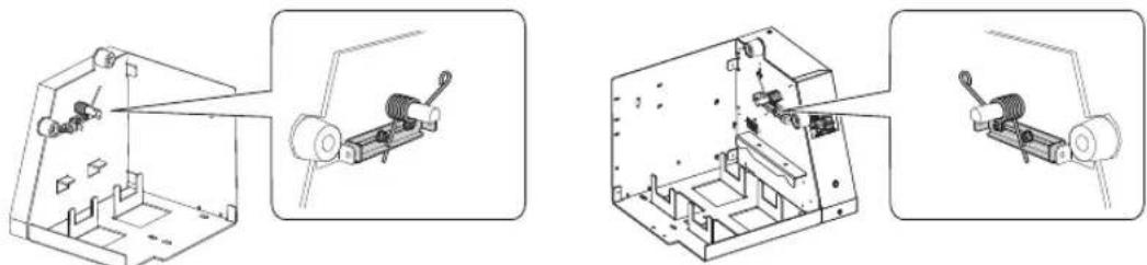
natural_image
Technical line drawings of mechanical components, showing assembly and disassembly views (no text or symbols)5.
To Administrators
Printing Operation Management....102
Printing a System Report....102
Determining What Happens When Ink Runs Out (Only When 8 Colors are
Selected)....102
Displaying the Amount of Media Remaining 103
Making Sure to Verify the Setting for the Amount Remaining Every Time the
Media Is Changed....104
Printing the Amount of Remaining Media....104
System Management of Machine ....106
Setting Menu Language and Units of Measurement....106
Setting Activation Interval for Sleep Mode (Power-saving Feature)......106
Viewing Information about the System of This Machine 107
Returning All Settings to Their Factory Default Values 108
Changing Installation Location....109
Printing a System Report
This prints system information, including a list of setting values.
Procedure
1 Press MENU
2 MENU SUB MENU
Press several times to display the screen shown on the left. Press ▶.
3 SUB MENU SYSTEM REPORT
Press several times to display the screen shown on the left. Press ENTER.
Printing starts.
4 Press to go back to the original screen.
Determining What Happens When Ink Runs Out (Only When 8 Colors are Selected)
This lets you change, according to your purpose, the operation that takes place when a subtank cartridge is empty.
Procedure
1 Press MENU
2 MENU SUB MENU
Press several times to display the screen shown on the left. Press ▶.
3 SUB MENU INK CONTROL
Press several times to display the screen shown on the left. Press ▶ twice.
4 EMPTY MODE STOP ▶ CONT.
Press or to select a setting. "STOP": Printing pauses immediately when a subtank cartridge becomes empty. "CONT." (continue): Printing does not stop when a subtank cartridge becomes empty. When a subtank cartridge becomes empty, a warning beep sounds. Press to confirm.
5 Press to go back to the original screen.
Description
When "STOP" is selected, printing pauses and so colors may be uneven. Ensure a sufficient amount of remaining ink before you begin printing.
When "CONT" is selected, printing does not stop even if ink runs out completely. To replace an ink pouch, wait until printing ends or press PAUSE to pause printing.
Default setting
Displaying the Amount of Media Remaining
You can display how much of the media in use is left. By setting the amount of media currently remaining at the start, the amount remaining will be constantly displayed on the display screen until it reaches zero.
Procedure

Press
MENU

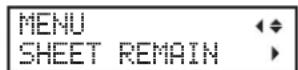





This display is updated.
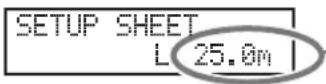
If media has not been loaded, the set value flashes.
Description
If you cancel media loading, for example by removing the media or raising the loading lever, the amount remaining at that time flashes on the screen.
Because the amount of media remaining is not updated automatically when you change the media, redo the setting whenever you change the media. You can also set the machine to display this menu automatically whenever you change the media. See the next section, "Making Sure to Verify the Setting for the Amount Remaining Every Time the Media Is Changed."
Note: The remaining amount that is displayed is only an estimate, and its accuracy is not assured.
Making Sure to Verify the Setting for the Amount Remaining Every Time the Media Is Changed
Set the machine to display SET LENGTH 0.0m ▶ 25.0m ↓ every time media is changed.
Procedure


Press to display the screen on the left. Press ▶.


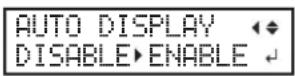
Press or to select "ENABLE." Press ENTER to confirm.
If you set to "ENABLE," you must set the SHEET TYPE menu to "OPAQUE."
P. 92"Using Transparent Media"

Press to go back to the original screen.
Description
Setting this menu to "ENABLE" can keep you from forgetting to redo the setting when you change the media. When doing so, the SHEET TYPE menu item must be set to "OPAQUE" (P. 92"Using Transparent Media"). When SHEET TYPE is set to "CLEAR," [SHEET REMAIN] is not displayed automatically.
Default setting
Printing the Amount of Remaining Media
This prints the amount of media remaining that is displayed at the top menu.
Procedure




Press to display the screen on the left. Press ▶.




Press to go back to the original screen.
Description
You use this when you want to make a record of the remaining length of the media now in use. Printing the amount of media remaining before you change the media enables you to refer to the printed record and use the value to make the setting for the remaining amount the next time you use the media.
Note, however, that if you continue printing, the next printing operation will start on top of the portion where the amount of remaining media is printed. If you want to continue printing, cut off the media before starting the next printing operation.
Setting Menu Language and Units of Measurement
This sets the language and units of measurement displayed on the display screen of the operation panel.
Procedure
1 Hold down and switch on the sub power.
② MENU LANGUAGE
ENGLISH
Press or to select the display (menu)
language.
Press ENTER to confirm.
3 LENGTH UNIT
mm ▶ INCH
Press or▲ to select the measurement unit for length.
Press ENTER to confirm.
4
TEMP. UNIT
" C " F
Press or to select the measurement unit for temperature.
Press ENTER to confirm.
Default setting
Setting Activation Interval for Sleep Mode (Power-saving Feature)
Procedure
1 Press MENU
MENU
SUB MENU
Press several times to display the screen shown on the left.
Press ▶.
3
SUB MENU
SLEEP
Press several times to display the screen shown on the left.
Press twice.
4 INTERVAL 30min ▶ 15min
Press or▲to select a setting.
Press ENTER to confirm.
5 Press to go back to the original screen.
Default setting
[INTERVAL]: 30 min
Viewing Information about the System of This Machine
Note: For information on how to set up a network, refer to "Setup Guide."
Procedure

Press MENU

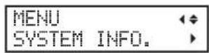
Press several times to display the screen shown on the left.
You can view the following information:
[MODEL]: Model name
[SERIAL NO.]: Serial number
[INK]: Ink type
[FIRMWARE]: Firmware version
[NETWORK]: Network settings such as IP address

flowchart
graph TD
    A["MENU SYSTEM INFO."] --> B["SYSTEM INFO. MODEL"]
    B --> C["MODEL XX-XXXX"]
    B --> D["SYSTEM INFO. SERIAL NO."]
    D --> E["SERIAL NO. XXXXXXX"]
    D --> F["SYSTEM INFO. INK"]
    F --> G["INK XXXXXXX"]
    F --> H["SYSTEM INFO. FIRMWARE"]
    H --> I["FIRMWARE Ver.X.XX"]
    H --> J["SYSTEM INFO. NETWORK"]
    J --> K["NETWORK IP ADDRESS"]
    K --> L["IP ADDRESS 255.255.255.255"]
    L --> M["IP ADDRESS 255.255.255.255"]
    K --> N["NETWORK SUBNET MASK"]
    N --> O["SUBNET MASK 255.255.255.255"]
    O --> P["SUBNET MASK 255.255.255.255"]
    N --> Q["NETWORK GATEWAY ADDR."]
    Q --> R["GATEWAY ADDR. 255.255.255.255"]
    R --> S["GATEWAY ADDR. 255.255.255.255"]
    Q --> T["NETWORK MAC ADDRESS"]
    T --> U["MAC ADDRESS XXXXXXXXXXXX"]
    T --> V["Network MAC ADDRESS"]
    V --> W["Network MAC ADDRESS"]
    style A fill:#f9f,stroke:#333
    style B fill:#ccf,stroke:#333
    style D fill:#cfc,stroke:#333
    style F fill:#fcc,stroke:#333
    style H fill:#cff,stroke:#333
    style J fill:#ffc,stroke:#333
    style K fill:#fcf,stroke:#333
    style L fill:#cff,stroke:#333
    style M fill:#ffc,stroke:#333
    style N fill:#cfc,stroke:#333
    style O fill:#fcf,stroke:#333
    style P fill:#cff,stroke:#333
    style Q fill:#ffc,stroke:#333
    style R fill:#cfc,stroke:#333
    style S fill:#fcc,stroke:#333
    style T fill:#ffc,stroke:#333
    style U fill:#cfc,stroke:#333
Returning All Settings to Their Factory Default Values
This menu returns all settings to their factory defaults. However, the settings for [LANGUAGE], LENGTH UNIT, and TEMP. UNIT are not returned to the factory defaults.
Procedure


Press several times to display the screen shown on the left. Press ▶.

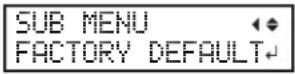
Press several times to display the screen shown on the left. Press ENTER to execute.
Changing Installation Location
Before changing the installation location of the machine, consult your authorized Roland DG Corp. dealer. Roland service technician will move the machine and make adjustments afterwards.
Note: The feed adjuster must be adjusted after the machine has been moved, even if it has only been moved for a short distance, e.g. to a different location on the same floor.
6.
Read this Chapter Whenever you Face a Problem (FAQ)
Attractive Printing is Impossible....112
Printed Results Are Coarse or Contain Horizontal Stripes.... 112
Colors Are Unstable or Uneven.... 113
The Media Becomes Soiled When Printed 114
Color Mixing Occurs.... 114
Media Jam Occurs! 115
The Media has Jammed.... 115
Media Feed is Not Smooth 116
Media Wrinkles or Shrinks 116
Media Feed Is Not Straight 116
Media Feed Is Not Smooth 117
Why Has the Print-head Carriage Stopped Moving?...... 118
What to Do First....118
If the Print Heads Still Do Not Move.... 118
Other Problems....120
The Machine Does Not Move.... 120
Cannot Cut Off the Media. 121
It is not Possible to Check the Amount of Discharged Fluid in the Drain Bottle ....121
A Message Appears ....122
An Error Message Appears....123
Printed Results Are Coarse or Contain Horizontal Stripes
Do the print heads show dot drop-out?
Carry out a printing test and make sure no dot drop-out occurs. If dot drop-out is present, perform head cleaning.
P. 45 "Printing Tests and Normal Cleaning", P. 61 "When Normal Cleaning Is Not Effective"
Are the settings for the [PRESET] menu item appropriate?
If the settings selected with the [PRESET] menu item are not suitable for the type of media, printing may be adversely affected. Choose settings optimized to the media you're using.
P. 39"Setup of Media", P. 86"Fully Utilizing the Preset Function"
Have you carried out bidirectional correction?
When you are performing bidirectional printing, use the [ADJUST BI-DIR] menu item to carry out correction. The optimal adjustment value may vary, depending mainly on the thickness of the media. Set or select an adjustment value that is suited to the media. When further correction is required, such as when adjustment made using [SIMPLE SETTING] does not enhance printing results, use [DETAIL SETTING] to carry out correction.
P. 88"Correcting for Misalignment in Bidirectional Printing", P. 89"Correcting for Misalignment in Bidirectional Printing More Precisely"
Have you carried out feed correction?
Large misalignment in the amount of feed of the media may result in printing results that seem coarse or contain horizontal stripes. Either make the setting in the software RIP to match the type of media you are using, or make the setting for correction on the machine.
P. 89"Alleviating Horizontal Bands (Feed Correction Function)"
Is the print head height appropriate?
Printing when the [HEAD HEIGHT] menu item is set to "HIGH" produces coarser printing results than when set to "LOW." Keep this set to "LOW" except when changing it is necessary, such as when you are using thick media.
P. 91 "Adjusting Print Head Height to Match Media Thickness"
Is the print mode suitable?
Try a higher quality print mode. Depending on the media, smudging may occur when using a high-quality print mode, and results may also vary greatly depending on the settings of your software RIP (such as the color-profile selection). Make settings suited to the media you are using.
Is the media loaded correctly?
If the media is not loaded correctly or media feed is not smooth, printing results may be adversely affected. Load the media correctly.
P. 18"Loading Media"
Is the machine installed in a level and stable location?
Never install the machine in a location where it is tilted or where it may wobble or experience vibration. Also make sure that the print heads are not exposed to moving air. Failure to do so may cause dot drop-out or adversely affect printing results.
Are the ink pouches installed appropriately?
If an ink pouch is not installed appropriately, printing results may be adversely affected.
P. 86"Fully Utilizing the Preset Function"
Colors Are Unstable or Uneven
Are the settings for the [PRESET] menu item appropriate?
If the settings selected with the [PRESET] menu item are not suitable for the type of media, printing results may be adversely affected. Choose settings optimized to the media you're using.
P. 86"Fully Utilizing the Preset Function"
Are the operating parameters set to appropriate values?
Depending on the settings for such menu items as FULL WIDTHS and PERIODIC CL., uneven colors may occur. If the settings have been changed, try restoring them to their factory default values.
P. 95"Changing the Range of Print-head Carriage Movement", P. 97"Preventing Soiling of the Media and Dot Drop-Out"
Did you pause printing?
When printing is paused, the coloring at the seam may be altered when printing resumes. Avoid pausing printing. Under factory default settings, printing pauses when an ink pouch runs out. Before you perform lengthy printing, check the amount of ink remaining in the ink pouches. Printing may also pause when data is not sent from the computer quickly enough. We recommend not performing any other tasks with the computer while printing is in progress.
Is the media loaded correctly?
If the media is not loaded correctly or media feed is not smooth, printing results may be adversely affected. Load the media correctly.
P. 18"Loading Media"
Did you shake the ink pouches gently before installing them?
Shake a new ink pouch before installing it.
P. 116"Media Feed is Not Smooth"
Is the media wrinkled?
If the media is wrinkled and comes loose from the platen, colors may be uneven or printing results may be adversely affected.
P. 116"Media Wrinkles or Shrinks"
Have you not printed for a while?
If printing is not performed for several days, printed colors may become unstable or uneven, e.g., when color density is inconsistent, even if the same data is printed with the same settings.
In such cases, shaking the ink pouches, performing light choke cleaning, and refreshing the subtanks can be effective. (The light choke cleaning and subtank refresh procedures consume large quantities of ink. Read the instructions in this manual carefully and undertake these procedures with caution.)
P. 62 "If Colors are Uneven", P. 70 "Refreshing Subtanks (REFRESH SUBTANK)"
Is the machine installed in a level and stable location?
Never install the machine in a location where it is tilted or where it may wobble or experience vibration. Also make sure that the print heads are not exposed to moving air. Failure to do so may cause dot drop-out or adversely affect printing results.
The Media Becomes Soiled When Printed
Are the print heads dirty?
The following may cause ink to drip on the media during printing:
➢ Buildup of fibrous dust (lint) around the print heads.
Ink transferred to the print heads due to rubbing against the media.
If this happens, clean the print heads manually. We recommend carrying out periodic print head cleaning.
P. 64 "Maintenance that Should Be Performed More Than Once a Month"
Excessively low humidity.
Use the machine in an environment of 35 to 65% RH (non condensation).
Are the pinch rollers or the media clamps dirty?
Periodically clean them.
P. 59"Cleaning"
Do the print heads contact the media?
The height of the print heads may be too low. Also, if the media is not loaded correctly, it may wrinkle or come loose and strike the print heads.
P. 91 "Adjusting Print Head Height to Match Media Thickness", P. 116 "Media Feed is Not Smooth"
Color Mixing Occurs
Has an ink pouch of the wrong color been installed by mistake?
As soon as an ink pouch is installed, ink flows out of the ink pouch into the ink path. Therefore, if an ink pouch is installed incorrectly, ink mixes inside the ink path even if the pouch is removed immediately.
In the event you install an ink pouch of the wrong color, refresh the subtanks. If this fails to resolve issues with color mixing, contact your authorized Roland DG Corp. dealer.
P. 70"Refreshing Subtanks (REFRESH SUBTANK)"
The Media has Jammed
If an error message is displayed because the media has jammed, immediately correct the problem. Failure to do so may damage the print heads.
P. 124"[MOTOR ERROR TURN POWER OFF]"
Are the grit rollers dirty?
Check to make sure the grit rollers are free of buildup of foreign material such as media scraps.
P. 59"Cleaning"
Is the height of the print heads too low?
Try raising the print heads higher. Media may inevitably warp or wrinkle slightly, so adjust the height of the print heads to take this into account.
P. 91"Adjusting Print Head Height to Match Media Thickness"
Are the media clamps mounted?
When you are performing printing, be sure to attach the media clamps.
Is the media loaded straight and securely?
Feed is not smooth when the media is not straight or is tensioned unevenly on the left and right. Reload the media.
P. 18"Loading Media"
Is the media striking another object?
Make sure that nothing touches the media.
P. 18"Loading Media"
Is the media too thick?
Media that is too thick may not only cause unstable feed, but may scrape the print heads, resulting in malfunction. Never use such media.
Is the media warped or wrinkled?
Many factors can cause warping or wrinkling. Refer to the following and correct the problem.
P. 116"Media Wrinkles or Shrinks"
A variety of problems can occur if the media feed is not smooth. This can cause such problems as poor printing results, contact with the media by the print heads, misaligned positioning, or media jams. Take action as follows.
Media Wrinkles or Shrinks
Are the media clamps mounted?
When you're performing printing, be sure to attach the media clamps.
Is the media loaded straight and securely?
Feed is not smooth when the media is not straight or is tensioned unevenly on the left and right. Reload the media.
P. 18"Loading Media"
Is the media sagging?
If sagging media is used, it may come out wrinkled.
Is the temperature of the room too low?
Use the machine in an environment with an ambient temperature of 18 to 25°C (64 to 77°F). If the machine is used at an ambient temperature of less than 18°C (64°F), then depending on the type or width of the media, wrinkling or temperature-caused unevenness may occur. To obtain stable printing results, use the machine in an environment with an ambient temperature of 18 to 25°C (64 to 77°F).
Is the humidity of the room too high?
Use the machine in an environment of 35 to 65% RH (non condensation).
Media Feed Is Not Straight
Are the grit rollers dirty?
Check to make sure the grit rollers are free of buildup of foreign material such as media scraps.
P. 59"Cleaning"
Is the media loaded straight and securely?
Feed is not smooth when the media is not straight or is tensioned unevenly on the left and right. Reload the media.
P. 18"Loading Media"
Is the media striking another object?
Make sure that nothing touches the media.
P. 18"Loading Media"
Is the media too thick?
Media that is too thick may not only cause unstable feed, but may scrape the print heads, resulting in malfunction. Never use such media.
Media Feed Is Not Smooth
Are the grit rollers dirty?
Check to make sure the grit rollers are free of buildup of foreign material such as media scraps.
P. 59"Cleaning"
Is the media striking another object?
Make sure that nothing touches the media. This may adversely affect printing results, even when feed appears to be smooth.
P. 18"Loading Media"
Is the media too thick?
Media that is too thick may not only cause unstable feed, but may scrape the print heads, resulting in malfunction. Never use such media.
If the print-head carriage stops over the platen, take action immediately to prevent the print heads from drying out.
What to Do First

Switch the sub power off, then back on again.
If the media is jammed, then also remove the media.
If the print-head carriage moves to the home position (inside the right cover), it means the operation has ended successfully.
If the print-head carriage still does not move
Try switching off the main power, then again switching on the main power, followed by the sub power.
If the Print Heads Still Do Not Move
If the print heads still do not move, carry out the following emergency response measure, then contact your authorized Roland DG Corp. dealer or us.
Procedure
1 Switch off the main power and open the front cover.
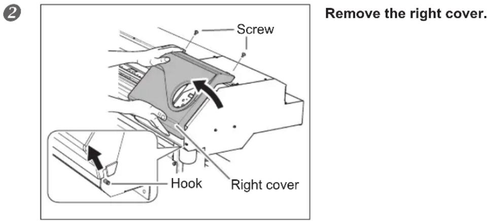
3

Gently move the print-head carriage to the home position.
Stopping at the place where the audible click is heard locks the print-head carriage in place.
4 Gently apply pressure from the right side to make sure the print-head carriage does not move to the left.
If the print-head carriage moves to the left, move it again slowly by applying pressure from the left side and make sure it locks in place.

The Machine Does Not Move
Is the cable connected?
Connect the cable securely.
"Setup Guide"
Is the power switched on?
Switch on the machine's main power, then press the sub power switch and make sure the sub power switch lights up.
P. 17"Switch On!"
Is a cover open?
Close the front, left, and right covers.
Is illuminated?
Printing is not performed when s_n is illuminated. Lower the loading lever.
P. 47"Getting Ready to Receive Data from a Computer"
Is the top menu displayed?
Top menu
W1200mm
If the top menu is not displayed, printing does not start even when data is sent from the computer. To go to the top menu, press MENU, then press
P. 47"Getting Ready to Receive Data from a Computer"
Is a message displayed on the screen?
P. 122"A Message Appears", P. 123"An Error Message Appears"
Is illuminated?
When ☐ PAUSE lights up, operation is paused. To resume, press ☐ PAUSE . ☐ PAUSE goes dark and printing resumes.
P. 49"Pausing or Canceling Printing"
Has ink run out?
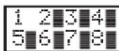
When the screen shown above is displayed, print data cannot be accepted.
If the screen shown above is displayed during printing, the behavior of the machine depends on the EMPTY MODE setting. (Only when 8 colors are selected)
When "STOP" is selected: Printing operation is paused.
When "CONT." is selected: A warning beep sounds, and printing continues until the machine has finished printing the print data it has accepted. In this case, it is also possible to press PAUSE and pause printing.
In both cases, the error can be resolved by replacing the ink pouch with a new one. If there is print data that has not yet been printed remaining in the machine, printing resumes. If there is unsent print data in the computer, printing resumes when the data is resent.
P. 102"Determining What Happens When Ink Runs Out (Only When 8 Colors are Selected)", P. 55"Ink Pouch Replacement"
When using the media take-up system (TUC-3), did you move the media by holding down?
When using the separately available media take-up system (TUC-3), if you move the media by holding down ▲, the machine stops for a fixed interval to protect the motor. If you wait for around 5 seconds you will be able to resume operation.
Is the network routing appropriate?
Try connecting the computer and the machine to the same hub, or connecting them directly using a crossover cable. If this makes it possible to perform printing, it means the problem is in the network itself.
Are the network settings correct?
If the cable connections are secure and no problem is found in the network itself, make sure that the IP address and other such settings are appropriate. The settings on both the machine and the computer must be appropriate. Redo the settings, checking to ensure that the IP address does not conflict with the IP address for another device on the network, that the port setting for the software RIP specifies the IP address set on the machine, that the settings have no typing errors, and for other such problems.
"Setup Guide," P. 107"Viewing Information about the System of This Machine"
Did the software RIP end abnormally?
Make sure the software RIP is running correctly, then switch the machine's sub power switch off and back on. For information about using the software RIP, refer to the documentation included with the software RIP.
Cannot Cut Off the Media.
Is the separating knife mounted?
If the separating knife is not mounted, you cannot cut off the media.
P. 82"Replacing the Separating Knife"
Are the cut rail mounted?
If the cut rail is not mounted, you cannot cut off the media.
P. 82"Replacing the Separating Knife"
It is not Possible to Check the Amount of Discharged Fluid in the Drain Bottle
Is ink splattered around the inside of the drain bottle?
If ink is splattered around the inside of the drain bottle, it may not be possible to check how much discharged fluid the bottle contains.
P. 121"It is not Possible to Check the Amount of Discharged Fluid in the Drain Bottle"
These are the main messages that appear on the machine's display to prompt correct operation. They do not indicate any error. Follow the prompts and take action accordingly.
Ink has run out. Replace the ink pouch indicated by the flashing number with a new pouch.
[PRESS THE POWER KEY TO CLEAN]
This message appears when the machine has been unused for about one month. Switch on the sub power once a month.
P. 84"When Not in Use for a Prolonged Period"
[CLOSE THE COVER (FRONT COVER, RIGHT COVER, or LEFT COVER)]
Close the front, left, and right covers. For safety, the print-head carriage does not operate while a cover is open.
[SHEET NOT LOADED SETUP SHEET]
Load the media. This message appears when an attempt to perform a printing test was made while no media was loaded.
[EMPTY DRAIN BOTTLE]
This appears when a certain amount of discharged fluid collects in the drain bottle. If this screen appears, discard the discharged fluid in the bottle.
P. 57"Disposing of Discharged Fluid"
[INSTALL DRAIN BOTTLE]
Check whether the drain bottle is installed. Install the drain bottle, then press ENTER
P. 57"Disposing of Discharged Fluid"
[TIME FOR MAINTENANCE]
It is time to clean the printer heads manually. After verifying, press ENTER
P. 65"Manual Cleaning"
[TIME FOR WIPER (FELT) REPLACE]
It is time to replace the wiper or felt wiper. After verifying, press ENTER
P. 76"Replacing the Wiper", P. 79"Replacing the Felt Wiper"
[END OF THE SHEET]
The trailing edge of the media was detected during operation. Press any button on the operation panel to clear the message. Load new media.
[REMOVE MEDIA CLAMPS]
This message appears if the media clamps are attached when you try to cut off the media. Open the front cover, remove the left and right media clamps, and press ENTER.
This describes the error messages that may appear on the machine's display, and how to take action to remedy the problem. If the action described here does not correct the problem, or if an error message not described here appears, contact your authorized Roland DG Corp. dealer.
[CAN'T PRINT CROP CONTINUE?]
The size of the data including the crop marks is larger than the printing or cutting area of the loaded media.
To continue printing without correcting this, press ENTER time, the portion extending beyond the printing area and the crop marks are not printed. To stop printing, stop sending data from the computer, then raise the loading lever. Make the printing area wider, for example by replacing the media with a larger piece of media, then send the data again.
The size of the data being printed is too small.
Make the scanning-direction size of the data at least 65 mm (2.6 in). To continue printing without correcting this, press ENTER . At this time, the data is output without printing the crop marks. To stop printing, stop sending data from the computer, then raise the loading lever. Change the size of the data, then send the data again.
[TEMPERATURE IS TOO HIGH \*\*°C]
The temperature of the location where the machine is installed has risen above the ambient temperature at which the machine can operate.
Operation cannot be continued. Switch off the sub power. The displayed temperature is the current ambient temperature of the installation location. Bring the installed location to a temperature at which operation is possible (18 to 25°C (64 to 77°F)) and allow the machine to come to room temperature, then turn on the power.
[TEMPERATURE IS TOO LOW \*\*°C]
The temperature of the location where the machine is installed has fallen below the ambient temperature at which the machine can operate.
Operation cannot be continued. Switch off the sub power. The displayed temperature is the current ambient temperature of the installation location. Bring the installed location to a temperature at which operation is possible (18 to 25°C (64 to 77°F)) and allow the machine to come to room temperature, then turn on the power.
[SERVICE CALL xxxx]
An unrecoverable error occurred, or part replacement that must be performed by a service technician is required.
Note the number displayed on the display screen, then switch off the sub power. After you switch off the power, inform your authorized Roland DG Corp. dealer or Roland Corp. of the number that appeared on the display.
[SHEET TOO SMALL CONTINUE?]
The size of the data is larger than the printing area of the loaded media
To continue printing without correcting this, press ANTHS time, the portion extending beyond the printing area is not printed. To stop printing, stop sending data from the computer, then raise the loading lever. Make the printing area wider, for example by replacing the media with a larger piece of media, then send the data again.
[SHEET SET ERROR SET AGAIN]
The loading lever was lowered while no media was loaded
Raise the loading lever, load the media in the correct position, then lower the lever again.
P. 18"Loading Media"
[SHEET TYPE] is set to "OPAQUE," but transparent media was loaded
Raise the loading lever, set the SHEET TYPE menu item to "CLEAR," then reload the media.
P. 92"Using Transparent Media"
The loaded media is too small
Press any button on the operation panel to clear the message. Replace with media of usable size.
[DATA ERROR CANCELING...]
Printing was stopped because a problem was found in the data received.
Operation cannot be continued. Check for a problem with the connector cable or the computer, and redo the operation from the step of loading the media.
[CLEANING ERROR]
Light choke cleaning was stopped due to some kind of operation.
The ongoing task cannot be continued. Switch the sub power off by holding down the switch for one second or longer, and then back on. Then perform the [LIGHT CHOKE CL.] from the beginning.
P. 62"Light Choke Cleaning"
[CANCELED FOR PUMP PROTECTION]
The printer made an emergency stop because the following state has continued for 10 minutes or longer while cleaning (normal, medium, powerful, super, light choke cleaning, subtank refresh, or automatic cleaning while sub power was switched off) was in progress or during the first ink filling procedure for the machine.
The machine ran out of ink
Operation cannot be continued. Switch off the sub power. After you switch off the power, contact the authorized Roland DG Corp. dealer where you purchased the machine or Roland Corp.
[AVOIDING DRY-UP TURN POWER OFF]
The print heads were forced to the home position to prevent them from drying out.
Operation cannot be continued. Switch the sub power off, then back on.
[SET HEAD HEIGHT TO xxx]
The height of the print heads is lower than the height specified in the software RIP.
This warning indicates that the height of the print heads is too low for the media thickness specified in the software RIP. The print-head carriage moves to a location where you can operate the height-adjustment lever.
Adjust to the displayed height, then press ENTER.
P. 91 "Adjusting Print Head Height to Match Media Thickness"
[MOTOR ERROR TURN POWER OFF]
A motor error occurred.
Operation cannot be continued. Switch off the sub power. Next, eliminate the cause of the error, then immediately switch on the sub power. If the machine is allowed to stand with the error uncorrected, the print
heads may dry out and become damaged. This error may be caused by such factors as a mistake in loading the media, a media jam, or an operation that pulls the media with excessive force.
The media has jammed
Carefully remove the jammed media. The print heads may also be damaged. Perform head cleaning, then perform a printing test and check the results.
The media was pulled with excessive force
Excessive tension was applied to the media, and additional action is necessary to recover from this state. First, raise the loading lever and adjust the media to create a small amount of slack, then switch on the sub power.
[PINCHROLL ERROR LOWER PINCHROLL]
This message appears when the loading lever was raised during initialization or after the media was loaded.
The error is cleared automatically after a short wait. Load the media correctly again.
[WRONG HEAD IS INSTALLED]
An unusable print head has been installed.
Operation cannot be continued. After you switch off the sub power, contact the authorized Roland DG Corp. dealer where you purchased the machine or Roland Corp.
[CANCELED FOR MOTOR PROTECTION]
Either of the following menu items is to be started in a row within 10 minutes:
▶ Ink filling when purchasing this machine
PUMP UP
HEAD WASH
REFRESH SUBTANK
Press any key other than the sub power switch to cancel the error message. Allow the machine to stand for approximately 10 minutes before resuming operation. These menu items require the pump motor to turn for a long time. When performing these menu items in a row, take an interval of at least 10 minutes to prevent damage to the machine due to the overheating of pump motor.
7.
Main Specifications
Printing Area 128
Maximum Printing Area and Margins....128
Maximum Printing Area When Using Crop Marks .....129
The Media-cutoff Location During Continuous Printing ......129
Locations of the Power Rating and Serial Number Labels .....130
Specifications....131
Maximum Printing Area and Margins

A: Setting of the [SIDE MARGIN] menu item (5 mm, 10 mm (default setting), or 25 mm) B: Width clamped by the media clamp (approx. 5 mm)
*1 The width of the left and right margins is the total of A and B. In the following cases, however, the setting for A itself becomes the width of the margin.
- When media has been loaded without installing the media clamps
- When the SHEET TYPE menu item is set to [CLEAR] (regardless of whether the media clamps are present)
*2 The width of the right margin can be changed by making the setting of base point (printing-start location).
P. 44"Setting the Printing-start Location"
Maximum Printing Area When Using Crop Marks
The maximum printing area when crop marks are used is reduced from the maximum printing area when crop marks are not used by an amount equal to the crop marks.

The Media-cutoff Location During Continuous Printing
When a media-cutoff command is sent from the computer, the cutoff location on the media is as shown in the figure below.
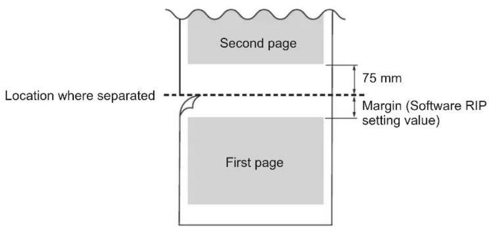



| RT-640 | ||
| Printing technology Piezoelectric inkjet | ||
| Media | Width 259 to 1,625 mm (10.2 to 64 in.) | |
| Thickness Maximum 1.0 mm (39 mil) | ||
| Roll outer diameter Maximum 210 mm (8.3 in.) | ||
| Roll weight Maximum 40 kg (88 lbs.) | ||
| Core diameter (*1) 76.2 mm (3 in.) or 50.8 mm (2 in.) | ||
| Printing width (*2) Maximum 1,615 mm (63.6 in.) | ||
| Ink pouches Types Exclusive sublimation ink pouch | ||
| Printing resolution (dots per inch) Maximum 1,440 dpi | ||
| Distance accuracy (*3) | Error of less than ±0.3% of distance traveled, or ±0.3 mm, whichever is greater | |
| Connectivity Ethernet (10BASE-T/100BASE-TX, automatic switching) | ||
| Power-saving function Automatic sleep feature | ||
| Power requirements AC 100 to 240 V ±10%, 1.5 A, 50/60 Hz | ||
| Power consumption | During operation Approx. 140 W | |
| Sleep mode | Approx. 31 W | |
| Acoustic noise level | During operation 62 dB (A) or less | |
| During standby | 49 dB (A) or less | |
| Dimensions (with stand) | 2,650 mm (W) x 795 mm (D) x 1,600 mm (H)(104.4 (W) x 31.3 (D) x 63 (H) in.) | |
| Weight (with stand) | 160 kg (353 lbs) | |
| Environment | Power on | Temperature: 18 to 25 °C (64.4 to 77 °F), humidity: 35 to 65 %RH (non-condensing) |
| Power off | Temperature: 15 to 30 °C (59 to 86 °F), humidity: 20 to 80 %RH (non-condensing) | |
| Accessories | Exclusive stands, power cord, media clamps, media holder, replacement blades for separating knife, User's Manual, etc. | |
*1
The media holder of this machine is exclusive use for the media of paper tube (core) inner diameter 3 inches. To use 2 inches media, the optional media flanges are required.
*2
The length of printing is subject to the limitations of the program.
*3
➢ Media type: Media specified by Roland DG Corp.
Temperature: 25°C (77°F), humidity: 50%
➢ Roll media must be loaded correctly.
Excluding expansion/contraction of the media
All corrections or adjustment function of this machine have been made properly.
▶ Print travel: 1 m
Roland

- Machine Overview ....5
- Basic Operation ...... 15
- Maintenance: Keeping the Machine in Good Working Order....53
- Advanced Functions....85
- To Administrators ....101
- Read this Chapter Whenever you Face a Problem (FAQ).... 111
- Main Specifications ....127
- 1.
- Machine Overview
- This Machine
- Back
- Front Cover Interior/Print Head Area
- Media clamps
- Pinch roller
- Print-head carriage
- Cutter guide
- Grit rollers
- Platen
- Operation Panel
- Display screen
- BASE POINT light
- FUNCTION key
- MENU key
- SETUP light
- Cursor keys
- PAUSE key
- ENTER key
- BUSY light
- Sub power switch
- Panel Notation
- Language and Unit Menu
- Function Menu
- Ink pouches
- Storage
- Warning Labels
- 2.
- Basic Operation
- Types of Media
- Conditions for Usable Media
- Maximum roll weight
- Other conditions
- Media Storage Environment
- Switch On!
- Procedure
- Sleep Mode (Power-saving Feature)
- Loading Roll Media
- CAUTION
- Install the media on the media holder.
- ② Open the front cover.
- IMPORTANT!
- Install conforming to the procedures.
- How to use media flanges for paper tubes (cores) with an internal diameter of 2 inches
- Hold the outer side of the media holder (Left) and position the left edge of the media to align with the marks.
- Do not hold places other than those instructed.
- IMPORTANT! Decide the left and right side positions of the media finally at this step
- Pass the media through the machine and secure the media holders.
- Hold the media at the center and pull it out, being sure to keep it straight and all areas of the media to be taut.
- Lower the loading lever (front side) to secure the media in place.
- Remove when not using roll media.
- Load a paper tube onto the take-up system, and switch on the take-up system power.
- Raise the dancer roller.
- Lower the height of each media support to its lowest position by turning the lever.
- POINT!
- Adjust the position of the media.
- Set the AUTO switch on the take-up unit to "BACKWARD."
- When using the BACKWARD setting
- When using the FORWARD setting
- ② Close the front cover.
- Switch on the sub power.
- Press to feed out the media.
- Secure the media holder (Left) in place.
- Secure the media on the paper tube (core).
- Loading Sheet Media
- Performing the Initial Adjustment (Correcting for Misalignment in Bidirectional Printing More Precisely)
- 1
- 2
- 3
- 4
- 5
- 6
- To decide a correction value
- About [Media Setting] menu
- Setup of Media ([Media Setting] menu)
- Starting the [Media Setting] menu
- Load media.
- Press .MENU
- MENU MEDIA SETTING When the screen on the left is displayed, press ENTER
- Adjusting the print head height
- HEAD HGT LOW [CHANGE] NEXT Press to select [Change]. Press ENTER to confirm.
- Performing the correction for misalignment in bidirectional printing
- Saving the setting as preset
- Setting the Printing-start Location
- Press to move the media and the print-head carriage.
- The printing-start location is determined by the position settings of the feed and scan directions.
- Printing-start location in scan (left-right) direction
- ② When the location is set, press FUNCTION
- FUNCTION When the
- Printing Tests and Normal Cleaning
- Set test print orientation
- Press MENU
- Make a test print
- Press FUNCTION
- Perform normal cleaning
- Getting Ready to Receive Data from a Computer
- Printing is not possible in these situations
- Starting Printing
- ①Creating printing data
- ② Sending the output data to this machine using the software RIP
- Points that must be observed when printing
- Remaining Ink during Printing
- Ensure there is sufficient remaining ink
- Pausing or Canceling Printing
- Cutting Off the Media
- About cutoff operation
- Give attention to media composition
- Transfer conditions
- Recommended transfer conditions (Ink: genuine Roland DG ink compatible with machine)
- Other points to remember
- Switch Off
- 3.
- Maintenance:
- Keeping the Machine in Good Working Order
- Out-of-ink Warnings
- If using 4 colors (CMYK)
- If using 8 colors (CMYKLcLmOrVi)
- Ink Pouch Replacement
- Precautions regarding Ink pouch replacement
- WARNING
- Never store ink or discharged fluid in any of the following locations:
- Pull the ink pouch holder for the empty ink forward.
- Shake an ink pouch of the same type and color gently.
- ① Install the new ink pouch.
- ② Raise the stopper.
- Raise the ink pouch holder.
- Disposing of Discharged Fluid
- ⚠️CAUTION
- If you did not discard the discharged fluid and selected [NO]
- If it is not possible to check the amount of discharged fluid in the drain bottle
- Cleaning
- Care and Maintenance of the Print Heads
- Daily care and maintenance
- ▶ Printing tests and normal cleaning
- Periodic care and maintenance
- Medium cleaning/powerful cleaning
- ▶ Manual cleaning
- Super cleaning
- ➢ Refreshing subtanks (REFRESH SUBTANKS)
- Maintenance procedures in the event of uneven color issues
- Light choke cleaning
- Medium/Powerful Cleaning
- When Powerful Cleaning Is Not Effective
- Mixing the Ink by Shaking the Ink Pouch
- Press MENU
- If the message [EMPTY DRAIN BOTTLE] is displayed on the screen
- Press to go back to the original screen.
- When Manual Cleaning Becomes Necessary
- Perform manual cleaning more than once a month
- Manual cleaning is recommended when the symptoms below occur
- Manual Cleaning
- Enter manual cleaning mode.
- Clean using a cleaning stick.
- ② Check that the cut rail has been removed.
- Clean in the sequence shown in the figure below.
- Reattach the left and right covers, and finish manual cleaning mode.
- ② Attach the right cover.
- Press . ENTER
- 7
- Perform a printing test to verify the results of the procedure.
- Refreshing Subtanks (REFRESH SUBTANK)
- Enter the [Refresh Subtank] menu.
- Start refreshing the subtanks.
- ② After discarding the discharged fluid, press ENTER
- IMPORTANT! Precautions regarding subsequent work
- ③ PULL INK POUCH HOLDER FORWARD
- Pull all the ink pouch holders forward.
- Press ENTER
- REMOVE INK POUCH 12345678
- Press ENTER
- EMPTY DRAIN BOTTLE When the screen on the left is displayed, remove the drain bottle and discard the discharged fluid.
- Press ENTER [EMPTY DRAIN BOTTLE] appears on the screen several times. Repeat steps 7 8.
- Finish refreshing the subtanks.
- When Missing Pixels Etc. Cannot be Corrected
- POINT! Cleaning the print head surface as a temporary measure
- Replacing the Wiper
- Enter the wiper replacement menu.
- Replace the wiper.
- Detach the old wiper.
- ② Insert a new wiper.
- Attach the wiper to the hook.
- Reattach the right cover, and exit the wiper replacement menu.
- Attach the right cover.
- Press ENTER
- Press to go back to the original screen.
- Replacing the Felt Wiper
- Enter the felt wiper replacement menu.
- Replace the felt wiper
- Detach the old felt wiper.
- Attach the hook.
- Reattach the right cover, and exit the felt wiper replacement menu.
- Replacing the Separating Knife
- Enter the separating knife replacement menu.
- Replace the separating knife
- Exit the separating knife replacement menu.
- Keep Performing Maintenance
- Switch on the power once a month
- Keep at a constant temperature and relative humidity
- Alarm Feature
- If the Machine has not been Used for Over One Month
- 4.
- Advanced Functions
- Saving Various Settings as a Name Assigned Preset
- Description
- Loading a Saved Preset
- Correcting for Misalignment in Bidirectional Printing
- Correcting for Misalignment in Bidirectional Printing More Precisely
- Alleviating Horizontal Bands (Feed Correction Function)
- Adjusting Print Head Height to Match Media Thickness
- Using Transparent Media
- Set media type to "CLEAR."
- Set the media width.
- Load transparent media on the machine.
- Set the position of the right edge of the media.
- Default Setting
- Using Hard-to-dry Media
- Using Media that does not Move Smoothly
- AUTO
- Changing the Range of Print-head Carriage Movement
- SHEET
- OFF
- FULL
- Expanding the Printing Area by Reducing the Margins
- Preventing Soiling of the Media and Dot Drop-Out
- PAGE
- PRDC CL. (TIME)
- Using Sticky Media
- Printing with Crop Marks
- When using Roland VersaWorks, the crop marks are printed as shown in the figure.
- Using the Media Take-up System
- 5.
- To Administrators
- Printing a System Report
- Determining What Happens When Ink Runs Out (Only When 8 Colors are Selected)
- Displaying the Amount of Media Remaining
- Making Sure to Verify the Setting for the Amount Remaining Every Time the Media Is Changed
- Printing the Amount of Remaining Media
- Setting Menu Language and Units of Measurement
- Setting Activation Interval for Sleep Mode (Power-saving Feature)
- Viewing Information about the System of This Machine
- Returning All Settings to Their Factory Default Values
- Changing Installation Location
- 6.
- Read this Chapter Whenever you Face a Problem (FAQ)
- Printed Results Are Coarse or Contain Horizontal Stripes
- Do the print heads show dot drop-out?
- Are the settings for the [PRESET] menu item appropriate?
- Have you carried out bidirectional correction?
- Have you carried out feed correction?
- Is the print head height appropriate?
- Is the print mode suitable?
- Is the media loaded correctly?
- Is the machine installed in a level and stable location?
- Are the ink pouches installed appropriately?
- Colors Are Unstable or Uneven
- Are the operating parameters set to appropriate values?
- Did you pause printing?
- Did you shake the ink pouches gently before installing them?
- Is the media wrinkled?
- Have you not printed for a while?
- The Media Becomes Soiled When Printed
- Are the print heads dirty?
- Are the pinch rollers or the media clamps dirty?
- Do the print heads contact the media?
- Color Mixing Occurs
- Has an ink pouch of the wrong color been installed by mistake?
- The Media has Jammed
- Are the grit rollers dirty?
- Is the height of the print heads too low?
- Are the media clamps mounted?
- Is the media loaded straight and securely?
- Is the media striking another object?
- Is the media too thick?
- Is the media warped or wrinkled?
- Media Wrinkles or Shrinks
- Is the media sagging?
- Is the temperature of the room too low?
- Is the humidity of the room too high?
- Media Feed Is Not Straight
- Media Feed Is Not Smooth
- What to Do First
- If the print-head carriage still does not move
- If the Print Heads Still Do Not Move
- The Machine Does Not Move
- Is the cable connected?
- Is the power switched on?
- Is a cover open?
- Is illuminated?
- Is the top menu displayed?
- Top menu
- Is a message displayed on the screen?
- Has ink run out?
- When using the media take-up system (TUC-3), did you move the media by holding down?
- Is the network routing appropriate?
- Are the network settings correct?
- Did the software RIP end abnormally?
- Cannot Cut Off the Media.
- Is the separating knife mounted?
- Are the cut rail mounted?
- It is not Possible to Check the Amount of Discharged Fluid in the Drain Bottle
- Is ink splattered around the inside of the drain bottle?
- [PRESS THE POWER KEY TO CLEAN]
- [CLOSE THE COVER (FRONT COVER, RIGHT COVER, or LEFT COVER)]
- [SHEET NOT LOADED SETUP SHEET]
- [EMPTY DRAIN BOTTLE]
- [INSTALL DRAIN BOTTLE]
- [TIME FOR MAINTENANCE]
- [TIME FOR WIPER (FELT) REPLACE]
- [END OF THE SHEET]
- [REMOVE MEDIA CLAMPS]
- [CAN'T PRINT CROP CONTINUE?]
- [TEMPERATURE IS TOO HIGH \*\*°C]
- [TEMPERATURE IS TOO LOW \*\*°C]
- [SERVICE CALL xxxx]
- [SHEET TOO SMALL CONTINUE?]
- [SHEET SET ERROR SET AGAIN]
- The loading lever was lowered while no media was loaded
- [SHEET TYPE] is set to "OPAQUE," but transparent media was loaded
- The loaded media is too small
- [DATA ERROR CANCELING...]
- Printing was stopped because a problem was found in the data received.
- [CLEANING ERROR]
- Light choke cleaning was stopped due to some kind of operation.
- [CANCELED FOR PUMP PROTECTION]
- The machine ran out of ink
- [AVOIDING DRY-UP TURN POWER OFF]
- [SET HEAD HEIGHT TO xxx]
- The height of the print heads is lower than the height specified in the software RIP.
- [MOTOR ERROR TURN POWER OFF]
- A motor error occurred.
- The media was pulled with excessive force
- [PINCHROLL ERROR LOWER PINCHROLL]
- [WRONG HEAD IS INSTALLED]
- An unusable print head has been installed.
- [CANCELED FOR MOTOR PROTECTION]
- 7.
- Main Specifications
- Maximum Printing Area and Margins
- Maximum Printing Area When Using Crop Marks
- The Media-cutoff Location During Continuous Printing
- Roland
Brand : ROLAND
Model : Texart RT-640
Category : Printer