
SC-540 - Printer ROLAND - Free user manual and instructions
Find the device manual for free SC-540 ROLAND in PDF.


| Product type | Large format printer with cutter |
| Brand | Roland |
| Model | SC-540 |
| Dimensions (L × W × H) | 1350 mm × 750 mm × 1250 mm |
| Weight | 85 kg |
| Power supply | 220-240 V AC, 50/60 Hz |
| Power consumption | Max. 1500 W |
| Printing technology | Micro-pulse piezoelectric inkjet |
| Printing resolution | Up to 1440 dpi |
| Maximum print width | 1270 mm |
| Cutting function | Trace cutting with tangential blade |
| Supported media | Vinyl, film, adhesive, paper, light banner |
| Ink type | Eco-solvent ink (ECO-SOL) |
| Number of colors | 4 colors (CMYK) |
| Connection interface | USB 2.0, Ethernet (10/100Base-T) |
| Included software | Roland RIP, Roland Color Choice |
| Maintenance and cleaning | Regular cleaning of print heads and sensors |
| Safety | Emergency stop, protective covers |
| Spare parts and repairability | Available through Roland authorized network |
| Operating temperature | 15 °C to 32 °C |
| Operating humidity | 35% to 80% (non-condensing) |
Frequently Asked Questions - SC-540 ROLAND
User questions about SC-540 ROLAND
0 question about this device. Answer the ones you know or ask your own.
Ask a new question about this device
Download the instructions for your Printer in PDF format for free! Find your manual SC-540 - ROLAND and take your electronic device back in hand. On this page are published all the documents necessary for the use of your device. SC-540 by ROLAND.
USER MANUAL SC-540 ROLAND
natural_image
Line drawing of a rectangular industrial machine with control panel and base stand (no text or symbols)Thank you very much for purchasing the product.
- To ensure correct and safe usage with a full understanding of this product's performance, please be sure to read through this manual completely and store it in a safe location.
- Unauthorized copying or transferral, in whole or in part, of this manual is prohibited.
- The contents of this operation manual and the specifications of this product are subject to change without notice.
- The operation manual and the product have been prepared and tested as much as possible. If you find any misprint or error, please inform us.
- Roland DG Corp. assumes no responsibility for any direct or indirect loss or damage which may occur through use of this product, regardless of any failure to perform on the part of this product.
- Roland DG Corp. assumes no responsibility for any direct or indirect loss or damage which may occur with respect to any article made using this product.
For the USA
FEDERAL COMMUNICATIONS COMMISSION RADIO FREQUENCY INTERFERENCE STATEMENT
This equipment has been tested and found to comply with the limits for a Class A digital device, pursuant to Part 15 of the FCC Rules.
These limits are designed to provide reasonable protection against harmful interference when the equipment is operated in a commercial environment.
This equipment generates, uses, and can radiate radio frequency energy and, if not installed and used in accordance with the instruction manual, may cause harmful interference to radio communications.
Operation of this equipment in a residential area is likely to cause harmful interference in which case the user will be required to correct the interference at his own expense.
Unauthorized changes or modification to this system can void the users authority to operate this equipment.
The I/O cables between this equipment and the computing device must be shielded.
For Canada
CLASS A
NOTICE
This Class A digital apparatus meets all requirements of the Canadian Interference-Causing Equipment Regulations.
CLASSE A
AVIS
Grounding Instructions
Do not modify the plug provided - if it will not fit the outlet, have the proper outlet installed by a qualified electrician.
Check with qualified electrician or service personnel if the grounding instructions are not completely understood, or if in doubt as to whether the tool is properly grounded.
Use only 3-wire extension cords that have 3-prong grounding plugs and 3-pole receptacles that accept the tool's plug.
Repair or replace damaged or worn out cord immediately.
Operating Instructions
KEEP WORK AREA CLEAN. Cluttered areas and benches invites accidents.
DON'T USE IN DANGEROUS ENVIRONMENT. Don't use power tools in damp or wet locations, or expose them to rain. Keep work area well lighted.
DISCONNECT TOOLS before servicing; when changing accessories, such as blades, bits, cutters, and like.
REDUCE THE RISK OF UNINTENTIONAL STARTING. Make sure the switch is in off position before plugging in.
USE RECOMMENDED ACCESSORIES. Consult the owner's manual for recommended accessories. The use of improper accessories may cause risk of injury to persons.
NEVER LEAVE TOOL RUNNING UNATTENDED. TURN POWER OFF. Don't leave tool until it comes to a complete stop.

ROLAND DG CORPORATION
1-6-4 Shinmiyakoda, Hamamatsu-shi, Shizuoka-ken, JAPAN 431-2103
MODEL NAME : See the MODEL given on the rating plate.
RELEVANT DIRECTIVE : EC LOW VOLTAGE DIRECTIVE (73/23/EEC)
EC ELECTROMAGNETIC COMPATIBILITY DIRECTIVE (89/336/EEC)
WARNING
This is a Class A product. In a domestic environment this product may cause radio interference in which case the user may be required to take adequate measures.
Contents 1
Features of the SC-540 4
To Ensure Safe Use .... 5
About the Labels Affixed to the Unit 9
1-1 Checking Accessories 16
1-2 Part Names 17
1-3 Assembling and Installing.... 19
Installation Environment 19
Step 1: Assemble the Stand 20
Step 2: Install the Included Items ...... 22
Step 3: Install the Drain Bottle .... 23
Step 4: Remove the Protective Media .... 25
1-4 Connecting the Cables 26
Connecting the Power Cord 26
Connecting to the Computer 27
1-5 Switching On the Power for the First Time 29
Step 1: Install Ink Cartridges ...... 29
Step 2 : Match the Machine to the Environment Where Installed .... 31
1-6 Installing the Blade 32
Installing a Blade 32
Removing a Blade 33
2. Basic Operation ...... 35
2-1 Examples of Operations with This Machine.... 36
2-2 Switching the Power On and Off 37
Switching On the Power 37
Switching Off the Power at the End of the Day 38
2-3 Loading Media 39
Loading Roll Media 39
Loading Sheet Media 43
When Loading Thick Media (Only When Printing) 44
When Loading Media That Warps Easily (Only When Printing) 45
Separating the Media 46
Removing the Media 46
2-4 Printing 47
To Perform Printing 47
Performing a Printing Test 48
Downloading Printing Data 48
2-5 Cutting 49
To Perform Cutting 49
Test Cutting 50
Downloading Cutting Data 51
2-6 Printing and Cutting 52
Sequence of Operation for Printing and Cutting 52
2-7 Reloading the Media and Performing Cutting 53
Printing Area 53
Printing with Crop Marks 54
Aligning Automatically....55
Aligning Manually 56
3. A Wide Variety of Operations .... 57
3-1 Replacing the Ink Cartridges....58
Care and Handling of Ink Cartridges 58
Replacing with New Ink Cartridges 59
If Ink Runs Out During Printing 60
3-2 Checking the Remaining Ink Level 61
3-3 Setting the Location Where Printing Starts 62
Setting the Start Location 62
3-4 Setting the Margins 64
Setting the Margins in the Feed Direction 64
3-5 Making Corrections for Printing 65
Feed Correction 65
Bidirectional Correction 66
Environment Matching 68
3-6 Making Corrections for Printing and Cutting 69
Adjusting Automatically 69
Adjusting Manually 70
3-7 Stopping Printing or Cutting Operations 72
Stopping Printing or Cutting Operations....72
Pausing Printing or Cutting Operations 72
3-8 When Not in Use for a Prolonged Period.... 73
4. Maintenance 75
4-1 Cleaning the Printing Heads 76
Cleaning the Printing Heads 76
If Drop-out Persists Even After Carrying Out Cleaning Several Times .... 77
If Performing POWERFUL Cleaning Several Times Does Not Correct the Drop-out Problem .... 77
4-2 Cleaning Using the Cleaning Kit 78
4-3 Replacing the Wiper 81
4-4 Other Cleaning Tasks 82
4-5 Disposing of Discharged Ink 83
4-6 How to Replace the Blade....84
4-7 How to Replace the Separating Knife 85
4-8 When Moving the Unit 86
5. Menus and Keys....89
5-1 Display Menus Flowchart 90
5-2 Description of Menus 96
5-3 Description of Keys 99
6. What to Do If....101
6-1 What to Do If.... 102
The machine doesn't run 102
Clean, attractive printing is impossible 103
The media becomes jammed 106
What to Do If the Printing Carriage Does Not Operate 107
6-2 What to Do If an Error Message Appears 109
7. Appendix ...... 113
7-1 Specifications ....114
Main Unit Specification 114
Interface Specifications 115
Network Interface Specifications 115
7-2 Media Conditions....116
Usable Media 116
Acceptable Media Width 117
7-3 About the Printing or Cutting Area....118
7-4 The Media-cutoff Location During Continuous Printing 119
7-5 About Blade Life 120
What Is the SC-540?
The SC-540 is a large-format printer equipped with a cutting feature and combining high speed with high print quality. Not only can it be used either solely for printing or solely for cutting, but it can also perform printing and cutting simultaneously. Also, using the crop-mark feature lets you remove media after printing, then load it again and perform cutting, positioning it accurately. It also achieves better weatherability through the use of SOL INK.
Built-in Print Server
This machine has a built-in print server (Roland-PrintServer) as a network interface. When you use the print server, you can send printing data to the machine from anywhere on the network.
Includes a Software Raster Image Processor (RIP)
Software RIP, which is included with the machine, lets you use your computer to perform raster image processing for printing data such as PostScript files exported from a program and output the data to the machine.
About △MARNINES
CAUTION
 | Used for instructions intended to alert the user to the risk of death or severe injury should the unit be used improperly. |
 | Used for instructions intended to alert the user to the risk of injury or media damage should the unit be used improperly.* Media damage refers to damage or other adverse effects caused with respect to the home and all its furnishings, as well to domestic animals or pets. |
About the Symbols
 | The symbol alerts the user to important instructions or warnings. The specific meaning of the symbol is determined by the design contained within the triangle. The symbol at left means "danger of electrocution." |
 | The symbol alerts the user to items that must never be carried out (are forbidden). The specific thing that must not be done is indicated by the design contained within the circle. The symbol at left means the unit must never be disassembled. |
 | The symbol alerts the user to things that must be carried out. The specific thing that must be done is indicated by the design contained within the circle. The symbol at left means the power-cord plug must be unplugged from the outlet. |
WARNING

Do not disassemble, repair, or modify.
Doing so may lead to fire or abnormal operation resulting in injury.

Do not use with any electrical power supply that does not meet the ratings displayed on the unit.
Use with any other power supply may lead to fire or electrocution.

Use only with the power cord included with this product.
Use with other than the included power cord may lead to fire or electrocution.

Do not operate in a location exposed to open flame, sparking, or static electricity, or in a location exposed to high temperatures, such as in the immediate vicinity of a heater. Also, do not place undried media in such locations.
Doing so may result in fire due to combustion of ink or cleaning liquid.

Ground the unit with the ground wire.
Failure to do so may result in risk of electrical shock in the even of a mechanical problem.

Do not use while in an abnormal state (i.e., emitting smoke, burning odor, unusual noise, or the like).
Doing so may result in fire or electrical shock. Immediately switch off first the sub power, then the main power, unplug the power cord from the electrical outlet, and contact your authorized Roland DG Corp. dealer or service center.

Do not store ink cartridges, cleaning liquid, or discharged ink in locations such as the following.
- Near open flame
- Locations exposed to high temperatures, such as in the immediate vicinity of a heater
• Near bleach, chemicals, explosives, or the like
Doing so may cause fire.
CAUTION

Ensure adequate ventilation for the work area.
Failure to do so may result in odor, physical distress, or fire.

If ink or cleaning liquid comes in contact with the eyes, immediately flush with running water for at least 15 minutes. If eye irritation continues, seek treatment by a physician.

If ink or cleaning liquid is accidentally swallowed, do not induce vomiting, and immediately seek treatment by a physician.

When storing discharged ink temporarily, place in the included drain bottle or a durable sealed container such as a metal can and polyethylene tank, and cap tightly.
Leakage of discharged ink or its vapor may result in odor, physical distress, or fire.

Do not use with a damaged power cord or plug, or with a loose electrical outlet.
Use with any other power supply may lead to fire or electrocution.


When unplugging the electrical power cord from the power outlet, grasp the plug, not the cord.
Unplugging by pulling the cord may damage it, leading to fire, electrical shock, or electrocution.

natural_image
Illustration of a hand using a power plug to test electrical connections with sparkles (no text or symbols)
Do not allow ink or cleaning liquid to come into contact with eyes or skin. Do not drink or deliberately smell ink or cleaning liquid.
Doing so may be hazardous to your health.

If ink or cleaning liquid comes in contact with the skin, immediately wash well with soap and water. If irritation or inflammation occur, seek treatment by a physician.

If the odor of the ink or cleaning liquid causes physical distress, move to a well-ventilated location and rest quietly. If dizziness or nausea persists, seek treatment by a physician.

Store ink cartridges out of the reach of children.

natural_image
Simple line drawing of a cabinet with boxes and a lock inside (no text or symbols)
Do not damage or modify the electrical power cord, subject it to excessive bending, twisting, pulling, binding, or pinching, or place any object or weight on it.
Doing so may damage the electrical power cord, leading to fire, electrical shock, or electrocution.


Do not attempt to unplug the power-cord plug with wet hands.
Doing so may result in electrical shock or electrocution.

natural_image
Illustration of a hand using a power plug to clean electrical outlets (no text or symbols)
CAUTION

Do not allow liquids, metal objects or flammables inside the machine.
Such medias can cause fire.

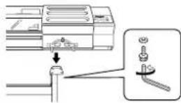
Use the joining screws to secure the unit to the stand.
Failure to do so may result in falling of the unit, leading to injury.

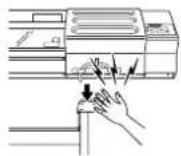
Use care to avoid pinching the fingers when placing the unit on the stand.
Doing so may result in injury.

Load roll media at the proper position.
Otherwise the roll may fall, resulting in injury.

natural_image
Simple line drawing of a cylindrical object with motion lines indicating force or motion (no text or symbols)
Do not touch the tip of the blade with your fingers.
Doing so may result in injury, and the cutting performance of the blade will be impaired.

natural_image
Line drawing of two hands gently holding a small object with droplets falling (no text or symbols)
Unpacking, and installation must be carried out by four or more persons.
Otherwise the machine or the stand may fall, resulting in injury.

natural_image
Illustration of workers in hard hats operating large cylindrical equipment (no text or symbols visible)
Install in a level and stable location.
Failure to do so may result in the unit tipping over, leading to injury.


Be sure to install the media guide when loading roll media.
Otherwise the roll may fall and cause injury.

natural_image
Simple line drawing of a cylindrical object with motion lines indicating movement (no text or symbols)
Release the caster locks for the stand before attempting to move.
Otherwise the unit may tip over and cause injury.


Do not touch the control panel while head cleaning or other cleaning is in progress.
The printing carriage may move and cause injury.

CAUTION

Do not touch the tip of the separating knife with your fingers.
Doing so may result in injury.


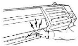
Do not place hands within the space to the front of the unit while in operation.
Doing so may result in injury.
natural_image
Line drawing of a hand holding a device with arrows indicating motion or force (no text or symbols)
Before switching on the power, be sure to install the drain bottle.
Otherwise discharged fluid may leak from the machine.
About the Labels Affixed to the Unit
These labels are affixed to the body of this product.
The following figure describes the location and content of these messages.

In addition to the ⚠WARNING and ⚠CAUTION symbols, the symbols shown below are also used

Notice formation to prevent machine breakdown or malfunction and ensure correct use.

iPoint handy tip or advice regarding use.
natural_image
Illustration of a hand using a tool to clean or store electrical outlets (no text or symbols present)

natural_image
Simple line drawing of a rolled roller being cut with motion lines indicating speed (no text or symbols)natural_image
Illustration of a hand using a power tool to spark electrical connections with stars (no text or symbols)
natural_image
Line drawing of workers handling large industrial equipment (no text or symbols visible)
natural_image
Simple line drawing of a rolled roller being compressed, with motion lines indicating compression or damage (no text or symbols)⚠️PRUDENCE

natural_image
Line drawing of two hands gently holding a small object with liquid droplets (no text or symbols)
natural_image
Line drawing of a hand holding a mechanical component with arrows indicating motion or force (no text or symbols)This section describes what to do when you first open the packing carton, including installing the machine and connecting it to a computer.
The following items are packed together with the unit. Make sure they are all present and accounted for.


Power cord : 1 Arm (Right) : 1 Arm (Left) : 1


Stand leg: 1


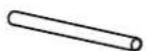
Washers: 6 Hexagonal wrench : 1 Pipe : 1

Media flanges : 2

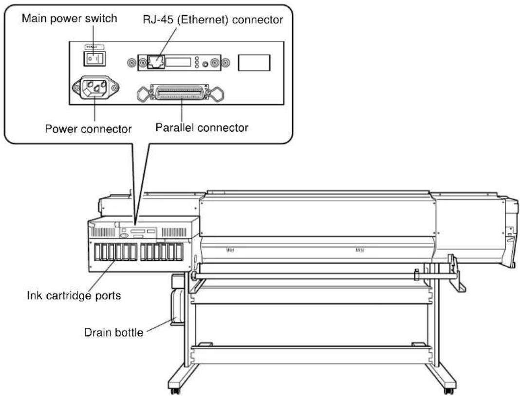
Rear View
Inside the Front Cover

Operation Panel
![[TEST PRINT] key [TEST CUT] key [CUT CONFIG] key [TEST PRINT] key [CLEANING] key [CUT CONFIG] key [MENU] key [ENTER] key Arrow keys [MENU] key [ENTER] key MENU CUT CONFIG CLEANING TEST CUT TEST PRINT DISPLAY BUSY AUTO ALIGN AUTO UP/DOWN BASE POINT ALIGN POINT AUTO ALIGN AUTO UP/DOWN SET UP PAUSE SHEET CUT POWER LED [POWER] key [ALIGN POINT] key [ALIGN POINT LED] [ALIGN POINT] key](/content/2026/06/1254103/images/405e2effe4cfc410fc1b451e996106d713de13509acf4a68dbaceb2880427ba7.jpg)

Do not operate in a location exposed to open flame, sparking, or static electricity, or in a location exposed to high temperatures, such as in the immediate vicinity of a heater. Also, do not place undried media in such locations.
Doing so may result in fire due to combustion of ink or cleaning liquid.

Ensure adequate ventilation for the work area.
Failure to do so may result in odor, physical distress, or fire.

Unpacking, and installation must be carried out by four or more persons.
Otherwise the machine or the stand may fall, resulting in injury.

Install in a level and stable location.
Otherwise the unit may tip over and cause injury.

Use care to avoid pinching the fingers when placing the unit on the stand.
Doing so may result in injury.

Use the joining bolts to secure the unit to the stand.
Failure to do so may result in falling of the unit, leading to injury.
Installation Environment

Notice
Never install the unit in any of the following situations, as it could result in breakdown or faulty operation:
- Places with excessive electrical noise.
- Places with excessive humidity or dust.
- Places with poor ventilation, because this machine generates considerable heat during operation.
- Places with excessive vibration.
- Places exposed to strong illumination or direct sunlight.
Never stand on the stand legs. Doing so may damage them.
Do not place objects on the unit, as doing so may result in breakdown.
The required installation spaces for this model is below.
Step 1: Assemble the Stand
First assemble the stand, then mount the machine on top of the stand.
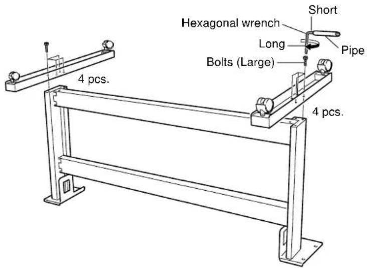
1 Invert the stand legs as shown in the figure. While supporting the stand legs with your hand, attach the left- and right-hand casters.

Point
Tighten the bolts securely. Loose bolts may cause the stand to wobble.
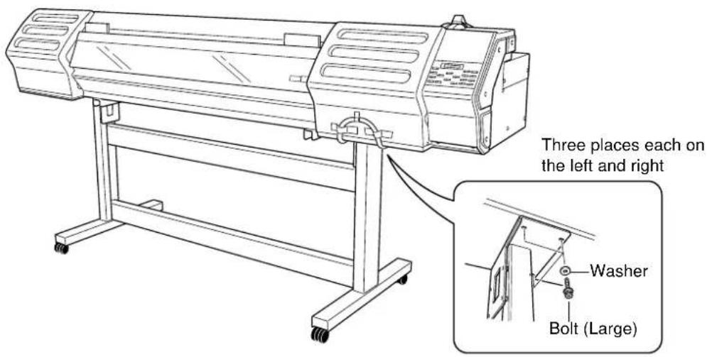
2 Set the stand upright so that the casters are at the bottom, and place the machine on the stand. The front and rear of the stand are as shown in the figure.

3 Use the included large bolts to secure the machine to the stand.
Step 2: Install the Included Items
1 Attach the arms onto the back of the machine at the locations shown in the figure.

2 Pass the stoppers onto both ends of the shaft. When passing the shaft through the stopper, be sure to loosen the screws on the stopper first.

3 Attach the two shafts and engage the brake. Install the shafts so that the one with the stopper is in front of the back of the machine.


Point
Make sure the shaft brake is engaged. Using the machine with the brake disengaged may result in unstable media feed, leading to poor image quality.
Step 3: Install the Drain Bottle

Point
Leave the drain bottle attached at all times, removing it only when moving the machine or disposing of collected ink.
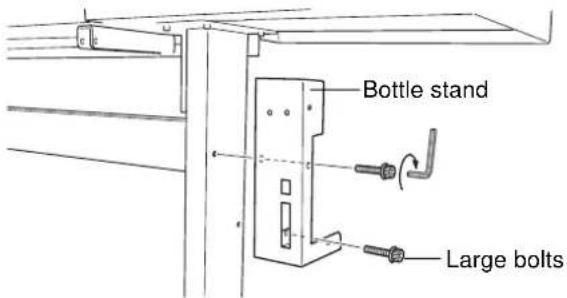
1 Use the included large bolts to secure the bottle stand in place.
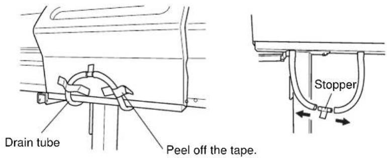
2 Remove the stopper from the drain tube.

Notice
When you remove the stopper from the drain tube, discharged fluid used in shipping inspection may be released from inside the tube. Exercise caution.
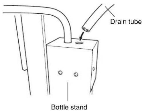
3 Insert the drain tube securely into the bottle stand.
4 Attach the drain bottle to the back of the machine.

natural_image
Diagram showing a device being inserted into a device, with an arrow indicating the process (no text or symbols present)
Point
Before you attach the drain bottle, make sure the lid and the inner cover inside the drain bottle have been removed.

Point
For more information about how to dispose of discharged ink.
"4-5 Disposing of Discharged Ink"

Step 4: Remove the Protective Media
The protective media shown below is attached to this machine when it is shipped from the factory. When you have finished installing the machine, remove all protective media.
Front

flowchart
graph TD
    A["Packing"] --> B["1) Remove packings."]
    B --> C["2) Peel off the tape."]
    C --> D["3) Peel off the tape, and remove the packing. (Pull straight back toward you to extract.)"]
    D --> E["4) Remove the retainer.6) Peel off the tape. 5"]
    E --> F["Point: If the screw for the retainer is difficult to loosen, use a screwdriver to remove it."]
Rear

7) Attach the retainer you removed in step 4).

Use only with a power supply of the same rating as indicated on the unit.
Use with any other power supply may lead to fire or electrocution.

Ground the unit with the ground wire.
Failure to do so may result in risk of electrical shock in the even of a mechanical problem.

Use only with the power cord included with this product.
Use with other than the included power cord may lead to fire or electrocution.
Connecting the Power Cord

Notice
Securely connect the power cord, computer I/O cable and so on so that they will not be unplugged and cause failure during operation. Doing so may lead to faulty operation or breakdown.
Before connecting the cable, make sure the computer's power and the main power switch of the unit are switched off.
Arrange the power cord and interface connection cable to prevent tripping when moving around the unit.

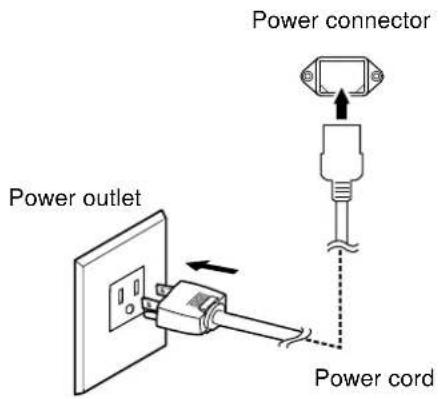
Connecting to the Computer

Ethernet Connection
RJ-45 (Ethernet) connector

Various settings are required when using this machine in a network environment. For more information, see the “Roland PrintServer Network Settings Guide”.

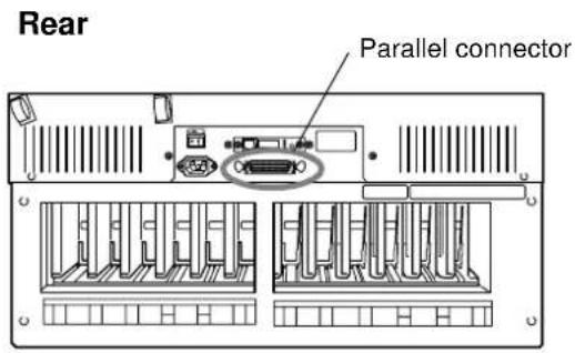
Connection to a Parallel Connector
When making the connection to the computer using a printer cable, connect the printer cable at the position shown in the figure.
* Cables are available separately. One which you are sure matches the model of computer being used should be selected.
Securing the Cable

Notice
Pass the cable through the established location, making sure that it does not touch the loaded media. If the cable touches the media during printing, media feed may be obstructed, resulting in poor printing accuracy.

Step 1: Install Ink Cartridges

Store ink cartridges out of the reach of children.

If ink or cleaning liquid comes in contact with the eyes, immediately flush with running water for at least 15 minutes.

Notice
If an ink cartridge is dropped, the shock due to the fall may damage the ink cartridge and make it unusable.
When installing and removing an ink cartridge, do not rush. Detach the cartridge gently. Sudden movement when detaching may cause ink to be spilled.
Use only SOL INK. Do not insert any other type of ink cartridge.
Confirming the Ink-insertion Sites


Filling Ink
Installing ink cartridges for the first time after purchase requires four SOL INK cleaning cartridges. This is also the case when you are draining ink in preparation for transport, then reinstalling the ink cartridges.
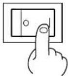
1 Switch on the main power on the back of the machine.
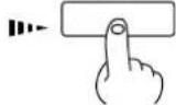
2 Press the [POWER] key on the operation panel.
3 Check the type of ink to install, then press the [ENTER] key.
4 Follow the messages to make sure the drain bottle is installed at the back of the machine.
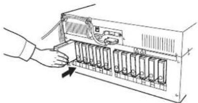
5 Insert cleaning cartridges into the ink-cartridge ports shown by flashing on the display. Insert the four cartridges firmly, as far as they will go.
Cleaning starts. The cartridges are inserted and removed while the operation is in progress. Follow the messages on the display to carry out the procedure. Cleaning may take some time.
6 When cleaning ends, the following message appears. Follow the instructions given in the message to remove the cleaning cartridges.
Finishing all cleaning, return step 5 and step 6.
7 Firmly insert the SOL INK cartridges for each of the colors as far as they will go.
Ink filling starts.
SELECT INK TYPE SOL INK LcLm
INSTALL DRAIN BOTTLE
SET SOL CL - LIQUID 1 2 3 4 5 6 7 8 9 10 11 12
REMOVE SOL CL 1 2 3 4 5 6 7 8 9 10 11 12
SET SOL CRT. 1 2 3 4 5 6 7 8 9 10 11 12
natural_image
Line drawing of a hand inserting a device into a rack with multiple ports (no text or symbols)8 After ink filling has finished, empty the drain bottle and press the [ENTER] key.

Point
For more information about how to dispose of discharged ink, see "4-5 Disposing of Discharged Ink."
Step 2 : Match the Machine to the Environment Where Installed
The machine performs automatic adjustment to optimize its state to the environment where it is used (temperature and humidity).
Performing automatic adjustment reduces misalignment in the scanning direction (the direction of movement of the carriage) during printing and cutting.
1 Press the [MENU] key, and press the [▼] key to make the following screen appear on the display.

2 Press the [ENTER] key.
When material is loaded, the message shown in the figure appears. Remove the material, then press the [ENTER] key again.
The printing carriage moves and the printing length in the carriage-movement direction is adjusted.

3 When automatic adjustment ends, the screen returns to the display in step 1.

Do not touch the tip of the blade with your fingers.
Doing so may result in injury, and the cutting performance of the blade will be impaired.

Notice
Do not leave the tool mounting screws tightened. Tightening the screw makes it more difficult to install the blade holder.
Installing a Blade
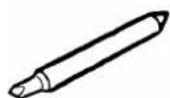
1 Insert a blade into the blade holder until it snaps into place with an audible click.
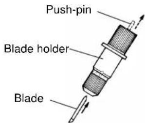
2 Adjust the amount of blade extension as shown in figure to find the optimal amount of blade for the target material.

3 Press the [MENU] key, and press the [▼] key to make the following screen appear on the display.

4 Press the [ENTER] key to make the following screen appear on the display.

When the screen shown in the figure appears, the printing carriage simultaneously moves to the left.
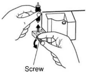
5 Open the front cover, loosen the screw in the figure.

6 Support the tool-securing screw from below and install the blade holder.

Notice
When cutting is performed after printing, the cap tip of the blade holder may scratch the printed surface. If this is the case, lengthen the cutter blade extension.
Insert the blade holder until the collar is flush with the carriage.
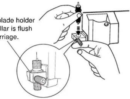
7 Tighten the screw.
Tug the blade holder upward to make sure it does not come loose.
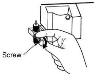
8 Close the front cover, and press the [ENTER] key.
Removing a Blade
1 Press the [MENU] key, and press the [▼] key to make the following screen appear on the display.

2 Press the [ENTER] key to make the following screen appear on the display.
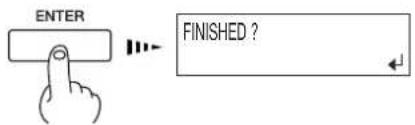
When the screen shown in the figure appears, the printing carriage simultaneously moves to the left.
3 Open the front cover, loosen the screw in the figure, and remove the blade holder from the cutting carriage.
natural_image
Illustration of hands using a screw to adjust a mechanical component (no text or symbols)4 Remove the blade.

Press the push-pin
5 Close the front cover, and press the [ENTER] key.
2. Basic Operation
This describes the sequence of basic operations from switching on the power to performing printing or cutting.
2-1 Examples of Operations with This Machine
You can perform a wide variety of operations with this machine. For example, you can perform only printing, perform only cutting, or perform printing and cutting, or even perform printing, then remove the media, laminate it, and then cut it.
The results of operations such as printing only or cutting only differ depending on the settings used to send the data from the raster image processor (RIP). For information on how to make the RIP settings, refer to the documentation for the RIP you're using.
For detailed information about the different operations, refer to the following sections of this manual.
- Performing printing only "2-4 Printing"
- Performing cutting only ☐ "2-5 Cutting"
- Performing printing and cutting "2-6 Printing and Cutting"
- Removing the media after printing, then reloading it and performing cutting "2-7 Reloading the Media and Performing Cutting"
Switching On the Power
Leave the main power switch turned on, and use the [POWER] key to switch the power on and off in day-to-day use.


Notice
Points to Keep in Mind When Switching the Power On and Off
Do not switch off the main power while the sub power is switched on. The printing heads may be left uncapped (that is, the printing carriage may remain over the platen). If the machine is allow to stand to with the printing heads uncapped for a prolonged period, the printing heads may become irreversibly clogged.
Before switching off the main power, be sure to hold down the [POWER] key for one second or longer to switch off the sub power.
If the printing carriage stops while over the platen, press the [POWER] key to reset the power. The printing carriage moves and the printing heads are capped.
If the printing carriage does not move even when you reset the power using the [POWER] key, refer to "6-1 What to Do If --What to Do When the Printing Carriage Does Not Move."
Switching Off the Power at the End of the Day
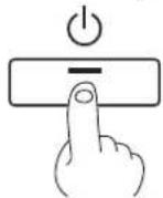
Press and hold down the [POWER] key for one second or longer to switch off the sub power.
The POWER LED goes out

Notice
Leave the pinch rollers raised when not in use. Deformation may occur if left lowered for a prolonged period.


Be sure to install the media guide when loading roll media.
Otherwise the roll may fall and cause injury.

Load roll media at the proper position.
Otherwise the roll may fall, resulting in injury.

Notice
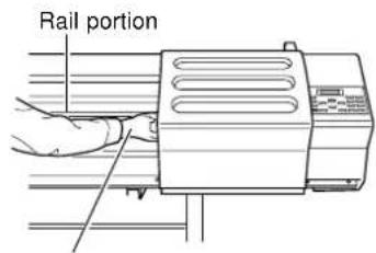
Do not touch the rail or the inner side of the left and right cover. Touching the area shown may cause the fingers to be soiled by grease or ink, and may result in diminished image quality.
Do not put hands inside
Loading Roll Media
1 Open the front cover.
2 Move the media clamps to the left side of the platen.

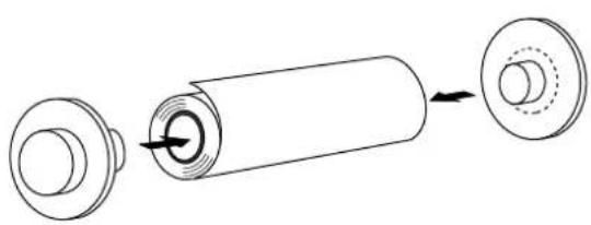
3 Align the media flange with the roll media edges, matching the roll media center ID.
natural_image
Diagram of a cylindrical battery with internal components and an external housing (no text or symbols)
Continued on the next page
4 Place the rolled media on the shaft.
Pass the end of the media between the pinch rollers and the grit rollers so that it extends from the front of the unit.
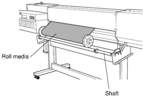
5 When viewed from the front, align so that the left-hand edge of the media is above any of the grit rollers and the right-hand edge is above any of the three grit rollers of the right side of the main unit.
Align the media so that it is straight, and move pinch rollers so that they are above the grit rollers. And position the left and right pinch rollers at the two edges of the media. Position one (or both) middle pinch rollers so as to form equally spaced intervals along the width of the media.
The positions of the pinch rollers change according to the size of the media that is loaded. Refer to "7-2 Media Conditions -- Acceptable Media Width."


Point
Using the Middle Pinch Rollers
Use the middle pinch rollers as required. When a wide media is loaded, using the middle pinch rollers keeps media feed stable.
When using : Position it over the grit rollers.
When not using: Move it to a position away from the grit rollers. When in this state, the media is not clamped even when the sheet loading lever is lowered.
6 Align the left- and right-hand stoppers with the width of the media and tighten the screws to secure in place.

7 Pull out the media so that at least 50 cm (20 in.) hangs down at the front of the machine.
8 Rotate the media flanges on the shaft to take up the hanging media at the front of the machine.
To ensure that the media take-up is not crooked, clear of items such as the media clamps that may obstruct media feed.

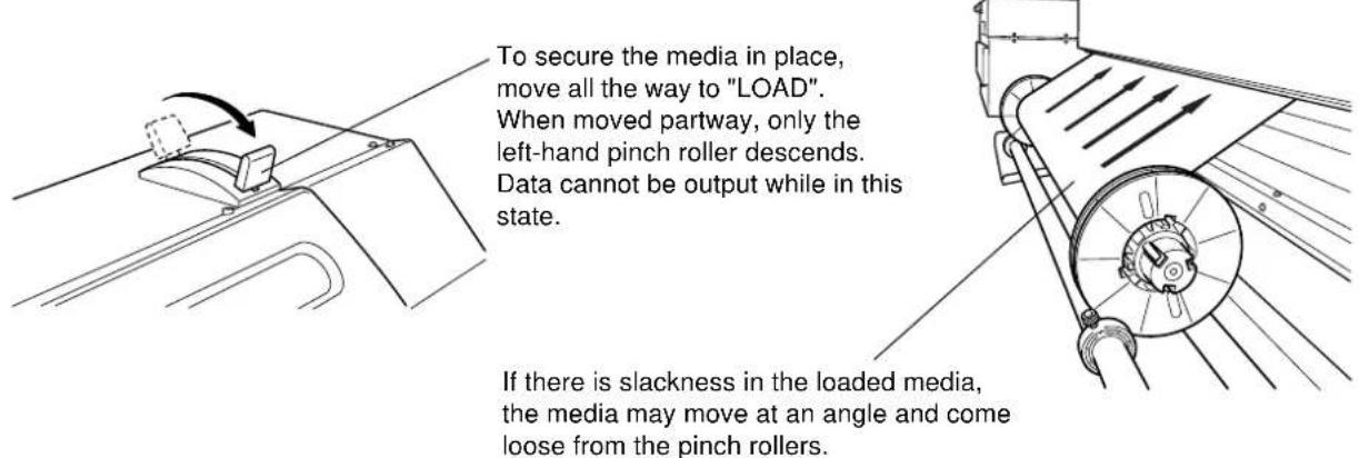
9 With the media pulled out from the roll stretched taut with no slack, move the sheet loading lever toward "LOAD".
Pinch rollers lower to hold the media in place.
Continued on the next page
10 Close the front cover.
Use the [▶] and [ ] keys to select [ROLL], then press the [ENTER] key.
SETUP SHEET ROLL EDGE PIECE

Point
If cutting is to be performed from the edge of the media, select [EDGE] (If [EDGE] does not appear, set [EDGE SENSE] to [ENABLE]).
11 Press the [SETUP] key.
This detects the width of the media and displays the printable width.
The SETUP LED lights up

If a pinch roller is positioned over an area where is no grit roller, the message shown at below appears when you press the [SETUP] key. Check the positioning of the pinch rollers and make sure they are aligned at the correct positions.
![ROLAND SC-540 - Press the [SETUP] key. - 2](/content/2026/06/1254103/images/1052ae899e7c37b50ac3c4fa851b798a32d3601eddf180ea45b3f47bca86a818.jpg)
![ROLAND SC-540 - Press the [SETUP] key. - 3](/content/2026/06/1254103/images/b1b23be4850ec2af0f94accab9ebb2784e54d92eece5c4a842e9eb9ced532917.jpg)
Notice
When the machine will remain unused for an extended period, remove roll media from the machine and store it. If roll media is left mounted on the machine for an extended period, these entire roll may warp, resulting in poor printed image quality or motor errors.
Loading Sheet Media
Before attempting to load sheet media, check the following points.
Front View
Align the front edge of the media with the location shown in the figure.
Front

Rear View
Remove the shaft and roll media at the back of the unit.
Displaying Menu
Use the [▶] and [◀] keys to select [PIECE], then press the [ENTER] key.
SETUP SHEET
ROLL EDGE PIECE
When Loading Thick Media (Only When Printing)
Media that is thick or that warps easily may lead to problems with media feed or jamming. When you are using such media, adjust the height of the printing heads. You adjust the height of the printing heads only when performing printing.

Point
When the height of the printing head has been adjusted, it is necessary to perform bidirectional correction. For more information about bidirectional correction, see "3-6 Making Corrections for Printing -- Bidirectional Correction."
For more information about the thicknesses of media that you can load, see "7-2 Media Conditions."
Adjusting the Head Height
The head height is setting at position 2 (middle) when shipped from the factory.
1 Open the front cover.
2 Press the [MENU] key, and press the [▼] key to display the screen shown in the figure.
3 Press the [▶]key to display the screen shown in the figure.
When the screen shown in the figure appears, the printing carriage simultaneously moves to the left.
4 Move the lever to adjust the height of the head.
When you move the lever, the machine beeps and the screen display changes.
- When the lever is moved to position 1 (low): One beep
- When the lever is moved to position 2 (middle): Two beeps
- When the lever is moved to position 3 (high): Three beeps

Point
Move the lever until it stops. If it is not at position 1, position 2 or position 3, bidirectional printing may be misaligned.


3 (high) : When media that is thick or prone to warping is loaded
2 (middle) : Standard
1 (low) : Suitable for high image quality
5 Close the front cover. The printing carriage return to the standby position.
When Loading Media That Warps Easily (Only When Printing)
When you are loading media whose left and right edges are prone to warping, use the media clamps. The media clamps can be used to secure media that is up to 0.7 mm (0.027 in.) or so in thickness.

Notice
The following media cannot be used even when secured in place by the media clamps.
• Media whose warping is not corrected by securing it in place
• Media that deforms the media clamps when it is secured in place
• Media that is prone to warping and that has a thickness of 0.7 to 1 mm (0.027 to 0.039 in.)
• Media with a strong tendency to curl
Attempting to force such media to be loaded may result in malfunction.
Do not use the media clamps during cutting. Doing so may damage the equipment.
Do not use the media clamps when performing printing with the height of the printing heads set at position 1. The media clamps may scrape the printing heads.
Securing in Place Using the Media Clamps
1 Position the printing heads at 2 (middle) or 3 (high).
2 With your finger, lightly press down on each media clamp at the location shown in the figure to move it and make it grip the media.
3 Line up the holes in the media clamps with the left and right edges of the media.

Point
Set the media clamps at the correct locations. If they are not set at the correct locations, the media may catch or cause other problems.

natural_image
Illustration of a hand using a tool to adjust or install a mechanical component (no text or symbols visible)

Notice
When you cut off media while using the media clamps, then depending on the media, it may come loose from the media clamps. After you cut off the media, check to make sure that the media has not come loose from the media clamps.
As printing proceeds, the media may move to the left right and touch or come loose from the media clamps. After about 1 m (3 ft.) of media has been fed, check the positioning of the media clamps. If the media looks like it may come loose from the media clamps, adjust the positioning of the media clamps.
The media clamps are designed to press down on a space 10 mm (7/16 in.) inward from either edge of the media. Do not perform printing within these areas.
Separating the Media
Make sure the [SETUP] LED lights up.
To cut off a printed portion from the roll, hold down the [SHEET CUT] key for at least one second. The piece is cut off at the present location of the printing-start line. This step is not necessary when cutoff is performed automatically by sending a media-cutoff command from the computer.

Point
Depending on the composition of the media, cutoff may not be possible.
Depending on the composition of the media, media may remain on the platen after cutoff. If this happens, remove it by hand.
When you're performing cutoff, do not use the [▲] key to pull the media back. Unless the end of the media has been pulled out to a location to the front of the platen, cutoff may not be performed smoothly.

Removing the Media
1 Refer to the previous section, "Separating the Media," and cut off the media.
2 When the SETUP LED is lighted, hold down the [SETUP] key for at least one second.
3 Move the sheet loading lever toward the back of the unit.
The pinch rollers rise to release the media.
4 Remove the media.
The SETUP LED goes out
Sheet loading lever

natural_image
Technical line drawing of a mechanical component with a tool and curved base (no text or symbols)
Notice
Do not open the front cover. Opening the front cover while printing is in progress causes an emergency stop. This means that printing may not be carried out correctly even if operation is resumed, due to drop-out or misalignment of the image.
During printing, do not touch the portion of the media that's already been discharged.
Doing so may obstruct media feed or cause the media to rub against the heads, which may result in a paper jam or damage to the heads.
The printing heads may be left uncapped (that is, the printing carriage may remain over the platen). If the machine is allow to stand to with the printing heads uncapped for a prolonged period, the printing heads may become irreversibly clogged.
If the printing carriage stops while over the platen, press the [POWER] key to reset the power. The printing carriage moves and the printing heads are capped.
If the printing carriage does not move even when you reset the power using the [POWER] key, refer to "6-1 What to Do If -- What to Do When the Printing Carriage Does Not Move."
To Perform Printing
Before performing a printing test or starting printing, make sure the following two points have been carried out.
- Media is loaded and the front cover is closed.
- The SETUP LED is illuminated.
Pressing the [SETUP] key detects the width of the media and displays the printable width.

Point
How to Load Media
For information on how to load media, refer to "2-3 Loading Media."
The [SETUP] Key
Pressing this for one second or longer clears the media setup.
If another menu screen is displayed, the media setup is not cleared simply by pressing the [SETUP] key.
Performing a Printing Test
Before starting to print, carry out a Test print to check the state of the head.
Problems such as missing dots may reduce the printing quality.
If the test results show a problem, carry out head cleaning to restore the head to its normal state.
1 Press and hold the [TEST PRINT] key for at least one second to carry out a printing test. The test pattern is printed.

2 If dot drop-out is present, clean the heads. For more information about head cleaning, see "4-1 Cleaning the Printing Heads."

Downloading Printing Data
Printing is started when data is sent.
If the top menu isn't displayed, printing doesn't start even when data is sent from the computer. If another menu screen is displayed, press the [SETUP] key, and display the top menu.

Point
Conditions for starting printing
- The media must be already set up (with the SETUP LED lighted).
- The display must show the top menu.
Top menu
W 1234 mm L ---- mm

Notice
Do not open the front cover. Opening the front cover while cutting is in progress causes an emergency stop. This means that printing may not be carried out correctly even if operation is resumed, due to drop-out or misalignment of the image.
Do not use the media clamps during cutting.
To Perform Cutting
If you're using roll media, then before you start cutting, leave media hanging freely at the rear. Turn the media flanges by hand to pull out the necessary length from the roll. If cutting is started without doing this first, a motor error may occur or the roll may fall because the media is pulled with excessive force.
Also, before performing a cutting test or starting cutting, make sure the following two points have been carried out.
- Media is loaded, a blade is installed, and the front cover is closed.
- The SETUP LED is illuminated.
Pressing the [SETUP] key detects the width of the media and displays the printable width.

Point
How to Load Media
For information on how to load media, refer to "2-3 Loading Media."
The [SETUP] Key
Pressing this for one second or longer clears the media setup. If another menu screen is displayed, the media setup is not cleared simply by pressing the [SETUP] key.
Test Cutting
Cutting quality is affected by the blade and media being used, and by the cutting conditions. There are four cutting conditions: "cutting speed", "blade force", "blade offset", and "amount of blade extension". For high-quality cutting, it is necessary to set the appropriate cutting conditions for the blade and media in actual use.
The cutting test is a feature for checking beforehand whether these cutting conditions are appropriate.
1 Install a blade and load a media, then close the front cover. Make sure the [SETUP] LED lights up.
2 Use the [▲], [▼, [ ] and [ ] keys to move the tool carriage to the place where the test cutting is to be performed.
3 Press the [TEST CUT] key for 1 second or longer. Test cutting starts.
4 Examine the cutting results for the media and diagnose the cutting conditions.

natural_image
Simple geometric diagram with a square inside a circle and two lines extending outward (no text or symbols)(1) Peel off the round section (marked by ).
→ When it can be peeled by itself, without disturbing the square (marked by ), the cutter force is set appropriately.
If it peels, either the "blade force" or the "amount of blade extension" is insufficient.
(2) Remove the square section (marked by 0). The optimum blade pressure is correct if you can clearly make out the lines left by the blade. If the blade trace is indistinct or too strong, you need to adjust the "blade force" or the "amount of blade extension".
(3) Check the shape of the rectangle.
- If the corners are cut securely as shown in A, there conditions are correct.
- If the corners are rounded as shown in B, the "blade offset" is insufficient.
- If the corners have "horns" as shown in C, the "blade offset" is too large
A

B

C

If the test cutting shows problems with the media cutting results, adjust the cutting conditions.
For "cutting speed", "blade force", and "blade offset", press the [CUT CONFIG] key and set the cutting conditions.
(Refer to "5-1 Display Menus Flowchart")
For "amount of blade extension", refer to "1-6 Installing the Blade".
Repeat the cutting tests and adjustment of the cutting conditions until you obtain good cutting results for the media.

Point
When [CUTTING PRIOR] on the machine's display menu has been set to [COMMAND], the program's settings for the cutting conditions take priority.
To give priority to the cutting conditions set on the machine, turn off the program settings, or set the [CUTTING PRIOR] menu to [MENU].
For more information about the [CUTTING PRIOR] menu, see the section "5-2 Description of Menus".
Incorrect cutting conditions may cause symptoms such as those described below.

• The material is easily torn.
• The cutter requires frequency replacement.
- Cutting extends through the base paper, and normal advancing of the material becomes impossible.
• The unit suffers damage.
Some parts of the material remain uncut.

Point
If you are using a media with a strong adhesive layer, the adhesive layer may adhere to itself immediately when cut. This means that even though the media has actually been cut, it may appear as if it has not been cut, and blade force may mistakenly be set too high.
If a cutting test shows that the media peels easily and the blade traces on the carrier paper are optimal, then the media is being cut. Take care not to set the blade force excessively high.
Downloading Cutting Data
Cutting is started when data is sent.
If the top menu isn't displayed, cutting doesn't start even when data is sent from the computer. If another menu screen is displayed, press the [SETUP] key, and display the top menu.

Point
Conditions for starting printing
- The media and blade must be already set up (with the SETUP LED lighted).
• The display must show the top menu.
Top menu
W 1234 mm L ---- mm
You can perform printing and cutting at the same time. You send the data, perform printing, and after printing has finished, you start cutting. Before you send the data, make sure a blade is installed in the cutting carriage.
Sequence of Operation for Printing and Cutting
Step 1: Perform Printing

Step 2: Dry the Media

Before you start cutting, allow the media to dry sufficiently. (The drying time varies according to the type of media.) If the media is not dry enough, the pinch rollers or the blade may smudge the printed surface during cutting.
Setting the drying time on the RIP you're using lets you start cutting after waiting for a fixed interval. For information on how to make the setting, refer to the documentation for the RIP you're using.
Step 3: Perform Cutting
Do not use the media clamps when cutting.
When you perform printing followed by cutting, the end of the cap for the blade holder may rub against and damage the printed surface. (Damage is even more likely when drying is insufficient.)
If this happens, increase the amount of extension of the blade tip slightly.
If the media is not dry enough, using the middle pinch roller may smudge the printed surface. For more information about the usage of the middle pinch roller, see "2-3 Loading Media."
When you are performing printing, then performing lamination or the like, reloading the media, and performing cutting, using the alignment function makes it possible to align the printing and cutting positions.
Alignment of the printing and cutting positions uses crop marks. Printing with crop marks added enables automatic detection of the crop marks during cutting, thereby making alignment possible.
Printing Area
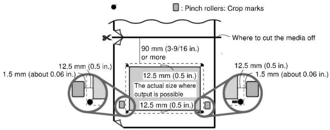
When you print with crop marks, the area that you can print or cut is reduced by an amount corresponding to the size of the crop marks.
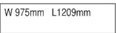
You can easily check the actual size of the area where output is possible without crop marks. While the display shows the area where output is possible, press and hold the [ENTER] key. The actual size where output is possible is displayed until you release the key.
Printing or cutting area of the entire piece of media
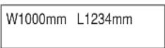

Printing or cutting area without crop marks


Point
When you're printing with crop marks, attempting printing that exceeds the size of the area where output is possible or that conversely is too small (40 mm (1-5/8 in.) [scanning direction] X 15 mm (5/8 in.) [feed direction]) results in the message shown in the figure, and operation pauses.
To quit printing, stop sending data from the computer and press the [SETUP] key. Pressing the [ENTER] key starts printing, but the portion that exceeds the size where output is possible is truncated and crop marks are not printed.
CAN'T PRINT CROP CONTINUE?

Media Sizes Allowing Automatic Crop-mark Detection
When you are printing with crop marks, set a margin of at least 90 mm (3-9/16 in.) before the next print-start position. You can set the margin value with the RIP you're using. For information on how to make the setting, refer to the documentation for the RIP you're using.
Printing with Crop Marks
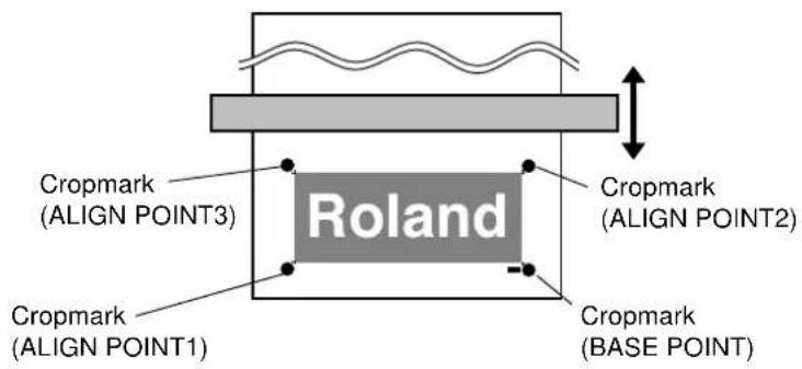
Load media and output the data. Crop marks are automatically printed at four places.
Use your RIP to make the setting for printing crop marks. For information on how to make the setting, refer to the documentation for the RIP you're using.
You can use BASE POINT and ALIGN POINT 1 through ALIGN POINT 3 to perform alignment automatically or manually. For information about how to make the settings, see the following section.

Point
Crop marks and the like drawn with computer programs cannot be used as crop marks by this machine.
Aligning Automatically
Read the four crop marks and perform alignment for printing and cutting.
1 Reload the media. Press the [SETUP] key to display the top screen.
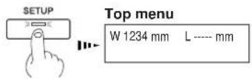

Alignment cannot be performed if the line connecting the left and right crop marks is slanted by 5 degrees or more. Adjust the positioning of the loaded media.

2 Move the center of the blade to a position over the lower-right crop mark (the base point), then press the [AUTO ALIGN] key.
The screen shown in the figure appears.

3 Use the [▲] and [▼] keys to choose [BASE ALIGN], then press the [ENTER] key.
The four crop marks are read automatically. After the reading operation has finished, a beep sounds.

4 Send the cutting data.
Cutting starts.

Point
In the automatic-detection operation, media feed continues until crop marks are detected. If the crop marks could not be detected automatically, follow the steps below.
Stopping Operation Manually
- Press the [PAUSE] key. The screen shown in the figure appears.
- Press the [ENTER] key.
Auto-stop Feature
If crop marks are not detected after 3 m (9.8 ft.) of media have been fed out, detection is paused and the screen shown in the figure is displayed. If you want to quit detection, press the [ENTER] key. If you want to output something that is 3 m (9.8 ft.) or longer, then press the [PAUSE] key to continue detection.

If you're using dye-based inks, Aligning Automatically is not possible. Follow the steps in "Aligning Manually" on the next page.
Aligning Manually
Depending on the type of media, it may not be possible to detect crop marks automatically. When crop marks cannot be detected automatically, you perform alignment manually.
1 Set the location of the origin point. Use [▲], [▼], [ ], and [ ] to move the center of the blade to above the lower-right crop mark. Use the [TOOL UP/DOWN] key to move the blade up and down and make sure it is positioned correctly.
Align the center of the blade with this location.

Center of the blade

2 Press the [BASE POINT] key. The location where the BASE POINT is set is displayed.
W1234mm L1000mm B
3 Use the [A, [V], and [ ] keys to align the center of the blade with any of the align points (ALIGN POINT 1 through ALIGN POINT 3), then press the [ALIGN POINT] key. The location where the ALIGN POINT is set is displayed. You can also set more than one ALIGN POINT.


This screen shows BASE POINT and ALIGN POINT1 is setting.

Point
You can set up to three align points. Change the number of points set with [ALIGN POINT] as required.
The locations on the media of ALIGN POINT 1 through ALIGN POINT 3 are fixed. The machine automatically determines from the location of the BASE POINT which ALIGN POINT or points have been set. The screen display the number of each ALIGN POINT that has been set. For information about the location of ALIGN POINTS, see the previous section, "Printing with Crop Marks."

Set the align points after you set the BASE POINT. Setting the BASE POINT after setting ALIGN POINTS clears all the previously set ALIGN POINTS.
3. A Wide Variety of Operations
This section describes a wide variety of operations and functions, grouped by task.
Care and Handling of Ink Cartridges

Notice
- Do not use anything other SOL INK cartridge. Do not attempt to refill and reuse an empty ink cartridge.
- Do not attempt to disassemble an ink cartridge.
- If an ink cartridge is dropped, the shock due to the fall may damage the ink cartridge and make it unusable.
- Store ink cartridges unopened at a temperature of -20^ (-4^) to 40^ (104^) in a well-ventilated location.
- Do not remove any ink cartridges except when shipping the machine.
- Do not allow a removed ink cartridge to sit out for any length of time. Doing so may result in clogging of the heads.
- Use only the type of filled ink specified for the machine.
- If ink runs out, replace immediately with an ink cartridge designed especially for the machine.
- Do not attempt to refill and reuse an empty ink cartridge. If an ink cartridge is removed, replace it immediately with a new one.
- When removing an ink cartridge, do not rush. Detach the cartridge gently. Sudden movement when detaching may cause ink to be spilled.
- Once an ink cartridge has been installed, do not remove it until the ink has been used up. Frequent insertion and removal may allow air to enter the ink tube and result in a drop in printing quality due to dot drop-out or the like.
Replacing with New Ink Cartridges
Replacing an Ink Cartridge
Before you attempt to replace an ink cartridge, check the following two points.
• The machine is switched on.
• Operation is stopped or paused.

Removing or inserting an ink cartridge while operation is in progress may cause air to get inside the cartridge, resulting in poor image quality.
1 Remove the ink cartridge from the ink-cartridge port.

2 Insert new ink cartridge.

Be sure to use genuine SOL INK cartridges from Roland DG Corp. Installing other types of ink may result in breakdown or faulty operation.
If Ink Runs Out During Printing
If ink runs out during printing, a warning beep sounds and the screen shown in the figure appears.
Replace the ink cartridge. Ignoring the message and continuing printing without replacing the ink may adversely affect image quality, resulting in faintness or other problems.

The "____" for the ink that has run out flashes. The number indicates the number of the ink cartridge.
The flashed number indicate the ink cartridges at the locations shown in the figure.

Replacing Ink (When Set to the [STOP] Mode)
1 Pull out the ink cartridge indicated by the flashing number on the display.
2 Install a new ink cartridge.
![ROLAND SC-540 - Replacing Ink (When Set to the [STOP] Mode) - 1](/content/2026/06/1254103/images/fc943b84da69ca02df3b3c1f648fea9664bc7b65268cf627dc0ddd9da699660f.jpg)
Point
The behavior that occurs when it becomes necessary to replace ink while printing is in progress differs according to whether the selection for [EMPTY MODE] under [INK CONTROL] is set to [CONT.] or to [STOP]. (The default setting is [STOP].)
When Set to [STOP] (Pause)
[STOP] causes operation to pause immediately when ink needs to be replaced. Operation resumes when ink is replaced. Note, however, that the colors of an image in progress may no longer match perfectly if the unit is allowed to remain paused for two or three hours before resuming printing.
When Set to [CONT.] (Continue Printing)
Select this when ink cannot be replaced immediately while printing in progress, such as during unattended operation at night. When the machine is set to [CONT.], an alarm sounds approximately 1 m^2 before ink runs out, but printing continues without pausing. Because printing continues with only a small amount or remaining ink, the printed ink may be faint. As a general guide, about 1 m^2 of printing is possible with the remaining ink, but the amount of ink used varies greatly depending on the image. Printing can be continued only for the data for which printing is currently in progress. The machine stops when it finishes outputting one image.
You can use [INK REMAINING] on the display menu to check how much ink is left after the ink cartridges have been installed.
Use this information as a guide for replacing the ink cartridges.
![ROLAND SC-540 - When Set to [CONT.] (Continue Printing) - 1](/content/2026/06/1254103/images/62da50a8238490edabd46bfe71c800bab0f189416a4f1ce9fe47bda35dbf3728.jpg)
Point
In situations such as the following, the installed ink cartridge is taken to be an unused cartridge and the default amount of remaining ink is displayed, which does not match the actual amount of ink remaining.
- When an ink cartridge is removed and reinstalled while printing is in progress
- When a partly used ink cartridge is installed
1 Press the [MENU] key, and press the [▼] key to make the following screen appear on the display.

2 Press the [▶] key to make the following screen appear on the display.
You can check the amount of remaining ink for ink cartridges 1 through 8.

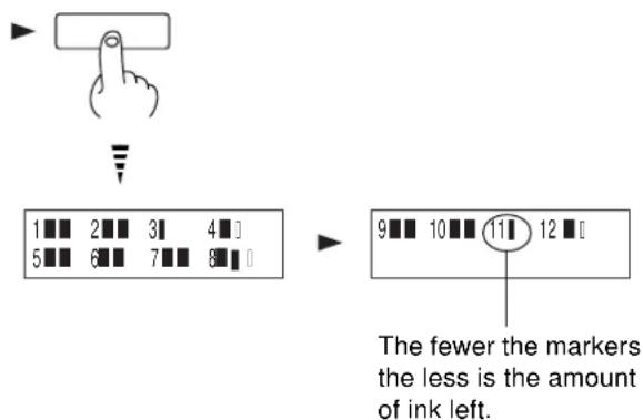
3 Continuing by pressing the [▼] key lets you check the amount of remaining ink for ink cartridges 9 through 12.
Setting the Start Location
Set the location where printing or cutting starts at the desired place.
[▲], [▼], [▶], and [◀] keys and the [BASE POINT] key to set the start points (origin points) for the feed direction (the direction of forward and backward movement) and the scan direction (the direction of movement of the printing carriage).


Point
When using [BASE POINT] key to change the print-start location, check the size of the data to print before you set the start position.
Setting the Start Location
1 Load media and install a blade, then press the [SETUP] key.
2 Use the arrow keys to align the blade with the new printing or cutting start location (base point).
3 Press the [BASE POINT] key. The display in the figure appears.

The BASE POINT LED lights up

W1234mm L1000mm B

Notice
When printing, do not use the | ▲ | key as much as possible to pulling back the media. Otherwise the following may occur.
- The pinch rollers may pass over the printed surface and smudge the ink.
- The grit rollers may leave tracks on the media, reducing printing accuracy.
- Printing may sag.

Point
When the Start Location Is Specified Using [ ▲ and [ ] Keys
When the operation is performed using only the [▲] and [▼] keys, the cutting carriage comes to a stop inside the cover. Pressing the [BASE POINT] key while in this state sets just the start position for the feed direction (the direction of front-to-back movement). For the scanning direction (the direction of carriage movement), the setting is made at the edge of the printing area.
![ROLAND SC-540 - When the Start Location Is Specified Using [ ▲ and [ ] Keys - 1](/content/2026/06/1254103/images/b4c006a4917e6219877bffab010e897efb443632398fe2425e6d6b879fddb98b.jpg)
To release the setting
The position setting by [BASE POINT] key is released such as the following.
- When printing, cutting, or printing and cutting for one page finish
- Press the [SETUP] key to cancel the setup for the media
Setting the Margins in the Feed Direction
You can set the margins in the feed direction using the software RIP (raster image processor). For information about how to make the settings for the margins, refer to the documentation for the RIP you're using.


Point
When a media-cutoff command is sent from the computer during continuous output, the value for the margin between the first printing and the next printing differs. For more information about margins, see "7-4 The Media-cutoff Location During Continuous Printing."
Feed Correction
This corrects for errors in the amount of feed of the grit rollers due the type of media. Be sure to make this setting when you have replaced the media with a different type. Correcting the amount of feed improves the dot-positioning accuracy in the feed direction, which can help enhance image quality.

Point
When correcting the amount of feed, set the same conditions for the type of media used and the configuration of the media (roll media or sheet media) as when actually performing printing.
When performing test printing for feed correction, load the media correctly (see "2-3 Loading Media"). If the media is not loaded correctly, an accurate correction value may not be output.
When you can set the error for the amount of feed for the grit rollers on the computer, the computer's setting takes priority. To make the machine's setting take priority, turn off the computer's setting.
Feed Correction
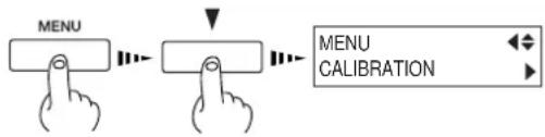
1 Press the [MENU] key, and press the [▼] key to make the following screen appear on the display.
2 Press the [▶] key to make the following screen appear on the display.
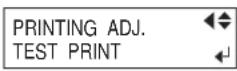
3 Press the [▶] key to make the following screen appear on the display.
4 Press the [ENTER] key to start printing a test pattern.
5 Press the [▼] key to make the following screen appear on the display.
6 Press the [▶] key to make the following screen appear on the display.
7 Use the [▲] and [▼] keys to set the value, then press the [ENTER] key.
Perform correction to ensure uniform dot spacing: If there are gaps in the test pattern, reduce the value. If there are overlapping areas in the test pattern, increase the value.


Correct


Overlapping areasGaps


Chapter 3 - A Wide Variety of Operations
Bidirectional Correction
This adjusts for misalignment that occurs during bidirectional printing. Perform adjustment for bidirectional correction in situations such as the following.
- When media is replaced with a different type
- When the head height has been adjusted
- When using in a location subject to large changes in temperature

Point
Bidirectional correction is enabled only when performing bidirectional printing.
Setting Adjustment Value
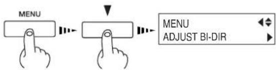
1 Press the [MENU] key, and press the [▼] key to make the following screen appear on the display.
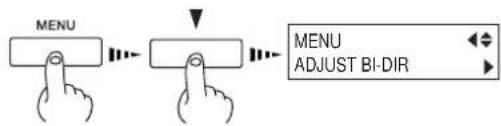
2 Press the [▶] key to make the following screen appear on the display.

3 Press the [ENTER] key to start printing a test pattern.
After the printing test has finished, the media is fed to a position that lets you to view the test pattern.
4 Check the test pattern and choose adjustment value (a value with no displacement).

5 Check the adjustment value, then press the [ENTER] key. The media returns to its position when the printing test ended.
6 Press the [▼] key to make the following screen appear on the display.
7 Press the [▶] key to make the following screen appear on the display.
8 Use the [◀] [ ]▶[ ] and [ ] keys to set the value you checked in step 4, then press the [ENTER] key.
In case of [SETTING NO.1], enter H1=71/2, H2=8, H3=7, H4=8, H5=6, and H6=7.
9 Use the [▲] and [▼] keys to Choose "Setting No.2". [SETTING NO. 2] appears. In the same way as in step 6 and step 8, enter the value you checked in step 4, then press the [ENTER] key.
Enter values in the same way for [SETTING NO. 3] and [SETTING NO. 4].

You can select from SETTING NO. 1 through SETTING NO. 4.


Saving and Loading a Bidirectional-correction Value
You can take adjustment values for bidirectional correction that you've set and save them in memory. You can save up to eight types.
Saving different adjustment values for different types of media lets you load the adjustment value simply and easily when you change the media type.
Saving an Adjustment Value
1 Follow the steps in the previous section, "Setting Adjustment Value," to enter adjustment values.
2 Press the [▼] key to make the following screen appear on the display.
3 Press the [▶] key to display the screen shown in the figure. Choose a number to save to from among [PRESETTING 1] through [PRESETTING 8], then press the [ENTER] key.
The adjustment values are saved in the memory number you selected.


Point
It may be a good idea to keep notes of the memory numbers and the kind of media whose adjustment value is saved in each number.
Loading an Adjustment Value
1 Press the [MENU] key, and press the [▼] key to make the following screen appear on the display.
flowchart
graph LR
    A["MENU"] --> B["Arrow pointing down"]
    B --> C["Arrow pointing up"]
    C --> D["Menu ADJUST BI-DIR"]
    style A fill:#f9f,stroke:#333
    style B fill:#ccf,stroke:#333
    style C fill:#cfc,stroke:#333
    style D fill:#fcc,stroke:#333
2 Press the [▶] key to make the following screen appear on the display.

3 Press the [▼] key to make the following screen appear on the display.

4 Press the [▶] key to display the screen shown in the figure. Choose the memory number to load, then press the [ENTER] key.

The selected adjustment value is loaded.

Point
This operation deletes adjustment values that are not saved in memory. If there are adjustment values that you want to keep, save them in memory first.
Environment Matching
If the machine's setting environment (temperature and humidity) changes, run the [ENV. MATCH] menu item to automatically adjust the machine to a state optimized to the environment where it is installed.
For more information about environment-matching procedures, see "1-5 Switching On the Power for the First Time -- Step 3: Match the Machine to the Environment Where Installed."
When printing is followed by cutting, the cutting line may be displaced from the printing margin. If this happens, use the [PRINT-CUT ADJ.] function on the menu to align the start points for printing and for cutting.

Point
Before you run [PRINT - CUT ADJ.], run [ENV. MATCH]. For more information about how to adjust this, see "1-5 Switching On the Power for the First Time -- Step 3: Match the Machine to the Environment Where Installed."
Adjusting Automatically
1 Load some media and press the [SETUP] key.
2 Press the [MENU] key, and press the [▼] key to make the following screen appear on the display.
3 Press the [▶] key to make the following screen appear on the display.
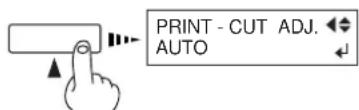
4 Press the [▲] key to make the following screen appear on the display.
5 Press the [ENTER] key to print crop marks and read the square mark automatically.
6 When the following message appears, automatic adjustment is finished.
The SETUP LED lights up



NOW PROCESSING...
While automatic adjustment is in progress, the following message appears on the display.
PRINT-CUT ADJ. COMPLETED!!

Point
Depending on the type of media, it may not be possible to perform correction automatically. If this happens, read in the offset value from a test pattern and align the positions for printing and cutting. For information on how to read an offset value from a test pattern, see the next section, "Adjusting Manually."
Adjusting Manually
Read the correction value from the test pattern printed and cut on the media. Enter the read correction value with the operation panel, then align the printing and cutting positions.
1 Load media and install a blade, then press the [SETUP] key.
The SETUP LED lights up

2 Press the [MENU] key, and press the [▼] key to make the following screen appear on the display.
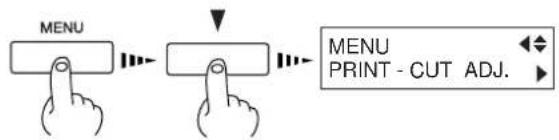
3 Press the [▶] key to make the following screen appear on the display.

4 Press the [ENTER] key to print and cut the test pattern.
![Test pattern and cut the test Make sure the value on the [SCAN] side. Correction-value scale Cutting line Make sure the value on the [FEED] side.](/content/2026/06/1254103/images/2a995be58959f205dc591fdc50cf7e955e2f86abf31b571fe4e2fb2dc0b27604.jpg)
5 From the test pattern, read the value at the location shown in the figure.

Read the scale on which the cutting line goes over as the correction-value.
In this figure, the value is "-0.3."
Use the same method to read the value on the [FEED] side.
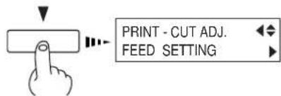
6 Use the [▼] key to choose [FEED SETTING].
7 Press the [▶] key to make the following screen appear on the display.
8 Enter the correction value read in step 5. Select the correction value with the [▲] [▼] key, and press the [ENTER] key.
9 Repeat steps 6 through 8 and enter the correction value of [SCAN SETTING].

Stopping Printing or Cutting Operations
Stopping Printing or Cutting
1 Press the [PAUSE] key.
2 Halt transmission of printing instructions from the computer.
3 Hold down the [SETUP] key for one second or longer. Any remaining data is cleared.
The PAUSE LED lights up

The SETUP LED flashes
Pausing Printing or Cutting Operations
Press the [PAUSE] key. The PAUSE LED lights up.
The PAUSE LED lights up

To resume printing
Press the [PAUSE] key again. The PAUSE LED goes out.
The PAUSE LED goes out


Notice
Even when not in use, keep the machine in an environment where the temperature is 5 to 40 °C (41 to 104 °F) and the humidity is 20 to 80 % (no condensation). In particular, be careful to make sure not to expose the machine to high temperatures of 40 °C (104 °F) or more.
When the machine is out of use for an extended period, then once a month, switch on the power and perform cleaning. When the machine's main power switch is left on, a warning beep sounds about once a month to remind you to perform cleaning. We recommend switching off only the sub power and leaving the main power on even when the machine is out of use for an extended period.
1 When the machine is out of use for about a month, a warning beep sounds and the following message appears on the display.
2 Press the [POWER] key to switch on the sub power.
Cleaning is performed automatically.
3 After cleaning has finished, hold down the [POWER] key for 1 second or longer to switch off the sub power.
PRESS THE POWER KEY TO CLEAN

The POWER LED lights up

The POWER LED goes out
4. Maintenance
This section describes how to clean the printing heads, daily care and maintenance, and the like.
Switching on the sub power automatically performs maintenance operations, including cleaning of the printing head. This means that there is normally no need to perform cleaning otherwise. If drop-out occurs with printed images, clean the printing head.
Cleaning the Printing Heads
1 Load media for printing-test use.
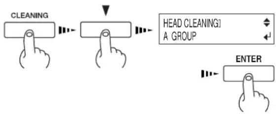
2 Press the [CLEANING] key, and press the [▼] key to select the printing-head group to clean. Press the [ENTER] key to start head cleaning. Also, holding down the [CLEANING] key for at least one second starts head cleaning for all heads.

Point
Printing-head Groups
A Group : Black, Cyan
B Group : Magenta, Yellow
C Group : Light cyan, Light magenta
3 After head cleaning has ended, holding down the [TEST PRINT] key for one second or longer starts a printing test.
4 Refer to "2-4 Printing -- Performing a Printing Test" and check the printing-test results. If a problem is found, repeat the cleaning.
flowchart
graph LR
    A["CLEANING"] --> B["HEAD CLEANING"]
    B --> C["A GROUP"]
    C --> D["ENTER"]
TEST PRINT

If Drop-out Persists Even After Carrying Out Cleaning Several Times

Point
Perform head cleaning only when there is dot drop-out (gaps) or printing becomes faint.
Performing head cleaning more than necessary subjects the heads to wear and consumes ink. In particular, cleaning performed at the [POWERFUL] menu for [HEAD CLEANING] can cause premature head wear and consume large amounts of ink. (Performing cleaning at the [POWERFUL] consumes approximately 60 cc of ink for each group.)
1 Load media for printing-test use.
2 Press the [MENU] key, and press the [▼] key to make the following screen appear on the display.
3 Press the [▶] key, and press the [ ] key to display the screen shown in the figure.
You can choose to perform cleaning of only the A group heads, B group heads, C group heads or only the left head by pressing the [▼] key more times.
Press the [ENTER] key to start head cleaning ("medium").

flowchart
graph LR
    A["MENU"] --> B["HEAD CLEANING"]
    style A fill:#f9f,stroke:#333
    style B fill:#bbf,stroke:#333
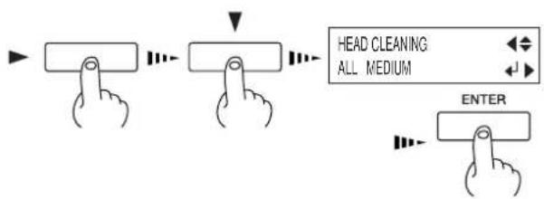
4 When head cleaning finishes, perform a printing test to check the results.

If Performing POWERFUL Cleaning Several Times Does Not Correct the Drop-out Problem
If performing cleaning several times at the [POWERFUL] menu does not correct the image drop-out problem, use the included cleaning kit. For information on how to use the cleaning kit, refer to the following section, "Cleaning Using the Cleaning Kit."
4-2 Cleaning Using the Cleaning Kit
Cleaning using the cleaning kit should be carried out when automatic cleaning and forced cleaning from the [HEAD CLEANING] menu fail to correct image drop-out. Remove any ink buildup of dust or grime around the printing heads, which can cause image drop-out or ink drips. We also recommend performing periodic cleaning using the cleaning kit to prevent problems like these during printing.
If image drop-out persists even after performing cleaning with the cleaning kit, or if the cleaning kit is used up, contact your authorized Roland DG Corp. dealer or Roland DG Corp. service center.
The heads are consumable parts. The useful life is six billion shots per nozzle.

Notice
Before starting cleaning, read through this section carefully to familiarize yourself with the procedures, then carry out the cleaning operations quickly and accurately.
Cleaning is performed while the caps on the printing heads are detached, so cleaning must be completed before the heads dry out. It is suggested that cleaning be completed in thirty minutes or less.
If it appears that cleaning operations may take more than thirty minutes, stop the cleaning operations and follow the steps below.
- Attach the cover and tighten the screws.
- Press the [ENTER] key. (Cleaning of the printing heads starts.)
- Again carry out cleaning using the cleaning kit.
Cleaning Using the Cleaning Kit
1 Switch on the main power switch on the back of the machine.
Leave media unloaded at this time.
2 While holding down the [CLEANING] key, switch on the [POWER] key.
3 Press the [▲ and [▼] keys to select [CLEANING].
4 Press the [ENTER] key.
The screen shown in the figure appears, and the printing carriage moves to the middle of the left cover.
5 Make sure the screen shown in the figure is displayed, then remove the four screws and open the left and right covers.

Notice
Take care not to drop the covers when removing them. If dropped, the impact may cause them to break.
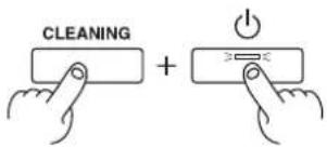
MAINTENANCE CLEANING


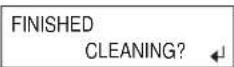

6 To discharge static electricity from your body, touch the location shown in the figure.
7 Clean the heads and the area around the heads on the left side of the machine. Use a cleaning stick to wipe off any grime from the stainless-steel frame for the heads and the plastic areas on either side of the heads.

Notice
Be sure to use one of the included cleaning sticks.
Do not touch the nozzle surface of the heads.
8 Clean the surface of the stainless-steel frame on the right side of the machine. Use a cleaning stick to wipe away any buildup of dust and ink from the surface of the stainless-steel frame. If there is dust on the sponges, wipe it off with the cleaning stick.

Point
Give special attention to removing the fibrous dust that tends to build up on the heads.
9 Clean the rubber caps and the area around them. Use a cleaning stick to wipe off any buildup of dust or grime from the rubber caps. If there is dust on the sponges, wipe it off with the cleaning stick.

Notice
If no grime is present, do not touch the sponges inside the rubber caps.
When removing grime adhering to the sponge inside a rubber cap, touch the sponge gently with the tip of the cleaning stick to pick up the grime. Rubbing forcefully may damage the surface of the sponge.

natural_image
Line drawing of a hand operating a printer with a paper airplane (no text or symbols)


Continued on the next page
10 Clean the wiper. Use a cleaning stick to wipe away any buildup of dust and grime from the wiper.

Point
Replacing the Wiper
If the message [REPLACE WIPER] appears on the display, replace the wiper with a new one. As a rule of thumb, the message prompting you to replace the wiper appears when cleaning has been performed 500 times (with [ALL] selected for head cleaning). For information on how to replace the wiper, see "4-3 Replacing the Wiper."
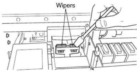
11 Attach the left and right covers and secure them closed by tightening the screws.

12 Press the [ENTER] key.
The screen shown in the figure appears, the printing heads return to the standby position, and head cleaning starts automatically. After cleaning has finished, switch off the sub power.

13 Again press the [POWER] key to switch on the sub power.
14 Load media, and carry out a printing test.
Examine the results of the printing test and make sure that all dots are printed attractively. If necessary perform head cleaning to make the dots clean and even.
4-3 Replacing the Wiper
If the message shown in the figure appears, replace the wiper with a new part.
TIME FOR WIPER REPLACE
1 Follow steps 1 through 3 in "4-2 Cleaning Using the Cleaning Kit" to display the screen shown in the figure, and press the [ENTER] key.
MAINTENANCE WIPER REPLACE
2 Follow steps 5 and 6 in "4-2 Cleaning Using the Cleaning Kit" to detach the right cover, and discharge static electricity from your body.
3 Using tweezers, grasp the bottom portion of the wiper and take it off the hook.
4 Remove the wiper.


Point
The wiper has a rubber surface and a felt surface. Attach it so that the rubber surface faces the front.

5 Install the new wiper. Use the tweezers to press the area shown in the figure and engage the wiper on the hook.

Notice
When installing the wiper, be sure to engage it on the hook. If the wiper is not hooked, it may fall off during use. Use the included tweezers to install and detach the wiper.

6 Follow steps 11 through 13 in "4-2 Cleaning Using the Cleaning Kit" to attach the right cover and carry out a printing test.
The machine and the inside of the front cover may become soiled with ink during printing. The cleaning methods described below let you continue printing without affecting the printed media or the machine.

Notice
- When carrying out any cleaning other than cleaning using cleaning sticks, switch off the main power. Before turning off the main power, press the [POWER] key to switch off the sub power.
- Never lubricate the mechanisms.
- Do not clean with solvents (such as benzine or thinners).
- Periodically clean the platen, grit rollers, and media clamps.
- Do not touch the printing heads or allow the printing heads to come in contact with anything except ink.
Cleaning the Body
Use a cloth moistened with water then wrung well, and wipe gently to clean. Wipe the operation panel and display gently with a clean, soft cloth.
Cleaning the Platen
Moisten a cloth with neutral detergent diluted with water, wring dry, and wipe gently.
For buildup of cutting dust on the platen, use a commercially available brush to brush them away toward the front. When doing this, do not use a metal brush.
Cleaning the Grit Rollers
Use a commercially available brush to remove dust and other detritus.
Any adhering grime may prevent the media from being held in place securely.
Cleaning the Pinch Rollers
Moisten a cloth with neutral detergent diluted with water, wring dry, and wipe gently.
Cleaning the Front Cover
Use a cloth moistened with water then wrung well, and wipe gently to clean.
Cleaning the Media Clamps
If there is buildup of ink or dust, moisten a cloth with neutral detergent diluted with water, wring dry, and gently wipe the surface.
4-5 Disposing of Discharged Ink
The bottle stand for the drain bottle is provided with a window to help determine when discharged ink needs to be disposed.
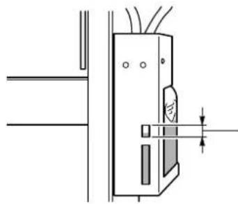
natural_image
Technical line drawing of a mechanical assembly with no visible text or symbolsWhen the discharged ink is within this range, dispose of it.
If discharged ink is allowed to exceed this range, it may spill when the bottle is removed.
Dispose of ink in the drain bottle as described below.

Notice
Discharged ink is flammable and contains toxic ingredients. Do not attempt to incinerate discharged ink or discard it with ordinary trash. Also, do not dispose of it in sewer systems, river, or streams. Doing so may have an adverse impact on the environment.
Procedure for Disposing of Discharged Ink
1 Press the [POWER] key at least one second to switch off the sub power.
The POWER LED goes out
2 Remove the drain bottle.

3 Dispose of discharged ink properly, in accordance with regional laws and regulations.

Point
If any ink gets on your hands or clothing, wash it off as soon as possible. Ink stains may become difficult to remove if allowed to stand.

Do not touch the tip of the blade with your fingers.
Doing so may result in injury, and the cutting performance of the blade will be impaired.
1 Press the [MENU] key, and press the [▼] key to make the following screen appear on the display.
2 Press the [ENTER] key to make the following screen appear on the display.
When the screen shown in the figure appears, the printing carriage simultaneously moves to the left.
3 Loosen the tool securing screw in the figure, remove the blade holder from the cutting carriage.
4 Remove the old blade.
5 Replace with a new blade.
6 Support the tool-securing screw from below and install the blade holder.
Insert the blade holder until the collar is flush with the carriage.
7 Tighten the tool securing screw.
Tug the blade holder upward to make sure it does not come loose.
8 Close the front cover, and press the [ENTER] key.
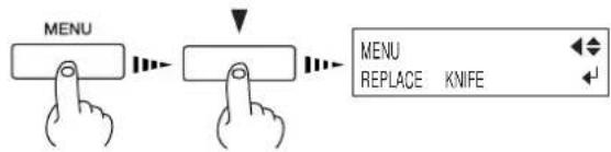
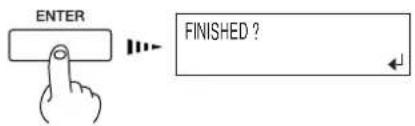


Press the push-pin

It snaps into place with an audible click.

natural_image
Illustration of hands using a tool to adjust or install a mechanical component, with an inset showing a close-up of the component (no text or symbols present)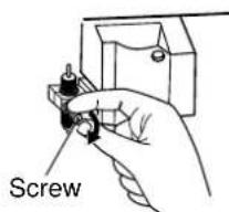
4-7 How to Replace the Separating Knife

Do not touch the tip of the separating knife with your fingers.
Doing so may result in injury.

Do not touch the control panel while head cleaning or other cleaning is in progress.
The printing carriage may move and cause injury.

Notice
Do not try to pull out the printing carriage by hand. The printing carriage is pulled out automatically through menu operation. If the machine is allowed to stand for a prolonged period with the printing carriage pulled out, head clogging or even damage to the printing heads may occur.
If the separating knife becomes dull, replace with the included replacement blade.
1 Press the [MENU] key, and press the [▼] key to make the following screen appear on the display.
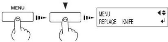
2 Press the [ENTER] key to make the following screen appear on the display.
When the screen shown in the figure appears, the printing carriage simultaneously moves to the left.

3 Open the front cover, and then remove the separating knife.

Point
If a blade remains in the printing carriage, use the tweezers in the cleaning kit to remove it.

(2) Grasp the screw portion, and slowly pull it out in the direction of the arrow.
(1) Loosen the screw until it slips out.
4 Replace with a new knife.

5 Install the separating knife.

natural_image
Mechanical device diagram showing a lever mechanism with rotating components and motion arrows (no text or symbols)(1) Grasp the screw portion and slowly insert it into the groove.
(2) Tighten the screw.
6 Close the front cover and press [ENTER] key.

Notice
Before attempting to move the machine, clean the heads. Four optionally available cleaning cartridges are required to clean all the heads. Each cleaning cartridge can be used to perform cleaning three times.
Do not tilt the machine at a large angle. Ink or discharged fluid remaining in the machine may leak or spill, causing breakdown or malfunction.
Be sure to use SOL INK cleaning cartridges. Use of any other type may result in breakdown.
1 If there is media loaded, hold down the [SETUP] key for 1 second or longer to cancel setup, then remove the media (see "2-3 Loading Media --Removing the Media").
2 Press the [MENU] key, and press the [▼] key to make the following screen appear on the display.
3 Press the [▶]key to make the following screen appear on the display.
4 Use the [▼] key to select [HEAD WASH], then press the [ENTER] key.
5 When the display shown in the figure appears, discard the discharged ink in the drain bottle.

Notice
Be sure to discard the discharged ink. Attempting to clean the heads while discharged ink remains may cause discharged ink to overflow from the bottle. For more information about how to dispose of discharged ink, see "4-5 Disposing of Discharged Ink."
6 Mount the drain bottle and press the [ENTER] key to display the screen shown in the figure.


flowchart
graph LR
    A["Hand icon"] --> B["INK CONTROL"]
    B --> C["HEAD WASH"]
    C --> D["ENTER"]

REMOVE SOL CRT. 1 2 3 4 5 6 7 8 9 10 11 12
Insert a cleaning cartridge into the ink cartridge port for the flashing number.
SET SOL CL-LIQUIDC 1 2 3 4 5 6 7 8 9 10 11 12
7 After you have pulled out all the ink cartridges whose colors are flashing, head cleaning starts. Follow the messages on the display to carry out the procedure.
When cleaning for the first two colors finishes, the display returns to the screen shown in step 6. Follow the messages on the display to perform cleaning for the remaining four colors.
8 When head cleaning finishes, the sub power shuts of automatically.
Switch off the main power switch.
9 Detach the power cord and the cable connecting the unit to the computer.
10 Remove the drain bottle and stopper the drain tube.
11 Secure the printing carriage in place.
For information on how to secure in place, refer to "1-3 Assembling and Installing -- Step 4: Remove the Protective Media."

Switch to "O"

5. Menus and Keys
This section contains a flowchart of the menus and describes the control-panel keys and the menu items.
For details about each of the menus, see the "5-2 Description of Menus."

flowchart
graph TD
    A["Input Image"] --> B["Roland SC-540 Ver.1.00"]
    B --> C{When the power is turned on for the first time, or turned on after removing the ink}
    C --> D["Roland SC-540 SOL INK LcLm"]
    D --> E{No ink is filled.}
    E --> F["Select INK TYPE SOL INK LcLm"]
    F --> G["INSTALL DRAIN BOTTLE"]
    G --> H["SET SOL CL-LIQUID 123456789101112"]
    H --> I["SET SOL CRT 123456789101112"]
    I --> J["FILLING INK..."]
    J --> K["SET SOL INK cartridge"]
    K --> L["Insert SOL INK cartridge"]
    L --> M["The system will execute ink fill."]
    M --> N["SETUP SHEET ROLL EDGE PIECE"]
    N --> O{If["EDGE SENSE"] is["DISABLE"].}
    O --> P["SETUP SHEET ROLL"]
    P --> Q["Use ▲ or ▼ to select. Press the [ENTER"] key to enable the setting.]
    Q --> R["PRESS SETUP KEY"]
    R --> S["SETUP SHEET ROLL"]
    S --> T["Load the media and press"]
    T --> U["SETUP"]
    U --> V["NOW PROCESSING.."]
    V --> W["W1000mm L1230mm"]
    W --> X["Printing/cutting area of the loaded media (width). *This is not displayed when [ROLL"] or["EDGE"] has been selected.]
    X --> Y["Top menu"]
    Z["MENU + MENU LANGUAGE ENGLISH"] --> AA["Select the installed ink type and press the [ENTER"] key. Attach the drain bottle, and_press["ENTER"] key.] --> AB["SET SOL CL-LIQUID 123456789101112"]
    AB --> AC["SET SOL CRT 123456789101112"]
    AC --> AD["FILLING INK..."]
    AD --> AE["SET SOL INK cartridge. The system will execute ink fill."]
    AE --> AF["SETUP SHEET ROLL EDGE PIECE"]
    AF --> AG["Use ▲ or ▼ to select. Press the [ENTER"] key to enable the setting.]

flowchart
graph TD
    A["CUT CONFIG"] --> B["FORCE 50gf → 50gf"]
    B --> C["SPEED 40cm/s → 40cm/s"]
    C --> D["OFFSET 0.250mm → 0.250mm"]
    D --> E["UP - SPEED 60cm/s → 60cm/s"]
    style A fill:#f9f,stroke:#333
    style B fill:#ccf,stroke:#333
    style C fill:#cfc,stroke:#333
    style D fill:#fcc,stroke:#333
    style E fill:#cff,stroke:#333
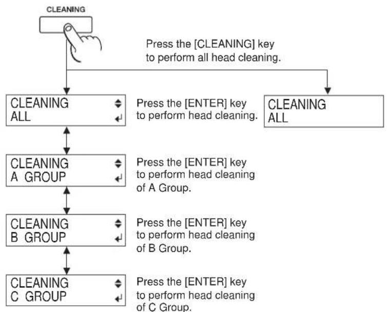
flowchart
graph TD
    A["CLEANING"] --> B["CLEANING ALL"]
    B --> C["CLEANING A GROUP"]
    C --> D["CLEANING B GROUP"]
    D --> E["CLEANING C GROUP"]
    E --> F["Press the [ENTER"] key to perform head cleaning.]
    F --> G["CLEANING ALL"]
    G --> H["Press the [ENTER"] key to perform all head cleaning.]
    H --> I["CLEANING ALL"]
    I --> J["Press the [ENTER"] key to perform head cleaning of A Group.]
    J --> K["CLEANING B GROUP"]
    K --> L["CLEANING C GROUP"]
    L --> M["Press the [ENTER"] key to perform head cleaning of B Group.]
    M --> N["CLEANING C GROUP"]

flowchart
graph TD
    A["CLEANING"] --> C["MAINTENANCE CLEANING"]
    B["+"] --> C
    C --> D["MAINTENANCE WIPER REPLACE"]

- Go back to the previous menu screen.

- Advance to the next menu screen (or move down one level).

- Select an item. - Select the value for a setting

- Executes the menu - Locks in the value for a setting
- Move to the previous menu screen or the next menu screen
- Select the value for a setting
- Moves the media (when specifying the printing location)

- Move to a submenu screen
- Moves the printing carriage (when specifying the printing location)

- Move to the previous menu screen
- Moves the printing carriage (when specifying the printing location)
ENTER

- Executes the menu
- Locks in the value for a setting

flowchart
graph TD
    A["MENU"] --> B["MENU EDGE DETECTION"]
    B --> C["MENU HEAD HEIGHT"]
    C --> D["MENU ADJUST BI-DIR"]
    D --> E["ADJUST BI-DIR TEST PRINT"]
    E --> F["ADJUST BI-DIR SETTING NO.1"]
    F --> G["ADJUST BI-DIR LOAD PRESETTING"]
    G --> H["ADJUST BI-DIR SAVE PRESETTING"]
    H --> I["MENU PRINT - CUT ADJ."]
    I --> J["PRINT - CUT ADJ. TEST PRINT"]
    J --> K["PRINT - CUT ADJ. FEED SETTING"]
    K --> L["PRINT - CUT ADJ. SCAN SETTING"]
    L --> M["PRINT - CUT ADJ. AUTO"]
    M --> N["To the [CALIBITATION"] menu]

    subgraph Edit/Enable/Disable/Enable/Disable
        B --> B1["EDGE DETECTION ENABLE ENABLE ENABLE / DISABLE"]
        C --> C1["HEAD HEIGHT HIGH LOW HIGH / MIDDLE / LOW"]
        D --> D1["ADJUST BI-DIR TEST PRINT"]
        E --> E1["PRESS ENTER KEY"]
        F --> F1["H1 H2 H3 0 0 0"]
        G --> G1["LOAD PRESETTING 1"]
        H --> H1["SAVE PRESETTING 1"]
        I --> I1["FEED SETTING +1.0mm +1.0mm -5.0 to +5.0 (In steps of 0.1)"]
        J --> J1["SCAN SETTING +1.0mm +1.0mm -5.0 to +5.0 (In steps of 0.1)"]
        K --> K1["END"]
        L --> L1["END"]
        M --> M1["END"]
        N --> N1["END"]
    end
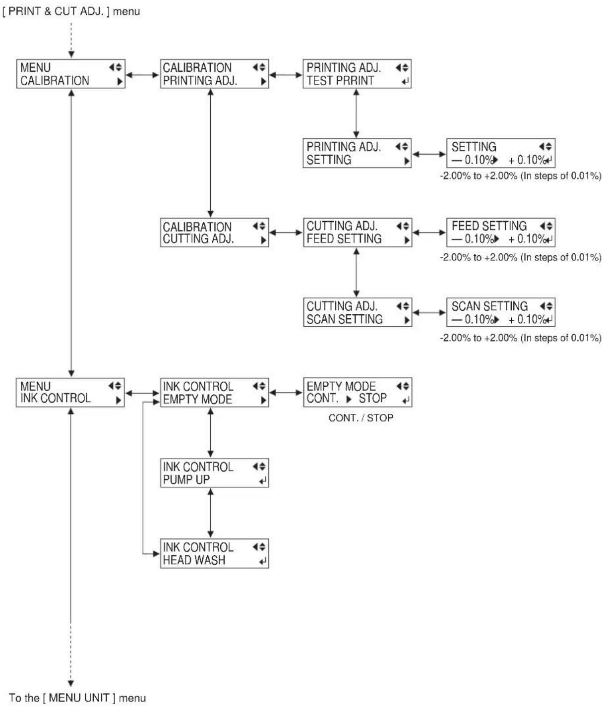
flowchart
graph TD
    A["[ PRINT & CUT ADJ. "] menu] --> B["MENU CALIBRATION"]
    B --> C["CALIBRATION PRINTING ADJ."]
    C --> D["PRINTING ADJ. TEST PRRINT"]
    D --> E["PRINTING ADJ. SETTING"]
    E --> F["SETTING 0.10% + 0.10%"]
    F --> G["-2.00% to +2.00% (In steps of 0.01%)"]
    C --> H["CALIBRATION CUTTING ADJ."]
    H --> I["CUTTING ADJ. FEED SETTING"]
    I --> J["FEED SETTING 0.10% + 0.10%"]
    J --> K["-2.00% to +2.00% (In steps of 0.01%)"]
    I --> L["CUTTING ADJ. SCAN SETTING"]
    L --> M["SCAN SETTING 0.10% + 0.10%"]
    M --> N["-2.00% to +2.00% (In steps of 0.01%)"]
    B --> O["MENU INK CONTROL"]
    O --> P["INK CONTROL EMPTY MODE"]
    P --> Q["EMPTY MODE CONT. STOP CONT./STOP"]
    P --> R["INK CONTROL PUMP UP"]
    R --> S["INK CONTROL HEAD WASH"]
    S --> T["To the [ MENU UNIT "] menu]

flowchart
graph TD
    A["[ INK CONTROL "] menu] --> B["MENU UNIT"]
    B --> C["UNIT mm ▶ INCH mm / INCH"]
    B --> D["MENU FACTORY DEFAULT"]
    D --> E["NOW PROCESSING.."]
    D --> F["MENU SYSTEM REPORT"]
    F --> G["PERFORMING TEST PRINT"]
    F --> H["MENU ENV. MATCH"]
    H --> I["NOW PROCESSING.."]
    H --> J["MENU PREFERED"]
    J --> K["PREFEED DISABLE ▶ ENABLE DISABLE / ENABLE"]
    J --> L["MENU CUTTING PRIOR"]
    L --> M["CUTTING PRIOR COMMAND ▶ MENU COMMAND / MENU"]
    L --> N["MENU REPLACE KNIFE"]
    N --> O["FINISHED?"]
    N --> P["MENU INK REMAINING"]
    P --> Q["1 ■■ 2 ■■ 3 ■■ 4 ■■ 5 ■■ 6 ■■ 7 ■■ 8 ■■"]
    P --> R["9 ■■ 10 ■■ 11 ■■ 12 ■■"]
    P --> S["To the [ HEAD CLEANING "] menu]

flowchart
graph TD
    A["INPUT REMAINING"] --> B["MENU HEAD CLEANING"]
    B --> C1["HEAD CLEANING ALL MEDIUM"]
    B --> C2["HEAD CLEANING ALL POWERFUL"]
    C1 --> D1["HEAD CLEANING A MEDIUM"]
    C1 --> D2["HEAD CLEANING A POWERFUL"]
    C2 --> D3["HEAD CLEANING B MEDIUM"]
    C2 --> D4["HEAD CLEANING B POWERFUL"]
    C3 --> D5["HEAD CLEANING C MEDIUM"]
    C3 --> D6["HEAD CLEANING C POWERFUL"]
    D1 --> E1["Press TEST PRINT"] key at least one second during screens appeared, test print start.
    D2 --> E2["Press TEST PRINT"] key at least one second during screens appeared, test print start.
    D3 --> E3["Press TEST PRINT"] key at least one second during screens appeared, test print start.
    D4 --> E4["Press TEST PRINT"] key at least one second during screens appeared, test print start.
    D5 --> E5["Press TEST PRINT"] key at least one second during screens appeared, test print start.
    D6 --> E6["Press TEST PRINT"] key at least one second during screens appeared, test print start.
To the [EDGE DETECTION] menu
| Top menu | Submenu | Function | Setting range | Default value |
| EDGE DETECTION | — | This specifies whether detection of the front and rear edges of the media is enabled or disabled.This should normally be set to [ENABLE].When loading transparent media, set this to [DISABLE]. When set to [DISABLE], then during media setup only the [ROLL] selection is available. When doing this, ensure a margin of 75 mm (3 in.) or more from the leading edge of the media to the start position for printing or cutting. | ENABLE/ DISABLE | ENABLE |
| HEAD HEIGHT | — | This sets the height of the printing heads.To make the setting, display this menu, then move the lever on the side of the unit's printing carriage. | HIGH/ MIDDLE/ LOW | MIDDLE |
| ADJUST BI-DIR | TEST PRINT SETTING NO.1 SETTING NO.2 SETTING NO.3 SETTING NO.4 LOAD PRESETTING SAVE PRESETTING | This adjusts for slippage when performing bidirectional printing.This must be readjusted when you have replaced the media with a different type or adjusted the head height.[TEST PRINT]: This menu is for verifying the adjustment.[SETTING NO.1], [SETTING NO.2], [SETTING NO.3], [SETTING NO.4]: This sets the correction value.[LOAD PRESETTING]: This loads adjustment values set in memory 1 through 8.[SAVE PRESETTING]: This takes the adjustment values set for No. 1 through No. 4 and saves them as [PRESETTING 1] through [PRE- SETTING 8]. You can save up to eight adjustment-value patterns. | -30 to +10(In steps of 1/2) | 0 |
| PRINT - CUT ADJ. | TEST PRINT FEED SETTING SCAN SETTING AUTO | [TEST PRINT]: This prints a test pattern for adjustment use.[FEED SETTING]: This sets the adjustment value for the media-feed direction.[SCAN SETTING]: This sets the adjustment value for the left-right direction (the carriage-movement direction).[AUTO]: Alignment of the printing and cutting positions is performed automatically. | —[FEED SETTING][SCAN SETTING]-5.0 to +5.0 mm(In steps of 0.1 mm)— | —0 mm0 mm— |
| CALIBRATION | PRINTING ADJ. CUTTING ADJ. | This corrects for errors in the amount of feed of the grit rollers due the type of media.Be sure to make this setting when you have replaced the media with a different type.Make this setting again when horizontal stripes are plainly visible on printing results.[TEST PRINT]: This menu is for verifying the adjustment.[SETTING]: This sets the correction value.This corrects for the cutting length (distance correction) when using the machine for cutting only. When using the machine for printing and cutting, always set the offset value to [0].[FEED SETTING]: This sets the adjustment value for the media-feed direction.[SCAN SETTING]: This sets the adjustment value for the scan direction (the carriage-movement direction). | [PRINTING ADJ.-2.0% to +2.0%(In steps of 0.05%)[CUTTING ADJ.-2.0% to +2.0%(In steps of 0.01%) | 0%0% |
| INK CONTROL | EMPTY MODE | [EMPTY MODE]: When replacement of the ink cartridge becomes necessary while printing is in progress, this setting determines whether printing continues or pauses. This setting is used when the ink cartridge cannot be changed immediately during printing, such as during unattended operation at night.[CONT.] causes printing to continue without pause even if ink refilling becomes necessary. To replace an ink cartridge, press the [PAUSE] key to pause operation, then replace with a new cartridge. Pressing the [PAUSE] key again resumes printing.Printing continues with the small amount of ink remaining, so the printed image may become faint as the ink runs out. In general, it should possible to perform about 1 m^2( 10ft^2) of printing once this message appears, although the actual varies widely according to the amount of ink needed for the particular image. Printing is continued only for the data currently being printed. Operation stops after one image is output.[STOP] causes operation to pause immediately when the ink cartridge needs to be changed. Printing is resumed by replacing the cartridge. Please note, however, that the colors of an image in progress may no longer be perfectly matched if the unit is allowed to remain paused for two or three hours before resuming printing.[PUMP UP] : Drains ink from the printing heads.[HEAD WASH] : This washes the printing heads with optionally available cleaning cartridges. | [EMPTY MODE] CONT./ STOP | [EMPTY MODE] STOP |
| PUMP UP HEAD WASH | ||||
| UNIT | — | This selects millimeters or inches as the unit of measurement for the width displayed on the top menu after setting up the media. When inch display is used, values are displayed to the first digit to the right of the decimal point. | mm / INCH | mm |
| FACTORY DEFAULT | — | This returns all menu settings to their original values when shipped from the factory.For more about the factory defaults for the various settings, see the "Default value" entry for each menu setting in this section. | — | — |
| SYSTEM REPORT | — | This prints the current status of settings and other system information. | — | — |
| ENV.MATCH | — | This performs automatic adjustment on the machine to obtain a state optimized to the operating environment (temperature and humidity). | — | — |
| PREFEED | — | This specifies whether the media prefeed function is enabled or disabled.When set to [ENABLE], an amount of media equal to the size of the data sent from the computer is fed out first, and then printing or cutting are performed.When using the [PREFEED] function, set [EDGE SENSE] to [ENABLE]. | DISABLE/ ENABLE | DISABLE |
| CUTTING PRIOR | — | This setting is made cutting conditions set with a program are made to take priority. When set to [MENU], cutting is performed using the values set with the machine. | COMMAND/ MENU | COMMAND |
| REPLACE KNIFE | — | This setting is used when replacing the separating knife, or installing or removing cutter blade | — | — |
| INK REMAINING | — | This shows the amount of ink left after each of the ink cartridges has been installed.The fewer the markers ("■"), the less ink is left.* If a partially used ink cartridge is removed and reinstalled, or if a partially used ink cartridge is installed, the cartridge is taken to be unused, and the displayed amount of remaining ink is not true. | — | — |
| HEAD CLEANING | ALL MEDIUMA MEDIUMB MEDIUMC MEDIUMALL POWERFULA POWERFULB POWERFULC POWERFUL | If print shows a problem, clean the printing head.Because cleaning subjects the head to wear and consumes ink, it should only be performed when absolutely necessary. Performing cleaning from the Powerful menu in particular subjects the head to early wear and used up large amounts of ink.[ALL MEDIUM]/[A MEDIUM]/[B MEDIUM]/[C MEDIUM]:Performs cleaning of the printing heads. After cleaning, carry out a printing test to make sure there are no problems with printing quality. Normally, head cleaning should be performed by pressing the [CLEANING] key.[ALL POWERFUL]/[A POWERFUL]/[B POWERFUL]/[C POWERFUL]: Used when performing cleaning with Medium several times does not restore the printing quality. After cleaning, carry out a printing test to make sure there are no problems with printing quality. | — | — |
| Key | Top menu | Function | Setting range | Default value |
 | — | This switches on and off the sub power. When the power is switched on, the POWER LED lights up. | — | — |
SETUP | — | This detects the presence and the width of the media, and displays the printable width.The SETUP LED flashes while detection of media width is in progress. When setup finishes, the SETUP LED lights up continuously.Also press this key when removing the media.Pressing this key when any of the various menu screens is displayed returns you to the top screen. (When this is done, media setup cannot be canceled.) | — | — |
PAUSE | — | The [PAUSE] key pauses printing. The PAUSE LED lights up while paused.Pressing this key again cancels the paused state.Holding down the [SETUP] key for about 1 second while paused causes remaining data to be cleared and cancels the media's setup state. | — | — |
SHEET CUT | — | This cuts off the media at the present location of the blade tip. Press this to cut off the portion already printed or cut from the roll.You cannot sever a piece of media while printing or cutting is in progress. | — | |
CUT CONTROL | FORCE | This enters the menu for setting the conditions for cutting. You can set the values for blade force, cutting speed, blade offset compensation, and tool movement speed when raising the tool.For more information, see "Display Menus Flowchart." * When [CUTTING PRIOR] on the machine's display menu has been set to [COMMAND], the program's settings for the cutting conditions take priority.To give priority to the cutting conditions set on the machine, turn off the program settings, or set the [CUTTING PRIOR] menu to [MENU]. | [FORCE]30 to 300 gf(In steps of 5 gf)[SPEED]1 to 60 cm/s(In steps of 1 cm/s)[OFFSET]0 to 1.5 mm(In steps of 0.025 mm)[UP-SPEED]1 to 60 cm/s(In steps of 1 cm/s) | [FORCE]50 gf[SPEED]40 cm/s[OFFSET]0.25 mm[UP-SPEED]60 cm/s |
AUTO ALIGN | BASE -ALIGN | Pressing the [AUTO ALIGN] key after setup has finished displays the screen for selecting the mode for reading crop marks.[BASE-ALIGN]: This reads the four crop marks and corrects the axes and distance for the origin-point location, scanning direction, and feed direction.[BASE]: This reads the lower-right crop mark and corrects only the origin-point location. | BASE -ALIGN/BASE | — |
 | — | This sets the print or cutting start location in the scanning direction (the direction of carriage movement). Pressing the [BASE POINT] key when align points have already been set clears all align-point settings. | — | — |
ALIGN POINT | — | This corrects cutting data to align it with printing data that has been output. It is valid only during cutting. | — | — |
ENTER | — | This is used to accept, execute, or save the item shown on the display. | — | — |
 | — | Holding down the [TEST PRINT] key for one second or longer while the SETUP LED is lit performs a printing test. | — | — |
CLEANING | — | This enters the [HEAD CLEANING] menu for cleaning the printing heads.Cleaning can be performed while in any state.[ALL], [A GROUP], [B GROUP], or [C GROUP]: Begins cleaning of the printing heads. Holding down for one second carries out cleaning for all the heads.After cleaning, carry out a printing test to make sure there are no problems. | — | — |
  | — | Holding down this key for 1 second or longer performs a cutting test.If there are problems with the quality of cutting results for the media, press the [CUT CONFIG] key and adjust the cutting conditions. | — | — |
| — | This forces the blade to move up or down. | — | — | |
MENU | — | This enters the menu mode.When a menu is displayed, the [▲] and [▼keys move to the next menu, the [▶moves to a submenu, and the [ ]◀key moves to the previous screen. | — | — |
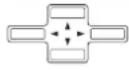 | — | These move the media and the cartridge.When a menu is displayed, these move among the menu items. | — | — |
 | LANGUAGE | This sets the language for screen messages. You can select either English or Japanese. | ENGLISH/JAPANESE | ENGLISH |
6. What to Do If...
This section describes error messages that may appear on the display and how to resolve problems that can occur during operation.
The machine doesn't run
The power does not switch on.
Is the main power switched on?
If the power does not come on when you press the [POWER] key, the main power at the back of the machine may not be switched on. Make sure the main power is switched on, then press the [POWER] key again.
Printing doesn't start when data is sent.
Are the network settings correct?
Make sure there are no errors in the network settings. For more information about making the connection to a network, see "Roland PrintServer Network Settings Guide."
Has media been loaded (the SETUP LED is lit)?
If the SETUP LED is not illuminated, make sure the media is loaded correctly and press the [SETUP] key to illuminate the SETUP LED.
Is the top menu displayed?
If the top menu isn't displayed, printing doesn't start even when data is sent from the computer. Press the [SETUP] key, and display the top menu.
Top menu
W 1234 mm L ---- mm
Is the PAUSE LED illuminated?
If the [PAUSE] key has been pressed and the PAUSE LED is lighted, the unit has been paused.
To resume printing or cutting, press the [PAUSE] key again. The PAUSE LED is extinguished, and printing or cutting resumes.
To terminate printing or cutting, first stop the transmission of printing or cutting instructions from the computer to this machine. Then press the [SETUP] key. Hold down for about 1 second. This deletes the printing or cutting instructions that have already been sent from the computer to this machine, and printing or cutting is stopped.
Has ink run out?
When printing or cutting data is sent while the screen shown in the figure is displayed, a message appears and a warning beep sounds.
At the same time, operation pauses. When the ink cartridge is replaced with a new one, printing or cutting starts.

This screen show 1 and 7 is run out.
Clean, attractive printing is impossible
If drop-out occurs with printed images.
Clean the printing heads (see "4-1 Cleaning the Printing Heads").
The printed images are not clean.
Clean the platen and pinch rollers. (see "4-4 Other Cleaning Tasks")
The printing heads scrape the surface of the media.
Is the loaded media very thick?
If media feed is not smooth because the media catches on the head, then adjust the height of the printing heads (see "2-3 Loading Media -- When Loading Thick Media (Only When printing)").
When the height of the printing head has been adjusted, it is necessary to perform bidirectional correction. For more information about bidirectional correction, see "3-5 Making Corrections for Printing -- Bidirectional Correction".
If you are using media that becomes uneven when printed, then perform unidirectional printing. With unidirectional printing, unevenness is less conspicuous than bidirectional printing.
Also, if the printing heads scrape the media even when the heads are raised, then do not use that media.
Doing so may not only cause paper jams, but may soil the media (the printing surface) and impair printing accuracy.
The results of printing are coarse.
Has feed correction been performed?
Correcting the amount of feed improves the dot-positioning accuracy in the feed direction, which can help enhance image quality.
If the type of media was changed, refer to "3-5 Making Corrections for Printing -- Feed Correction" and perform correction for feed.
Has bidirectional correction been performed?
If misalignment like in the example occurs when performing bidirectional printing, then carry out correction at the [BIDIRECTION] menu (see "3-5 Making Corrections for Printing -- Bidirectional Correction").
Be sure to make this setting when you have replaced the media with a different type, or if you have adjusted the head height and printing is misaligned.

OK: Correct

Not OK: Single lines not produced
The printing length is not accurate
Is the loaded media very thick?
To correct the amount of feed, refer to "3-5 Making Corrections for Printing -- Feed Correction" and make the correction to match the media you're using.
During printing, ink drips from the printing carriage and soils the media (the printing surface)
The following may cause ink to drip on the media during printing.
- Dust or fiber-containing grime around the heads may have absorbed ink.
- The heads scraping the media may have caused ink to fail to be discharged, resulting in ink buildup in the heads.
If this happens, refer to "4-2 Cleaning Using the Cleaning Kit" and clean the heads.
We recommend carrying out periodic head cleaning.
Also, before you start printing, perform a printing test to make sure there is no dot drop-out.
- Printing goes beyond the loaded media
Has the media been loaded at an angle?
If the loaded media is not straight, it may extend outside the printing or cutting area.
Refer to "2-3 Loading Media" and load the media correctly.
Media feed is not smooth (slippage occurs)
Is thick media being used?
If the surface of the media rubs against the printing heads and smooth feed is impossible, then adjust the height of the printing heads (see "2-3 Loading Media -- When Loading Thick Media (Only When Printing)").
When the height of the printing head has been adjusted, it is necessary to perform bidirectional correction (only when performing bidirectional printing). For more information about bidirectional correction, see "3-5 Making Corrections for Printing -- Bidirectional Correction."
If using sheet media, does the loaded media contact areas such as the stand's media flange?
If the sheet media contacts the media flange or the like at the back of the unit, shift the retainer to a location where the media doesn't make contact.
If the media touches an obstruction while printing is in progress, normal media feed is not performed, and image quality may suffer or the media may jam.
Is the sheet media loaded at an angle? Are the left and right edges of the media not straight?
If the media is loaded at an angle or if the left and right sides of the media are not cut straight, the location of the edges may shift as feed is carried out. This may cause the media to rub against the inner side of this machine or be displaced from the printing or cutting area.
Is the roll media loaded correctly?
If the roll media is not loaded correctly, the media may come loose or advance at an angle. Refer to "2-3 Loading Media -- Loading Roll Media" and load the media correctly.
The printing and cutting positions are not aligned
Is the media loaded correctly?
If the media is not loaded correctly, the media meanders as it is fed, and the printing and cutting positions become misaligned. Refer to the section "2-3 Loading Media" and load the media correctly.
The positions are not aligned even when [AUTO] in [PRINT-CUT ADJ.] is executed.
Depending on the type of media, automatic detection of square marks may not be possible.
In such cases, perform the alignment manually. (Refer to "3-6 Making Corrections for Printing and Cutting -- Adjusting Manually")
The printing and cutting positions in direction of carriage movement are misaligned.
The printing length in the carriage direction may change depending on the operating environment (temperature and humidity). Execute [ENV. MATCH] to adjust the machine to match the operating environment. (Refer to "1-5 Switching On the Power for the First Time -- Step 3 : Match the Machine to the Environment Where Installed")
Is the offset value for [CUTTING ADJ.] something other than zero (0)?
When you're performing printing and cutting, use a value of "0" in the menu of [CALIBLATION] - [CUTTING ADJ.].
Are you using media that exhibits large expansion and contraction?
When you're performing printing and cutting, misalignment occurs if the media expands or contracts. If this happens, try performing printing with crop marks, then setting the base point and one or more align points and performing cutting. This corrects for expansion and contraction of the media.
Automatic setting of the base point and the align point was performed, but the positions are not aligned.
Depending on the type of media or lamination, automatic detection of crop marks may not be possible. In such cases, set the base point and align point manually. (Refer to "2-7 Reloading the Media and Performing Cutting -- Aligning Manually")
The media becomes jammed
If [MOTOR ERROR : TURN OFF POWER] appears and operation stops
Follow the steps below to clear the error.
1 Press the [POWER] key to switch off the sub power.
2 Remove the jammed media. Cut off any creased or torn portions.
3 Press the [POWER] key to turn on the sub power.
4 Correct whatever caused the media to jam.
(For example, if thick media has been loaded, then adjust the height of the printing heads.)
5 Load the media and carry out setup.
6 Press the [CLEANING] key to perform head cleaning and a printing test (see "4-1 Cleaning the Printing Heads").
7 Send the printing or cutting data and perform printing or cutting.
![ROLAND SC-540 - If [MOTOR ERROR : TURN OFF POWER] appears and operation stops - 1](/content/2026/06/1254103/images/0e784f6b020153efbb1b18ad6f4ba7a6cd5d699f37d2895abd7487f19885e82e.jpg)
Point
Jammed media may damage or soil the printing heads. Be sure to perform head cleaning first before sending the printing data.
What to Do If the Printing Carriage Does Not Operate
During operation, if for some reason the printing carriage does not return to the standby position, then following the procedure, cap the printing heads, and contact the your authorized Roland DG Corp. dealer or service center.
If the printing carriage is allowed to stand for a prolonged period with the printing heads uncapped (that is with the printing carriage over the platen), the heads may become clogged or even damaged.
Capping the Printing Heads
1 Make sure the main power is switched off, then open the cover on the right side of the machine.
2 Open the front cover and move the printing carriage to the standby position by hand.
3 Insert the oval end of the pipe included with the machine into the hole in the bottom of the machine, then rotate the pipe.
The cap unit rises.
4 Align the guides at the two ends of the cap unit with the guides at the two ends of the printing carriage.
Turn the pipe more bring the cap unit close to the printing carriage.
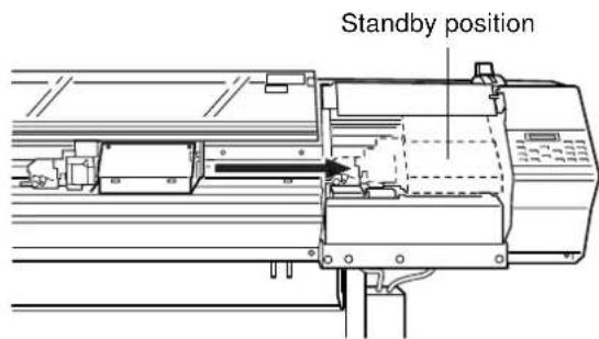


5 When the printing carriage comes into contact with the caps, rotate the pipe one or two turns more.

natural_image
Pure technical line drawing of a mechanical component or bracket (no text or symbols)Make sure the printing carriage and the caps are touching, then contact your authorized Roland DG Corp. dealer or service center.
| Messages | Meaning | Action |
| CLOSE THE COVER | An operation command was given while the cover or front cover is open. | Close the cover or front cover. |
| AVOIDING DRY-UP TURN OFF POWER | The printing head was returned to its standby position to be capped, canceling current printing job.Because emergency stop was effected more than 10 min. | Turn power off by pressing [POWER] key to reset.Interrupted printing is not resumed. Repeat printing from the beginning. |
| 1_2■3■4■5■6■7_8■9■10■11■12■ | Only a small amount of ink remains.* The message at left indicates that there is little remaining ink in the No. 1 and No. 7 ink-cartridge ports. | Replace the empty ink cartridge. |
| SET SOL CRT.1 2 3 4 5 6 7 8 9 10 11 12 | An ink cartridge was removed.A request to insert an ink cartridge was made from this machine. | Insert the specified ink cartridge. |
| REMOVE SOL CRT.1 2 3 4 5 6 7 8 9 10 11 12 | A request to remove an ink cartridge was made from this machine. | Take out the specified ink cartridge. |
| SET SOL CL-LIQUID1 2 3 4 5 6 7 8 9 10 11 12 | A request to insert a cleaning cartridge was made from this machine. | Insert the specified cleaning cartridge. |
| REMOVE SOL CL-LIQUID1 2 3 4 5 6 7 8 9 10 11 12 | A request to remove a cleaning cartridge was made from this machine. | Take out the specified cleaning cartridge. |
| SHEET SET ERROR SET AGAIN | The [SETUP] key was pressed even though no media is loaded.Setup was performed with no media at the correct location.An attempt was made to load media that is too small.[EDGE SENSE] is set to [ENABLE], but transparent media was loaded. | Load media at the correct location and press the [SETUP] key again (see "2-3 Loading Media"). Replace with media of loadable size.Wipe off the grime on the reflective tape, then perform setup again.Replace with media of loadable size.When using transparent media, set [EDGE SENSE] to [DISABLE] (see "5-2 Description of Menus"). |
| SHEET NOT LOADED PRESS SETUP KEY | Test printing was attempted with no media loaded. | Load the media and try again.Press the [ENTER] key to continue. |
| PINCHROLL ERROR LOWER PINCHROLL | The [SETUP] key was pressed with the pinch rollers up.The pinch rollers were raised during setup. | Move the sheet loading lever all the way to "LOAD" to lower the pinch rollers, then press the [SETUP] key (see "2-3 Loading Media"). |
| DATA ERROR CANCELING... | A problem was found in the data received. | Make sure the cable is attached securely. |
| SET HEAD HEIGHT TO *** | The head height and the loaded media do not match. | Change the head height to the specified height and press the [ENTER] key. |
* [1 2 3 4 5 6 7 8 9 10 11 12] indicate the numbers of the ink-cartridge ports. The character indicating the number of the ink-cartridge port flashes when action is necessary.
[Example]
SET SOL CRT. 123456789101112
If "4,5,10,11" is flashing: Install ink cartridges in ink-cartridge ports 4, 5, 10, and 11.
| Messages | Meaning | Action |
| EMPTY DRAIN BOTTLE | Discard discharged ink.* This message appears before operations that will discharge large amounts of ink.There is a chance of discharged ink overflowing if operations are carried out while the drain bottle is full. | Remove the drain bottle from this machine, discard the collected ink, then reinstall the drain bottle. Press the [ENTER] key to continue. |
| INSTALL DRAIN BOTTLE | Check that the drain bottle is set in position. | Set the drain bottle in place. Press the [ENTER] key to continue. |
| DO NOT USE MEDIA CLAMPS | Do not use media clamps.*This message appears when position the printing head at 1 (low). | Detach media clamps to the media.Press the [ENTER] key to continue. |
| SHEET TOO SMALL CONTINUE? | The size of the data is larger than the printing or cutting area of the loaded media. | To continue performing output without correcting this, press the [ENTER] key. At this time, the portion extending beyond the printing or cutting area is not output.To stop output, stop sending data from the computer, then press the [SETUP] key. Make the printing or cutting area wider such as by replacing the media with large media or changing the positions of the pinch rollers, then send the data again. |
| CAN'T PRINT CROP CONTINUE? | • The size of the data including the crop marks is larger than the printing or cutting area of the loaded media.• The size of the data being output is too small. | • To continue performing output without correcting this, press the [ENTER] key. At this time, the portion extending beyond the printing or cutting area and cropmarks are not output.To stop output, stop sending data from the computer, then press the [SETUP] key. Make the printing or cutting area wider such as by replacing the media with large media or changing the positions of the pinch rollers, then send the data again.• Make the size of the data at least 40 mm (scanning direction) by 15 mm (feed direction) (1-5/8 in. by 5/8 in.).To continue performing output without correcting this, press the [ENTER] key. At this time, the data output without printing the crop marks.To stop output, stop sending data from the computer, then press the [SETUP] key. Changethe size of the data, then send the data again. |
| MOTOR ERROR TURN OFF POWER | A motor error occurred. | Recovery from this problem is impossible. Use the POWER key to switch the power off and back on again.After rectifying the cause of the error (a media jam or the like), switch on the power.Do not leave the unit with the printing carriage not in standby position. |
| TEMPERATURE IS TOO LOW | The air temperature where installed is lower than the ambient temperature at which the unit can operate (approx. 5°C (41°F) or more lower). | Recovery from this problem is impossible. Use the [POWER] key to switch the power off. First raise the temperature of the area where installed, then switch on the power. |
| TEMPERATUREIS TOO HIGH | The air temperature where installed is higher than the ambient temperature at which the unit can operate (approx. 40°C (104°F) or more higher). | Recovery from this problem is impossible. Use the [POWER] key to switch the power off. First drop the temperature of the area where installed, then switch on the power. |
| CANCELED FORPROTECTING MOTOR | Continuous operation caused the pump motor to become hot, so operation was paused to prevent damage to the motor. | Press any key to cancel the message.Allow the unit to stand for about 40 minutes, then resume operation. |
| SERVICE CALLNo: * * * * | A problem occurred that resulted in a error that cannot be canceled.Correct operation became impossible because an error occurred.The useful life has ended for a component that must be replaced by a service technician. | Check the number shown on the display, then press the [POWER] key to switch off the power.After you switch off the power, inform your authorized Roland DG Corp. dealer or service center of the number that appeared on the display. |
| CARRIAGES AREDISCONNECTED | The cutting carriage or printing carriage are disconnected during printing, and printing cannot continue. | Recovery from this problem is impossible. Use the [POWER] key to switch the power off. |
| CROPMARK ERRORNOT FOUND | Automatic detection of crop marks by the [AUTO ALIGN] key could not be accomplished. | Load the media at the correct position and perform detection of crop marks again.Depending on the media, it may not be possible to detect crop marks automatically. If repeating automatic crop-mark detection results in an error again, then perform manual crop-mark detection (see "2-7 Reloading the Media and Performing Cutting"). |
| PINCHROLL ERRORINVALID LEFT POS.(or RIGHT) | The [SETUP] key was pressed while the left or right hand pinch roller was at a location where there is no grit roller. | Position the left or right hand pinch roller correctly (above a grit roller), then press the [SETUP] key. |
7. Appendix
Main Unit Specification
| SC-540 | ||
| Printing / Cutting method | Piezo ink-jet method / media-moving method | |
| Printing / Cutting width | 185 to 1346 mm (7-5/16 to 53 in.) | |
| Acceptable media widths | 210 to 1371 mm (8-5/16 to 54 in.) | |
| Conditions for usable media | -Cuttable media thickness: 0.08 to 0.22 mm (0.00315 to 0.00866 in.) (depending on media composition)-Maximum cuttable media thickness including base paper (backing paper): 0.4 mm (0.0157 in.)-Maximum printable media thickness including base paper (backing paper): 1.0 mm (0.039 in.)-Maximum diameter for roll media: 180 mm (7-1/16 in.)-Core inner diameter for roll media: 50.8 mm (2 in.) or 76.2 mm (3 in.)-Maximum weight for roll media: 20 kg (44.1 lb.) | |
| Ink cartridges Type | Exclusive SOL INK cartridge | |
| Capacity | 220 cc ±5 cc | |
| Color | The six colors black, cyan, magenta, yellow, light cyan, and light magenta | |
| Printing resolution (Printing dot resolution) | Max. 1440 dpi | |
| Distance accuracy (When printing) | Error of less than ±0.3% of distance traveled, or 0.3 mm, whichever is greater (at Roland PET-film, print travel: 1 m (39-3/8 in.)) | |
| Acceptable tool | Cutter (blade and blade holder) : Special blade for CAMM-1 series | |
| Cutting Speed | 10 to 600 mm/s (10 to 300 mm/s in the media-feed direction) | |
| Blade force | 30 to 300 gf | |
| Blade offset compensation | 0.000 to 1.500 mm (0 to 0.0591 in.) | |
| Software resolution (When cutting) | 0.025 mm/step (0.00984 in./step) | |
| Distance accuracy (When cutting) | Error of less than ±0.4% of distance traveled, or 0.3 mm, whichever is greaterWhen distance correction has been performed(when the setting for [CALIBRATION] - [CUTTING ADJ.] has been made):Error of less than ±0.2% of distance traveled, or 0.1 mm, whichever is greater | |
| Repetition accuracy (When cutting) | 0.1 mm or less (excluding stretching/contraction of the media)[Range for assured repetition accuracy] (*1)For media with a width exceeding 610 mm (24 in.): Length 4,000 mm (157-7/16 in.)For media with a width of 610 mm (24 in.) or less : Length 8,000 mm (315-15/16 in.) | |
| Repetition between printing and cutting | ±0.5 mm (±0.0197 in.) max. at 25°C (77°F)(excluding possible shift caused by expansion/contraction of the media and/or by reloading themedia, and provided that media length is under 3000 mm (118-1/16 in.) | |
| Alignment accuracy for printing and cuttingwhen reloading media | Error of less than ±0.5% of distance traveled, or 3 mm, whichever is greater[Guaranteed area of alignment for printing and cutting when reloading the media] (*2) | |
| Printing heads cleaning | Automatic cleaning and manual cleaning | |
| Interface | Bidirectional parallel interface (compliant with IEEE 1284: Nibble mode, ECP mode (noncompression)) and Ethernet 10Base-T or 100Base-TX | |
| Power-saving function | Auto-sleep | |
| Power consumption Printing | mode | Maximum: 2.0A/100V to 240V ±10% 50/60 Hz |
| Standby mode | Maximum: 0.6A/100V to 240V ±10% 50/60 Hz | |
| Acoustic noise level Printing | mode | 65dB (A) or less(According to ISO7779) |
| Standby mode | 40dB (A) or less | |
| Dimensions Main unit | 2699 mm [W] x 742 mm [D] x 519 mm [H] (106-5/16 in. [W] x 29-1/4 in. [D] x 20-7/16 in. [H]) | |
| With stand | 2699 mm [W] x 742 mm [D] x 1300 mm [H] (106-5/16 in. [W] x 29-1/4 in. [D] x 51-3/16 in. [H]) | |
| Packed dimensions | 2835 mm [W] x 850 mm [D] x 965 mm [H] (111-5/8 in. [W] x 33-1/2 in. [D] x 38 in. [H]) | |
| Weight Main unit | 136 kg (299.8 lb.) | |
| With stand | 152 kg (335 lb.) | |
| Packed weight | 221 kg (487.2 lb.) | |
| Environment Power on | Temperature: 15 to 32°C (59 to 89.6°F), Humidity: 35 to 80% (non-condensing) (*3) | |
| Power off | Temperature: 5 to 40°C (41 to 104°F), Humidity: 20 to 80% (non-condensing) | |
| Included items | power cord : 1, arm (Right) : 1, arm (Left) : 1, stand leg : 1, casters : 2, shafts : 2, bolts (Large) : 22, bolts (Small) : 8, washers : 6, hexagonal wrench : 1, pipe : 1, media flanges : 2, stoppers : 2, blade : 1, blade holder : 1, transport bars : 2, drain bottle : 1, bottle stand : 1, Software RIP : 1, user's manual : 1, replacement blade for separating knife : 1, Roland-PrintServer CD-ROM : 1, Roland PrintServer Network Settings Guide : 1, SOL INK Cleaning cartridges : 4, cleaning kit : 1 (cleaning sticks : 10, tweezers : 1, wipers : 2) | |
(*1) The following conditions must be satisfied:
- Media type: 3M Scotchcal Mastercut Film
- Roll media must be loaded on the shaft
- Side margins: 25 mm (1 in.) or more for both the left and right margins
- Front margin: 35 mm (1-1/8 in.) or more
- The required length for cutting must be pulled out from the roll
(*2)
- Temperature : 25 °C (77°F)
- Media type : SV-G-1270G
- Data size : 3,000 mm in the media-feed direction
1,000 mm in the carriage-movement direction
- The required length for cutting must be pulled out from the roll
- No lamination
- When reloading media, at the menu, select [BASE-ALIGN] to automatically detect crop marks.
- Excludes the effects of slanted movement and of expansion and contraction of the media.
(*3)Environment

bar
| Temperature (°C) | Humidity (%) | | ---------------- | ------------ | | 15 | 69 | | 27 | 80 | | 32 | 80 |Interface Specifications
| Standard | Bidirectional parallel interface (compliant with IEEE 1284: ECP mode (non compression)) |
| Input signals | STROBE (1BIT), DATA (8BITS), SLCT IN, AUTO FEED, INIT |
| Output signals | BUSY (1BIT), ACK (1BIT), FAULT, SLCT, PERROR |
| Level of input output signals | TTL level |
| Transmission method | Asynchronous |
Network Interface Specifications
10Base-T/100 Base-TX Ethernet network cable specifications
| Data | Values |
| Max. cable lenght | 100 m |
| Cable type | S/UTP Type "category 5" |
| Impedance | 100 Ohm |
| Connector type | RJ-45 |
Usable Media
Use genuine media for this machine.
A) Cuttable media thickness : 0.08 to 0.22 mm (0.00315 in. to 0.00866 in.) (depending on media composition)
B) Maximum media thickness, including base paper (peeled-off paper)
: Printing only 1.0 mm (0.039 in.)
: When performing cutting 0.4 mm (0.0157 in.)
C) Maximum diameter for roll media : 180 mm (7-1/16 in.) (surface to be printed or cut must face outward)
D) Core inner diameter for roll media: 50.8 or 76.2 mm (2 in. or 3 in.)
E) Maximum weight for roll media : 20 kg (44.1 lb.)
F) Roll media with a starting edge that is not taped down

Side view of roll media
Acceptable Media Width
210 to 1371 mm (8-5/16 to 54 in.)

other
| Media | Approx. 210 mm (8-5/16 in.) | Approx. 410 mm (16-1/8 in.) | Approx. 405 mm (15-15/16 in.) | Approx. 605 mm (23-13/16 in.) | Approx. 605 mm (23-13/16 in.) | Approx. 805 mm (31-11/16 in.) | Approx. 830 mm (32-11/16 in.) | Approx. 1030 mm (40-9/16 in.) | Approx. 1000 mm (39-3/8 in.) | Approx. 1200 mm (47-1/4 in.) | Approx. 1171 mm (46-1/8 in.) | Approx. 1371 mm (54 in.) | |-------|-------------------------------|-------------------------------|----------------------------------|----------------------------------|----------------------------------|----------------------------------|----------------------------------|----------------------------------|----------------------------------|----------------------------------|----------------------------------|--------------------------| | Total | - | - | - | - | - | - | - | - | - | - | - | - |

Point
Make sure the left and right pinch rollers are positioned above the grit rollers.
Use the middle pinch roller as required. Position one (or both) middle pinch rollers so as to form equally spaced intervals along the width of the media.
7-3 About the Printing or Cutting Area
The printing or cutting area along the horizontal plane (the direction in which the carriage moves) is determined by the position of the pinch rollers. The workable area spans the length between the two rollers, minus a margin of about 1.5 mm (about 0.06 in.) on both sides.
If "PIECE" has been selected and media length (the distance in the X direction as shown in the figure) is 2,000 mm (78-3/4 in.), the area is the same as when "EDGE" has been chosen.

* The arrows in the figure indicating the X and Y directions indicate respectively the positive directions of the X axis and Y axis.
When crop marks are printed, the printing or cutting area in the area shown above is reduced by an amount equal to the size of the crop marks (12.5 mm (0.5 in.) + 12.5 mm (0.5 in.)).

7-4 The Media-cutoff Location During Continuous Printing
The media-cutoff location that is used when a media-cutoff command is sent from the computer is determined as follows.

Cutting conditions and blade life vary according to the hardness of the media and the usage environment. Making the settings for the conditions described below does not automatically guarantee attractive cutting results in all situations. Before performing actual cutting, be sure to carry out a cutting test and make any necessary adjustments (see "2-5 Cutting -- Test Cutting").
If the media is not cut through completely even when the tool force is increased by 50 to 60 gf more than the tool force values shown below, it means that the useful life of the blade has ended. Replace with a new blade.
| Blade | Media | Tool-force | Amount of cutter offset | Life of a blade (General guide) |
| ZEC-U1005 | General Signage Vinyl | 50 to 150 gf | 0.25 mm (0.01 in.) | 8000 m |
| ZEC-U5025 | General Signage Vinyl | 30 to 100 gf | 0.25 mm (0.01 in.) | 4000 m |
| Fluorescent Vinyl | 120 to 200 gf | 0.25 mm (0.01 in.) | 4000 m | |
| Reflective Vinyl | 100 to 200 gf | 0.25 mm (0.01 in.) | 4000 m |
* The values for lifespan are intended to serve as a general guide when cutting media of identical type.
Roland

- For the USA
- FEDERAL COMMUNICATIONS COMMISSION RADIO FREQUENCY INTERFERENCE STATEMENT
- For Canada
- CLASS A
- NOTICE
- CLASSE A
- AVIS
- Grounding Instructions
- Operating Instructions
- ROLAND DG CORPORATION
- WARNING
- Contents 1
- Features of the SC-540 4
- To Ensure Safe Use .... 5
- Basic Operation ...... 35
- A Wide Variety of Operations .... 57
- Maintenance 75
- Menus and Keys....89
- What to Do If....101
- Appendix ...... 113
- What Is the SC-540?
- Built-in Print Server
- Includes a Software Raster Image Processor (RIP)
- CAUTION
- About the Labels Affixed to the Unit
- ⚠️PRUDENCE
- Installation Environment
- Step 1: Assemble the Stand
- Point
- Use the included large bolts to secure the machine to the stand.
- Step 2: Install the Included Items
- Step 3: Install the Drain Bottle
- Use the included large bolts to secure the bottle stand in place.
- Remove the stopper from the drain tube.
- Insert the drain tube securely into the bottle stand.
- Step 4: Remove the Protective Media
- Connecting the Power Cord
- Connecting to the Computer
- Ethernet Connection
- Connection to a Parallel Connector
- Securing the Cable
- Step 1: Install Ink Cartridges
- Filling Ink
- Step 2 : Match the Machine to the Environment Where Installed
- Installing a Blade
- Removing a Blade
- Basic Operation
- 2-1 Examples of Operations with This Machine
- Switching On the Power
- Points to Keep in Mind When Switching the Power On and Off
- Switching Off the Power at the End of the Day
- Loading Roll Media
- Using the Middle Pinch Rollers
- Close the front cover.
- Press the [SETUP] key.
- Loading Sheet Media
- Front View
- Rear View
- Displaying Menu
- When Loading Thick Media (Only When Printing)
- Adjusting the Head Height
- When Loading Media That Warps Easily (Only When Printing)
- Securing in Place Using the Media Clamps
- Separating the Media
- Removing the Media
- To Perform Printing
- How to Load Media
- The [SETUP] Key
- Performing a Printing Test
- Downloading Printing Data
- Conditions for starting printing
- Top menu
- To Perform Cutting
- Test Cutting
- Downloading Cutting Data
- Sequence of Operation for Printing and Cutting
- Printing Area
- Media Sizes Allowing Automatic Crop-mark Detection
- Printing with Crop Marks
- Aligning Automatically
- Stopping Operation Manually
- Auto-stop Feature
- Aligning Manually
- A Wide Variety of Operations
- Care and Handling of Ink Cartridges
- Replacing with New Ink Cartridges
- Replacing an Ink Cartridge
- If Ink Runs Out During Printing
- Replacing Ink (When Set to the [STOP] Mode)
- When Set to [STOP] (Pause)
- When Set to [CONT.] (Continue Printing)
- Setting the Start Location
- When the Start Location Is Specified Using [ ▲ and [ ] Keys
- To release the setting
- Setting the Margins in the Feed Direction
- Feed Correction
- Bidirectional Correction
- Setting Adjustment Value
- Saving and Loading a Bidirectional-correction Value
- Saving an Adjustment Value
- Loading an Adjustment Value
- Environment Matching
- Adjusting Automatically
- Adjusting Manually
- Stopping Printing or Cutting Operations
- Stopping Printing or Cutting
- Pausing Printing or Cutting Operations
- To resume printing
- Maintenance
- Cleaning the Printing Heads
- Printing-head Groups
- If Drop-out Persists Even After Carrying Out Cleaning Several Times
- If Performing POWERFUL Cleaning Several Times Does Not Correct the Drop-out Problem
- 4-2 Cleaning Using the Cleaning Kit
- Cleaning Using the Cleaning Kit
- Replacing the Wiper
- 4-3 Replacing the Wiper
- Cleaning the Body
- Cleaning the Platen
- Cleaning the Grit Rollers
- Cleaning the Pinch Rollers
- Cleaning the Front Cover
- Cleaning the Media Clamps
- 4-5 Disposing of Discharged Ink
- Procedure for Disposing of Discharged Ink
- 4-7 How to Replace the Separating Knife
- Menus and Keys
- What to Do If...
- The machine doesn't run
- The power does not switch on.
- Is the main power switched on?
- Printing doesn't start when data is sent.
- Are the network settings correct?
- Has media been loaded (the SETUP LED is lit)?
- Is the top menu displayed?
- Is the PAUSE LED illuminated?
- Has ink run out?
- Clean, attractive printing is impossible
- If drop-out occurs with printed images.
- The printed images are not clean.
- The printing heads scrape the surface of the media.
- Is the loaded media very thick?
- The results of printing are coarse.
- Has feed correction been performed?
- Has bidirectional correction been performed?
- The printing length is not accurate
- During printing, ink drips from the printing carriage and soils the media (the printing surface)
- - Printing goes beyond the loaded media
- Has the media been loaded at an angle?
- Media feed is not smooth (slippage occurs)
- Is thick media being used?
- If using sheet media, does the loaded media contact areas such as the stand's media flange?
- Is the sheet media loaded at an angle? Are the left and right edges of the media not straight?
- Is the roll media loaded correctly?
- The printing and cutting positions are not aligned
- Is the media loaded correctly?
- The positions are not aligned even when [AUTO] in [PRINT-CUT ADJ.] is executed.
- The printing and cutting positions in direction of carriage movement are misaligned.
- Is the offset value for [CUTTING ADJ.] something other than zero (0)?
- Are you using media that exhibits large expansion and contraction?
- Automatic setting of the base point and the align point was performed, but the positions are not aligned.
- The media becomes jammed
- If [MOTOR ERROR : TURN OFF POWER] appears and operation stops
- What to Do If the Printing Carriage Does Not Operate
- Capping the Printing Heads
- Appendix
- Interface Specifications
- Network Interface Specifications
- Usable Media
- Acceptable Media Width
- 7-3 About the Printing or Cutting Area
- 7-4 The Media-cutoff Location During Continuous Printing
Brand : ROLAND
Model : SC-540
Category : Printer