USER MANUAL ESP MODULAR RAIN BIRD
Installation, Programming
& Operation Guide
Introduction 4
Controls and Switches 5
Valve Stations 7
Programming the Controller 8
Programming Checklist 8
Set Current Date 9
Set Current Time 10
Select Program 11
Set Watering Start Times 12
Set Watering Cycle 14
Set Valve Run Times 18
Operating the Controller 20
Set Controller to AUTO 20
Set Seasonal Adjust Percent 21
Use Manual Start/Advance 23
Test All Valves 26
Reset Controller 27
Français
Declaration of Conformity 69
Espanol
Declaration of Conformity 69
English
Use "Hidden" Functions 29
Permanent Day(s) Off 29
Setting the Pump/Master Valve Operation 30
Programmable Delay Between Stations 32
Auxiliary Station 34
Clear Memory 36
Installation 37
Select Location 37
Mount Controller 39
ConnectFieldwiring 42
Connect Transformer 45
Remote panel programming 51
Installing Modules 53
Connecting a Rain Sensor 55
Troubleshooting 57
Declaration of Conformity 69
Français
INTRODUCTION
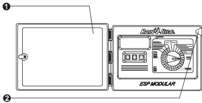
The ESP Modular controller is an irrigation timing device for residential and light commercial use.
The ESP Modular comes in two basic models, the ESP-4Mi for indoor use and the ESP-4M for indoor or outdoor use.
The basic unit supports four valves and a master valve/pump start relay. With the addition of optional internal modules, the ESP Modular can support up to 13 valves (including an auxiliary valve), and a master valve/pump start relay.
Français
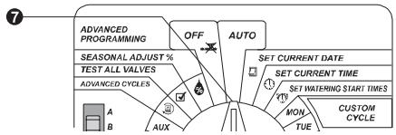
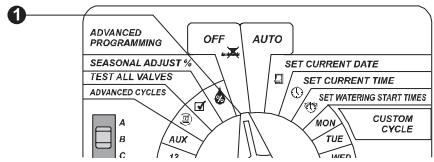
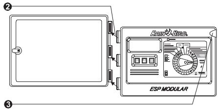
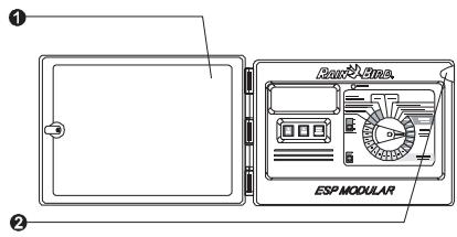
Controls and Switches
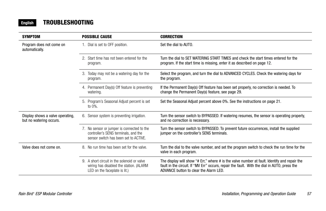
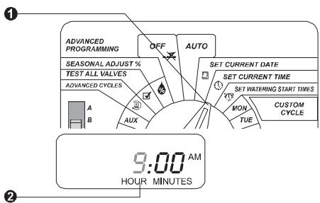
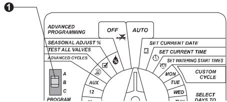
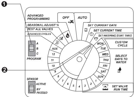
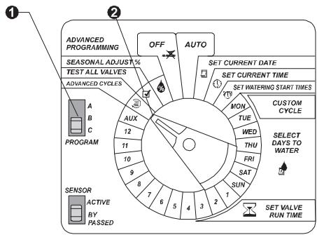
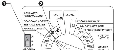
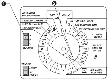
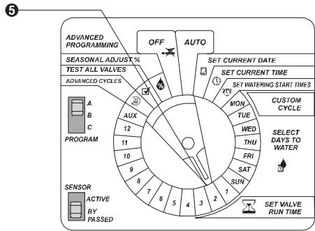
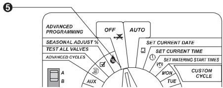
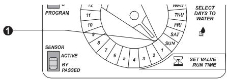
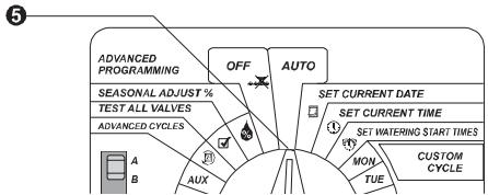
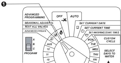
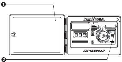
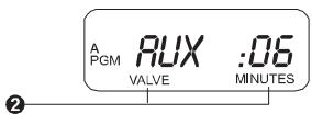
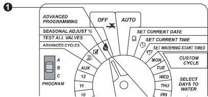
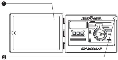
The illustration to the right shows the controls, switches, and indicators on the ESP Modular controller, including:
-
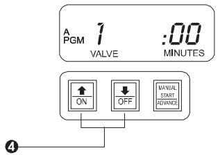
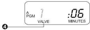
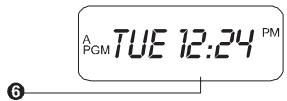
LCD Display — during normal operation, displays the time of day and day of the week; during programming, shows the results of your commands; during watering, shows the valve that is running and the minutes remaining in its run time.
-
Alarm LED — turns on when one of the following conditions occurs:
-
Watering is suspended by a sensor
- The controller senses a valve short circuit
- A programming error has been made
Français
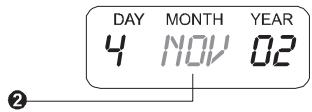
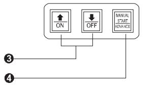
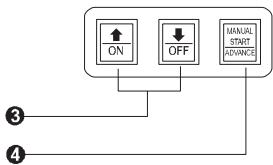
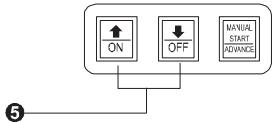
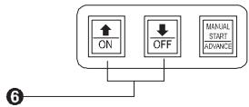
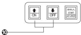
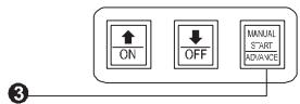
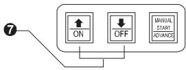
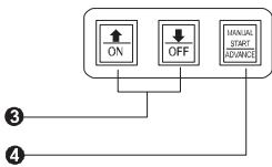
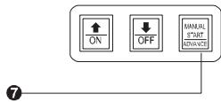
- Arrow ON-OFF Buttons - used to set the time and date, and to make program changes.
- Manual Start / Advance Button — used to start the irrigation program manually, or to manually advance watering from one station to the next.
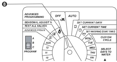
- Program Slide Switch - used to select watering program A, B, or C.
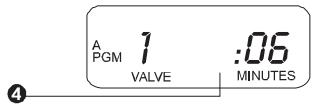
- Sensor Bypass Switch -used to tell the controller to obey or ignore input from an optional sensor.
- Programming Dial — used to turn the controller off and on, and for programming.
Français
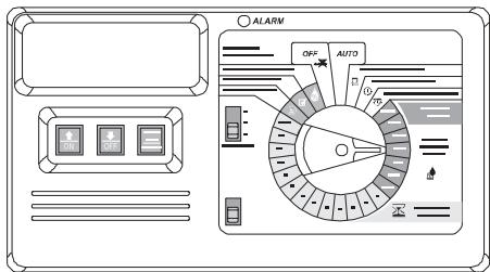
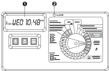
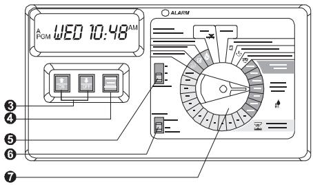
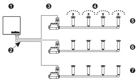
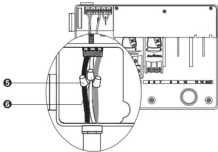
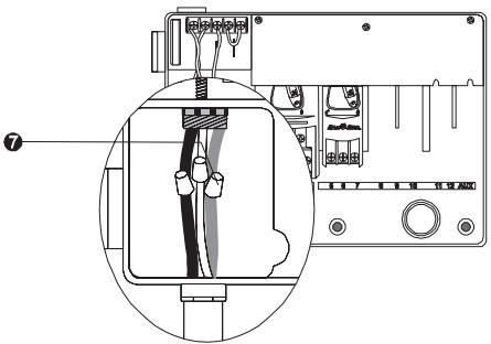
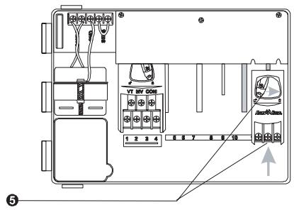
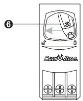
The ESP Modular controller (1) normally has several valves connected to it with electrical wires (2), as shown in the illustration.
Each valve (3) opens when it receives a signal from the controller, and the sprinklers (4) connected to the valve turn on. When these sprinklers have run for their allotted time, the controller shuts off the valve and opens the next valve in sequence.
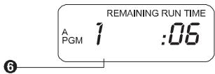
For example, the illustration shows that the first valve is currently watering (5). When this valve is finished, the controller will shut it off and start the next valve (6). In the same way, the next valve (7) will begin watering when the second valve is finished.
Français
LA PROGRAMMATION
To program the ESP Modular controller for the first time, you should complete the steps in the order they appear in this manual. For your convenience, we have provided a basic programming checklist below.
Programming Checklist
Set current date . page 9
Set current time . page 10
Select program . page 11
Set watering start times... page 12
Set watering cycle.... page 14
Set valve run times . page 18
Français
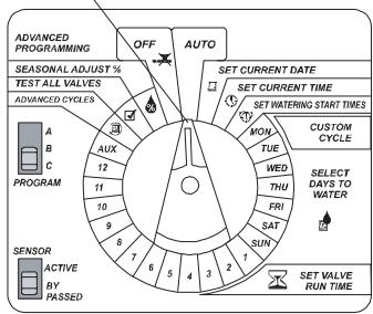
Réglage de la date

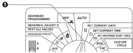
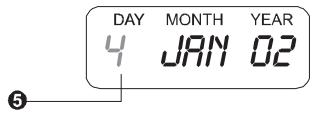
- Turn the dial to "SET CURRENT DATE."
- The display shows the day of the month, the month, and the year. The month flashes.
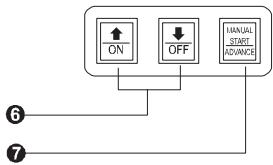
- Press or to set the current month.
- Press "MANUAL START / ADVANCE."
- The day of the month flashes in the display.
Français
- Press or to set the current day.
- Press "MANUAL START / ADVANCE."
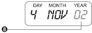
- The year flashes in the display.
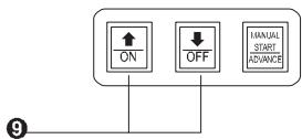
- Press or to set the current year.
- Set the dial to "AUTO."
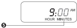
Set Current Time

- Turn the dial to "SET CURRENT TIME."
- The display shows the time of day.
The hour flashes.
Français
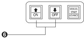
- Press or to set the current hour.
- Press "MANUAL START / ADVANCE."
- The minute digits flash in the display.
- Press or to set the current minute.
- Set the dial to "AUTO."
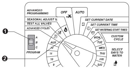
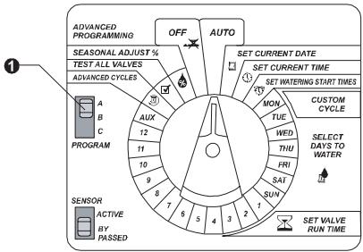
Select Program
The ESP Modular controller has three separate programs, A, B, and C. Each program can have different watering days and start times. You can program any valve to run in one or more of the three programs.
- To select a program, slide the PROGRAM switch on the front panel.
Français
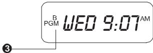
- The display briefly shows the program you selected.
- The selected program then appears on the left side of the display.
- Any programming instructions you enter, such as setting a watering start time, will apply only to the selected program.
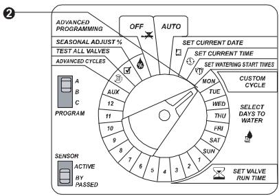
Set Watering Start Times
You can set up to four watering start times for each program. A start time is the time of day when a program begins to run. When the start time arrives, each valve in the program will run in sequence, from the lowest number to the highest. If you want to run a single valve or series of valves manually, see "Use Manual Start / Advance" on page 23.
- Select the program you want.
- Turn the dial to "SET WATERING START TIMES."

Français
- The display shows the first start time currently set for the program.
- Press or to change the start time. The time setting moves forward and backward in 15-minute increments.
- To eliminate a watering start time, press or until the "OFF" setting between 11:45 p.m. and 12:00 a.m. appears.
- If you want to set additional start times for this program, press "MANUAL START / ADVANCE" to display the next watering start time. Then repeat steps 4 through 6.
- Turn the dial to "AUTO."
A PGM
START TIME
12:00AM
HOUR MINUTES
3

PGM 15T OFF
START TIME
OFF
PGM
END
12:00AM
START TIME
HOUR MINUTES

ON
OFF
WANVAL START ADVANCES
6
Français
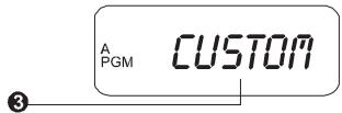
Each program can run in one of four watering cycles:
- CUSTOM waters on the days of the week you select. See the instructions below.
- ODD waters only on odd-numbered days of the month. See page 15.
- EVEN waters only on even-numbered days of the month. See page 15.
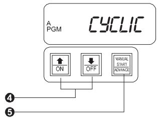
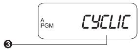
CYCLIC waters on a selected daily interval (for example, every other day, or every third day). See page16.
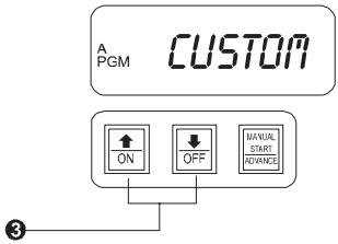
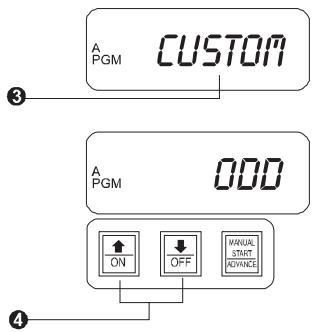
Custom Cycle

- Select the program you want.
- Turn the dial to ADVANCED CYCLES.
- "CUSTOM" should appear in the display. If it does not, press or until "CUSTOM" appears.
Français
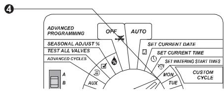
- Turn the dial to "MON."
- The display shows the day of the week and "ON" or "OFF."
- Press "ON" or "OFF" to change the setting for this day of the week.
- Turn the dial to the next day of the week. Repeat steps 5 through 7 until you have set each day of the week either ON or OFF.
- Turn the dial to AUTO.
Advanced Cycles

Odd / Even
- Select the program you want.
- Turn the dial to "ADVANCED CYCLES."
Français
- The display shows the cycle currently selected for the program.
- To change the setting, press or until "ODD" or "EVEN" appears in the display.
- Turn the dial to AUTO.
Cyclic
- Select the program you want.
- Turn the dial to "ADVANCED CYCLES."
- The display shows the cycle currently selected for the program.
Français
- To change the setting, press or until "CYCLIC" appears in the display.
- Press "MANUAL START / ADVANCE."
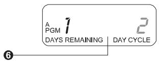
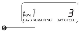
- The display shows the number of days remaining until the next watering day, and the number of days in the cycle. The DAY CYCLE flashes.
- Press or to set the number of days in the cycle (from 1 to 31). For example, if you want to water every other day, set the day cycle to "2." If you want to water every third day, set the day cycle to "3."
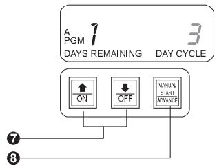
- Press MANUAL START / ADVANCE.
- The DAYS REMAINING digit flashes.
Français
- Press or to set the number of days remaining before the next watering day. "0" means that today is a watering day. If you want watering to begin tomorrow, set the days remaining to "1."
- Turn the dial to AUTO.
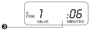
Set Valve Run Times

You can set any valve to run from 0 to 6 hours. For the first hour, you can set the run time in one-minute increments. For the remaining five hours, you can set the run time in 10-minute increments.
- Select the program you want.
- Turn the dial to valve number 1.
- The display shows the selected valve and the minutes of run time.
Français
- Press or to set the number of minutes you want the valve to run. If you do not want a valve to run during this program, set the "MINUTES" to 0.
- Turn the dial to the next station in sequence. Repeat steps 3 through 5 until you have set a run time for each valve in the program.
NOTE: If you turn the dial to the valve number of a module that is not installed in the controller, the message "NO MOD1", "NO MOD2" or "NO MOD3" appears in the display. This message indicates that there is no module installed in that valve's position.
- Turn the dial to AUTO.
Français
FONCTIONNEMENT DU PROGRAMMATEUR
After you have programmed the controller, you will normally set it to operate automatically. You can also run programs and valves manually, and you can set advanced features.
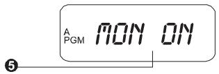
Set Controller to AUTO
- To set the controller to automatic operation, turn the dial to "AUTO." The display shows the currently selected program, the day of the week, and the time of day. The controller runs the valves according to the programs you have set.
- To turn the controller off, so no watering occurs, turn the dial to "OFF." The display shows "OFF" and the time of day.
PGM WED 10:48AM
OFF 10:48 AM
Français
Set Seasonal Adjust Percent
The seasonal adjust percent lets you increase or decrease the run times of all valves by a selected percentage, from 0 to 200 percent.
You can use this feature to cut back watering during cool winter months, or to increase watering during dry periods.
The seasonal adjustment is calculated on the normal programmed run time for each valve.
For example, if a valve is programmed to run for 10 minutes, and you set the seasonal adjustment to 80% , the valve will run for 8 minutes. If you set the adjustment to 120% , that same valve will run for 12 minutes.
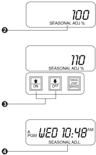
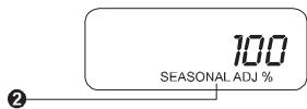
- Turn the dial to "SEASONAL ADJUST %.

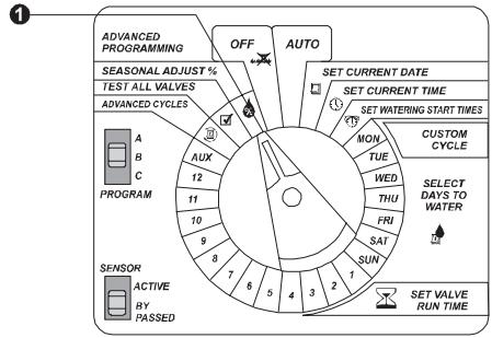
Français
- The display shows the current seasonal adjustment percentage.
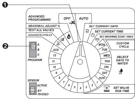
- Press or to set the percentage, in 10-point increments.
- Turn the dial to "AUTO." When the seasonal adjust percent is set higher or lower than 100 percent, the display shows "SEASONAL ADJ."
Français
- Turn the dial to AUTO.
- Select the program you want to run manually.
- Press MANUAL START / ADVANCE to start the selected program.
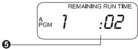
- The display shows each valve in the program, along with its remaining run time. As each valve finishes, the next valve in sequence will begin running.
Français
- To cancel all programs currently selected to run, turn the dial to OFF for three seconds. Then return the dial to AUTO.
Run Valve(s) Manually
- Turn the dial to the valve number you want to run. Make sure the valve has a run time greater than 0 in the selected program.
- If the valve has a zero run time, either select a different program or press to set a non-zero run time. This run time will then become part of the program.

Français
- Press MANUAL START / ADVANCE to start the selected valve.
- The valve number blinks in the display to show that it is running.
- If you want to adjust the run time for the manual valve operation, turn the dial to AUTO.
- The display shows the valve number currently running, along with its remaining run time.
- Press or to adjust the remaining run time for the valve. These adjustments will not be reflected in the programmed run time for this valve. If you want to run additional valves, repeat steps 1 through 7. Each valve you select will run when the previous valve has ended.
- To cancel all valves currently selected to run, turn the dial to OFF for three seconds. Then return the dial to AUTO.
Français
Test des vannes
The ESP Modular controller has a built-in test program. This program automatically runs each valve that has a non-zero watering time assigned to it.
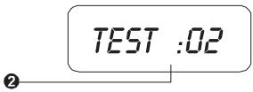
- Turn the dial to "TEST ALL VALVES."
- The display shows "TEST" and the default run time of 2 minutes.
- To change the default run time, press or .
- Press "MANUAL START / ADVANCE" to begin running the test program. Then turn the dial to AUTO.
- While the test program is running, the display shows the valve number currently operating, along with its remaining run time.
Français
- The controller will run each valve in numerical sequence and then return to AUTO mode to await the next scheduled start time. Any valve that has been set to a 0 run time will be skipped during the test program.
- To advance through the valves faster, press "MANUAL START / ADVANCE."
- To cancel the test program, turn the dial to OFF for three seconds. Then turn the dial back to AUTO.
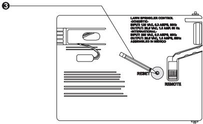
Reset Controller
The reset function can be used to "unlock" the controller's microprocessor in case of a blank/scrambled display or abnormal conditions. Resetting will not erase time, date or program information. If the reset button is pressed while the controller is irrigating, the existing program will be halted and irrigation will resume at the next program start time.
Français
- Open the cabinet door.
- Open the front panel by grasping the crescent-shaped finger hold on the top right side of the cabinet. Swing the front panel to the left.
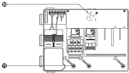
- Locate the RESET button on the back of the front panel. Using the tip of a pencil or other pointed object, press and hold the RESET button. While the button is pressed, the display will be blank.
- Close the front panel by swinging it back to the right. Turn the dial to AUTO.
PGM TUE 12:00 AM
Français
Use "Hidden" Functions
The ESP Modular controller includes several additional functions that do not correspond to dial and switch settings on the front panel. These "hidden" functions are described on the following pages.
Permanent Day(s) Off
In some areas, watering is prohibited on specific days of the week. If you are using an ODD/EVEN or CYCLIC watering cycle, you can set these days off so you won't violate watering restrictions.
- Select a program that has an ODD/EVEN or CYCLIC watering cycle (not a CUSTOM cycle).
- Turn the dial to the day of the week you want to turn OFF.
- Press OFF. "DAY ALWAYS OFF" scrolls across the display. Watering will never occur on this day of the week, regardless of the watering cycle or program.
- To turn the day of the week back on, press ON.
- Turn the dial to AUTO.
Français
Setting the Pump / Master Valve Operation
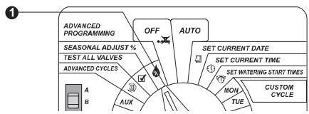
The controller has one master valve (MV) terminal on its main Module 0. In some systems, a booster pump is connected to the MV terminal and needs to operate with certain zones and not in others. The default is for all stations to have the MV circuit ON. To program MV circuit /pump operation:
- Turn the dial to "Seasonal Adjust%".
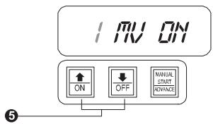
- Press and hold the MANUAL START/ADVANCE button for three (3) seconds until "SET MV" is displayed briefly.
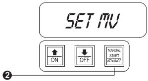
- The display will then show the station number, "MV" and a flashing "ON" or "OFF" (Default is ON for all stations).
- A. Press "OFF" or "ON" to assign master valve/pump operation to the specific station.
B. Press the ADVANCE button. This toggles between selecting the station number and MV settings.
Français
- Press the or buttons to select the next station and press the ADVANCE button.
- Repeat steps 4 and 5 for all necessary stations.
- Tum the dial to "AUTO" to finalize the master valve program by station.
Français
Délai programmable entre les stations
This feature allows the user to add a time delay between when one station turns off and the next station turns on. This is very useful for systems with pump stations that have slow recovery time or systems with slow closing valves.
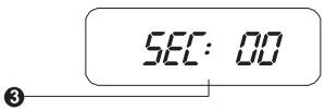
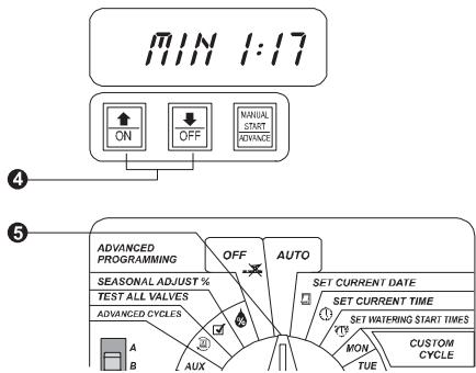
The user can set a delay between stations for each program. The delay can be from 0 seconds (default) to nine hours. The first 5 minutes can be set in 1-second increments, and the remaining time in 1-minute increments.
To set a delay between stations:
- Turn the dial to the OFF position.
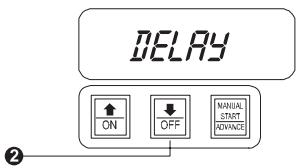
- Press and hold the "OFF" key for 3 seconds until the LCD shows "DELAY".
- The display will show the current delay between stations. Default is 0.
Français
- Use the or keys to increase or decrease the delay time you need. The example shows a delay of 1 minute and 17 seconds.
- Turn the dial back to AUTO.
Français
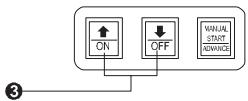
Auxiliary Valve Operation
The auxiliary valve terminal on the ESP Modular controller can operate in one of two ways. First, it can operate like a normal sprinkler valve. Second, it can be programmed so that it is not affected by a rain sensor. When programmed this way, the auxiliary terminal can be used to connect equipment such as garden lighting or patio fountains.
NOTE: To use the auxiliary valve, you must have a module installed in the third expansion slot in the controller cabinet. You can move any three-valve expansion module into this slot, and connect the appropriate field wires. See page 53 for instructions.
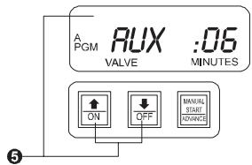
- Turn the dial to "AUX."
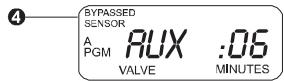
- The display shows the AUX valve and any minutes of run time assigned to the valve.
- Momentarily press AND at the same time for half a second.

Français
NOTE: The interval for pressing and to activate this feature is shorter than all the other "hidden" features. If you press both buttons for longer than half a second, the change can easily move back to the original setting.
- The display shows "BYPASSED SENSOR," indicating that the auxiliary valve is no longer affected by the rain sensor.
- To return the auxiliary valve terminal to normal operation, repeat steps 1 to 3. When you press AND at the same time for half a second, "BYPASSED SENSOR" disappears from the display, indicating that the valve IS affected by the rain sensor.
- Turn the dial to AUTO.
Français
This function clears all program information from the controller's memory. This can be useful when you want to start programming over from scratch.
NOTE: Clearing memory does not erase the current date and time, or the contractor's default program.
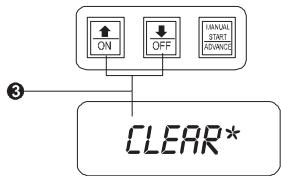
- Turn the dial to "SEASONAL ADJUST %.
- The display shows the seasonal adjustment percent that is currently set.
- Press and hold AND at the same time. The display shows "CLEAR*. Continue holding the buttons, until the display shows "CLEARED." Release AND .
- Turn the dial to AUTO.
Français
INSTALLATION
NOTE: The ESP Modular controller must be installed in compliance with local electrical codes. Indoor models must be installed indoors only. Outdoor models (with locking cabinets) may be installed either indoors or outdoors.
Select Location
- Select an area protected from vandalism, where you can easily reach the controller. We recommend mounting the controller at eye level in a utility room.
CAUTION: To minimize electromagnetic interference, select a location at least 15 feet (4,6m) away from high-draw motors, such as air conditioners or refrigerators.
Français
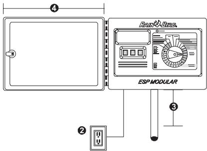
- Select a location that has access to 120 VAC / 230 VAC / 240 VAC electrical power (as required).
NOTE: Some international models use 230 VAC / 240 VAC.
- Choose a flat, stable, vertical surface. Allow enough clearance for electrical conduit and connections at the bottom of the plastic cabinet.
- Allow at least 11" of horizontal clearance so the hinged cabinet door can swing fully open to the left.
Français
Mount Controller Field Wire Entrances
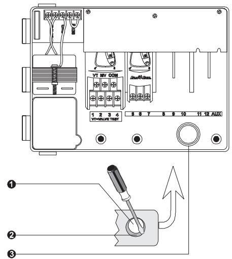
The ESP Modular has three "knockouts" available for routing valve wires, two on the underside of the cabinet, and one on the back.
- The underside of the cabinet has two knockouts sized for either a 1'' (2,6 cm) or 1' / 4'' (3,2 cm) PVC male adapter.
- To use the larger hole, turn the cabinet upside down. Place the blade of a slot-head screwdriver in the groove around the knockout. Tap the handle of the screwdriver to punch in the knockout in two places.
- To route field wires through the back of the cabinet, use the 1/4 (3,2 cm) knockout provided. Punch out the knockout, as described in step 2.
Français
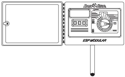
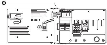
Hanging the Controller
Before you mount the controller, we recommend you remove the door and face panel. Although these steps are not absolutely necessary, they will make installation easier.
- If necessary, unlock the door with the supplied key. Open the door of the cabinet and swing it to the left.
- Lift the door off the hinges.
- Open the face panel by grasping the crescent-shaped finger hold on the top right side of the cabinet. Swing the face panel to the left.
- Pull out the cabinet slightly and slip the face plate hinge pin out of the socket on the cabinet.
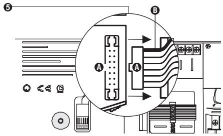
- Disconnect the ribbon cable from the back of the front panel by gently pulling the connector straight up from the socket.
CAUTION: When reassembling the connector please observe the keyed orientation of the connector (A). If correctly connected, the red mark (B) on the cable will be facing upwards.
Français
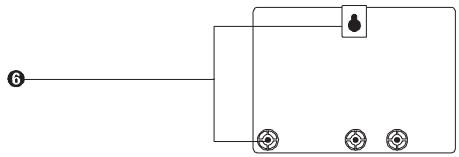
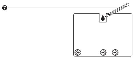
- The ESP Modular controller has a single keyhole slot at the rear top of the cabinet. At the bottom of the cabinet are three circular mounting holes. Mount the controller so that at least one of the bottom holes lines up with a wall stud or other solid surface.
- Hold the controller at eye level against the mounting surface. Use a pencil to mark the position of the top key hole slot and one or more of the bottom holes. Then put the controller cabinet aside.
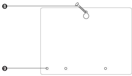
- Drive an appropriate fastener for the type of wall into the mark for the key-hole slot.
- Drill or tap a pilot hole on the mark for the lower mounting hole(s). DO NOT drive a fastener into these locations yet.
Français
- Hang the controller by the keyhole slot. Make sure the fastener is well up in the narrow part of the keyhole.
- Drive the appropriate fastener(s) into the lower mounting hole(s). Verify that the cabinet is secure.
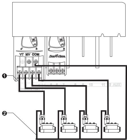
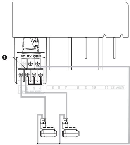
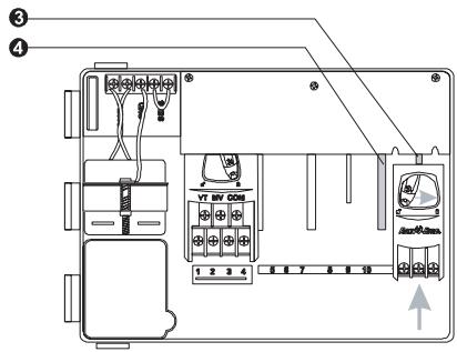
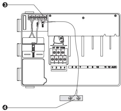
Connect Field Wiring Station Valve Wiring
- Connect each valve by its own separate power wire to one of the numbered screw terminals, as shown in the illustration.
- Connect a common wire to one of the leads on each valve. Connect the other end of the common wire to the COM terminal. Wires used to connect the valves must be code-approved for underground installation.
Français
NOTE: To use the auxiliary valve terminal, you must have a module installed in the third expansion slot in the controller cabinet. You can move any three-valve expansion module into this slot.
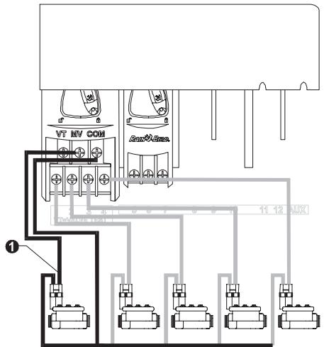
Master Valve / Pump Start Relay Wiring
NOTE: Complete this section only if your system requires a master valve (an automatic valve installed on the mainline pipe upstream from the station valves) or a pump start relay. The controller does not provide main power for a pump.
- Connect the master valve or pump start relay wiring to the controller as shown in the illustration.
Français
Jumper Setting for Unused Stations
- CAUTION: To prevent pump damage when using a pump start relay, use a jumper to connect unused stations to a station that is being used.
If unused stations are not jumpered and they are accidentally turned on, the pump may operate with no flow (dead-head). Dead-heading could cause the pump to overheat or burn out.
Français
NOTE: To connect main power wires on the ESP-4M outdoor controller, see the instructions on page 47.
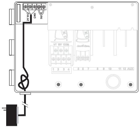
The ESP-4Mi controller has an external transformer that reduces standard supply voltage to 24 VAC to operate the sprinkler valves. You will need to connect this transformer to the terminals in the controller cabinet.
CAUTION: To prevent electrical shock and potential damage to the transformer, DO NOT plug in the transformer until you have connected its cable to the controller.
All electrical connections and wiring runs must be made according to local building codes.
Français
- Make sure the transformer is NOT plugged in.
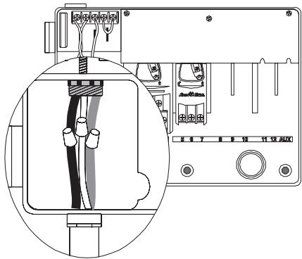
- Feed the three transformer wires through the bottom left hole in the cabinet. Then pull about 12^ of the cable up into the cabinet.
- Tie a loose overhand knot in the cable just inside the controller to prevent any strain on the connector terminals.
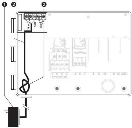
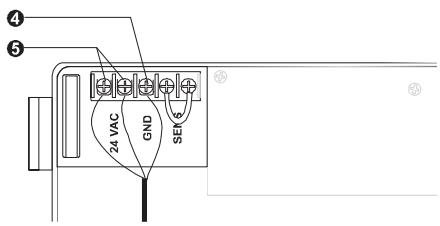
- On the horizontal terminal strip at the top of the controller cabinet, connect the green wire to the "GND" terminal.
- Connect one of the remaining two wires to a "24 VAC" terminal. Connect the other wire to the second "24 VAC" terminal. Connect either wire to either 24 VAC terminal; polarity of these wires is not important.
Français
- Verify that all connections are secure. Then plug the transformer into any standard three-pronged grounded electrical outlet.
ESP-4M Outdoor Controller
NOTE: To connect main power wires on the ESP-4Mi indoor-only controller, see the instructions on page 45.
The ESP-4M controller has an internal transformer that reduces standard supply voltage (120 VAC in U.S. models; 230 VAC / 240 VAC in international models) to 24 VAC to operate the valves connected to the controller. You will need to connect power supply wires to the transformer's three wires.
WARNING: To prevent electrical shock, make sure all supply power is OFF before connecting these wires. Electrical shock can cause severe injury or death.
Français
CAUTION: All electrical connections and wiring runs must be made according to local building codes.
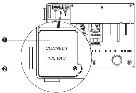
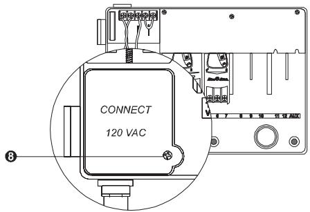
- With the door and face panel removed, locate the high-voltage compartment in the lower left corner of the controller cabinet.
NOTE: Some international versions use 230 VAC / 240 VAC. 240 VAC models have factory provided connection.
- Remove the screw on the right edge of the compartment cover. Then pull the cover open to expose the transformer's primary input wires.
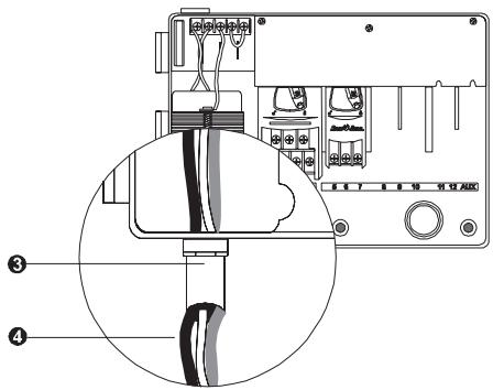
3 Attach a 1 / 2 (1,3 cm) conduit fitting to the bottom entrance of the high-voltage compartment. Then attach conduit to the fitting.
- Bring three supply wires from the power source through the conduit into the high-voltage compartment. Strip the insulation from the incoming wires to expose about 12 (1,3 cm) of bare wire.
Français
- Using a code-approved wire connector, connect the wires as follows:
- On 120 VAC models (U.S.), connect the black supply wire ("hot") to the black transformer wire.
-
On 230 VAC models (international), connect the brown supply wire ("hot") to the brown transformer wire.
240 VAC models have factory provided connection.
-
On 120 VAC models (U.S.), connect the white supply wire ("neutral") to the white transformer wire.
On 230 VAC models (international), connect the blue supply wire ("neutral") to the blue transformer wire.
Français
- On 120 VAC models (U.S.), connect the green supply wire ("ground") to the green transformer wire.
On 230 VAC models (international), connect the green-with-yellow-stripe supply wire ("ground") to the green-with-yellow-stripe transformer wire.
NOTE: The ground wires MUST be connected to provide electrical surge protection.
- Verify that all connections are secure. Then close the cover of the high-voltage compartment and secure it with the screw.
Français
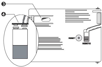
Remote Panel Programming
Installing a 9-Volt alkaline battery in the ESP Modular controller will allow you to program the controller with the faceplate disconnected from the cabinet.* The battery is NOT required to maintain program information.
- Open the cabinet door.
- Open the front panel by grasping the crescent-shaped finger hold on the top right side of the cabinet. Swing the face panel to the left.
- Locate the battery compartment on the rear of the front panel.
- If you are replacing a battery, pull the old battery out of the compartment and remove the connector from the battery terminals. Install the connector on the new battery.
Français
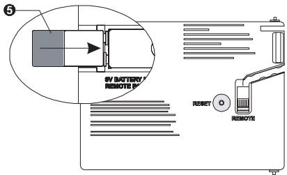
- Slide the battery into the compartment and close the front panel.
*NOTE: With a battery installed and the front panel disconnected from the cabinet, you can program run times to any station and any module. However, once AC is applied, run times for a nonexistent module will be erased.
Français
Installation d'un module
Optional modules for the ESP Modular controller provide terminals for up to nine additional valves.
You can install optional modules in any open position in the cabinet. The valve numbers associated with each terminal (e.g., 5, 6, 7) are molded into the cabinet.
NOTE: If you wish to bypass a rain sensor with the auxiliary valve feature, you must have a module installed in the far right slot in the controller cabinet.
- Open the cabinet door.
- Open the front panel by grasping the crescent-shaped finger hold on the top right side of the cabinet. Swing the face panel to the left.
- Locate an open slot in the cabinet.
- Make sure the lever on the module is in the unlocked position (pointing to the left). Place the module in the slot between the plastic rails.
Français
- Push the module toward the top of the cabinet. Then slide the lever to the locked position (to the right).
- To remove a module, slide the lever to the unlocked position and pull the module out of the slot.
NOTE: You can install or remove any modules with or without AC voltage connected. The modules are "hot swappable."
Français
Connecting the RSD Rain Sensor
NOTE: The Rain Bird® Rain Check sensor and Moisture Sensor must be wired by interrupting the common.
Complete this section only if your system has an automatic sensor.
If you are not connecting a sensor to the controller, make sure the supplied jumper is installed on the two SENS terminals on the controller's terminal strip.
- Open the cabinet door.
- Open the face panel by grasping the crescent-shaped finger hold on the top right side of the cabinet. Swing the face panel to the left.
- Most sensors have two wires or two terminals designed to be connected to the valve common wire. Instead of connecting to the valve common wire, connect these wires or terminals to the "SENS" terminals on the ESP Modular controller.
Français
- Route the pair of wires out of the controller cabinet and connect them to the sensor system.
- Follow the sensor system's directions for placing and connecting moisture probes, setting the rain shutoff level, and making final adjustments.
| SYMPTOM | POSSIBLE CAUSE | CORRECTION |
| Program does not come on automatically. | 1. Dial is set to OFF position. | Set the dial to AUTO. |
| 2. Start time has not been entered for the program. | Turn the dial to SET WATERING START TIMES and check the start times entered for the program. If the start time is missing, enter it as described on page 12. |
| 3. Today may not be a watering day for the program. | Select the program, and turn the dial to ADVANCED CYCLES. Check the watering days for the program. |
| 4. Permanent Day(s) Off feature is preventing watering. | If the Permanent Day(s) Off feature has been set properly, no correction is needed. To change the Permanent Day(s) feature, see page 29. |
| 5. Program's Seasonal Adjust percent is set to 0%. | Set the Seasonal Adjust percent above 0%. See the instructions on page 21. |
| Display shows a valve operating, but no watering occurs. | 6. Sensor system is preventing irrigation. | Turn the sensor switch to BYPASSED. If watering resumes, the sensor is operating properly, and no correction is necessary. |
| 7. No sensor or jumper is connected to the controller's SENS terminals, and the sensor switch has been set to ACTIVE. | Turn the sensor switch to BYPASSED. To prevent future occurrences, install the supplied jumper on the controller's SENS terminals. |
| Valve does not come on. | 8. No run time has been set for the valve. | Turn the dial to the valve number, and set the program switch to check the run time for the valve in each program. |
| 9. A short circuit in the solenoid or valve wiring has disabled the station. (ALARM LED on the faceplate is lit.) | The display will show "# Err," where # is the valve number at fault. Identify and repair the fault in the circuit. If "MV Err" occurs, repair the fault. With the dial in AUTO, press the ADVANCE button to clear the Alarm LED. |
TROUBLESHOOTING
Battery, installing 9-Volt, 51
Clear memory, 36
Controls and Switches 5
alarmLED,5,59
LCD display, 5
Day always off, 29
Hidden functions, 29
auxiliary valve operation, 34
clear memory, 36
permanent day(s) off, 29
programmable delay between stations, 32
setting the pump/master valve operation, 30
Installing
battery, 51
controller, 39
field wiring, 42
location, 37
module, 53
rain sensor, 55
Français
Installation
cables, 42
I'emplacement, 37
module, 53
pile, 51
programmateur, 39
sonde plue, 55
Mémoire, Effacement, 36
Mode AUTO, 20
Module
installation, 53
vanneauxiliale,34
Jumper, SENS terminals, 55
Manual Watering, 23
Memory, clear, 36
Module
auxiliary terminal, 34, 43, 53
installing, 53
Operating controller, 20
Permanent Day(s) off, 29
Programmable Delay Between Stations, 32
Programming
date, 9
time, 10
select program, 11
watering start times, 12
watering cycle, 14
watering duration, 18
Rain sensor, 55
Remote Panel Programming, 51
Reset controller, 27
Seasonal Adjust, 21
SENS terminals, 55
Setting the Pump/Master Valve Operation, 30
Test valves, 26
Français
Test des vannes, 26
Transformateur, 45
Vanne
auxiliaire, 34
testdes,26
VanneAuxiliaire,34
The ESP Modular controller has an internal, non-replaceable lithium battery that has a shelf life of ten years. Discard the used controller in compliance with local laws as you would any electronic component or battery.
This equipment has been tested and found to comply with the limits for a Class B digital device, pursuant to Part 15 of the FCC Rules. These limits are designed to provide reasonable protection against harmful interference in a residential installation.
This equipment generates, uses, and can radiate radio frequency energy and, if not installed and used in accordance with the instructions, may cause harmful interference to radio communications. However, there is no guarantee that interference will not occur in a particular installation.
If the equipment does cause harmful interference to radio or television reception, which can be determined by turning the equipment off and on, the user is encouraged to try to correct the interference by the following measures:
Reorient or relocate the receiving antenna.
- Increase the separation between the equipment and receiver.
- Connect the equipment into an outlet on a circuit different from that to which the receiver is connected.
- Consult the dealer or an experienced radio/TV technician for help.
Changes or modifications not expressly approved by Rain Bird Corporation, could void the user's authority to operate the equipment.
This product was FCC certified under test conditions that included the use of shielded I/O cables and connectors between system components. To be in compliance with FCC regulations, the user must use shielded cables and connectors and install them properly.
RAIN BIRD
Rain Bird Corporation
970 W. Sierra Madre
Azusa, California 91702, U.S.A.
626-963-9311
Rain Bird International, Inc.
145 North Grand Avenue
Glendora, CA 91741 U.S.A.
626-963-9311
Rain Bird Europe
900 rue-Ampere, BP 72000
13792 Aix-en-Provence CEDEX 3 FRANCE.
(33) 04 42 24 44 61
Technical Services for U.S. and Canada only:
(800) RAINBIRD
www.rainbird.com