
WS-PRO2 - Weather Station RAIN BIRD - Free user manual and instructions
Find the device manual for free WS-PRO2 RAIN BIRD in PDF.


| Product Type | Weather Station for golf course and irrigation management |
| Brand | Rain Bird |
| Model | WS-PRO2 |
| Monitored Parameters | Rainfall, wind speed and direction, air temperature, relative humidity, solar radiation |
| Power Supply Options | AC power (100-240 VAC to 24 VDC), solar panel (10W or 20W), or integrated battery (7 Ah standard, optional 24 Ah) |
| Communication Options | Direct RS-232, phone modem, short-haul modem, radio, cellular, Wi-Fi |
| Data Logger | CR1000-based with internal lithium battery for clock and SRAM backup |
| Enclosure | Weather-resistant, with desiccant packs for humidity control |
| Sensor Maintenance | Weekly: clean rain gauge screen; monthly: clean pyranometer and inspect wind sensor; quarterly: clean radiation shield; yearly: replace bearings, reed switch, and RH chip |
| Safety Precautions | Keep away from power lines; use proper grounding; handle lithium battery with care; follow local electrical codes |
| Spare Parts | RH chip (HMP60-ETS), wind sensor bearings, reed switch, potentiometer, desiccant packs, enclosure gasket |
| Software Compatibility | Rain Bird SmartWeather, Cirrus, Nimbus II, Stratus II central control systems |
| Installation Requirements | Concrete base (0.6 m³), pole grounding, siting away from obstructions (10x height for wind, 9 m diameter for temp/RH) |
Frequently Asked Questions - WS-PRO2 RAIN BIRD
User questions about WS-PRO2 RAIN BIRD
0 question about this device. Answer the ones you know or ask your own.
Ask a new question about this device
Download the instructions for your Weather Station in PDF format for free! Find your manual WS-PRO2 - RAIN BIRD and take your electronic device back in hand. On this page are published all the documents necessary for the use of your device. WS-PRO2 by RAIN BIRD.
USER MANUAL WS-PRO2 RAIN BIRD
WS-PRO2 Golf Course Weather Station
Installation, Operation,
Maintenance, and
Troubleshooting Manual
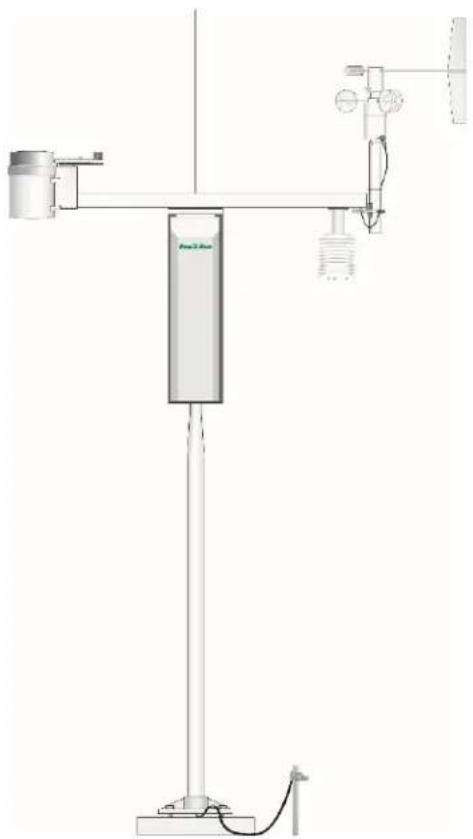
natural_image
Technical diagram of a scientific instrument with labeled components and wiring (no readable text or symbols)Table of contents
- Introduction 1
- Precautions 2
- Initial inspection 3
- QuickStart 6
4.1 User-supplied tools 6
4.2 Supplies for power and communications options 8
- Siting and exposure 10
5.1 Wind speed and direction 10
5.2 Temperature and relative humidity 11.
5.3 Solar radiation 11
- Installation 12
6.1 Base foundation installation 12....
6.2 Pole installation 14
6.2.1 Pole grounding 16
6.3 Enclosure installation 17
6.4 AC power installation procedure 18
6.5 Crossarm installation procedure 20
6.6 Sensor installation 21
6.6.1 RH and temperature radiation shield installation procedure 22
6.6.2 034B Wind Sensor (wind sensor option -MW) 24
6.6.3 WindSonic 2-D Ultrasonic Wind Sensor (wind sensor option -GW).... 26
6.6.3.1 Changing the jumper 26
6.6.3.2 WindSonic attachment to crossarm 28
6.6.4 Rain gauge 30
6.6.5 Pyranometer 31
6.6.6 107 or 108 soil temperature sensor (optional) 33
6.6.7 Sensor connections 33
6.6.8 Sensor verification and clock set 34
6.7 Communications peripherals 35
6.7.1 Direct connect to WS-PRO2 station 35
6.7.2 Phone modem 36
6.7.2.1 Internal installation of phone modem 37
6.7.2.2 External installation of phone modem 38
6.7.3 Short-haul modem 38
6.7.3.1 Internal installation of short haul modem 38
6.7.3.2 External installation of short haul modem 40
6.7.4 Radio 41
6.7.4.1 Example radio configuration and power usage 42
6.7.4.2 Internal installation of the radio 42
6.7.4.3 External installation of the radio 44
6.7.4.4 Base radio installation 50
6.7.5 WS-PRO2 cell phone accessory kit 51
6.7.5.1 Cellular modems available from Campbell Scientific 51....
6.7.5.2 Power considerations 52
6.7.5.3 Antenna 52
6.7.5.4 Establishing cellular service and configuring the cellular modem.... 52
6.7.5.5 Internal installation of the cellular modem 52
6.7.5.6 External installation of a cellular modem 53
6.7.6 NL241 Wi-Fi accessory kit 55
6.7.6.1 Antenna 55
6.7.6.2 Power considerations 55
6.7.6.3 Internal installation of Wi-Fi modem 55
6.7.6.4 External installation of the Wi-Fi modem 56
6.8 Lightning rod installation 57
6.9 Solar panel installation 59
6.10 Battery installation 61
6.11 Restraining cables 62
6.12 Sealing and desiccating the enclosure 63
6.13 WS-PRO2 software 64
7. Maintenance and troubleshooting 65
7.1 Maintenance 65
7.1.1 Pole maintenance 65
7.1.2 Power supply maintenance 65
7.1.3 Desiccant 66
7.1.4 Sensor maintenance 66
7.1.4.1 Procedure for removing RH chip 69
7.1.5 Data logger module 69....
7.2 Troubleshooting 7.0
7.2.1 No response using the CR1000KD keypad 70
7.2.2 No response from data logger when using a communications peripheral.71...
7.2.3 NAN, ±INF, or unreasonable results displayed in a variable or stored in a data table 72.
7.2.4 WindSonic1-ET diagnostic codes 72
8. Schematics of connectors 73
8.1 Sensor schematics 73
8.2 Power schematics 78
8.3 Communications modems schematics 78
9. References 79
Appendix A. Grounding recommendations 80
A.1 Grounding system installation 80.
A.1.1 Ground resistance 80
A.1.2 Installation requirement 80
A.1.3 Ground rod stacking 81
A.2 Grounding system designs 82
A.2.1 Design "Y" 82
A.2.2 Design "Y" (alternate) 84
A.2.3 Grounding plate design 85
Appendix B. Determining True North and wind sensor orientation 87
B.1 Online magnetic declination calculator 89
Appendix C. PS24 24 Ah power supply with 10 x 12 inch enclosure 91
C.1 PS24 components 91
C.2 PS24 installation 93
Appendix D. WS-PRO2 maintenance log 103
1. Introduction
The Rain Bird WS-PRO2 Weather Station, when used in conjunction with the Rain Bird Cirrus, Nimbus II, or Stratus II Central Control system, provides the irrigation professional with a powerful tool to aid in the growing of lush, healthy, green turf grass, while conserving important resources, such as water, power, etc.
Rain Bird SmartWeather software interrogates the WS-PRO2 weather station to retrieve information that has been gathered on a daily basis of the climatic conditions that affect the irrigation application for the area.
The SmartWeather software subjects the climatic information that it gathers to a version of the modified Penman Equation. The Penman Equation has been proven through over 35 years of university research to be one of the most reliable predictors of turf grass water use requirements.
The weather station monitors the following climatic conditions:
- Rainfall
• Wind speed and direction - Air temperature
- Relative humidity
- Solar radiation
The standard WS-PRO2 configuration includes sensors to monitor these conditions, a data logger to capture this data, a modem to communicate the information to the SmartWeather software located on the central control computer, and a power supply.
2. Precautions
- READ AND UNDERSTAND the Safety section at the back of this manual.
- DANGER: If any part of the weather station comes in contact with power lines, you could be killed. Contact local utilities for the location of buried utility lines before digging or driving ground rods.
- Avoid dangerous electrical accidents when using the AC power option by locating the transformer remotely and burying a low voltage line to the station. The low voltage will carry up to 152 m (500 ft) on an 18 AWG power cable.
- Carefully handle the WS-PRO2 components during transport, installation, and cleaning.
- Leave the 034B wind vane in the protective cardboard sleeve until it's ready to be installed.
- Ensure to remove the yellow cap from the RH and temperature sensor, the red or green cap from the pyranometer, and the rubber band from the tipping bucket mechanism. Save the caps for shipping or storing the sensors.
- When connecting cables to the enclosure panel, ensure that each plug is completely seated on the connector and the locking ring is turned a quarter revolution clockwise. Failure to seat the plug completely could cause corrosion and water damage to both the enclosure and the cable.
- WARNING: Misuse of the lithium battery in the data logger or installing this lithium battery improperly can cause severe injury. It is a fire, explosion, and severe burn hazard! Do not recharge, disassemble, heat above 100 °C (212 °F), solder directly to the cell, incinerate, nor expose contents to water. Lithium batteries need to be disposed of properly. Refer to Data logger module (p. 69) for more information.
3. Initial inspection
Immediately upon receipt of your shipment:
- Open shipping carton(s). Solar panel and radio frequency (RF) items (if any) may be packed in a separate box.
- Set the large weather station carton down lengthwise on a floor or table top.
- Position the box as shown in FIGURE 3-1 (p. 3).
- Cut the tape along the edge of the lower flap first (FIGURE 3-1 (p. 3)).
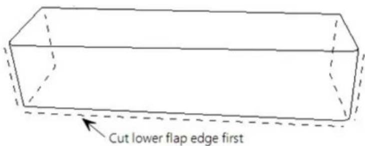
FIGURE 3-1. Cut flap packing tape
- Cut the tape around the remaining flaps ensuring to only cut one layer deep.
- Lift up the cardboard flaps exposing the top layer of foam (FIGURE 3-2 (p. 3)).
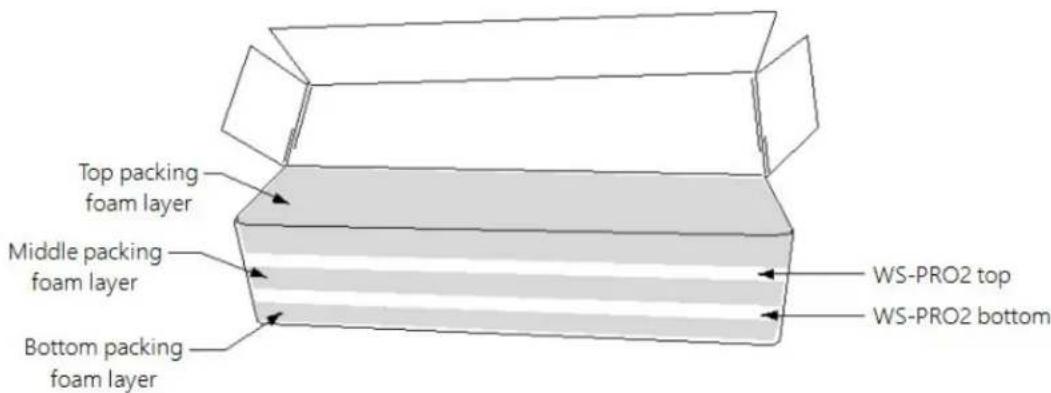
FIGURE 3-2. Shipping box packaging
- Check contents against invoice and shipping checklist (FIGURE 3-3 (p. 4), FIGURE 3-4 (p. 5)) and contact Campbell Scientific immediately about any shortages.
- Securely tape box shut if transporting entire station to another site.
- If at the main site, remove communications components that are installed at the calling computer. Repackage remaining components for transport to field site.
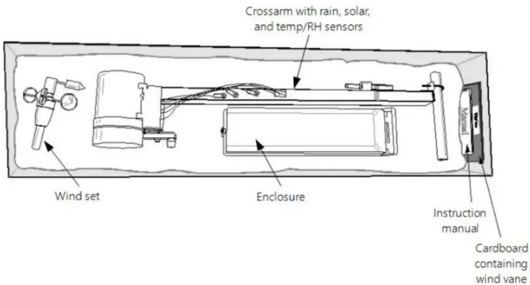
FIGURE 3-3. WS-PRO2 with the Met One 034B-ETM Wind Sensor, top layer
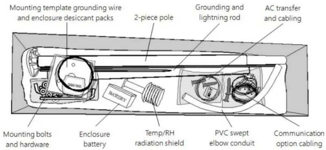
FIGURE 3-4. WS-PRO2, bottom layer
4. QuickStart
In the office, several days prior to the planned installation date, do the following:
- Collect tools (User-supplied tools (p. 6))
- Research site (Siting and exposure (p. 10))
- Install data logger support software (WS-PRO2 software (p. 64))
Once on site, do the following:
- Locate suitable site (Siting and exposure (p. 10)).
- Prepare concrete base and allow the concrete base to cure a minimum of seven days (Base foundation installation (p. 12))
- Install the WS-PRO2 pole (Pole installation (p. 14)).
- Place instrumentation enclosure on the WS-PRO2 pole, slide the enclosure to the top of the pole, and secure it with the correct orientation (Enclosure installation (p. 17)).
- Install the crossarm and sensors (Crossarm installation procedure (p. 20) and Sensor installation (p. 21)).
4.1 User-supplied tools
The following tools are used for the base and pole installation.
Shovel
Rake
Open end wrenches: 10 mm (3/8 in), 11 mm (7/16 in), 13 mm (1/2 in), two 14 mm (9/16 in)
Magnetic compass
2 m (6 ft) step ladder
Tape measure: 4 to 6 m (12 to 20 ft)
Claw hammer
Level: 60 to 90 cm (24 in to 36 in)
Hand saw
Materials for concrete form:
(4) 2.5 cm x 5 cm x 30 cm (1 in x 2 in x 12 in) stakes
(2) 5 cm x 10 cm x 240 cm (2 in x 4 in x 96 in) lumber
(12) 8p double-head nails
(8) 16p double-head nails
6 m (20 ft) form wire
0.5 m (0.5 yard) concrete
Concrete trowel, edger
Electrical fish tape or 6 m (20 ft) of small diameter rope
Wheelbarrow
The following tools are needed for instrumentation and maintenance.
Lock and key for enclosure
Magnetic declination angle
Magnetic compass
Straight bit screwdrivers (small, medium, large)
Phillips-head screwdrivers (small, medium)
Small diagonal side-cutters
Needle-nose pliers
Wire strippers
Pocket knife
Calculator
Volt / ohm meter
Electrical tape
2 m (6 ft) step ladder
Station manuals
Station log and pen
Open end wrenches: 10 mm (3/8 in), 11 mm (7/16 in), 13 mm (1/2 in), 14 mm (9/16 in), 24 mm (15/16 in)
Socket wrench and 11 mm (7/16 in) deep well socket
Adjustable wrench
Pliers
Conduit and associated tools (as required)
Felt-tipped marking pen
Claw hammer
Pipe wrench, 305 mm (12 in)
Handheld drill/driver with 10 mm (3/8 inch) hex driver bit
Drill with 6 mm (7/32 in) drill bit
4.2 Supplies for power and communications options
AC Power
Wire, conduit, and junction boxes as needed (FIGURE 4-1 (p. 8)).
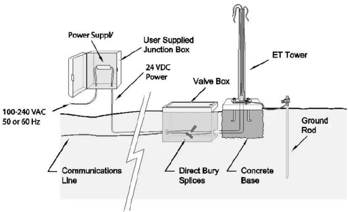
FIGURE 4-1. WS-PRO2 pole installation with currently-available AC power option
NOTE:
User supplies valve box at base of station and weatherproof enclosure for transformer (FIGURE 4-1 (p. 8)).
Phone Modem
Phone modem at the central computer.
Dedicated single twisted pair with shield phone line to the weather station valve/junction box (FIGURE 4-1 (p. 8)).
Short-Haul Modem
Direct burial cable with a minimum of two-twisted pairs with shield (minimum five conductors total) to travel from the weather station to the central computer junction box. Direct burial armored cable may be required for rocky soils or rodents (Anixter pn F-02P22BPN (phone 847-677-2600)) or equivalent type cable (FIGURE 4-1 (p. 8)).
Radio
Antenna for the WS-PRO2 station.
5. Siting and exposure
DANGER:
If any part of the weather station comes in contact with power lines, you could be killed. Contact local utilities for the location of buried utility lines before digging or driving ground rods.
Selecting an appropriate site for the weather station is critical to obtain accurate meteorological data. In general, the site should be representative of the general area of interest, and away from the influence of obstructions such as buildings and trees.
The weather station should not be located where sprinkler irrigation water will strike sensors or instrument enclosure.
Some general guidelines for site selection are listed below, which were condensed from EPA (1988), WMO (1983), and AASC (1985) publications. See References (p. 79).
5.1 Wind speed and direction
Wind sensors should be located over open, level terrain, and at a distance of at least ten times (EPA) the height of any nearby building, tree, or other obstruction (FIGURE 5-1 (p. 10)).
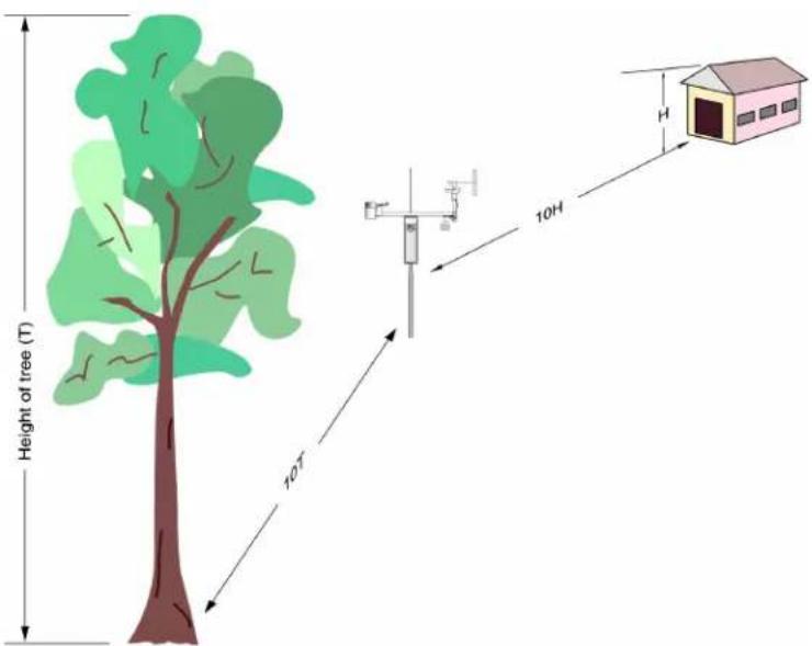
FIGURE 5-1. Effect of structure on wind flow
5.2 Temperature and relative humidity
Sensors should be located over an open, level area at least 9 m (29.5 ft) (EPA) in diameter. The surface should be covered by short grass, or where grass does not grow, the natural earth surface. Sensors should be located at a distance of at least four times the height of any nearby obstruction and at least 30 m (98.43 ft) (EPA) from large paved areas. Sensors should be protected from thermal radiation and adequately ventilated.
Situations to avoid include:
• large industrial heat sources
- rooftops
- steep slopes
- sheltered hollows
- high vegetation
- shaded areas
- swamps
- areas where snow drifts occur
- low places holding standing water after rains
5.3 Solar radiation
Pyranometers should be located to avoid shadows on the sensor at any time. Mounting it on the southernmost (northern hemisphere) portion of the weather station will minimize the chance of shading from other weather station structures. Reflective surfaces and sources of artificial radiation should be avoided.
6. Installation
6.1 Base foundation installation 12
6.2 Pole installation 14
6.3 Enclosure installation 17
6.4 AC power installation procedure 18
6.5 Crossarm installation procedure 20
6.6 Sensor installation 21
6.7 Communications peripherals 35
6.8 Lightning rod installation 57
6.9 Solar panel installation 59
6.10 Battery installation 61
6.11 Restraining cables 62
6.12 Sealing and desiccating the enclosure 63
6.13 WS-PRO2 software 64
6.1 Base foundation installation
The following components included with the WS-PRO2 are used for this installation procedure:
(3) 16 mm (5/8 in) anchor L-bolts
(9) 16 mm (5/8 in) nuts
(1) anchor template
The pole attaches to a user-supplied concrete foundation constructed as shown in FIGURE 6-1 (p.13).
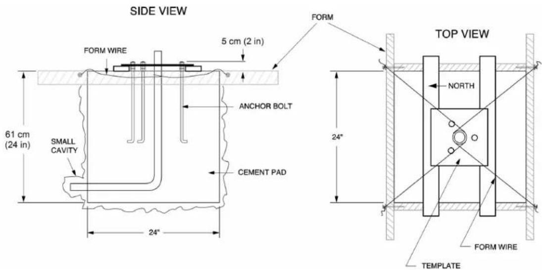
FIGURE 6-1. WS-PRO2 pole base installation
- Construct the concrete form with 5 cm x 10 cm (2 in x 4 in) lumber and 16p nails.
- Assemble the template and anchor bolts. For each bolt, place two nuts below and one nut above the template.
- Clear an area large enough to set the form at the desired elevation.
- Dig a hole 0.6 m x 0.6 m x 0.6 m (2 ft x 2 ft x 2 ft). Lighter soils may require a deeper hole.
- About 50 cm (20 in) below the top of the hole, gouge a small cavity in one wall of the hole. The cavity should be about 10 cm (4 in) deep and just large enough in diameter to insert one end of the conduit. Make certain the cavity points in the direction from which power and communications cables will come. For example, the cavity will point towards a valve box if one is being used.
- Center the form over the hole. Adjacent to the form, drive four stakes into the soil. Secure the leveled form to the stakes with the 8p nails.
- Cap the ends of the conduit with duct tape.
- Position the conduit then wire into place by securing the wire to nails in the form.
- Fill the hole and form with approximately 0.5 m (0.5 yards) of concrete. Screed the concrete level with the top of the form.
-
Center the template assembly over the conduit and press into the concrete.
-
Put 2-by-4 spacers between the template and the top of the form. The bottom of the bolt threads should be about 1 cm (0.5 in) above the concrete (FIGURE 6-2 (p. 14)). The template must be level in two dimensions.
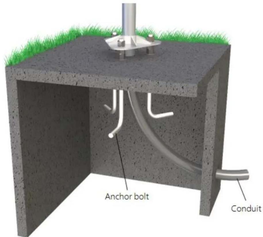
FIGURE 6-2. Cut-away view shows anchor bolt and conduit placement in cement pad
- Use a trowel and edger to finish.
- Wait 24 hours before removing the concrete form.
- Wait seven days before mounting the pole.
6.2 Pole installation
The following components included with the WS-PRO2 are used for this installation procedure:
(1) top pole section (tapered)
(1) base pole section
(6) 5/8-inch washers
(1) 4 m (12 ft), 10 AWG green copper stranded wire
(1) white pole cap
(1) 6 m (20 ft) communications cable (phone or short haul modem)
(1) 6 m (20 ft) power cable (for AC option only)
(1) 6 x 19 mm (1/4 x 3/4 in) hex head self-drilling screw
The pole provides a support structure for mounting the WS-PRO2 weather station components. The pole is designed to withstand winds of 45 m/s (100 mph). The lightning rod assembly is attached after the instrumentation enclosure is installed.
Use the following procedure to attach the pole to the base (FIGURE 6-3 (p. 15)).
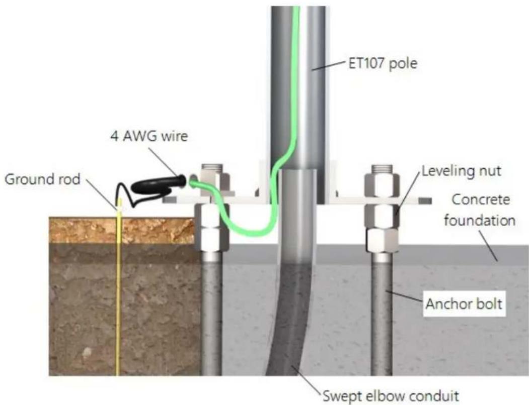
FIGURE 6-3. Transparent view shows raising and grounding the WS-PRO2 pole
- Dig a hole close to the concrete base to access the lower conduit opening.
- From the hole, trench to the power and communications sources.
- Remove the duct tape from both ends of the conduit.
-
Remove the template.
-
Follow the ET Station Pole Assembly Instructions (https://s.campbellsci.com/documents/us/manuals/et-station-pole-assembly-guide.pdf) to secure the top and base pole sections by using the self-drilling screw provided with the pole assembly.
-
Cut and save a 23 cm (9 in) piece of 10 AWG ground wire, which will be used to attach the enclosure ground to the lightning rod assembly.
-
Thread the communications cable, power cable with connector ends of cable out the top of pole, and grounding wire through the pole and conduit. Electrical fish tape will help. Leave approximately 1 m (2 ft) of the supplied power and communications cable hanging out of the top of the pole. Secure all wiring so it doesn't slip back down through the pole.
NOTE:
Solar panel and radio frequency (RF) options will not have power or communications cables.
-
Place the white pole cap over the pole end.
-
Raise the pole on a still day.
-
Place a washer on top of the two nuts on each foundation bolt.
-
Taking care not to damage cables between the pole and conduit, raise the pole and lower it onto the conduit and mounting bolts.
-
Install a washer and nut on each bolt and hand tighten. Check plumb of the pole by placing a level on the north and east sides of the lower pole section.
-
Adjust the topmost of the two lower nuts (leveling nut) on each bolt as necessary.
-
When plumb is established, lock the leveling nut in place by tightening the lowest nut against it.
-
Tighten the three top nuts with the wrench.
6.2.1 Pole grounding
The following components included with the WS-PRO2 are used for this installation procedure:
(1) 4 AWG ground wire
(1) 8 AWG ground wire
(1) copper ground lug, bolt
(1) ground rod, clamp
Use the following procedure to ground the pole (FIGURE 6-3 (p. 15) and FIGURE 6-4 (p. 17)).
- Place the ground rod clamp on the ground rod. Secure it about 8 cm (3 in) from the top. Do this before the rod is driven into the ground. Be careful not to damage the clamp with the hammer.
- Taking care not to damage power or communications lines, drive the ground rod close to the foundation using a fence post driver or sledge hammer. Drive the rod at an angle if an impenetrable hardpan layer exists. Soften hard clay soils with water if necessary.
- Strip 3 cm (1 in) of insulation from both ends of the 4 AWG ground cable.
- Strip 3 cm (1 in) of insulation from the lower end of the 10AWG ground wire.
- Loosen the set screw on the lug and insert the 4 AWG and 10 AWG wire.
- Tighten the set screw (FIGURE 6-4 (p. 17)).
- Loosen the ground rod clamp. Insert the 4 AWG wire. Tighten the clamp (FIGURE 6-4 (p.17)).
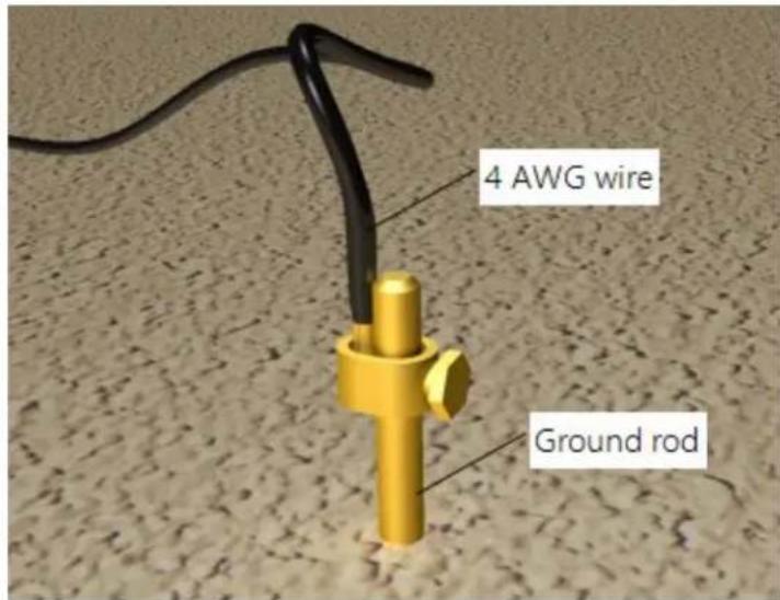
FIGURE 6-4. Close-up of ground rod and 4 AWG cable
6.3 Enclosure installation
The weather station data logger, power supply, sensor connection panel, communications devices, and data retrieval peripherals are mounted in the WS-PRO2 enclosure.
Mount the enclosure on the pole as shown in FIGURE 6-5 (p. 18).
- Remove the front lid.
- Remove the connector cover from the back of the enclosure by loosening the Phillips screw at the bottom of the cover.
- Loosen the mounting bracket bolts on the back of the enclosure wide enough to slide over the pole. Slide the enclosure over the pole.
- Position the enclosure so it faces east for northern latitudes or west for southern latitudes. The top of the enclosure should be 2 to 2.5 ~cm (3/4 to 1 in) above the top of the pole (FIGURE 6-5 (p. 18)).
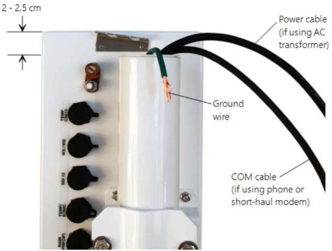
FIGURE 6-5. Enclosure spacing above pole
6.4 AC power installation procedure
The AC power option includes a 100 to 240 VAC to 24 VDC power supply.
- Mount the power supply inside a user-supplied junction box according to local electrical codes.
CAUTION:
Avoid dangerous electrical accidents when using the AC power option by locating the transformer remotely and burying a low voltage line to the station. The low voltage will carry up to 152 m (500 ft) on an 18 AWG power cable.
- Shut off 110 VAC power at the main breaker.
- Connect the primary leads of the power supply to the 100 to 240 VAC power source.
- Connect a two-conductor cable to the secondary terminals of the power supply.
- Route the cable from the power supply to the WS-PRO2 enclosure according to local electrical codes.
- Splice the incoming two-conductor cable to the power cable provided with the station. Use the direct burial splice kit when splices are in a valve box or buried.
CAUTION:
The splice and wire nut must be completely immersed into the silicone gel inside the splice tube to be waterproof.
- Connect the power plug to the POWER connector on the back of the enclosure (FIGURE 6-6 (p. 20)). Ensure that the plug is completely seated on the connector and the locking ring is turned a quarter revolution clockwise.
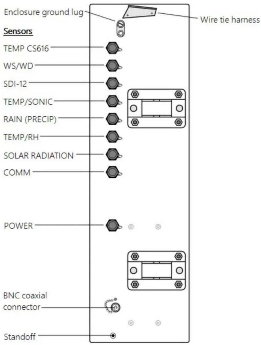
FIGURE 6-6. Position of bulkhead connectors
6.5 Crossarm installation procedure
The crossarm needs to be installed after the enclosure is mounted on the pole. You may need to temporarily remove the communications option. Mount the crossarm as shown in FIGURE 6-7 (p.21) without the wind sensor attached.
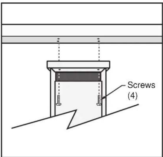
FIGURE 6-7. WS-PRO2 crossarm mounting
- Adjust the bolts at the base of the pole to vertically level the top section of the mounting pole.
- Remove the front lid and the protective connector cover from the back of the enclosure by loosening the one Phillips screw at the bottom of the cover.
- Place the crossarm on top of the enclosure, lining up the four threaded holes on the underside of the arm with the four holes in the top of the enclosure.
- Attach the arm to the enclosure by inserting and tightening four Phillips head screws (FIGURE 6-7 (p. 21)).
- Adjust the position of the enclosure so that the crossarm is oriented along a due north to due south axis with the rain gauge and solar radiation sensor (pyranometer) on the south side for northern latitudes and the reverse for southern latitudes.
6.6 Sensor installation
The following components included with the WS-PRO2 are used for this installation procedure:
(1) WS-PRO2 crossarm with sensors (FIGURE 6-8 (p. 22))
(1) Met One 034B or WindSonic wind sensor
(1) White mounting shaft for 034B or WindSonic
(1) Radiation shield
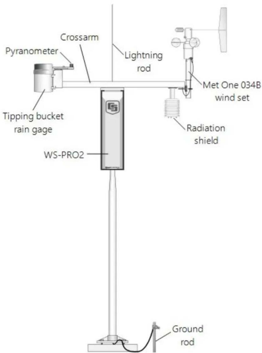
FIGURE 6-8. WS-PRO2 instrumentation mounted on the WS-PRO2 pole
6.6.1 RH and temperature radiation shield installation procedure
- Remove the two knurled thumb screws taped underneath the crossarm.
- Remove the yellow shipping cap from the end of the temperature/relative humidity sensor (FIGURE 6-9 (p. 23) and FIGURE 6-10 (p. 23)).
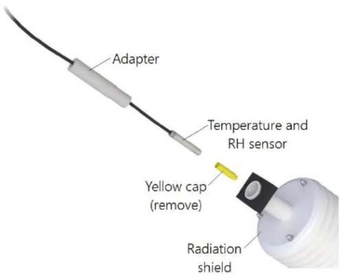
FIGURE 6-9. Temperature/relative humidity sensor with yellow protective cap
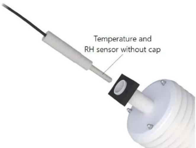
FIGURE 6-10. Temperature/relative humidity sensor without yellow protective cap
- Insert the temperature/relative humidity into the radiation shield until it stops.
- Attach the radiation shield to the underside of the crossarm using the two knurled thumb screws from step 1.
- Plug cable into the TEMP/RH connector on the enclosure. Ensure that the plug is completely seated on the connector and the locking ring is turned a quarter revolution clockwise.
6.6.2 034B Wind Sensor (wind sensor option -MW)
Do the following to install the 034B Wind Sensor after the crossarm is securely installed (FIGURE 6-11 (p. 24)).
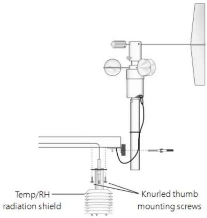
FIGURE 6-11. Wind and RH/temperature sensor installation
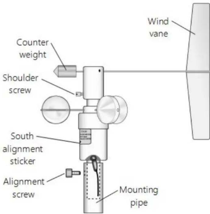
FIGURE 6-12. 034B mounting to pipe
WARNING:
The wind vane can be easily damaged if dropped or bent. Leave the 034B wind vane in the protective cardboard sleeve until it's ready to be installed.
- Remove the alignment screw at the base of the 034B-ET (FIGURE 6-12 (p. 25)).
- Insert the 034B into the 034B Mounting Shaft.
- Align the hole in the shaft with that in the 034B base and replace the screw. Do not overtighten the alignment screw. Do not remove the shoulder screw at this time.
- Insert the mounting shaft through the U-bolt on the crossarm.
- Adjust the mounting shaft so that the cable and connector coming out the end of the crossarm can plug easily into the mating connector on the 034B.
- Lightly tighten up the U-bolt clamp nuts (FIGURE 6-11 (p. 24)).
- Align the arrow on the alignment sticker with True South (Determining True North and wind sensor orientation (p. 87)). The counterweight should also point due south.
-
Make sure the sensor cable is not being pinched by the U-bolt and tighten the U-bolt to hold the sensor firmly.
-
Plug the cable into the mating connector on the sensor. Ensure that the plug is completely seated on the connector and the locking ring is turned a quarter revolution clockwise.
- Install the wind vane using the Allen wrench supplied with the vane. Wind vane should be perpendicular to the crossarm.
- Put the MetOne sticker over the wind vane Allen screw opening.
- Remove and keep the shoulder screw. The shoulder screw will be needed for replacing bearings and/or potentiometer. The wind vane and cups should turn freely.
- Plug the cable into the WS/WD connector on the enclosure. Ensure that the plug is completely seated on the connector and the locking ring is turned a quarter revolution clockwise.
WARNING:
Plugging this sensor into the SDI-12 connector can damage this sensor, the main enclosure connector board, or both.
6.6.3 WindSonic 2-D Ultrasonic Wind Sensor (wind sensor option -GW)
When the WindSonic1-ET is added to the WS-PRO2, a jumper setting must be changed (Changing the jumper (p. 26)).
NOTE:
Jumper is set at the factory if the WindSonic is ordered with the WS-PRO2 station.
6.6.3.1 Changing the jumper
The procedure to change the jumper follows:
- Remove the cover of the enclosure.
- Disconnect the ribbon cable from the CS I/O port.
- Use a Philips screwdriver to loosen the four screws (FIGURE 6-13 (p. 27)).
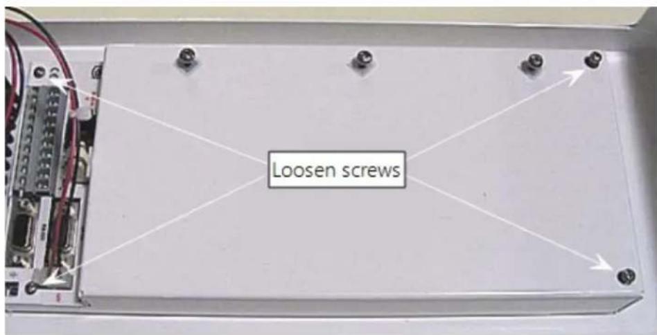
FIGURE 6-13. Screws that secure the electronics cover
- Remove the electronics cover to expose the printed circuit board (PCB) (FIGURE 6-14 (p.27)).
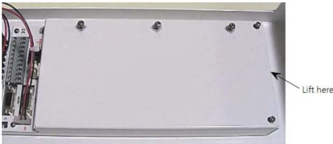
FIGURE 6-14. Removal of the electronics cover
- Move the jumper at the top of the PCB so that it is placed over the center and right pins (FIGURE 6-15 (p. 28)).
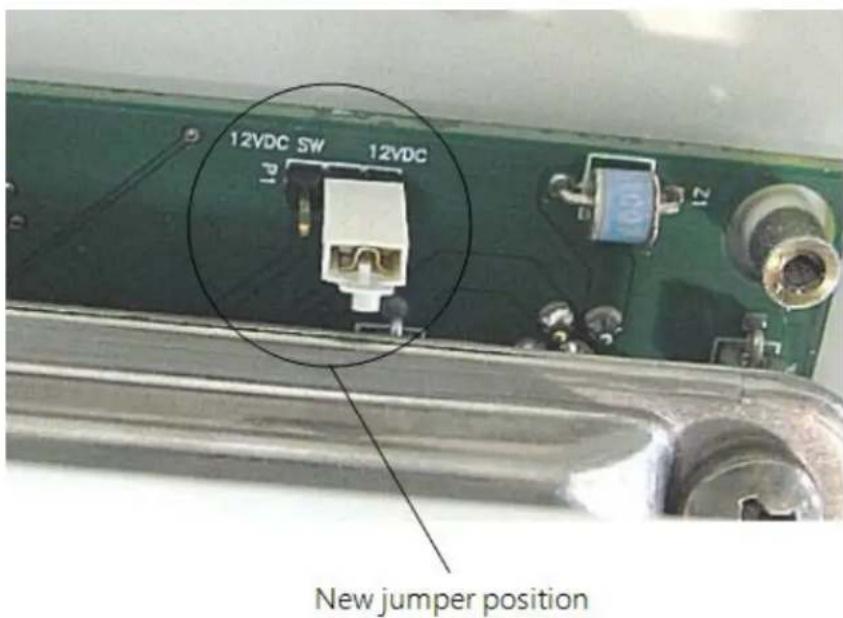
FIGURE 6-15. Jumper set for WindSonic1
- Replace electronics cover.
- Tighten screws.
- Reattach the ribbon cable to the CS I/O port.
- Replace enclosure cover.
6.6.3.2 WindSonic attachment to crossarm
- Remove the three Phillips screws from the end of the white mounting shaft.
- Remove the protective cap covering the WindSonic sensor cable plug.
- Loosen the U-bolt holding the mounting shaft to the crossarm. Pull the shaft up and out of the U-bolt (FIGURE 6-16 (p. 29)).
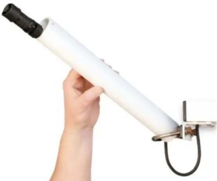
natural_image
Hand holding a white cylindrical object with black connectors, mounted on a metal clamp (no text or symbols visible)FIGURE 6-16. WindSonic mounting shaft
- Slide the connector and cable up through the center of the mounting shaft.
- Plug the cable into the sensor. The connector has a key and needs to be pushed in then rotated clockwise to lock it in place (FIGURE 6-17 (p. 30)).
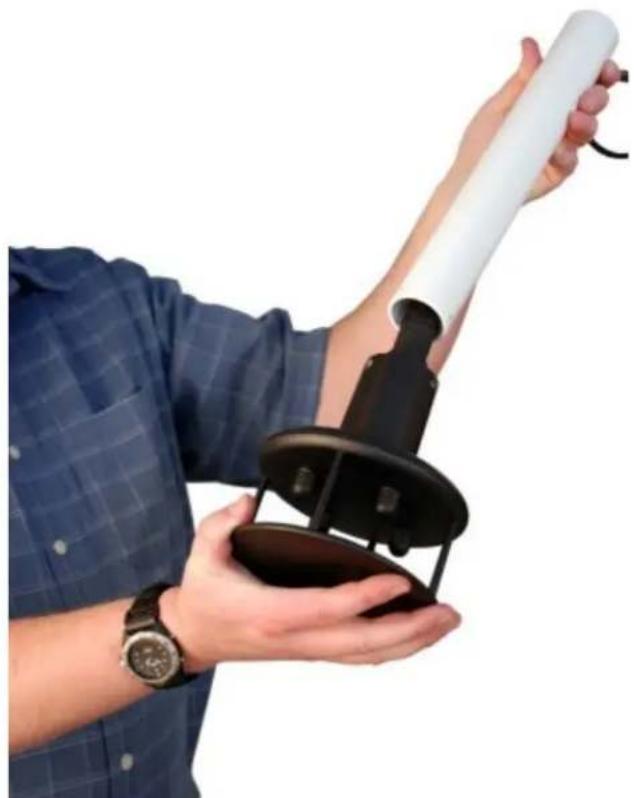
natural_image
Person holding a handheld device with a white cylindrical tube, no visible text or symbolsFIGURE 6-17. WindSonic connected to cable
- Center the WindSonic over the three threaded screw holes on the mounting shaft and screw it in place using the three Phillips screws taken off the shaft in step 1.
- Slide the shaft and sensor back through the U-bolt.
- Align the sensor with north by pointing the small colored dot on outer edge of the bottom of the sensor so it faces true north (Determining True North and wind sensor orientation (p. 87)).
- Space the sensor about 25 cm (10 in) above the crossarm and tighten down the U-bolt.
- Plug the cable into the Temp/Sonic connector on the enclosure. Ensure that the plug is completely seated on the connector and the locking ring is turned a quarter revolution clockwise.
6.6.4 Rain gauge
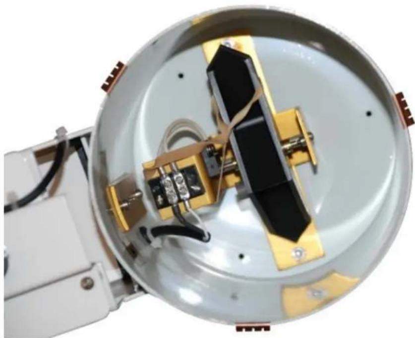
For accurate measurements, the rain gauge needs to be installed so it is horizontally level. A bubble level on the bottom of the inside of the rain gauge shows how vertical the pole was installed.
-
Pull the gold funnel up and off of the top of the rain gauge.
-
Remove the rubber band holding the tipping mechanism in place (FIGURE 6-18 (p. 31)).
natural_image
Interior view of a spacecraft or satellite module with visible structural components and wiring (no text or symbols)FIGURE 6-18. Remove rubber band from tipping mechanism
-
Adjust the bolts at the bottom of the pole as needed to get the bubble level centered.
-
Put the gold funnel back on the top of the rain gauge after leveling has been completed.
-
Plug the cable in the RAIN/PRECIP connector on the enclosure. Ensure that the plug is completely seated on the connector and the locking ring is turned a quarter revolution clockwise.
6.6.5 Pyranometer
- Adjust the three leveling screws until the bubble level indicates plumb (FIGURE 6-19 (p. 32)).
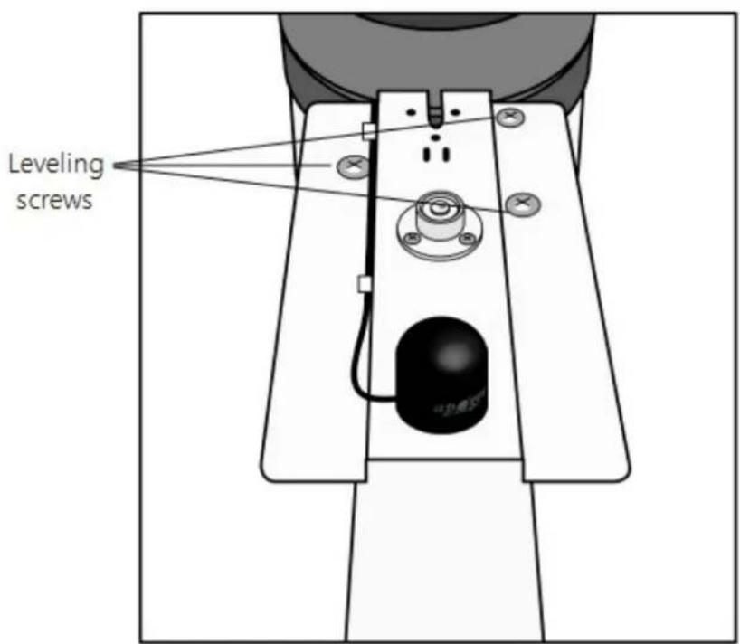
FIGURE 6-19. Pyranometer leveling
- Remove the red or green shipping cap from the pyranometer (FIGURE 6-20 (p. 32)).
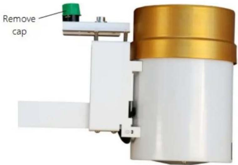
FIGURE 6-20. Remove red or green pyranometer cap
- Plug the cable in the SOLAR RADIATION connector on the enclosure. Ensure that the plug is completely seated on the connector and the locking ring is turned a quarter revolution clockwise.
6.6.6 107 or 108 soil temperature sensor (optional)
The 107 and 108 temperature sensors have a -C Cable Termination option that allows them to connect to the WS-PRO2. With this option, the cable terminates in a connector that attaches to the WS-PRO2. This is equivalent to the -LC version available for some sensors.
NOTE:
Rain Bird recommends routing the cable of the optional soil sensors in conduit, especially if the soil is rocky or rodents are present. The cables for these sensors do NOT have an armored outer jacket. The jacket is waterproof but NOT cut proof.
- Bury the conduit from the weather station to the soil temperature site.
- Route the sensor cable through the conduit.
- Bury the end of the sensor so it is in contact with the soil surface to be measured. See sensor manual for complete instructions.
- Plug this sensor into one of three possible connectors on the WS-PRO2 enclosure. Check the programming software for correct station connection. Ensure that the plug is completely seated on the connector and the locking ring is turned a quarter revolution clockwise.
6.6.7 Sensor connections
Each sensor cable plug attaches to a unique bulkhead connector (FIGURE 6-6 (p. 20) and FIGURE 6-21 (p. 34)). The labeling of the sensor cables match the labeling on the back of the enclosure. For more information, refer to Sensor schematics (p. 73).
CAUTION:
Each plug must be completely seated on to the connector and the locking ring turned a quarter revolution clockwise. Failure to seat the plug completely could cause corrosion and water damage to both the enclosure and the cable.
NOTE:
Notice how the sensor caps are slid between the connector and the one above in FIGURE 6-21 (p. 34). This will keep the caps out of the way of the connector cover.
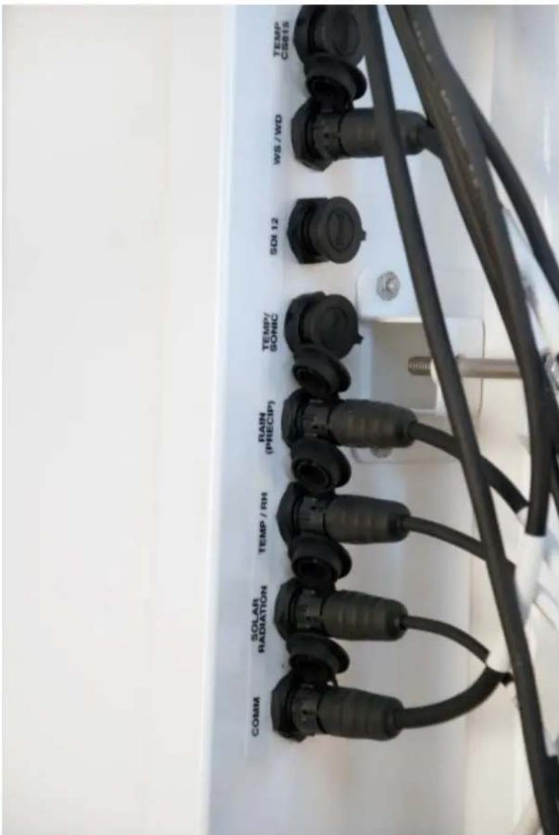
FIGURE 6-21. Connecting sensor cabling to enclosure
6.6.8 Sensor verification and clock set
- Contact Rain Bird if needed to assist with SmartWeather software setting changes necessary to activate soil temperature.
a. The station can be accessed directly using a CR1000KD keypad display at the weather station. Plug the keypad into the extra plug coming off the 9-pin CS I/O connector.
b. A laptop can be used to connect directly to the RS-232 port at the station using a standard 9-pin serial cable. Do NOT use a null modem cable.
- Verify all sensors are functioning correctly.
- Verify the weather station clock and set as necessary.
NOTE:
Use standard time in the station if calculating. Do not use daylight savings time.
6.7 Communications peripherals
Communications kits ordered with the enclosure are pre-mounted and pre-wired; no further connections inside the enclosure are necessary. Follow the external installation procedures in later sections to make the external connections.
If you received a telecommunications kit separate from the enclosure, follow the "Internal Installation" procedures outlined in later sections. Schematics for the phone and short haul modems are in Communications modems schematics (p. 78).
Default settings for the data logger in the WS-PRO2 station:
- PakBus address 1
• RS-232 Port: Autobaud (300 to 115,200 bps)
• ME: Autobaud
• SDC7 or SDC8: 115,200 bps
6.7.1 Direct connect to WS-PRO2 station
The WS-PRO2 station does not require an interface device for direct RS-232 communications. The inside of the enclosure has a RS-232 and CS I/O port available for communications (see FIGURE 6-22 (p. 36)). Most standard communications options use the CS I/O port leaving the RS-232 port free for direct communications with a laptop or desktop computer using a standard RS-232 serial cable. The data logger used in the WS-PRO2 station can communicate with more than one device at a time allowing troubleshooting to be done in the field with a laptop computer while remote communications devices are accessing the station.
NOTE:
Use Device Configuration Utility and connect directly to the station to change the data logger configuration. Device Configuration Utility can be obtained, at no charge, from
www.campbellsci.com/downloads
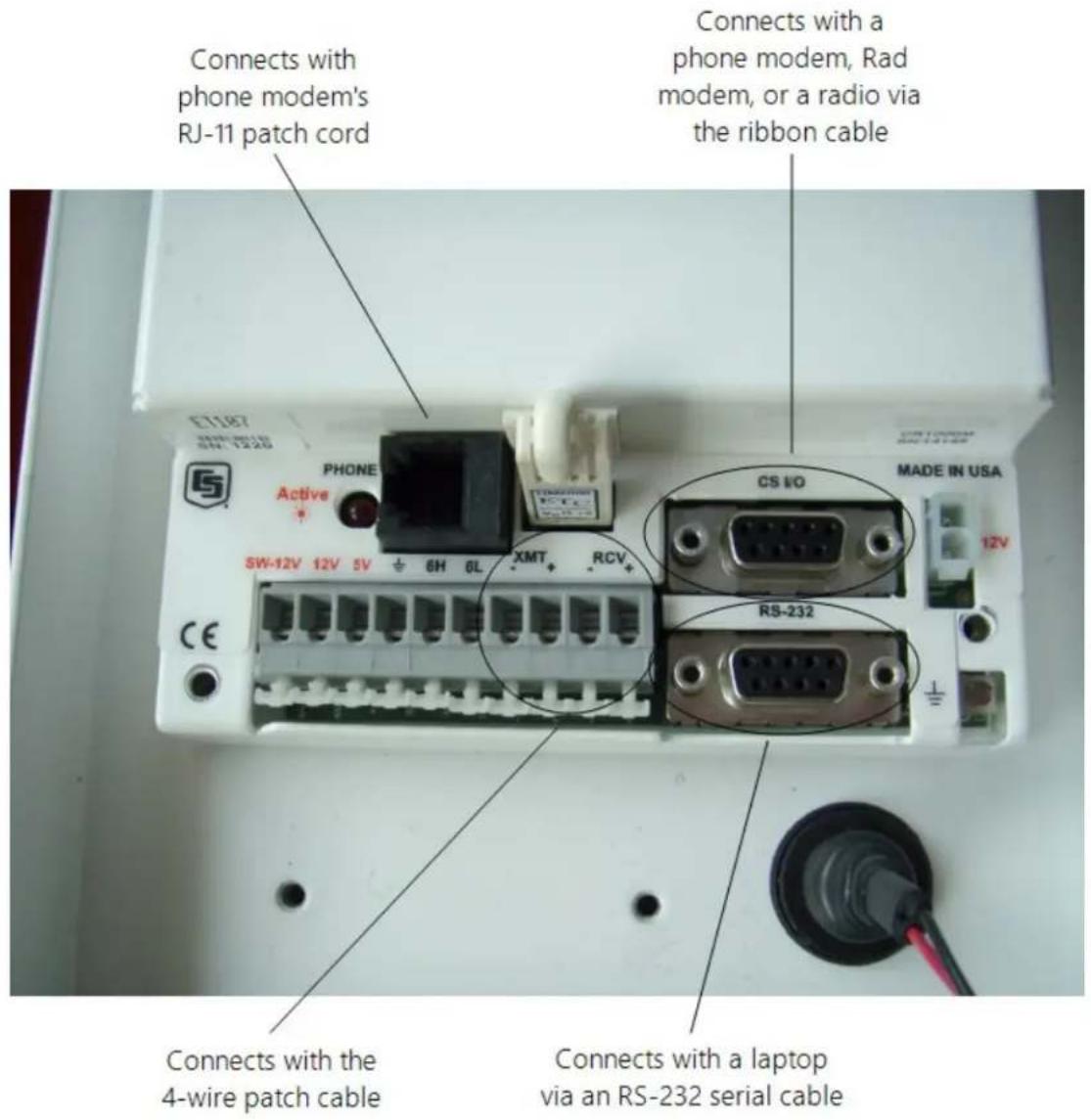
FIGURE 6-22. Close-up of the terminals and 9-pin ports in the WS-PRO2 (battery not shown)
6.7.2 Phone modem
Phone modems enable communications between the WS-PRO2 enclosure and a Hayes compatible modem at your computer over a dedicated phone line. Phone line surge protection is built into the enclosure. By default, the COM220 phone modem is configured for SDC7.
6.7.2.1 Internal installation of phone modem
NOTE:
If the phone modem was ordered with the WS-PRO2, skip this section and go directly to External installation of phone modem (p. 38).
For installation inside the WS-PRO2 enclosure, the following components are provided in the phone modem kit:
(1) COM220 phone modem
(1) 30 cm (12 in) RJ-11 patch cord
(1) Mounting bracket
(4) Screws
(1) 130 cm (12 in) 14 AWG ground wire
Use the following procedure to install the phone modem (FIGURE 6-23 (p. 37)).
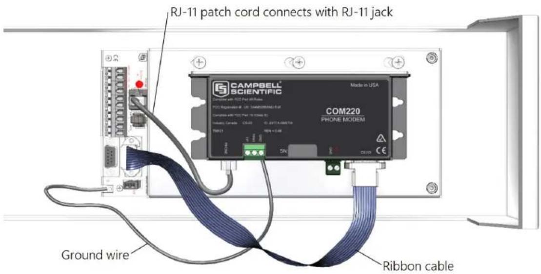
FIGURE 6-23. Phone modem mounting and connections (battery not shown)
- Attach the modem to the modem bracket with the two screws provided. Mount the modem and bracket into the enclosure with the three screws on the mounting plate.
-
Connect the modem 9-pin port to the enclosure CS I/O port with the ribbon cable supplied with the enclosure (FIGURE 6-22 (p. 36), FIGURE 6-23 (p. 37)).
-
Connect the modem RJ-11 jack to the enclosure RJ-11 jack with the RJ-11 patch cord (FIGURE 6-23 (p. 37)).
- Connect the modem ground terminal block (GND) to the enclosure ground by using the 14 AWG ground wire.
6.7.2.2 External installation of phone modem
The following modem kit components are used to make the external connections:
(1) Direct Burial Splice Kit
(1) 6 m (20 ft) Telephone Patch Cord with Connector
1. Connect the 6 m (20 ft) patch cord to the COM connector on the external back panel, under the protective cover. Ensure that the plug is completely seated.
2. Splice the Tip and Ring lines of the patch cord to the telephone service line. Use the direct burial splice kit when splices are in a valve box or buried.
NOTE:
The splice and wire nut must be completely immersed into the silicone gel inside the splice tube to be waterproof.
6.7.3 Short-haul modem
Short-haul modems enable communications between a data logger and computer over two twisted pairs of wires. The maximum distance between modems is determined by baud rate and wire gauge. At 9600 bps, the approximate maximum cable length is 10 km (6 miles) using 19 AWG cable. DCE / DTE switches on the modems are set to DCE.
CAUTION:
It's critical to use at least a two twisted-pair cable with a shield wire. Shield wire(s) and/or any additional unused conductors must connect to an earth ground at one end or the other of the cable run.
6.7.3.1 Internal installation of short haul modem
NOTE:
If the short haul modem was ordered with the WS-PRO2, skip this section and go directly to External installation of short haul modem (p. 40).
For installing inside the WS-PRO2 enclosure, the following components are provided in the short-haul modem kit:
(1) SC932C 9-pin to RS-232 DCE interface
(1) RAD modem
(1) RAD/SC932C mounting bracket
(1) 130 cm (12 in) 4-wire patch cable
Use the following procedure to install the short-haul modems (FIGURE 6-24 (p. 39) and FIGURE 6-25 (p. 40)).
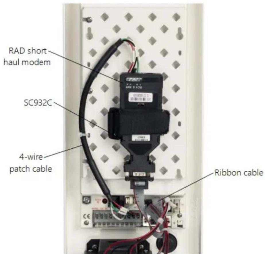
FIGURE 6-24. Short-haul modem mounting and connection (battery not shown)
- Mount the RAD / SC932C mounting bracket into the enclosure with the three screws provided.
- Connect the RAD modem and SC932C.
-
Strap them into the mounting bracket under the Velcro strap.
-
Connect the SC932C 9-pin port to the internal enclosure CS I/O port with the ribbon cable supplied with the enclosure (FIGURE 6-24 (p. 39)).
- Wire the RAD modem to the enclosure with the 30 cm (12 in) patch cable. Match wire labels to wiring panel labels on both the enclosure and the RAD modem (+XMT to +XMT). A small screwdriver is provided with the enclosure to access the RAD modem connections. Use the screwdriver to press down on the lever arm.
WARNING:
Pressing too hard on the lever arm can break it!
6.7.3.2 External installation of short haul modem
flowchart
graph TD
    A["PC"] --> B["SRM-5A"]
    B --> C["Surge Protector"]
    C --> D["Earth Ground"]
    D --> E["User Supplied Cable"]
    E --> F["Splices"]
    F --> G["To # 8 External Connector"]
    H["ET107 Enclosure"] --> I["- RCV (white)"]
    H --> J["+ RCV (green)"]
    H --> K["- XMT (black)"]
    H --> L["+ XMT (red)"]
    H --> M["+ RCV (red)"]
    H --> N["- RCV (black)"]
    H --> O["+ XMT (green)"]
    H --> P["- XMT (white)"]
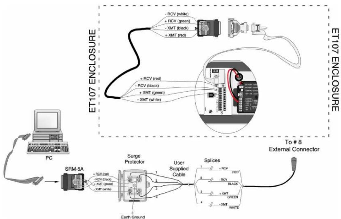
FIGURE 6-25. Short-haul modem wiring diagram
Components of the short haul kit used for external connections at the WS-PRO2 enclosure are:
(1) 6 m (20 ft) 4-wire patch cable
(2) Direct burial splice kits
(1) User-supplied 22 AWG, REA, PE-86 Filled Buried Wire (supplier: Anixter,
www.anixter.com/en_us.html, Anixter pn F-02P22BPN)
Components of the short haul kit used for external connections at the computer are:
(1) RAD modem
(1) 1.5 m (5 ft) 4-wire patch cable
(1) 3 m (10 ft) 14 AWG ground wire
(1) Surge protector and case
(1) 9-25 pin RS-232 serial cable
Use the following procedure to install the short haul modems (FIGURE 6-25 (p. 40)).
- Connect the 6 m (20 ft) patch cable to the COM connector on the back side of the enclosure. Splice the patch cable to the user-supplied cable, using the direct burial splice kits.
NOTE:
The splice and wire nut must be completely immersed into the silicone gel inside the splice tube to be waterproof.
- Mount the surge protector box to a flat surface within 1.5 m (5 ft) of the serial port on the computer. Ground the center terminal to an earth (or building) ground using the 14 AWG wire.
- Connect the 1.5 m (5 ft) patch cable from the surge box to the RAD Modem. Fasten the cable to the strain relief tab with a cable tie. Use the 9-to-25 pin serial cable to connect the modem to the serial port on the computer.
- Route the user-supplied cable from the remote splice to the surge protector. Connect it and the 1.5 m (5 ft) patch cable to the surge protector.
6.7.4 Radio
Radios enable wireless communications between a data logger and computer. Maximum range is 0.8 to 21 km (0.5 to 13 miles). This is determined by radio model, antennas used, line of site, and interference. Radio communications using the SmartWeather alarm systems require an SC932A RS-232 DCE Interface and a field power cable. The SC932A is connected between the radio RS-232 port and the WS-PRO2 CS I/O port. For the field power cable, the barrel plug connects to the radio and the two-conductor pigtail connects to the 12V and G terminals of the WS-PRO2. This section provides instructions for RF407, RF412, RF422, RF451 and most radios offered by Campbell Scientific.
NOTE:
AC power is recommended when using radios with the station. A 10-watt solar panel can be used but days without sunlight and winter months with little sunlight should be considered. The WS-PRO2 station comes with a 7 amp-hour battery that is NOT designed to handle deep discharge. Discharging the battery below 11 VDC may require battery replacement. Below are some examples of power calculations. Battery current consumption is based on discharging the 7 amp-hour battery to 80% capacity (5.6 amp-hours). Discharging the battery past this value could result in damaging the battery.
6.7.4.1 Example radio configuration and power usage
Configuration of base radio at the computer:
- Multi-Point Master
• RS-232 @ 9600 bps
• Network ID: 1234 - Frequency Key: 5
• 1 Watt Output (Transmit Power: 10)
Weather station radio:
- Multi-Point Slave
• Communication with Data logger via CS I/O SDC7
• Network ID: 1234 - Frequency Key: 5
• 1 Watt Output (Transmit Power: 10) - Low Power Mode: 2
See your spread spectrum radio manual for changing radio settings.
Power usage example:
Polling the station once an hour and staying on line with the station for one minute consumes approximately 0.388 amps over a 24-hour period. If the station were to lose power, it could run for around 14 days (346 hours) before damaging the battery. A station with a 10-watt panel would need at least one hour of sunlight every day to keep the battery charged.
6.7.4.2 Internal installation of the radio
NOTE:
If the WS-PRO2 was ordered with a radio kit, skip this section and go directly to External installation of the radio (p. 44).
The following components are provided in the radio kit for installation inside the WS-PRO2 enclosure:
(1) spread spectrum radio
(1) internal antenna cable
(1) enclosure mounting bracket
The radio comes mounted to the enclosure bracket. Install the assembly as follows.
NOTE:
Power the station down by moving the PS150 power switch to the Off position before installing any communications option. Remember to move the switch back to the On position after installing the enclosure.
- Mount the bracket and radio inside the enclosure using the three existing screws (FIGURE 6-26 (p. 43)).
- Thread the smaller SMA connector end of the internal antenna cable underneath the battery cables and screw it to the RF antenna connector on the radio.
- Attach the other end of the cable to the BNC RF bulkhead connector in the lower right corner of the enclosure. Make sure all connections are tight (FIGURE 6-26 (p. 43)).
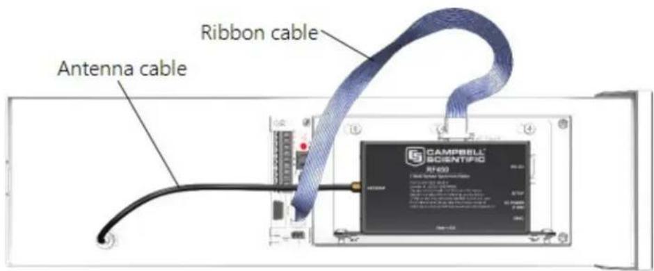
FIGURE 6-26. Radio mounted in the WS-PRO2 (battery not shown)
- Connect the long 9-pin female end of the ribbon cable to the CS I/O port on the radio.
- Screw the connector to the radio using the provided two screws (FIGURE 6-27 (p. 44)).
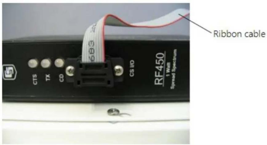
FIGURE 6-27. Attach ribbon cable to radio CS I/O port
6.7.4.3 External installation of the radio
The antenna should have been ordered with the radio kit.
The following components are provided with the radio kit for antenna installation on the WS-PRO2 pole:
(1) antenna cable, 150 cm (59 in)
(1) adjustable angle antenna mounting bracket
(1) 8-450 x 53 mm (5/16-18 x 2 1/4 in) stainless steel U-bolt
(1) CM230 saddle bracket
(4) silicon bronze 8-450 mm (5/16-18 in) nuts
(4) 8 mm (5/16 in) stainless steel washers
(4) 8 mm (5/16 in) stainless steel lock washers
(4) black UV-resistant wire ties
- Remove the sensor cable cover off of the back of the enclosure by loosening the thumb screw at the bottom of the cover and swinging the cover back and down. The top of the cover has a tab that fits in to the rectangular hole on the back of the sensor crossarm.
- Remove the cap off of the BNC bulkhead connector located on the lower left corner of the enclosure back.
- Attach the antenna cable to the BNC connector.
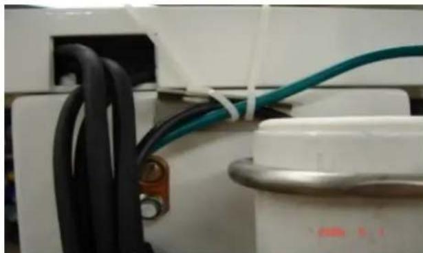
- Gently bring the cable up alongside the pole and loosely wire tie it to the wire tie block at the top of the enclosure (FIGURE 6-28 (p. 45)).
natural_image
Close-up of electrical wiring with black and teal wires attached to a white appliance (no visible text or symbols)FIGURE 6-28. Loosely wire tie antenna cable
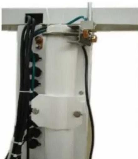
- Drape the antenna cable between the pole and the enclosure (FIGURE 6-29 (p. 45)).
natural_image
Close-up of a white cylindrical device with black wires and connectors, mounted on a metal frame (no visible text or symbols)FIGURE 6-29. Loosely drape antenna cable over back of enclosure
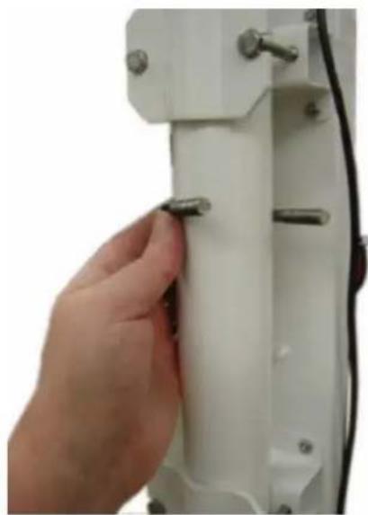
- Use the 2.125 stainless steel U-bolt to attach the adjustable angle mounting bracket to the pole. Depending on the size of the antenna, position the bracket directly below, or above, the enclosure top mounting bracket. The top of an omnidirectional antenna should not be higher than the top of the lightning rod.
a. Slide the U-bolt behind the pole and through the oval notches on the adjustable angle mounting bracket (FIGURE 6-30 (p. 46)).
natural_image
Close-up of a hand adjusting a white mechanical component with metal pins (no visible text or symbols)FIGURE 6-30. Slide antenna bracket U-bolt around back of the pole
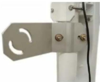
b. Put a flat washer, lock washer, and a silicon bronze nut, in that order, on the ends of the U-bolt (FIGURE 6-31 (p. 46)).
c. Tighten the nuts finger tight to allow the angle bracket to rotate around the pole.
natural_image
Close-up of a metallic mechanical component with a curved cutout and two connectors (no visible text or symbols)FIGURE 6-31. Antenna bracket mounted to pole
-
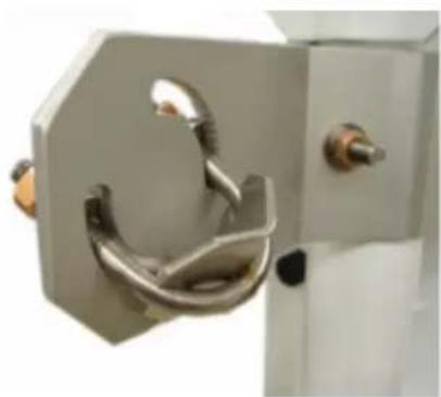
Mount the saddle bracket to the adjustable angle mount bracket by inserting the ends of the bracket through the quarter circle notches (FIGURE 6-32 (p. 47)).
-
Put a flat washer, lock washer, and a silicon bronze nut, in that order, on the ends of the saddle bracket. Do NOT tighten down the nuts at this time.
natural_image
Close-up of a metallic mechanical component with a loop handle and two bolts (no visible text or symbols)FIGURE 6-32. Mount antenna saddle bracket
NOTE:
Only rotate enclosure if needed to allow aiming of the Yagi antenna to the base antenna. Keep solar radiation sensor towards the south as much as possible. Rotate wind sensor to realign as needed.
- Use the following procedure to install the Yagi antenna for the radio. Installation of the omnidirectional antenna is similar (FIGURE 6-35 (p. 49)).
NOTE:
Mounting hardware that comes in the box with the Yagi antenna will not be used.
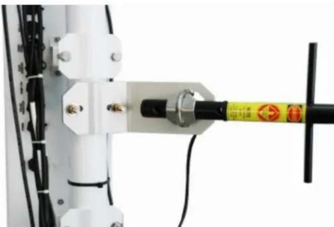
a. Slide the back of the Yagi antenna into the saddle bracket.
b. If the Yagi antenna at the station is communicating with an omnidirectional antenna at the base, align the tines on the Yagi antenna so they are vertical (FIGURE 6-33 (p. 48)). If two Yagi antennas are used at both ends of communications, align the tines the same. If interference is a concern, align the tines on the two Yagi antennas horizontally instead of vertically. This will put the signal out of phase with other antennas that are aligned vertically.
c. Tighten the nuts on saddle bracket to hold the antenna firmly in place.
CAUTION:
Do NOT over tighten the nuts on the saddle bracket or damage to the antenna may occur.
natural_image
Close-up of a mechanical device with a yellow warning tag and black handle, no visible text or symbolsFIGURE 6-33. Yagi antenna mounted to saddle bracket
d. Orient the Yagi antenna so it's aimed at the base antenna. You may have to flip the adjustable angle bracket over to get the antenna and saddle bracket to point correctly in the vertical direction.
e. Adjust the antenna cable at the BNC connector so the cable cover fits over all the sensor cables as well as the antenna cable. You may have to gently bend the antenna cable to put a 90^ bend by the BNC connector end of the cable. Take the cover off when you're done.
f. Use one of the black wire ties to strap the antenna cable to the bundle of sensor cables.
g. Tighten up the wire ties holding the antenna cable to the wire tie mount at the top of the enclosure.
h. Take one black wire tie and strap the antenna cable to the antenna (FIGURE 6-34 (p. 49)). Leave a little slack on the cable between the wire tie and the antenna connector so as not to stress the connector/cable connection.
i. Make sure a loop of antenna cable is directly under the Yagi antenna. This will act as a drip loop and allow moisture to run off the antenna and cable (FIGURE 6-34 (p. 49)).
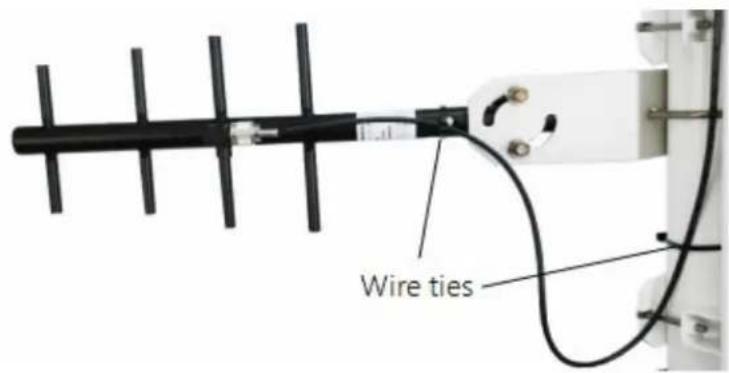
FIGURE 6-34. Wire tie antenna cable to Yagi antenna and to pole
j. Wire tie the antenna cable to the pole.
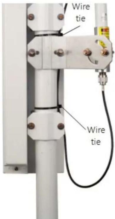
FIGURE 6-35. Wire tie locations for omnidirectional antenna installation
k. Clean up the wire ties and put the cable cover back on.
6.7.4.4 Base radio installation
The base radio kit comes with the following items.
(1) RS-232 serial data cable
(1) wall adapter (100 to 240 VAC, 50 to 60 Hz input; 12 VDC, 800 mA output; 1.8 m (6 ft) cable)
(1) radio
(1) window mount antenna with 2 m (7 ft) of cable
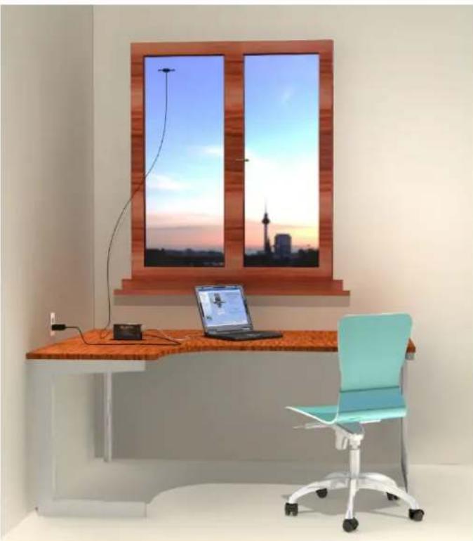
The radio needs to be connected to an RS-232 serial port on the calling computer and powered by the wall adapter. The antenna is designed to stick to a window facing the weather station (FIGURE 6-36 (p. 50) and FIGURE 6-37 (p. 51)).
CAUTION:
To comply with the FCC RF exposure requirements, the radio may be used only with approved antennas that have been tested with this radio and a minimum separation distance of 8 inches (20 cm) must be maintained from the antenna to any nearby persons.
- Attach the RSMA connector on the antenna to the radio.
- Remove the strip covering the adhesive on the antenna and stick it vertically to a window.
- Attach the serial cable from the calling computer's serial port to the RS-232 port on the spread spectrum radio.
- Plug the wall adapter into a wall outlet and plug the barrel connector into the POWER connector. You should see the lights on the radio come on.
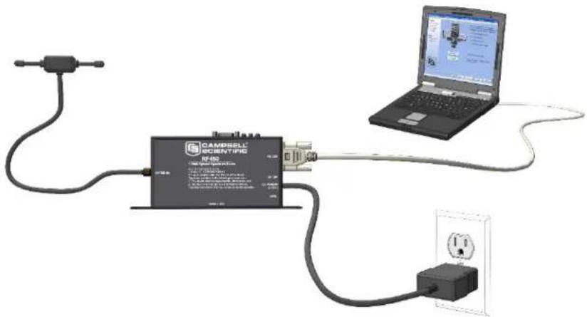
FIGURE 6-36. Base Radio installation
natural_image
Interior scene of a modern office desk with a window, laptop, and chair (no visible text or symbols)FIGURE 6-37. A base radio installed in an office
6.7.5 WS-PRO2 cell phone accessory kit
This kit includes hardware for installing a cellular phone to an WS-PRO2 weather station. The cellular modem and antenna are ordered separately.
6.7.5.1 Cellular modems available from Campbell Scientific
Campbell Scientific currently offers cellular modems that provide serial and Ethernet connectivity to numerous cellular networks. The networking and carrier used by the cell modem are determined by the active SIM card(s) inserted into the device.
NOTE:
Before purchasing a digital cellular modem, ensure that the data logger site has cellular coverage. Campbell Scientific offers low cost, cellular data service plans for the cell modem. Those data service plans include Verizon in the United States and AT&T in North America (US, Mexico, Canada), as well as international access to over 600 carriers in 185 countries.
6.7.5.2 Power considerations
Rain Bird recommends using either AC power or a 10-watt solar panel and the PS24 power supply. Refer to PS24 24 Ah power supply with 10 x 12 inch enclosure (p. 91) for mounting options and information on the PS24.
6.7.5.3 Antenna
Rain Bird recommends the 2 dBd 4G/3G Multiband Omnidirectional Antenna for the cell modem in an WS-PRO2 station. This antenna is ideally suited for use with 4G and 3G cellular gateways.
NOTE:
Mounting hardware that comes in the box with some antennas will not be used. The cell phone kit provides the hardware needed to mount the antenna to the WS-PRO2 pole.
6.7.5.4 Establishing cellular service and configuring the cellular modem
To use a cellular modem, you must first establish cellular service. The modem then needs to be activated and programmed for use with Campbell Scientific equipment. Procedures for doing these tasks are provided in the cellular modem manual.
NOTE:
It is recommended to test the modem in the office (assuming there is cellular coverage) prior to installing it in the field.
6.7.5.5 Internal installation of the cellular modem
NOTE:
If the cellular phone accessory kit and cellular modem were ordered with the WS-PRO2, skip this section and go directly to External installation of a cellular modem (p. 53).
For installation inside the enclosure, the following components are provided in the cell phone accessory kit:
(1) ET Enclosure Universal Communications Mounting Bracket
(1) Antenna Cable for ET Stations, 59 in.
(1) Velcro Strap, 2.5 x 46 cm (1 x 18 in)
(1) 33 cm (13 in) coaxial cable with SMA-to-BNC connectors
(1) ET Antenna Adjustable-Angle Mounting Bracket
(1) Stainless-Steel U-Bolt Screw 5/16-18 x 2.125 with 2 Silicon Bronze Nuts
(1) U-bolt with Saddle Bracket and 2 Nuts
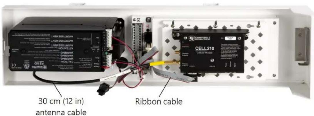
FIGURE 6-38. Cellular modem mounted inside the WS-PRO2 (power supply not shown)
NOTE:
This installation procedure is for installing the CELL210. The RV50 uses a null modem cable instead of a ribbon cable and uses a power cable to connect to the SW12 or 12V terminal on the WS-PRO2.
- Fasten the mounting bracket to the enclosure using the three screws provided.
- Thread the smaller SMA connector end of the internal antenna cable underneath the battery cables and screw it to the RF antenna connector on the cellular modem (FIGURE 6-38 (p. 53)).
- Attach the other end of the cable to the BNC RF bulkhead connector in the lower right corner of the enclosure. Make sure all connections are tight.
- Use the ribbon cable to connect the CS I/O port on the CELL210 to the CS I/O 9-pin port on the WS-PRO2 (FIGURE 6-38 (p. 53)).
- The CELL210 is powered from the CS I/O port.
6.7.5.6 External installation of a cellular modem
The antenna should have been ordered with the kit.
NOTE:
Mounting hardware that comes in the box with the antenna will not be used.
To mount the antenna onto the WS-PRO2 pole, the cell phone accessory kit contains the following hardware, which is the same hardware used in the spread spectrum radio kit:
(1) antenna cable, 150 cm (59 in)
(1) adjustable angle antenna mounting bracket
(1) 8-450 x 53 mm (5/16-18 x 2 1/4 in) stainless steel U-bolt
(1) CM230 saddle bracket
(4) silicon bronze 8-450 mm (5/16-18 in) nuts
(4) 8 mm (5/16 in) stainless steel washers
(4) 8 mm (5/16 in) stainless steel lock washers
(4) black UV-resistant wire ties
- Fasten the mounting hardware onto the WS-PRO2 pole by following steps 1 through 8 in External installation of the radio (p. 44).
- Slide the back of the antenna into the saddle bracket and tighten its nuts to hold the antenna firmly in place.
CAUTION:
Do NOT over tighten the nuts on the saddle bracket or damage to the antenna may occur.
- If using the Yagi antenna, aim the antenna at the cellular pole. You may have to flip the adjustable angle bracket over to get the antenna and saddle bracket to point correctly in the vertical direction.
- Adjust the antenna cable at the BNC connector so the cable cover fits over all the sensor cables and the antenna cable. You may have to gently bend the antenna cable to put a 90° bend by the BNC connector end of the cable. Take the cover off when you're done.
- Use one of the black wire ties to strap the antenna cable to the bundle of sensor cables.
- Tighten up the wire ties holding the antenna cable to the wire tie mount at the top of the enclosure.
- Take one black wire tie and strap the antenna cable to the antenna. Leave a little slack on the cable between the wire tie and the antenna connector so as not to stress the connector/cable connection.
- Wire tie the antenna cable to the pole. Clean up the wire ties and put the cable cover back on.
6.7.6 NL241 Wi-Fi accessory kit
The wireless network link kit includes hardware for installing a Wi-Fi network link into an WS-PRO2 weather station. The Wi-Fi modem accessory kit and antenna are ordered separately.
6.7.6.1 Antenna
Rain Bird recommends the 2.4 GHz 5.8 dBd omnidirectional antenna with the NL241 Wi-Fi modem in an WS-PRO2 station. This antenna provides a 5.8 dBd gain.
The Wi-Fi kit provides the hardware needed to mount the antenna to the WS-PRO2 pole.
6.7.6.2 Power considerations
Rain Bird recommends using either AC power or a 10-watt solar panel and the PS24 power supply. Refer to PS24 24 Ah power supply with 10 x 12 inch enclosure (p. 91) for mounting options and information on the PS24.
6.7.6.3 Internal installation of Wi-Fi modem
If the wireless network link kit was ordered with the WS-PRO2, skip this section and go directly to External installation of the Wi-Fi modem (p. 56).
For installation inside the WS-PRO2 enclosure, the following components are provided in the kit:
(1) Mounting bracket
(1) 36 cm (14 in) Coaxial Cable with RPSMA-to-BNC Connectors
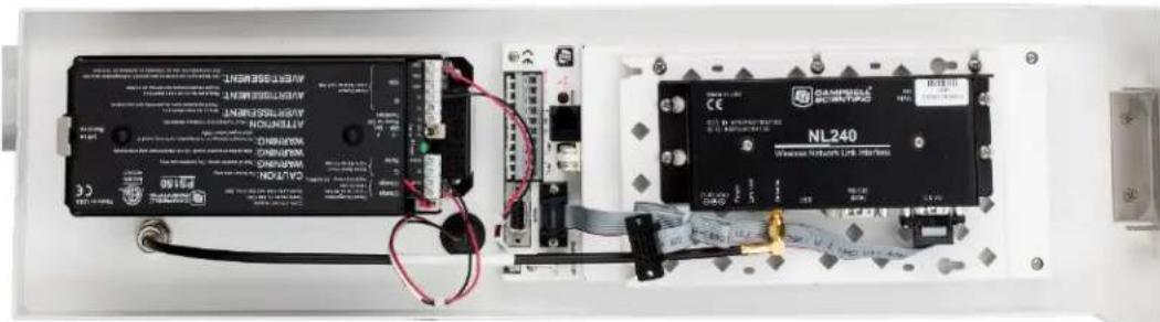
FIGURE 6-39. Wi-Fi modem mounted inside the WS-PRO2
- Fasten the mounting bracket to the enclosure using the three screws provided.
-
Thread the smaller SMA connector end of the internal antenna cable underneath the battery cables and screw it to the RF antenna connector on the NL241 Wi-Fi modem.
-
Attach the other end of the cable to the BNC RF bulkhead connector in the lower right corner of the enclosure. Make sure all connections are tight (FIGURE 6-39 (p. 55)).
- Use the ribbon cable to connect the CS I/O port on the NL241 to the CS I/O 9-pin port on the WS-PRO2 (FIGURE 6-39 (p. 55)).
6.7.6.4 External installation of the Wi-Fi modem
The 2.4 GHz/5.8 dBd Omnidirectional Wi-Fi Antenna should have been ordered with the kit.
To mount the antenna onto the WS-PRO2 pole, the Wi-Fi accessory kit contains the following hardware:
(1) antenna cable, 150 cm (59 in)
(1) adjustable angle antenna mounting bracket
(1) 8-450 x 53 mm (5/16-18 x 2 1/4 in) stainless steel U-bolt
(1) CM230 saddle bracket
(4) silicon bronze 8-450 mm (5/16-18 in) nuts
(4) 8 mm (5/16 in) stainless steel washers
(4) 8 mm (5/16 in) stainless steel lock washers
(4) black UV-resistant wire ties
- Fasten the mounting hardware onto the WS-PRO2 pole by following steps 1 through 8 in External installation of the radio (p. 44).
- Slide the back of the antenna into the saddle bracket and tighten its nuts to hold the antenna firmly in place.
CAUTION:
Do NOT over tighten the nuts on the saddle bracket or damage to the antenna may occur.
- Adjust the antenna cable at the BNC connector so the cable cover fits over all the sensor cables as well as the antenna cable. You may have to gently bend the antenna cable to put a 90° bend by the BNC connector end of the cable. Take the cover off when you're done.
- Use one of the black wire ties to strap the antenna cable to the bundle of sensor cables.
- Tighten the wire ties holding the antenna cable to the wire tie mount at the top of the enclosure.
-
Take one black wire tie and strap the antenna cable to the antenna. Leave some slack on the cable between the wire tie and the antenna connector so as not to stress the connector/cable connection.
-
Wire tie the antenna cable to the pole. Clean up the wire ties and put the cable cover back on.
-
Refer to the NL241 user manual for setting information to establish communications (https://s.campbellsci.com/documents/us/manuals/nl241.pdf)
6.8 Lightning rod installation
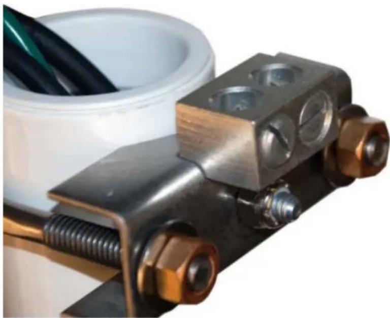
Install lightning rod as shown in FIGURE 6-40 (p. 57) and FIGURE 6-41 (p. 58).
- Carefully mount the lightning rod clamp to the top of the pole (FIGURE 6-40 (p. 57)). Position the clamp so it won't interfere with the connector cover.
natural_image
Close-up of a mechanical clamp or bracket assembly with brass bolts and metal components, partially covered by a white cylindrical container (no visible text or symbols)FIGURE 6-40. Lightning rod bracket installation
-
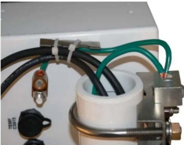
Strip 2.5 cm (1 in) from the top of the main green 10 AWG pole ground wire.
-
Insert the exposed wire into the empty clamp opening. Do not tighten the screw at this time (FIGURE 6-41 (p. 58)).
natural_image
Close-up of a laboratory instrument with black and green cables, no visible text or symbolsFIGURE 6-41. Grounding to lightning rod clamp
- Strip 2.5 cm (1 in) from both ends of the 23 cm (9 in) piece of 10 AWG green ground wire.
- Insert one end into the enclosure ground lug located at the top back of the enclosure.
- Put the other end in the same clamp opening as the main grounding wire and tighten down the screw (FIGURE 6-41 (p. 58)).
- Insert the lightning rod into the empty clamp opening. The milled flat side of the lightning rod should face the clamping screw.
- Tighten the screw to hold the rod firmly in place.
6.9 Solar panel installation
natural_image
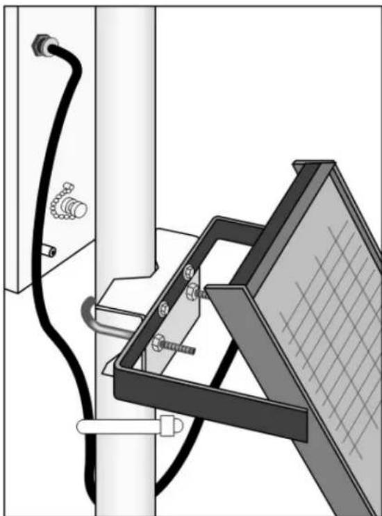
Technical diagram of a mechanical assembly with wires and components, no visible text or symbolsFIGURE 6-42. Solar panel mounting and cabling
- Mount the solar panel to the pole using the mounting brackets (FIGURE 6-42 (p. 59)).
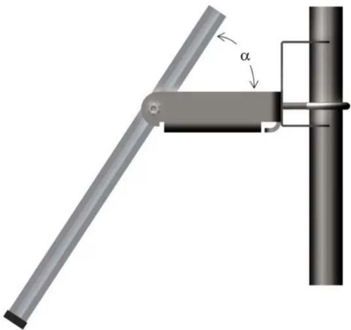
- Mount the solar panel to the pole so it faces south (northern hemisphere). Position it as high off the ground as practical, ensuring it cannot interfere with air flow or sunlight around the sensors. The solar panel should be oriented to receive maximum insolation over the course of the year. Suggested tilt angles referenced to the horizontal plane (FIGURE 6-43 (p. 60)) are listed in Table 6-1 (p. 59).
| Table 6-1: Latitude and solar panel tilt angle | |
| Latitude Tilt angle (α) | |
| 0 to 10 degrees 10 | degrees |
| 11 to 20 degrees Latitude + 5 degrees | |
| 21 to 45 degrees Latitude + 10 degrees | |
| 46 to 65 degrees | Latitude + 15 degrees |
| >65 degrees | 80 degrees |
natural_image
Mechanical lever mechanism diagram showing a rod pivoted at angle α and a vertical support structure (no text or symbols)FIGURE 6-43. Side view of solar panel shows tilt angle
- After determining the tilt angle, loosen the two bolts that attach the mounting bracket to the panel.
- Adjust the angle and tighten the bolts.
- Secure the wire to the mast using wire ties (FIGURE 6-43 (p. 60)).
- Connect the plug at the end of the solar panel cable to the Power connector. Make sure the plug is fully seated and the locking ring turned clockwise until it stops.
NOTE:
Schematics for the solar panel cable are in Power schematics (p. 78).
6.10 Battery installation
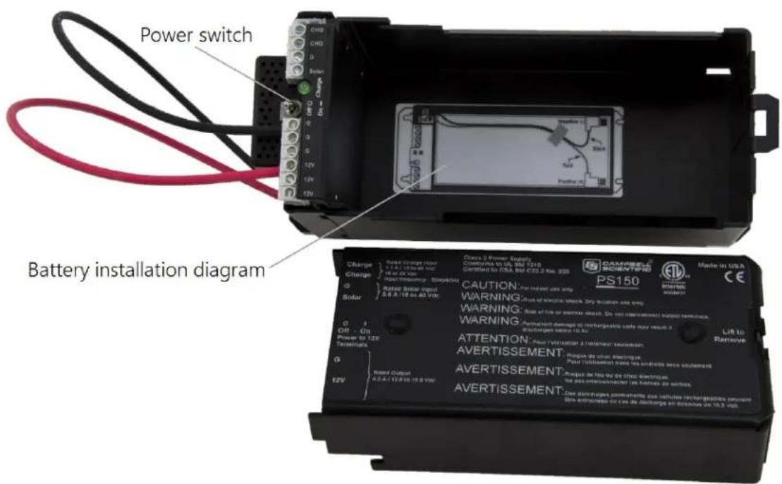
FIGURE 6-44. PS150 with lid open
- Move the PS150 power switch to the OFF position (FIGURE 6-44 (p. 61)).
- Remove the cover from the PS150 by sliding the latch up at one end of the cover and sliding the cover down and out (FIGURE 6-44 (p. 61)).
- Install the battery according to the diagram (FIGURE 6-44 (p. 61)).
- Plug the battery wire into the connector.
- Put the cover back on the PS150 and latch it in place.
NOTE:
Do not switch the power supply ON until AC or solar power has been connected to the back of the enclosure.
The green charge light on the PS150 will flash when charging voltage is present. The charge light is not affected by the switch. Switching on the power supply without a charging voltage will run the battery down.
FIGURE 6-45 (p. 62) shows factory wiring between the PS150 and the enclosure.
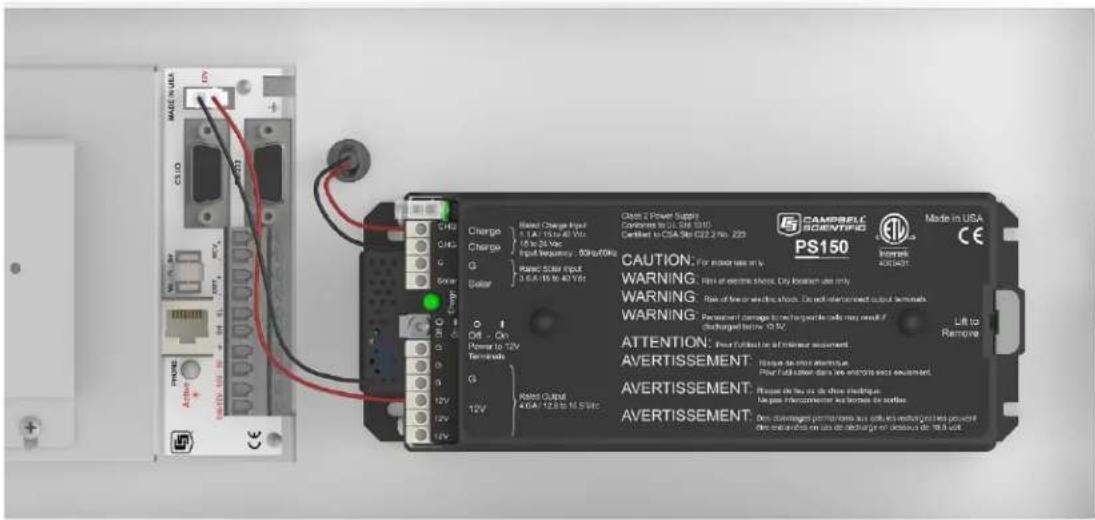
FIGURE 6-45. PS150 to WS-PRO2 enclosure wiring
6.11 Restraining cables
- Loosely wire tie power, communications, and grounding cable to the wire tie harness at the top of the back of the station (FIGURE 6-46 (p. 62)). Do NOT clip back the wire tie at this time.
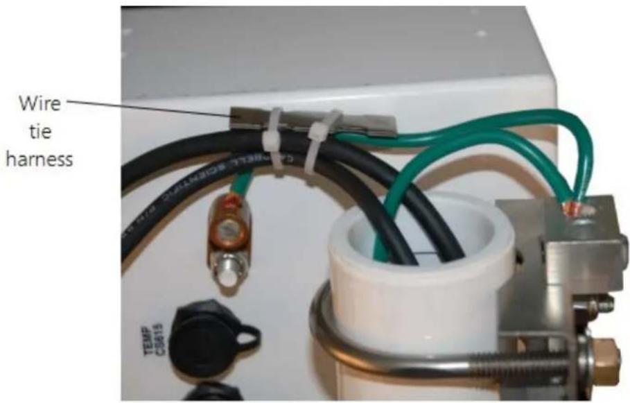
FIGURE 6-46. Cabling strapped to wire tie harness
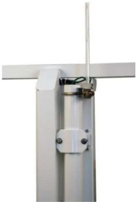
- Replace the connector cover. The tab at the top of the connector cover slides into the opening on the back of the crossarm. Ensure that all cables and connector caps are under the cover before tightening the Phillips screw at the bottom of the cover. Make sure that all cables coming out of the top right of the connector cover are not being pinched.
natural_image
Close-up of a metallic mechanical assembly with metal brackets and a central mounting bracket (no text or symbols visible)FIGURE 6-47. Connector cover in place
- Tighten the wire ties holding the cables to the wire tie harness and clip off excess ties (FIGURE 6-47 (p. 63)).
6.12 Sealing and desiccating the enclosure
The WS-PRO2 enclosure is supplied with two desiccant packs. The desiccant maintains a low humidity in the enclosure to minimize the chance of condensation on the instrumentation. Desiccant should be changed when the internal enclosure humidity sensor measures 50% or higher. Install the desiccant as shown in FIGURE 6-48 (p. 64). Keep unused desiccant tightly sealed in an airtight container.
NOTE:
Place the desiccant into the enclosure after all other weather station installation steps have been completed.
- Take the desiccant packs out of the plastic bag.
- Strap the packs into the desiccant holder inside the lid of the enclosure using the two Velcro straps.
- Close the enclosure hasp securely. A padlock may be used on the latch for extra security.
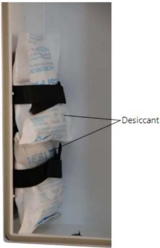
FIGURE 6-48. Desiccant installation
6.13 WS-PRO2 software
A variety of different software packages are available to work with the WS-PRO2 station. Contact Rain Bird as needed for support.
7. Maintenance and troubleshooting
NOTE:
All factory repairs and recalibrations require a returned material authorization (RMA) and completion of the "Declaration of Hazardous Material and Decontamination" form. Refer to the Assistance page at the end of this manual for more information.
7.1 Maintenance
Proper maintenance of the WS-PRO2 components is essential to obtain accurate data. Equipment must be in good operating condition, which requires a program of regular inspection and maintenance. Routine and simple maintenance can be accomplished by the person in charge of the weather station. More difficult maintenance such as sensor calibration, sensor performance testing, and sensor component replacement, generally requires a skilled technician, or that the instrument be sent to Campbell Scientific or the manufacturer. Refer to the Assistance page at the end of this document for the procedure of returning components to Campbell Scientific.
A station log should be maintained for each weather station that includes serial numbers, dates that the site was visited, and maintenance that was performed.
7.1.1 Pole maintenance
Periodically check the pole for structural damage, proper alignment, and for level/plumb.
7.1.2 Power supply maintenance
Rechargeable power supplies should be connected to an AC transformer or unregulated solar panel at all times. The PS150 green charge light will flash when voltage to the charging circuitry is present. The charge indicating light runs independent of the power switch. Be aware of battery voltage that consistently decreases over time, which indicates a failure in the charging circuitry. Short Cut and VisualWeather automatically program the weather station to measure battery voltage.
Occasionally clean the glass on the solar panel to improve its efficiency. Use warm mildly soapy water and a clean cloth. Rinse with clean water.
7.1.3 Desiccant
Humidity is monitored inside the WS-PRO2 enclosure using the Elan HM2000 RH sensor that is incorporated in the enclosure. Change the desiccant packs when the enclosure RH exceeds 50%. The enclosure RH sensor should be changed approximately every five years.
Desiccant packs may be ordered in quantity of 20 individually sealed packs at a time or by the individual pack.
7.1.4 Sensor maintenance
Perform sensor maintenance at regular intervals, depending on the desired accuracy and the conditions of use. A suggested maintenance schedule is outlined below. WS-PRO2 maintenance log (p. 103) provides an example of a maintenance log file for one year of station use.
1 week
- Check the rain gauge screen and funnel for debris and level.
1 month
- Check the solar radiation sensor (pyranometer) for level and contamination. Gently clean with blast of dry air, soft camel hair brush, or clean water if needed.
CAUTION:
Handle the pyranometer carefully when cleaning. Be careful not to scratch the surface of the sensor.
- Do a visual/audio inspection of the 034B-ET anemometer at low wind speeds. Worn bearings can cause the wind cups to spin in an uneven manner and/or make a grinding sound.
- Check the WindSonic1-ET for contamination. If needed, gently clean the WindSonic1 with a cloth and mild detergent.
CAUTION:
When cleaning the WindSonic1, do not use solvents and avoid scratching the sensor.
3 months
- Clean the radiation shield by removing the two knurled thumb screws holding it to the crossarm. Gently pull the sensor out of the shield. Clean the radiation shield using warm mildly soapy water. Rinse with clean water and allow the shield to dry before putting it back on the crossarm.
- If necessary, clean the white filter element on the end of the temp/RH sensor. To clean the filter, unscrew it from the end of the sensor and put it in a cup of CLEAN DISTILLED WATER. Use no soap. Agitate the filter in the cup of water. Remove the filter and allow to air dry before putting it back on the end of the sensor.
6 months
- Replace the anemometer bearings and reed switch on the 034B-ET if operating under harsh conditions, such as constant high winds, blowing dust, and/or salt spray contamination. Return the sensor to Campbell Scientific for bearing and reed switch replacement (see Assistance page).
1 year
- Replace the wind speed (anemometer) bearings on the 034B-ET. Return the sensor to Campbell Scientific for bearing replacement (see Assistance page).
- Replace reed switch the 034B-ET if needed. Return the sensor to Campbell Scientific for bearing replacement (see Assistance page).
- Check calibration of the HMP60-ETS Temp/RH sensor, which tends to drift up over time giving readings higher than 100%. Replace RH chip if necessary (refer to FIGURE 7-1 (p. 68) and Procedure for removing RH chip (p. 69)).
NOTE:
WS-PRO2 stations began shipping January 2014 with an updated radiation shield with knurled thumb screws, using the HMP60 ETS Temp/RH sensor. All information in this document is also pertinent for the HMP50-ET, HMP60-ET, and HMP60 ETR sensors.
- Replace desiccant in enclosure housing as needed.
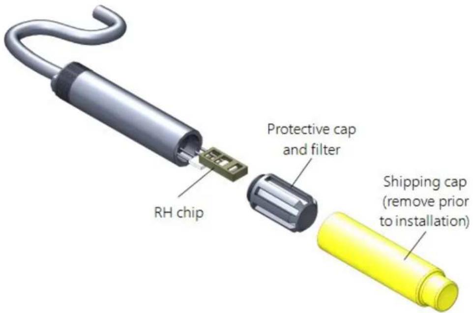
FIGURE 7-1. Exploded view of the temperature and RH sensor (adapter not shown)
2 years
- Replace vane potentiometer of the 034B-ET if needed (refer to www.campbellsci.com/order/034b-et for part number and price). To send the sensor to Campbell Scientific for potentiometer replacement, refer to the Assistance page.
- Replace enclosure gasket if necessary. Refer to the Assistance page if sending the enclosure to Campbell Scientific for gasket replacement. Refer to www.campbellsci.com/p10505 to replace gasket in the field.
3 years
- Send the solar radiation sensor (pyranometer) to Campbell Scientific for calibration (refer to the Assistance page). Sensor cannot be calibrated in the field. (Some users recommend calibrating this sensor on a yearly basis.)
4 to 5 years
- Check sensor cables (as well as all other cables) for cracking, deterioration, proper routing, and strain relief. Replace as required.
- Check enclosure relative humidity sensor. To check this sensor, take the lid off the enclosure during routine desiccant replacement and leave it off for 5 to 10 minutes before
putting in new desiccant. While the lid is off the enclosure, compare the internal enclosure humidity to the air humidity. Replace if >10% off.
7.1.4.1 Procedure for removing RH chip
- Unscrew the protective cap (see FIGURE 7-1 (p. 68)).
- Hold the plastic sides of the RH chip and unplug it.
CAUTION:
To prevent scratching, avoid touching the silver chip, and handle the RH chip with care.
- Rinse off the RH chip with distilled water or dispose of the old RH chip.
- Hold the sides of the rinsed or new chip and plug it in.
- Screw on the protective cap.
7.1.5 Data logger module
The data logger module contains a lithium battery that operates the clock and SRAM when the module is not powered. The data logger does not draw power from the lithium battery while it is powered by a 12 VDC supply. In an WS-PRO2 stored at room temperature, the lithium battery should last approximately 10 years (less at temperature extremes). Where the WS-PRO2 is powered most or all of the time, the lithium cell should last much longer.
While powered from an external source, the module measures the voltage of the lithium battery daily. This voltage is displayed in the status table. A new battery will have approximately 3.6 volts. The data logger Status Table has a "Lithium Battery" field. This field shows lithium battery voltage.
Send the WS-PRO2 enclosure to Campbell Scientific to have Campbell Scientific replace the battery when voltage is approximately 2.7 V (see Assistance page). If the lithium cell is removed or allowed to discharge below the safe level, the WS-PRO2 will still operate correctly while powered. Without the lithium battery, the clock will reset and data will be lost when power is removed.
CAUTION:
Campbell Scientific recommends factory replacement of the lithium battery. Misuse of the lithium battery in the data logger or installing this lithium battery improperly can cause severe injury. It is a fire, explosion, and severe burn hazard! Do not recharge, disassemble, heat above 100 °C (212 °F), solder directly to the cell, incinerate, nor expose contents to water. Lithium batteries need to be disposed of properly.
Table 7-1 (p. 70) lists the specifications of the battery.
| Table 7-1: Data logger lithium battery specifications | |
| Manufacturer Tadiran | |
| Model TL-59025 (3.6 V) | |
| Capacity 1.2 Ah | |
| Self-discharge rate 1%/year @ | 20 °C |
| Operating temperature range | -55 to 85 °C |
7.2 Troubleshooting
7.2.1 No response using the CR1000KD keypad 70
7.2.2 No response from data logger when using a communications peripheral 71
7.2.3 NAN, ±INF, or unreasonable results displayed in a variable or stored in a data table 72
7.2.4 WindSonic1-ET diagnostic codes 72
7.2.1 No response using the CR1000KD keypad
Check keypad response after each of the following steps.
- Make sure the battery has been installed and the PS150 power switch is set to ON (Battery installation (p. 61)).
- Use a voltmeter to measure the voltage on the 12V and G terminals (FIGURE 6-45 (p. 62)); the voltage must be from 9.6 to 16 VDC.
- Use a voltmeter to measure the voltage on the 5V and G terminals (FIGURE 6-45 (p. 62)); the voltage must be from 4.9 to 5.1 VDC.
- Disconnect the Temp/RH sensor from the back of the enclosure.
- Disconnect the 9-pin ribbon cable from any communications option used with the station so that only the keypad is attached to the 9-pin plug in the lower right corner of the enclosure.
- Cycle the power to the data logger by switching the PS150 power supply to OFF then to ON, or by disconnecting and reconnecting the battery plug. The keypad should power up and the Campbell Scientific logo and text should appear on the display.
- Call Rain Bird GSP if still no response.
7.2.2 No response from data logger when using a communications peripheral
At the data logger:
- Make sure the battery has been installed and the power switch set to ON (Battery installation (p. 61)).
- Use a voltmeter to measure the voltage on the 12V and G terminals (FIGURE 6-45 (p. 62)); the voltage must be between 9.6 and 16 VDC.
- Use a voltmeter to measure the voltage on the 5V and G terminals (FIGURE 6-45 (p. 62)); the voltage must be between 4.9 and 5.1 VDC.
- Make sure the data logger is connected to the communications peripheral, and the communications peripheral is properly installed and configured (Communications peripherals (p. 35)).
At the computer:
- Make sure calling software is properly configured (SmartWeather, Maxicom, IQ, etc.).
- Check the cable(s) between the serial port and the modem. If cables have not been purchased through Campbell Scientific, check for the following configuration using an ohm meter:
| 9-pin to 25-pin serial cable | |
| Computer end | Modem end |
| 2 | 3 |
| 3 | 2 |
| 4 | 20 |
| 5 | 7 |
-
Make sure the communications device at the computer is properly configured and cabled (Communications peripherals (p. 35)).
-
Call Rain Bird GSP if still no response.
7.2.3 NAN, ±INF, or unreasonable results displayed in a variable or stored in a data table
- Make sure the battery voltage is between 9.6 and 16 VDC.
- Verify sensors are plugged into the correct sensor connector and the locking ring is securely in place (see FIGURE 6-21 (p. 34)).
- Check connectors for any corrosion on pins.
- Inspect the sensor for damage and/or contamination. If damaged, contact Rain Bird GSP for repair or purchase of a replacement sensor.
7.2.4 WindSonic1-ET diagnostic codes
The WindSonic outputs a diagnostic code (Table 7-2 (p. 72)) with each wind direction and speed measurement. A data logger program can be written that filters out all data when the diagnostic is not 0. The programs can also report the number of good samples that were used in computing the on-line statistics. If the total number of good samples is less than 98% of the expected samples, the WindSonic may be in need of repair.
| Table 7-2: WindSonic Diagnostic Codes | ||
| Diagnostic Status Comment | ||
| 0 Okay | All okay | |
| 1 Axis 1 | Failed Insufficient samples, possible path obstruction | |
| 2 Axis 2 | Failed Insufficient samples, possible path obstruction | |
| 4 Both | Axis Failed Insufficient samples, possible path obstruction | |
| 8 NVM | error Nonvolatile Memory checksum failed | |
| 9 ROM | error Read Only | Memory checksum failed |
| 10 | Maximum Gain | Questionable wind measurements |
8. Schematics of connectors
Knowledge of schematics is not necessary for routine installation and maintenance. However, schematics may help with troubleshooting the WS-PRO2. Each connector has a small molded dot by pin 1. All of the schematics show the pinned connectors on the cables. Socketed connectors on the back of the enclosure are the mirror images of what is shown.
8.1 Sensor schematics
Temperature and Relative Humidity (RH) Sensor
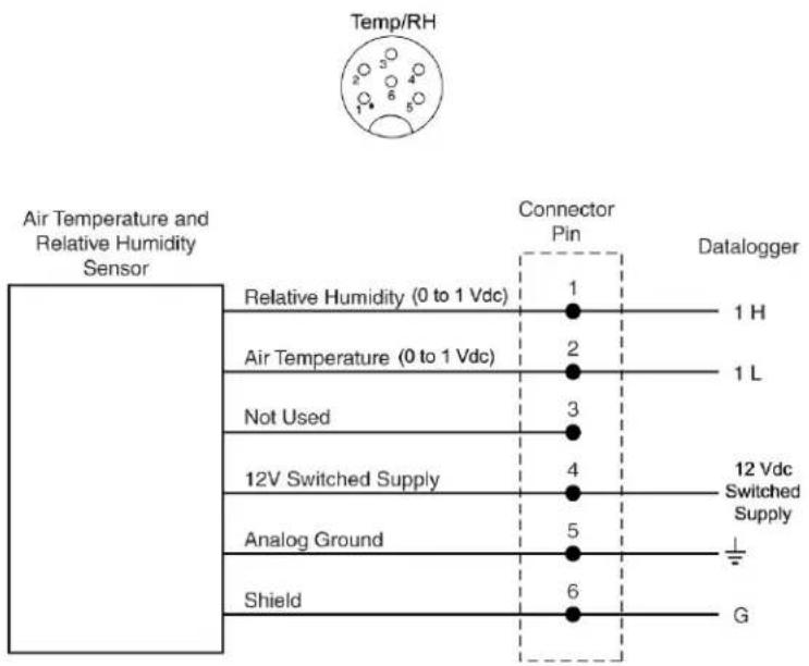
FIGURE 8-1. Schematic of HMP60-ETS RH and Temperature Probe and connector Temp/RH
Wind Speed and Wind Direction Sensor
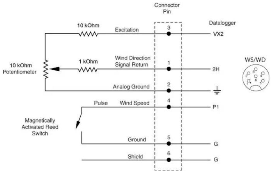
flowchart
graph TD
    A["10 kOhm Potentiometer"] --> B["10 kOhm"]
    B --> C["Excitation"]
    C --> D["Connector Pin 3"]
    D --> E["VX2"]
    A --> F["1 kOhm"]
    F --> G["Wind Direction Signal Return"]
    G --> H["Analog Ground 2"]
    H --> I["Pulse"]
    I --> J["Wind Speed 4"]
    J --> K["P1"]
    L["Magnetically Activated Reed Switch"] --> M["Ground 5"]
    M --> N["Shield 6"]
    N --> O["G"]
    P["WS/WD"] --> Q["G"]
FIGURE 8-2. Schematic of 034B-ET Wind Speed and Direction Probe and connector WS/WD
Temp/Sonic
Temperature or WindSonic
![Connector Pin Must be jumpered across pins 2 (center) and 3 (right) 1 Datalogger +12V Temperature Signal Return 2 5H 1KΩ Excitation 3 VX3 RS232 Recieve 4 RS232 COM 1 (TX) [C1] RS232 Transmit 5 RS232 COM 1 (RX) [C2] Ground 6 G](/content/2026/05/979288/images/0bfdadcc023b682221aa7e03bc2c6ad76812cc798e37905e8b81fd3c0c9a58e1.jpg)
FIGURE 8-3. Schematic of WindSonic1-ET Wind Sensor, soil temperature sensor (107 or 108), and connector Temp/Sonic
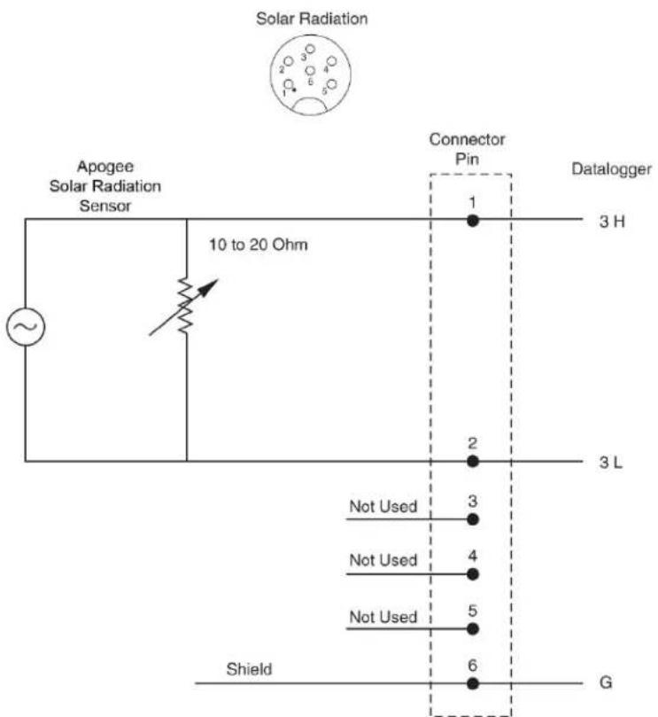
FIGURE 8-4. Schematic of CS305-ET Solar Radiation Sensor and connector Solar Radiation
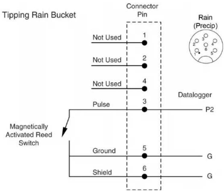
flowchart
graph TD
    A["Tipping Rain Bucket"] --> B["Connector Pin"]
    B --> C["Not Used 1"]
    B --> D["Not Used 2"]
    B --> E["Not Used 4"]
    B --> F["Pulse 3"]
    F --> G["Magnetically Activated Reed Switch"]
    G --> H["Ground 5"]
    G --> I["Shield 6"]
    J["Datalogger"] --> K["P2"]
    L["Rain (Precip)"] --> M["2 3 4 5"]
FIGURE 8-5. Schematic of TE525-ET Rain Sensor and connector Rain (Precip)
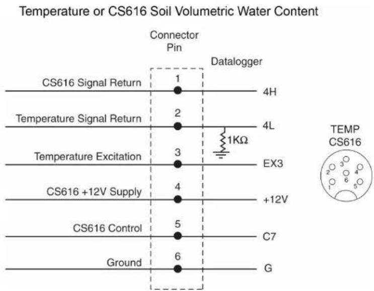
line
Temperature or CS616 Soil Volumetric Water Content | Signal | Pin | Datalogger | | :--- | :--- | :--- | | CS616 Signal Return | 1 | 4H | | Temperature Signal Return | 2 | 4L | | Temperature Excitation | 3 | 1KΩ | | CS616 +12V Supply | 4 | +12V | | CS616 Control | 5 | C7 | | Ground | 6 | G | TEMP CS616FIGURE 8-6. Schematic of 107 or 108 Temperature Sensor or CS616-LC Soil Volumetric Water Content Sensor and connector Temp/CS616
8.2 Power schematics
18 to 24 VRMS or 15 to 40 Vdc Solar Panel Power
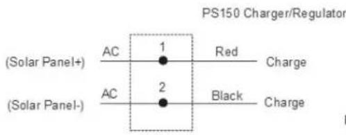
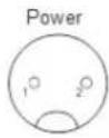
Note: PS150 Charger/Regulator is not sensitive to polarity.
FIGURE 8-7. Schematic of solar panel and connector Power
8.3 Communications modems schematics
Short-Haul or Phone Modem
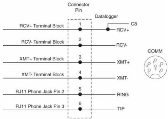
All Connections are surge protected using spark gaps
FIGURE 8-8. Schematic of short haul or phone modem and connector COMM
9. References
EPA, (1987). On-Site Meteorological Program Guidance for Regulatory Modeling Applications, EPA-450/4-87-013. Office of Air Quality Planning and Standards, Research Triangle Park, North Carolina 27711.
WMO, (1983). Guide to Meteorological Instruments and Methods of Observation. World Meteorological Organization No. 8, 5th edition, Geneva, Switzerland.
The State Climatologist, (1985) Publication of the American Association of State Climatologists: Height and Exposure Standards for Sensors on Automated Weather Stations, v. 9, No. 4 October, 1985.
EPA, (1989). Quality Assurance Handbook for Air Pollution Measurement Systems, EPA Office of Research and Development, Research Triangle Park, North Carolina 27711.
Appendix A. Grounding recommendations
A.1 Grounding system installation
To prevent lightning damage to your equipment, Rain Bird recommends installing a grounding system for the equipment (including controllers, weather stations, and central control systems). The grounding system discharges lightning-induced electrical current into the earth rather than allow the surge to pass through power wires or field wires to your equipment's electronic components.
A.1.1 Ground resistance
Ground resistance occurs when grounding system components, or the soil itself, oppose the flow of electricity into the earth. Ground resistance is measured in units called "ohms" (Ω). The higher the ground resistance (higher ohm readings), the less chance the surge will be shunted to ground rather than to the equipment's electronic components.
FIGURE A-1 (p. 81) shows points where grounding systems can develop resistance. To decrease ground resistance, Rain Bird recommends irrigating the soil around the grounding system. Each grounding system should have a dedicated irrigation zone with sprinkler heads and its own watering program to maintain soil moisture around the grounding system.
A properly installed grounding system should maintain a maximum ground resistance of 10 ohms or less. If you are unable to reach a resistance of 10 ohms or less, you can decrease resistance by surrounding the grounding rods or plates with ground enhancement material, such as POWER SET from Paige Electric Corporation (pn 1820058), or GEM from ERICO (pn GEM-25A).
If ground resistance still measures higher than 10 ohms, you can extend the ground rod length as described in "Ground Rod Stacking," or use additional grounding rods, as shown in grounding system design "Y" (Alternate).
A.1.2 Installation requirement
The following requirements apply to all grounding system designs (design Y and the "Grounding Plate" design). All grounding rods or plates must be connected together below grade with #6 AWG or larger solid bare copper wire.
Install the connecting wire in as straight a line as possible. If you must make a turn or bend in the wire, make the turn in a sweeping curve with a minimum radius of eight inches and a minimum included angle of 90^ .
To minimize resistance, the copper wire must be pre-welded to the grounding rods/plates, or welded to the rods/plates using an exothermic welding process at the site.
Make sure all welds are secure before burying the grounding rods. Rods and plates with welded joints do not need periodic visual inspection and can be fully buried (no valve box required). Measure the ground resistance around the grounding system after installation, and once every year after that.
NOTE:
The ground wire from the equipment to the grounding system should be as short as possible and have no bends, kinks, or coils in the wire.
Inspect the grounding system's clamped connections to the equipment (not the welded grounding system connections) once a year to make sure they are secure and corrosion-free.
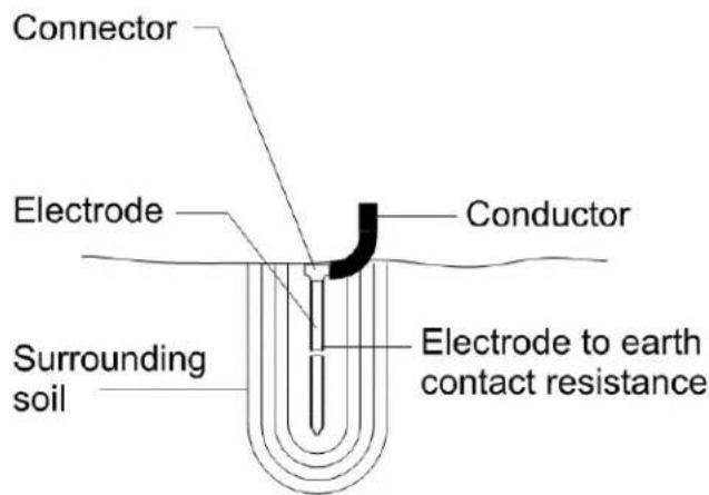
FIGURE A-1. Grounding systems can develop resistance at many points
A.1.3 Ground rod stacking
Threaded couplers (shown in FIGURE A-2 (p. 82)) are ground rod splices. If a single grounding rod fails to produce 10-ohm ground resistance (maximum), threaded couplers can be used to "stack" grounding rods.
NOTE:
Use threaded couplers made of the same material as your grounding rods.
Stacking ground rods increases the total effective rod length, decreasing ground resistance. Joining the rods together with threaded couplers forms a secure connection so the grounding rods can be assembled quickly and easily.
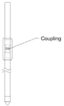
FIGURE A-2. Stacking grounding rods with threaded couplers can help decrease ground resistance
A.2 Grounding system designs
A.2.1 Design "Y"
Design "Y" (shown in FIGURE A-3 (p. 83) and FIGURE A-4 (p. 83)) consists of three, 5/8"-diameter x 8-foot-long, copper-clad grounding rods. Install the rods in a radial 1200 star ("Y") configuration. Each rod must be installed in a true vertical position, at least 16 feet from the equipment.
NOTE:
All grounding system diagrams are not to exact scale.
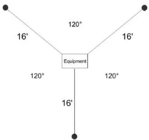
flowchart
graph TD
    A["Equipment"] -->|16'| B["16'"]
    A -->|120°| C["120°"]
    A -->|16'| D["16'"]
    A -->|120°| E["120°"]
FIGURE A-3. Design "Y" uses three groundings rods installed in radial 120 degrees "Y-shaped" configuration
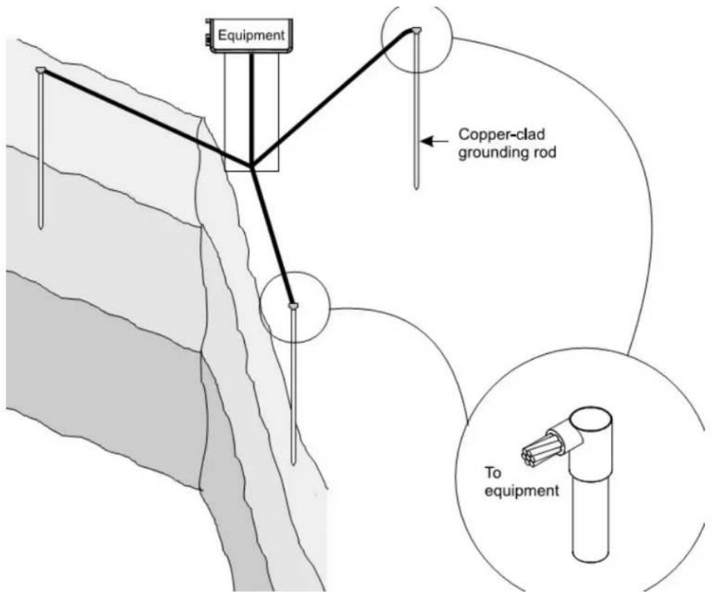
FIGURE A-4. Grounding system "Y can be installed as shown, or with ground enhancement material to reduce ground resistance even further
A.2.2 Design "Y" (alternate)
An alternate design "Y" (shown in FIGURE A-5 (p. 84) and FIGURE A-6 (p. 85)) uses three radials in a 120 degree star ("Y") arrangement. Each radial consists of three, 5/8" -diameter x 8-foot long copper-clad grounding rods. The first rod in each radial must be at least eight feet from the equipment. The rest of the rods must be at least 16 feet from any other rod.
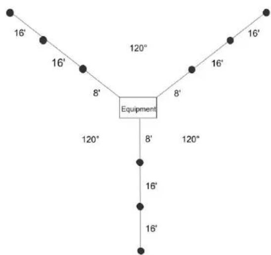
flowchart
graph TD
    A["Equipment"] --> B["16'"]
    A --> C["16'"]
    A --> D["8'"]
    A --> E["8'"]
    A --> F["120°"]
    A --> G["120°"]
    A --> H["120°"]
    A --> I["8'"]
    A --> J["16'"]
    A --> K["16'"]
    A --> L["16'"]
FIGURE A-5. Design "Y" (alternate) uses nine copper-clad grounding rods installed in a 120 degree star configuration
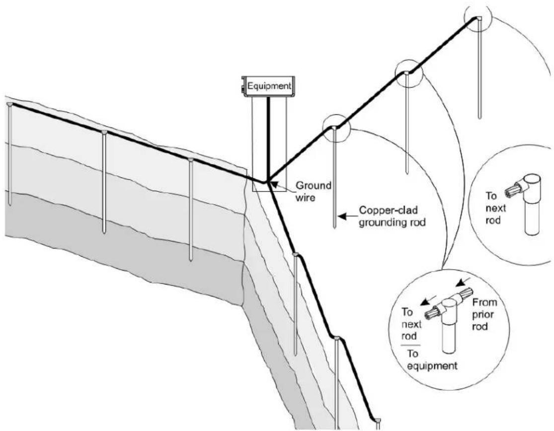
FIGURE A-6. The alternate version of grounding design "Y" uses nine grounding rods to reduce ground resistance
A.2.3 Grounding plate design
The "Grounding Plate" design (shown in FIGURE A-7 (p. 86) and FIGURE A-8 (p. 86)) consists of one vertical 8-foot copper-clad grounding rod at least eight feet from the equipment, and a copper grounding plate (minimum dimensions 4 × 96 × .0625 in). Install the grounding plate horizontally, three feet deep and 15 feet from the grounding rod.
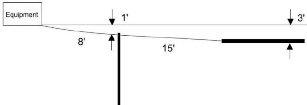
FIGURE A-7. The" Grounding Plate" design uses one copper-clad grounding rod and a rectangular copper grounding plate
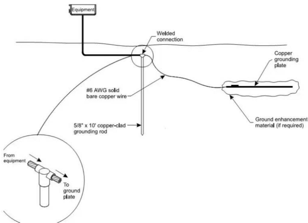
flowchart
graph TD
    A["Equipment"] --> B["Welded connection"]
    B --> C["#6 AWG solid bare copper wire"]
    C --> D["5/8" x 10' copper-clad grounding rod"]
    D --> E["Copper grounding plate"]
    E --> F["Ground enhancement material (if required)"]
    G["From equipment"] --> H["To ground plate"]
FIGURE A-8. The "Grounding Plate" design may be used with or without ground enhancement material, depending on side conditions
Appendix B. Determining True North and wind sensor orientation
The orientation of the WindSonic "North Arrow Markers" is found by reading a magnetic compass and applying the site-specific correction for magnetic declination; where the magnetic declination is the number of degrees between True North and Magnetic North. Magnetic declination for a specific site can be obtained from a USGS map, local airport, or through a NOAA web calculator (Online magnetic declination calculator (p. 89)). A general map showing magnetic declination for the Conterminous United States is shown in FIGURE B-1 (p. 87).
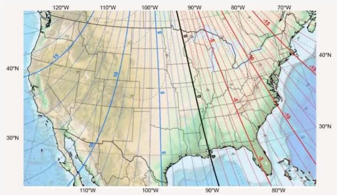
FIGURE B-1. Magnetic declination for the conterminous United States (2015)
Declination angles east of True North are considered negative, and are subtracted from 360 degrees to get True North as shown FIGURE B-2 (p. 88) (0° and 360° are the same point on a compass). Declination angles west of True North are considered positive, and are added to 0 degrees to get True North as shown in FIGURE B-3 (p. 88).
For example, the declination for Longmont, CO (10 June 2006) is 9.67°, thus True North is 360° – 9.67°, or 350.33° as read on a compass. Likewise, the declination for McHenry, IL (10 June 2006) is -2.68°, and True North is 0° – (-2.68°), or 2.68° as read on a compass.
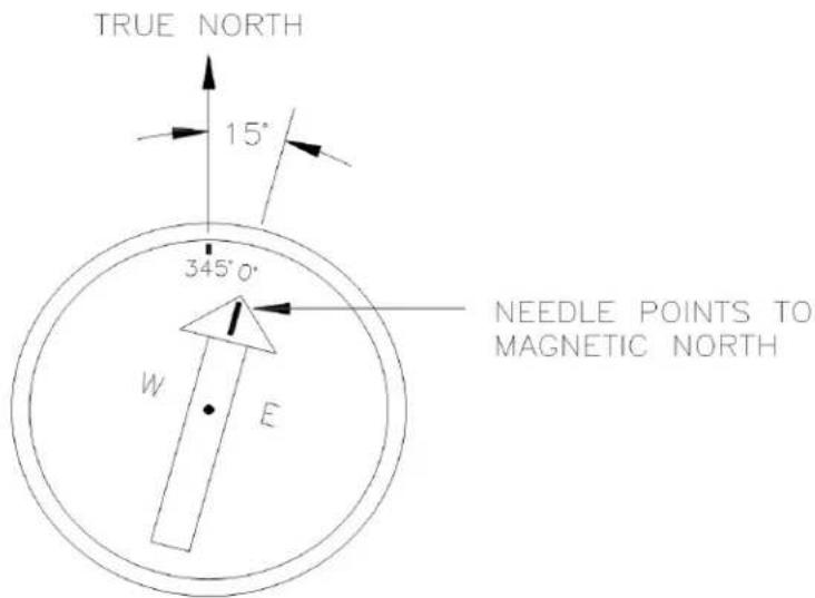
FIGURE B-2. A declination angle east of True North (positive) is subtracted from 360 (0) degrees to find True North
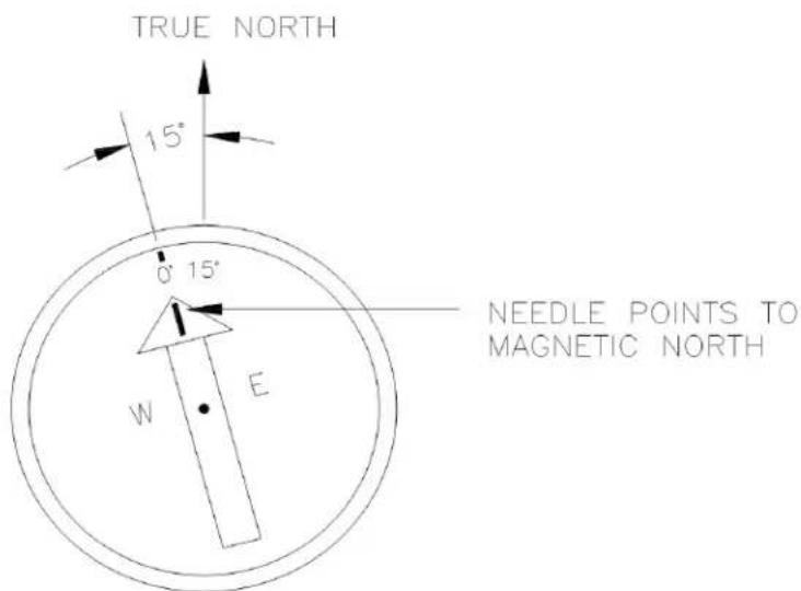
FIGURE B-3. A declination angle west of True North (negative) is subtracted from 0 (360) degrees to find True North
B.1 Online magnetic declination calculator
The magnetic declination calculator web calculator published by NOAA's Geophysical Data Center is available at: www.ngdc.noaa.gov/geomag/calculators/magcalc.shtml. This web page calculates declination based on the latitude and longitude. You can look up your site's latitude and longitude by entering the Zip Code or the Country and City, and then clicking the Get & Add Lat/Lon button (FIGURE B-4 (p. 89)). Click the Calculate button to get the magnetic declination.

NOAA NATIONAL CENTERS FOR ENVIRONMENTAL INFORMATION NATIONAL OCEANIC AND ATMOSPHERIC ADMINISTRATION
NOAA > NESDIS > NCEI (formerly NCDC) > Geomagnatism
Magnetic Field Calculators
Declination
U.S. Historic Declination
Magnetic Field
Magnetic Field Component Grid
Magnetic Declination Estimated Value
Declination is calculated using the most recent World Magnetic Model (WMM) or the International Geomagnetic Reference Field (IGRF) model. For 1590 to 1900 the calculator is based on the gufm1 model. A smooth transition from gufm1 to IGRF was imposed from 1890 to 1900. Declination results are typically accurate to 30 minutes of arc, but environmental factors can cause magnetic field disturbances.
Calculate Declination
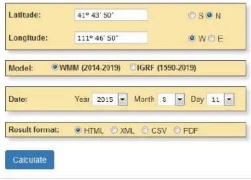
Lookup Latitude / Longitude
Either enter a zip code, select a country/city, or search for an address at USGS Earth Explorer.
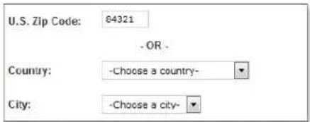
Get & Add Lat/Lon
FIGURE B-4. NOAA web calculator
FIGURE B-5 (p. 90) shows that the calculated declination for Logan, UT is 11.78 degrees (11 August 2015). The declination for Utah is positive (east of north), so True North for this site is 360 – 11.78, or 348.22 degrees. The annual change is – 6 minutes/year or 6 minutes west per year.
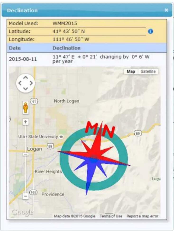
FIGURE B-5. NOAA calculated declination using HTML result format
Appendix C. PS24 24 Ah power supply with 10 x 12 inch enclosure
The PS24 Power Supply is typically used when a solar-powered WS-PRO2 transmits data using a wireless communications option. However, the PS24 can be used for any situation where a larger capacity battery is desirable.
C.1 PS24 components
The PS24 consists of a 24 Ah rechargeable battery in a 25 x 30 cm (10 x 12 in) environmental enclosure (FIGURE C-1 (p. 92) through FIGURE C-3 (p. 93)). Typically, the PS24 is ordered without a charging regulator and the PS100 or PS150 is moved from the station enclosure to the PS24 enclosure to serve as the charging regulator.
The battery should be recharged using AC power or solar power. An SP10 10-W solar panel, SP20 20-W solar panel, or wall charger is typically used to recharge the battery. The environmental enclosure is mounted to the WS-PRO2 pole using the mounting kit with hanger.
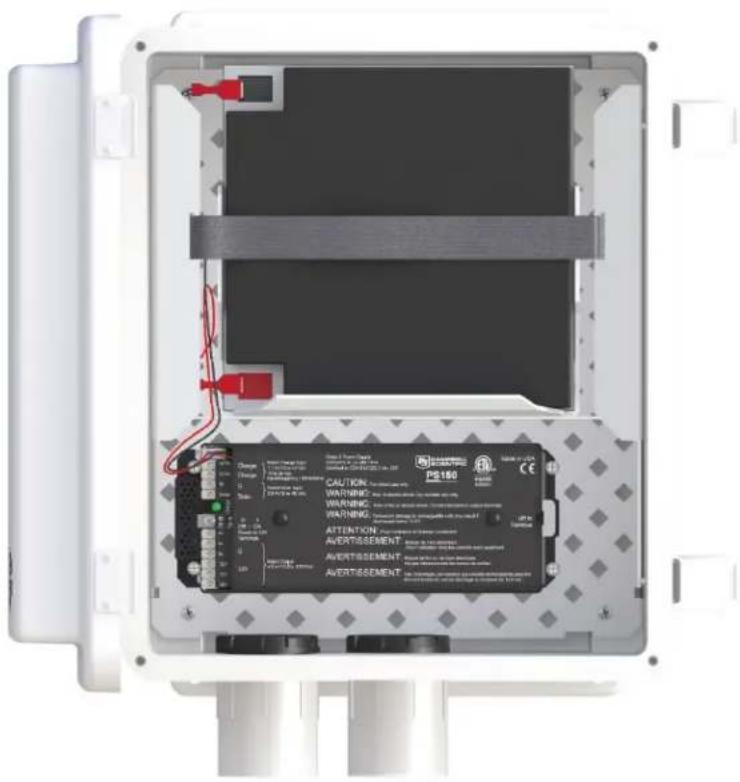
FIGURE C-1. PS24 enclosure with PS150 and battery bracket
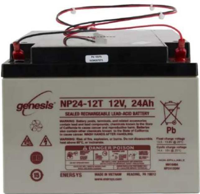
FIGURE C-2. 24 Ah battery and battery cable
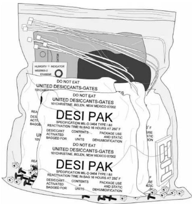
FIGURE C-3. Enclosure supply kit
C.2 PS24 installation
CAUTION:
The PS24 is purposely shipped without the battery mounted in its bracket. Do not install the battery until instructed to do so.
- Place the top enclosure bracket on the pole at approximately 10 m (3 ft) above the bottom of the pole. The bracket should be installed with the hook side up, and facing north.
- Slide the strut clamps into the bracket as shown in FIGURE C-4 (p. 94). Tighten the clamp so that it doesn't move.
CAUTION:
Do not over tighten the clamp!
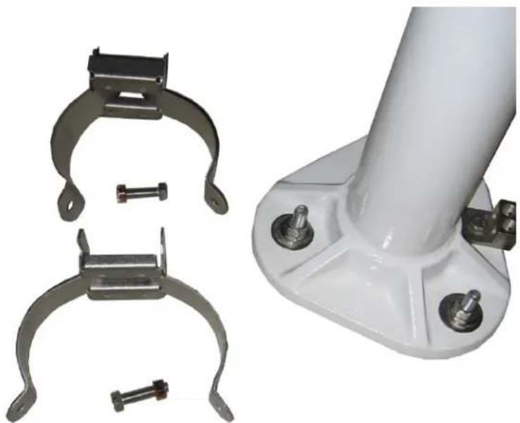
natural_image
Two metallic mechanical clamp brackets and a white cylindrical support bracket with mounting holes (no text or symbols visible)FIGURE C-4. Strut clamps in brackets
- Place the bottom strut clamp and bracket approximately 3 ~m (1 ft) below the top clamp. This clamp is installed with the hook side down. The bracket might have to be moved a little to accept the enclosure bracketing, so don't tighten the bracket yet. FIGURE C-5 (p. 94) shows the top and bottom brackets correctly positioned on the WS-PRO2 pole.
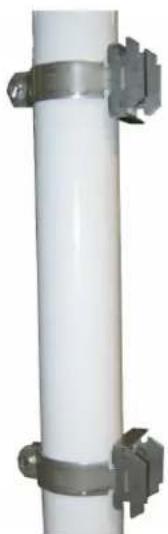
natural_image
Vertical white cylindrical pipe with metallic clamps attached (no text or symbols visible)FIGURE C-5. Both strut clamps and brackets on WS-PRO2 pole
- Hook the enclosure on the top bracket as shown in FIGURE C-6 (p. 95).
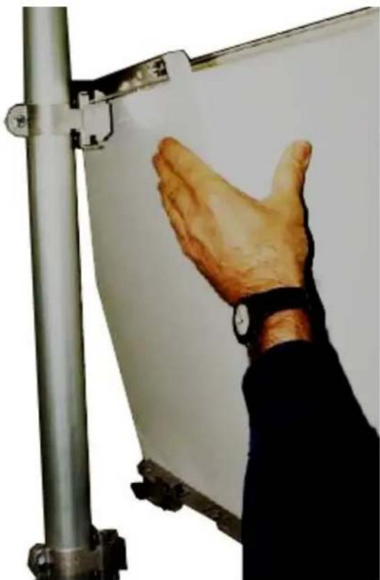
natural_image
Close-up of a hand touching a whiteboard with metal frame (no text or symbols visible)FIGURE C-6. Top clamp hook side up
- The bottom enclosure bracket should slide between the top lip of the bottom strut mount bracket and the notch directly below. Move the bottom bracket if necessary, then bolt the bottom bracket down (see FIGURE C-7 (p. 96)).
CAUTION:
Do NOT over tighten the bottom bracket.
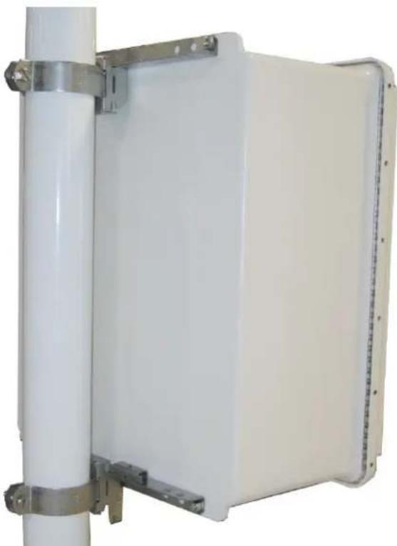
natural_image
White rectangular electronic panel mounted on a vertical pole with metal brackets (no text or symbols visible)FIGURE C-7. Enclosure mounted on WS-PRO2 pole
- The bottom enclosure bracket has a small metal locking mechanism. Push up on the small Phillips screw underneath the mechanism and slide it to the left. Once in place, put a small wire tie in the hole to the right of the locking mechanism (FIGURE C-8 (p. 97)).
NOTE:
To remove the enclosure from the bracketing, cut off the wire tie, slide the lock to the right, and lift the entire enclosure off the bracketing.
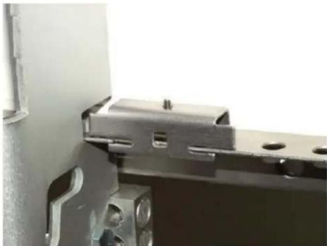
natural_image
Close-up of a metal bracket with mounting holes and a small cylindrical component, no visible text or symbols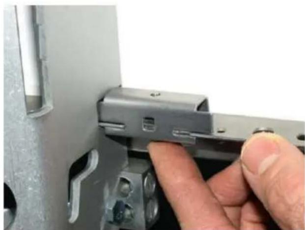
natural_image
Close-up of a hand inserting a component into a metal bracket (no visible text or symbols)FIGURE C-8. Enclosure locking mechanism
- Install the solar panel above the PS24 enclosure, and face the solar panel south (FIGURE C-9 (p. 98)).
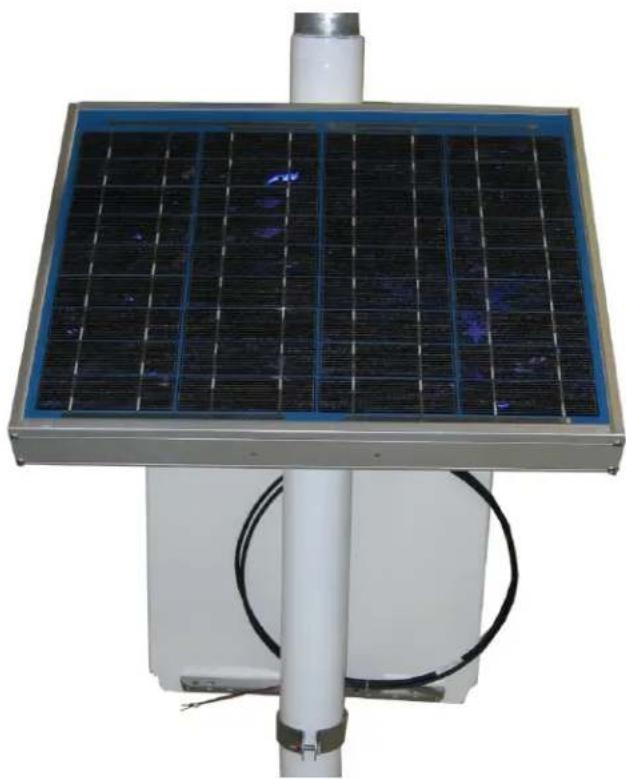
natural_image
Solar-powered smart grid mounted on a white base with a vertical pole and cable, no visible text or symbols.FIGURE C-9. Fully mounted solar panel
-
Place a blanket or box over the solar panel to prevent any voltage output.
-
Route the solar panel cable and power cable coming from the main WS-PRO2 enclosure into the conduit at the bottom of the PS24 enclosure.
TIP:
Leave a loop of all cables under the PS24 enclosure to act as a drip line. Cut both cables to whatever length you need. It doesn't hurt to leave a loop of cable inside the enclosure.
-
If this is a station retrofit, remove the PS100 or PS150 from the weather station enclosure and install it into the PS24 enclosure. Unplug the 7 Ah battery from the PS100 or PS150 and remove the battery from the battery compartment. The 7 Ah battery will not be used in the configuration.
-
Wire the charging source (solar panel or AC source) into the two CHG terminals on the CH150 or CHARGE terminals on the PS100 and PS150 (Table C-1 (p. 99)).
| Table C-1: Solar panel or AC connections | |
| Solar panel or AC wire color | Power supply connection terminal |
| Red CHG or CHARGE | |
| Black CHG or CHARGE | |
NOTE:
Polarity makes no difference. Connect one wire per CHG terminal block.
- If the charging source is a solar panel, remove the blanket or box from the solar panel once it's wired into the CH150, PS100 or PS150 regulator.
NOTE:
The charging LED (steady red on the PS100, or flashing green on the CH150 and PS150) indicates that the charging source (solar panel or AC) is providing a charging voltage to the battery. The battery will be charged regardless of the toggle switch position. The switch on the regulator controls the voltage going to the terminal blocks marked +12V on the PS100 and 12V on the CH150 and PS150.
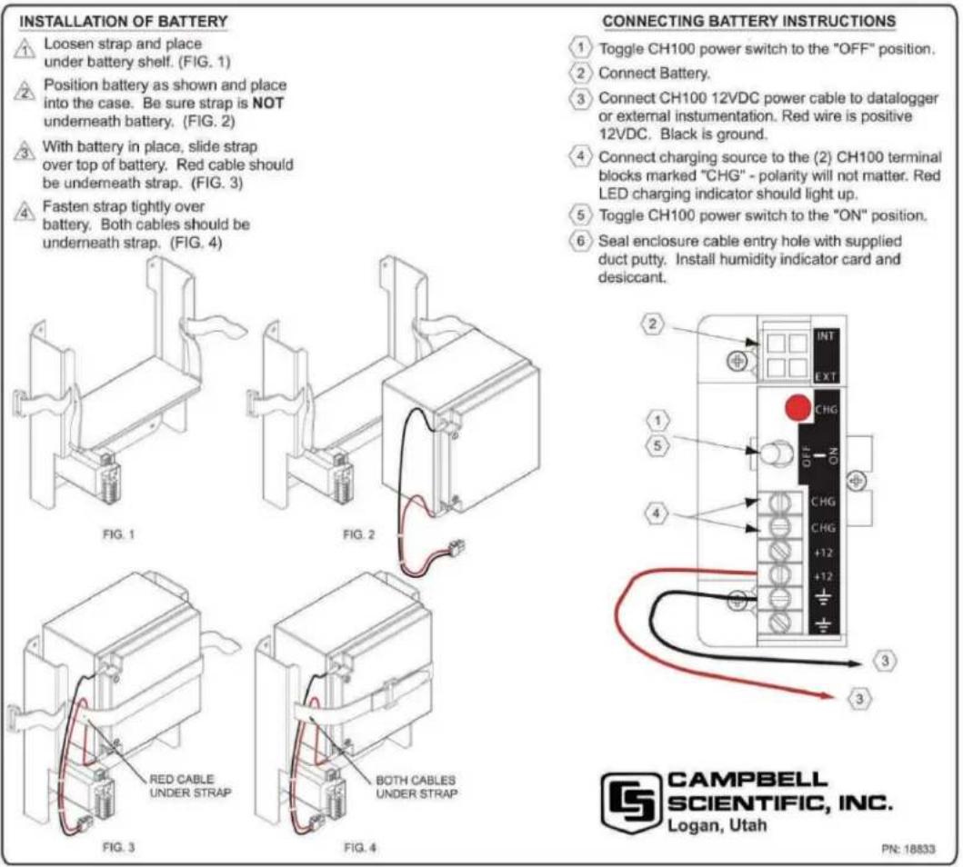
FIGURE C-10. Procedure for installing and connecting battery
NOTE:
The power cable that carries the regulated 12 VDC power from the regulator in the external enclosure to the WS-PRO2 station enclosure has a two-pin connector on one end and tinned wires on the other.
- Toggle the power switch on the regulator (CH100, PS100, CH150, or PS150) to the OFF position.
- Wire the power cable to the regulator (Table C-2 (p. 101)).
| Table C-2: Power cable-to-regulator connection | |
| Wire color Regulator connection terminal | |
| Red 12V or +12V | |
| Black G | |
-
Plug the two-pin connector into the POWER connector on the back of the station.
-
Plug the connector on the BP24 24 Ah battery wiring harness into the only battery connector on the CH150 or PS150 (located adjacent to the charge ports) or into the Battery – Internal connector on the PS100 or the INT connector on the CH100.
NOTE:
Since the power coming into the enclosure is regulated power coming from the external enclosure, the wiring inside the WS-PRO2 station enclosure needs to be different than the standard wiring.
- If this is a retrofit, inside of the ET station enclosure, wires come through the enclosure wall from the POWER connector on the back of the station that used to be wired into the charge ports of the PS100 or PS150. You have three options:
a. If you received a new POWER connector with your kit, remove the old POWER connector by removing the plastic nut on the back of the station that holds the POWER connector in place. Remove the old connector and replace it with the new one, placing the foam washer inside the enclosure. Tighten the plastic nut. Plug the plastic plug of the new POWER connector into the 12V port.
b. If you're working with the original POWER connector, connect the black wire of the POWER connector to the ground connector on the gray terminal strip, and the red wire to the 12V connector on the terminal strip. The wire and plug previously used with the PS100 or PS150 can be discarded
c. If you're experienced with electrical work, butt splice the wires of the POWER connector onto the wires from the harness assembly removed from the 7 amp hour battery (red to red and black to black). Plug the plastic plug into the 12V terminal.
-
An extra loop of ground wire was sent with the station. Use it to ground the enclosure to the grounding rod system. The external ground lug is mounted on the bottom left corner of the PS24 enclosure.
-
Move the switch to the ON position, and test the station.
-
After everything checks out, find the gray duct putty that was included in the enclosure supply kit. Seal the cable-entry conduit by placing putty on the inside and outside of it. Push the putty down into the cable entries.
CAUTION:
The enclosure needs to be sealed up tight, so don't be stingy with the putty.
-
Put both bags of desiccant inside of the enclosure.
-
Stick the humidity indicator card on a wall inside of the enclosure.
CAUTION:
Pink on the humidity indicator card means it's time to change the desiccant. Change the desiccant at least every year. However, it's often wise to change the desiccant every six months.
- Close the lids on the external enclosure and the WS-PRO2 enclosure.
Appendix D. WS-PRO2 maintenance log
Sensor installation date: ____
| Clean/inspect rain gauge sensor (recommended – weekly) | |||
| Date OK/comments | Date OK/comments | ||
| Clean/inspect rain gauge sensor (recommended – weekly) | ||||
| Date OK/comments | Date OK/comments | |||
| Clean/inspect solar radiation sensor (recommended – monthly) | |
| Date OK/comments | |
| Clean/inspect temp/RH sensor and radiation shield (recommended – quarterly) | |
| Date OK/comments | |
| Replace wind speed bearings and reed switch (recommend – yearly) | |
| Date OK/comments | |
| Replace RH chip in the HMP60-ETS temp/RH sensor (recommended – yearly) | |
| Date OK/comments | |
| Replace desiccant bags (qty 2) inside enclosure (recommended – yearly) | |
| Date OK/comments | |
| Calibrate solar radiation sensor (CS305-ET) (recommended – every 3 years) | |
| Date OK/comments | |
Limited warranty
Products manufactured by Campbell Scientific are warranted by Campbell Scientific to be free from defects in materials and workmanship under normal use and service for twelve months from the date of shipment unless otherwise specified on the corresponding product webpage. See Product Details on the Ordering Information pages at www.campbellsci.com ↗. Other manufacturer's products, that are resold by Campbell Scientific, are warranted only to the limits extended by the original manufacturer.
Refer to www.campbellsci.com/terms#warranty for more information.
CAMPBELL SCIENTIFIC EXPRESSLY DISCLAIMS AND EXCLUDES ANY IMPLIED WARRANTIES OF MERCHANTABILITY OR FITNESS FOR A PARTICULAR PURPOSE. Campbell Scientific hereby disclaims, to the fullest extent allowed by applicable law, any and all warranties and conditions with respect to the Products, whether express, implied or statutory, other than those expressly provided herein.
Assistance
Products may not be returned without prior authorization.
Products shipped to Campbell Scientific require a Returned Materials Authorization (RMA) or Repair Reference number and must be clean and uncontaminated by harmful substances, such as hazardous materials, chemicals, insects, and pests. Please complete the required forms prior to shipping equipment.
Campbell Scientific regional offices handle repairs for customers within their territories. Please see the back page for the Global Sales and Support Network or visit
www.campbellsci.com/contact to determine which Campbell Scientific office serves your country.
To obtain a Returned Materials Authorization or Repair Reference number, contact your CAMPBELL SCIENTIFIC regional office. Please write the issued number clearly on the outside of the shipping container and ship as directed.
For all returns, the customer must provide a "Statement of Product Cleanliness and Decontamination" or "Declaration of Hazardous Material and Decontamination" form and comply with the requirements specified in it. The form is available from your CAMPBELL SCIENTIFIC regional office. Campbell Scientific is unable to process any returns until we receive this statement. If the statement is not received within three days of product receipt or is incomplete, the product will be returned to the customer at the customer's expense. Campbell Scientific reserves the right to refuse service on products that were exposed to contaminants that may cause health or safety concerns for our employees.
DANGER — MANY HAZARDS ARE ASSOCIATED WITH INSTALLING, USING, MAINTAINING, AND WORKING ON OR AROUND TRIPODS, TOWERS, AND ANY ATTACHMENTS TO TRIPODS AND TOWERS SUCH AS SENSORS, CROSSARMS, ENCLOSURES, ANTENNAS, ETC. FAILURE TO PROPERLY AND COMPLETELY ASSEMBLE, INSTALL, OPERATE, USE, AND MAINTAIN TRIPODS, TOWERS, AND ATTACHMENTS, AND FAILURE TO HEED WARNINGS, INCREASES THE RISK OF DEATH, ACCIDENT, SERIOUS INJURY, PROPERTY DAMAGE, AND PRODUCT FAILURE. TAKE ALL REASONABLE PRECAUTIONS TO AVOID THESE HAZARDS. CHECK WITH YOUR ORGANIZATION'S SAFETY COORDINATOR (OR POLICY) FOR PROCEDURES AND REQUIRED PROTECTIVE EQUIPMENT PRIOR TO PERFORMING ANY WORK.
Use tripods, towers, and attachments to tripods and towers only for purposes for which they are designed. Do not exceed design limits. Be familiar and comply with all instructions provided in product manuals. Manuals are available at www.campbellsci.com. You are responsible for conformance with governing codes and regulations, including safety regulations, and the integrity and location of structures or land to which towers, tripods, and any attachments are attached. Installation sites should be evaluated and approved by a qualified engineer. If questions or concerns arise regarding installation, use, or maintenance of tripods, towers, attachments, or electrical connections, consult with a licensed and qualified engineer or electrician.
General
- Protect from over-voltage.
- Protect electrical equipment from water.
- Protect from electrostatic discharge (ESD).
- Protect from lightning.
- Prior to performing site or installation work, obtain required approvals and permits. Comply with all governing structure-height regulations.
- Use only qualified personnel for installation, use, and maintenance of tripods and towers, and any attachments to tripods and towers. The use of licensed and qualified contractors is highly recommended.
- Read all applicable instructions carefully and understand procedures thoroughly before beginning work.
- Wear a hardhat and eye protection, and take other appropriate safety precautions while working on or around tripods and towers.
- Do not climb tripods or towers at any time, and prohibit climbing by other persons. Take reasonable precautions to secure tripod and tower sites from trespassers.
- Use only manufacturer recommended parts, materials, and tools.
Utility and Electrical
- You can be killed or sustain serious bodily injury if the tripod, tower, or attachments you are installing, constructing, using, or maintaining, or a tool, stake, or anchor, come in contact with overhead or underground utility lines.
- Maintain a distance of at least one-and-one-half times structure height, 6 meters (20 feet), or the distance required by applicable law, whichever is greater, between overhead utility lines and the structure (tripod, tower, attachments, or tools).
- Prior to performing site or installation work, inform all utility companies and have all underground utilities marked.
- Comply with all electrical codes. Electrical equipment and related grounding devices should be installed by a licensed and qualified electrician.
- Only use power sources approved for use in the country of installation to power Campbell Scientific devices.
Elevated Work and Weather
• Exercise extreme caution when performing elevated work.
- Use appropriate equipment and safety practices.
- During installation and maintenance, keep tower and tripod sites clear of un-trained or non-essential personnel. Take precautions to prevent elevated tools and objects from dropping.
- Do not perform any work in inclement weather, including wind, rain, snow, lightning, etc.
Maintenance
- Periodically (at least yearly) check for wear and damage, including corrosion, stress cracks, frayed cables, loose cable clamps, cable tightness, etc. and take necessary corrective actions.
• Periodically (at least yearly) check electrical ground connections.
Internal Battery
- Be aware of fire, explosion, and severe-burn hazards.
- Misuse or improper installation of the internal lithium battery can cause severe injury.
- Do not recharge, disassemble, heat above 100 °C (212 °F), solder directly to the cell, incinerate, or expose contents to water. Dispose of spent batteries properly.
WHILE EVERY ATTEMPT IS MADE TO EMBODY THE HIGHEST DEGREE OF SAFETY IN ALL CAMPBELL SCIENTIFIC PRODUCTS, THE CUSTOMER ASSUMES ALL RISK FROM ANY INJURY RESULTING FROM IMPROPER INSTALLATION, USE, OR MAINTENANCE OF TRIPODS, TOWERS, OR ATTACHMENTS TO TRIPODS AND TOWERS SUCH AS SENSORS, CROSSARMS, ENCLOSURES, ANTENNAS, ETC.
The Intelligent Use of Water.™
LEADERSHIP · EDUCATION · PARTNERSHIPS · PRODUCTS
At Rain Bird, we believe it is our responsibility to develop products and technologies that use water efficiently. Our commitment also extends to education, training and services for our industry and our communities.
The need to conserve water has never been greater. We want to do even more, and with your help, we can. Visit www.rainbird.com for more information about The Intelligent Use of Water."

Rain Bird Corporation
6991 E. Southpoint Road
Tucson, AZ 85756
Phone: (520) 741-6100
Fax: (520) 741-6522
Rain Bird Technical Services
(800) RAINBIRD (U.S. and Canada)
Rain Bird Corporation
970 West Sierra Madre Avenue
Azusa, CA 91702
Phone: (626) 812-3400
Fax: (626) 812-3411
Specification Hotline
800-458-3005 (U.S. and Canada)
Rain Bird International, Inc.
1000 West Sierra Madre
Azusa, CA 91702
Phone: (626) 963-9311
Fax: (626) 852-7343
www.rainbird.com
- WS-PRO2 Golf Course Weather Station
- Table of contents
- Maintenance and troubleshooting 65
- Schematics of connectors 73
- References 79
- Appendix A. Grounding recommendations 80
- Appendix B. Determining True North and wind sensor orientation 87
- Appendix C. PS24 24 Ah power supply with 10 x 12 inch enclosure 91
- Appendix D. WS-PRO2 maintenance log 103
- Introduction
- Precautions
- Initial inspection
- QuickStart
- User-supplied tools
- Supplies for power and communications options
- NOTE:
- Phone Modem
- Short-Haul Modem
- Radio
- Siting and exposure
- DANGER:
- Wind speed and direction
- Temperature and relative humidity
- Solar radiation
- Installation
- Base foundation installation
- Pole installation
- Pole grounding
- Enclosure installation
- AC power installation procedure
- CAUTION:
- Crossarm installation procedure
- Sensor installation
- RH and temperature radiation shield installation procedure
- 034B Wind Sensor (wind sensor option -MW)
- WARNING:
- WindSonic 2-D Ultrasonic Wind Sensor (wind sensor option -GW)
- Changing the jumper
- WindSonic attachment to crossarm
- Rain gauge
- Pyranometer
- 107 or 108 soil temperature sensor (optional)
- Sensor connections
- Sensor verification and clock set
- Communications peripherals
- Direct connect to WS-PRO2 station
- Phone modem
- Internal installation of phone modem
- External installation of phone modem
- Short-haul modem
- Internal installation of short haul modem
- External installation of short haul modem
- Radio
- Example radio configuration and power usage
- Internal installation of the radio
- External installation of the radio
- Base radio installation
- WS-PRO2 cell phone accessory kit
- Cellular modems available from Campbell Scientific
- Power considerations
- Antenna
- Establishing cellular service and configuring the cellular modem
- Internal installation of the cellular modem
- External installation of a cellular modem
- NL241 Wi-Fi accessory kit
- Antenna
- Power considerations
- Internal installation of Wi-Fi modem
- External installation of the Wi-Fi modem
- Lightning rod installation
- Solar panel installation
- Battery installation
- Restraining cables
- Sealing and desiccating the enclosure
- WS-PRO2 software
- Maintenance and troubleshooting
- Maintenance
- Pole maintenance
- Power supply maintenance
- Desiccant
- Sensor maintenance
- week
- month
- months
- months
- year
- years
- years
- to 5 years
- Procedure for removing RH chip
- Data logger module
- Troubleshooting
- No response using the CR1000KD keypad
- No response from data logger when using a communications peripheral
- At the data logger:
- At the computer:
- NAN, ±INF, or unreasonable results displayed in a variable or stored in a data table
- WindSonic1-ET diagnostic codes
- Schematics of connectors
- Sensor schematics
- Power schematics
- Communications modems schematics
- References
- Appendix A. Grounding recommendations
- A.1 Grounding system installation
- A.1.1 Ground resistance
- A.1.2 Installation requirement
- A.1.3 Ground rod stacking
- A.2 Grounding system designs
- A.2.1 Design "Y"
- A.2.2 Design "Y" (alternate)
- A.2.3 Grounding plate design
- Appendix B. Determining True North and wind sensor orientation
- B.1 Online magnetic declination calculator
- Magnetic Field Calculators
- Magnetic Declination Estimated Value
- Appendix C. PS24 24 Ah power supply with 10 x 12 inch enclosure
- C.1 PS24 components
- C.2 PS24 installation
- TIP:
- Appendix D. WS-PRO2 maintenance log
- Limited warranty
- Assistance
- General
- Utility and Electrical
- Elevated Work and Weather
- Maintenance
- Internal Battery
- The Intelligent Use of Water.™
Brand : RAIN BIRD
Model : WS-PRO2
Category : Weather Station