
ESP-SITE - Irrigation system RAIN BIRD - Free user manual and instructions
Find the device manual for free ESP-SITE RAIN BIRD in PDF.


| Product Type | Irrigation Controller |
| Brand | Rain Bird |
| Model | ESP-SITE |
| Number of Stations | 8 (expandable up to 12) |
| Power Supply | 24 VAC, 60 Hz (transformer included) |
| Dimensions (H x W x D) | 8.5 x 6.25 x 3.5 inches |
| Weight | 1.2 lbs (without transformer) |
| Programming | Easy-dial interface with LCD display |
| Watering Schedules | Up to 3 independent programs (A, B, C) |
| Watering Duration | 1 minute to 6 hours per station |
| Rain Sensor Compatible | Yes (normally closed sensor input) |
| Manual Operation | Individual station or all stations |
| Seasonal Adjustment | 0% to 200% (10% increments) |
| Water Budgeting | Per program percentage adjustment |
| Delay Between Stations | 0-9 seconds (programmable) |
| Cycle and Soak | Available for heavy soils or slopes |
| Start Times | Up to 4 start times per program |
| Non-Volatile Memory | Retains settings without battery |
| Indoor/Outdoor Use | Indoor only (weatherproof enclosure optional) |
| Warranty | 2 years limited |
Frequently Asked Questions - ESP-SITE RAIN BIRD
User questions about ESP-SITE RAIN BIRD
0 question about this device. Answer the ones you know or ask your own.
Ask a new question about this device
Download the instructions for your Irrigation system in PDF format for free! Find your manual ESP-SITE - RAIN BIRD and take your electronic device back in hand. On this page are published all the documents necessary for the use of your device. ESP-SITE by RAIN BIRD.
USER MANUAL ESP-SITE RAIN BIRD
Operations Guide ESP-MC, ESP-SAT, ESP-SITE-Satellite and Maxicom Interface Board (MIB) Kit

P/N 634593 REV F
Special Upgrade Offer
Save an extra 15% off new sprinkler timers and irrigation controllers at the Rain Bird Online Store.\*
Still struggling with your old sprinkler timer? Having a hard time complying with local watering restrictions? Upgrading to a new Rain Bird sprinkler timer is easier than you might think.
New timers are easier to program than ever before, with powerful features to help save you time and water while keeping your yard healthy and vibrant.
There are lots of models to meet your needs, including indoor and outdoor versions, flexible modular timers and even smart controllers that automatically adjust themselves based on the weather.
Shop Now at store.rainbird.com and enjoy exclusive upgrade savings!

Enter discount code:
UPGRADE15
at checkout to save an extra 15% off*
* Additional discount not valid on clearance items, bundles or store specials. Discount applies to controller products only. Cannot be combined with other store discount codes. Valid at the Rain Bird Online Store only. Subject to change without notice.
RAIN BIRD®
Safety Information
Warning!
Important safety information and warning messages appear throughout this manual. To ensure correct operation and to avoid additional expense, read this manual thoroughly before you begin installation.
"WARNING: A CIRCUIT BREAKER OR CUTOFF SWITCH IS TO BE PROVIDED IN THE FIXED WIRING TO ISOLATE THE CONTROLLER"
"MEMORY IS RETAINED BY A BATTERY WHICH IS TO BE DISPOSED OF IN ACCORDANCE WITH LOCAL REGULATIONS"
"ATTENTION: UN DISJONCTEUR OU UN IMTERRUPTEUR DOIT ETRE INSTALLE SUR LE PRIMAIRE POUR ISOLER LE PROGRAMMATEUR"
"LA MEMOIRE EST MAINTENUE GRACE A UNE BATTERIE RECHARGEABLE A DISPOSER SELON LA REGLEMENTATION LOCALE"
Caution icons

The lightening flash with arrowhead symbol, within an equilateral triangle, is intended to alert the user to the presence of uninsulated “dangerous voltage” within the product’s enclosure that may be of sufficient magnitude to constitute a risk of electric shock to persons.

The exclamation point within an equilateral triangle is intended to alert the user to the presence of important operating and maintenance (servicing) instructions in the literature accompanying the product.

Welcome to Rain Bird 1
The ESP-MC Controller ....1
The ESP-SAT Controller ....1
The Maxicom² Interface Board (MIB) .....1
The ESP-SITE-Satellite Controller ....1
Special Features 2
*For installation instructions see poster included in controller box
Looking at the Controller's Faceplate ....3
Rain Bird RASTER™ (Rapid Station Test Routine) 7
Introduction 7
RASTER™ Operation 8
Beginning the RASTER™ 8
Station Valve Testing 10
Troubleshooting Open and Shorted Valve Circuits 11
Open Circuits 11
Short Circuits 12
Troubleshooting Opens and Shorts 12
Programming the Controller 13
Preparing to Program the Controller 13
Setting the Time and Date 14
Setting up a Program 15
Step 1: Selecting a Program .....15
Step 2: Selecting the Cycle .....15
Step 3: Setting the Length of a Station's Watering Time .....17
Step 4: Setting Watering Start Times .....17
Step 5: Setting Programs to Stack or Overlap .....18
Step 6: Setting the MV/PUMP Start .....18
Setting Rain Delay 19
Setting Cycle + SoakTM 19
Setting the Water Budget ....20
Setting Event Day Off 21
Contents, continued
Setting a Delay between Stations ....21
Clearing All Programs 22
Operating the Controller 23
Operating Automatically ....24
Operating Manually 24
Operating a Program or Programs Manually .....24
Operating a Station or Stations Manually 25
Using the Test Program 25
Using the Sensor Option 26
Fuse Detection 26
Using the Diagnostic Circuit Breaker 26
Replacing the Battery .....26
Troubleshooting 27
General Troubleshooting 27
Maxicom²-specific Troubleshooting ....30
Appendix A: Scheduling Chart .....31
ESP-MC and ESP-SAT Controllers ....34
Appendix B: Maxicom ^2 Central Control System Overview .....34
ESP-SITE-Satellite Controller 36
Appendix C: Setting the Channel Number .....38
Appendix D: ESP-MC Controller Spare Parts List .....39
Glossary 40
Service Information 44
Warranty .... inside back cover
Introduction
Welcome to Rain Bird
Thank you for purchasing your new, state-of-the-art Rain Bird controller. For more than six decades, Rain Bird has led the irrigation industry in meeting all of your water management needs by providing the highest quality products and services available. Your new Rain Bird controller is designed to give you a lifetime of on-site watering control.
The ESP-MC Controller
The ESP-MC series controller is a stand-alone controller appropriate for residential or commercial use. Thin easy-to-use built-in computers offer four programs for up to 40 watering stations. It can also be upgraded to function as a satellite controller that is part of the Maxicom ^2 irrigation system. For more information about using your controller with the Maxicom ^2 system, see Appendix B, on page 34.
The ESP-SAT Controller
The ESP-SAT series controller is ready to be used in conjunction with the Maxicom ^2 irrigation system or as a stand-alone unit. It is appropriate for residential or commercial use and its easy-to-use, built-in computer offers four programs for up to 40 watering stations.
The Maxicom ^2 Interface Board (MIB)
The Maxicom ^2 Interface Board (MIB) kit for the ESP-MC controller converts the stand-alone ESP-MC to an ESP-SAT controller that can be linked to the Maxicom ^2 system.
The ESP-SITE-Satellite Controller
The ESP-SITE-Satellite controller is ready to be used in conjunction with the Maxicom ^2 irrigation system. It is appropriate for residential or commercial use and its easy-to-use, built-in computer offers four programs for up to 40 watering stations. For information specific to the ESP-SITE-Satellite controller, see Appendix B, page 36 and the ESP-SITE-Satellite Installation Guide that came with your controller.
The ESP-SITE-Satellite Upgrade Kit for ESP-MC or ESP-SAT controllers converts these controllers to ESP-SITE-Satellite controllers.
Introduction, continued
Special Features
The ESP-MC, ESP-SAT and ESP-SITE-Satellite controllers are available as metal wall-mount (WM) or stainless steel pedestal-mount (SS) models, with 8-, 12-, 16-, 24-, 28, 32, 36- or 40-station capability. All configurations have the following special features:
- Anti-rust, corrosion-resistant design
• Four independent programs - Cycle + Soak ^TM feature for water conservation and erosion control
- Programs and time are retained, even during power outages
- Diagnostic circuit breaker that identifies a station with a short circuit
- Convenient Test Program
• Rain Delay from 1 to 99 days
• 365-day calendar with various scheduling options for watering cycles - Option to set any day of the month as a non-watering day
• Cycle and fault indicator lights - Easy-to-read liquid crystal display
- Optional sensors that suspend watering when the soil is wet
• Universal remote-ready connections
• True independent day cycles by program - Programmable program overlap
• Station timing from one minute to 12 hours
Note: For installation instructions see poster included in controller box.
Looking at the Controller's Faceplate
Before beginning to program or operate your controller, take a moment to become familiar with the controller's faceplate. The following pages contain a short description of each of the keys and indicators. Specific instructions for all of the operations you can perform begin on page 7.
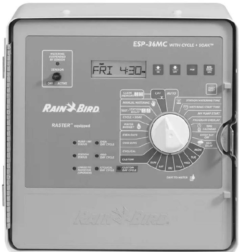
Looking at the Controller's Faceplate, continued
WATERING SUSPENDED BY SENSOR
This light is on when watering has been suspended by a sensor or the sensor jumper wire has been removed and the sensor switch is in the ACTIVE position.
SENSOR OFF/ACTIVE
If you want to activate the sensor, set the switch to ACTIVE. If you wish to override the sensor or there is no sensor connected to the controller, set the switch to OFF. When no sensor is connected, be certain that the jumper cable connecting the SENSOR terminals on the controller's circuit board is installed. If you set the SENSOR switch to ACTIVE without a sensor or jumper cable connected, the controller cannot operate the valves and no watering will occur.
▲/ON ON
Press to turn a setting on or to advance the setting in the display.
▼/OFF OFF
Press to turn a setting off or to decrease the setting in the display.
PGM PGM
Press to change the program displayed on the screen. When the PGM key is pressed, the indicator on the left side of the screen cycles through programs A, B, C and D.
MAN START/ADV. MAN. START ADV.
Press to advance to the next setting in the display or to manually start an operation.
FAULT RESET
Press to clear the fault reading from the display. Press this key after you have fixed the short circuit indicated by the diagnostic fault indicator in the display.
PUMP/MV STATUS
This light is on when the Master Valve 1 (MV1) circuit is enabled for the active station.
STATION STATUS
This light is on when a valve is active.
LINKED TO Maxicom ^2 (ESP-SAT and ESP-SITE-Satellite versions only)
This light is on when the STAND ALONE/MAXICOM switch is in the MAXICOM position and the controller is physically linked to the Maxicom ^2 system.
EVEN DAY CYCLE
This light is on when the controller's active program is set to water on even days of the month.
Looking at the Controller's Faceplate, continued
ODD DAY CYCLE
This light is on when the controller's active program is set to water on odd days of the month.
CYCLICAL DAY CYCLE
This light is on when the controller's active program is set to water in a cycle with a specified number of days.
CUSTOM DAY CYCLE
This light is on when the controller's active program is set to water on specific days of the week.
AUTO
Set the dial here to have the controller automatically run the programs you set.
STATION WATERING TIME
Set the dial here to set the length of an individual station's watering time.
WATERING START TIME
Set the dial here to set a program's watering start times. Eight start times are available for each program.
MV PUMP START
Set the dial here to enable or disable Master Valve 1 (MV1) for a particular station.
PROGRAM OVERLAP
Set the dial here to set programs to either stack or overlap. The default for all programs is stack.
TIME/CALENDAR
Set the dial here to set the time and date.
EVENT DAY OFF
Set the dial here to set optional day(s) off within the month.
RAIN DELAY
Set the dial here to delay watering for a specified number of days.
MON—SUN
Set the dial to the day of the week to turn that day off or on when setting a custom program cycle.
CUSTOM
Set the dial here to set a program cycle to water on specific days of the week.
CYCLICAL
Set the dial here to set a program cycle to water at specific intervals, such as every day, every second day, every third day, etc.
Looking at the Controller's Faceplate, continued
ODD DAYS
Set the dial here to set a program cycle that waters on odd days of the month.
EVEN DAYS
Set the dial here to set a program cycle that waters on even days of the month.
WATER BUDGET

Set the dial here to set the water budget percentage for a program. The default is 100%.
CYCLE + SOAK ^TM
Set the dial here to break a station's watering time into intervals to conserve water and prevent erosion.
TEST PROGRAM/STATION DELAY ON OFF
Set the dial here to set and start a test program cycle for all stations. Also, access the Station Delay feature by placing the dial in this position and holding down the ▲/ON and ▼/OFF keys simultaneously.
MANUAL WATERING
Set the dial here to water a station manually.
OFF/PROGRAM RESET ON MAN. START ADV.
Set the dial here to shut the controller and its valves down, such as during the winter months. Also reset all programs by placing the dial in this position and holding down the ▲/ON and MAN START/ADV keys for 10 seconds.
STAND ALONE/MAXICOM (located on the back of the front panel)
If you want your controller to function as a stand-alone unit, set this switch to STAND ALONE. If you want it to function as a satellite connected to the Maxicom ^2 system, set this switch to MAXICOM (ESP-SAT and ESP-SITE-Satellite versions only). If the controller is not connected to Maxicom ^2 , the position of this switch will have no effect on watering.
Rain Bird RASTER™ (Rapid Station Test Routine)
Introduction
Rain Bird's new RApid Station TEst Routine (RASTER ^4 ) lets you diagnose field wiring and solenoid problems quickly and easily.
The RASTER ^™ sends an electronic signal to each valve on the controller and then displays the valve's current operating condition in the easy-to-read digital display.
The RASTER ^™ tests and displays two different valve operating conditions:
- Open — Indicates an open circuit between the controller and the valve.
- Short — Indicates a short circuit between the controller and the valve.
The RASTER ^™ is a fast and easy way to make sure the controller's master valves and all station valves are operating properly.
The new RASTER™ feature is available on the Rain Bird ESP-MC, ESP-SAT, ESP-SITE-SAT and ESP-LX+ controllers.

Rain Bird RASTER™ (Rapid Station Test Routine), continued
RASTER™ Operation
Use the following procedure to perform the RASTER ^™ on the master valves and all other controller station valves.
Beginning the RASTER™
- Turn the Programming Dial to "OFF."
- Press and release the ▲/ON and ▼/OFF at the same time.
-
The display will look like the illustration below.
-
Press the "MAN START/ADV" to begin the RASTER™.
- The display shows "TEST IO" and the indicator lights on the front panel flash once as the RASTER ^TM confirms the proper operation of the controller's front panel lights.
NOTE: If the front panel is not connected to the output board or the controller is disconnected from the main power the display will show the message "NO OUT."
The RASTER™ then automatically begins the test on the controller's master valves and each station valve, beginning with the master valve 1.

Rain Bird RASTER™ (Rapid Station Test Routine), continued
-
The display shows "TEST M1" and "TEST M2" as the RASTER ^TM begins to check the operation of the master valves (an automatic valve installed on the mainline pipe upstream from the station valves).
-
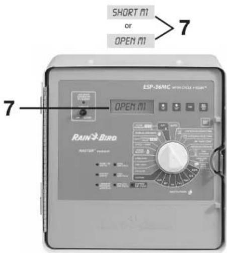
If the display shows "SHORT M1" or "OPEN M1" or "SHORT M2" or "OPEN M2" there may be a faulty circuit between the controller and the master valve. (On irrigation systems not equipped with a master valve, the "OPEN M1" or "OPEN M2" indicator is normal and requires no service.)
See "Troubleshooting Open and Shorted Valve Circuits" on page 11 for more information.

Rain Bird RASTER™ (Rapid Station Test Routine), continued
Station Valve Testing
After testing the master valves, the RASTER ^™ automatically tests each valve station, in numerical order, from lowest to highest.
- The display shows the valve's operating condition (OPEN or SHORT), followed by the station number (up to 40 stations, depending on controller model). This sample display indicates there is a short on valve station number 4.
- The RASTER™ displays the condition of each valve being tested for 10 seconds, and then moves to the next valve. You can press "MAN/START/ADV" (or any other magenta button) at any time to advance to the next station to be tested.
NOTE: Any controller station that does not have a valve connected to it will display an OPEN signal. For example, if you have a 12-station controller and only have stations 1 through 10 connected to valves, stations 11 and 12 will show "OPEN" on the RASTER™. This is normal and does not indicate any problem with the controller or system valves.
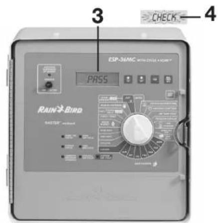
- If the master valves and all station valves pass the RASTER ^™ , the display flashes "PASS" for 10 seconds.
- If the RASTER™ detected a problem on the master valves or any station valve, the display flashes "CHECK" for three seconds and then displays the valve's problem condition (OPEN or SHORT) and station number or master valve.
Each problem valve will flash in the display for five seconds. Press "MAN START/ADV" at any time to display the next problem valve detected.
Any valve displaying "OPEN" or "SHORT" should be checked for field wiring or other circuit problems. See "Troubleshooting Open and Shorted Valve Circuits" on page 11 for more information.

Rain Bird RASTER™ (Rapid Station Test Routine), continued
- Turn the Programming Dial from "OFF" to "AUTO" (or any other dial position) at any time to exit RASTER ^TM mode.
- The controller returns to normal operation.
Troubleshooting Open and Shorted Valve Circuits
Open Circuits
When the RASTER ^™ shows an “OPEN” valve circuit, it indicates a complete break in the current flow between the controller and the valve.
NOTE: The RASTER™ will display an "OPEN" indicator if no valve solenoid is connected to the controller station. This is normal and the system does not need service.
These are the most common causes of open circuits:
• A malfunctioning valve solenoid
• Field wires that have been cut or pulled loose
- Loose wire connections on the controller's terminal strip or at the valve solenoid
- A damaged component on the controller's internal circuit board

Rain Bird RASTER™ (Rapid Station Test Routine), continued
Short Circuits
When the RASTER™ shows a “SHORT” test result, it indicates an unintended re-routing of the current flow somewhere between the controller and the valve.
These are some of the most common causes of short circuits:
• A shorted valve solenoid
- Nicked or "skinned" field wires
- Loose or corroded wire connections on the controller's terminal strip or at the valve solenoid
- A malfunctioning component on the controller's internal circuit board.
Troubleshooting Opens and Shorts
Use the following procedure to troubleshoot any valve identified as "OPEN" or "SHORT."
- Make sure the problem valve's station wires are securely connected on the controller's terminal strip.
- If the wires were securely connected, move the problem station's wires to a station that passed the RASTER ^TM and re-start the test.
- If the "OPEN" or "SHORT" moves to the new station, check the problem valve's solenoid and field wiring.
- If the "OPEN" or "SHORT" reoccurs on the original station, the controller's internal circuitry may need service.
Programming the Controller
Using the keys and dial on the controller's faceplate, you can set up the controller to operate automatically. You can also run the controller manually without making changes in the programs you have set.
This chapter will guide you through the use of the controller's keys and dial and will give you step-by-step instructions for setting up the four programs to suit your needs.
Preparing to Program the Controller
The controller comes from the factory without a pre-set default program. The following table presents a summary of the controller's default program settings:
| Custom Cycle | ||||||||||
| Progr. | Station # | Water Time | Start Time | 1 (MON) | 2 (TUES) | 3 (WED) | 4 (THU) | 5 (FRI) | 6 (SAT) | 7 (SUN) |
| A All 0 | Min 8:00A | on on on on | on on on | |||||||
Before you begin programming, it is a good idea to chart your watering schedule on a piece of paper, taking into account the schedule for all stations and how often you want to repeat the schedule. A blank schedule is provided for you on pages 32-33.
Programming the Controller, continued
Setting the Time and Date
The first step in programming the controller is setting the controller's internal clock and calendar. To do so,
- Rotate the dial to TIME/CALENDAR.

The hour digits in the display flash, indicating that they are ready to be set.

- Use the arrow keys to set the hour.
If you have a 60 Hz model, as you pass 12:00 the am/pm designation changes.
Note: The 60 Hz model displays time in the 12-hour am/pm mode. The 50 Hz model displays time in the 24-hour mode.
- Press MAN START/ADV.
The minute digits flash, indicating that they are ready to be set.
-
Use the arrow keys to set the minutes to the current time.
-
Press MAN START/ADV.
A new display appears with the day, month and year. The month flashes, indicating that it is ready to be set.

- Use the arrow keys and the MAN START/ADV
key to set the month, day and year the same way you set the hour and minutes.
- Press MAN START/ADV 📄vice to return to the time of day display.
The hour continues to flash as long as the dial is left at TIME/CALENDAR
- Return the dial to AUTO.
The display shows the day of the week and time of day.

Programming the Controller, continued
Setting up a Program
There are four independent programs available with the controller: A, B, C, and D. You can set each program to operate according to your specifications. When you set up a program, you:
- select the program
- choose a cycle setting for the program
- assign stations and set the station's watering durations and start times
It is easier to select a program and program it completely. Jumping from program to program can be confusing.
Step 1: Selecting a Program
To select the program you want to set up,
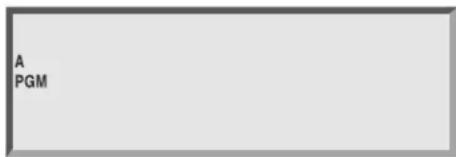
Press PGM cycle through the available programs.
The program indicator on the far left side of the display changes.
Step 2: Selecting the Cycle
Each program can operate in one of four cycle modes:
- CUSTOM waters on the days of the week you select.
- CYCLICAL waters according to a cycle with a specified number of days.
- ODD waters only on odd days of the month.
• EVEN waters only on even days of the month.
Note: All programs default to the custom cycle.
To set a custom cycle,
- Rotate the dial to CUSTOM.
The display shows the program and CUSTOM.

The display shows USED if the program is active and using a different cycle mode. If desired, you can override the previous setting.
- If the program you want is not displayed, press PGM until it is.
- Press ON.
The display shows CUSTOM and the custom light on the faceplate illuminates.
- Rotate the dial to the first day of the week and use the ON and OFF keys to turn the day on or off.
The display shows the day and the ON/OFF setting.

- Repeat step 4 for all the days of the week you want to change.
- Return the dial to AUTO.
The controller returns to the time of day display and waters on the days you have specified.
Programming the Controller, continued
To set a cyclical cycle,
- If the program you want is not displayed, press PGM until it is.
- Rotate the dial to CYCLICAL.
The display shows the number of days remaining and the number of days in the cycle. The number of days in the cycle is flashing, indicating that it is ready to be set. If it is not flashing, press MAN START/ADV until the number of days in the cycle is flashing.
The display shows USED if the program is active and using a different cycle mode. If this is the case, you can override the previous setting.
- Press ON.
The cyclical display appears and the cyclical light on the faceplate illuminates.
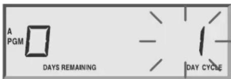
- Use the arrow keys to set the number of days in the cycle.
For example, if you set a 3-day cycle, the controller skips two days and waters on the third.
- Press MAN START/ADV toggle to the left side of the display.
The number of days remaining in the cycle flashes, indicating that it is ready to be set.
- Use the arrow keys to set the number of days remaining before the next watering day. This tells the controller where today is in the cycle you have just set. For example, if DAYS REMAINING is set to "0," watering will occur today. If DAYS REMAINING is set to "1," watering will occur tomorrow.
- Return the dial to AUTO.
The controller returns to the time of day display and waters on the days you have specified.
To set an odd or even cycle,
- If the program you want is not displayed, press PGM until it is.
- Rotate the dial to ODD DAYS or EVEN DAYS. The display shows the program and ODD or EVEN.
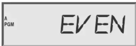
The display shows USED if the program is active and using a different cycle mode. If this is the case, you can override the previous setting.
- Press ON.
The display shows either ODD or EVEN and the corresponding light on the faceplate illuminates.
- Return the dial to AUTO.
The controller returns to the time of day display and waters on the days you have specified.
Note: The 31st day of the month defaults to ON, so if you do not want to water on the 31st, you must set that day to OFF. See page 21 for more information
Programming the Controller, continued
Step 3: Setting the Length of a Station's Watering Time
Within the program you are setting, you can set the length of a station's watering time from 0 minutes to 12 hours. Set the time in one-minute increments for up to two hours; set it in 10-minute increments from two hours to 12 hours.
To set the length of a station's watering time,
-
If the program you want is not displayed, press PGM until it is.
-
Rotate the dial to STATION WATERING TIME. The display shows the program, the station number and the length of watering time. The station number is flashing, indicating that it is ready to be set.
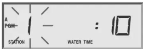
If the station is included in any other program, the controller will let you know by replacing the length of watering time with USED.
-
Use the arrow keys to display the station number you wish to set.
-
Press MAN START/ADV toggle to the right side of the display. The length of watering time flashes, indicating that it is ready to be set.
-
Use the arrow keys to set the length of time. If USED is displayed, you can still set the length of time. (You can include the same station in different programs and give that station different lengths of watering time.)
- Return the dial to AUTO. The controller returns to the time of day display.
Step 4: Setting Watering Start Times
For each program, you may assign up to eight start times per day, available on the quarter hour.
To assign start times,
- If the program you want is not displayed, press PGM until it is.
- Rotate the dial to WATERING START TIME.
The display shows the program, the number of the start time and the start time. The number of the start time is flashing, indicating that it is ready to be set.

- Use the arrow keys to select one of the eight start times.
- Press MAN START/ADV toggle to the right side of the display. The start time flashes, indicating that it is ready to be set.
Programming the Controller, continued
- Use the arrow keys to select a start time. Start times are available in 15 minute intervals, with an OFF setting available between the 11:45 pm and 12:00 am options on the 60 Hz model (and between 23:45 and 24:00 on the 50 Hz model).
Note: Start times are displayed in chronological order. If a start time is deleted by setting it to OFF, all later start times are automatically moved down one start time number. When a start time is added to any start time number, the controller automatically reorganizes the times so that times appear in chronological order. This reorganization only occurs after the dial has been moved off the WATERING START TIMES position.
- If you want to set additional start times, press MAN START/ADV toggle back to the left side of the display and the next available start time number. Set the next start time in the same fashion as the first.
- Return the dial to AUTO.
The controller returns to the time of day display.
Step 5: Setting Programs to Stack or Overlap
You can set a program to stack (run one at a time) or overlap (run simultaneously). The controller can run up to nine valves simultaneously. The default setting is to stack all programs.
To set programs to stack or overlap,
- Rotate the dial to PROGRAM OVERLAP.
The display shows the program and STACK or OVERLAP.
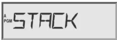
- If the program you want is not displayed, press PGM until it is.
- Use the arrow keys to set the program to either STACK or OVERLAP.
- Return the dial to AUTO.
The controller returns to the time of day display.
Step 6: Setting the MV/PUMP Start
The controller has two master valve terminals on its circuit board. MV2 (master valve 2) is enabled when any station operates. MV1 (master valve 1) can be enabled or disabled for each individual station.
To set MV1 for a station,
- Rotate the dial to MV PUMP START.
The display shows the station number and MV ON or OFF. The station number is flashing, indicating that it is ready to be set.

- Use the arrow keys to select the station number.
- Press MAN START/ADV toggle to the right side of the display. The ON or OFF flashes, indicating that it is ready to be set.
- Press either the ON or OFF key.
- If you want to set another station, press MAN START/ADV toggle back to the left side of the display to continue setting stations.
- When you are finished setting stations, return the dial to AUTO.
The controller returns to the time of day display.
Programming the Controller, continued
Setting Rain Delay
The controller allows you to delay watering for a specified number of days up to a maximum of 99 days. The Rain Delay setting affects all programs.
To set a Rain Delay,
- Rotate the dial to RAIN DELAY.
The display shows RAIN DELAY and the number of days until watering will resume.

- Use the arrow keys to set the number of days to begin watering.
- Return the dial to AUTO.
The controller returns to the time of day display and will delay watering for the number of days you have specified.
Note: To cancel a Rain Delay, reset the number of days to 0.
Setting Cycle + Soak™
The Cycle + Soak ^™ feature is designed to conserve water that might puddle in tight soils, such as clay, or end up as runoff on slopes. Cycle + Soak ^™ lets you break up the total watering time of a station into shorter cycles with a soak time between cycles. You set the maximum watering time length and the minimum soak time. This setting affects all programs in which the station is included.
For example, if you want to water a station for a 20 minutes, but runoff occurs after five minutes, you can set the station for five-minute maximum cycles and a minimum of 25 minutes between cycles. While the station is in soak mode, the controller operates other stations in the program.
Note: If there is nothing left for the controller to do but wait until a soak time elapses, the display shows SK.
Note: The test program does not respond to Cycle + Soak ^™ settings.
To set Cycle + Soak ^™ ,
- Rotate the dial to CYCLE + SOAK ^TM .
The display shows the station number, the maximum length of time to water and the minimum soak time. The station number flashes, indicating that it is ready to be set.

Programming the Controller, continued
- Use the arrow keys to select the station.
- Press MAN START/ADV.
The length of time to water flashes, indicating that it is ready to be set.
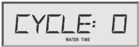
- Use the arrow keys to set the maximum watering time from 1 to 99 minutes.
- Press MAN START/ADV
The length of time to soak flashes, indicating that it is ready to be set.

- Use the arrow keys to set the minimum soak time from 1 to 99 minutes.
- If you want to set Cycle + Soak ^TM for another station, press MAN START/ADV again.
- When you have finished setting Cycle + Soak ^TM , return the dial to AUTO.
The controller returns to the time of day display.
Setting the Water Budget
The water budget feature allows you to increase or decrease a program's watering time in increments of 1% without having to reset the timing for each station in the program. You can set the budget for 0% to 300% . You can use the 0% setting to shut a program down temporarily.
To set the water budget,
- Rotate the dial to WATER BUDGET.
The display shows the program and the water budget percentage.

- Press PGM until the program you want is displayed.
- Use the arrow keys to set the percentage.
- Return the dial to AUTO.
The controller returns to the time of day display. The default percentage for all programs is 100%. When the water budget for a program is set to other than 100%, WATER BUDGET will show in the display whenever that program is selected.
Note: The maximum watering time with WATER BUDGET is 16 hours.
Programming the Controller, continued
Setting Event Day Off
The Event Day Off feature allows you to omit temporarily a calendar day or days from the watering cycle. After a calendar day passes, that day returns to the default setting. The default for all days is ON. If the 31st is set to OFF, it remains off until it is set to ON. This is to accommodate odd day watering cycles which do not allow watering on the 31st.
To set a day off,
- Rotate the dial to EVENT DAY OFF.
The display shows the day of the month on the left and the ON or OFF setting on the right. The day of the month is flashing, indicating that it is ready to be set.

- Use the arrow keys to set the day of the month you wish to change.
- Press MAN START/ADV toggle to the right side of the display.
The ON/OFF setting flashes, indicating that it is ready to be set.
- If you are setting the day to on, press ON; if you are setting the day to off, press OFF.
- Return the dial to AUTO.
When a day off arrives, the display shows NON (for non-watering day) and the controller does not allow watering.
Setting a Delay between Stations
The controller allows you to set a delay between stations for each program. The delay can be from 0 seconds (default) to nine hours.
To set a delay between stations,
- Rotate the dial to TEST/STATION DELAY


- Press both ▲/ON and ▼/OFF keys simultaneously.
The display shows DELAY.

- Press the PGM key to select the program to which the delay is to be applied.
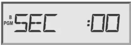
- Use the ▲/ON and the ▼/OFF keys to select the delay time you desire. The delay time can be set in:
• one-second increments, between one second and five minutes
• one-minute increments, between five minutes and nine hours
Programming the Controller, continued
Clearing All Programs
The controller allows you to clear all programs. This function erases all settings and programs previously set, allowing you to completely reprogram the controller.
To clear all programs from the controller,
- Rotate the dial to OFF.
- Hold down the ▲/ON and MAN START/ADV
MAH. START ADV. keys for 10 seconds.
The display cycles through various items on the screen as the controller clears the registers.
When the screen returns to Thu 12:00 am, all programs have been cleared and you may begin programming the controller.
Operating the Controller
Once you have programmed the controller, operating it is easy. You may choose to operate it completely automatically or to operate it manually from time to time. When you operate the controller manually, you do not disturb any of the programmed instructions.
Operating the Controller, continued
Operating Automatically
To operate the controller automatically,
Rotate the dial to AUTO.
The controller runs each of the programs as you have specified.
Note: The controller will operate automatically in any position except for OFF. However, there will be no display of the day, time or program status. When the controller is in the OFF position, the controller will not operate.
Operating Manually
There are a number of functions you can perform manually. Each one is described in this section.
Operating a Program or Programs Manually
You can select, start and manually advance programs for semi-automatic operation.
To do so,
- Rotate the dial to AUTO.
The display shows the day of the week and the time of day.

- Press PGM until the program you wish to operate is displayed.
- Press MAN START/ADV start the selected program.
- If you want to operate more than one program, press PGM to select another program and press MAN START/ADV again.
The second program runs when the first is complete. You can stack all four programs in this way.
Operating the Controller, continued
Operating a Station or Stations Manually
You can initiate one-time operation of a single station or a combination of stations. If you run more than one station, they will run in the order in which they were selected.
To operate one station or multiple stations,
- Rotate the dial to MANUAL WATERING.
The display shows the program, the station number and any watering time remaining on that station.

- Press PGM until the program using the desired station is displayed.
- Use the arrow keys to select the station you want to operate.
- Press MAN START/ADV → start the selected station.
- If you want to operate more than one station, repeat steps 2 through 4.
- Return the dial to AUTO.
The stations operate in the sequence they were selected. After the stations finish watering, the controller returns to the automatic mode.
Note: If you are operating a station manually, you cannot change the amount of time the station will water. The controller will water the programmed amount.
Using the Test Program
This program allows you to run a test cycle for all the stations on a particular program. You may select how long the test will last.
To set and then start a test program,
- Rotate the dial to OFF for 3 seconds, to cancel any pending work. Otherwise the test program will be executed after the automatic mode work finishes.
- Rotate the dial to TEST/STATION DELAY


The display shows the program, TEST and the length of time to test.
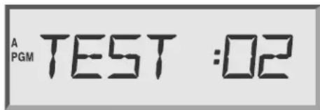
- Press PGM until the program you want to test is displayed.
- Use the arrow keys to set the length of time to test each station, from one to 99 minutes.
- Press MAN START/ADV to start the test.
- If you want to add other programs to the test, with the dial set to TEST/STATION DELAY ON OFF press PGM to select the program.
Then press MAN START/ADV stack the new program after the first one. You can stack four programs.
Note: To cancel the test on all programs, rotate the dial to OFF.
Operating the controller, continued
Using the Sensor Option
The controller allows you to connect a sensor that can disable watering. When a sensor is connected to the controller and it suspends watering, the sensor light on the front panel illuminates.
To enable the sensor,
Set the sensor switch to ACTIVE.
The controller operates as usual until the sensor suspends watering and the SUSPENDED BY SENSOR light is on.
Note: When no sensor is attached, the jumper cable supplied with each controller must be in place, connecting the SENSOR terminals on the controller circuit board. If you set the SENSOR switch to ACTIVE with neither a sensor nor the jumper cable connected, the controller cannot operate the valves and no watering will occur.
Fuse Detection
The controller display will show FUSE if a fuse is missing or blown.
Using the Diagnostic Circuit Breaker
The controller is equipped with a circuit overload protection system. This system causes the controller to skip over a station that has an electrical short circuit, rather than blow a fuse which would shut down the entire system. When the controller tries to start a station that has a short circuit, the electronic circuit breaker senses the short circuit and skips that station. The controller skips to the next station, but flashes the skipped station number and FAULT in the display.
Once you have corrected the problem, push the FAULT RESET key to clear the flashing fault indicator.
Note: The diagnostic circuit breaker allows detection on all stations, as well as the master valve.
Replacing the Battery
- Open the cabinet door.
- Release the latch by sliding it to the left and swing the panel open.
- Open the battery cover on the back of the faceplate. Remove the 9-volt battery.
- Install a new rechargeable 9-volt battery and close the cover.
- Close the faceplate.
IMPORTANT! Use only rechargeable batteries in your controller. Non-rechargeable batteries could damage the controller or be a fire hazard.
Troubleshooting
The following pages contain possible problems you may encounter and some solutions. Before calling Rain Bird, check this list. If you cannot solve the problem yourself, call our Technical Service Hotline at 1-800-247-3782 (1-800-BIRD-SVC) and we will be glad to help you.
General Troubleshooting
Problem The display is flashing.
Solution There may be a power outage. Or, check the battery; it may be dead or improperly connected.
Problem Parts are missing or damaged.
Solutions Try one of the following solutions:
- Damage occurred during shipping. Return the controller.
- Lightning has damaged the controller. If the controller is installed, replace the piece that is damaged (front panel, output board, transformer, cabinet, etc.).
Problem The controller is dead; the display is blank and there is no station output.
Solutions Try one of the following solutions:
- There is no power to the controller. Check that the main power source is on.
- The transformer is not connected properly. Check that the 5-wire cable from the transformer is properly connected to J7 on the controller output board.
- The transformer is bad. Check if there are 24 V AC between the "24VAC" and "COM" terminals.
Troubleshooting, continued
Problem The display and programming operate normally, but stations and master valves will not activate.
Solutions Try one of the following solutions:
- Watering has been suspended by a sensor. Check if the sensor LED on the front panel is lit. If so, then watering has been suspended by your sensor. If watering is required immediately, move the Sensor Bypass switch to OFF.
- No sensor is installed. The Sensor Bypass switch is in the ACTIVE position and the jumper wire across the sensor inputs has been removed. Place the Sensor Bypass switch in the OFF position and add a wire jumper across the two Sensor terminals on the output board.
- The sensor is malfunctioning. Remove the sensor and place the Sensor Bypass switch in the OFF position and attempt to activate the valves. If this works, place the Sensor Bypass switch in the ACTIVE position and attempt to activate the valves. If the display indicates that valves are active, but they are not coming on and the WATERING SUSPENDED BY SENSOR LED is on, then the sensor input is not working properly. Repair or replace the sensor.
- The main fuse is blown. If the word FUSE appears in the display, replace the 2.5 A fuse located on the output board.
Problem The controller will not execute the programmed schedule.
Solutions Try one of the following solutions:
- The controller dial is in the OFF position. Place the dial in the AUTO position.
- The Rain Delay feature has been activated. When the Rain Delay feature is active, the words RAIN DELAY appear in the upper left corner of the controller display. There is also a number indicating the number of days remaining before the controller will start running its schedule. To eliminate the Rain Delay, turn the dial to the RAIN DELAY position and use the ▼/Off OFF key to set the number of days remaining to zero.
- There is no start time programmed for one or more programs. Place the dial in the WATERING START TIMES position and select the desired program with the PGM key. Check to see if an appropriate start time is entered for each program.
- Today has been programmed as a Non-Watering Day. If this is a Non-Watering Day, the word NON will appear in the display. If you would like to water today, move the dial to the EVENT DAY OFF position, select the appropriate day of the month and set it to ON.
Troubleshooting, continued
- The fuse is blown and the battery is still charged. Replace the fuse.
- There is no power to the controller and the battery is still charged. Check the input power source.
Problem A station will not activate.
Solutions Try one of the following solutions:
- No run time has been programmed. Place the dial in the STATION WATERING TIME position, select the desired program, select the station you would like to water and set the desired watering time.
- There is no start time for the program containing the desired station. Place the dial in the WATERING START TIMES position and select the desired program with the PGMkey. Check to see if the appropriate start times are entered.
- There is a short circuit in the valve wiring or solenoid. In this case, the message FAULT XX will flash in the display. Check station wiring and the solenoid. After the short circuit is repaired, press the FAULT RESET key on the controller front panel.
- The MOV or Triac failed. Remove the output board and take it to your local Rain Bird distributor for repair or warranty replacement.
Problem The controller activates stations at unexpected times.
Solutions Try one of the following solutions:
- The MAN START/ADV. KEY is stuck, causing a program to start unexpectedly. Press the MAN START/ADV. Key and make sure that it releases when you remove your finger.
- Additional program times have been entered accidentally. Check the program start times for all four programs. Delete any that should not be there.
- The controller's panel is temporally scrambled due to power fluctuations and surges. Shut off the power to the controller by removing the main power AND removing the battery. Let the controller sit for about five minutes, then restore the power to the controller. If this does not work, reset the controller by holding down the ▲/ON. ⬆ and MAN START/ADV. MAX START ADV. keys until words in the display begin to change. When the display shows “12:00,” reprogram the controller.
- Stations may be wired to the wrong terminal locations. Check which station wires lead to which zone by connecting the wiring (one station at a time) to the 24 V AC terminal on the controller. When you confirm that the wiring turns on the desired zone, reconnect the wires to the corresponding station.
Troubleshooting, continued
Problem The actual watering time is different from the time programmed.
The Water Budget feature is active. Check the Water Budget for the program containing the station(s) exhibiting the problem.
Problem The display is blank, partial or displays something which is not readable.
Solution A surge caused the display to scramble. Turn off the main power to the controller, remove the rechargeable battery and let the controller sit for about five minutes. Reconnect the power and reattach the rechargeable battery. If there has been no permanent damage, the controller will operate normally.
Maxicom ^2 -specific Troubleshooting
Problem The controller is not operating under Maxicom ^2 control.
Solution Try one of the following solutions:
- Check the MAXICOM...STAND ALONE switch on the back of the controller front panel. It should be in the MAXICOM position.
- Contact the Rain Bird Technical Service Hotline for assistance.
Problem The controller does not water, but the Maxicom ^2 system reports normal operation.
Solution The SENSOR switch is in the incorrect position. Move the SENSOR switch to OFF.
Problem A Maxicom ^2 feature appears to operate correctly at the computer, but will not function when it is sent to the controller.
Solution Verify that the channel assignment on the controller matches the CCU channel assignment. The controller has a maximum of 28 channel assignments, depending on the type of CCU the controller is connected to. ESP-SITE-Satellite controllers must be set to channel 1.
Appendix A: Scheduling Chart
Before you begin programming, it is a good idea to chart your watering schedule, taking into account the schedule for all stations and how often you want to repeat the schedule. For specific programming instructions, see page 13. A sample schedule appears below. A blank schedule that you can copy and fill in appears on the following pages.

PROGRAMMING CHART
For ESP-MC Controllers
| Program A | Program B | Program C | Program D | ||||
| SMTWTF S□ _day cycle□ even□ odd | SMTWTF S□3day cycle□ even□ odd | SMTWTF S□ _day cycle□ even#odd | SMTWTF S□ _day cycle#even□ odd | ||||
| 1 | 8:00 am / pm | 1 | 8:45 am / pm | 1 | 7:00 am / pm | 1 | 9:00 am / pm |
| 2 | 7:00 am / pm | 2 | 6:00 am / pm | 2 | 9:00 am / pm | 2 | 3:00 am / pm |
| 3 | am / pm | 3 | am / pm | 3 | 11:00 am / pm | 3 | am / pm |
| 4 | am / pm | 4 | am / pm | 4 | 2:00 am / pm | 4 | am / pm |
| 5 | am / pm | 5 | am / pm | 5 | 4:00 am / pm | 5 | am / pm |
| 6 | am / pm | 6 | am / pm | 6 | 8:00 am / pm | 6 | am / pm |
| 7 | am / pm | 7 | am / pm | 7 | 10:00 am / pm | 7 | am / pm |
| 8 | am / pm | 8 | am / pm | 8 | 11:45 am / pm | 8 | am / pm |
| Water Budget Station Delay | 100% | 100% | 120% | 43% | |||
| MV/Pump Relay 1* | Run Time Run Time Run Time Run Time Cycle Soak | ||||||
| on | 10 | ||||||
| on | 20 | ||||||
| on | 20 | ||||||
| on | 5 | ||||||
| on | 10 | ||||||
| on | 10 | ||||||
| on | 20 | ||||||
| on | 20 | ||||||
| on | 20 | ||||||
| on | |||||||
| on | |||||||
Rain Bird Technical Services: 800-247-3782
| Station Description | MV/Pump Relay 1 * | Run Time Run Time Run Time Run Time Cycle Soak | |||||||
| 1 | Front turf #1 | on | 10 | ||||||
| 2 | Front turf #2 | on | 20 | ||||||
| 3 | Front turf #3 | on | 20 | ||||||
| 4 | Front turf #4 | on | 5 | ||||||
| 5 | Side shrubs | 4 | 10 | on | 10 | ||||
| 6 | Back shrubs | on | 10 | ||||||
| 7 | Front shrubs | on | 20 | ||||||
| 8 | Back turf #1 | on | 20 | ||||||
| 9 | Back turf #2 | on | 20 | ||||||
| 10 | on | ||||||||
| 11 | on | ||||||||
| 12 | on | ||||||||
| on | |||||||||

PROGRAMMING CHART
For ESP-MC Controllers

Watering Days

Program Start Times
Water Budget Station Delay
| Program A | Program B | Program C | Program D | ||||
| SMTWTF S | SMTWTF S | SMTWTF S | SMTWTF S | ||||
| □_day cycle | □_day cycle | □_day cycle | □_day cycle | ||||
| □even | □even | □even | □even | ||||
| □odd | □odd | □odd | □odd | ||||
| 1 | am/pm | 1 | am/pm | 1 | am/pm | 1 | am/pm |
| 2 | am/pm | 2 | am/pm | 2 | am/pm | 2 | am/pm |
| 3 | am/pm | 3 | am/pm | 3 | am/pm | 3 | am/pm |
| 4 | am/pm | 4 | am/pm | 4 | am/pm | 4 | am/pm |
| 5 | am/pm | 5 | am/pm | 5 | am/pm | 5 | am/pm |
| 6 | am/pm | 6 | am/pm | 6 | am/pm | 6 | am/pm |
| 7 | am/pm | 7 | am/pm | 7 | am/pm | 7 | am/pm |
| 8 | am/pm | 8 | am/pm | 8 | am/pm | 8 | am/pm |
Rain Bird Technical Services: 800-247-3782
| Station Description | MV/Pump Relay 1 * | Run Time Run Time Run Time Run Time Cycle Soak | ||||||
| 1 | ☐ on | |||||||
| 2 | ☐ on | |||||||
| 3 | ☐ on | |||||||
| 4 | ☐ on | |||||||
| 5 | ☐ on | |||||||
| 6 | ☐ on | |||||||
| 7 | ☐ on | |||||||
| 8 | ☐ on | |||||||
| 9 | ☐ on | |||||||
| 10 | ☐ on | |||||||
| 11 | ☐ on | |||||||
| 12 | ☐ on | |||||||
| 13 | ☐ on | |||||||
| 14 | ☐ on | |||||||
| 15 | ☐ on | |||||||
| 16 | ☐ on | |||||||
| 17 | ☐ on | |||||||
| 18 | ☐ on | |||||||
| 19 | ☐ on | |||||||
| 20 | ☐ on | |||||||
| 21 | ☐ on | |||||||
| 22 | ☐ on | |||||||
| 23 | ☐ on | |||||||
| 24 | ☐ on | |||||||
| 25 | ☐ on | |||||||
| 26 | ☐ on | |||||||
| 27 | ☐ on | |||||||
| 28 | ☐ on | |||||||
| 29 | ☐ on | |||||||
| 30 | ☐ on | |||||||
| 31 | ☐ on | |||||||
| 32 | ☐ on | |||||||
| 33 | ☐ on | |||||||
| 34 | ☐ on | |||||||
| 35 | ☐ on | |||||||
| 36 | ☐ on | |||||||
| 37 | ☐ on | |||||||
| 38 | ☐ on | |||||||
| 39 | ☐ on | |||||||
| 40 | ☐ on | |||||||
| Days Off: | ||||||||
| Notes: | ||||||||
* MV/Pump Relay #2 is always on whenever any station operates.
Appendix B: Maxicom ^2 Central Control System Overview
ESP-MC and ESP-SAT Controllers
The controller is one part of Rain Bird's Maxicom ^2 Central Control System. (See the illustration on the next page.) The satellite controllers receive commands from the Cluster Control Unit (CCU) and operate stations according to schedules programmed at the central computer.
The Maxicom ^2 Central Control System for ESP-MC and ESP-SAT controllers chiefly consists of seven parts:
- Central Computer uses the Maxicom ^2 software program to control the entire irrigation system
- Computer Data Path transfers information from the central computer to the CCU by phone communication or by radio/direct communication
- Cluster Control Unit operates field devices by executing commands received from the central computer
- Satellite Data Path transfers information from the cluster control unit to the field devices by a two-wire path (TW) or by MAXILink radio communication
- Field Devices includes either satellite controllers or decoders: Satellite controllers — send a 24 VAC power signal to each station Decoders — control and monitor system functions
- Stations consist of irrigation valves, sensors or switch-operated devices
- Weather Station interprets weather conditions and sends information to the central computer
Appendix B, continued
Phone (PH) Version Radio/Direct Version

flowchart
```mermaid
graph TD
    A["Central Computer"] --> B["Cellular Telephone"]
    A --> C["Phone"]
    A --> D["CCU at site"]
    A --> E["Hardware/Short-haul Modem"]
    A --> F["Point-to-point Radio Link"]
    A --> G["Trunk Radio"]
    A --> H["Satellite Controller"]
    A --> I["Satellite Controller"]
    J["Weather Station"] --> K["Sensor"]
    J --> L[Switch or Valve Valve Valve Valve Valve Valve Valve Valve Valve Valve Valve Valve Valve Valve Valve Valve Valve Valve Valve Valve Valve Valve Valve Valve Valve Valve Valve Valve Valve Valve Valve Valve Valve Valve Valve Valve Valve Valve Valve Valve Valve Valve Valve Valve Valve Valve Valve Valve Valve Valve Valve Valve Valve Valve Valve Valve Valve Valve Valve Valve Valve Valve Valve Valve Valve Valve Valve Valve Valve Valve Valve Valve Valve Valve Valve Valve Valve Valve Valve Valve Valve Valve Valve Valve Valve Valve Valve Valve Valve Valve Valve Valve Valve Valve Valve Valve Valve Valve Valve Valve valve valve valve valve valve valve valve valve valve valve valve valve valve valve valve valve valve valve valve valve valve valve valve valve valve valve valve valve valve valve valve valve valve valve valve valve valve valve valve valve valve valve valve valve valve valve valve valve valve valve valve valve valve valve valve valve valve valve valve valve valve valve valve valve valve valve valve valve valve valve valve valve valve valve valve valve valve valve valve valve valve valve valve valve valve valve valve valve valve valve valve valve valve valve valve valve valve valve valve valve valves with sensor or switch or valves with valves with valves.    %% Note: The diagram uses standard hierarchical labels to identify components of the network. Text labels on the diagram are in English, but the structure is purely structural and not explicitly labeled. The diagram contains multiple hierarchical nodes and connections, possibly representing a system architecture or network topology.
Appendix B, continued
ESP-SITE-Satellite Controller
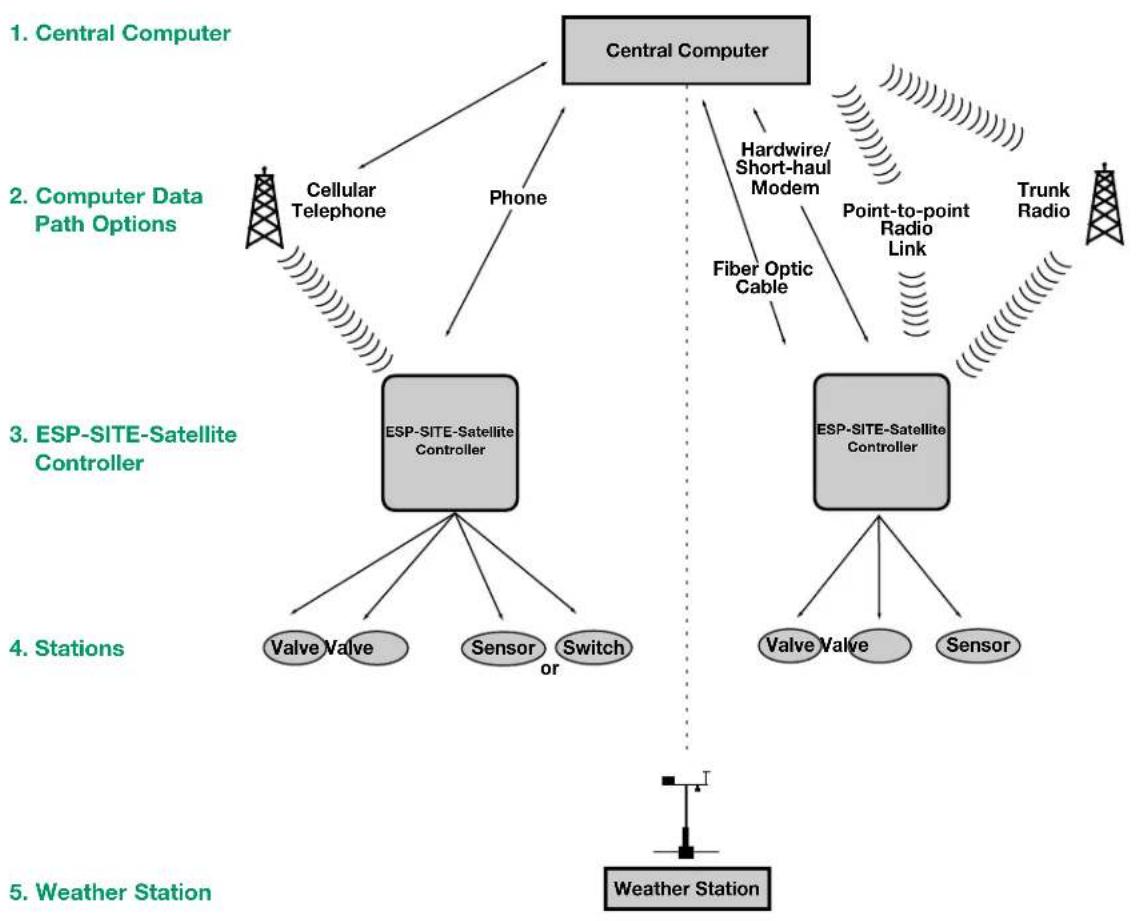
The controller is one part of Rain Bird's Maxicom ^2 Central Control System. (See the illustration on the next page). The satellite controllers receive commands from the central computer and operate stations according to schedules programmed at the central computer.
The Maxicom ^2 Central Control System for ESP-SITE-Satellite controllers chiefly consists of five parts:
- Central Computer uses the Maxicom ^2 software program to control the entire irrigation system
- Computer Data Path transfers information from the central computer to the ESP-SITE-Satellite by phone communication or by radio/direct communication
- Controller operates stations by executing commands received from the central computer
- Stations consist of irrigation valves, sensors or switch-operated devices
- Weather Station interprets weather conditions and sends information to the central computer
Appendix B, continued
Phone (PH) Version Radio/Direct Version
flowchart
graph TD
    A["Central Computer"] --> B["Cellular Telephone"]
    A --> C["Phone"]
    A --> D["ESP-SITE-Satellite Controller"]
    A --> E["ESP-SITE-Satellite Controller"]
    B --> F["Valve Valve"]
    B --> G["Sensor"]
    B --> H["Switch or"]
    E --> I["Valve Valve"]
    E --> J["Sensor"]
    E --> K["Trunk Radio"]
    D --> L["Fiber Optic Cable"]
    D --> M["Hardwire/Short-haul Modem"]
    M --> N["Point-to-point Radio Link"]
    M --> O["Trunk Radio"]
    style A fill:#ccc,stroke:#333
    style B fill:#ccc,stroke:#333
    style D fill:#ccc,stroke:#333
    style E fill:#ccc,stroke:#333
    style F fill:#ccc,stroke:#333
    style G fill:#ccc,stroke:#333
    style H fill:#ccc,stroke:#333
    style I fill:#ccc,stroke:#333
    style J fill:#ccc,stroke:#333
    style K fill:#ccc,stroke:#333
    style L fill:#ccc,stroke:#333
    style M fill:#ccc,stroke:#333
    style N fill:#ccc,stroke:#333
    style O fill:#ccc,stroke:#333
    style P fill:#ccc,stroke:#333
    style Q fill:#ccc,stroke:#333
    style R fill:#ccc,stroke:#333
    style S fill:#ccc,stroke:#333
    style T fill:#ccc,stroke:#333
    style U fill:#ccc,stroke:#333
    style V fill:#ccc,stroke:#333
    style W fill:#ccc,stroke:#333
    style X fill:#ccc,stroke:#333
    style Y fill:#ccc,stroke:#333
    style Z fill:#ccc,stroke:#333
    style AA fill:#ccc,stroke:#333
    style AB fill:#ccc,stroke:#333
    style AC fill:#ccc,stroke:#333
    style AD fill:#ccc,stroke:#333
    style AE fill:#ccc,stroke:#333
    style AF fill:#ccc,stroke:#333
    style AG fill:#ccc,stroke:#333
    style AH fill:#ccc,stroke:#333
    style AI fill:#ccc,stroke:#333
    style AJ fill:#ccc,stroke:#333
    style AK fill:#ccc,stroke:#333
    style AL fill:#ccc,stroke:#333
    style AM fill:#ccc,stroke:#333
    style AN fill:#ccc,stroke:#333
    style AO fill:#ccc,stroke:#333
    style AP fill:#ccc,stroke:#333
    style AQ fill:#ccc,stroke:#333
    style AR fill:#ccc,stroke:#333
    style AS fill:#ccc,stroke:#333
    style AT fill:#ccc,stroke:#333
    style AU fill:#ccc,stroke:#333
    style AV fill:#ccc,stroke:#333
    style AW fill:#ccc,stroke:#333
Appendix C: Setting the Channel Number
If you are using an ESP-SAT or ESP-SITE-Satellite controller, each Maxicom ^2 satellite on a CCU must have a channel number for successful communication.
To set the channel number,
- Turn the dial on the controller's faceplate to the TIME/CALENDAR position.
- Press the MAN. START/ADV. 📄 on the faceplate until the number "1" and the word "CHAN" appear in the display.

- Use the ▲/ON ▲d ▼/OFF keys to select the channel number you desire.
Note: If the satellite is a 32- or 40-station model, the controller will operate the first 24 stations on the channel number you select and the remaining stations on the next number in the sequence. For example, if you select channel 5 on a 40-station satellite, stations 1-24 will operate on channel 5, and stations 25-40 will operate on channel 6.
Warning! Never select channel 28 (on a CCU-28) or channel 6 (on a CCU-6) for a 32- or 40-station satellite. There are no channels higher than 28 for the CCU-28 and no channels higher than 6 for the CCU-6. Stations will not operate when assigned to channels higher than 28 (CCU-28) or 6 (CCU-6).
Note: ESP-SITE Satellite controllers must be set to channel 1.
Appendix D: ESP-MC Controller Spare Parts List
Part Description
| ESP-8MC Front Panel |
| ESP-12MC Front Panel |
| ESP-16MC Front Panel |
| ESP-24MC Front Panel |
| ESP-28MC Front Panel |
| ESP-32MC Front Panel |
| ESP-36MC Front Panel |
| ESP-40MC Front Panel |
| Cabinet |
| PED-DD16 Terminal Board, 1-24 Stations |
| PED-DD16 Terminal Board, 25-40 Stations |
| ESP-8MC Output Board |
| ESP-12MC Output Board |
| ESP-16MC Output Board |
| ESP-24MC Output Board |
| ESP-28MC Output Board |
| ESP-32MC Output Board |
| ESP-36MC Output Board |
| ESP-40MC Output Board |
| 120V Transformer |
| 230V Transformer |
| Manual — English and Spanish |
| Fuse (2.5 Amp) |
| Rechargeable Battery |
| Door Lock |
Glossary
circuit board
One of the etched, copper clad sheets of insulating material onto which electronic components and terminals are assembled. Controllers contain circuit boards.
controller
A device that activates the field solenoid valves.
CPU board
The central processing unit (CPU) circuit board inside the controller.
Cycle + Soak™
A feature that allows you to conserve water that might puddle in tight soils (such as clay) or end up as runoff on slopes. Cycle + Soak ^™ lets you break up the total watering time of a station into shorter cycles with a soak time between cycles.
default setting
The start-up settings for the controller. The default settings cannot be changed.
ESP-MC
An 8-, 12-, 16-, 24-, 28-, 32-, 36-, or 40-independent station controller that is a stand-alone unit, but is upgradable to a satellite controller linked to Maxicom ^2 .
ESP-SAT and ESP-SITE-Satellite
A controller that can operate as a stand-alone unit or as a satellite controller linked to Maxicom ^2 .
GPM
Gallons per minute.
hardwire
Communication cable used to transmit data between devices.
liquid crystal display (LCD)
The illuminated display used on the faceplate of most controllers.
manual
Requires user input, rather than being automatically performed by the PC program.
Glossary, continued
master valve (MV)
An electrically operated valve located on a system's main line that controls the flow of water to all other electric and manual valves downstream of it.
master valve circuit
An electrical circuit located on many controllers used to control a master valve. If the master valve circuit is not programmable, regardless of what station is on at the controller, the master valve circuit produces voltage to control the master valve. When all of the stations on the controller are off, the master valve circuit turns off. If, however, the master valve circuit is programmable, then it can be set to operate only when certain stations are active.
MIB
Maxicom ^2 Interface Board (MIB). Allows for satellite controller operation. The MIB is preinstalled in ESP-SAT controllers, but can also be installed in ESP-MC controllers to add satellite capability.
monitor
To observe conditions in and around the irrigation system and send the information to the different components in the system for appropriate action.
program
A single station or group of stations operating with the same scheduling parameters. All stations in a given program operate the same day cycle, start times and water budget.
satellite
A controller in the field capable of communicating with the Cluster Control Unit (CCU).
satellite controller
Same as satellite.
sensor system
An optional addition to the controller that disables watering. An example is the Rain Bird Rain Check.
site
A single, remote irrigated area controlled by a CCU. For example, one park is a site in a city-wide park system.
Glossary, continued
soil infiltration rate
The rate at which soils accept water.
solenoid
A portion of a field valve that receives a 24 V AC electrical current from the controller.
station schedule
The watering schedule for one of the stations controlled by the controller.
valve
A manual or electrically operated device used to control flow of water in an irrigation system.
water budget
A feature available in some controllers and central control systems allowing adjustment of water application times without reprogramming each station or irrigation schedule.
watering cycle
The complete cycle of watering for all stations controlled by the controller.
Declaration of Conformity
Application of Council Directives: 89/336/EEC
73/23/EEC
Standards To Which
Conformity Is Declared
EN55022 Class B, AS/NZS3548
EN61000-3-2
EN61000-3-3
EN50082-1: 1992
EN61000-4-2
EN61000-4-3
ENV50204
EN61000-4-4
EN61000-4-5
EN61000-4-6
EN61000-4-8
EN61000-4-11
EN 60335-1: 1995 Safety of household
and similar electrical appliances
Manufacturer:
Rain Bird Corporation - Controls Mfg.
Division - USA
7590 Britannia Court, San Diego, CA 92154
(619) 661-4400
Importers:
Rain Bird Europe, S.A.R.L. - France
BP72000
13792 Aix-en-Provence Cedex 3
(33) 442 24 44 61
Rain Bird Australia Pty Ltd.
ACN 004 644 446
P.O Box 11 Harrisville Qld. 4307
Equipment Description:
Irrigation Controller
Equipment Class:
Class II, Generic-Res, Comm, L.I.
Model Number:
ESP-XXMC/-XXSAT/-XXSITE
(Where the xx may be either a 8, 12, 16, 24, 28, 32, 36, 40)
I the undersigned, hereby declare that the equipment specified above, conforms to the above Directive(s) and Standard(s).
Tijuana B. C., Mexico
Place

Signature
John Rafael Zwick
Full Name
General Manager
Position
Service Information
In the unlikely event this equipment should malfunction, all repairs should be performed by an authorized Rain Bird Maxicom ^2 Authorized Service Center.
For information on Maxicom ^2 Authorized Service Centers, contact Rain Bird at:
Rain Bird Corporation
Turf Products
6991 East Southpoint Rd.
Tucson, AZ 85706
Phone: (520) 741-6100
Fax: (520) 741-6522
Rain Bird Technical Service Hotline
1-800-247-3782 (1-800-BIRD-SVC)
Rain Bird Specifications Hotline
1-800-458-3005
www.rainbird.com
Warranty
This product is covered by Rain Bird's Three-year Trade Warranty. For details, see the Rain Bird Landscape Irrigation Products Catalog.
Notes
RAIN BIRD®
The lightening flash with arrowhead symbol, within an equilateral triangle, is intended to alert the user to the presence of uninsulated “dangerous voltage” within the product's enclosure that may be of sufficient magnitude to constitute a risk of electric shock to persons.

The exclamation point within an equilateral triangle is intended to alert the user to the presence of important operating and maintenance (servicing) instructions in the literature accompanying the product.
Contenido
Introducción ....1
ODD DAYS (DÍAS IMPARES)
MANUAL WATERING (RIEGO MANUAL)
Panel frontal ESP-8MC
Panel frontal ESP-12MC
Panel frontal ESP-16MC
Panel frontal ESP-24MC
Panel frontal ESP-28MC
Panel frontal ESP-32MC
Panel frontal ESP-36MC
Panel frontal ESP-40MC
Gabinete
6991 East Southpoint Rd.
Tucson, AZ 85706
Declaration of Conformity
Application of Council Directives: 89/336/EEC
73/23/EEC
Standards To Which
Conformity Is Declared
EN55022 Class B, AS/NZS3548
EN61000-3-2
EN61000-3-3
EN50082-1: 1992
EN61000-4-2
EN61000-4-3
ENV50204
EN61000-4-4
EN61000-4-5
EN61000-4-6
EN61000-4-8
EN61000-4-11
EN 60335-1: 1995 Safety of household
and similar electrical appliances
Manufacturer:
Rain Bird Corporation - Controls Mfg.
Division - USA
7590 Britannia Court, San Diego, CA 92154
(619) 661-4400
Importers:
Rain Bird Europe, S.A.R.L. - France
BP72000
13792 Aix-en-Provence Cedex 3
(33) 442 24 44 61
Rain Bird Australia Pty Ltd.
ACN 004 644 446
P.O Box 11 Harrisville Qld. 4307
Equipment Description:
Irrigation Controller
Equipment Class:
Class II, Generic-Res, Comm, L.I.
Model Number:
ESP-XXMC/-XXSAT/-XXSITE
(Where the xx may be either a 8, 12, 16, 24, 28, 32, 36, 40)
I the undersigned, hereby declare that the equipment specified above, conforms to the above Directive(s) and Standard(s).
Tijuana B. C., Mexico
Place

Signature
John Rafael Zwick
Full Name
General Manager
Position
Notas
- Operations Guide ESP-MC, ESP-SAT, ESP-SITE-Satellite and Maxicom Interface Board (MIB) Kit
- Special Upgrade Offer
- Save an extra 15% off new sprinkler timers and irrigation controllers at the Rain Bird Online Store.\*
- Enter discount code:
- UPGRADE15
- Safety Information
- Warning!
- Caution icons
- Looking at the Controller's Faceplate ....3
- Rain Bird RASTER™ (Rapid Station Test Routine) 7
- Programming the Controller 13
- Contents, continued
- Introduction
- Welcome to Rain Bird
- The ESP-MC Controller
- The ESP-SAT Controller
- The Maxicom 2 Interface Board (MIB)
- The ESP-SITE-Satellite Controller
- Introduction, continued
- Special Features
- Looking at the Controller's Faceplate
- Looking at the Controller's Faceplate, continued
- WATERING SUSPENDED BY SENSOR
- SENSOR OFF/ACTIVE
- FAULT RESET
- PUMP/MV STATUS
- STATION STATUS
- LINKED TO Maxicom 2 (ESP-SAT and ESP-SITE-Satellite versions only)
- EVEN DAY CYCLE
- ODD DAY CYCLE
- CYCLICAL DAY CYCLE
- CUSTOM DAY CYCLE
- AUTO
- STATION WATERING TIME
- WATERING START TIME
- MV PUMP START
- PROGRAM OVERLAP
- TIME/CALENDAR
- EVENT DAY OFF
- RAIN DELAY
- MON—SUN
- CUSTOM
- CYCLICAL
- ODD DAYS
- EVEN DAYS
- WATER BUDGET
- CYCLE + SOAK TM
- TEST PROGRAM/STATION DELAY ON OFF
- MANUAL WATERING
- OFF/PROGRAM RESET ON MAN. START ADV.
- STAND ALONE/MAXICOM (located on the back of the front panel)
- Rain Bird RASTER™ (Rapid Station Test Routine)
- Rain Bird RASTER™ (Rapid Station Test Routine), continued
- RASTER™ Operation
- Beginning the RASTER™
- Station Valve Testing
- Troubleshooting Open and Shorted Valve Circuits
- Open Circuits
- Short Circuits
- Troubleshooting Opens and Shorts
- Programming the Controller
- Preparing to Program the Controller
- Programming the Controller, continued
- Setting the Time and Date
- Setting up a Program
- Step 1: Selecting a Program
- Step 2: Selecting the Cycle
- To set a custom cycle,
- To set a cyclical cycle,
- Step 3: Setting the Length of a Station's Watering Time
- Step 4: Setting Watering Start Times
- Step 5: Setting Programs to Stack or Overlap
- Step 6: Setting the MV/PUMP Start
- Setting Rain Delay
- Setting Cycle + Soak™
- Setting the Water Budget
- Setting Event Day Off
- Setting a Delay between Stations
- Clearing All Programs
- Operating the Controller
- Operating the Controller, continued
- Operating Automatically
- Operating Manually
- Operating a Program or Programs Manually
- Operating a Station or Stations Manually
- Using the Test Program
- Using the Sensor Option
- Fuse Detection
- Using the Diagnostic Circuit Breaker
- Replacing the Battery
- Troubleshooting
- General Troubleshooting
- Problem The display is flashing.
- Problem Parts are missing or damaged.
- Problem The controller is dead; the display is blank and there is no station output.
- Troubleshooting, continued
- Problem The display and programming operate normally, but stations and master valves will not activate.
- Solutions Try one of the following solutions:
- Problem The controller will not execute the programmed schedule.
- Problem A station will not activate.
- Problem The controller activates stations at unexpected times.
- Maxicom 2 -specific Troubleshooting
- Appendix A: Scheduling Chart
- PROGRAMMING CHART
- Appendix B: Maxicom 2 Central Control System Overview
- ESP-MC and ESP-SAT Controllers
- Appendix B, continued
- ESP-SITE-Satellite Controller
- Appendix C: Setting the Channel Number
- Appendix D: ESP-MC Controller Spare Parts List
- Glossary
- circuit board
- controller
- CPU board
- Cycle + Soak™
- default setting
- ESP-MC
- ESP-SAT and ESP-SITE-Satellite
- GPM
- hardwire
- liquid crystal display (LCD)
- manual
- Glossary, continued
- master valve (MV)
- master valve circuit
- MIB
- monitor
- program
- satellite
- satellite controller
- sensor system
- site
- soil infiltration rate
- solenoid
- station schedule
- valve
- watering cycle
- Declaration of Conformity
- Application of Council Directives: 89/336/EEC
- 73/23/EEC
- Service Information
- Rain Bird Corporation
- Rain Bird Technical Service Hotline
- Rain Bird Specifications Hotline
- Warranty
- RAIN BIRD®
- Contenido
- Introducción ....1
- ODD DAYS (DÍAS IMPARES)
- MANUAL WATERING (RIEGO MANUAL)
Brand : RAIN BIRD
Model : ESP-SITE
Category : Irrigation system