
Q3200 - Alarm system BLAUPUNKT - Free user manual and instructions
Find the device manual for free Q3200 BLAUPUNKT in PDF.


| Product Type | Alarm System |
| Brand | Blaupunkt |
| Model | Q3200 |
| Dimensions (Main Unit) | Approx. 120 x 80 x 30 mm |
| Weight (Main Unit) | Approx. 200 g |
| Power Supply | DC 12V adapter or 3 x AAA batteries (backup) |
| Wireless Range | Up to 100 m (open space) |
| Main Functions | Motion detection, door/window sensors, siren alarm, remote arming/disarming, smartphone app control |
| Number of Zones | 8 wireless zones |
| Siren Volume | 105 dB |
| Communication | 433 MHz RF, Wi-Fi for app |
| Compatible Devices | iOS and Android smartphones |
| Security Features | Tamper protection, backup battery, encryption |
| Maintenance | Clean with dry cloth, replace batteries annually |
| Reparability | Spare parts available via authorized service centers |
| Warranty | 2 years |
| Manual Availability | Free PDF download on notice-facile.com |
Frequently Asked Questions - Q3200 BLAUPUNKT
User questions about Q3200 BLAUPUNKT
0 question about this device. Answer the ones you know or ask your own.
Ask a new question about this device
Download the instructions for your Alarm system in PDF format for free! Find your manual Q3200 - BLAUPUNKT and take your electronic device back in hand. On this page are published all the documents necessary for the use of your device. Q3200 by BLAUPUNKT.
USER MANUAL Q3200 BLAUPUNKT
Q3200 Smart Home Alarm
Kit Content and Installation Guide

Table of Contents
- Introduction ____ 1
- Installation 4
- Troubleshooting & Factory Reset 7
- Specifications 9
Information and illustrations are subject to change within this document. Blaupunkt reserves the right to alter the specification and product design at any time without notice.
1. Introduction
This document includes information to help you install and maintain your Q3200 alarm system and its accessory devices. For information about registration and system operation using Blaupunkt Home Connect cloud server, please refer to the "Blaupunkt Home Connection User Manual" which you can download from the server home page https://eu.bphomeconnect.com/
Kit Contents
Control Panel
The Control Panel is the hub of your alarm system. It must be powered on and connected to the internet at all times. When an alarm signal is transmitted from accessory devices, the Control Panel will activate its built-in buzzer to raise an alarm and report the event to the server, which in turn sends a notification to the user via email or smartphone push notification.
The Control Panel is purposely designed to resemble the appearance of a speaker and blend into your home environment.


- Status LED (Green / Red): Green ON – Disarm Mode
Green Flash – Learning Mode
Red ON – Away Arm Mode
Red Flash – Home Arm Mode
Off – Walk Test Mode
- Status LED (Amber / Red): Amber ON – System has fault
Amber Flash – AC failure
Red Flash – System alarming
Red ON – Alarm Memory
Off – Normal
● Network LED (Amber): Amber ON – Network Error
Off – Normal
- Learn/Rest Button: Used for learning new device or resetting panel to default. ● Battery Switch: Slide to ON to activate and charge built-in battery. ● DC Jack: Connect the DC9V 1A adaptor supplied in the package to power up Control Panel
- Ethernet Port: Connect to your router
IMPORTANT NOTE:
The Battery Switch is set to OFF by factory default. Please make sure to turn the switch to ON after connecting AC power to the Control Panel, otherwise the battery will not be charged and the Control Panel will be without back up power when power fails.
It takes about 72 hours to fully charge the battery. When fully charged, the battery can serve as a backup power source for about 15 hours.
Accessories
All accessories included in the kit content are pre-linked with the Control Panel and do not require manual linking (learning). If learning is required, please refer to the server user manual.
Door Contact
The Door Contact is mounted on the door or window frame to detect door/window opening. When triggered, it will transmit a signal to the Control Panel to alert the condition.
- LED Indicator:
The LED will light up if the Door Contact is triggered under tamper open or low battery status to signal a fault.
- Learn / Test Button:
The Learn / Test button is used to send a signal for learning the Door Contact or testing range.
- Tamper Switch:
The tamper switch is compressed against the door or window frame when installed. When the Door Contact is removed from its installed location, or its cover is opened, the Tamper Switch will be activated.
- Rib Mark:
The Rib Mark marks the location of the Door Contact's internal magnetic switch to help alignment with the magnet.
- Magnet


The magnet is mounted on the door and window and should align with the Rib mark when installed.
PIR Camera
The PIR Camera raises an alarm upon detecting an intruder and takes 3 pictures to send to the user for verification.
Parts Identification:
● LED Indicator / Learn & Test Button:
The LED will light up if the PIR Camera detects movement under tamper open or low battery status to signal a fault.
- PIR Sensor:
The PIR Sensor has a detection coverage of about 90° to the front.

- LED Flashlight:
The Flashlight provides lighting for image capture under low light conditions.
- Camera Lens:
The camera lens has coverage of about 60° to the front.
- Tamper Switch:
The tamper switch is located inside the back cover and is depressed by the bottom screw. It will be activated when the bottom screw is loosened to open the back cover.
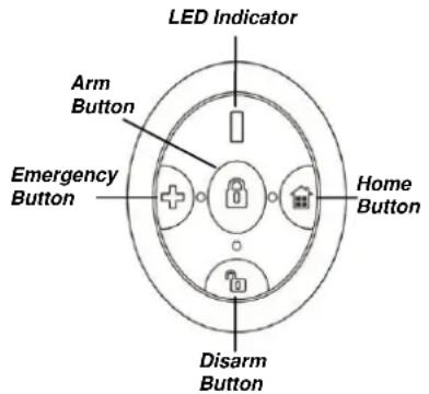
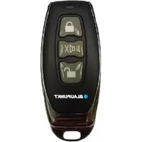
Remote Controller
The Remote Controller can be carried with the user to control the alarm system mode. You can also use the Panic button on the Remote Controller to activate a Panic alarm at any time regardless of system mode.
Parts Identification:
- LED Indicator:
The LED Indicator will light up when the Remote Controller is transmitting signal.
- Away Arm Button:
Press the button to Away Arm the alarm system.
- Home Arm Button:
Press the button to Home Arm the alarm system.
- Disarm Button:
Press the button to Disarm the alarm system.
- Panic Button:
Press and hold the button for 3 seconds to activate a Panic alarm.
- Battery Cover:
Insert a coin into the slot and turn counter-clockwise to open the cover and insert battery, then turn clockwise to tighten.

System Extension
Aside from the devices included in the package, you can further improve the capability of your alarm system by purchasing extra accessories. Such as extra PIR Sensor or Door Contact to extend your protection area; Remote Keypad for a secondary system operation platform; Smoke Detector for fire protection; Temperature Sensor for temperature update; and more Power Switch for energy management and Home Automation. For information about more accessory devices, please visit www.blaupunkt.com
Before proceeding to install your accessory devices, you should first complete system registration on the Blaupunkt Home Connect server. Please refer to the Quick Start Guide or the server user manual to complete the registration process and log into your user account.
Signal Range and Walk Test
All accessory devices in the Q3200 alarm kit use wireless radio protocol to communicate with the Control Panel, saving you from the extra labor of wiring the device to the panel. All devices in the alarm system have an approximate range of 30 meters in a typical domestic environment. The range may vary depending on different home conditions. Before installing an accessory device, you should test its signal range at the selected mounting location first. To test signal range, use the Walk Test function from the Blaupunkt Home Connection server, then press the device's test button to transmit a test signal. Refer to the server user manual for more info.
Home Arm Mode Planning
The alarm system functions according to its current "Mode," which determines the system behavior when a sensor is activated. There are 3 modes:
Disarm Mode: The system will not activate an alarm when a Burglar protection sensor, such as a Door/Window Contact or PIR sensor, is triggered. It will only activate an alarm if the user does so manually, or a Fire/Water sensor is triggered.
Away Arm Mode: The system will activate an alarm when any sensor is triggered.
Home Arm Mode: The system will only activate a Burglar alarm from specific sensors. Sensors set to be ignored under Home Arm mode will not activate an alarm when triggered. With Home Arm mode, you can keep your home perimeter under alert and still be able to move freely within the house.
Home Arm mode allows the system to be partially armed by deactivating some sensors under Home Arm mode. Before installation, you should plan ahead and determine which sensors should be deactivated for Home Arm mode. Usually, sensors deployed at the home perimeter and entry points, such as a Door Contact on the front gate, should be activated all the time. While sensors located in internal spaces, such as the 2nd floor, can be deactivated for Home Arm mode. For more info about Home Arm mode settings, please refer to the server user manual.
Tamper Protection
Your intrusion protection sensors (PIR Camera and Door Contact) are protected from sabotage attempts by a "tamper switch," which is triggered when the device cover is opened or removed from the mounted surface. When the tamper switch is triggered, the sensor will transmit a signal to the Control Panel to alert the user that the sensor may be either installed improperly or has been sabotaged. To make sure the tamper switch functions properly, please make sure the switch is fully depressed against the mounting surface when installing your accessory devices.
General Device Location Guideline
- Avoid mounting the Control Panel and devices close to large metal objects or electrical interference sources, such as refrigerators and microwave ovens, as they could affect signal strength. Wall material also plays a great role in signal penetration efficiency; for example, a brick wall will reduce signal strength a lot more than a wooden wall.
- For devices that have tamper protection function, mount on an even surface to ensure the tamper is fully closed when mounted. For uneven surfaces, use extra packing material on the back.
Device Location Planning:

Mounting
Door Contact
- Pull out the plastic battery insulator on the back to activate the battery and power on the Door Contact.
- The Door Contact should be mounted on the door/window frame, while the magnet should be mounted on the door/window aligned with the Rib Mark on the Door Contact. The gap between the Door Contact and the magnet should be no more than 15 mm.
- Choose to install the Door Contact with either screws or adhesive tape. Screw Mounting
The Door Contact has two knockouts on the inside of the back cover where the plastic is thinner for wall mounting.
- Open the Door Contact back cover to reveal the knockouts, break through the knockouts, and use the knockouts to mark the position on the door or window frame.
- Drill holes into the door or window frame at the marked location, and insert plugs if needed.
- Screw the back cover into the marked location and replace the front cover.
- Screw the magnet onto the door; the position of the magnet should be aligned with the rib mark on the Door Contact at the same height. If the magnet cannot be placed at the same height as the Door Contact, a spacer is provided in the package to increase the magnet height.
Adhesive Mounting


Before mounting with double-sided adhesive tape, you should clean the mounting location with a degreaser and make sure there is no cracked paint or uneven surface.
- Peel the cover off the double-sided adhesive tape, apply the tape to the back of the Door Contact, then attach the Door Contact to the door or window frame.
- Use another piece of double-sided adhesive tape to install the magnet on the door or window.
PIR Camera
The PIR Camera has knockouts on the back where the plastic is thinner. The 2 center knockouts are for flat wall mounting, and the 4 side knockouts are for corner mounting.
- Pull out the plastic battery insulator on the back to activate the batteries and power on the PIR Camera.
- Open the PIR Camera back cover, break through the knockouts, and use the knockouts to mark the position on the wall or corner.
- Drill holes into the wall or corner at the marked location, and insert wall plugs if needed.
- Screw the back cover into the marked location and replace the front cover.

This chapter covers the potential issues you may encounter during system operation, and the factory reset function.
Control Panel
Control Panel Fault: An orange LED indicates a fault in the system. When the LED lights up, please log in to your Blaupunkt Home Connection Server account to check fault events. The possible fault events include:
● Control Panel / Devices low battery:
-- Change device batteries or charge the Control Panel battery accordingly.
- AC power fail:
-- Check the AC power connection.
● Sensor out of order:
-- Check device battery status and conduct a Walk Test to confirm if the Control Panel can receive the device signal.
● Device tamper:
-- Close the accessory device tamper switch by checking the mounted location and cover screw.
- Interference:
-- Perform a Walk Test on all your devices to check if the Control Panel can still receive their signals.
PIR Camera
- PIR Camera LED flashes when activated:
-- PIR is on low battery or the tamper switch is triggered.
● PIR does not respond to movement:
-- PIR has a built-in 1-minute sleep timer after detecting movement. PIR will not re-detect movement within 1 minute after it is triggered. Please wait at least 1 minute before testing PIR again.
-- Battery exhausted, please change the battery.
● PIR is slow to respond:
-- This is normal. PIR has a sophisticated false alarm filter setting to prevent accidental triggers. It is also less sensitive when walking directly toward it.
- PIR gives false alarm:
-- Make sure pets have no access to protected area.
-- Make sure the PIR is not pointed at source of heat or moving objects.
Door Contact
● Door Contact LED flashes when activated:
-- Door Contact is on low battery or tamper switch triggered.
● Door Contact does not respond to door/window opening
-- Batteries exhausted, please change battery.
-- The magnet is too far away from the Door Contact, please check the gap between the magnet and the Door Contact. Reduce the gap and test the Door Contact again.
Remote Controller
- Remote Controller LED glows dimly when any key is pressed -- Remote Controller on low battery.
Factory Reset
The Factory Reset function will clear all device info and returns all system parameter to default value. After resetting you will need to setup the system by following the instruction in server user manual.
- Power down Control Panel by disconnecting AC Power and switching off battery switch.
- Apply AC Power while holding down the button on the back.
- Keep holding the button for about 5 seconds until the panel emits a long beep and turn on all 3 LEDs.
- Release button, factory reset is complete.
All Devices
Environmental Condition
-10°C to 40°C, relative humidity 85% non-condensing for Control Panel and all devices.
Radio Operation Range
About 30m in typical domestic installation, range varies depending on building construction, device location, and environment.
Control Panel
Siren Output
96 dBA sound pressure @ 1m minimum
Zones
40 radio devices.
Radio Frequency
868MHZ & 2.4 GHz
Power Supply
DC9V 1A Power Adaptor
Battery
4.8V 1100mAh Ni-MH Rechargeable Battery, charge time 72 hours.
Battery Backup Time
15 hours
PIR Sensor
Radio Frequency
2.4 GHz
Battery
2 x 1.5V AA alkaline batteries
Door Contact
Radio Frequency
868MHz
Battery
1 x CR2 3V lithium battery
Remote Controller
Radio Frequency
868MHz
Battery
1 x CR2032 3V lithium coin cell
Compliance Statement
Declaration of Conformity
This device complies with the requirements of the R&TTE Directive 1999/5/EC and the following harmonized standards have been applied:
This device complies with Part 15 of the FCC Rules. Operation is subject to the following two conditions:
(1) This device may not cause harmful interference, and (2) This device must accept any interference received, including interference that may cause undesired operation.
FCC Caution:
To assure continued compliance, any changes or modifications not expressly approved by the party responsible for compliance may void the user's authority to operate this equipment. (Example - use only shielded interface cables when connecting to computer or peripheral devices).
Blaupunkt Competence Center Security & Care
Azure Security & Care Corporation
www.blaupunkt.com
6F., No.1, Lane 250, Sinhu 2nd Rd.,
Neihu, Taipei 114, Taiwan



- Q3200 SMART HOME ALARM
- KIT CONTENT AND INSTALLATION GUIDE
- TABLE OF CONTENTS
- INTRODUCTION
- KIT CONTENTS
- CONTROL PANEL
- IMPORTANT NOTE
- ACCESSORIES
- DOOR CONTACT
- PIR CAMERA
- REMOTE CONTROLLER
- PARTS IDENTIFICATION
- SYSTEM EXTENSION
- SIGNAL RANGE AND WALK TEST
- HOME ARM MODE PLANNING
- TAMPER PROTECTION
- GENERAL DEVICE LOCATION GUIDELINE
- DEVICE LOCATION PLANNING
- MOUNTING
- ADHESIVE MOUNTING
- FACTORY RESET
- ALL DEVICES
- ENVIRONMENTAL CONDITION
- RADIO OPERATION RANGE
- SIREN OUTPUT
- ZONES
- RADIO FREQUENCY
- POWER SUPPLY
- BATTERY
- BATTERY BACKUP TIME
- PIR SENSOR
- COMPLIANCE STATEMENT
- DECLARATION OF CONFORMITY
- FCC CAUTION
Brand : BLAUPUNKT
Model : Q3200
Category : Alarm system