
CIR-S1 - Alarm system BLAUPUNKT - Free user manual and instructions
Find the device manual for free CIR-S1 BLAUPUNKT in PDF.


| Product Type | Curtain PIR Motion Sensor (Alarm System Component) |
| Power Supply | 1 x CR123A 3V Lithium Battery (pre-installed) |
| Battery Life | Up to 2 years (typical) |
| Detection Coverage | 10° horizontal, 110° vertical; up to 10 m range (vertical mount at 1.4-1.7 m height) |
| Mounting Options | Vertical wall, horizontal wall, ceiling mount |
| Sensitivity Adjustment | High/Low via jumper JP3 (default Low) |
| Supervision Function | Enable/Disable via jumper JP2 (default Enabled, jumper Off) |
| Sleep Timer | Approximately 1 minute after detection |
| Test Mode | 3 minutes via Learn/Test button (LED indicates movement) |
| LED Indicator | Off (normal operation); On for 2 seconds (tamper, low battery, or movement in test mode) |
| Tamper Switch | Protects against unauthorized cover opening or removal from mounting surface |
| Radio Frequency | 868 MHz |
| Operating Temperature | -10°C to 40°C (85% RH non-condensing) |
| Package Contents | 1 x PIR Sensor, 2 wall plugs and screws, 1 CR123A battery (pre-installed) |
| Low Battery Detection | Notifies control panel when battery voltage is low |
| Learn / Test Button | Transmits learn code to control panel and activates test mode |
Frequently Asked Questions - CIR-S1 BLAUPUNKT
User questions about CIR-S1 BLAUPUNKT
0 question about this device. Answer the ones you know or ask your own.
Ask a new question about this device
Download the instructions for your Alarm system in PDF format for free! Find your manual CIR-S1 - BLAUPUNKT and take your electronic device back in hand. On this page are published all the documents necessary for the use of your device. CIR-S1 by BLAUPUNKT.
USER MANUAL CIR-S1 BLAUPUNKT
Curtain PIR Motion Sensor (CIR-S1)


Parts Description
1. LED indicator
The LED indicator is located under the front cover and is only visible when it is turned on.
2. Battery Insulator
3. Tamper Switch
The tamper switch protects the PIR from unauthorized cover opening or removal from the mounted surface.
4. Learn/Test Button
Press the button to transmit a learn/test code and enter Test mode for 3 minutes.
5. Supervision Enable/Disable Jumper Switch (JP2)
6. High/Low Sensitivity Jumper Switch (JP3)
Package Content
1 x PIR Sensor, 2 x wall plugs and screws, 1 x CR123A 3V lithium battery (pre-installed)
Supervision Enable/Disable Jumper Switch (JP2)
Jumper On
The jumper link is inserted connecting the two pins.

Jumper Off
if the jumper link is removed or parked on one pin.
If enabled, the PIR sensor will transmit a supervision signal to the Control Panel periodically for the sensor to monitor PIR sensor condition.
Jumper set to ON = supervision function is Disabled Jumper set to OFF = supervision function is Enabled (Default)
High/Low Sensitivity Jumper Switch (JP3)
Jumper On
The jumper link is inserted connecting the two pins.

Jumper Off
if the jumper link is removed or parked on one pin.
Jumper set to ON = PIR sensitivity is set to High
Jumper set to OFF = PIR sensitivity is set to Low (Default)
Learning
Put the Control Panel into learning mode, then press the learn button to transmit the learn code. Please refer to the Control Panel manual to complete the learning process.
Detection Coverage
When mounted vertically, the PIR has a horizontal detection coverage of 10° and vertical detection coverage of 110° to the front. The PIR will only be activated by movement across the 10° horizontal coverage.
Top View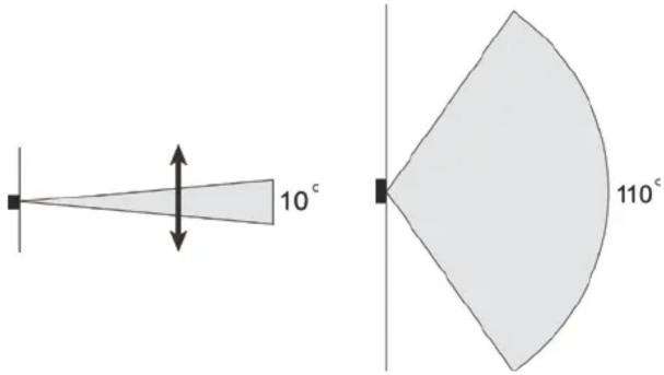
There are 3 ways to mount the PIR for different coverage according to different scenarios.
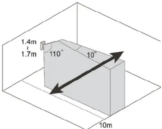
Vertical Wall Mount
Mount the PIR on the wall vertically to protect against anyone attempting to move across the detection area.
When mounted at 1.4~1.7 meter height, the PIR has a detection range of 10 meters against horizontal movement. Avoid mounting outside suggested height or the detection range may be reduced.
Horizontal Wall Mount
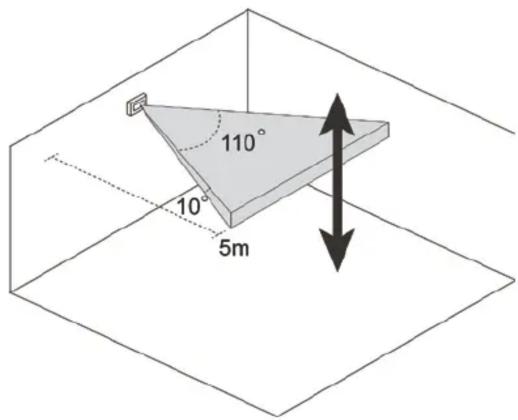
Turn the PIR horizontally and mount on wall to protect against vertical movement across the detection area. This practice is usually used to protect against intruder from sky light and roof hatch.
When mounted horizontally, the PIR has a detection range of 5 meters against vertically movement only. It will NOT be able to detect horizontal movement.
Ceiling Mount
Mount the PIR on ceiling to look downward over a door or window.
When mounted at 2.4~3 meter height and looking down, the PIR has coverage of about 5 meters at ground level.

Installation
The PIR Sensor has knockouts on the back where plastic is thinner for wall or ceiling mounting.
- Break through the knockouts; use the knockouts to mark position on the wall or ceiling.
- Drill holes into the marked location using the knockouts as a template.
- Fix the PIR sensor base onto the wall or ceiling using the screws and plugs provided.
- Replace the PIR sensor cover onto the base.

Operation
Sleep Timer
The PIR features a “sleep time” of approximately 1 minute for power conservation. After transmitting a detected movement, the PIR will not retransmit for 1 minute. Any further movement detected during this sleep period will extend the sleep time by another minute. In this way, continuous movement in front of a PIR will not unduly exhaust the battery.
Test Mode
Press the Test Button to enter Test mode for 3 minutes. Sleep timer will be disabled under Test mode, and the LED indicator will flash every time a movement is detected. Use the Test mode to determine PIR detection coverage and plan the installation location accordingly.
LED Indicator
| Off | Normal Operation |
| On (2 seconds) | - When Tamper Switch is triggered- Movement detection under low battery, tamper triggered, or Test mode. |
Tamper Switch
The tamper switch spring is compressed against the break-away area on the PIR back cover when the cover is closed. When the PIR base is screwed onto the mounting location, a forceful attempt to remove the PIR will cause the break-away area to detach and activate the tamper switch to notify the Control Panel.

Battery
The PIR uses one CR123A 3V lithium battery as its power source. Remove the battery insulator to activate the battery. It also features a low battery detection function to notify the Control Panel when battery voltage is low.
When the PIR is on low battery, follow the procedure below to change the batteries.
- Open the PIR back cover.
- Remove the old battery.
- Press the tamper switch several times to fully discharge.
- Insert the new batteries observing correct polarity. The PIR LED will light up for 30 seconds to indicate it is warming up.
- Replace the PIR back cover.
Specification
Environmental Condition
-10 °C to 40 °C, relative humidity 85% non-condensing.
Radio
868 MHz




- CURTAIN PIR MOTION SENSOR (CIR-S1)
- PARTS DESCRIPTION
- LED INDICATOR
- BATTERY INSULATOR
- TAMPER SWITCH
- LEARN/TEST BUTTON
- SUPERVISION ENABLE/DISABLE JUMPER SWITCH (JP2)
- HIGH/LOW SENSITIVITY JUMPER SWITCH (JP3)
- PACKAGE CONTENT
- JUMPER ON
- JUMPER OFF
- LEARNING
- DETECTION COVERAGE
- VERTICAL WALL MOUNT
- HORIZONTAL WALL MOUNT
- CEILING MOUNT
- INSTALLATION
- OPERATION
- SLEEP TIMER
- TEST MODE
- BATTERY
- SPECIFICATION
- ENVIRONMENTAL CONDITION
- RADIO
Brand : BLAUPUNKT
Model : CIR-S1
Category : Alarm system