
ARMADA 2005 - SUV NISSAN - Free user manual and instructions
Find the device manual for free ARMADA 2005 NISSAN in PDF.
| Product Type | SUV (Sport Utility Vehicle) |
| Brand | Nissan |
| Model | Armada 2005 |
| Dimensions (L x W x H) | 5.28 m x 2.01 m x 1.92 m |
| Wheelbase | 3.13 m |
| Curb Weight | 2,300 kg (approx.) |
| Towing Capacity | Up to 3,855 kg |
| Engine Type | 5.6L V8 gasoline |
| Maximum Power | 305 hp at 4,900 rpm |
| Maximum Torque | 393 Nm at 3,600 rpm |
| Transmission | 5-speed automatic |
| Drive Type | Rear-wheel drive or 4-wheel drive (depending on version) |
| Fuel Tank Capacity | 105 L |
| Seating Capacity | 8 seats |
| Audio System | AM/FM radio, CD player, 6 speakers (standard) |
| Safety Features | Front, side and curtain airbags, ABS, stability control |
| Recommended Tires | 265/70 R18 (front and rear) |
| Engine Oil Type | 5W-30 (API SN grade or higher) |
| Engine Oil Capacity | 6.3 L (with filter) |
| Coolant | Based on ethylene glycol (approx. 14 L) |
| Battery | 12 V, 70 Ah |
| Approximate Range | Approximately 500 km (combined) |
| Recommended Maintenance | Oil change every 10,000 km or 1 year |
| Common Wear Parts | Brake pads, discs, tires, windshield wiper blades |
Frequently Asked Questions - ARMADA 2005 NISSAN
User questions about ARMADA 2005 NISSAN
0 question about this device. Answer the ones you know or ask your own.
Ask a new question about this device
Download the instructions for your SUV in PDF format for free! Find your manual ARMADA 2005 - NISSAN and take your electronic device back in hand. On this page are published all the documents necessary for the use of your device. ARMADA 2005 by NISSAN.
USER MANUAL ARMADA 2005 NISSAN
READ FIRST—THEN DRIVE SAFELY
Welcome to the growing family of new NISSAN owners. This vehicle is delivered to you with confidence. It was produced using the latest techniques and strict quality control.
This manual was prepared to help you understand the operation and maintenance of your vehicle so that you may enjoy many miles (kilometers) of driving pleasure. Please read through this manual before operating your vehicle.
A separate Warranty Information Booklet explains details about the warranties covering your vehicle. The “NISSAN Service and Maintenance Guide” explains details about maintaining and servicing your vehicle. Additionally, a separate Customer Care/Lemon Law Booklet (U.S. only) will explain how to resolve any concerns you may have with your vehicle, as well as clarify your rights under your state’s lemon law.
Your NISSAN dealership knows your vehicle best. When you require any service or have any questions, they will be glad to assist you with the extensive resources available to them.
Before driving your vehicle please read this Owner's Manual carefully. This will ensure familiarity with controls and maintenance requirements, assisting you in the safe operation of your vehicle.
WARNING
IMPORTANT SAFETY INFORMATION REMINDERS FOR SAFETY!
Follow these important driving rules to help ensure a safe and comfortable trip for you and your passengers!
- NEVER drive under the influence of alcohol or drugs.
- ALWAYS observe posted speed limits and never drive too fast for conditions.
- ALWAYS use your seat belts and appropriate child restraint systems. Pre-teen children should be seated in the rear seat.
- ALWAYS provide information about the proper use of vehicle safety features to all occupants of the vehicle.
- ALWAYS review this owner's manual for important safety information.
For descriptions specified for four-wheel drive models, a 4×4 mark is placed at the beginning of the applicable sections/items.
As with other vehicles with features for off-road use, failure to operate four-wheel drive models correctly may result in loss of control or an accident. Be sure to read "Driving safety precautions" in the "Starting and driving" section of this manual.
ON-PAVEMENT AND OFF-ROAD DRIVING
This vehicle will handle and maneuver differently from an ordinary passenger car because it has a higher center of gravity for off-road use. As with other vehicles with features of this type, failure to operate this vehicle correctly may result in loss of control or an accident. Be sure to read “On-pavement and off-road driving precautions”, and “Avoiding collision and rollover”, and “Driving safety precautions”, in the “Starting and driving” section of this manual.
MODIFICATION OF YOUR VEHICLE
This vehicle should not be modified. Modification could affect its performance, safety or durability, and may even violate governmental regulations. In addition, damage or performance problems resulting from modifications may not be covered under NISSAN warranties.
WHEN READING THE MANUAL
This manual includes information for all options available on this model. Therefore, you may find some information that does not apply to your vehicle.
All information, specifications and illustrations in this manual are those in effect at the time of printing. NISSAN reserves the right to change specifications or design without notice and without obligation.
IMPORTANT INFORMATION ABOUT THIS MANUAL
You will see various symbols in this manual. They are used in the following ways:

WARNING
This is used to indicate the presence of a hazard that could cause death or serious personal injury. To avoid or reduce the risk, the procedures must be followed precisely.

CAUTION
This is used to indicate the presence of a hazard that could cause minor or moderate personal injury or damage to your vehicle. To avoid or reduce the risk, the procedures must be followed carefully.
natural_image
Abstract geometric pattern with two intersecting diagonal lines forming an X shape (no text or symbols)APD1005
If you see this symbol, it means “Do not do this” or “Do not let this happen.”


If you see a symbol similar to these in an illustration, it means the arrow points to the front of the vehicle.


Arrows in an illustration that are similar to these indicate movement or action.


Arrows in an illustration that are similar to these call attention to an item in the illustration.
CALIFORNIA PROPOSITION 65 WARNING

WARNING
Engine exhaust, some of its constituents, and certain vehicle components contain or emit chemicals known to the State of California to cause cancer and birth defects or other reproductive harm. In addition, certain fluids contained in vehicles and certain products of component wear contain or emit chemicals known to the State of California to cause cancer and birth defects or other reproductive harm.
© 2004 NISSAN NORTH AMERICA, INC. GARDENA, CALIFORNIA
All rights reserved. No part of this Owner's Manual may be reproduced or stored in a retrieval system, or transmitted in any form, or by any means, electronic, mechanical, photocopying, recording or otherwise, without the prior written permission of Nissan North America, Inc., Gardena, California.
WELCOME TO THE WORLD OF NISSAN
natural_image
Black-and-white line drawing of a modern architectural building with geometric facade and triangular roof, surrounded by trees and water (no text or symbols)NISSAN TECHNICAL CENTER NORTH AMERICA, INC.
in Farmington Hills, Michigan
natural_image
Aerial black-and-white illustration of a large industrial or warehouse complex with multiple rectangular buildings and surrounding landscape (no visible text or symbols)NISSAN MANUFACTURING FACILITY in Smyrna, Tennessee
WFW0002
Your new NISSAN is the result of our dedication to produce the finest in safe, reliable and economical transportation. Your vehicle is the product of a successful worldwide company that manufactures cars and trucks in over 17 countries and distributes them in 170 nations.
NISSAN vehicles are designed and manufactured by NISSAN Motor Co., Ltd. which was founded in Tokyo, Japan in 1933, and NISSAN affiliates worldwide, collectively growing to become the fifth largest automaker in the world. In addition to cars and trucks, NISSAN also makes forklift trucks, marine engines, boats and other diversified products.
NISSAN has made a substantial and growing investment in North America. NISSAN's commitment is over \$6 billion dollars in capital investments in facilities across the continent. Some of the facilities include the NISSAN Manufacturing facilities in Canton, Mississippi and in Smyrna, Tennessee, vehicle styling design at NISSAN Design America, Inc. in San Diego, California, and engineering at NISSAN Technical Center North America in Farmington Hills, Michigan. Additionally, NISSAN employs more than 21,000 people throughout the United States, Canada, and Mexico. An additional 60,000 people work for the 1,250 NISSAN and INFINITI dealers across North America.
NISSAN is also a substantial contributor to the Canadian economy. NISSAN Canada Inc., its suppliers and over 150 dealers employ approximately 4,500 people. These include company employees and the staffs of NISSAN dealers all across Canada. In addition, many Canadians work for companies that supply NISSAN and NISSAN dealers with materials and services ranging from the operation of port facilities and transportation services, to the supply of lubricants, parts and accessories.
NISSAN pioneered the use of electronics and computers in automobiles, and has led the industry in improving both performance and fuel efficiency through new engine designs and the use of synthetic materials to reduce vehicle weight. The company has also developed ways to build quality into its vehicles at each stage of the production process, both through extensive use of automation and — most importantly — through an awareness that people are the central element in quality control.
From the time the parts arrived from our suppliers until you took delivery of your new NISSAN, dozens of checks were made to ensure that only the best job was being done in producing and delivering your vehicle. NISSAN also takes great care to ensure that when you take your NISSAN to your dealer for maintenance, the service technician will perform his work according to the quality standards that have been established by NISSAN.
Safety has also been built into your NISSAN. As you know, seat belts are an integral part of the safety systems that will help protect you and your passengers in the event of a sudden stop or an accident. We urge you to use the seat belts every time you drive the vehicle.
The NISSAN story of growth and achievement reflects our major goal: to provide you, our customer, with a vehicle that is built with quality and craftsmanship — a product that we can be proud to build and you can be proud to own.
NISSAN CUSTOMER CARE PROGRAM
NISSAN CARES ...
Both NISSAN and your NISSAN dealer are dedicated to serving all your automotive needs. Your satisfaction with your vehicle and your NISSAN dealer are our primary concerns. Your NISSAN dealer is always available to assist you with all your automobile sales and service needs.
However, if there is something that your NISSAN dealer cannot assist you with or you would like to provide NISSAN directly with comments or questions, please contact the NISSAN Consumer Affairs Department using our toll-free number:
For U.S. customers
1-800-NISSAN-1
(1-800-647-7261)
For Canadian customers
1-800-387-0122
The Consumer Affairs Department will ask for the following information:
- Your name, address, and telephone number
- Vehicle identification number (attached to the top of the instrument panel on the driver's side)
- Date of purchase
- Current odometer reading
- Your NISSAN dealer's name
- Your comments or questions
OR
You can write to NISSAN with the information at:
For U.S. customers
Nissan North America, Inc.
Consumer Affairs Department
P.O. Box 191
Gardena, California 90248-0191
For Canadian customers
Nissan Canada Inc.
5290 Orbitor Drive
Mississauga, Ontario L4W 4Z5
We appreciate your interest in NISSAN and thank you for buying a quality NISSAN vehicle.
Table of Contents
| Illustrated table of contents |
| Safety—Seats, seat belts and supplemental restraint system |
| Instruments and controls |
| Pre-driving checks and adjustments |
| Display screen, heater, air conditioner and audio systems |
| Starting and driving |
| In case of emergency |
| Appearance and care |
| Maintenance and do-it-yourself |
| Technical and consumer information |
| Index |
| 0 |
| 1 |
| 2 |
| 3 |
| 4 |
| 5 |
| 6 |
| 7 |
| 8 |
| 9 |
| 10 |
0 Illustrated table of contents
Airbags, seat belts and child restraints....0-2
Exterior front 0-3
Exterior rear....0-4
Passenger compartment 0-5
Instrument panel....0-6
Engine compartment check locations 0-8
Warning/indicator lights 0-9
AIRBAGS, SEAT BELTS AND CHILD RESTRAINTS
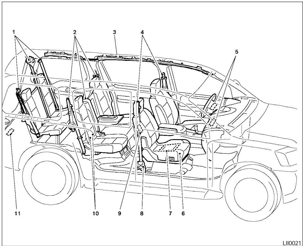
- 3rd row bench seat belts (P. 1-15)
- 2nd row seat belts (P. 1-15)
- Supplemental curtain side-impact and rollover air bags (P. 1-56)
- Front seat belts (P. 1-15)
- Supplemental front impact air bags (P.1-56)
- Seats (P. 1-2)
- Occupant classification sensor (weight sensor) (P.1-63)
- Seat belt pre-tensioners (P. 1-69)
- Supplemental side impact air bag (if so equipped) (P. 1-56)
- LATCH (Lower Anchors and Tethers for CHildren) (P. 1-42)
- Top tether strap anchor (P. 1-44)
See the page number indicated in parentheses for operating details.

- Engine hood (P. 3-9)
- Windshield wiper and washer switch (P. 2-22)
- Windshield (P. 8-17)
- Power windows (P. 2-45)
- Door locks, keyfob, keys (P. 3-3, 3-5, 3-2)
- Mirrors (P. 3-18)
- Tire pressure (P. 9-11)
- Flat tire (P. 6-2)
- Tire chains (P. 8-38)
- Replacing bulbs (P. 8-28)
- Headlight and turn signal switch (P. 2-24)
- Fog light switch (P. 2-28)
- Tow hooks (if so equipped) (P. 6-12)
See the page number indicated in parentheses for operating details.
EXTERIOR REAR
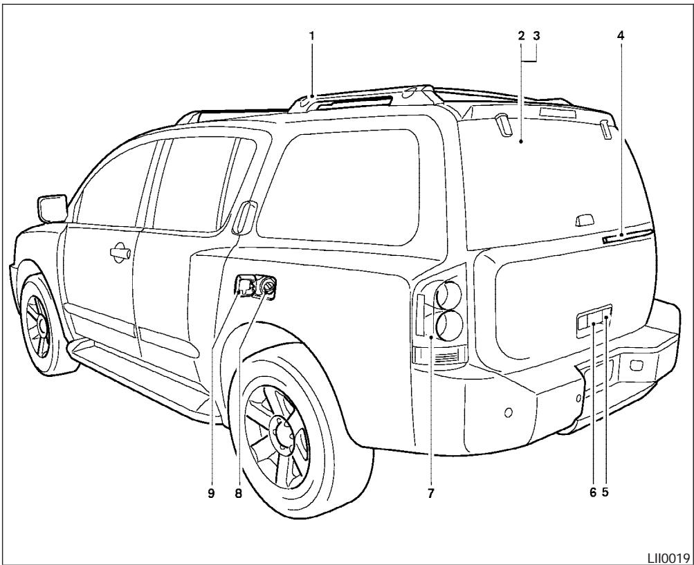
- Roof rack (P. 2-44)
- Vehicle loading (P. 9-12)
- Glass hatch (P. 3-14)
- Rear window washer (P.2-23)
- Glass hatch release (P.3-14)
- Back door release (P. 3-12)
- Replacing bulbs (P. 8-28)
- Fuel filler cap, fuel recommendation (P. 3-14, P. 9-3)
- Fuel filler door (P. 3-14)
See the page number indicated in parentheses for operating details.
PASSENGER COMPARTMENT
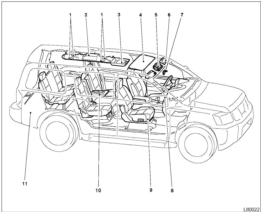
- Rear ventilators (P. 4-14
- Storage (P. 2-33)
- DVD entertainment system (if so equipped) (P. 4-40)
- Sunroof (if so equipped) (P. 2-48)
- Map lights (P. 2-51)
- Sun visors (P. 3-17)
- HomeLink ® (P. 2-52)
- Glove box (P. 2-34)
- Seats (P. 1-2)
- Cup holders (P. 2-38)
- Luggage storage (P. 2-41)
See the page number indicated in parentheses for operating details.
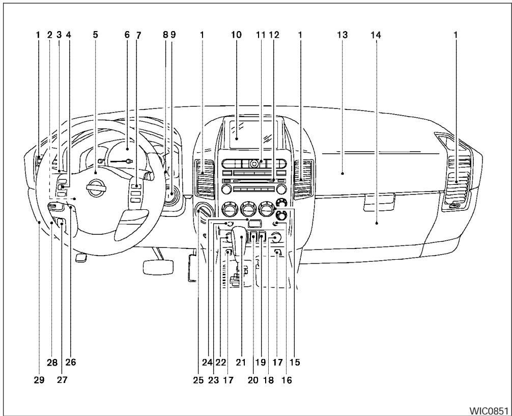
- Ventilators (P. 4-14)
- Instrument brightness control (P. 2-27)
- Headlight/fog light (if so equipped)/turn signal switch (P. 2-24)
- Steering wheel switch for audio control (P. 4-37)
- Driver supplemental air bag/horn (P. 1-56, P. 2-29)
- Meters, gauges and warning/indicator lights (P. 2-3, 2-12)
- Cruise control main/set switches (P. 5-14)
- Windshield wiper/washer switch and rear window wiper/washer switch (P. 2-22, P. 2-23)
- Ignition switch (P. 5-7)
- Navigation system* (if so equipped) (P. 4-2)
- Navigation system* controls (if so equipped) (P. 4-2)
- Audio system controls (P. 4-28, 4-31)
- Front passenger supplemental air bag (P. 1-56)
- Glove box (P. 2-35)
- Climate controls (P. 4-15, 4-24)
-
Aux jack (if so equipped) (P. 4-36)
-
Heated seat switch (if so equipped) (P. 2-29)
- Power outlet/cigarette lighter (accessory) (P. 2-31/P. 2-32)
- Vehicle dynamic control (VDC) off switch (P. 2-30)
- Tow mode switch (P. 2-31)
- Shift selector lever (P. 5-9)
- Power outlet (P. 2-31)
- Front passenger air bag status light (P. 1-65)
- Hazard lights (P. 2-28)
- 4WD shift switch (if so equipped) (P. 5-17)
- Tilt steering wheel control (P. 3-16)
- Rear sonar system off switch (if so equipped) (P. 2-30)
- Pedal position adjustment switch (P. 3-16)
- Back door open/close switch (if so equipped) (P. 3-9)
*: Refer to the separate Navigation System Owner's Manual (if so equipped).
See the page number indicated in parentheses for operating details.
ENGINE COMPARTMENT CHECK LOCATIONS

- Battery (P. 8-13)
- Fuse/fusible link box (P. 8-21)
- Transmission dipstick (P. 8-11)
- Engine oil filler cap (P. 8-8)
- Brake fluid reservoir (P. 8-12)
- Windshield washer fluid reservoir (P. 8-12)
- Air cleaner (P. 8-16)
- Radiator cap (P. 8-7)
- Power steering fluid reservoir (P. 8-11)
- Engine oil dipstick (P. 8-8)
- Engine coolant reservoir (P. 8-7)
See the page number indicated in parentheses for operating details.
WARNING/INDICATOR LIGHTS
| Warning light | Name | Page |
| Anti-lock brake warning light | 2-13 | |
| Automatic transmission check warning light | 2-13 | |
| Automatic transmission park warning light (4x4 model) | 2-13 | |
| Brake warning light | 2-13 |
| Warning light | Name | Page |
 | Charge warning light | 2-14 |
 | Check suspension warning light (if so equipped) | 2-14 |
 | Door open warning light | 2-14 |
 | Engine oil pressure low/engine coolant temperature high warning light | 2-14 |
 | 4WD warning light ( 4x4 model) | 2-15 |
| Warning light | Name | Page |
 | Low fuel warning light | 2-15 |
 | Low tire pressure warning light | 2-15 |
 | Low windshield washer fluid warning light | 2-16 |
 | Seat belt warning light and chime | 2-16 |
 | Supplemental air bag warning light | 2-16 |
| Indicator light | Name | Page |
| Automatic transmission position indicator light | 2-17 | |
| Cruise main switch indicator light | 2-17 | |
| Cruise set switch indicator light | 2-17 | |
| 4WD shift indicator light(4x4 model) | 2-17 | |
| Front passenger air bag status light | 2-17 |
| Indicator light | Name | Page |
| Automatic transmission position indicator light | 2-17 | |
| Cruise main switch indicator light | 2-17 | |
| Cruise set switch indicator light | 2-17 | |
| 4WD shift indicator light(4x4 model) | 2-17 | |
| Front passenger air bag status light | 2-17 |
| Indicator light | Name | Page |
| High beam indicator light (Blue) | 2-17 | |
| Malfunction indicator lamp (MIL) | 2-17 | |
| Security indicator light (NVIS) | 2-18 | |
| Slip indicator light | 2-18 | |
| Transfer 4LO position indicator light (model) | 2-18 | |
| Turn signal/hazard indicator lights | 2-19 |
| Indicator light | Name | Page |
| Vehicle dynamic control off indicator light | 2-19 |
1 Safety—Seats, seat belts and supplemental restraint system
Seats 1-2
Front manual seat adjustment — passenger's side 1-2
Front power seat adjustment (for driver's seat and if so equipped for passenger's seat) 1-4
2nd row captain's chair adjustment (if so equipped) 1-5
2nd row bench seat adjustment (if so equipped) 1-7
Head restraint adjustment 1-8
Active head restraint (front seats)....1-9
Armrests 1-10
Flexible seating....1-10
Seat belts 1-15
Precautions on seat belt usage....1-15
Child safety....1-17
Pregnant women 1-19
Injured persons....1-19
Three-point type seat belt with retractor....1-19
Seat belt extenders....1-24
Seat belt maintenance 1-25
Child restraints....1-25
Precautions on child restraints ....1-25
Child restraint installation on 2nd row captain's chairs ....1-27
Child restraint installation on 2nd row bench seats (if so equipped)....1-31
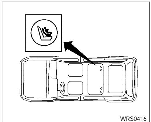
Child restraint installation on 3rd row bench seat....1-36
LATCH (Lower Anchors and Tethers for CHildren) system....1-42
Top tether strap child restraint 1-44
Child restraint installation on front passenger seat....1-47
Booster seats....1-50
Precautions on booster seats 1-50
Supplemental restraint system 1-56
Precautions on supplemental restraint system 1-56
Supplemental air bag warning labels....1-70
Supplemental air bag warning light 1-71
natural_image
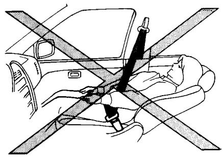
Diagram showing car seatbelt and seatbelt crossed in a car (no text or symbols)ARS1152
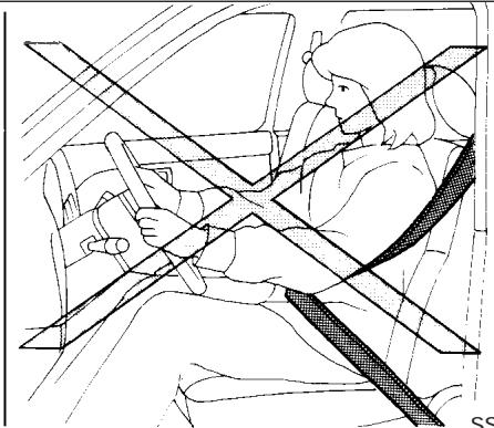
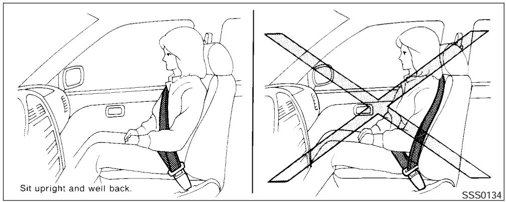
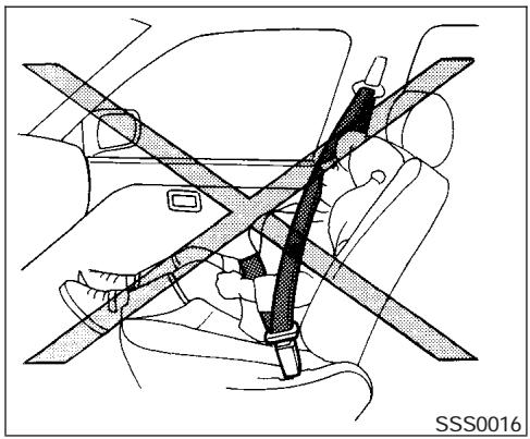
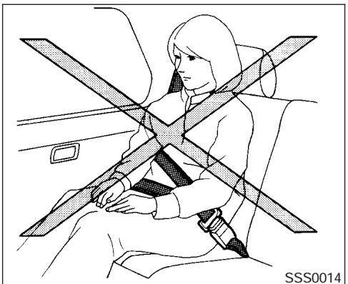
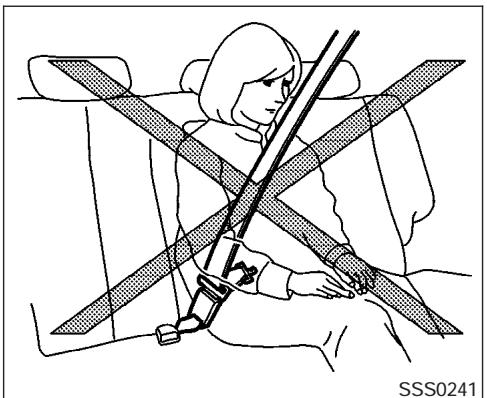
WARNING
- Do not ride in a moving vehicle when the seatback is reclined. This can be dangerous. The shoulder belt will not be against your body. In an accident, you could be thrown into it and receive neck or other serious injuries. You could also slide under the lap belt and receive serious internal injuries.
- For the most effective protection when the vehicle is in motion, the seat should be upright. Always sit well back in the seat and adjust the seat properly. See "Precautions on Seat Belt Usage" later in this section.
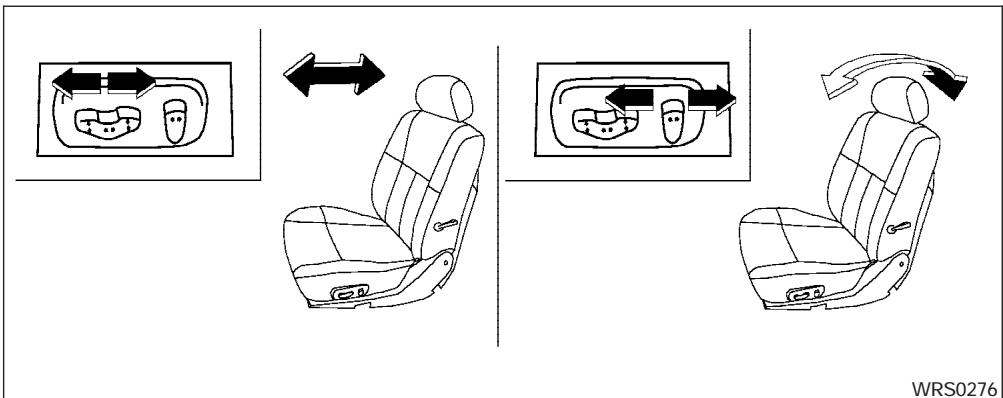
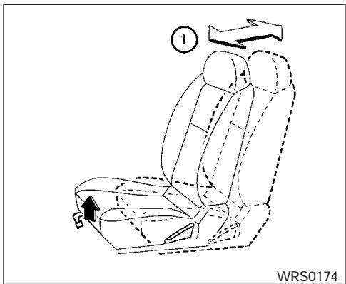
FRONT MANUAL SEAT ADJUSTMENT — PASSENGER'S SIDE
WARNING
- Do not adjust the driver's seat while driving so full attention may be given to vehicle operation. The seat may move suddenly and could cause loss of control of the vehicle.
- After adjustment, gently rock in the seat to make sure it is securely locked.
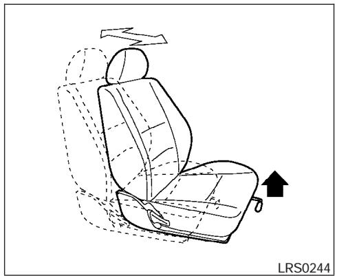
natural_image
Line drawing of a car seat assembly with dashed outlines and an arrow indicating direction (no text or symbols)Forward and backward
Pull the lever up and hold it while you slide the seat forward or backward to the desired position. Release the lever to lock the seat in position.
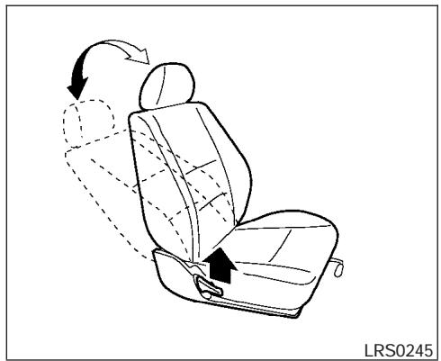
natural_image
Line drawing of a car seat assembly with arrows indicating rotation and movement (no text or symbols)Reclining
To recline the seatback, pull the lever up and lean back. To bring the seatback forward, pull the lever up and lean your body forward. Release the lever to lock the seatback in position.
The reclining feature allows adjustment of the seatback for occupants of different sizes for added comfort and to help obtain proper seat belt fit. See “Precautions on seat belt usage” later in this section. Also, the seatback can be reclined to allow occupants to rest when the vehicle is stopped.

WARNING
After adjustment, gently rock in the seat to make sure it is securely locked.
FRONT POWER SEAT
ADJUSTMENT (for driver's seat and if so equipped for passenger's seat)
WARNING
- Do not adjust the driver's seat while driving so full attention may be given to vehicle operation. The seat may move suddenly and could cause loss of control of the vehicle.
- Do not leave children unattended inside the vehicle. They could unknowingly activate switches or controls. Unattended children could become involved in serious accidents.
Operating tips
- The power seat motor has an auto-reset overload protection circuit. If the motor stops during operation, wait 30 seconds, then reactivate the switch.
- Do not operate the power seat switch for a long period of time when the engine is off. This will discharge the battery.
See “Automatic drive positioner (if so equipped)” in “Pre-driving checks and adjustments” for automatic drive positioner operation.
Forward and backward
Moving the switch forward or backward will slide the seat forward or backward to the desired position.
Reclining
Move the recline switch backward until the desired angle is obtained. To bring the seatback forward again, move the switch forward and move your body forward. The seatback will move forward.
The reclining feature allows adjustment of the seatback for occupants of different sizes for added comfort and to help obtain proper seat belt fit (see "Precautions on seat belt usage" later in this section). Also, the seatback can be reclined to allow occupants to rest when the vehicle is stopped.
1-4 Safety—Seats, seat belts and supplemental restraint system
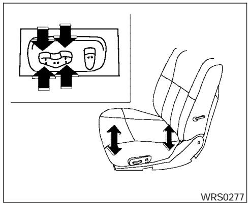
Seat lifter (driver's seat)
Push the front or rear end of the switch up or down to adjust the angle and height of the seat cushion.

natural_image
Line drawing of a car seat with directional arrows indicating rotation (no text or symbols)Lumbar support (driver's seat)
The lumbar support feature provides lower back support to the driver. Move the lever up or down to adjust the seat lumbar area.
natural_image
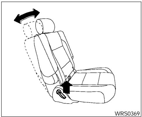
Line drawing of a car seatbelt with directional arrows indicating movement (no text or symbols)2ND ROW CAPTAIN'S CHAIR ADJUSTMENT (if so equipped)
Reclining
To recline the seatback, pull up on the lever and lean back.
The recline feature allows adjustment of the seat back for occupants of different sizes for added comfort and to help obtain proper seat belt fit (see “Precautions on seat belt usage” later in this section). Also, the seatback can be reclined to allow occupants to rest when the vehicle is stopped.

WARNING
- After adjustment, gently rock in the seat to make sure it is securely locked.
- Do not ride in a moving vehicle when the seatback is reclined. This can be dangerous. The shoulder belt will not be against your body. In an accident, you could be thrown into it and receive neck or other serious injuries. You could also slide under the lap belt and receive serious internal injuries.
- For the most effective protection when the vehicle is in motion, the seat should be upright. Always sit well back in the seat and adjust the seat belt properly. See “Precautions on seat belt usage” later in this section.
WRS0415
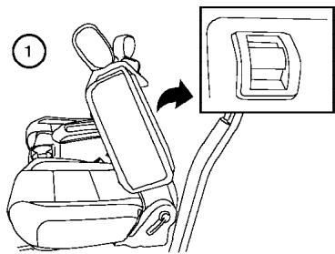
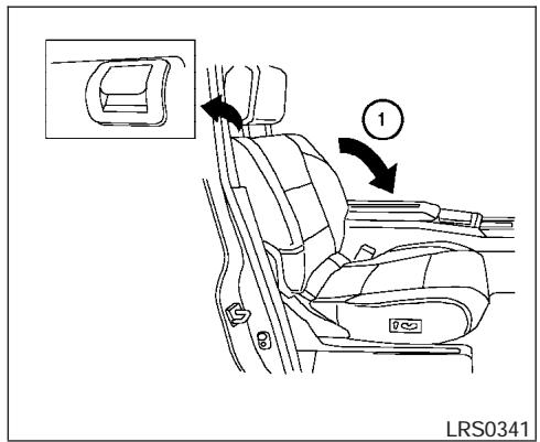
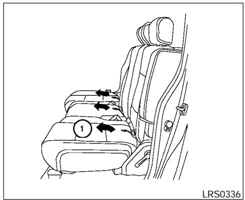
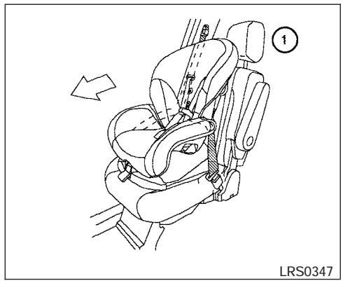
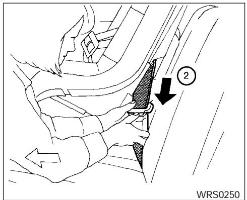
Tip up for easy entry to the 3rd row
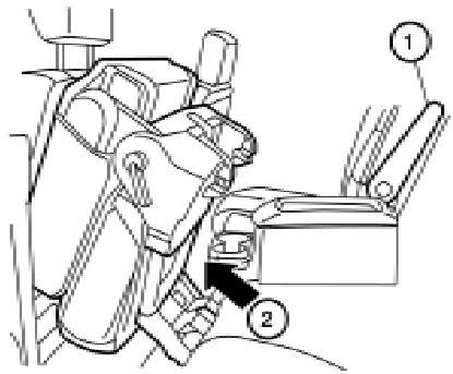
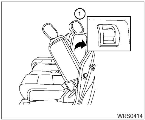
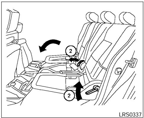
The 2nd row captain's chairs can be tipped forward for easy entry or exit from the 3rd row bench seat. To enter the 3rd row ① raise the armrest so it is parallel to the seatback and in the stowed position, then lift up on the latch located on the upper corner of the seatback on the 2nd row captain's chair and fold the seatback forward at an angle over the seat base. This will release the back of the seat so it may be tipped forward.
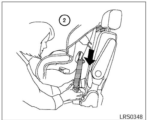
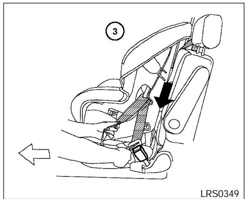
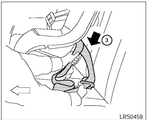
LRS0372
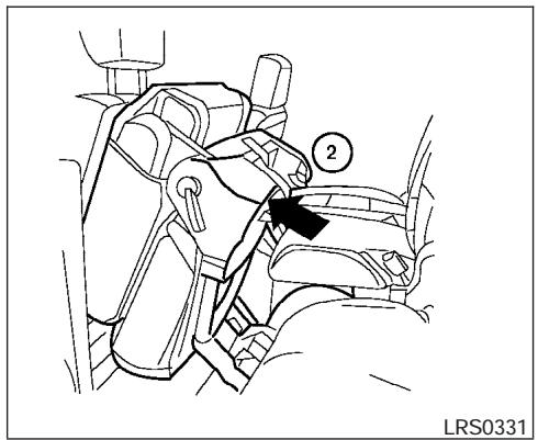
Then ② lift up on the lower corner of the seat base and tip the 2nd row captain's chair forward. To exit the 3rd row bench seat lift up on the same latch and fold the seatback forward onto the seat base. Then lift up on the seat base and tip it forward.

natural_image
Line drawing of a car seat assembly with arrows indicating left and right motion (no text or symbols)Outboard seats
2ND ROW BENCH SEAT ADJUSTMENT (if so equipped)
Reclining
To recline the seatback, pull up on the lever and lean back.
The recline feature allows adjustment of the seat back for occupants of different sizes for added comfort and to help obtain proper seat belt fit (see “Precautions on seat belt usage” later in this section). Also, the seatback can be reclined to allow occupants to rest when the vehicle is stopped.
WARNING
- After adjustment, gently rock in the seat to make sure it is securely locked.
- Do not ride in a moving vehicle when the seatback is reclined. This can be dangerous. The shoulder belt will not be against your body. In an accident, you could be thrown into it and receive neck or other serious injuries. You could also slide under the lap belt and receive serious internal injuries.
- For the most effective protection when the vehicle is in motion, the seat should be upright. Always sit well back in the seat and adjust the seat belt properly. See “Precautions on seat belt usage” later in this section.
Tip up for easy entry to the 3rd row
The outboard seating positions on the 2nd row bench seat can be tipped forward for easy entry or exit from the 3rd row bench seat. To enter the 3rd row ① lift up on the latch located on the upper corner of the seatback on the 2nd row bench seat and fold the seatback forward at an angle over the seat base. This will release the back of the seat so it may be tipped forward.
Then ② lift up on the lower corner of the seat base and tip the outboard seating position of the 2nd row bench seat forward. To exit the 3rd row bench seat lift up on the same latch and fold the seatback forward onto the seat base. Then lift up on the seat base and tip it forward.
natural_image
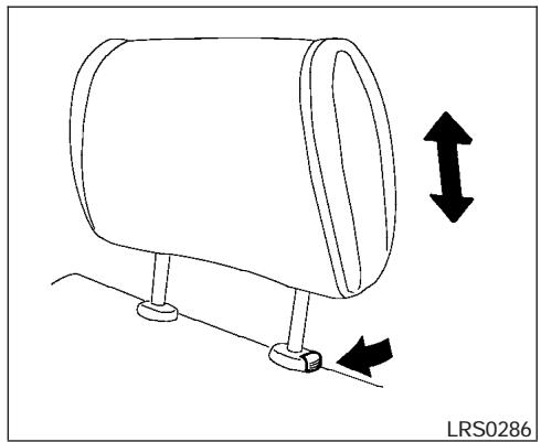
Diagram of a cylindrical device with two vertical arrows indicating upward and downward motion, mounted on a base (no text or symbols)HEAD RESTRAINT ADJUSTMENT
To raise the head restraint, pull it up. To lower, push and hold the lock knob and push the head restraint down.
The head restraints on the 2nd and 3rd row seats are removable. The front seat head restraints are not removable.

WARNING
Head restraints should be adjusted properly as they may provide significant protection against injury in an accident. Do not remove them. Check the adjustment after someone else uses the seat.
natural_image
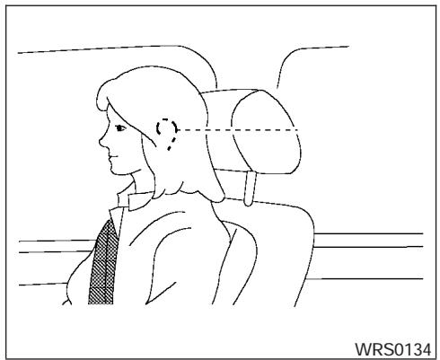
Side profile sketch of a person wearing a seatbelt, viewed from the side (no text or symbols)Adjust the head restraint so the center is level with the center of your ears.
natural_image
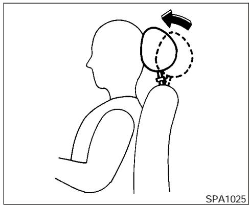
Line drawing of a human head and arm with a balloon and directional arrow, no text or symbols presentACTIVE HEAD RESTRAINT (front seats)
WARNING
- Always adjust the head restraints properly as specified in the previous section. Failure to do so can reduce the effectiveness of the active head restraint.
- Active head restraints are designed to supplement other safety systems. Always wear seat belts. No system can prevent all injuries in any accident.
- Do not attach anything to the head restraint stalks. Doing so could impair active head restraint function.
The head restraint moves forward utilizing the force that the seatback receives from the occupant in a rear-end collision. The movement of the head restraint helps support the occupant's head by reducing its backward movement and helping absorb some of the forces that may lead to whip-lash type injuries.
Active head restraints are effective for collisions at low to medium speeds in which it is said that whiplash injury occurs most.
Active head restraints operate only in certain rear-end collisions. After the collision, the head restraints return to their original positions.
Properly adjust the active head restraints as described earlier in this section.
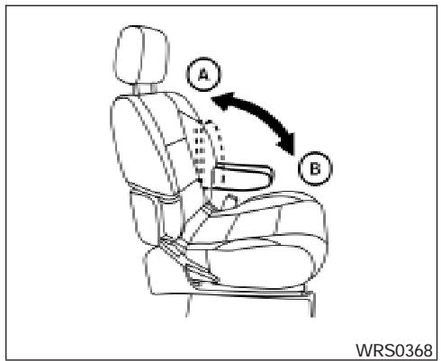
ARMRESTS
To use the armrests, pull them down to the resting position.
Ⓐ Stowed position
B Resting position
FLEXIBLE SEATING
WARNING
- Never allow anyone to ride in the cargo area or on the rear seats when they are in the fold-down position. In a collision, people riding in these areas without proper restraints are more likely to be seriously injured or killed.
-
Do not allow people to ride in any area of your vehicle that is not equipped with seats and seat belts. Be sure everyone in your vehicle is in a seat and using a seat belt properly.
-
Do not fold down the rear seats when occupants are in the rear seat area or any luggage is on the rear seats.
- Head restraints should be adjusted properly as they may provide significant protection against injury in an accident. Always replace and adjust them properly if they have been removed for any reason.
- If the head restraints are removed for any reason, they should be securely stored to prevent them from causing injury to passengers or damage to the vehicle in case of sudden braking or an accident.
- When returning the seatbacks to the upright position, be certain they are completely secured in the latched position. If they are not completely secured, passengers may be injured in an accident or sudden stop.
- Properly secure all cargo to help prevent it from sliding or shifting. Do not place cargo higher than the seatbacks. In a sudden stop or collision, unsecured cargo could cause personal injury.
Folding the front passenger's seatback
To fold the front passenger's seatback flat for extra storage length when transporting long items:
① Slide the seat to the rear-most position. Lift up on the recline lever, located on the outside edge of the seat, and fold the seatback forward as far as it will go. Then lift up on the latch located on the upper corner of the seatback to release the back of the seat.
② Once the seatback is released it will enable you to fold the front passenger seatback flat over the seat cushion.
3. To return the front passenger's seat to a seating position lift up on the seatback and push it up to an upright position. Then pull up on the recline lever and lean the seatback to a proper seating position. Release the lever to lock the seatback in position.
WARNING
- If you fold the front passenger's seat-back flat forward to carry longer objects, be sure this cargo is properly secured and not near an air bag. In a crash, an inflating air bag might force that object toward a person. This could cause severe injury or even death. Secure objects away from the area in which an air bag would inflate. See "Precautions on supplemental restraint system" later in this section.
- Never allow anyone to ride in the cargo area or on the front passenger's seat when it is in the fold-down position. Use of these areas by passengers could result in serious injury in an accident or sudden stop.
Folding the 2nd row captain's chairs (if so equipped)
To fold the 2nd row captain's chairs flat for maximum cargo hauling:
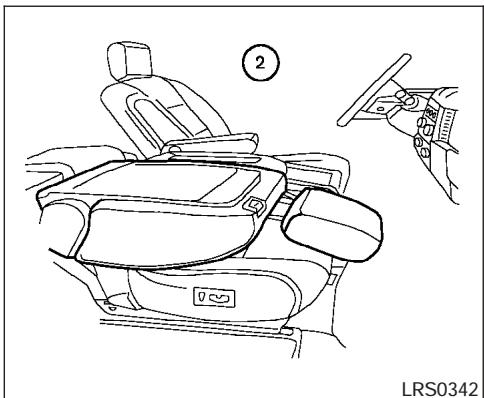
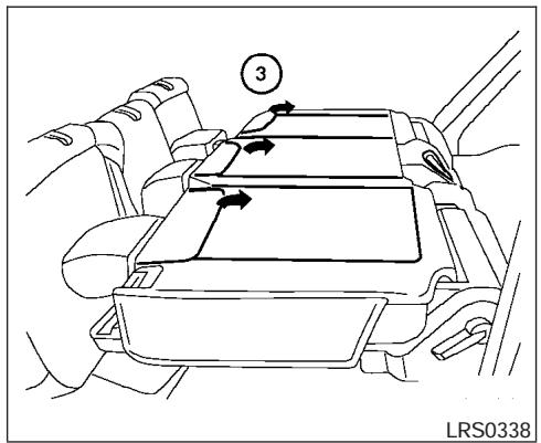
① Raise the armrest to the stowed position. Remove the 2nd row center console, see "Console removal" in the "Instruments and controls" section of this Owner's Manual.
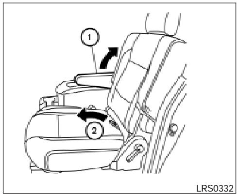
② Pull the strap forward, located in the center of the seat cushion, and fold the seat cushion toward the front of the vehicle.
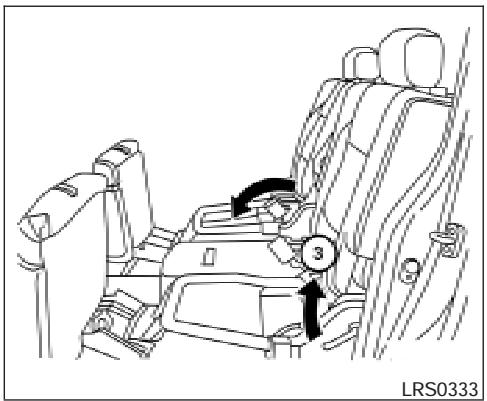
③ Then lift up on the recline lever to fold the seatback flat forward.
natural_image
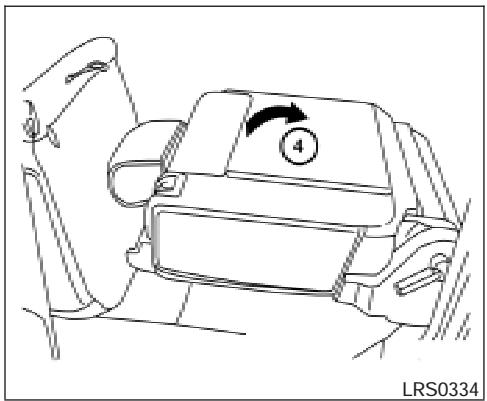
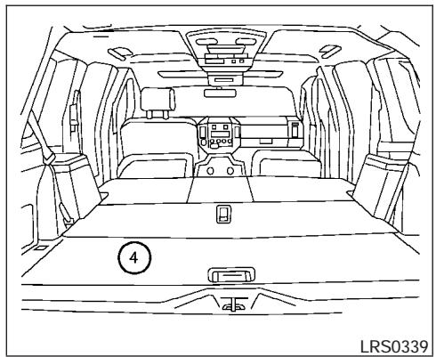
Line drawing of a car interior showing seat, armrest, and dashboard (no text or symbols)④ There is a carpet panel flap that can be folded toward the back of the vehicle.
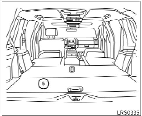
natural_image
Line drawing of a car interior showing dashboard, seats, and seatbelt (no text or symbols)⑤ The carpet panel flaps provide a level cargo floor when the 3rd row seats are also folded flat. Reverse this process to return the 2nd row captain's chairs to a seating position. Make sure to properly raise the seat-back to an upright position and push the seat cushion down into place.
Folding the 2nd row bench seat (if so equipped)
To fold the 2nd row bench seat flat for maximum cargo hauling:
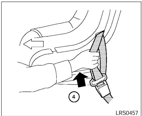
① Pull the strap forward, located in the center of each seat cushion, and fold each seat cushion toward the front of the vehicle.
② Then lift up on the recline lever on the side of the outboard seats to fold the outboard seat-backs flat. To fold the center seatback flat, pull up on the strap on the edge of the center seat cushion and fold the seatback toward the front of the vehicle.
③ There is a carpet panel flap on the back of each seat that can be folded toward the back of the vehicle
natural_image
Line drawing of a car interior showing dashboard, seats, and seatbelt (no text or symbols)④ The carpet panel flap provides a level cargo floor when the 3rd row seats are also folded flat.
- To return the outboard 2nd row bench seats to a seating position reverse the process for the outboard seats.
- To return the center seat to a seating position, lift up on the pull strap on the back of the seat base while lifting on the seatback. Then push the seat cushion back into place. Make sure to hold the seat belts above the seat cushion and properly raise the seatback to an upright position. Then push the seat cushion down into place.
natural_image
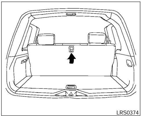
Top-down line drawing of a car backseat with a highlighted seat area and an arrow indicating direction (no text or symbols)Folding the 3rd row bench seat
To fold the 3rd row bench seat flat for maximum cargo capacity:
Disconnect and secure the center seat belt and tongues into the retractor base. See “Stowing the 3rd row center seat belt” later in this section. Then pull up on the latch located in the center of the seatback and fold it forward over the seat base.
To return the 3rd row bench seat to a seating position unfold the seatback and push it back until it latches into position.
SEAT BELTS

WARNING
- When returning the seatbacks, be sure to attach the rear center seat belt connector.
- Do not unfasten the rear center seat belt connector except when folding down the rear seat.
- When attaching the rear center seat belt connector, be certain that the seat-backs are completely secured in the latched position and the rear center seat belt connector is completely secured.
- If the rear center seat belt connector and the seatbacks are not secured in the correct position, serious personal injury may result in an accident or sudden stop.
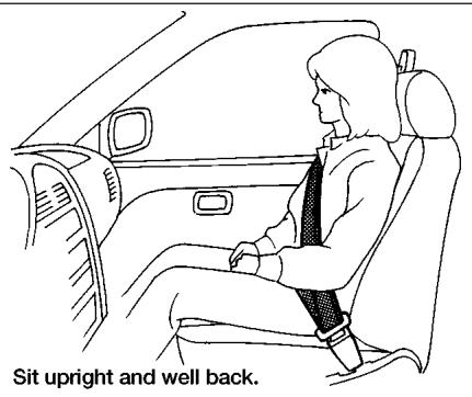
natural_image
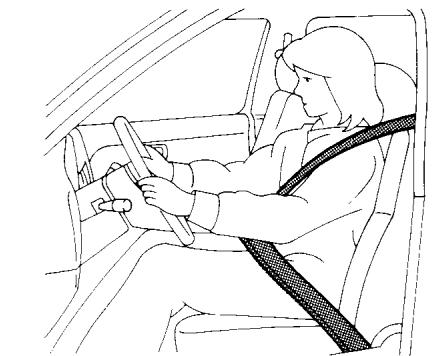
Line drawing of a person wearing a seatbelt inside a car, no text or symbols presentSit upright and well back.
natural_image
Diagram of a person seated in a car with a cross-shaped object on the steering wheel (no text or symbols present)SSS0136
PRECAUTIONS ON SEAT BELT USAGE
If you are wearing your seat belt properly adjusted and you are sitting upright and well back in your seat, your chances of being injured or killed in an accident and/or the severity of injury may be greatly reduced. NISSAN strongly encourages you and all of your passengers to buckle up every time you drive, even if your seating position includes a supplemental air bag.
Most U.S. states and Canadian provinces or territories specify that seat belts be worn at all times when a vehicle is being driven.
natural_image
Diagram of car seatbelt and passenger seatbelt assembly (no text or symbols)WARNING
- Every person who drives or rides in this vehicle should use a seat belt at all times. Children should be properly restrained in the rear seat and, if appropriate, in a child restraint.
WARNING
- The seat belt should be properly adjusted to a snug fit. Failure to do so may reduce the effectiveness of the entire restraint system and increase the chance or severity of injury in an accident. Serious injury or death can occur if the seat belt is not worn properly.
natural_image
Line drawing of a person seated in a car with cross-shaped seatbelt bands (no text or symbols)WARNING
- Always route the shoulder belt over your shoulder and across your chest. Never run the belt behind your back, under your arm or across your neck. The belt should be away from your face and neck, but not falling off your shoulder.
-
Position the lap belt as low and snug as possible AROUND THE HIPS, NOT THE WAIST. A lap belt worn too high could increase the risk of internal injuries in an accident.
-
Be sure the seat belt tongue is securely fastened to the proper buckle.
- Do not wear the seat belt inside out or twisted. Doing so may reduce its effectiveness.
- Do not allow more than one person to use the same seat belt.
- Never carry more people in the vehicle than there are seat belts.
- If the seat belt warning light glows continuously while the ignition is turned ON with all doors closed and all seat belts fastened, it may indicate a malfunction in the system. Have the system checked by a NISSAN dealer.
- Once the pre-tensioner seat belt has activated, it cannot be reused and must be replaced together with the retractor. See your NISSAN dealer.
-
Removal and installation of the pretensioner seat belt system components should be done by a NISSAN dealer.
-
All seat belt assemblies, including retractors and attaching hardware, should be inspected after any collision by a NISSAN dealer. NISSAN recommends that all seat belt assemblies in use during a collision be replaced unless the collision was minor and the belts show no damage and continue to operate properly. Seat belt assemblies not in use during a collision should also be inspected and replaced if either damage or improper operation is noted.
- All child restraints and attaching hardware should be inspected after any collision. Always follow the restraint manufacturer's inspection instructions and replacement recommendations. The child restraints should be replaced if they are damaged.
CHILD SAFETY
Children need adults to help protect them. They need to be properly restrained.
In addition to the general information in this manual, child safety information is available from many other sources, including doctors, teachers, government traffic safety offices, and community organizations. Every child is different, so be sure to learn the best way to transport your child.
There are three basic types of child restraint systems:
- Rear facing child restraint
- Front facing child restraint
- Booster seat
The proper restraint depends on the child's size. Generally, infants up to about 1 year and less than 20 pounds (9 kg) should be placed in rear facing child restraints. Front facing child restraints are available for children who outgrow rear facing child restraints and are at least 1 year old. Booster seats are used to help position a vehicle lap/shoulder belt on a child who can no longer use a front facing child restraint.

WARNING
Infants and children need special protection. The vehicle's seat belts may not fit them properly. The shoulder belt may come too close to the face or neck. The lap belt may not fit over their small hip bones. In an accident, an improperly fitting seat belt could cause serious or fatal injury. Always use appropriate child restraints.
All U.S. states and Canadian provinces or territories require the use of approved child restraints for infants and small children. See “Child Restraints” later in this section.
Also, there are other types of child restraints available for larger children for additional protection.
NISSAN recommends that all pre-teens and children be restrained in the rear seat. According to accident statistics, children are safer when properly restrained in the rear seat than in the front seat.
This is especially important because your vehicle has a supplemental restraint system (Air bag system) for the front passenger. See “Supplemental restraint system” later in this section.
Infants
Infants up to at least 1 year old should be placed in a rear facing child restraint. NISSAN recommends that infants be placed in child restraints that comply with Federal Motor Vehicle Safety Standards or Canadian Motor Vehicle Safety Standards. You should choose a child restraint that fits your vehicle and always follow the manufacturer's instructions for installation and use.
Small Children
Children that are over one year old and weigh between 20 lbs (9 kg) and 40 lbs (18 kgs) can be placed in a forward facing child restraint. Refer to the manufacturer's instructions for minimum and maximum weight and height recommendations. NISSAN recommends that small children be placed in child restraints that comply with Federal Motor Vehicle Safety Standards or Canadian Motor Vehicle Safety Standards. You should choose a child restraint that fits your vehicle and always follow the manufacturer's instructions for installation and use.
Larger children
Children who are too large for child restraints should be seated and restrained by the seat belts which are provided. The seat belt may not fit properly if the child is less than 4 feet 9 inches (142.5 cm) tall and weighs between 40 lbs (18 kg) and 80 lbs (36 kg). A booster seat should be used to obtain proper seat belt fit.
NISSAN recommends that a child be placed in a commercially available booster seat if the shoulder belt in the child's seating position fits close to the face or neck or if the lap portion of the seat belt goes across the abdomen. The booster seat should raise the child so that the shoulder belt is properly positioned across the top, middle por-
tion of the shoulder and the lap belt is low on the hips. A booster seat can only be used in seating positions that have a three-point type seat belt. The booster seat should fit the vehicle seat and have a label certifying that it complies with Federal Motor Vehicle Safety Standards or Canadian Motor Vehicle Safety Standards. Once the child has grown so the shoulder belt is no longer on or near the face and neck, use the shoulder belt without the booster seat.

WARNING
Never let a child stand or kneel on any seat and do not allow a child in the cargo areas while the vehicle is moving. The child could be seriously injured or killed in an accident or sudden stop.
PREGNANT WOMEN
NISSAN recommends that pregnant women use seat belts. The seat belt should be worn snug, and always position the lap belt as low as possible around the hips, not the waist. Place the shoulder belt over your shoulder and across your chest. Never run the lap/shoulder belt over your abdominal area. Contact your doctor for specific recommendations.
INJURED PERSONS
NISSAN recommends that injured persons use seat belts. Check with your doctor for specific recommendations.
THREE-POINT TYPE SEAT BELT WITH RETRACTOR

WARNING
- Every person who drives or rides in this vehicle should use a seat belt at all times.
- Do not ride in a moving vehicle when the seatback is reclined. This can be dangerous. The shoulder belt will not be against your body. In an accident, you could be thrown into it and receive neck or other serious injuries. You could also slide under the lap belt and receive serious internal injuries.
- For the most effective protection when the vehicle is in motion, the seat should be upright. Always sit well back in the seat and adjust the seat belt properly.
Manual front seat shown
Fastening the seat belts
① Adjust the seat. See “Seats” earlier in this section.
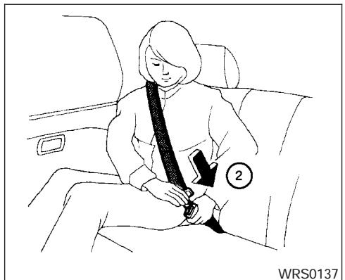
② Slowly pull the seat belt out of the retractor and insert the tongue into the buckle until you hear and feel the latch engage.
- The retractor is designed to lock during a sudden stop or on impact. A slow pulling motion permits the seat belt to move, and allows you some freedom of movement in the seat.
- If the seat belt cannot be pulled from its fully retracted position, firmly pull the belt and release it. Then smoothly pull the belt out of the retractor.
③ Position the lap belt portion low and snug on the hips as shown.
④ Pull the shoulder belt portion toward the retractor to take up extra slack. Be sure the shoulder belt is routed over your shoulder and across your chest.
The front passenger seat and the rear seating positions three-point seat belts have a locking mechanism for child restraint installation. It is referred to as the automatic locking mode or child restraint mode.
When automatic locking mechanism is activated the seat belt cannot be extended again until the seat belt tongue is detached from the buckle and
fully retracted. Once retracted, the seat belt is in the emergency locking mode. See “Child restraints” later in this section for more information.
The automatic locking mode should be used only for child restraint installation. During normal seat belt use by a passenger, the locking mode should not be activated. If it is activated it may cause uncomfortable seat belt tension. It can also change the operation of the front passenger air bag. See “Front passenger air bag and status light” later in this section.

WARNING
When fastening the seat belts, be certain that the seatbacks are completely secured in the latched position. If they are not completely secured, passengers may be injured in an accident or sudden stop.
Unfastening the seat belts
① To unfasten the seat belt, press the button on the buckle. The seat belt automatically retracts.
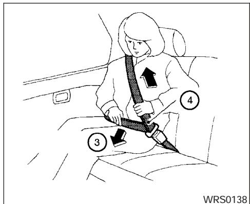
Checking seat belt operation
Seat belt retractors are designed to lock seat belt movement by two separate methods:
- When the seat belt is pulled quickly from the retractor.
- When the vehicle slows down rapidly.
To increase your confidence in the seat belts, check the operation as follows.
- Grasp the shoulder belt and pull forward quickly. The retractor should lock and restrict further belt movement.
If the retractor does not lock during this check or if you have any questions about seat belt operation, see a NISSAN dealer.
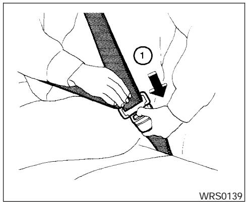
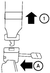
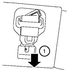
Center of the 3rd row bench seat
The 3rd row center seat belt has a connector tongue ① and a seat belt tongue ②. Both the connector tongue and the seat belt tongue must be securely latched for proper seat belt operation.
natural_image
Line drawing of a person sitting inside a vehicle seatbelt, no text or symbols presentWARNING
- Always fasten the connector tongue and the seat belt in the order shown.
- Always make sure both the connector tongue and the seat belt tongue are secured when using the seat belt. Do not use it with only the seat belt tongue attached. This could result in serious personal injury in case of an accident or a sudden stop.
LRS0432
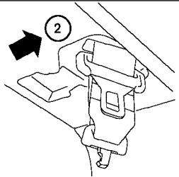
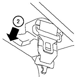
Stowing the 3rd row center seat belt
When folding down the 3rd row seat, the rear center seat belt can be retracted into a stowed position as follows:
① Release the connector tongue by inserting a suitable tool such as key into the connector buckle Ⓐ.
② Retract the seat belt up to the retractor base.
③ Insert the seat belt tongue into the fabric sleeve so it will lay flat. Then secure the connector tongue into the retractor base.
WARNING
- Do not unfasten the rear center seat belt connector except when folding down the rear seat.
- When attaching the rear center seat belt connector, be certain that the seat-backs are completely secured in the latched position and the rear center seat belt connector is completely secured.
- If the rear center seat belt connector and the seatbacks are not secured in the correct position, serious personal injury may result in an accident or sudden stop.
LRS0433
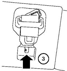
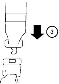
Attaching the 3rd row center seat belt
Always be sure the 3rd row center seat belt connector tongue and connector buckle are attached. Disconnect only when folding down the rear seat.
To connect the buckle:
① Pull out the connector tongue from the retractor base.
② Pull out the seat belt tongue from the fabric sleeve.
③ Pull the seat belt and secure the receiver buckle until it clicks.
The center seat belt connector tongue and receiver buckle are indicated by the > and < mark.
The center seat belt connector tongue can be attached only into the rear center seat belt connector buckle.
To fasten the seat belt, see “Fastening the seat belt” earlier in this section.

WARNING
- Do not unfasten the rear center seat belt connector except when folding down the rear seat.
- When attaching the rear center seat belt connector, be certain that the seat-backs are completely secured in the latched position and the rear center seat belt connector is completely secured.
- If the rear center seat belt connector and the seatbacks are not secured in the correct position, serious personal injury may result in an accident or sudden stop.
LRS0242
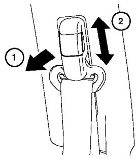
Front and 2nd row outboard seats
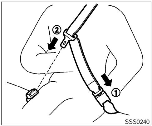
Shoulder belt height adjustment (front and 2nd row outboard seats)
The shoulder belt anchor height should be adjusted to the position best for you. (See “Precautions on seat belt usage” earlier in this section.) To adjust, pull out ① the adjustment button and move the shoulder belt anchor ② to the desired position, so the belt passes over the center of the shoulder. The belt should be away from your face and neck, but not falling off your shoulder. Release the adjustment button to lock the shoulder belt anchor into position.
WARNING
- After adjustment, release the adjustment button and try to move the shoulder belt anchor up and down to make sure it is securely fixed in position.
- The shoulder belt anchor height should be adjusted to the position best for you. Failure to do so may reduce the effectiveness of the entire restraint system and increase the chance or severity of injury in an accident.
SEAT BELT EXTENDERS
If, because of body size or driving position, it is not possible to properly fit the lap-shoulder belt and fasten it, an extender is available which is compatible with the installed seat belts. The extender adds approximately 8 inches (200 mm) of length and may be used for either the driver or front passenger seating position. See a NISSAN dealer for assistance if an extender is required.
WARNING
- Only NISSAN seat belt extenders, made by the same company which made the original equipment seat belts, should be used with NISSAN seat belts.
- Adults and children who can use the standard seat belt should not use an extender. Such unnecessary use could result in serious personal injury in the event of an accident.
- Never use seat belt extenders to install child restraints. If the child restraint is not secured properly, the child could be seriously injured in a collision or a sudden stop.
CHILD RESTRAINTS
SEAT BELT MAINTENANCE
- To clean the seat belt webbing, apply a mild soap solution or any solution recommended for cleaning upholstery or carpet. Then wipe with a cloth and allow the seat belts to dry in the shade. Do not allow the seat belts to retract until they are completely dry.
- If dirt builds up in the shoulder belt guide of the seat belt anchors, the seat belts may retract slowly. Wipe the shoulder belt guide with a clean, dry cloth.
- Periodically check to see that the seat belt and the metal components, such as buckles, tongues, retractors, flexible wires and anchors, work properly. If loose parts, deterioration, cuts or other damage on the webbing is found, the entire seat belt assembly should be replaced.
natural_image
Diagram of a car interior showing two people using a double-headed horizontal bar to tie, no text or symbols presentPRECAUTIONS ON CHILD RESTRAINTS
WARNING
- Infants and small children should always be placed in an appropriate child restraint while riding in the vehicle. Failure to use a child restraint can result in serious injury or death.

natural_image
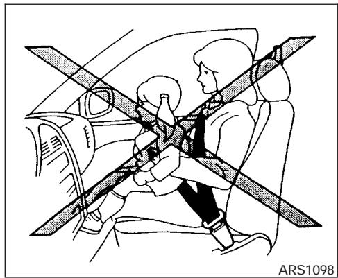
Diagram of a car showing a person seated inside the seat with a cross-shaped belt, no text or symbols present.WARNING
- Infants and small children should never be carried on your lap. It is not possible for even the strongest adult to resist the forces of a severe accident. The child could be crushed between the adult and parts of the vehicle. Also, do not put the same seat belt around both your child and yourself.
- Even with the NISSAN Advanced Air Bag System, never install a rear-facing child restraint in the front seat. An inflating supplemental front air bag could seriously injure or kill your child. A rear-facing child restraint must only be used in the rear seat.
- NISSAN recommends that the child restraint be installed in the rear seat. According to accident statistics, children are safer when properly restrained in the rear seat than in the front seat.
- An improperly installed child restraint could lead to serious injury or death in an accident.
In general, child restraints are designed to be installed with the lap portion of a lap/shoulder seat belt. In addition, this vehicle is equipped with a universal child restraint lower anchor system, referred to as the LATCH (Lower Anchors and Tethers for CHildren) system. Some child restraints include two rigid or webbing-mounted attachments that can be connected to these lower anchors. For details, see the “LATCH (Lower Anchors and Tethers for CHildren) system” later in this section.
Child restraints for infants and small children of various sizes are offered by several manufacturers. When selecting any child restraint, keep the following points in mind:
- Choose only a restraint with a label certifying that it complies with Federal Motor Vehicle Safety Standard 213 or Canadian Motor Vehicle Safety Standard 213.
- Check the child restraint in your vehicle to be sure it is compatible with the vehicle's seat and seat belt system.
- If the child restraint is compatible with your vehicle, place your child in the child restraint and check the various adjustments to be sure the child restraint is compatible with your child. Choose a child restraint that is designed for your child's height and weight. Always follow all recommended procedures.
All U.S. states and Canadian provinces or territories require that infants and small children be restrained in an approved child restraint at all times while the vehicle is being operated.

WARNING
- Improper use of a child restraint can increase the risk or severity of injury for both the child and other occupants of the vehicle.
- Follow all of the child restraint manufacturer's instructions for installation and use. When purchasing a child restraint, be sure to select one which will fit your child and vehicle. It may not be possible to properly install some types of child restraints in your vehicle.
- If the child restraint is not anchored properly, the risk of a child being injured in a collision or a sudden stop greatly increases.
- Adjustable seatbacks should be positioned to fit the child restraint, but as upright as possible.
-
After attaching the child restraint, test it before you place the child in it. Push it from side to side. Try to tug it forward and check to see if the belt holds the restraint in place. The child restraint should not move more than 1 inch (25 mm). If the restraint is not secure, tighten the belt as necessary, or put the restraint in another seat and test it again. You may need to try a different child restraint. Not all child restraints fit in all types of vehicles.
-
If you must install a front facing child restraint in the front seat, see “Child restraint installation on front passenger seat” later in this section.
- When your child restraint is not in use, keep it secured with a seat belt to prevent it from being thrown around in case of a sudden stop or accident.

CAUTION
Remember that a child restraint left in a closed vehicle can become very hot. Check the seating surface and buckles before placing your child in the child restraint.
CHILD RESTRAINT INSTALLATION ON 2ND ROW CAPTAIN'S CHAIRS

WARNING
- The three-point seat belt in your vehicle is equipped with an automatic locking mode retractor which must be used when installing a child restraint.
- Failure to use the retractor's locking mode will result in the child restraint not being properly secured. The restraint could tip over or otherwise be unsecured and cause injury to the child in a sudden stop or collision.
Front Facing — step 1
Front facing
When you install a child restraint on the 2nd row captain's chairs, follow these steps:
① Position the child restraint on the seat. Adjust the head restraint to its highest position. Always follow the restraint manufacturer's instructions. The back of the child restraint should be secured against the vehicle seat back. If necessary, adjust or remove the head restraint to obtain the correct child restraint fit. See "Head restraint adjustment" earlier in this section. If the head restraint is removed, store it in a secure place. Be sure to install the head restraint when the child restraint is removed. If the seating position does not have an adjustable head restraint and it is interfering with the proper child restraint fit, try another seating position or a different child restraint.
Front Facing — step 2
② Route the seat belt tongue through the child restraint and insert it into the buckle until you hear and feel the latch engage.
Be sure to follow the child restraint manufacturer's instructions for belt routing.
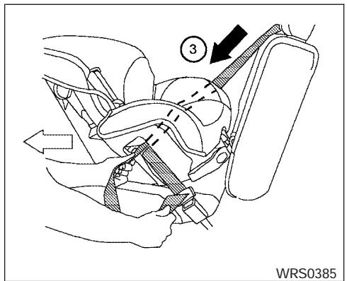
Front Facing — step 3
③ Pull on the shoulder belt until all of the belt is fully extended. At this time, the seat belt retractor is in the automatic locking mode (child restraint mode). It reverts back to emergency locking mode when the seat belt is fully retracted.

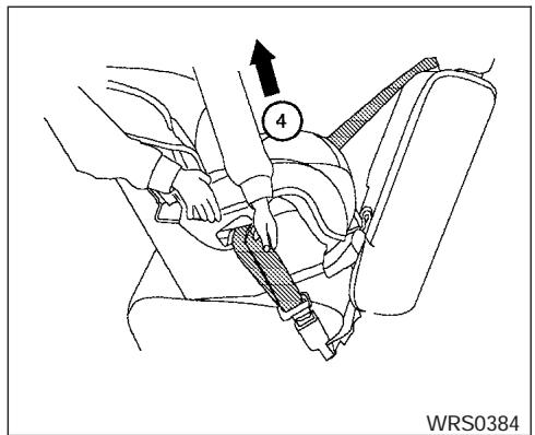
Front Facing — step 4
④ Allow the seat belt to retract. Pull up on the shoulder belt to remove any slack in the belt.

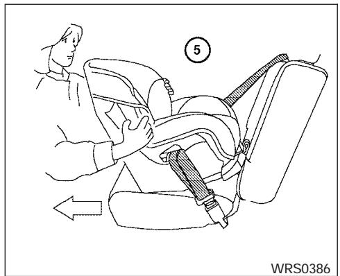
Front Facing — step 5
⑤ Before placing the child in the child restraint, use force to push the child restraint from side to side, and tug it forward to make sure that it is securely held in place. It should not move more than 1 inch (25 mm). If it does move more than 1 inch (25 mm), pull again on the shoulder belt to further tighten the child restraint. If unable to properly secure the restraint move the restraint to another rear seating position and try again, or try a different child restraint. Not all child restraints fit in all types of vehicles.
- Check that the retractor is in the automatic locking mode by trying to pull more seat belt out of the retractor. If you cannot pull any more belt webbing out of the retractor, the retractor is in the automatic locking mode.
- Check to make sure that the child restraint is properly secured prior to each use. If the belt is not locked, repeat steps 3 through 6.
After the child restraint is removed and the seat belt is fully retracted, the automatic locking mode (child restraint mode) is canceled.
Rear Facing — step 1
Rear facing
When you install a child restraint on the 2nd row captain's chair, follow these steps:
① Position the child restraint on the seat. Always follow the restraint manufacturer's instructions.
Rear Facing — step 2
② Route the seat belt tongue through the child restraint and insert it into the buckle until you hear and feel the latch engage.
Be sure to follow the child restraint manufacturer's instructions for belt routing.
Rear Facing — step 3
③ Pull on the shoulder belt until all of the belt is fully extended. At this time, the seat belt retractor is in the automatic locking mode (child restraint mode). It reverts to emergency locking mode when the seat belt is fully retracted.
Rear Facing — step 4
④ Allow the seat belt to retract. Pull up on the shoulder belt to remove any slack in the belt.
Rear Facing — step 5
⑤ Before placing the child in the child restraint, use force to push the child restraint from side to side, and tug it forward to make sure that it is securely held in place. It should not move more than 1 inch (25 mm). If it does move more than 1 inch (25 mm), pull again on the shoulder belt to further tighten the child restraint. If unable to properly secure the restraint move the restraint to another rear seating position and try again, or try a different child restraint. Not all child restraints fit in all types of vehicles.
- Check that the retractor is in the automatic locking mode by trying to pull more seat belt out of the retractor. If you cannot pull any more seat belt webbing out of the retractor, the retractor is in the automatic locking mode.
- Check to make sure that the child restraint is properly secured prior to each use. If the belt is not locked, repeat steps 3 through 6.
After the child restraint is removed and the seat belt fully retracted, the automatic locking mode (child restraint mode) is canceled.
CHILD RESTRAINT INSTALLATION ON 2ND ROW BENCH SEATS (if so equipped)
WARNING
- The three-point seat belt in your vehicle is equipped with an automatic locking mode retractor which must be used when installing a child restraint.
- Failure to use the retractor's locking mode will result in the child restraint not being properly secured. The restraint could tip over or otherwise be unsecured and cause injury to the child in a sudden stop or collision.
- When installing a child restraint system in the 2nd row center position both the center seat belt connector tongue and buckle tongue must be secured.
natural_image
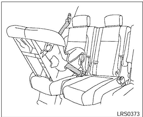
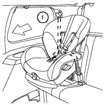
Line drawing of a car seatbelt with seat, showing no text or symbols on the diagram itselfFront facing (outboard) — step 1

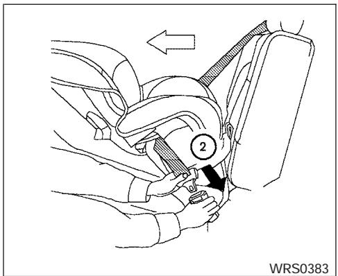
natural_image
Line drawing of a car seat assembly with no text or symbolsFront facing (center) — step 1
Front facing
When you install a child restraint on the 2nd row bench seat, follow these steps:
① Position the child restraint on the seat. Adjust the head restraint to its highest position. Always follow the restraint manufacturer's instructions. The back of the child restraint should be secured against the vehicle seat back. If necessary, adjust or remove the head restraint to obtain the correct child restraint fit. See "Head restraint adjustment" earlier in this section. If the head restraint is removed, store it in a secure place. Be sure to install the head restraint when the child restraint is removed. If the seating position does not have an adjustable head restraint and it is interfering with the proper child restraint fit, try another seating position or a different child restraint.
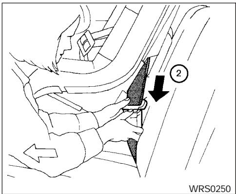
Front Facing — step 2
② Route the seat belt tongue through the child restraint and insert it into the buckle until you hear and feel the latch engage.
Be sure to follow the child restraint manufacturer's instructions for belt routing.
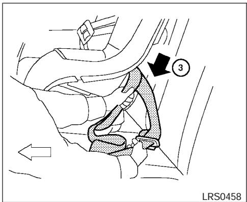
Front Facing — step 3
③ Pull on the shoulder belt until all of the belt is fully extended. At this time, the seat belt retractor is in the automatic locking mode (child restraint mode). It reverts back to emergency locking mode when the seat belt is fully retracted.
Front Facing — step 4
④ Allow the seat belt to retract. Pull up on the shoulder belt to remove any slack in the belt.

Front Facing — step 5
⑤ Before placing the child in the child restraint, use force to push the child restraint from side to side, and tug it forward to make sure that it is securely held in place. It should not move more than 1 inch (25mm). If it does move more than 1 inch (25 mm), pull again on the shoulder belt to further tighten the child restraint. If unable to properly secure the restraint move the restraint to another rear seating position and try again, or try a different child restraint. Not all child restraints fit in all types of vehicles.
- Check that the retractor is in the automatic locking mode by trying to pull more seat belt out of the retractor. If you cannot pull any more belt webbing out of the retractor, the retractor is in the automatic locking mode.
- Check to make sure that the child restraint is properly secured prior to each use. If the belt is not locked, repeat steps 3 through 6.
After the child restraint is removed and the seat belt is fully retracted, the automatic locking mode (child restraint mode) is canceled.
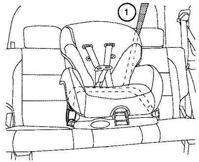
natural_image
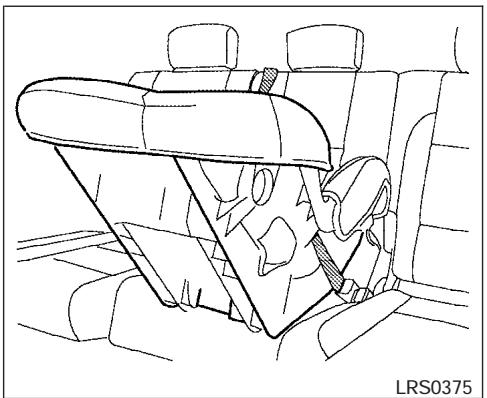
Line drawing of a car interior showing seatbelt and seatbelt (no text or symbols)Rear facing (outboard) — step 1
natural_image
Line drawing of a car interior showing seat, dashboard, and rear seats (no text or symbols)Rear facing (center) — step 1
Rear facing
When you install a child restraint on the 2nd row bench seat, follow these steps:
① Position the child restraint on the seat. Always follow the restraint manufacturer's instructions.

Rear Facing — step 2
② Route the seat belt tongue through the child restraint and insert it into the buckle until you hear and feel the latch engage.
Be sure to follow the child restraint manufacturer's instructions for belt routing.

Rear Facing — step 3
③ Pull on the shoulder belt until all of the belt is fully extended. At this time, the seat belt retractor is in the automatic locking mode (child restraint mode). It reverts to emergency locking mode when the seat belt is fully retracted.

Rear Facing — step 4
④ Allow the seat belt to retract. Pull up on the shoulder belt to remove any slack in the belt.
Rear Facing — step 5
⑤ Before placing the child in the child restraint, use force to push the child restraint from side to side, and tug it forward to make sure that it is securely held in place. It should not move more than 1 inch (25mm). If it does move more than 1 inch (25 mm), pull again on the shoulder belt to further tighten the child restraint. If unable to properly secure the restraint move the restraint to another rear seating position and try again, or try a different child restraint. Not all child restraints fit in all types of vehicles.
- Check that the retractor is in the automatic locking mode by trying to pull more seat belt out of the retractor. If you cannot pull any more seat belt webbing out of the retractor, the retractor is in the automatic locking mode.
- Check to make sure that the child restraint is properly secured prior to each use. If the belt is not locked, repeat steps 3 through 6.
After the child restraint is removed and the seat belt fully retracted, the automatic locking mode (child restraint mode) is canceled.
CHILD RESTRAINT INSTALLATION ON 3RD ROW BENCH SEAT

WARNING
- The three-point seat belt in your vehicle is equipped with an automatic locking mode retractor which must be used when installing a child restraint.
- Failure to use the retractor's locking mode will result in the child restraint not being properly secured. The restraint could tip over or otherwise be unsecured and cause injury to the child in a sudden stop or collision.
- When installing a child restraint system in the rear center position, both the center seat belt connector tongue and buckle tongue must be secured. See "Attaching rear center seat belt" earlier in this section.
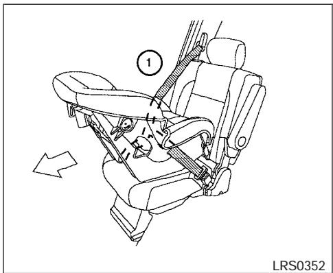
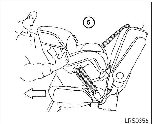
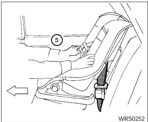
LRS0357
Front Facing (outboard) — step 1
Front facing

WARNING
Front-facing child restraints can be installed in all 3rd row bench seat positions. However, front-facing child restraints that require the use of a top tether strap can be installed in the center 3rd row position only. Do not install a child restraint requiring a top tether strap in an outboard position and attempt to angle the tether to the 3rd row center anchor.
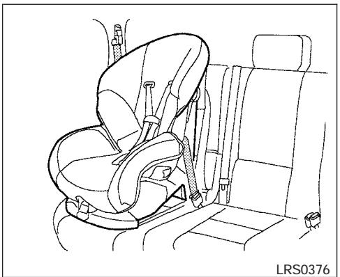
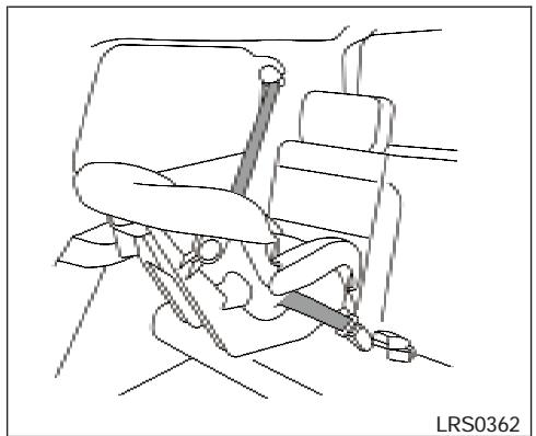
natural_image
Line drawing of a car seat assembly with no text or symbolsLRS0358
Front Facing (center) — step 1
When you install a child restraint on the 3rd row bench seat, follow these steps:
① Position the child restraint on the seat. Adjust the head restraint to its highest position. Always follow the restraint manufacturer's instructions. The back of the child restraint should be secured against the vehicle seat back. If necessary, adjust or remove the head restraint to obtain the correct child restraint fit. See "Head restraint adjustment" earlier in this section. If the head restraint is removed, store it in a secure place. Be sure to install the head restraint when the child restraint is removed. If the seating position does not have an adjustable head restraint and it is interfering with the proper child restraint fit, try another seating position or a different child restraint.
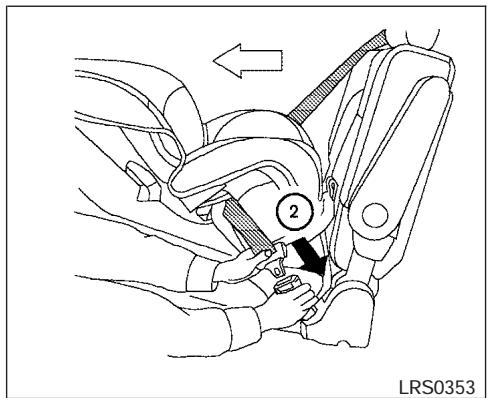
Front Facing — step 2
② Route the seat belt tongue through the child restraint and insert it into the buckle until you hear and feel the latch engage.
Be sure to follow the child restraint manufacturer's instructions for belt routing.
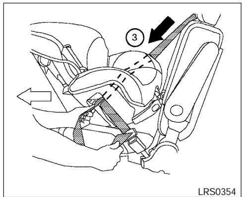
Front Facing — step 3
③ Pull on the shoulder belt until all of the belt is fully extended. At this time, the seat belt retractor is in the automatic locking mode (child restraint mode). It reverts back to emergency locking mode when the seat belt is fully retracted.

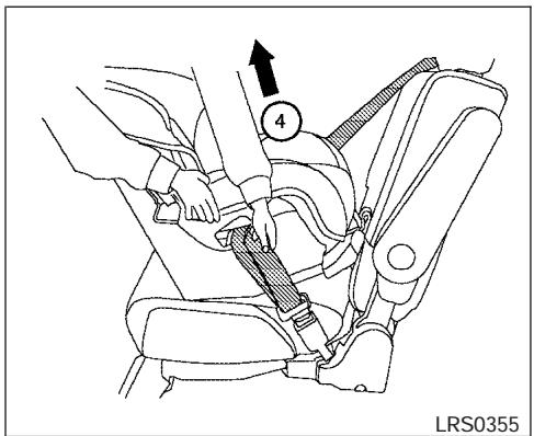
Front Facing — step 4
④ Allow the seat belt to retract. Pull up on the shoulder belt to remove any slack in the belt.
Front Facing — step 5
⑤ Before placing the child in the child restraint, use force to push the child restraint from side to side, and tug it forward to make sure that it is securely held in place. It should not move more than 1 inch (25mm). If it does move more than 1 inch (25 mm), pull again on the shoulder belt to further tighten the child restraint. If unable to properly secure the restraint move the restraint to another rear seating position and try again, or try a different child restraint. Not all child restraints fit in all types of vehicles.
- Check that the retractor is in the automatic locking mode by trying to pull more seat belt out of the retractor. If you cannot pull any more belt webbing out of the retractor, the retractor is in the automatic locking mode.
- Check to make sure that the child restraint is properly secured prior to each use. If the belt is not locked, repeat steps 3 through 6.
After the child restraint is removed and the seat belt is fully retracted, the automatic locking mode (child restraint mode) is canceled.
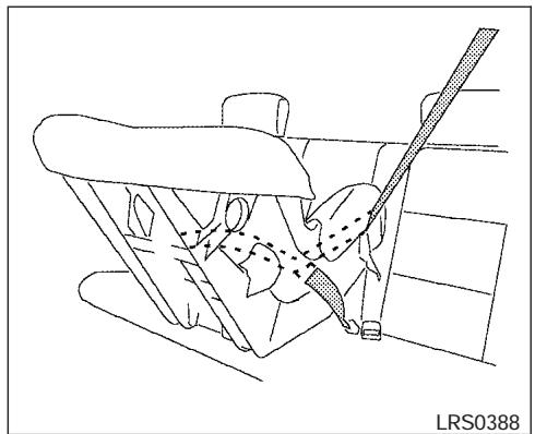
natural_image
Line drawing of a car seatbelt mechanism (no text or symbols)Rear Facing (outboard) — step 1
Rear facing
When you install a child restraint on the 3rd row bench seat, follow these steps:
① Position the child restraint on the seat. Always follow the restraint manufacturer's instructions.
natural_image
Line drawing of a car seatbelt with a belt and seatbelt, no text or symbols presentRear Facing (center) — step 1
Rear Facing — step 2
② Route the seat belt tongue through the child restraint and insert it into the buckle until you hear and feel the latch engage.
Be sure to follow the child restraint manufacturer's instructions for belt routing.
Rear Facing — step 3
③ Pull on the shoulder belt until all of the belt is fully extended. At this time, the seat belt retractor is in the automatic locking mode (child restraint mode). It reverts to emergency locking mode when the seat belt is fully retracted.
Rear Facing — step 4
④ Allow the seat belt to retract. Pull up on the shoulder belt to remove any slack in the belt.

Rear Facing — step 5
⑤ Before placing the child in the child restraint, use force to push the child restraint from side to side, and tug it forward to make sure that it is securely held in place. It should not move more than 1 inch (25mm). If it does move more than 1 inch (25 mm), pull again on the shoulder belt to further tighten the child restraint. If unable to properly secure the restraint move the restraint to another rear seating position and try again, or try a different child restraint. Not all child restraints fit in all types of vehicles.
- Check that the retractor is in the automatic locking mode by trying to pull more seat belt out of the retractor. If you cannot pull any more seat belt webbing out of the retractor, the retractor is in the automatic locking mode.
- Check to make sure that the child restraint is properly secured prior to each use. If the belt is not locked, repeat steps 3 through 6.
After the child restraint is removed and the seat belt fully retracted, the automatic locking mode (child restraint mode) is canceled.
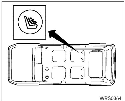
LATCH system anchor point locations 2nd row captain's chairs (if so equipped)
LATCH (Lower Anchors and Tethers for CHildren) SYSTEM
LATCH anchor point labels 2nd row captain's chairs (if so equipped)
LATCH system anchor point locations 2nd row bench seat (if so equipped)
LATCH anchor point labels 2nd row bench seat (if so equipped)
WARNING
- Attach LATCH system compatible child restraints only at the locations shown. If a child restraint is not secured properly, your child could be seriously injured or killed in an accident.
- The LATCH system anchors are designed to withstand only those loads imposed by correctly fitted child restraints. Under no circumstance are they to be used for adult seat belts or harnesses.
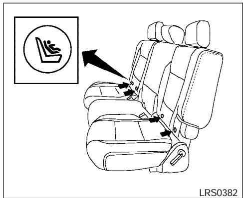
Some child restraints include two rigid or webbing-mounted attachments that can be connected to two anchors located at certain seating positions in your vehicle. This system is known as the LATCH (Lower Anchors and Tethers for CHildren) system. This system may also be referred to as the ISOFIX or ISOFIX compatible system. With this system, you do not have to use a vehicle seat belt to secure the child restraint. Your vehicle is equipped with special anchor points that are used with LATCH system compatible child restraints. Check your child restraint for a label stating that it is compatible with the LATCH system. This information may also be in the child restraint owner's manual. If you have such a child restraint, refer to the illustration for the seating positions equipped with LATCH system anchors which can be used to secure the child restraint.
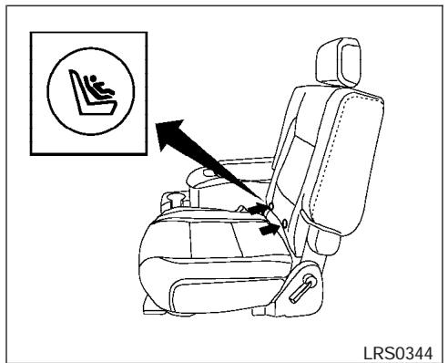
The LATCH system anchors are located at the rear of the seat cushion near the seatback. A label is attached to the seatback to help you locate the LATCH system anchors.
LATCH child restraints generally require the use of a top tether strap. See "Top tether strap child restraint" later in this section for installation instructions.
When installing a child restraint, carefully read and follow the instructions in this manual and those supplied with the child restraint.
When you install a LATCH system compatible child restraint to the lower anchor attachments, follow these steps:
WARNING
Inspect the lower anchors by inserting your fingers into the lower anchor area and feeling to make sure there are no obstructions over the LATCH system anchors, such as seat belt webbing or seat cushion material. The child restraint will not be secured properly if the LATCH system anchors are obstructed.
- To install the LATCH system compatible child restraint, insert the child restraint LATCH system anchor attachments into the anchor points on the seat. If the child restraint is equipped with a top tether, see "Top tether strap child restraint" later in this section for installation instructions.
- After attaching the child restraint and before placing the child in it, use force to push the child restraint from side to side and tug it forward to make sure that the child restraint is securely held in place. It should not move more than 1 inch (25 mm).
- Check to make sure that the child restraint is properly secured prior to each use.
TOP TETHER STRAP CHILD RESTRAINT
If your child restraint has a top tether strap, it must be secured to the anchor point provided behind its position.
WARNING
Child restraint anchor points are designed to withstand only those loads imposed by correctly fitted child restraints. Under no circumstances are they to be used for adult seat belts or harnesses.
First, secure the child restraint with the seat belt or the LATCH system (2nd row outboard seat positions only), as applicable.
For the 2nd row bench seats (if so equipped) outboard seating positions only, adjust the head restraint to its highest position and route the top tether strap between the head restraint and the top of the seatback. Secure the tether strap to the tether anchor point on the floor directly behind the seat. The center position of the 2nd row bench seat is not equipped with a top tether anchor point.
For the 2nd row captain's chairs (if so equipped), adjust the head restraint to its highest position and route the top tether strap between the head
restraint and the top of the seatback. Secure the tether strap to the tether anchor point on the floor directly behind the seat.
The center position of the 3rd row bench seat is the seating position that can use a top tether strap. The center 3rd row seat position does not have a head restraint. Position the top tether strap over the top of the seatback and secure it to the tether anchor bracket as shown later in this section. Tighten the tether strap according to the manufacturer's instructions to remove any slack.
WARNING
In the 3rd row bench seat, a child restraint with a top tether strap can only be used in the center position. Do not place in an outboard seating position and attempt to angle the tether strap to the center position.
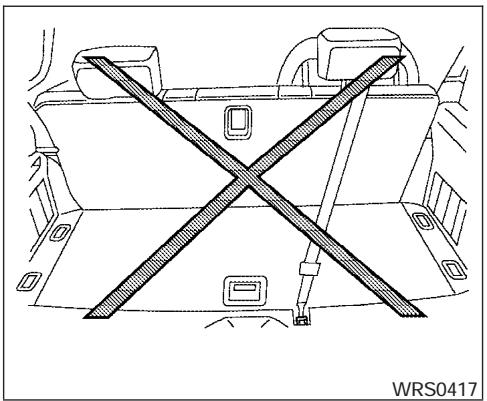
natural_image
Technical line drawing of a vehicle interior with a diagonal X-marked barrier (no text or symbols)For best child restraint fit, see the child restraint installation instructions in this section and the child restraint manufacturer's instructions.
Anchor point locations
Anchor points are located on the floor behind the outboard seating positions only for the 2nd row bench seat (if so equipped), on the floor behind the 2nd row captain's chairs (if so equipped) and on the floor of the cargo area behind the center seat position on the 3rd row bench seat as shown.
If you have any questions when installing a top strap child restraint on the rear seat, consult your NISSAN dealer for details.
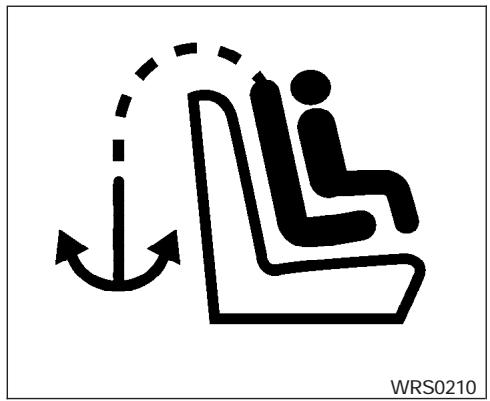
natural_image
Silhouette of a person sitting on a chair with an arrow indicating direction, no text or symbols presentLabel
Flaps are provided in the carpet for easy access to the anchor points for the 2nd row captain's chairs or 2nd row bench seats and are marked with the label shown.
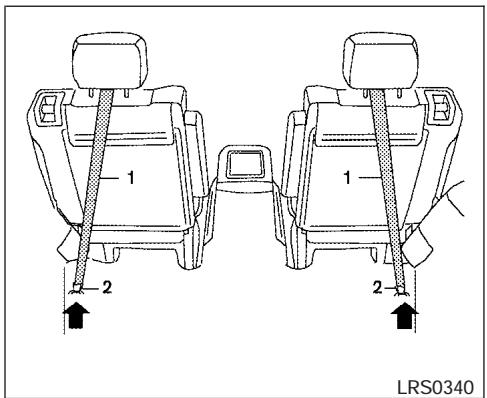
2nd row captain's chairs (if so equipped)
- Top tether strap
- Anchor point
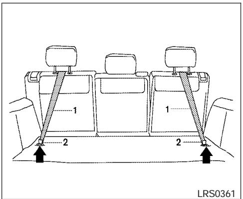
2nd row bench seat (if so equipped)
- Top tether strap
- Anchor point
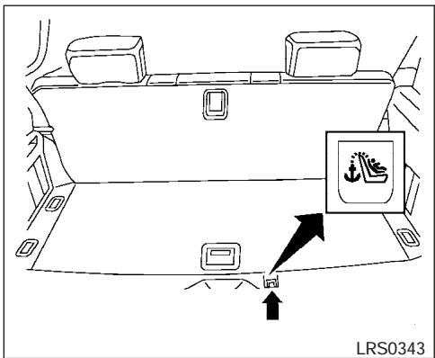
3rd row bench seat label
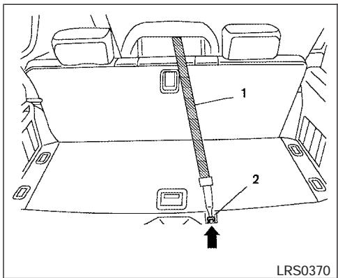
3rd row bench seat
- Top tether strap
- Anchor point
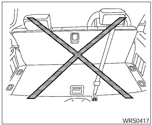
natural_image
Technical line drawing of a vehicle interior showing a cross-shaped seatbelt and dashboard (no text or symbols)
natural_image
Diagram of a car showing a person seated with a double-headed seatbelt, no text or symbols presentCHILD RESTRAINT INSTALLATION ON FRONT PASSENGER SEAT
WARNING
- Even with the NISSAN Advanced Air Bag System, never install a rear-facing child restraint in the front passenger seat. Supplemental front air bags inflate with great force. A rear-facing child restraint could be struck by the supplemental front air bag in a crash and could seriously injure or kill your child.
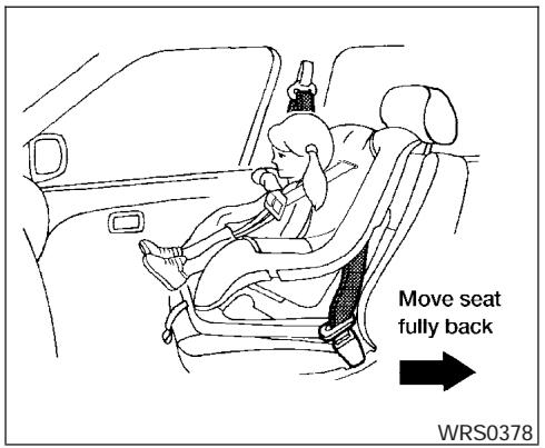
- NISSAN recommends that child restraints be installed in the rear seat. However, if you must install a forward facing child restraint in the front passenger seat, move the passenger seat to the rearmost position. Also, be sure the front passenger air bag status light is illuminated to indicate the passenger air bag is OFF. See “Front passenger air bag and status light” later in this section for details.
-
A child restraint with a top tether strap should not be used in the front passenger seat.
-
The three-point seat belt in your vehicle is equipped with an automatic locking mode retractor which must be used when installing a child restraint.
- Failure to use the retractor's locking mode will result in the child restraint not being properly secured. The restraint could tip over or otherwise be unsecured and cause injury to the child in a sudden stop or collision. Also, it can change the operation of the front passenger air bag. See "Front passenger air bag and status light" later in this section.
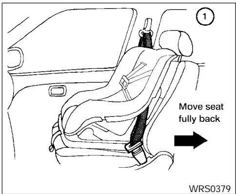
Front Facing — step 1
If you must install a child restraint in the front seat, follow these steps:
① Position the child restraint on the front pas-
senger seat. It should be placed in a
front-facing direction only. Move the
seat to the rearmost position. Adjust the
head restraint to its highest position. Always
follow the child restraint manufacturer's in-
structions. Child restraints for infants
must be used in the rear-facing direc-
tion and therefore must not be used in
the front seat.
The back of the child restraint should be secured against the vehicle seat back. If necessary, adjust or remove the head restraint to obtain the correct child restraint fit. See “Head restraint adjustment” earlier in this section. If the head restraint is removed, store it in a secure place. Be sure to install the head restraint when the child restraint is removed. If the seating position does not have an adjustable head restraint and it is interfering with the proper child restraint fit, try another seating position or a different child restraint.
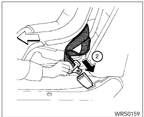
Front Facing — step 2
② Route the seat belt tongue through the child restraint and insert it into the buckle until you hear and feel the latch engage.
Be sure to follow the child restraint manufacturer's instructions for belt routing.
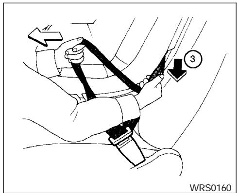
Front Facing — step 3
③ Pull on the shoulder belt until all of the belt is fully extended. At this time, the seat belt retractor is in the automatic locking mode (child restraint mode). It reverts to emergency locking mode when the seat belt is fully retracted.

Front Facing — step 4
④ Allow the seat belt to retract slightly. Pull up on the shoulder belt to remove any slack in the belt.
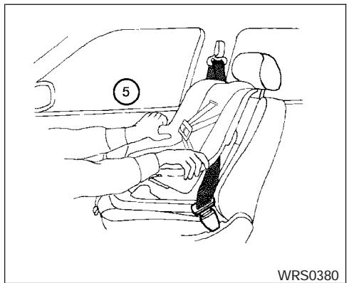
natural_image
Line drawing of a car seatbelt with a hand adjusting the seatbelt, no text or symbols presentFront Facing — step 5
⑤ Before placing the child in the child restraint, use force to push the child restraint from side to side, and tug it forward to make sure that it is securely held in place. It should not move more than 1 inch (25 mm). If it does move more than 1 inch (25 mm), pull again on the shoulder belt to further tighten the child restraint. If unable to properly secure the restraint move the restraint to another seating position and try again, or try a different child restraint. Not all child restraints fit in all types of vehicles.
- Check that the retractor is in the automatic locking mode by trying to pull more seat belt out of the retractor. If you cannot pull any more belt webbing out of the retractor, the retractor is in the automatic locking mode.
- Check to make sure the child restraint is properly secured prior to each use. If the seat belt is not locked, repeat steps 3 through 6.
- Turn the ignition to the ON position. The passenger air bag status light should say "OFF" or ×2 . If this light is not illuminated it may indicate a malfunction. Move the child restraint to another seating position. Have the system checked by a NISSAN dealer.
After the child restraint is removed and the seat belt is fully retracted, the automatic locking mode (child restraint mode) is canceled.
BOOSTER SEATS
PRECAUTIONS ON BOOSTER SEATS

WARNING
- Infants and small children should always be placed in an appropriate child restraint while riding in the vehicle. Failure to use a child restraint or booster seat can result in serious injury or death.
- Infants and small children should never be carried on your lap. It is not possible for even the strongest adult to resist the forces of a severe accident. The child could be crushed between the adult and parts of the vehicle. Also, do not put the same seat belt around both your child and yourself.
-
NISSAN recommends that the booster seat be installed in the rear seat. According to accident statistics, children are safer when properly restrained in the rear seat than in the front seat.
-
A booster seat must only be installed in a seating position that has a lap/shoulder belt. Failure to use a three-point type seat belt with a booster seat can result in a serious injury in sudden stop or collision.
- An improperly installed booster seat could lead to serious injury or death in an accident.
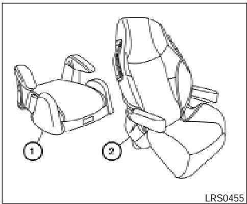
natural_image
Technical line drawing of two car seat compartments with labeled parts (1 and 2), no text or symbols present.WARNING
- Do not use towels, books, pillows or other items in place of a booster seat. Items such as these may move during normal driving or a collision and result in serious injury or death. Booster seats are designed to be used with a lap/shoulder belt. Booster seats are designed to properly route the lap and shoulder portions of the seat belt over the strongest portions of a child's body to provide the maximum protection during a collision.
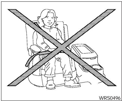
Booster seats of various sizes are offered by several manufacturers. When selecting any booster seat, keep the following points in mind:
- Choose only a booster seat with a label certifying that it complies with Federal Motor Vehicle Safety Standard 213 or Canadian Motor Vehicle Safety Standard 213.
- Check the booster seat in your vehicle to be sure it is compatible with the vehicle's seat and seat belt system.
- Make sure the child's head will be properly supported by the booster seat or vehicle seat. The seat back must be at or above the center of the child's ears. For example, if a

natural_image
Line drawing of a person sitting in a car seat with a belt, no text or symbols presentlow back booster seat ① is chosen, the vehicle seat back must be at or above the center of the child's ears. If the seat back is lower than the center of the child's ears, a high back booster seat ② should be used.
- If the booster seat is compatible with your vehicle, place your child in the booster seat and check the various adjustments to be sure the booster seat is compatible with your child. Always follow all recommended procedures.
All U.S. states and Canadian provinces or territories require that infants and small
children be restrained in an approved child restraint at all times while the vehicle is being operated.
WARNING
- Improper use of a booster seat can increase the risk or severity of injury for both the child and other occupants of the vehicle.
- Follow all of the booster seat manufacturer's instructions for installation and use. When purchasing a booster seat, be sure to select one which will fit your child and vehicle. It may not be possible to properly install some types of booster seats in your vehicle.
- If the booster seat and seat belt is not used properly, the risk of a child being injured in a collision or a sudden stop greatly increases.
-
Adjustable seatbacks should be positioned to fit the booster seat, but as upright as possible.
-
After placing the child in the booster seat and fastening the seat belt, make sure the shoulder portion of the belt is away from the child's face and neck and the lap portion of the belt does not cross the abdomen.
- Do not put the shoulder belt behind the child or under the child's arm. If you must install a booster seat in the front seat, see "Booster seat installation on front passenger seat" later in this section.
- When your booster seat is not in use, keep it secured with a seat belt to prevent it from being thrown around in case of a sudden stop or accident.
CAUTION
Remember that a booster seat left in a closed vehicle can become very hot. Check the seating surface and buckles before placing your child in the booster seat.
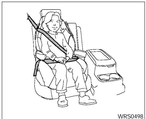
natural_image
Line drawing of a person seated in a car seat with a belt, no text or symbols presentBooster seat installation on 2nd row captain's chairs (if so equipped)
CAUTION
Do not use a lap/shoulder belt automatic locking mode when using a booster seat with the seat belts. When you install a booster seat in the rear seat follow these steps:
-
Position the booster seat on the seat. Only place it in a front facing direction. Always follow the booster seat manufacturer's instructions.
-
The booster seat should be positioned on the vehicle seat so that it is stable. If necessary, adjust or remove the head restraint to obtain the correct booster seat fit. See "Head restraint adjustment" earlier in this section. If the head restraint is removed, store it in a secure place. Be sure to install the head restraint when the booster seat is removed. If the seating position does not have an adjustable head restraint and it is interfering with the proper booster seat fit, try another seating position or a different booster seat.
- Position the lap portion of the seat belt low and snug on the child's hips. Be sure to follow the booster seat manufacturer's instructions for adjusting the belt routing.
- Pull the shoulder belt portion of the seat belt toward the retractor to take up extra slack. Be sure the shoulder belt is positioned across the top, middle portion of the child's shoulder. Be sure to follow the booster seat manufacturer's instructions for adjusting the belt routing.
- Follow the warnings, cautions and instructions for properly fastening a seat belt shown in the "Three-point seat belt with retractor" earlier in this section.
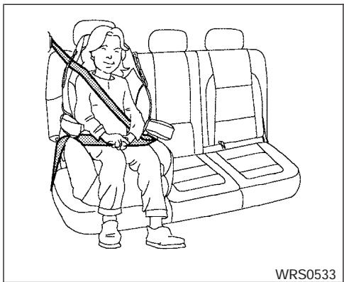
natural_image
Line drawing of a person sitting in a car seat, holding a rifle (no text or symbols)(Outboard position)
Booster seat installation on 2nd row bench seat positions (if so equipped)
CAUTION
Do not use a lap/shoulder belt automatic locking mode when using a booster seat with the seat belts. When you install a booster seat in the rear seat follow these steps:
- Position the booster seat on the seat. Only place it in a front facing direction. Always follow the booster seat manufacturer's instructions.
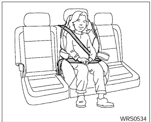
natural_image
Line drawing of a person sitting in a car seat with a seatbelt, no text or symbols present(Center position)
-
The booster seat should be positioned on the vehicle seat so that it is stable. If necessary, adjust or remove the head restraint to obtain the correct booster seat fit. See "Head restraint adjustment" earlier in this section. If the head restraint is removed, store it in a secure place. Be sure to install the head restraint when the booster seat is removed. If the seating position does not have an adjustable head restraint and it is interfering with the proper booster seat fit, try another seating position or a different booster seat.
-
Position the lap portion of the seat belt low and snug on the child's hips. Be sure to follow the booster seat manufacturer's instructions for adjusting the belt routing.
- Pull the shoulder belt portion of the seat belt toward the retractor to take up extra slack. Be sure the shoulder belt is positioned across the top, middle portion of the child's shoulder. Be sure to follow the booster seat manufacturer's instructions for adjusting the belt routing.
- Follow the warnings, cautions and instructions for properly fastening a seat belt shown in the "Three-point seat belt with retractor" earlier in this section.
- Position the lap portion of the seat belt low and snug on the child's hips. Be sure to follow the booster seat manufacturer's instructions for adjusting the belt routing.
- Pull the shoulder belt portion of the seat belt toward the retractor to take up extra slack. Be sure the shoulder belt is positioned across the top, middle portion of the child's shoulder. Be sure to follow the booster seat manufacturer's instructions for adjusting the belt routing.
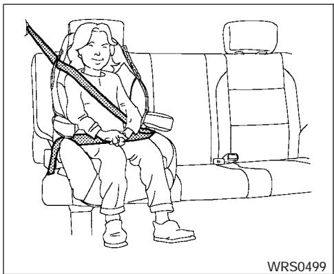
natural_image
Line drawing of a person sitting in a car seat, wearing a seatbelt and holding a long object (no text or symbols)(Outboard position)
Booster seat installation on 3rd row bench seat positions

CAUTION
Do not use a lap/shoulder belt automatic locking mode when using a booster seat with the seat belts. When you install a booster seat in the rear seat follow these steps:
- Position the booster seat on the seat. Only place it in a front facing direction. Always follow the booster seat manufacturer's instructions.
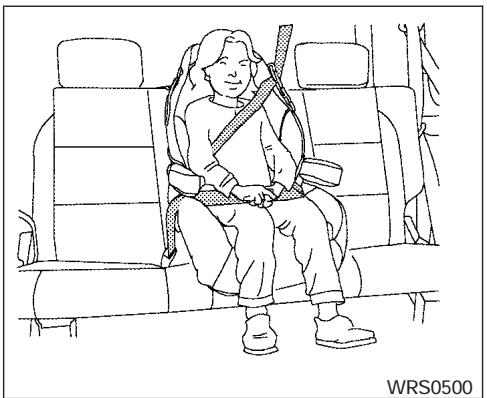
natural_image
Line drawing of a person sitting in a car seat, wearing a seatbelt and holding a vehicle (no text or symbols)(Center position)
-
The booster seat should be positioned on the vehicle seat so that it is stable. If necessary, adjust or remove the head restraint to obtain the correct booster seat fit. See "Head restraint adjustment" earlier in this section. If the head restraint is removed, store it in a secure place. Be sure to install the head restraint when the booster seat is removed. If the seating position does not have an adjustable head restraint and it is interfering with the proper booster seat fit, try another seating position or a different booster seat.
-
Position the lap portion of the seat belt low and snug on the child's hips. Be sure to follow the booster seat manufacturer's instructions for adjusting the belt routing.
- Pull the shoulder belt portion of the seat belt toward the retractor to take up extra slack. Be sure the shoulder belt is positioned across the top, middle portion of the child's shoulder. Be sure to follow the booster seat manufacturer's instructions for adjusting the belt routing.
- Follow the warnings, cautions and instructions for properly fastening a seat belt shown in the "Three-point seat belt with retractor" earlier in this section.
- Position the lap portion of the seat belt low and snug on the child's hips. Be sure to follow the booster seat manufacturer's instructions for adjusting the belt routing.
- Pull the shoulder belt portion of the seat belt toward the retractor to take up extra slack. Be sure the shoulder belt is positioned across the top, middle portion of the child's shoulder. Be sure to follow the booster seat manufacturer's instructions for adjusting the belt routing.
- Follow the warnings, cautions and instructions for properly fastening a seat belt shown in the "Three-point seat belt with retractor" earlier in this section.
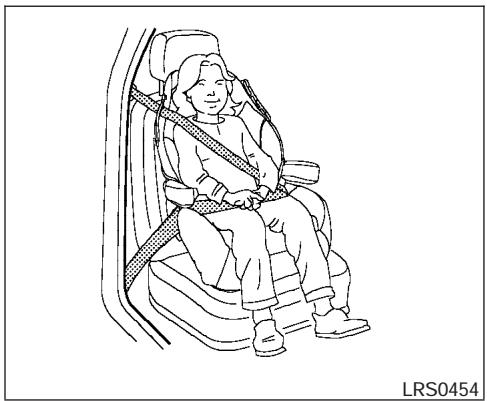
natural_image
Line drawing of a person seated in a car seat, wearing a seatbelt and holding a belt (no text or symbols)Booster seat installation on front passenger seat
WARNING
NISSAN recommends that child restraints be installed in the rear seat. However, if you must install a booster seat in the front passenger seat, move the passenger's seat to the rearmost position.
If you must install a booster seat in the front seat, follow these steps:
- Move the seat to the rear-most position.
SUPPLEMENTAL RESTRAINT SYSTEM
- Position the booster seat on the seat. Only place it in a front facing direction. Always follow the booster seat manufacturer's instructions.
- The booster seat should be positioned on the vehicle seat so that it is stable. If necessary, adjust or remove the head restraint to obtain the correct booster seat fit. See "Head restraint adjustment" earlier in this section. If the head restraint is removed, store it in a secure place. Be sure to install the head restraint when the booster seat is removed. If the seating position does not have an adjustable head restraint and it is interfering with the proper booster seat fit, try another seating position or a different booster seat.
- Position the lap portion of the seat belt low and snug on the child's hips. Be sure to follow the booster seat manufacturer's instructions for adjusting the belt routing.
-
Pull the shoulder belt portion of the seat belt toward the retractor to take up extra slack. Be sure the shoulder belt is positioned across the top, middle portion of the child's shoulder. Be sure to follow the booster seat manufacturer's instructions for adjusting the belt routing.
-
Follow the warnings, cautions and instructions for properly fastening a seat belt shown in the "Three-point seat belt with retractor" earlier in this section.
- When the ignition is turned to the ON position, the passenger air bag status light may or may not be illuminated, depending on the size of the child and the type of booster seat being used. See “NISSAN advanced air bag system” later in this section.
PRECAUTIONS ON SUPPLEMENTAL RESTRAINT SYSTEM
This Supplemental Restraint System (SRS) section contains important information concerning the driver and passenger supplemental front air bags (NISSAN Advanced Air Bag System), supplemental side air bags, curtain side-impact and rollover air bags and pre-tensioner seat belts.
Supplemental front impact air bag system: The NISSAN advanced air bag system can help cushion the impact force to the head and chest of the driver and front passenger in certain frontal collisions.
Supplemental side-impact air bag system (if so equipped): This system can help cushion the impact force to the chest area of the driver and front passenger in certain side impact collisions. The supplemental side air bag is designed to inflate on the side where the vehicle is impacted.
Supplemental curtain side-impact and roll-over air bag system: This system can help cushion the impact force to the head of occupants in front and rear outboard seating positions in certain side impact or rollover collisions. In a side impact, the curtain air bags are designed to inflate on the side where the vehicle is impacted.
In a rollover both curtain air bags are designed to inflate and remain inflated for a short time.
These supplemental restraint systems are designed to supplement the crash protection provided by the seat belts and are not a substitute for them. Seat belts should always be correctly worn and the occupant seated a suitable distance away from the steering wheel, instrument panel and door finishers. See “Seat belts” earlier in this section for instructions and precautions on seat belt usage.
The supplemental air bags operate only when the ignition switch is in the ON or START position.
After turning the ignition key to the ON position, the supplemental air bag warning light illuminates. The supplemental air bag warning light will turn off after about 7 seconds if the system is operational.
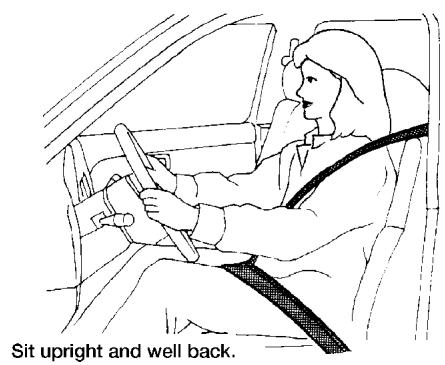
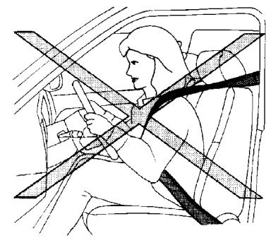
natural_image
Illustration of a person seated in a car wearing a seatbelt, crossed by a diagonal line (no text or symbols)WRS0031
WARNING
- The supplemental front air bags ordinarily will not inflate in the event of a side impact, rear impact, rollover, or lower severity frontal collision. Also, the front passenger air bag will not inflate if the passenger air bag status light is lit. See “Front passenger air bag and status light” later in this section. Always wear your seat belts to help reduce the risk or severity of injury in various kinds of accidents.
- The seat belts and the supplemental front air bags are most effective when you are sitting well back and upright in the seat. The front air bags inflate with great force. Even with the NISSAN advanced air bag system, if you are unrestrained, leaning forward, sitting sideways or out of position in any way, you are at greater risk of injury or death in a crash. You may also receive serious or fatal injuries from the supplemental front air bag if you are up against it
when it inflates. Always sit back against the seatback and as far away as practical from the steering wheel or instrument panel. Always use the seat belts.
- The driver and front passenger seat belt buckles are equipped with sensors that detect if the seat belts are fastened. The advanced air bag system monitors the severity of a collision and seat belt usage then inflates the air bags. Failure to properly wear seat belts can increase the risk or severity of injury in an accident.
- The front passenger seat is equipped with an occupant classification sensor (weight sensor) that turns the front passenger air bag OFF under some conditions. This sensor is only used in this seat. Failure to be properly seated and wearing the seat belt can increase the risk or severity of injury in an accident. See “Front Passenger air bag and status light” later in this section.
- Keep hands on the outside of the steering wheel. Placing them inside the steering wheel rim could increase the risk that they are injured when the supplemental front air bag inflates.
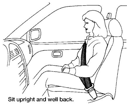
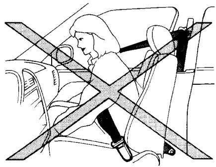
natural_image
Illustration of a person sitting in a car seatbelt with diagonal band crossing lines (no text or symbols)ARS1133
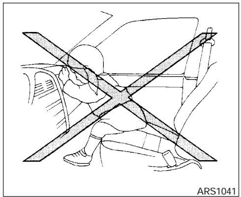
natural_image
Line drawing of a person sitting on a car with a diagonal cross symbol indicating crossed or unconnected vehicle (no text or symbols present)WARNING
- Never let children ride unrestrained or extend their hands or face out of the window. Do not attempt to hold them in your lap or arms. Some examples of dangerous riding positions are shown in the illustrations.

natural_image
Diagram of a car interior showing a person sitting on the back with a cross-shaped object between them (no text or symbols present)WARNING
- Children may be severely injured or killed when the supplemental front air bags, side air bags or curtain side-impact and rollover air bags inflate if they are not properly restrained. Pre-teens and children should be properly restrained in the rear seat, if possible.
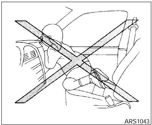
natural_image
Diagram of a car interior showing a person seated on a steering wheel, with no text or symbols present.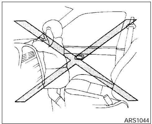
natural_image
Technical line drawing of a car seatbelt assembly (no text or symbols)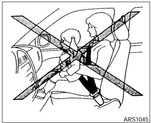
natural_image
Diagram of a car interior showing two people seated with a double-headed arrow indicating seatbelt (no text or symbols present)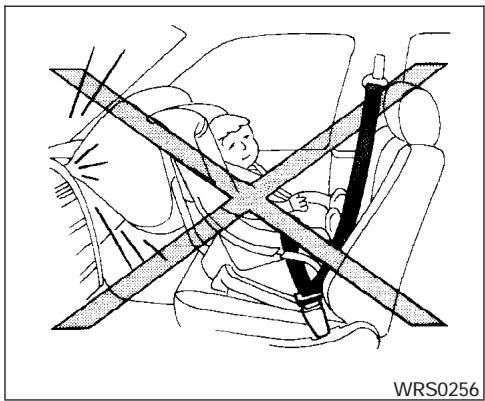
natural_image
Diagram of a car showing a person seated inside the seat with a cross-shaped belt, no text or symbols present.WARNING
- Even with the NISSAN Advanced Air Bag System, never install a rear-facing child restraint in the front seat. An inflating supplemental front air bag could seriously injure or kill your child. See "Child restraints" earlier in this section for details.
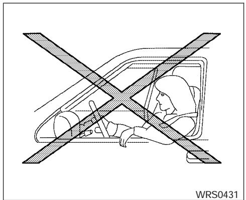
Do not lean against the door.
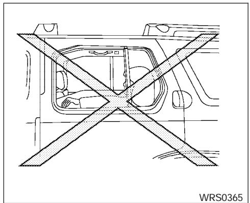
natural_image
Diagram of a vehicle interior with a cross-shaped barrier, no text or symbols presentDo not lean against doors or windows.
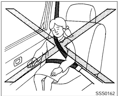
natural_image
Illustration of a person sitting in a car seat with a cross-shaped object on the seat, no text or symbols present.Do not lean against doors or windows.
WARNING
Supplemental side air bag (if so equipped) and curtain side-impact and rollover air bag:
- The supplemental side air bag and curtain side-impact and rollover air bag ordinarily will not inflate in the event of a frontal impact, rear impact, or lower severity side collision. Always wear your seat belts to help reduce the risk or severity of injury in various kinds of accidents.

WARNING
- The seat belts, the supplemental side air bags and curtain side-impact and rollover air bags are most effective when you are sitting well back and upright in the seat. The side air bag and curtain air bag inflate with great force. Do not allow anyone to place their hand, leg or face near the side air bag on the side of the seatback of the front seat or near the side roof rails. Do not allow anyone sitting in the front seats or rear outboard seats to extend their hand out of the window or lean against the door. Some examples of dangerous riding positions are shown in the previous illustrations.
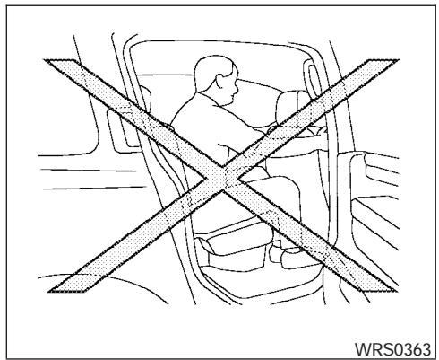
natural_image
Diagram of a person seated in a car with a cross-shaped barrier symbol (no text or labels)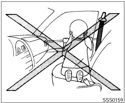
natural_image
Diagram of a car interior showing a person seated on a chair with overhead safety stripes (no text or symbols)
WARNING
- When sitting in the 2nd row rear seat, do not hold onto the seatback of the front seat. If the side air bag inflates, you may be seriously injured. Be especially careful with children, who should always be properly restrained. Some examples of dangerous riding positions are shown in the illustrations.
- Do not use seat covers on the front seatbacks. They may interfere with supplemental side air bag inflation.
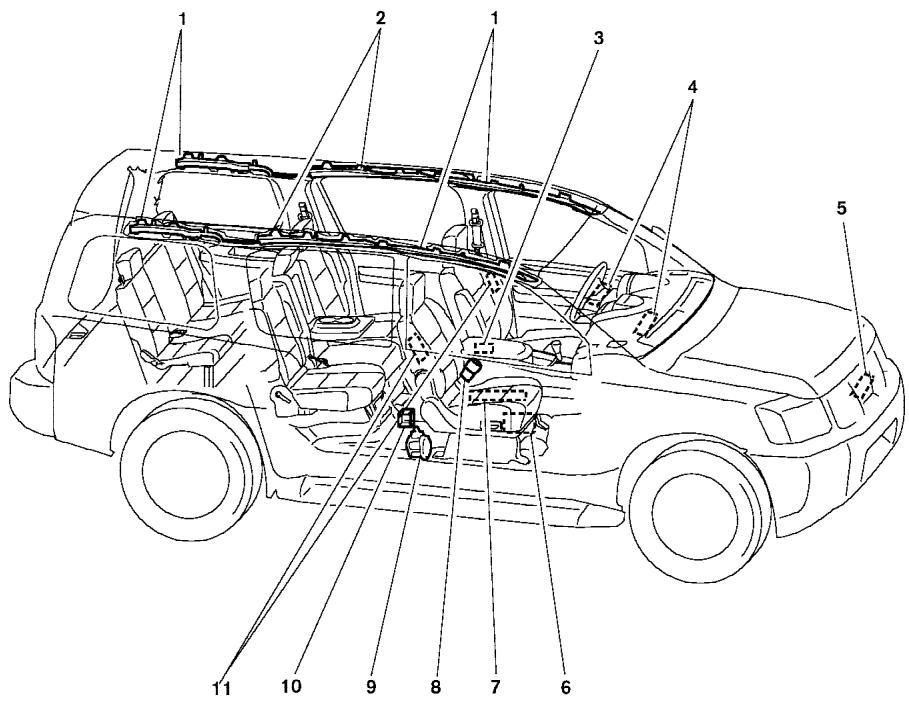
WRS0366
- SRS curtain side-impact and rollover air bag modules
- SRS curtain side-impact and rollover air bag
- Diagnosis sensor unit
- Supplemental front air bag modules
- Crash zone sensor
- Occupant classification system control unit
- Occupant classification sensor
- Seat belt buckle switches
- Pre-tensioner retractor
- Satellite sensors
- Supplemental side air bag modules (if so equipped)
NISSAN Advanced Air Bag System (front seats)
This vehicle is equipped with the NISSAN advanced air bag system for the driver and front passenger seats. This system is designed to meet certification requirements under U.S. regulations. It is also permitted in Canada. However, all of the information, cautions and warnings in this manual still apply and must be followed.
The driver supplemental front air bag is located in the center of the steering wheel. The passenger
supplemental front air bag is mounted in the dashboard above the glove box. The supplemental front air bags are designed to inflate in higher severity frontal collisions, although they may inflate if the forces in another type of collision are similar to those of a higher severity frontal impact. They may not inflate in certain frontal collisions. Vehicle damage (or lack of it) is not always an indication of proper supplemental front air bag system operation.
The NISSAN advanced air bag system has dual stage inflators. It also monitors information from the crash zone sensor, the diagnosis sensor unit, seat belt buckle sensors, occupant classification sensor (weight sensor) and passenger seat belt tension sensor. Inflator operation is based on the severity of a collision and seat belt usage for the driver. For the front passenger, it additionally monitors the weight of an occupant or object on the seat and seat belt tension. Based on information from the sensors, only one front air bag may inflate in a crash, depending on the crash severity and whether the front occupants are belted or unbelted. Additionally, the front passenger air bag may be automatically turned OFF under some conditions, depending on the weight detected on the passenger seat and how the seat belt is used. If the front passenger air bag is OFF, the passenger air bag status light will be illuminated. See “Front passenger air bag and status "light" later in this section for further details. One front air bag inflating does not indicate improper performance of the system.
If you have any questions about your air bag system, please contact NISSAN or your NISSAN dealer. If you are considering modification of your vehicle due to a disability, you may also contact NISSAN. Contact information is contained in the front of this Owner's Manual.
When a supplemental front air bag inflates, a fairly loud noise may be heard, followed by the release of smoke. This smoke is not harmful and does not indicate a fire. Care should be taken to not inhale it, as it may cause irritation and choking. Those with a history of a breathing condition should get fresh air promptly.
Supplemental front air bags, along with the use of seat belts, help to cushion the impact force on the face and chest of the front occupants. They can help save lives and reduce serious injuries. However, an inflating front air bag may cause facial abrasions or other injuries. Front air bags do not provide restraint to the lower body.
Even with NISSAN advanced air bags, seat belts should be correctly worn and the driver and passenger seated upright as far as practical away from the steering wheel or instrument panel. The supplemental front air bags inflate quickly in order to help protect the front occupants. Because of this, the force of the front air bag inflating can increase the risk of injury if the occupant is too close to, or is against, the front air bag module during inflation.
The front air bags deflate quickly after a collision.
The supplemental front air bags operate only when the ignition switch is in the ON or START position.
After turning the ignition key to the ON position, the supplemental air bag warning light illuminates. The supplemental air bag warning light will turn off after about 7 seconds if the system is operational.
LRS0351
Front passenger air bag and status light

WARNING
The front passenger air bag is designed to automatically turn OFF under some conditions. Read this section carefully to learn how it operates. Proper use of the seat, seat belt and child restraints is necessary for most effective protection. Failure to follow all instructions in this manual concerning the use of seats, seat belts and child restraints can increase the risk or severity of injury in an accident.
natural_image
Symbolic pictogram of a person running with a cross mark and number 2, no text or numbers presentLRS0316
Status light
The front passenger air bag status light OFF or 2 is located under the climate controls. The light operates as follows:
- Unoccupied passenger seat or when other conditions are met as outlined in this section: The OFF or ×2 illuminates to indicate that the front passenger air bag is OFF and will not inflate in a crash.
- Occupied passenger seat and the passenger meets the conditions outlined in this section: The light OFF or ✉2 is OFF to indicate that the front passenger air bag is operational.
Front passenger air bag
The front passenger air bag is designed to automatically turn OFF when the vehicle is operated under some conditions as described below in accordance with U.S. regulations. If the front passenger air bag is OFF, it will not inflate in a crash. The driver air bag and other air bags in your vehicle are not part of this system.
The purpose of the regulation is to help reduce the risk of injury or death from an inflating air bag to certain front passenger seat occupants, such as children, by requiring the air bag to be automatically turned OFF. Certain sensors are used to meet the requirements.
One sensor used is the occupant classification sensor (weight sensor). It is in the bottom of the front passenger seat cushion and is designed to detect an occupant and objects on the seat by weight. It works together with seat belt sensors described later. For example, if a child is in the front passenger seat, the advanced air bag system is designed to turn the passenger air bag OFF in accordance with the regulations. Also, if a child restraint of the type specified in the regulations is on the seat, its weight and the child's weight can be detected and cause the air bag to turn OFF. Weight sensor operation can vary depending on the front passenger seat belt sensors.
The front passenger seat belt sensors are designed to detect if the seat belt is buckled and the amount of tension on the seat belt, such as when it is in the automatic locking mode (child restraint mode). Based on the weight on the seat detected by the weight sensor and the belt tension detected on the seat belt, the advanced air bag system determines whether the front passenger air bag should be automatically turned OFF as required by the regulations.
Front passenger seat adult occupants who are properly seated and using the seat belt as outlined in this manual should not cause the passenger air bag to be automatically turned OFF. For small adults it may be turned OFF. Also, if the occupant takes his/her weight off the seat cushion (for example, by not sitting upright, by sitting on an edge of the seat, or by otherwise being out of position), this could cause the sensor to turn the air bag OFF. In addition, if the occupant improperly uses the seat belt in the automatic locking mode (child restraint mode), this could cause the air bag to be turned OFF. Always be sure to be seated and wearing the seat belt properly for the most effective protection by the seat belt and supplemental air bag.
NISSAN recommends that pre-teens and children be properly restrained in a rear seat. NISSAN also recommends that appropriate child restraints and booster seats be properly installed in a rear seat. If this is not possible, the weight sensor and seat belt sensors are designed to operate as described above to turn the front passenger air bag OFF for specified child restraints as required by the regulations. Failing to properly secure child restraints and to use the automatic locking mode (child restraint mode) may allow the restraint to tip or move in an accident or sudden stop. This can also result in the passenger air bag inflating in a crash instead of being OFF. See “Child restraints” earlier in this section for proper use and installation.
If the front passenger seat is not occupied and the seat belt is not buckled, the passenger air bag is designed not to inflate in a crash. However, heavy objects placed on the seat could result in air bag inflation, because of the object's weight detected by the weight sensor. Other conditions could also result in air bag inflation, such as if a child is standing on the seat, or if two children are on the seat, contrary to the instructions in this manual. Always be sure that you and all vehicle occupants are seated and restrained properly.
Using the passenger air bag status light, you can monitor when the front passenger air bag is automatically turned OFF. The light will illuminate (indicating the air bag is OFF and will not inflate) when the front passenger seat is not occupied. If an adult occupant is in the seat and the passenger air bag status light is illuminated (indicating that the air bag is OFF), it could be that the person is a small adult, or is not sitting on the seat or not using the seat belt properly. If a child restraint must be used in the front seat, but the status light is not lit (indicating that the air bag might inflate in a crash), it could be that the child restraint or seat belt is not being used properly. If such situations happen, properly position and restrain the occupant or child restraint. Otherwise reposition the occupant or child restraint in a rear seat.
If a malfunction occurs in the front passenger air bag system, the supplemental air bag warning light 🔍, located in the meter and gauges area in the center of the instrument panel, will blink. Have the system checked by a NISSAN dealer.
Other supplemental front air bag precautions
WARNING
- Do not place any objects on the steering wheel pad or on the instrument panel. Also, do not place any objects between any occupant and the steering wheel or instrument panel. Such objects may become dangerous projectiles and cause injury if the supplemental front air bag inflates.
- Immediately after inflation, several front air bag system components will be hot. Do not touch them; you may severely burn yourself.
- No unauthorized changes should be made to any components or wiring of the supplemental air bag system. This is to prevent accidental inflation of the supplemental air bag or damage to the supplemental air bag system.
-
Do not make unauthorized changes to your vehicle's electrical system, suspension system or front end structure. This could affect proper operation of the supplemental front air bag system.
-
Tampering with the supplemental front air bag system may result in serious personal injury. Tampering includes changes to the steering wheel and the instrument panel assembly by placing material over the steering wheel pad and above the instrument panel or by installing additional trim material around the air bag system.
- Modifying or tampering with the front passenger seat may result in serious personal injury. For example, do not change the front seats by placing material on the seat cushion or by installing additional trim material, such as seat covers, on the seat that are not specifically designed to assure proper air bag operation. Additionally, do not stow any objects under the front passenger seat or the seat cushion and seatback. Such objects may interfere with the proper operation of the occupant classification system (weight sensor).
- No unauthorized changes should be made to any components or wiring of the seat belt system. This may affect the supplemental front air bag system. Tampering with the seat belt system may result in serious personal injury.
- Work on and around the supplemental front air bag system should be done by a NISSAN dealer. Installation of electrical equipment should also be done by a NISSAN dealer. The Supplemental Restraint System (SRS) wiring should not be modified or disconnected. Unauthorized electrical test equipment and probing devices should not be used on the air bag system.
- A cracked windshield should be replaced immediately by a qualified repair facility. A cracked windshield could affect the function of the supplemental air bag system.
- The SRS wiring harness connectors are yellow and orange for easy identification.
When selling your vehicle, we request that you inform the buyer about the supplemental front air bag system and guide the buyer to the appropriate sections in this Owner's Manual.
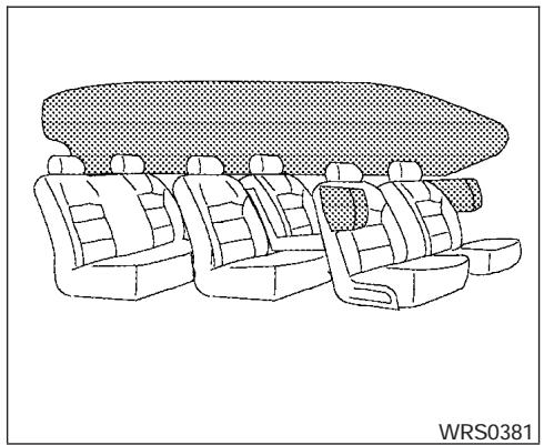
natural_image
Line drawing of a car interior with three seats and a patterned back cover (no text or symbols)Supplemental side-impact air bag (if so equipped) and curtain side-impact and rollover air bags system
The supplemental side-impact air bags are located in the outside of the seatback of the front seats. The supplemental curtain side-impact and rollover air bags are located in the side roof rails in all 3 rows. These systems are designed to meet voluntary guidelines to help reduce the risk of injury to out-of-position occupants. However, all of the information, cautions and warnings in this manual still apply and must be followed. The supplemental side air bags and curtain side-impact and rollover air bags are designed to inflate in higher severity side collisions, although they may inflate if the forces in another type of collision are similar to those of a higher severity side impact. They are designed to inflate on the side where the vehicle is impacted. They may not inflate in certain side collisions.
Curtain side-impact and rollover air bags are also designed to inflate in certain types of rollover collisions or near rollovers.
Vehicle damage (or lack of it) is not always an indication of proper supplemental side air bag and curtain side-impact and rollover air bag operation.
When the supplemental side air bag and curtain air bags inflate, a fairly loud noise may be heard, followed by release of smoke. This smoke is not harmful and does not indicate a fire. Care should be taken not to inhale it, as it may cause irritation and choking. Those with a history of a breathing condition should get fresh air promptly.
Supplemental side air bags, along with the use of seat belts, help to cushion the impact force on the chest of the front occupants. Curtain side-impact and rollover air bags help to cushion the impact force to the head of occupants in the front and rear outboard seating positions in all rows. They can help save lives and reduce serious injuries. However, an inflating side air bag, or curtain air bag may cause abrasions or other injuries. Supplemental side air bags and curtain side-impact and rollover air bags do not provide restraint to the lower body.
The seat belts should be correctly worn and the driver and passenger seated upright as far as practical away from the supplemental side air bag. Rear seat passengers should be seated as far away as practical from the door finishers and side roof rails. The side air bags and curtain air bag inflate quickly in order to help protect the occupants. Because of this, the force of the side air bag and curtain air bag inflating can increase the risk of injury if the occupant is too close to, or is against, these air bag modules during inflation. The side air bag will deflate quickly after the collision is over.
The curtain side-impact and rollover air bag will remain inflated for a short time.
The supplemental side air bags and curtain side-impact and rollover air bags operate only when the ignition switch is in the ON or START positions.
After turning the ignition key to the ON position, the supplemental air bag warning light illuminates. The supplemental air bag warning light will turn off after about 7 seconds if the system is operational.
WARNING
- Do not place any objects near the seat-back of the front seats. Also, do not place any objects (an umbrella, bag, etc.) between the front door finisher and the front seat. Such objects may become dangerous projectiles and cause injury if the supplemental side air bag inflates.
- Right after inflation, several side air bag and curtain side-impact and rollover air bag system components will be hot. Do not touch them; you may severely burn yourself.
- No unauthorized changes should be made to any components or wiring of the side air bag and curtain air bag system. This is to prevent accidental inflation of the side air bag and curtain air bag or damage to the side air bag and curtain air bag system.
-
Do not make unauthorized changes to your vehicle's electrical system, suspension system or side panel. This could affect proper operation of the supplemental curtain air bag system.
-
Tampering with the supplemental side air bag system may result in serious personal injury. For example, do not change the front seats by placing material near the seatbacks or by installing additional trim material, such as seat covers, around the side air bag.
- Work around and on the curtain air bag system should be done by a NISSAN dealer. Installation of electrical equipment should also be done by a NISSAN dealer. The SRS wiring harnesses* should not be modified or disconnected. Unauthorized electrical test equipment and probing devices should not be used on the side air bag or curtain air bag system.
* The SRS wiring harness or connectors are yellow or orange for easy identification.
When selling your vehicle, we request that you inform the buyer about the supplemental side air bag and curtain air bag system and guide the buyer to the appropriate sections in this Owner's Manual.
Pre-tensioner seat belt system (Front seats)
WARNING
- The pre-tensioner seat belt cannot be reused after activation. It must be replaced together with the retractor and buckle as a unit.
- If the vehicle becomes involved in a frontal collision but the pre-tensioner is not activated, be sure to have the pre-tensioner system checked and, if necessary, replaced by your NISSAN dealer.
-
No unauthorized changes should be made to any components or wiring of the pre-tensioner seat belt system. This is to prevent accidental activation of the pre-tensioner seat belt or damage to the pre-tensioner seat belt operation. Tampering with the pre-tensioner seat belt system may result in serious personal injury.
-
Work around and on the pre-tensioner system should be done by a NISSAN dealer. Installation of electrical equipment should also be done by a NISSAN dealer. Unauthorized electrical test equipment and probing devices should not be used on the pre-tensioner seat belt system.
- If you need to dispose of the pre-tensioner or scrap the vehicle, contact a NISSAN dealer. Correct pre-tensioner disposal procedures are set forth in the appropriate NISSAN Service Manual. Incorrect disposal procedures could cause personal injury.
The front seat pre-tensioner seat belt system activates in conjunction with the front supplemental air bag systems. Working with the seat belt retractor, it helps tighten the seat belt when the vehicle becomes involved in certain types of collisions, helping to restrain front seat occupants.
The pre-tensioner is encased with the seat belt's retractor. These seat belts are used the same as conventional seat belts.
When the pre-tensioner seat belt activates, smoke is released and a loud noise may be heard. This smoke is not harmful and does not indicate a
fire. Care should be taken not to inhale it, as it may cause irritation and choking. Those with a history of a breathing condition should get fresh air promptly.
After the pre-tensioner seat belts have activated, load limiters allow the seat belt to release webbing (if necessary) to reduce forces against the chest.
If any abnormality occurs in the pre-tensioner system, the supplemental air bag warning light 🎩 will not come on, will flash intermittently or will turn on for 7 seconds and remain on after the ignition key has been turned to the ON or START position. In this case, the pre-tensioner seat belt may not function properly. They must be checked and repaired. Take your vehicle to the nearest NISSAN dealer.
When selling your vehicle, we request that you inform the buyer about the pre-tensioner seat belt system and guide the buyer to the appropriate sections in this Owner's Manual.
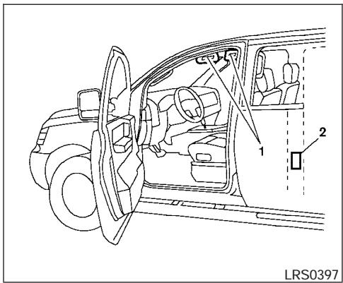
- SRS Air bag warning labels
The warning labels are located on the surface of the sun visor. - SRS Side air bag warning label (if so equipped)
The warning label is located on the side of the passenger's side center pillar.
SUPPLEMENTAL AIR BAG WARNING LABELS
Warning labels about the supplemental front air bags and supplemental side-impact and rollover air bag systems are placed in the vehicle as shown in the illustration.

natural_image
Abstract black-and-white icon of two stylized human figures in dynamic poses (no text or symbols)LRS0100
SUPPLEMENTAL AIR BAG WARNING LIGHT
The supplemental air bag warning light, displaying ⚙ in the instrument panel, monitors the circuits of the supplemental front air bag, supplemental side-impact air bag and curtain side-impact and rollover air bag and pretensioner seat belt systems. The circuits monitored by the supplemental air bag warning light are the diagnosis sensor unit, crash zone sensor, satellite sensors, rollover sensor, front air bag modules, side air bag modules, curtain air bag modules, pre-tensioner seat belts and all related wiring.
When the ignition key is in the ON or START position, the supplemental air bag warning light illuminates for about 7 seconds and then turns off. This means the system is operational.
If any of the following conditions occur, the supplemental front air bag, supplemental side air bag, curtain air bag and pre-tensioner seat belt systems need servicing:
- The supplemental air bag warning light remains on after approximately 7 seconds.
- The supplemental air bag warning light flashes intermittently.
- The supplemental air bag warning light does not come on at all.
Under these conditions, the supplemental front air bag, supplemental side air bags and curtain air bag or pre-tensioner seat belt systems may not operate properly. It must be checked and repaired. Take your vehicle to the nearest NISSAN dealer.
WARNING
If the supplemental air bag warning light is on, it could mean that the supplemental front air bag, supplemental side air bag, curtain air bag systems and/or pretensioner seat belt systems will not operate in an accident. To help avoid injury to yourself or others, have your vehicle checked by a NISSAN dealer as soon as possible.
Repair and replacement procedure
The supplemental front air bags, supplemental side air bags, curtain air bags and pre-tensioner seat belts are designed to inflate on a one-time-only basis. As a reminder, unless it is damaged, the supplemental air bag warning light remains illuminated after inflation has occurred. Repair and replacement of these supplemental air bag systems should be done only by a NISSAN dealer.
When maintenance work is required on the vehicle, the supplemental front air bags, supplemental side air bags, curtain air bags, pretensioner seat belts and related parts should be pointed out to the person performing the maintenance. The ignition key should always be in the LOCK position when working under the hood or inside the vehicle.

WARNING
- Once a supplemental front air bag, supplemental side air bag or curtain air bag has inflated, the air bag module will not function again and must be replaced. Additionally, if any of the supplemental front air bags inflate, the activated pre-tensioner seat belts must also be replaced. The air bag module and pre-tensioner seat belt system should be replaced by a NISSAN dealer. The air bag module and pre-tensioner seat belt system cannot be repaired.
- The supplemental front air bag, side air bag and curtain air bag systems, and the pre-tensioner seat belt system should be inspected by a NISSAN dealer if there is any damage to the front end or side portion of the vehicle.
- If you need to dispose of the supplemental air bag, pre-tensioner seat belt system or scrap the vehicle, contact a NISSAN dealer. Correct supplemental air bag and pre-tensioner seat belt system disposal procedures are set forth in the appropriate NISSAN Service Manual. Incorrect disposal procedures could cause personal injury.
MEMO
2 Instruments and controls
Instrument panel....2-2
Meters and gauges 2-3
Speedometer and odometer 2-4
Tachometer 2-5
Engine coolant temperature gauge 2-5
Fuel gauge 2-6
Engine oil pressure gauge 2-6
Voltmeter 2-7
Automatic transmission fluid temperature gauge (if so equipped) 2-7
Compass and outside temperature display ..... 2-8
Outside temperature display 2-8
Compass display 2-9
Warning/indicator lights and audible reminders .....2-12
Checking bulbs 2-12
Warning lights 2-13
Indicator lights 2-17
Audible reminders 2-19
Security systems 2-20
Vehicle security system....2-20
Nissan vehicle immobilizer system (NVIS) .....2-21
Windshield wiper and washer switch 2-22
Switch operation 2-22
Rear window wiper and washer switch....2-23
Rear window and outside mirror defroster switch.....2-24
Headlight and turn signal switch....2-24
Headlight control switch....2-24
Daytime running light system (Canada only) .....2-26
Instrument brightness control 2-27
Turn signal switch 2-27
Fog light switch (if so equipped) 2-28
Hazard warning flasher switch 2-28
Horn 2-29
Heated seat (if so equipped)....2-29
Vehicle dynamic control (VDC) off switch.....2-30
Rear sonar system off switch (if so equipped).....2-30
Tow mode switch....2-31
Power outlet 2-31
Cigarette lighter 2-32
Storage 2-33
Instrument panel storage trays 2-33
Console box 2-34
Glove box 2-35
Sunglasses holder....2-35
Map pockets....2-36
Seatback pocket 2-36
Overhead console....2-37
Cup holders 2-38
2nd row center console (if so equipped) .....2-40
Cargo area storage bin....2-41
Luggage hooks....2-42
Cargo net 2-43
Roof rack....2-44
Windows....2-45
Power windows 2-45
Power vent windows (if so equipped) .....2-47
Manual vent windows (if so equipped) .....2-48
Sunroof (if so equipped)....2-48
Automatic sunroof 2-48
Interior light....2-50
Console light. 2-51
Personal lights 2-51
Map lights 2-51
Cargo light 2-52
HomeLink® universal transceiver 2-52
Programming HomeLink ® 2-53
Programming HomeLink® for Canadian customers 2-54
Operating the HomeLink® universal transceiver....2-55
Programming trouble-diagnosis .....2-55
Clearing the programmed information....2-55
Reprogramming a single HomeLink® button .....2-55
If your vehicle is stolen 2-55

- Ventilators (P. 4-14)
- Instrument brightness control (P. 2-27)
- Headlight/fog light (if so equipped)/turn signal switch (P. 2-24)
- Steering wheel switch for audio control (P. 4-37)
- Driver supplemental air bag/horn (P. 1-56, P. 2-29)
- Meters, gauges and warning/indicator lights (P. 2-3, 2-12)
- Cruise control main/set switches (P. 5-14)
- Windshield wiper/washer switch and rear window wiper/washer switch (P. 2-22, P. 2-23)
- Ignition switch (P. 5-7)
- Navigation system* (if so equipped) (P. 4-2)
- Navigation system* controls (if so equipped) (P. 4-2)
- Audio system controls (P. 4-28, 4-31)
- Front passenger supplemental air bag (P. 1-56)
- Glove box (P. 2-35)
- Climate controls (P. 4-15, 4-24)
- Aux jack (if so equipped) (P. 4-36)
METERS AND GAUGES
- Heated seat switch (if so equipped) (P. 2-29)
- Power outlet/cigarette lighter (accessory) (P. 2-31/P. 2-32)
- Vehicle dynamic control (VDC) off switch (P. 2-30)
- Tow mode switch (P. 2-31)
- Shift selector lever (P. 5-9)
- Power outlet (P. 2-31)
- Front passenger air bag status light (P. 1-65)
- Hazard lights (P. 2-28)
- 4WD shift switch (if so equipped) (P. 5-17)
- Tilt steering wheel control (P. 3-16)
- Rear sonar system off switch (if so equipped) (P. 2-30)
- Pedal position adjustment switch (P. 3-16)
- Back door open/close switch (if so equipped) (P. 3-9)
*: Refer to the separate Navigation System Owner's Manual (if so equipped).
See the page number indicated in parentheses for operating details.
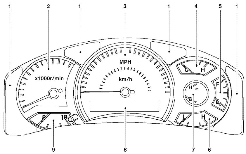
LIC0540
- Warning/indicator lights
- Tachometer
- Speedometer
- Engine coolant temperature gauge
- Fuel gauge
-
Engine oil pressure gauge
-
Automatic transmission fluid temperature gauge (if so equipped)
- Odometer/Twin trip odometer
- Voltmeter
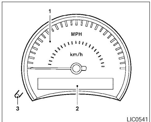
- Speedometer
- Odometer/twin trip display
- Change button
SPEEDOMETER AND ODOMETER
Speedometer
The speedometer indicates vehicle speed in miles per hour (MPH) and kilometers per hour (km/h).
Odometer/Twin trip odometer
The odometer/twin trip odometer is displayed when the ignition key is in the ON position.
The odometer records the total distance the vehicle has been driven.
The twin trip odometer records the distance of individual trips.
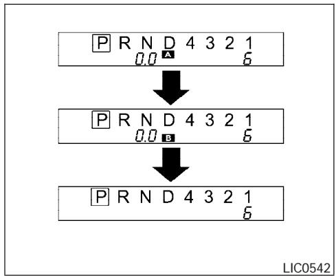
flowchart
graph TD
    A["PRND 4 3 2 1\n0.0"] --> B["PRND 4 3 2 1\n0.0"]
    B --> C["PRND 4 3 2 1\n6"]
Changing the display:
Pushing the change button changes the display as follows:
Trip □ A → Trip □ B → Odometer only
Resetting the trip odometer:
Pushing the change button for more than 1 second resets the trip odometer to zero.
Elapsed time, driving distance and average speed information is also available for vehicles with navigation system (if so equipped). Refer to "Control panel buttons" in the "Display screen, heater, air conditioner and audio systems" section later in this manual.
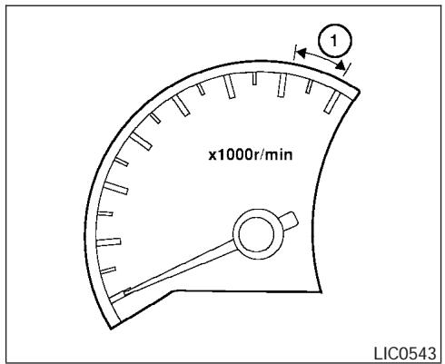
TACHOMETER
The tachometer indicates engine speed in revolutions per minute (rpm). Do not rev engine into the red zone ①.

CAUTION
When engine speed approaches the red zone, shift to a higher gear. Operating the engine in the red zone may cause serious engine damage.
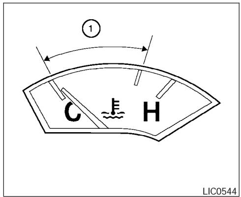
ENGINE COOLANT TEMPERATURE GAUGE
The gauge indicates the engine coolant temperature. The engine coolant temperature is within the normal range ① when the gauge needle points within the zone shown in the illustration.
The engine coolant temperature varies with the outside air temperature and driving conditions.

CAUTION
If the gauge indicates coolant temperature near the hot (H) end of the normal range, reduce vehicle speed to decrease temperature. If the gauge is over the normal range, stop the vehicle as soon as safely possible. If the engine is overheated, continued operation of the vehicle may seriously damage the engine. See "If your vehicle overheats" in the "In case of emergency" section for immediate action required.
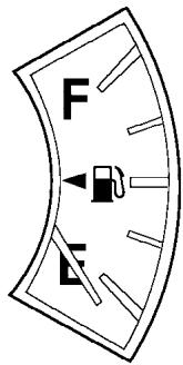
LIC0545
FUEL GAUGE
The gauge indicates the approximate fuel level in the tank.
The gauge may move slightly during braking, turning, acceleration, or going up or down hills.
The gauge needle returns to E (Empty) after the ignition key is turned to OFF.
The low fuel warning light comes on when the amount of fuel in the tank is getting low.
Refill the fuel tank before the gauge registers E (Empty).
The ◀ indicates that the fuel filler lid is located on the driver's side of the vehicle.
CAUTION
- If the vehicle runs out of fuel, the SERVICE ENGINE malfunction indicator lamp (MIL) may come on. Refuel as soon as possible. After a few driving trips, the SERVICE ENGINE lamp should turn off. If the lamp remains on after a few driving trips, have the vehicle inspected by a NISSAN dealer.
- For additional information, see “Malfunction indicator lamp (MIL)” later in this section.
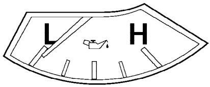
LIC0546
ENGINE OIL PRESSURE GAUGE
The gauge indicates the engine lubrication system oil pressure while the engine is running. When the engine speed is high, the engine oil pressure is also high. When it is low, the gauge indicates the low oil pressure.
CAUTION
- This gauge is not designed to indicate low engine oil level. Use the dipstick to check the oil level. (See “Engine oil” in the “Maintenance and do-it-yourself” section.)
- If the gauge needle does not move with the proper amount of engine oil, have the vehicle checked by a NISSAN dealer. Continued vehicle operation in such a condition could cause serious damage to the engine.
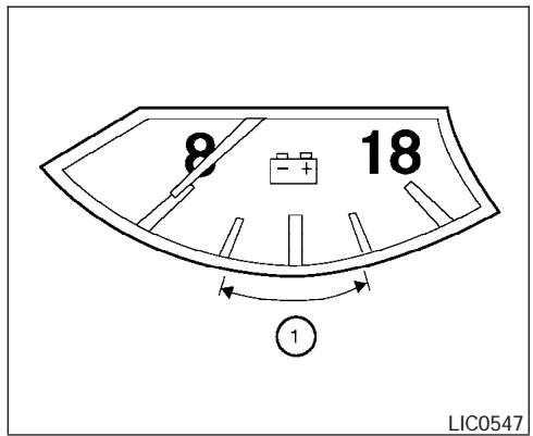
VOLTMETER
When the ignition key is turned to the ON position, the voltmeter indicates the battery voltage. When the engine is running, it indicates the generator voltage.
While cranking the engine, the volts drop below the normal range. If the needle is not in the normal range (11 - 15 volts) ① while the engine is running, it may indicate that the charging system is not functioning properly. Have the system checked by a NISSAN dealer.
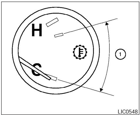
AUTOMATIC TRANSMISSION FLUID TEMPERATURE GAUGE (if so equipped)
This gauge indicates the temperature of the automatic transmission fluid. The automatic transmission fluid temperature is in the normal range ① when the gauge needle points within the zone shown in the illustration.
COMPASS AND OUTSIDE TEMPERATURE DISPLAY

CAUTION
- This gauge is not designed to indicate low automatic transmission fluid level. Use the dipstick to check the fluid level. (See “5-speed automatic transmission fluid” in the “Maintenance and do-it-yourself” section.)
- If the gauge indicates automatic transmission fluid temperature over the normal range, stop the vehicle as soon as safely possible. Have the vehicle checked by a NISSAN dealer. Continued operation of the vehicle may seriously damage the transmission.
This unit has the following functions:
● Measures terrestrial magnetism and indicates heading direction of vehicle
- Indicates outside air temperature
- Indicates possible frozen road conditions
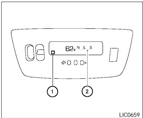
Type A
OUTSIDE TEMPERATURE DISPLAY
Push the mode button ① when the ignition key is in the ON position to change the display as follows: °F → °C → OFF → °F.
- If the outside temperature drops below 37irc F ( 3irc C), the display indicates ICE. The display will continue to indicate ICE until the temperature reaches 41irc F ( 5irc C).
- When the outside temperature is between 130°F (55°C) and 158°F (70°C), the display shows 130°F (55°C).
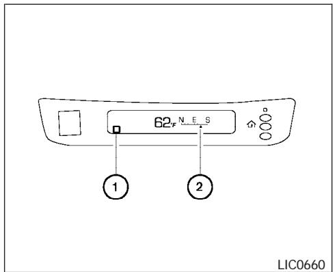
Type B
- When the outside temperature is between -22ircF (-30°C) and -40ircF (-40°C), the display shows -22ircF (-30°C).
- When the outside temperature is lower than -40ircF (-40°C) or higher than 158ircF (70°C), the display shows only — — — though it is operating. This is not a malfunction.
- The outside temperature sensor is located in front of the radiator. The sensor may be affected by road or engine heat, wind direction and other driving conditions. The display may differ from the actual outside tempera-
ture or the temperature displayed on various signs or billboards.
- Temperature display will not increase unless the vehicle is moving faster than 12 mph (20 km/h).
- If the ignition has been off for less than 2 hours and the outside temperature is greater than the last detected temperature, the display will show the last detected temperature when the ignition is turned on.
COMPASS DISPLAY
Push the mode button ① when the ignition key is in the ON position to turn on the compass display. The arrow ② indicates direction.
N: north
E: east
S: south
W: west
If the compass display flashes, calibrate the compass by driving the vehicle one and a half circles at a maximum speed of 6 MPH (10 km/h).
You can also calibrate the compass by driving your vehicle on your everyday route. The compass will be calibrated once it has tracked one and a half circles.
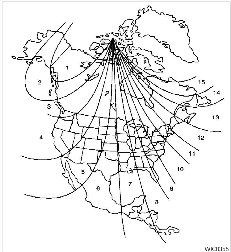
Zone variation change procedure
The difference between magnetic north and geographical north is known as variance. In some areas, this difference can sometimes be great enough to cause false compass readings. Follow these instructions to set the variance for your particular location if this happens:
- With the display turned on, press and hold the mode button for about 5 seconds. The current zone number will appear in the display.
- Find your current location on the zone map. Refer to the illustration. Record the zone number.
- Press the mode button repeatedly to toggle through the zone numbers until the desired number shows in the display. The display should return to the normal compass mode within a few seconds of no button activity.
- If the vehicle changes zones, repeat steps 1 through 3.
Inaccurate compass direction
The compass display is equipped with automatic correction function. If the correct direction is not shown, follow this procedure.
- With the display turned on, press and hold the mode button for about 10 seconds. The compass display will begin to flash.
- Calibrate the compass by driving the vehicle one and a half circles at a maximum speed of 6 MPH (10 km/h).
- After completing the circles, the display should return to normal.
- If the compass deviates from the correct indication soon after repeated adjustment, have the compass checked at an authorized dealer.
- The compass may not indicate the correct compass point in tunnels or while driving up or down a steep hill. (The compass returns to the correct compass point when the vehicle moves to an area where the geomagnetism is stabilized.)
- If a magnet is located in or near the overhead console in the front of the vehicle or the vehicle is driven where the terrestrial magnetism is disturbed, the compass display may not indicate the correct direction.
CAUTION
Do not install a ski rack, antenna, etc., which are attached to the vehicle by means of a magnet. They affect the operation of the compass.
WARNING/INDICATOR LIGHTS AND AUDIBLE REMINDERS
| ABS | or | Anti-lock brake warning light | Low fuel warning light | or | Front passenger air bag status light | ||
| AT CHECK | Automatic transmission check warning light | Low tire pressure warning light | High beam indicator light (Blue) | ||||
| ATP | Automatic transmission park warning light( 📄x4 model) | Low windshield washer fluid warning light | SERVICE ENGINE SOON | Malfunction indicator lamp (MIL) | |||
| BRAKE | or | Brake warning light | Seat belt warning light and chime | Security indicator light (NVIS) | |||
| Charge warning light | Supplemental air bag warning light | SLIP | Slip indicator light | ||||
| CK SUSP | Check suspension warning light (if so equipped) | Automatic transmission position indicator light | 4LO | Transfer 4LO position indicator light( 📄x4 model) | |||
| Door open warning light | CRUISE | Cruise main switch indicator light | Turn signal/hazard indicator lights | ||||
| Engine oil pressure low/engine coolant temperature high warning light | SET | Cruise set switch indicator light | VDCOFF | Vehicle dynamic control off indicator light | |||
| 4WD | 4WD warning light ( 📄x4 model) | 4WD shift indicator light ( 📄x4 model) | |||||
CHECKING BULBS
With all doors closed, apply the parking brake and turn the ignition key to the ON position without starting the engine. The following lights will come on:

BRAKE


4WD
The following lights come on briefly and then go off:
ABS or (ABS), SLIP, (!), VDC OFF, 4LO, AT CHECK, CK SUSP
If any light fails to come on, it may indicate a burned-out bulb or an open circuit in the electrical system. Have the system repaired promptly.
WARNING LIGHTS
ABS
or

Anti-lock brake warning light
If the light comes on while the engine is running, it may indicate the anti-lock brake system is not functioning properly. Have the system checked by a NISSAN dealer.
If an abnormality occurs in the system, the anti-lock function ceases, but the regular braking system continues to operate.
If the light comes on while you are driving, contact a NISSAN dealer for repair.
AT CHECK
Automatic transmission check warning light
When the ignition switch is turned ON, the light comes on for about 2 seconds. If the light comes on at any other time, it may indicate the automatic transmission system is not functioning properly. Have the system checked by a NISSAN dealer.
ATP
Automatic transmission park warning light (4x4 model)
WARNING
- If the ATP light is ON, this indicates that the automatic transmission P (Park) position will not function and the transfer case is in neutral.
- When parking, always make sure that the 4WD shift indicator light illuminates and the parking brake is set. Failure to engage the transfer position in 2WD, AUTO, 4H or 4LO could result in the vehicle moving unexpectedly, resulting in serious personal injury or property damage.
- All mode 4WD: The warning light may come on when the ignition switch is ON and the automatic transmission lever is shifted to the P position while shifting the transfer case between 4H and 4LO. Shift the 4WD shift switch to the 2WD, AUTO, 4H, or 4LO position again to turn off the ATP warning light when the warning light comes on. (Before shifting the 4WD switch into the 4LO position or out of 4LO in the 4H position, move the automatic transmission selector lever into the N position.) Shift
the selector lever into the P position and make sure that the 4WD shift indicator light is ON and the ATP warning light is OFF.)
This light indicates that the automatic transmission parking function is not engaged. If the transfer control is not secured in any drive position while the automatic transmission selector lever is in the P (Park) position, the transmission will disengage and the drive wheels will not lock.
BRAKE
or (!)
Brake warning light
This light functions for both the parking brake and the foot brake systems.
When the ignition key is in the ON position, the light comes on when the parking brake is applied, and also warns of a low brake fluid level. If the light comes on while the engine is running with the parking brake not applied, stop the vehicle and perform the following:
- Check the brake fluid level. Add brake fluid as necessary. See "Brake fluid" in the "Maintenance and do-it-yourself" section of this manual.
- If the brake fluid level is correct, have the brake system checked by a NISSAN dealer.
WARNING
- Your brake system may not be working properly if the warning light is on. Driving could be dangerous. If you judge it to be safe, drive carefully to the nearest service station for repairs. Otherwise, have your vehicle towed because driving it could be dangerous.
- Pressing the brake pedal with the engine stopped and/or a low brake fluid level may increase your stopping distance and braking will require greater pedal effort as well as pedal travel.
- If the brake fluid level is below the MINIMUM or MIN mark on the brake fluid reservoir, do not drive until the brake system has been checked at a NISSAN dealer.

Charge warning light
If this light comes on while the engine is running, it may indicate the charging system is not functioning properly. Turn the engine off and check the generator belt. If the belt is loose, broken, missing, or if the light remains on, see a NISSAN dealer immediately.
CAUTION
Do not continue driving if the generator belt is loose, broken or missing.
CK SUSP
Check suspension warning light (if so equipped)
This light may indicate a malfunction in the auto-leveling suspension.
For additional information, refer to “Jacking up vehicle and removing the damaged tire” in the “In case of emergency” section of this manual.

Door open warning light
This light comes on when any of the doors are not closed securely while the ignition key is in the ON position.

Engine oil pressure low/Engine coolant temperature high warning light
This light warns of low engine oil pressure or high engine coolant temperature.
If the light flickers or comes on during normal driving, pull off the road in a safe area, stop the engine and allow it to cool. If the light remains on after checking the oil and coolant, stop the en-
gine immediately and call a NISSAN dealer or other authorized repair shop.
This light is not designed to indicate a low oil or low coolant level. Check the oil level with the dipstick and check the coolant level on the reservoir. See “Engine oil” and “Checking engine coolant level” in the “Maintenance and do-it-yourself” section of this manual. Also see “If your vehicle overheats” in the “In case of emergency” section of this manual.
CAUTION
- Running the engine with the engine oil pressure warning light on could cause serious damage to the engine almost immediately. Such damage is not covered by warranty. Turn off the engine as soon as it is safe to do so.
- If the gauge indicates engine coolant temperature over the normal range, stop the vehicle as soon as safely possible. If the engine is overheated, continued operation of the vehicle may seriously damage the engine. See “If your vehicle overheats” in the “In case of emergency” section for immediate action required.
4WD
4WD warning light (4x4 model)
The 4WD warning light comes on when the key switch is turned to ON. It turns off soon after the engine is started.
If the engine or vehicle is not functioning properly, the warning light will either remain illuminated or blink. See “4WD warning light” in the “Starting and driving” section.

CAUTION
- If the warning light comes on or blinks during operation, have your vehicle checked by a NISSAN dealer as soon as possible.
- Do not drive on dry hard surface roads in the 4H or 4LO position. If the 4WD warning light turns on when you are driving on dry hard surface roads:
- in the AUTO or 4H position, shift the 4WD shift switch to 2WD.
- in the 4LO position, stop the vehicle, move the automatic transmission shift selector lever to the N position and shift the 4WD shift switch to 2WD.
- If the warning light is still on after the above operation, have your vehicle checked by a NISSAN dealer as soon as possible.

Low fuel warning light
This light comes on when the fuel level in the fuel tank is getting low. Refuel as soon as it is convenient, preferably before the fuel gauge reaches E (Empty). There will be a small reserve of fuel in the tank when the fuel gauge needle reaches E (Empty).

Low tire pressure warning light
After the ignition switch is turned ON, this light comes on for about 1 second and turns off.
This light warns of low tire pressure.
NISSAN's low tire pressure warning system is a tire pressure monitoring system. It monitors tire pressure of all tires except the spare. When the tire pressure monitoring system warning light is lit, one or more of your tires is significantly underinflated. You should stop and check your tires as soon as possible, and inflate them to the proper pressure as indicated on the vehicle's tire information placard. Driving on a significantly underinflated tire causes the tire to overheat and can
lead to tire failure. Under-inflation also reduces fuel efficiency and tire tread life, and may affect the vehicle's handling and stopping ability. Each tire, including the spare, should be checked monthly when cold and set to the recommended inflation pressure as specified in the vehicle placard and owner's manual.
The recommended inflation pressure may also be found on the Tire and Loading Information Label.
Low tire pressure warning:
If the vehicle is being driven with very low tire pressure (lower than 28 psi, 193 kPa), the light will illuminate and the chime will sound for about 10 seconds. If you select the tire pressure information in the display (if so equipped), the FLAT TIRE warning message will be displayed.
For additional information, see “Low tire pressure warning system” in the “Starting and driving” section and “Low tire pressure warning system” in the “In case of emergency” section.

WARNING
- If the light does not come on with the key switch turned ON, have the vehicle checked by a NISSAN dealer as soon as possible.
- If the light comes on while driving, avoid sudden steering maneuvers or abrupt braking, reduce vehicle speed, pull off the road to a safe location and stop the vehicle as soon as possible. Serious vehicle damage could occur and may lead to an accident and could result in serious personal injury. Check the tire pressure for all four tires. Adjust the tire pressure to the recommended COLD tire pressure shown on the Tire and Loading Information label to turn the low tire pressure warning light OFF. If the light still comes on while driving after adjusting the tire pressure, a tire may be flat. If you have a flat tire, replace it with a spare tire as soon as possible.
- When a spare tire is mounted or a wheel is replaced, tire pressure will not be indicated and the low tire pressure warning system will not function. Contact your NISSAN dealer as soon as possible for tire replacement and/or system resetting.
CAUTION
- The low tire pressure warning system is not a substitute for the regular tire pressure check. Be sure to check the tire pressure regularly.
- If the vehicle is being driven at speeds of less than 20 MPH (32 km/h), the low tire pressure warning system may not operate correctly.
- Be sure to install the specified size of tires to the 4 wheels correctly.

Low windshield washer fluid warning light
This light comes on when the windshield washer fluid is at a low level. Add windshield washer fluid as necessary. See “Window washer fluid” in the “Maintenance and do-it-yourself” section of this manual.

Seat belt warning light and chime
The light and chime remind you to fasten your seat belts. The light illuminates whenever the ignition key is turned to the ON or START position and remains illuminated until the driver's seat belt
is fastened. At the same time, the chime sounds for about 6 seconds unless the driver's seat belt is securely fastened.
Refer to “Seat belts” in the “Safety—Seats, seat belts and supplemental restraint system” section for precautions on seat belt usage.

Supplemental air bag warning light
When the ignition key is in the ON or START position, the supplemental air bag warning light illuminates for about 7 seconds and then turns off. This means the system is operational.
If any of the following conditions occur, the supplemental front air bags, supplemental side air bags (if so equipped), curtain side-impact and rollover air bags, and pre-tensioner seat belt systems need servicing and your vehicle must be taken to a NISSAN dealer:
- The supplemental air bag warning light remains on after approximately 7 seconds.
- The supplemental air bag warning light flashes intermittently.
- The supplemental air bag warning light does not come on at all.
Unless checked and repaired, the supplemental restraint system (air bag system) and/or the pretensioner seat belts may not function properly. For additional details see “Supplemental restraint system” in the “Safety—Seats, seat belts and supplemental restraint system” section of this manual.
WARNING
If the supplemental air bag warning light is on, it could mean that the supplemental front air bag, supplemental side air bag, curtain side-impact and rollover air bag systems (if so equipped) and/or pretensioner seat belt systems will not operate in an accident. To help avoid injury to yourself or others, have your vehicle checked by a NISSAN dealer as soon as possible.
INDICATOR LIGHTS

Automatic transmission position indicator light
When the ignition key is turned to the ON position, this indicator light shows the automatic transmission selector lever position. See “Driving the vehicle” in the “Starting and driving” section of this manual.
CRUISE Cruise main switch indicator light
The light comes on when the cruise control main switch is pushed. The light goes out when the main switch is pushed again. When the cruise main switch indicator light comes on, the cruise control system is operational.
SET Cruise set switch indicator light
The light comes on while the vehicle speed is controlled by the cruise control system. If the light blinks while the engine is running, it may indicate the cruise control system is not functioning properly. Have the system checked by a NISSAN dealer.
4WD shift indicator light (4x4 model)
The light should turn off within 1 second after turning the ignition switch to ON.
While the engine is running, the 4WD shift indicator light will illuminate the position selected by the 4WD shift switch.
The 4WD shift indicator light may blink while shifting from one drive mode to the other.
OFF or 2
Front passenger air bag status light
The front passenger air bag status light (OFF or 2 ) will be lit and the passenger front air bag will be OFF depending on how the front passenger seat is being used.
For front passenger air bag status light operation, see “Front passenger air bag and status light” in the “Safety — Seats, seat belts and supplemental restraint system” section of this manual.
High beam indicator light (Blue)
This blue light comes on when the headlight high beams are on and goes out when the low beams are selected.
The high beam indicator light also comes on when the passing signal is activated.
SERVICE ENGINE SOON Malfunction indicator lamp (MIL)
If this indicator lamp comes on steady or blinks while the engine is running, it may indicate a potential emission control malfunction.
The malfunction indicator lamp may also come on steady if the fuel filler cap is loose or missing, or if the vehicle runs out of fuel. Check to make sure the fuel filler cap is installed and closed tightly,
and that the vehicle has at least 3 gallons (11.4 liters) of fuel in the fuel tank.
After a few driving trips, the SERVICE ENGINE 500N lamp should turn off if no other potential emission control system malfunction exists.
If this indicator lamp comes on steady for 20 seconds and then blinks for 10 seconds when the engine is not running, it indicates that the vehicle is not ready for an emission control system inspection/maintenance test. See “Readiness for inspection/maintenance (I/M) test” in the “Technical and consumer information” section of this manual.
Operation
The malfunction indicator lamp will come on in one of two ways:
- Malfunction indicator lamp on steady — An emission control system malfunction has been detected. Check the fuel filler cap. If the fuel filler cap is loose or missing, tighten or install the cap and continue to drive the vehicle. The SERVICE ENGINE SOON lamp should turn off after a few driving trips. If the SERVICE ENGINE SOON lamp does not turn off after a few driving trips, have the vehicle inspected by a NISSAN dealer. You do not need to have your vehicle towed to the dealer.
- Malfunction indicator lamp blinking — An engine misfire has been detected which may damage the emission control system. To reduce or avoid emission control system damage:
- do not drive at speeds above 45 MPH (72 km/h).
- avoid hard acceleration or deceleration.
– avoid steep uphill grades. - if possible, reduce the amount of cargo being hauled or towed.
The malfunction indicator lamp may stop blinking and come on steady. Have the vehicle inspected by a NISSAN dealer. You do not need to have your vehicle towed to the dealer.
CAUTION
Continued vehicle operation without having the emission control system checked and repaired as necessary could lead to poor driveability, reduced fuel economy, and possible damage to the emission control system.

Security indicator light (NVIS)
This light blinks whenever the ignition switch is in the LOCK, OFF or ACC position. This function indicates the security system equipped on the vehicle is operational.
For additional information, see "Security systems" later in this section.
SLIP
Slip indicator light
This indicator light will blink when the traction control system is limiting wheel spin. Slippery road conditions may exist if the slip indicator blinks on. If this happens, adjust your driving accordingly.
The slip indicator light also comes on when you turn the ignition key to the ON position. The light will turn off after about 2 seconds if the system is operational. If the light does not come on or does not go off, have the traction control system checked by a NISSAN dealer.
4LO
Transfer 4LO position
indicator light (4x4 model)
The light should turn off within 1 second after turning the ignition switch to ON.
This light comes on when the 4WD shift switch is set in the 4LO position with the ignition key in the ON position.
If the 4WD shift switch is set in the 4LO position and the light blinks, stop the vehicle, drive slowly forward and the light will turn on.
When you shift between 4H and 4LO, stop the vehicle, move the automatic transmission selector lever to the N (Neutral) position, then push the 4WD shift switch and move it to 4LO or 4H.
The transfer case may be damaged if you shift the switch while driving.
You cannot move the transfer 4WD shift switch between 4H and 4LO unless you have first stopped the vehicle and moved the automatic transmission shift selector lever to N (Neutral). Make sure the transfer 4LO position indicator light turns on when you shift the 4WD shift switch to 4LO.
The indicator light may blink while shifting from one drive mode to the other.

Turn signal/hazard indicator lights
The appropriate light flashes when the turn signal switch is activated.
Both lights flash when the hazard switch is turned on.

Vehicle dynamic control off indicator light
This indicator light comes on when the vehicle dynamic control off switch is pushed to OFF. This indicates the vehicle dynamic control system is not operating.
Push the vehicle dynamic control off switch again or restart the engine and the system will operate normally. See “Vehicle dynamic control (VDC) system” in the “Starting and driving” section of this manual.
The vehicle dynamic control light also comes on when you turn the ignition key to the ON position. The light will turn off after about 2 seconds if the system is operational. If the light stays on or comes on along with the SLIP indicator light while you are driving, have the vehicle dynamic control system checked by a NISSAN dealer.
While the vehicle dynamic control system is operating, you might feel slight vibration or hear the system working when starting the vehicle or accelerating, but this is normal.
AUDIBLE REMINDERS Brake pad wear warning
The front disc brake pads have audible wear warnings. When a front brake pad requires replacement, it makes a high pitched scraping sound when the vehicle is in motion, whether or not the brake pedal is depressed. Have the brakes checked as soon as possible if the warning sound is heard.
Key reminder chime
A chime sounds if the driver's door is opened while the key is left in the ignition switch. Remove the key and take it with you when leaving the vehicle.
Light reminder chime
With the ignition switch in the OFF position, a chime sounds when the driver's door is opened if the headlights or parking lights are on.
Turn the headlight control switch off before leaving the vehicle.
natural_image
Diagram of a car with concentric circular patterns and a figure inside, no text or symbols presentYour vehicle has two types of security systems:
- Vehicle security system
- NISSAN Vehicle Immobilizer System—NVIS
VEHICLE SECURITY SYSTEM
The vehicle security system provides visual and audible alarm signals if someone opens the doors when the system is armed. It is not, however, a motion detection type system that activates when a vehicle is moved or when a vibration occurs.
The system helps deter vehicle theft but cannot prevent it, nor can it prevent the theft of interior or exterior vehicle components in all situations. Always secure your vehicle even if parking for a brief period. Never leave your keys in the ignition, and always lock the vehicle when unattended. Be aware of your surroundings, and park in secure, well-lit areas whenever possible.
Many devices offering additional protection, such as component locks, identification markers, and tracking systems, are available at auto supply stores and specialty shops. Your NISSAN dealer may also offer such equipment. Check with your insurance company to see if you may be eligible for discounts for various theft protection features.
How to arm the vehicle security system
- Close all windows. (The system can be armed even if the windows are open.)
- Remove the key from the ignition switch.
- Close all doors. Lock all doors. The doors can be locked with the key, power door lock switch or with the keyfob.
Keyfob operation:
- Push the 🔒 button on the keyfob. All doors lock. The hazard lights flash twice and the horn beeps once to indicate all doors are locked.
- When the 🔒 button is pushed with all doors locked, the hazard lights flash twice and the horn beeps once as a reminder that the doors are already locked.
The horn may or may not beep. Refer to "Silencing the horn beep feature" (vehicles without navigation system) in the "Pre-driving checks and adjustments" section or "Vehicle electronic systems" (vehicles with navigation system) in the "Display screen, heater, air conditioner and audio systems" section.
- Confirm that the indicator light comes on. The light stays on for about 30 seconds. The vehicle security system is now pre-armed. After about 30 seconds the vehicle security system automatically shifts into the armed phase. The light begins to flash once every 3 seconds. If, during the 30-second pre-arm time period, the door is unlocked by the key or the keyfob, or the ignition key is turned to ACC or ON, the system will not arm.
- If the key is turned slowly when locking the door, the system may not arm. Furthermore, if the key is turned beyond the vertical position toward the unlock position to remove the key, the system may be disarmed when the key is removed. If the indicator light fails to glow for 30 seconds, unlock the door once and lock it again.
- Even when the driver and/or passengers are in the vehicle, the system will arm with all doors closed and locked with the ignition key in the OFF position.
Vehicle security system activation
The vehicle security system will give the following alarm:
- The headlights blink and the horn sounds intermittently.
- The alarm automatically turns off after approximately 50 seconds. However, the alarm reactivates if the vehicle is tampered with again. The alarm can be shut off by unlocking a door with the key, or by pressing the button on the keyfob.
The alarm is activated by:
- opening a door without using the key or keyfob (even if the door is unlocked by using the inside lock knob or the power door lock switch).
How to stop an activated alarm
The alarm stops only by unlocking a door with the key, or by pressing the 🔒 button on the key-fob.
NISSAN VEHICLE IMMOBILIZER SYSTEM (NVIS)
The NISSAN Vehicle Immobilizer System (NVIS) will not allow the engine to start without the use of a registered NVIS key.
If the engine fails to start using a registered NVIS key (for example, when interference is caused by another NVIS key, an automated toll road device or automatic payment device on the key ring), restart the engine using the following procedures:
- Leave the ignition switch in the ON position for approximately 5 seconds.
- Turn the ignition switch to the OFF or LOCK position, and wait approximately 10 seconds.
- Repeat steps 1 and 2.
- Restart the engine while holding the device (which may have caused the interference) separate from the registered NVIS key.
If the no start condition re-occurs, NISSAN recommends placing the registered NVIS key on a separate key ring to avoid interference from other devices.
Statement related to Section 15 of FCC Rules for NISSAN Vehicle Immobilizer System (CONT ASSY — IMMOBILIZER, ANT ASSY — IMMOBILIZER)
This device complies with part 15 of the FCC Rules and RSS-210 of Industry Canada. Operation is subject to the following two conditions;
(1) This device may not cause harmful interference, and (2) this device must accept any interference received, including interference that may cause undesired operation of the device.
CHANGES OR MODIFICATIONS NOT EXPRESSLY APPROVED BY THE MANUFACTURER FOR COMPLIANCE COULD VOID THE USER'S AUTHORITY TO OPERATE THE EQUIPMENT.
WINDSHIELD WIPER AND WASHER SWITCH
natural_image
Silhouette of a car with a key inside, no text or symbols presentSecurity indicator light
The security indicator light blinks whenever the ignition switch is in the LOCK, OFF or ACC position. This function indicates the NISSAN Vehicle Immobilizer System (NVIS) is operational.
If the NVIS is malfunctioning, the light will remain on while the ignition key is in the ON position.
If the light still remains on and/or the engine will not start, see a NISSAN dealer for NVIS service as soon as possible. Please bring all NVIS keys that you have when visiting your NISSAN dealer for service.
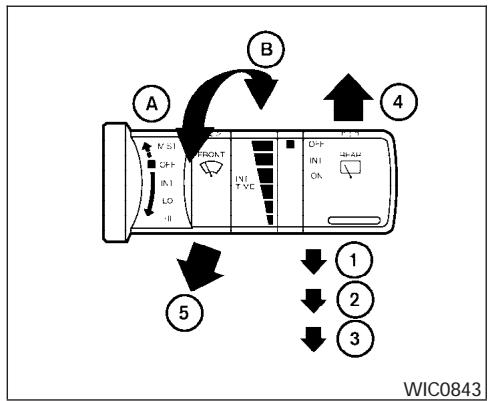
flowchart
graph TD
    A["Directional Control Panel"] --> B["Control Signals"]
    B --> C["Action Buttons 1-4"]
    C --> D["Downward Arrow ①"]
    C --> E["Downward Arrow ②"]
    C --> F["Downward Arrow ③"]
    C --> G["Downward Arrow ④"]
    style A fill:#f9f,stroke:#333
    style B fill:#ccf,stroke:#333
    style C fill:#cfc,stroke:#333
    style D fill:#fcc,stroke:#333
    style E fill:#cff,stroke:#333
    style F fill:#ffc,stroke:#333
SWITCH OPERATION
The windshield wiper and washer operates when the ignition switch is in the ON position.
Push the lever down to operate the wiper at the following speed:
① Intermittent — intermittent operation can be adjusted by turning the knob toward Ⓐ (Slower) or Ⓑ (Faster). Also, the intermittent operation speed varies in accordance with the vehicle speed. (For example, when the vehicle speed is high, the intermittent operation speed will be faster.)
NOTE:
You can turn on or turn off the driving speed dependent intermittent wiper function for vehicles with navigation system. Refer to "Vehicle electronic systems" in the "Display screen, heater, air conditioner and audio systems" section later in this manual.
② Low — continuous low speed operation
③ High — continuous high speed operation
Push the lever up ④ to have one sweep operation of the wiper.
Pull the lever toward you ⑤ to operate the washer. The wiper will also operate several times.

WARNING
In freezing temperatures the washer solution may freeze on the windshield and obscure your vision which may lead to an accident. Warm the windshield with the defroster before you wash the windshield.

CAUTION
- Do not operate the washer continuously for more than 30 seconds.
- Do not operate the washer if the reservoir tank is empty.
REAR WINDOW WIPER AND WASHER SWITCH
- Do not fill the window washer reservoir tank with washer fluid concentrates at full strength. Some methyl alcohol based washer fluid concentrates may permanently stain the grille if spilled while filling the window washer reservoir tank.
- Pre-mix washer fluid concentrates with water to the manufacturer's recommended levels before pouring the fluid into the window washer reservoir tank. Do not use the window washer reservoir tank to mix the washer fluid concentrate and water.
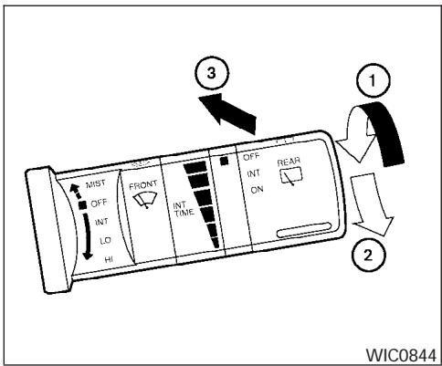
The rear window wiper and washer operate when the ignition switch is in the ON position.
Turn the switch clockwise from the OFF position to operate the wiper.
① Intermittent – intermittent operation (not adjustable)
② On – continuous low speed operation
Push the switch forward ③ to operate the washer. The wiper will also operate several times.

WARNING
In freezing temperatures the washer solution may freeze on the window and obscure your vision. Warm the rear window with the defroster before you wash the rear window.

CAUTION
- Do not operate the washer continuously for more than 30 seconds.
- Do not operate the washer if the reservoir tank is empty.
- Do not fill the window washer reservoir tank with washer fluid concentrates at full strength. Some methyl alcohol based washer fluid concentrates may permanently stain the grille if spilled while filling the window washer reservoir tank.
- Pre-mix washer fluid concentrates with water to the manufacturer's recommended levels before pouring the fluid into the window washer reservoir tank. Do not use the window washer reservoir tank to mix the washer fluid concentrate and water.
REAR WINDOW AND OUTSIDE MIRROR DEFROSTER SWITCH
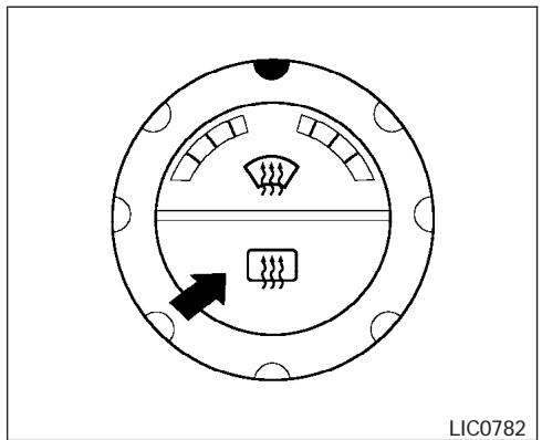
natural_image
Circular diagram with internal components and directional arrow, no readable text or symbolsType A
To defrost the rear window glass and outside mirrors, start the engine and push the rear window defroster switch on. The rear window defroster indicator light on the switch comes on. Push the switch again to turn the defroster off.
The rear window defroster automatically turns off after approximately 15 minutes.

CAUTION
When cleaning the inner side of the rear window, be careful not to scratch or damage the rear window defroster.
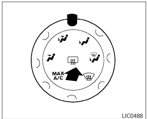
Type B
HEADLIGHT AND TURN SIGNAL SWITCH
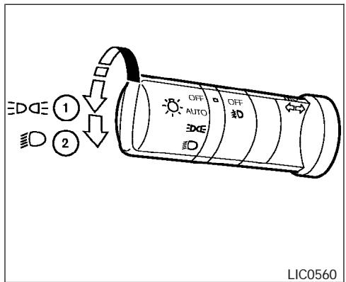
Type A
HEADLIGHT CONTROL SWITCH
Lighting
① When turning the switch to the EDGE position, the front parking, tail, license plate and instrument panel lights come on.
② When turning the switch to the position, the headlights come on and all the other lights remain on.
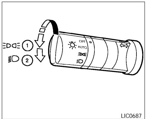
Type B

CAUTION
Use the headlights with the engine running to avoid discharging the vehicle battery.
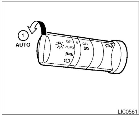
Autolight system
The autolight system allows the headlights to be set so they turn on and off automatically. The autolight system can:
- Turn on the headlights, front parking, tail, license plate and instrument panel lights automatically when it is dark.
- Turn off all the lights when it is light.
- Keep all the lights on for 45 seconds after you turn the key to OFF and all doors are closed.
NOTE:
Autolight activation sensitivity and the time delay for autolight shutoff is adjustable for vehicles with navigation system. See “Vehicle electronic systems” in the “Display screen, heater, air conditioner and audio systems” section later in this manual.
To turn on the autolight system:
- Turn the headlight switch to the AUTO position ①.
- Turn the ignition key to ON.
- The autolight system automatically turns the headlights on and off.
Initially, if the ignition switch is turned OFF and a door is opened and left open, the headlights remain ON for 5 minutes. If another door is opened during the 5 minutes, then the 5 minute timer is reset.
To turn the autolight system off, turn the switch to the OFF, EDDE, or ID position.
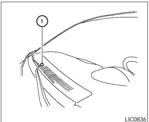
Be sure you do not put anything on top of the autolight sensor ① located in the top side of the instrument panel. The autolight sensor controls the autolight; if it is covered, the autolight sensor reacts as if it is dark out and the headlights will illuminate. If this occurs while parked with the engine off and the key in the ON position, your vehicle's battery could become discharged.
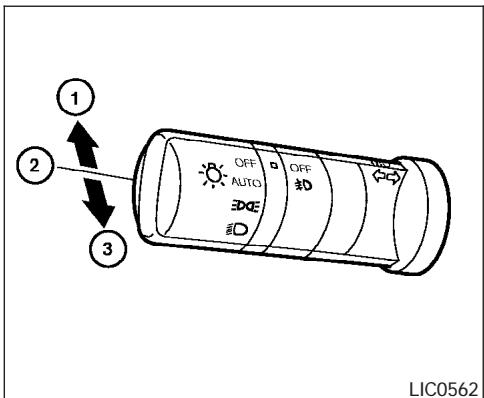
Headlight beam select
① To select the high beam function, push the lever forward. The high beam lights come on and the light illuminates.
② Pull the lever back to select the low beam.
③ Pulling and releasing the lever flashes the headlight high beams on and off.
Battery saver system
If the ignition switch is turned OFF while the headlight switch is in the EDDE or ID position, the headlights will turn off after 5 minutes.
After the headlights automatically turn off with the headlight switch in the ☐ or ☐ position, the headlights will illuminate again for 5 minutes if the headlight switch is moved to the OFF position and then turned to the ☐ or ☐ position.

CAUTION
Even though the battery saver feature automatically turns off the headlights after a period of time, you should turn the headlight switch to the OFF position when the engine is not running to avoid discharging the vehicle battery.
DAYTIME RUNNING LIGHT SYSTEM (Canada only)
The headlights automatically illuminate at a reduced intensity when the engine is started with the parking brake released. The daytime running lights operate with the headlight switch in the OFF position or in the EDDS position. Turn the headlight switch to the ☐ position for full illumination when driving at night.
If the parking brake is applied before the engine is started, the daytime running lights do not illuminate. The daytime running lights illuminate when the parking brake is released. The daytime running lights will remain on until the ignition switch is turned off.

WARNING
When the daytime running light system is active, tail lights on your vehicle are not on. It is necessary at dusk to turn on your headlights. Failure to do so could cause an accident injuring yourself and others.
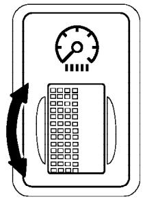
natural_image
Simple line drawing of a control panel with a speedometer and grid layout (no text or symbols)LIC0392
INSTRUMENT BRIGHTNESS CONTROL
The instrument brightness control operates when the headlight control switch is in the D∞ , D or AUTO position (with autolights activated).
Turn the control to adjust the brightness of instrument panel lights when driving at night.
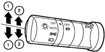
LIC0563
TURN SIGNAL SWITCH
Turn signal
① Move the lever up or down to signal the turning direction. When the turn is completed, the turn signals cancel automatically.
Lane change signal
② To signal a lane change, move the lever up or down to the point where the indicator light begins to flash, but the lever does not latch.
HAZARD WARNING FLASHER SWITCH

FOG LIGHT SWITCH (if so equipped)
To turn the fog lights on, turn the headlight switch to the position, then turn the fog light switch to the position. To turn them off, turn the fog light switch to the OFF position.
The headlights must be on and the low beams selected for the fog lights to operate. The fog lights automatically turn off when the high beam headlights are selected.
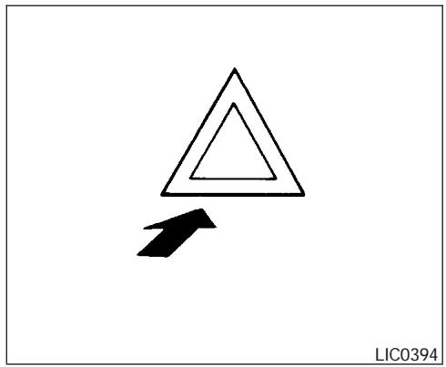
natural_image
Abstract geometric diagram with nested triangles and an arrow, no text or symbols presentPush the switch on to warn other drivers when you must stop or park under emergency conditions. All turn signal lights flash.

WARNING
- If stopping for an emergency, be sure to move the vehicle well off the road.
- Do not use the hazard warning flashers while moving on the highway unless unusual circumstances force you to drive so slowly that your vehicle might become a hazard to other traffic.
- Turn signals do not work when the hazard warning flasher lights are on.
The flashers will operate with the ignition switch in any position.
Some state laws may prohibit the use of the hazard warning flasher switch while driving.
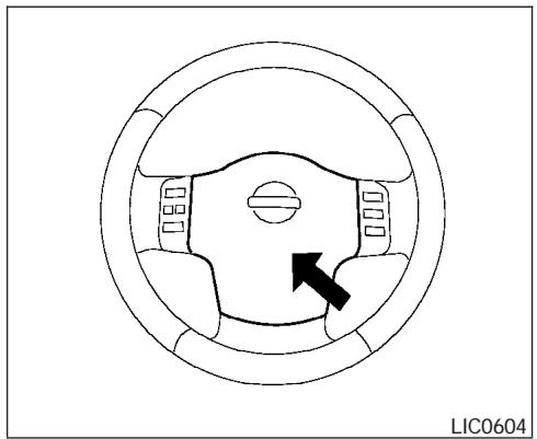
natural_image
Top-down diagram of a circular mechanical or electrical component with a black arrow indicating direction (no text or symbols)To sound the horn, push the center pad area of the steering wheel.
WARNING
Do not disassemble the horn. Doing so could affect proper operation of the supplemental front air bag system. Tampering with the supplemental front air bag system may result in serious personal injury.
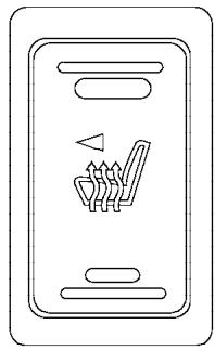
natural_image
Simple line drawing of a vehicle seatbelt with a triangular symbol on the side panel (no text or labels)LIC0690
The front seats are warmed by built-in heaters (if so equipped).
- Start the engine.
- Push the - (low) or - (high) position of the switch, as desired, depending on the temperature. The indicator light in the switch will illuminate.
The heater is controlled by a thermostat, automatically turning the heater on and off. The indicator light will remain on as long as the switch is on.
- When the seat is warmed or before you leave the vehicle, be sure to turn the switch off.
CAUTION
- Do not use the seat heater for extended periods or when no one is using the seat.
- Do not put anything on the seat which insulates heat, such as a blanket, cushion, seat cover, etc. Otherwise, the seat may become overheated.
- Do not place anything hard or heavy on the seat or pierce it with a pin or similar object. This may result in damage to the heater.
- Any liquid spilled on the heated seat should be removed immediately with a dry cloth.
- When cleaning the seat, never use gasoline, benzine, thinner, or any similar materials.
- If any abnormalities are found or the heated seat does not operate, turn the switch off and have the system checked by your NISSAN dealer.
- The battery could run down if the seat heater is operated while the engine is not running.
VEHICLE DYNAMIC CONTROL (VDC) OFF SWITCH
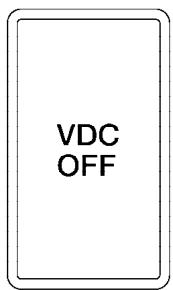
WIC0534
The vehicle should be driven with the Vehicle Dynamic Control (VDC) system on for most driving conditions.
If the vehicle is stuck in mud or snow, the VDC system reduces the engine output to reduce wheel spin. The engine speed will be reduced even if the accelerator is depressed to the floor. If maximum engine power is needed to free a stuck vehicle, turn the VDC system off.
To turn off the VDC system, push the VDC OFF switch. The VDC OFF indicator will come on.
Push the VDC OFF switch again or restart the engine to turn ON the system. See “Vehicle dynamic control (VDC) system” in the “Starting and driving” section.
REAR SONAR SYSTEM OFF SWITCH (if so equipped)

LIC0471
WARNING
The rear sonar system is a convenience but it is not a substitute for proper backing. Always turn and check that it is safe to do so before backing up. Always back up slowly.
The rear sonar system is active when the ignition is in the ON position and the shift selector lever is in R (Reverse).
When sensors detect obstacles within 6 ft (1.8 m) of the rear bumper, a beeping tone is emitted.
The rear sonar system can be disabled by pushing the OFF switch. When the system is disabled,
the indicator light on the switch will illuminate. Push the switch again to enable the system. The indicator light will go off.
The system will automatically reset the next time the ignition switch is turned on.
See “Rear sonar system” in the “Starting and driving” section.
TOW MODE SWITCH
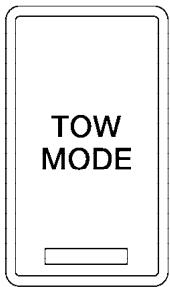
LIC0594
Tow mode should be used when pulling a heavy trailer or hauling a heavy load. Using tow mode at other times may cause unnecessary transmission shifting and reduced fuel economy.
Press the tow mode switch to activate tow mode. The indicator light on the tow mode switch illuminates when tow mode is selected. Press the tow mode switch again to turn tow mode OFF.
Tow mode is automatically canceled when the key is turned OFF.
For additional information, refer to “Tow mode” in the “Technical and consumer information” section later in this manual.
POWER OUTLET
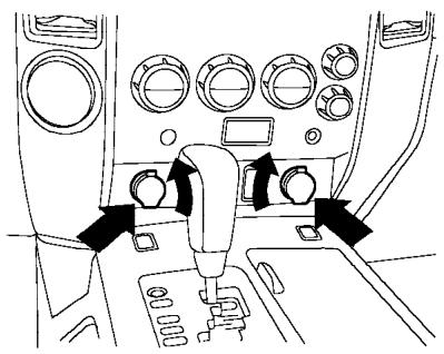
natural_image
Interior view of a vehicle air intake console with directional arrows indicating traffic flow (no text or symbols)LIC0549
Front row
The power outlets are for powering electrical accessories such as cellular telephones.
The power outlets located on the driver's side of the instrument panel and in the luggage area are powered directly by the vehicle's battery.
The power outlets located on the passenger's side of the instrument panel and in the 2nd row are powered only when the ignition key is in the ACC or ON position.
Open the cap to use a power outlet.
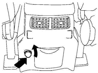
natural_image
Line drawing of a car interior showing airflow direction and seatbelt (no text or symbols)LIC0550
2nd row
CAUTION
- The outlet and plug may be hot during or immediately after use.
- Only certain power outlets are designed for use with a cigarette lighter unit. Do not use any other power outlet for an accessory lighter. See your NISSAN dealer for additional information.
- Do not use with accessories that exceed a 12 volt, 120W (10A) power draw. Do not use double adapters or more than one electrical accessory.
CIGARETTE LIGHTER
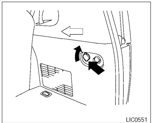
Luggage area
- Use power outlets with the engine running to avoid discharging the vehicle battery.
- Avoid using power outlets when the air conditioner, headlights or rear window defroster is on.
-
Before inserting or disconnecting a plug, be sure the electrical accessory being used is turned OFF.
-
Push the plug in as far as it will go. If good contact is not made, the plug may overheat or the internal temperature fuse may open.
- When not in use, be sure to close the cap. Do not allow water to contact the outlet.
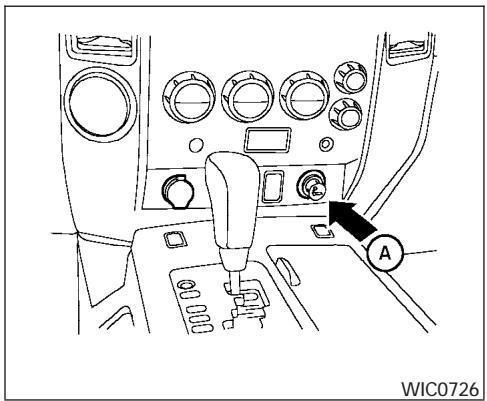
natural_image
Interior view of a car dashboard with steering wheel, gear shift, and control panel (no text or symbols visible)This power outlet Ⓐ can be used with an accessory cigarette lighter element. Contact your NISSAN dealer for information.
This power outlet can also be used for powering electrical accessories such as cellular telephones.
CAUTION
- The cigarette lighter should not be used while driving so full attention may be given to vehicle operation.
- The outlet and plug may be hot during or immediately after use.
STORAGE
- Do not use any other power outlet for an accessory lighter.
- Do not use with accessories that exceed a 12 volt, 120W (10A) power draw. Do not use double adapters or more than one electrical accessory.
- Use power outlets with the engine running to avoid discharging the vehicle battery.
- Avoid using power outlets when the air conditioner, headlights or rear window defroster is on.
- Before inserting or disconnecting a plug, be sure the electrical accessory being used is turned OFF.
- Push the plug in as far as it will go. If good contact is not made, the plug may overheat or the internal temperature fuse may open.
- When not in use, be sure to close the cap. Do not allow water to contact the outlet.
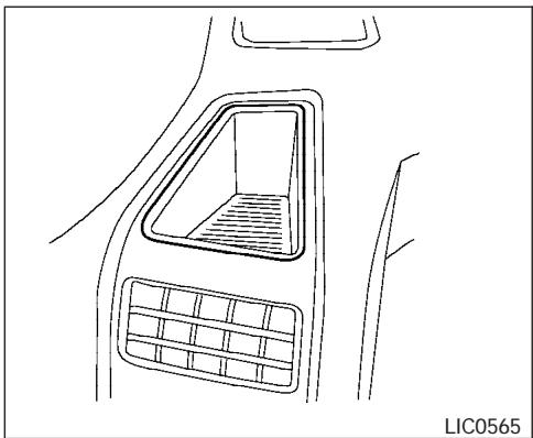
natural_image
Line drawing of a car interior with a vent and grating (no text or symbols)Side tray
INSTRUMENT PANEL STORAGE
TRAYS

WARNING
Do not place sharp objects in the trays to help prevent injury in an accident or sudden stop.
The rubber mats can be removed for cleaning.
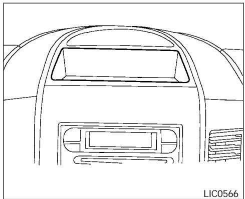
natural_image
Line drawing of a car's rear window and dashboard (no text or symbols)Center tray (if so equipped)
CONSOLE BOX

WARNING
The center console box should not be used while driving so full attention may be given to vehicle operation.
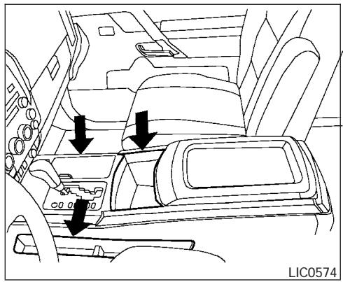
natural_image
Interior view of a car showing the dashboard and seat with directional arrows indicating movement (no text or symbols present)Console box storage trays
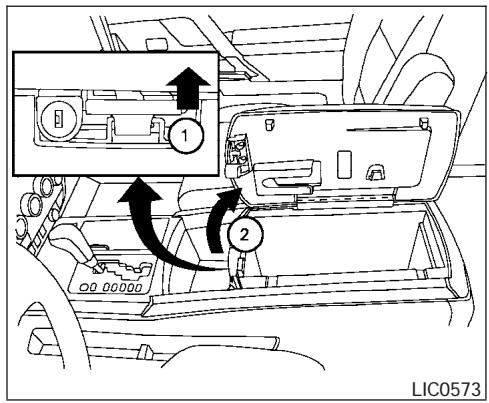
Console box storage
Pull up on the lever ① to open the console box lid ②.
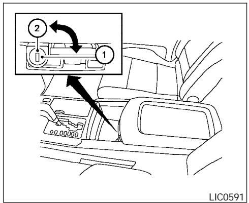
Console box lock
Use the master key to lock ① or unlock ② the console box.
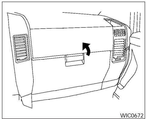
natural_image
Line drawing of a car front bumper with airflow arrow indicating direction (no text or symbols)GLOVE BOX
Open the glove box by pulling the handle.
WARNING
Keep glove box lid closed while driving to help prevent injury in an accident or a sudden stop.
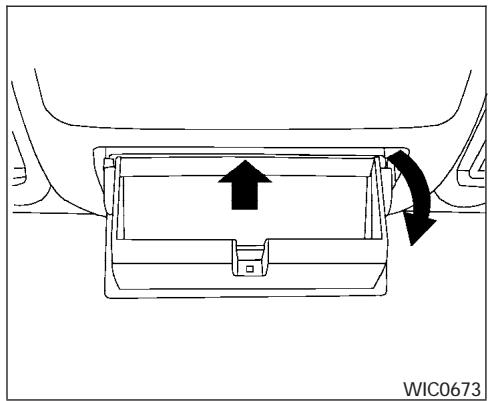
natural_image
Diagram of a car interior showing airflow direction with arrows and label WIC0673 (no text or symbols on diagram itself)SUNGLASSES HOLDER
To open the sunglasses holder, push and release.
WARNING
- The sunglasses holder should not be used while driving so full attention may be given to vehicle operation.
- Keep the sunglasses holder closed while driving to prevent an accident.
CAUTION
- Do not use for anything other than sunglasses.
- Do not leave sunglasses in the sunglasses holder while parking in direct sunlight. The heat may damage the sunglasses.
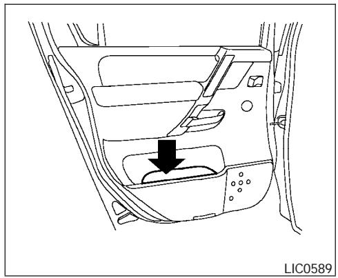
natural_image
Line drawing of a car interior showing the dashboard and seat area with a black arrow indicating a component (no text or symbols present)MAP POCKETS
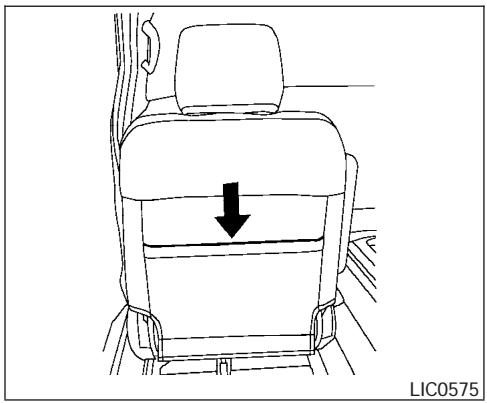
natural_image
Line drawing of a car seat with a downward arrow indicating motion (no text or symbols)SEATBACK POCKET
The seatback pocket is located on the back of the driver seat. The pocket can be used to store maps.
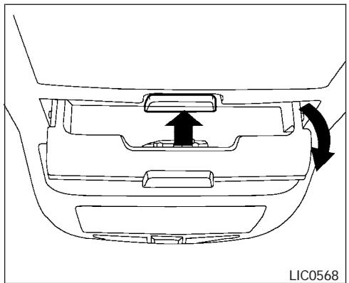
natural_image
Diagram of a car interior showing a handle and seat with directional arrows indicating movement (no text or symbols)Small bin
OVERHEAD CONSOLE
Storage bins

WARNING
Keep storage bins closed while driving to help prevent injury in an accident or a sudden stop.
Push the button to open a storage bin.
Push the lid up to close.
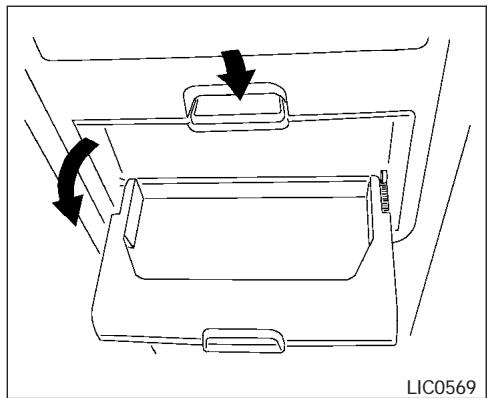
natural_image
Diagram of a car interior showing airflow direction and component placement (no text or symbols)Medium bin
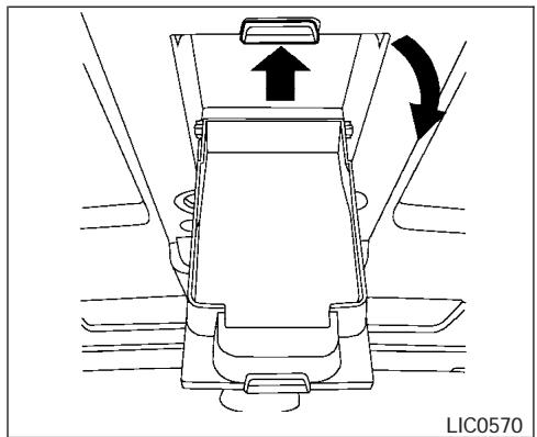
natural_image
Technical diagram of a car seatbelt with directional arrows indicating movement (no text or symbols)Large bin
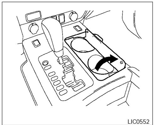
natural_image
Line drawing of a car interior showing a hand operating the intake manifold with a directional arrow indicating rotation (no text or symbols)Front
CUP HOLDERS
To open the front cup holders, lift the cup holder lid.
To close, lower the lid.

WARNING
The cup holder should not be used while driving so full attention may be given to vehicle operation.

CAUTION
- Avoid abrupt starting and braking when the cup holder is being used to prevent spilling the drink. If the liquid is hot, it can scald you or your passenger.
- Use only soft cups in the cup holder. Hard objects can injure you in an accident.
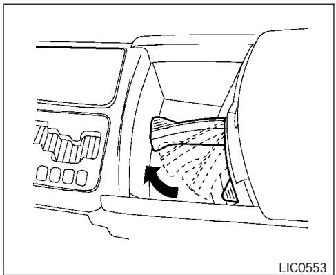
natural_image
Diagram of a car interior showing airflow or traffic flow through a vehicle, with no visible text or symbols.Adjustable
Position the arm on the adjustable cup holder so that the cup is held securely.
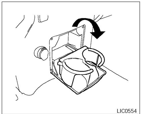
natural_image
Line drawing of a mechanical device with a rotating arrow and base plate, no text or symbols present2nd row (rear of front console)
To open the 2nd row cup holders (rear of the front console), lower the lid. To close, raise the lid.
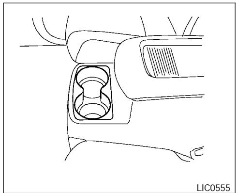
natural_image
Line drawing of a car interior showing the intake manifold and dashboard (no text or symbols)Rear console (if so equipped)
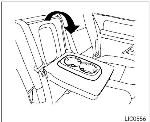
natural_image
Line drawing of a car interior showing a seatbelt with an arrow indicating rotation (no text or symbols)2nd row bench (if so equipped)
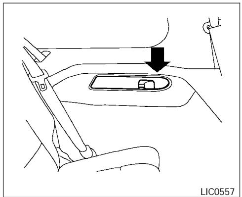
natural_image
Diagram of a car interior showing a seatbelt and directional arrow, no text or symbols present3rd row
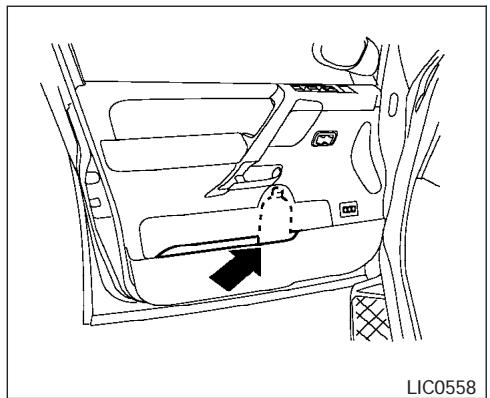
natural_image
Line drawing of a car interior with directional arrows and labeled component (no text or symbols beyond label)Bottle holder
CAUTION
- Do not use bottle holder for any other objects that could be thrown about in the vehicle and possibly injure people during sudden braking or an accident.
- Do not use bottle holder for open liquid containers.
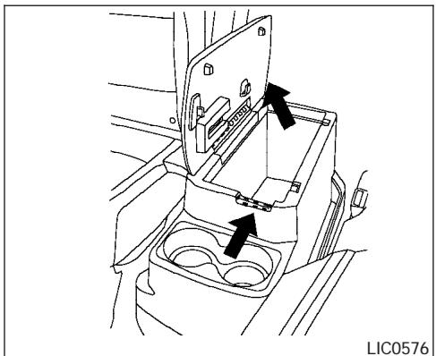
natural_image
Technical line drawing of a vehicle interior showing a car intake tray and internal compartments with arrows indicating movement (no text or symbols)2ND ROW CENTER CONSOLE (if so equipped)
Pull up on the lever to open the console box lid.
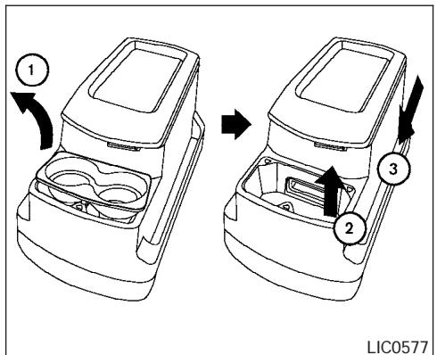
Removing the 2nd row center console box
To remove the 2nd row center console box:
① Lift out the cup holder tray.
② Pull up on the handle to tilt the console box up.
③ Move the console box toward the front of the vehicle and lift it out.
To reinstall the 2nd row center console box:
- Slide the console box over the base toward the rear of the vehicle.
- Push down to lock the console box in place.
- Replace the cup holder tray.
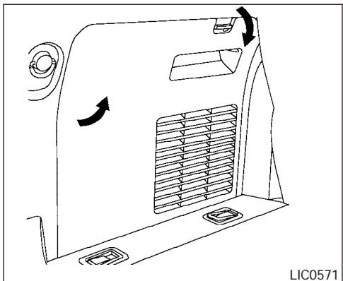
natural_image
Line drawing of a vehicle air vent with airflow direction arrows (no text or symbols)CARGO AREA STORAGE BIN
To open the cargo area storage bin, pull down on the tab and pull the lid off.

To access the floor storage area, push down ① to raise the handle, then pull up on the handle ② to lift the luggage board.
LUGGAGE HOOKS
The luggage hooks can be used to secure cargo with ropes or other types of straps.
WARNING
- Properly secure all cargo with ropes or straps to help prevent it from sliding or shifting. Do not place cargo higher than the seatbacks. In a sudden stop or collision, unsecured cargo could cause personal injury.
- Use suitable ropes and hooks to secure cargo.
- Never allow anyone to ride in the luggage area. It is extremely dangerous to ride in a cargo area inside of a vehicle. In a collision, people riding in these areas are more likely to be seriously injured or killed.
- Do not allow people to ride in any area of your vehicle that is not equipped with seats and seat belts.
- Be sure everyone in your vehicle is in a seat and using a seat belt properly.
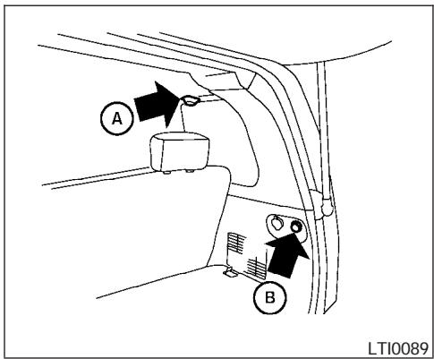
Side finisher
When hooking on ropes, do not apply a load of more than 55 lb (245 N) to a single Ⓐ hook or 44 lb (196 N) to a single Ⓑ hook.
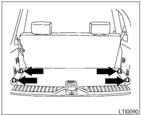
natural_image
Top-down diagram of a car's rearview and side-mounted air vent system (no text or symbols)Floor hooks
Do not apply a load of more than 110 lb (490 N) to a single hook.
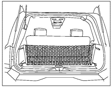
natural_image
Line drawing of a car backrest with internal compartments and a mesh chamber (no text or symbols)CARGO NET
The cargo net helps keep packages in the cargo area from moving around while the vehicle is in motion.
To install the cargo net, attach the hooks to the retainers.
To remove the cargo net, detach the hooks from the cargo net retainers.
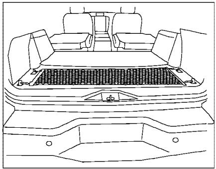
natural_image
Line drawing of a car rear view showing the roof, vent, and side compartments (no text or symbols)LIC0628

WARNING
- Properly secure all cargo to help prevent it from sliding or shifting. Do not place cargo higher than the seatbacks. In a sudden stop or collision, unsecured cargo could cause personal injury.
- Be sure to secure all four hooks into the retainers. The cargo restrained in the net must not exceed 30 lbs. (13.6 kg) or the net may not stay secured.
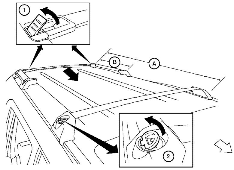
LIC0593
ROOF RACK
Always distribute the luggage evenly on the roof rack. Do not load more than 200 lbs (91 kg) on the entire roof rack A. If an additional rear crossbar (if so equipped) is installed, the maximum load capacity for the rear roof rack B is 125 lbs (56 kg). Be careful that your vehicle does not exceed the Gross Vehicle Weight Rating (GVWR) or its Gross Axle Weight Rating (GAWR front and rear). The GVWR and GAWR are located on the F.M.V.S.S. label (located on the driver's door pillar). For more information regarding GVWR and GAWR, refer to "Vehicle
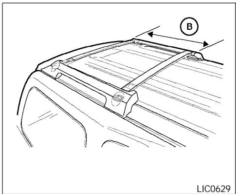
natural_image
Technical line drawing of a car front panel with mounting bracket and labeled component B (no text or symbols beyond label)Rear roof rack with additional crossbar (if so equipped)
loading information" in the "Technical and consumer information" section later in this manual.
The rear crossbar can be adjusted forward and backward. Raise the lock levers ① and adjust the crossbar to the desired position. Lower the lock levers. Place your luggage on the bars and secure the luggage with rope to the utility loops ②. Do not place luggage on the side rails or tie rope directly to the side rails. Always be sure the lock levers are lowered to keep the crossbar in place. Do not use utility loops for any purpose other than securing luggage.
WINDOWS

WARNING
Properly secure all cargo with ropes or straps to help prevent it from sliding or shifting. In a sudden stop or collision, unsecured cargo could cause personal injury.

CAUTION
Use care when placing or removing items from the roof rack. If you cannot comfortably lift the items onto the roof rack from the ground, use a ladder or stool.
POWER WINDOWS

WARNING
- Make sure that all passengers have their hands, etc. inside the vehicle while it is in motion and before closing the windows. Use the window lock switch to prevent unexpected use of the power windows.
- Do not leave children unattended inside the vehicle. They could unknowingly activate switches or controls and become trapped in a window. Unattended children could become involved in serious accidents.
The power windows operate when the ignition switch is in the ON position, or for about 45 seconds after the ignition switch is turned to the OFF position. If the driver's or passenger's door is opened during this period of about 45 seconds, power to the windows is canceled.
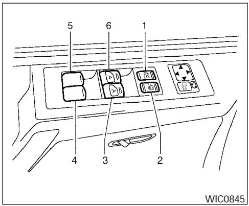
- Window lock button
- Power door lock switch
- Front passenger side automatic switch
- Right rear passenger window switch
- Left rear passenger window switch
- Driver side automatic switch
Driver's side power window switch
The driver's side control panel is equipped with switches to open or close the front and rear passenger windows.
To open a window, push the switch and hold it down. To close a window, pull the switch and hold it up. To stop the opening or closing function at any time, simply release the switch.
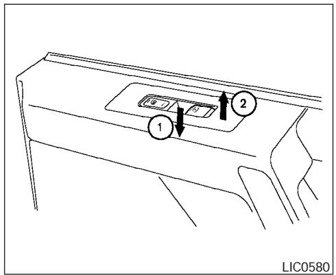
Front passenger power window switch
The passenger window switch operates only the corresponding passenger window. To open the window, push the switch and hold it down ①. To close the window, pull the switch up ②.
Locking passengers' windows
When the window lock button is depressed, only the driver side window can be opened or closed. Push it again to cancel the window lock function.
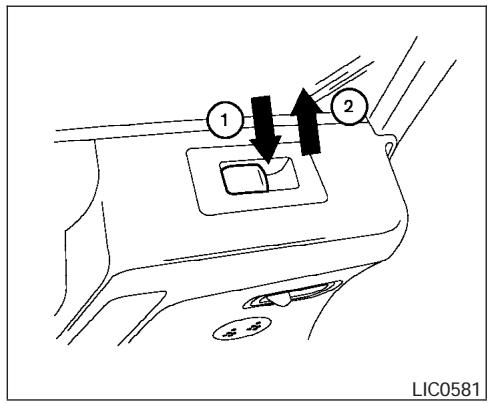
Rear power window switch
The rear passenger window switches open or close only the corresponding passenger window. To open the window, push the switch and hold it down ①. To close the window, pull the switch up ②.
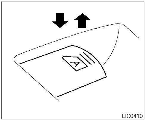
natural_image
Simple line drawing of a device with two arrows pointing downward and an arrow upward, no text or symbols present.Automatic operation
To fully open a window equipped with automatic operation, press the window switch down (only driver's side shown) to the second detent and release it; it need not be held. The window automatically opens all the way. To stop the window, lift the switch up while the window is opening.
To fully close a window equipped with automatic operation, pull the switch up to the second detent and release it; it need not be held.
Auto-reverse function
The auto-reverse function can be activated when a window is closed by automatic operation.
Depending on the environment or driving conditions, the auto-reverse function may be activated if an impact or load similar to something being caught in the window occurs.

WARNING
There are some small distances immediately before the closed position which cannot be detected. Make sure that all passengers have their hands, etc., inside the vehicle before closing the window.
If the control unit detects something caught in a window equipped with automatic operation as it is closing, the window will be immediately lowered.
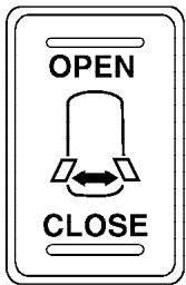
WIC0675
POWER VENT WINDOWS (if so equipped)
Use the vent window switch located on the overhead console to open and close the power vent windows. The windows cannot be operated separately.
To open the power vent windows, press and hold the switch toward OPEN.
To close the windows, press and hold the switch toward CLOSE.
The power vent windows operate when the ignition key is in the ON position, or for about 45 seconds after the ignition key is turned to the
OFF position. If the driver's or passenger's door is opened during this 45 second period, power to the vent windows is cancelled.
SUNROOF (if so equipped)
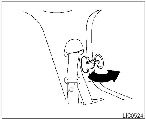
natural_image
Line drawing of a car seatbelt buckle with a black arrow indicating rotation (no text or symbols)MANUAL VENT WINDOWS (if so equipped)
To open a manual vent window, pull the latch handle toward you until it releases.
To lock the window in the open position, push the latch handle rearward until it locks.
To close a manual vent window, pull the latch handle toward you and push the rear portion of the latch toward the rear of the vehicle until it locks.
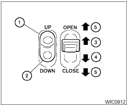
AUTOMATIC SUNROOF
The sunroof will only operate when the ignition key is in the ON position. The automatic sunroof is operational for about 45 seconds, even if the ignition key is turned to the ACC or OFF position. If the driver's door or the front passenger's door is opened during this period of about 45 seconds, power to the sunroof is canceled.
Sliding the sunroof
To fully open the sunroof, push the switch toward the open position ③.
To fully close the sunroof, push the switch toward the close position ④.
To open or close the sunroof part way, push the switch in any direction ⑤ while the roof is sliding open or closed to stop it in the desired position.
Tilting the sunroof
To tilt the sunroof up, push the tilt switch toward the up position ①. When the sunroof is open, it will automatically close and then tilt up.
To tilt the sunroof down, push the tilt switch toward the down position ②.
Restarting the sunroof sliding switch
The sliding switch will become inoperable after the battery terminal is disconnected, the electrical supply interrupted and/or some abnormality detected. Use the following reset procedure to return sunroof operation to normal.
- If the sunroof lid is open, push the tilting switch repeatedly toward the down position ② to fully close the lid.
- Finally, push and hold the tilting switch for more than 2 seconds toward the down position ② to reestablish the lid's home position.
The sunroof should now operate normally.
Auto reverse function (when closing or tilting down the sunroof)
The auto reverse function can be activated when the sunroof is closed or tilted down by automatic operation when the ignition key is in the ON position or for about 45 seconds after the ignition key is turned to the OFF position.
Depending on the environment or driving conditions, the auto reverse function may be activated if an impact or load similar to something being caught in the sunroof occurs.
WARNING
There are some small distances immediately before the closed position which cannot be detected. Make sure that all passengers have their hands, etc., inside the vehicle before closing the sunroof.
When closing:
If the control unit detects something caught in the sunroof as it moves to the front, the sunroof will immediately open backward.
When tilting down:
If the control unit detects something caught in the sunroof as it tilts down, the sunroof will immediately tilt up.
If the auto reverse function malfunctions and repeats opening or tilting up the sunroof, keep pushing the tilt down switch within 5 seconds after it happens, then the sunroof will fully close gradually. In this case, make sure nothing is caught in the sunroof.
WARNING
- In an accident you could be thrown from the vehicle through an open sunroof. Always use seat belts and child restraints.
- Do not allow anyone to stand up or extend any portion of their body out of the sunroof opening while the vehicle is in motion or while the sunroof is closing.
CAUTION
- Remove water drops, snow, ice or sand from the sunroof before opening.
- Do not place heavy objects on the sun-roof or surrounding area.
Sunshade
Open and close the sunshade by sliding it forward or backward.
If the sunroof does not close
Have your NISSAN dealer check and repair the sunroof.
INTERIOR LIGHT
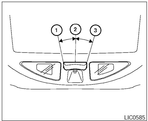
The interior light has a three-position switch and operates regardless of ignition switch position.
When the switch is in the ON position ①, the interior lights illuminate, regardless of door position. The lights will go off after about 30 minutes unless the ignition key is in the ACC or ON position.
When the switch is in the DOOR position ②, the interior lights and puddle lamps (if so equipped) will stay on for about 30 seconds when:
- The doors are unlocked by the keyfob, a key or the power door lock switch while all doors
are closed and the ignition switch is in the OFF position.
- The driver's door is opened and then closed while the key is removed from the ignition switch.
- The key is removed from the ignition switch while all doors are closed.
The lights will turn off while the 30 second timer is activated when:
- The driver's door is locked by the keyfob, a key, or the power door lock switch.
- The ignition switch is turned ON.
When the switch is in the OFF position ③, the interior lights do not illuminate, regardless of door position. The puddle lamps (if so equipped) come on when any front or rear passenger door is opened.
The lights will turn off automatically after 30 minutes while doors are open to prevent the battery from becoming discharged.
NOTE:
The footwell lights (if so equipped) and door step lights illuminate when the driver and passenger doors are open regardless of the interior light switch position. These lights will turn off automatically after about 30 minutes while doors are open to prevent the battery from becoming discharged.

CAUTION
Do not use for extended periods of time with the engine stopped. This could result in a discharged battery.
PERSONAL LIGHTS
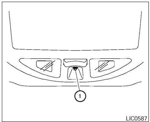
CONSOLE LIGHT
The console light ① will turn on whenever the parking lights or headlights are illuminated.
The console light brightness can be adjusted with the illumination brightness control.
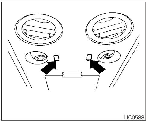
natural_image
Diagram showing two circular components with internal patterns and directional arrows, no text or symbols presentThe personal lights on the overhead console can be swiveled 360 degrees. To turn on the light, press the button. Press the button again to turn off the light.
MAP LIGHTS
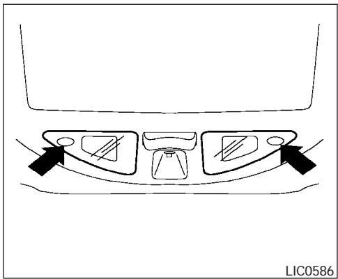
natural_image
Diagram of a car intake tray with three compartments and directional arrows indicating flow or movement (no text or symbols)To turn the map lights on, press the switches. To turn them off, press the switches again.

CAUTION
Do not use for extended periods of time with the engine stopped. This could result in a discharged battery.
HOMELINK® UNIVERSAL TRANSCEIVER
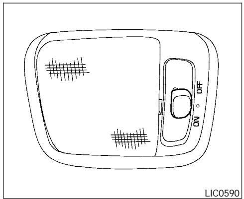
natural_image
Top-down line drawing of a device casing with grid patterns and ON/OFF labels (no text or symbols beyond basic markings)The cargo light on the overhead trim has a three-position switch. To operate, push the switch to the desired position.
ON: The light is illuminated.
Normal (center) position: The light illuminates when the back door or glass hatch is opened. The light turns off when the back door or glass hatch is closed.
OFF: The light does not illuminate regardless of door position or lock status.
The HomeLink® Universal Transceiver provides a convenient way to consolidate the functions of up to three individual hand-held transmitters into one built-in device.
HomeLink® Universal Transceiver:
- Will operate most Radio Frequency (RF) devices such as garage doors, gates, home and office lighting, entry door locks and security systems.
- Is powered by your vehicle's battery. No separate batteries are required. If the vehicle's battery is discharged or is disconnected, HomeLink® will retain all programming.
Once the HomeLink® Universal Transceiver is programmed, retain the original transmitter for future programming procedures (Example: new vehicle purchases). Upon sale of the vehicle, the programmed HomeLink® Universal Transceiver buttons should be erased for security purposes. For additional information refer to “Programming HomeLink®” later in this section.
WARNING
- Do not use the HomeLink® Universal Transceiver with any garage door opener that lacks safety stop and reverse features as required by federal safety standards. (These standards became effective for opener models manufactured after April 1, 1982). A garage door opener which cannot detect an object in the path of a closing garage door and then automatically stop and reverse, does not meet current federal safety standards. Using a garage door opener without these features increases the risk of serious injury or death.
- During the programming procedure your garage door or security gate will open and close (if the transmitter is within range). Make sure that people or objects are clear of the garage door, gate, etc. that you are programming.
- Your vehicle's engine should be turned off while programming the HomeLink® Universal Transceiver.
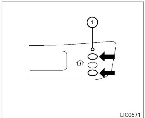
flowchart
graph TD
    A["1"] --> B
    B --> C
    C --> D
    D --> E
    E --> F
    F --> G
    G --> H
    H --> I
    I --> J
    J --> K
    K --> L
    L --> M
    M --> N
    N --> O
    O --> P
    P --> Q
    Q --> R
    R --> S
    S --> T
    T --> U
    U --> V
    V --> W
    W --> X
    X --> Y
    Y --> Z
    Z --> A
Type A
PROGRAMMING HOMELINK®
- To begin, press and hold the two outer HomeLink® buttons (to clear the memory) until the indicator light ① blinks slowly (after 20 seconds). Release both buttons.
- Position the end of the hand-held transmitter 1 - 3 inches (26 - 76 mm) away from the HomeLink® surface.
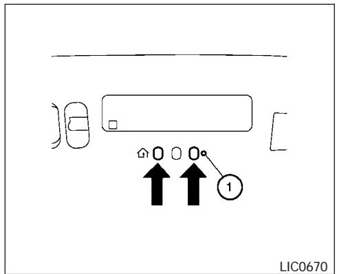
Type B
- Using both hands, simultaneously press and hold both the HomeLink® button you want to program and the hand-held transmitter button.
DO NOT release the buttons until step 4 has been completed.
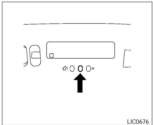
Type A
- Hold down both buttons until the indicator light on the HomeLink® flashes, changing from a "slow blink" to a "rapidly flashing blink". This could take up to 90 seconds. When the indicator light flashes rapidly, both buttons may be released. The rapidly flashing light indicates successful programming. To activate the garage door or other programmed device, press and hold the programmed HomeLink® button — releasing when the device begins to activate.
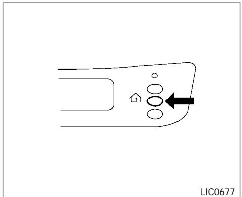
natural_image
Pure electrical circuit lines without any symbolsType B
-
If the indicator light on the HomeLink® blinks rapidly for 2 seconds and then turns solid, HomeLink® has picked up a “rolling code” garage door opener signal. You will need to proceed with the next steps to train the HomeLink® to complete the programming which may require a ladder and another person for convenience.
-
Press and release the “smart” or “learn” program button located on the garage door opener’s motor to activate the “training mode”. This button is usually located near the antenna wire that hangs down from the motor. If the wire originates from under a light lens, you will need to remove the lens to access the program button.
NOTE:
Once you have pressed and released the program button on the garage door opener's motor and the "training light" is lit, you have 30 seconds in which to perform step 7. Use the help of a second person for convenience to assist when performing this step.
-
Within 30 seconds of pressing and releasing the garage door opener program button, quickly and firmly press and release the HomeLink® button you've just programmed. Press and release the HomeLink® button up to 3 times to complete the training.
-
Your HomeLink ® button should now be programmed. (To program the remaining HomeLink ® buttons for additional door or gate openers, follow steps 2-8 only.)
NOTE:
Do not repeat step 1 unless you want to "clear" all previously programmed HomeLink® buttons.
If you have any questions or are having difficulty programming your HomeLink® buttons, refer to the HomeLink® web site at: www.homelink.com or call 1-800-355-3515.
PROGRAMMING HOMELINK® FOR CANADIAN CUSTOMERS
Prior to 1992, D.O.C. regulations required hand-held transmitters to stop transmitting after 2 seconds. To program your hand-held transmitter to HomeLink ® , continue to press and hold the HomeLink ® button (note steps 2 - 4 under “Programming HomeLink ® ”) while you press and repress (“cycle”) your hand-held transmitters every 2 seconds until the indicator light flashes rapidly (indicating successful programming).
NOTE:
When programming a garage door opener, etc., it is advised to unplug the device during the “cycling” process to prevent possible damage to the garage door opener components.
The HomeLink® Universal Transceiver (once programmed) may now be used to activate the garage door, etc. To operate, simply press the appropriate programmed HomeLink® Universal Transceiver button. The amber indicator light will illuminate while the signal is being transmitted.
PROGRAMMING TROUBLE-DIAGNOSIS
If the HomeLink ® does not quickly learn the handheld transmitter information:
- replace the hand-held transmitter batteries with new batteries.
- position the hand-held transmitter with its battery area facing away from the HomeLink® surface.
- press and hold both the HomeLink® and hand-held transmitter buttons without interruption.
- position the hand-held transmitter 1 - 3 inches (26 - 76 mm) away from the HomeLink® surface. Hold the transmitter in that position for up to 15 seconds. If HomeLink® is not programmed within that time, try holding the transmitter in another position – keeping the indicator light in view at all times.
If you continue to have programming difficulties, please contact the NISSAN Consumer Affairs Department. The phone numbers are located in the Foreword of this manual.
CLEARING THE PROGRAMMED INFORMATION
Individual buttons cannot be cleared. However, to clear all programming, press and hold the two outside buttons and release when the indicator light begins to flash (approximately 20 seconds).
REPROGRAMMING A SINGLE HOMELINK® BUTTON
To reprogram a HomeLink® Universal Transceiver button, complete the following.
- Press and hold the desired HomeLink® button. Do not release the button until step 4 has been completed.
- When the indicator light begins to flash slowly (after 20 seconds), position the hand-held transmitter 1 - 3 inches (26 - 76 mm) away from the HomeLink® surface.
-
Press and hold the hand-held transmitter button.
-
The HomeLink® indicator light will flash, first slowly and then rapidly. When the indicator light begins to flash rapidly, release both buttons.
The HomeLink® Universal Transceiver button has now been reprogrammed. The new device can be activated by pushing the HomeLink® button that was just programmed. This procedure will not affect any other programmed HomeLink® buttons.
IF YOUR VEHICLE IS STOLEN
If your vehicle is stolen, you should change the codes of any non-rolling code device that has been programmed into HomeLink®. Consult the Owner's Manual of each device or call the manufacturer or dealer of those devices for additional information.
When your vehicle is recovered, you will need to reprogram the HomeLink® Universal Transceiver with your new transmitter information.
FCC Notice:
This device complies with FCC rules part 15. Operation is subject to the following two conditions: (1) This device may not cause harmful interference and (2) This device must accept any interference that may be received, including interference that may cause undesired operation.
This transmitter has been tested and complies with FCC and DOC/MDC rules. Changes or modifications not expressly approved by the party responsible for compliance could void the user's authority to operate the device.
DOC: ISTC 1763K1313
FCC I.D. CV2V67690
3 Pre-driving checks and adjustments
Keys 3-2
Nissan vehicle immobilizer system (NVIS)
keys 3-2
Doors 3-3
Locking with key....3-3
Locking with inside lock knob 3-4
Locking with power door lock switch 3-4
Child safety rear door lock....3-5
Remote keyless entry system 3-5
How to use remote keyless entry system ..... 3-6
Hood 3-9
Back door 3-9
Operating the manual back door ....3-10
Operating the power back door
(if so equipped) 3-10
Cancel switch....3-12
Back door release 3-12
Glass hatch....3-14
Fuel filler lid....3-14
Fuel filler cap....3-14
Steering wheel 3-16
Tilt operation....3-16
Pedal position adjustment 3-16
Sun visors....3-17
Vanity mirrors 3-17
Mirrors 3-18
Automatic anti-glare inside mirror....3-18
Outside mirrors 3-18
Automatic drive positioner (if so equipped) .....3-19
Memory storage function 3-20
Entry/exit function 3-21
System operation....3-21
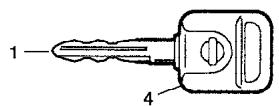
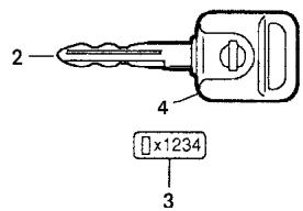
WPD0128
- Two master keys (black) with transponder chip and chrome NISSAN brand symbol on one side
- Valet key (black) with transponder chip
- Key number plate
- Transponder chip
A key number plate is supplied with your keys. Record the key number and keep it in a safe place (such as your wallet), not in the vehicle. If you lose your keys, see a NISSAN dealer for duplicates by using the key number. NISSAN does not record key numbers so it is very important to keep track of your key number plate.
A key number is only necessary when you have lost all keys and do not have one to duplicate from. If you still have a key, your NISSAN dealer can duplicate it.
NISSAN VEHICLE IMMOBILIZER SYSTEM (NVIS) KEYS
You can only drive your vehicle using the master or valet keys which are registered to the NISSAN Vehicle Immobilizer System components in your vehicle. These keys have a transponder chip in the key head.
The master key can be used for all the locks.
The valet key cannot be used for the console box lock.
To protect belongings when you leave a key with someone, give them the valet key only.
Never leave these keys in the vehicle.
Additional or replacement keys:
If you still have a key, the key number is not necessary when you need extra NISSAN Vehicle Immobilizer System keys. Your dealer can duplicate your existing key. As many as five NVIS keys can be used with one vehicle. You should bring all NVIS keys that you have to your NISSAN dealer for registration. This is because the registration process will erase the memory of all key codes
previously registered into the NISSAN Vehicle Immobilizer System. After the registration process, these components will only recognize keys coded into the NISSAN Vehicle Immobilizer System (NVIS) during registration. Any key that is not given to your dealer at the time of registration will no longer be able to start your vehicle.
Do not allow the immobilizer system key, which contains an electrical transponder, to come into contact with salt water. This could affect system function.
3-2 Pre-driving checks and adjustments
WARNING
- Always have the doors locked while driving. Along with the use of seat belts, this provides greater safety in the event of an accident by helping to prevent persons from being thrown from the vehicle. This also helps keep children and others from unintentionally opening the doors, and will help keep out intruders.
- Before opening any door, always look for and avoid oncoming traffic.
- Do not leave children unattended inside the vehicle. They could unknowingly activate switches or controls. Unattended children could become involved in serious accidents.
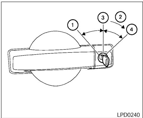
Driver's side
LOCKING WITH KEY
The power door lock system allows you to lock or unlock all doors at the same time.
Turning the key toward the front ① of the vehicle locks all doors.
Turning the key one time toward the rear ② of the vehicle unlocks that door. From that position, returning the key to neutral ③ (where the key can only be removed and inserted) and turning it toward the rear again within 5 seconds unlocks all doors ④.
Opening and closing windows
The driver's door key operation allows you to open and close windows equipped with automatic operation at the same time.
- To open the windows, turn the driver's door key toward the rear of the vehicle for longer than 1 second after the door is unlocked.
- To close the windows, turn the driver's door key to the front of the vehicle for longer than 1 second after the door is locked.
Windows stop when the key cylinder is released.
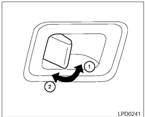
flowchart
graph TD
    A["Step 1"] --> B["Step 2"]
    B --> C["Arrow to Step 1"]
    style A fill:#f9f,stroke:#333
    style B fill:#ccf,stroke:#333
    style C fill:#cfc,stroke:#333
Inside lock
LOCKING WITH INSIDE LOCK KNOB
To lock the door without the key, move the inside lock knob to the lock position ①, then close the door.
To unlock the door without the key, move the inside lock knob to the unlock position ②.
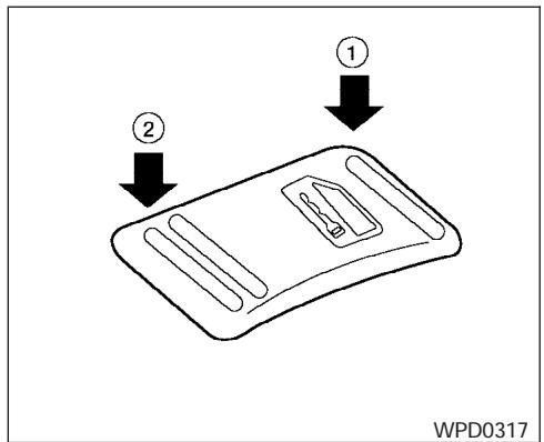
Door lock switch
LOCKING WITH POWER DOOR LOCK SWITCH
To lock all the doors without a key, push the door lock switch (driver or front passenger side), to the lock position ①. When locking the door this way, be certain not to leave the key inside the vehicle.
To unlock all the doors without a key, push the door lock switch (driver or front passenger side) to the unlock position ②.
Lockout protection
When the power door lock switch (driver's or front passenger's side) is moved to the lock position with the key in the ignition and any door open, all doors will lock and unlock automatically. This helps to prevent the keys from being accidentally locked inside the vehicle.
REMOTE KEYLESS ENTRY SYSTEM
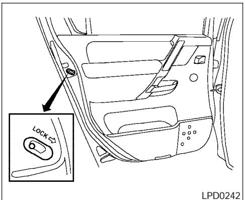
CHILD SAFETY REAR DOOR LOCK
Child safety locks help prevent the rear doors from being opened accidentally, especially when small children are in the vehicle.
The child safety lock levers are located on the edge of the rear doors.
When the lever is in the lock position, the door can be opened only from the outside.
It is possible to lock/unlock all doors, turn on the interior lights and puddle lamps (if so equipped), and activate the panic alarm by using the keyfob from outside the vehicle.
Some settings for the keyfob, such as horn beep, can be adjusted. For vehicles without navigation system, refer to “Silencing the horn beep feature” later in this section. For vehicles with navigation system, refer to “Vehicle electronic systems” in the “Display screen, heater, air conditioner and audio systems” section later in this manual.
Be sure to remove the key from the vehicle before locking the doors.
The keyfob can operate at a maximum distance of approximately 33 ft (10 m) from the vehicle. The effective distance depends upon the conditions around the vehicle.
As many as 5 keyfobs can be used with one vehicle. For information concerning the purchase and use of additional keyfobs, contact a NISSAN dealer.
The keyfob will not function when:
● the battery is discharged.
- the distance between the vehicle and the keyfob is over 33 ft (10 m).
The panic alarm will not activate when the key is in the ignition switch.

CAUTION
Listed below are conditions or occurrences which will damage the keyfob:
- Do not allow the keyfob to become wet.
- Do not drop the keyfob.
- Do not strike the keyfob sharply against another object.
- Do not place the keyfob for an extended period in an area where temperatures exceed 140irc F ( 60irc C).
If a keyfob is lost or stolen, NISSAN recommends erasing the ID code of that keyfob. This will prevent the keyfob from unauthorized use to unlock the vehicle. For information regarding the erasing procedure, please contact a NISSAN dealer.
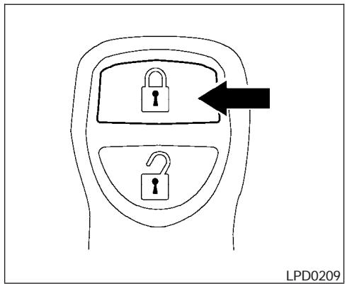
HOW TO USE REMOTE KEYLESS ENTRY SYSTEM
Locking doors
- Close all windows.
- Remove the key from the ignition switch.
- Close the hood and all doors.
-
Push the 🔊 button on the keyfob. All the doors lock. The hazard warning lights flash twice and the horn beeps once to indicate all doors are locked.
-
When the 🔒 button is pushed with all doors locked, the hazard warning lights flash twice and the horn beeps once as a reminder that the doors are already locked.
- If a door is open and you push the button, the doors will lock but the horn will not beep and the hazard warning lights will not flash.
The horn may or may not beep. For vehicles without navigation system, refer to “Silencing the horn beep feature” later in this section. For vehicles with navigation system, refer to “Vehicle electronic systems” in the “Display screen, heater, air conditioner and audio systems” section later in this manual.
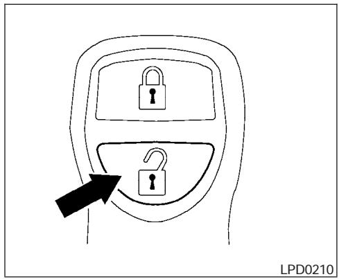
Unlocking doors
Push the 🔒 button on the keyfob once.
- Only the driver's door unlocks.
- The hazard warning lights flash once if all doors are completely closed with the ignition key in any position except the ON position.
- The interior lights and puddle lamps (if so equipped) turn on and the light timer activates for 30 seconds when the interior light switch is in the DOOR position with the ignition key in any position except the ON position.
Push the 🔒 button on the keyfob again within 5 seconds.
- All doors unlock.
- The hazard warning lights flash once if all doors are completely closed.
The interior lights can be turned off without waiting 30 seconds by inserting the key into the ignition and turning to the ON or START position, locking the doors with the keyfob or pushing the interior light switch to the off position.
Auto relock
When the 🔒 button on the keyfob is pushed, all doors will lock automatically within 1 minute unless one of the following operations is performed:
- Any door is opened.
- A key is inserted into the ignition switch and the key is turned from OFF to ON.
Opening windows
The keyfob allows you to open windows equipped with automatic operation simultaneously.
- To open the windows, press the ☐ button on the keyfob for longer than 3 seconds after all doors are unlocked.
The door windows will open while pressing the 🔒 button on the keyfob.
The door windows cannot be closed by using the keyfob.
Linking the keyfob to automatic drive positioner memory
If the vehicle is equipped with automatic drive positioner, the keyfob can be linked to a memory setting.
See “Automatic driver positioner” later in this section.
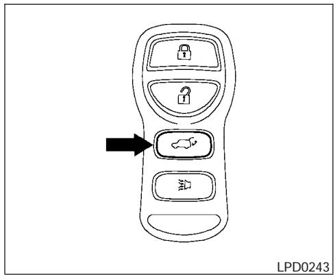
Operating the power back door (if so equipped)
Push and hold the button on the keyfob for about 0.5 second to open or close the back door. The hazard warning lights flash and a chime sounds to indicate the power open or power close sequence has started.
The door will reverse direction immediately during power open or power close if the keyfob button is pressed. A chime will sound to announce the reversal.
For more information, see "Back door" later in this section.
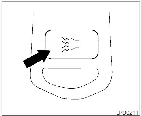
Using the panic alarm
If you are near your vehicle and feel threatened, you may activate the panic alarm to call attention by pushing and holding the ☑ button on the keyfob for longer than 0.5 second.
The panic alarm and headlights will stay on for 25 seconds.
The panic alarm stops when:
- it has run for 25 seconds, or
- any button is pushed on the keyfob.
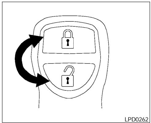
flowchart
graph TD
    A["Lock Icon"] --> B["Lock Icon"]
    B --> C["Downward Arrow"]
    style A fill:#f9f,stroke:#333
    style B fill:#ccf,stroke:#333
    style C fill:#cfc,stroke:#333
Silencing the horn beep feature
If desired, the horn beep feature can be deactivated using the keyfob.
NOTE:
If you change the horn beep and lamp flash feature with the keyfob, the display screen (if so equipped) will not show the current mode and cannot be used to change the mode. Use the keyfob to return to the previous mode and re-enable the display screen control.
To deactivate: Press and hold the and 🔒 buttons for at least 2 seconds.
The hazard warning lights will flash three times to confirm that the horn beep feature has been deactivated.
To activate: Press and hold the 🔒 and 🔒 buttons for at least 2 seconds once more.
The hazard warning lights will flash once and the horn will sound once to confirm that the horn beep feature has been reactivated.
Deactivating the horn beep feature does not silence the horn if the alarm is triggered.
Using the interior lights
Push the 🔒 button on the keyfob once to turn on the interior lights and puddle lamps (if so equipped).
For additional information, refer to “Interior light” in the “Instruments and controls” section earlier in this manual.
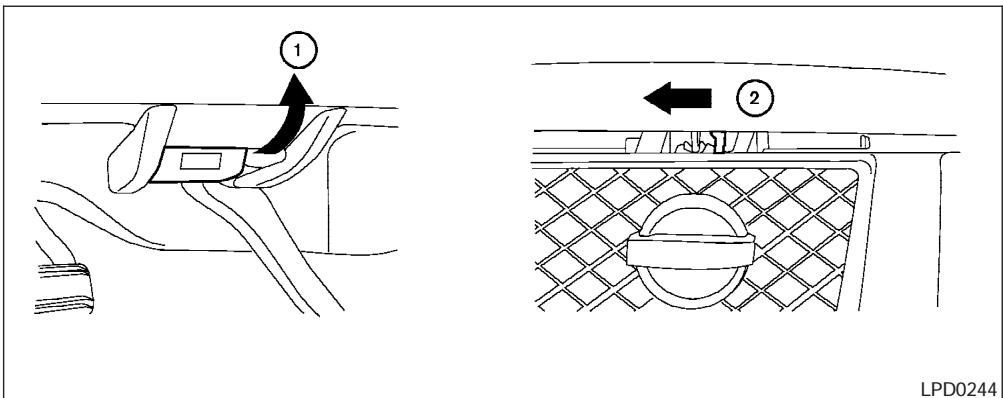
① Pull the hood lock release handle located below the driver side instrument panel. The hood will spring up slightly.
② Push the lever at the front of the hood to the side as illustrated with your fingertips and raise the hood.
When closing the hood, lower it slowly and make sure it locks into place.
- Make sure the hood is completely closed and latched before driving. Failure to do so could cause the hood to fly open and result in an accident.
- If you see steam or smoke coming from the engine compartment, to avoid injury do not open the hood.
WARNING
WARNING
- Always be sure the back door has been closed securely to prevent it from opening while driving.
- Do not drive with the back door open. This could allow dangerous exhaust gases to be drawn into the vehicle. See "Exhaust gas" in the "Starting and driving" section of this manual.
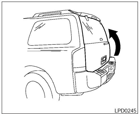
natural_image
Line drawing of a vehicle rear view showing the side profile and side door (no text or symbols)Make sure that all passengers have their hands, etc. inside the vehicle before closing the back door.
The power door lock system allows you to lock or unlock all doors including the back door simultaneously.
To open the back door, pull up on the handle.
To close, lower and push the back door down securely.
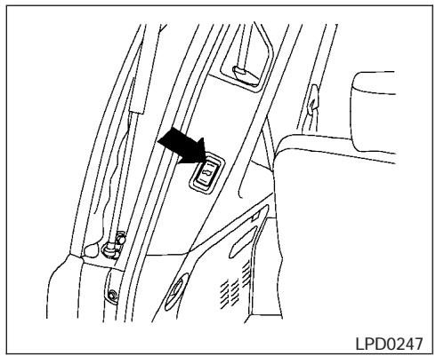
natural_image
Line drawing of a car interior showing seatbelt and door panel (no text or symbols)Rear pillar switch
- Make sure that all passengers have their hands, etc. inside the vehicle before closing the back door.
- Do not leave children unattended inside the vehicle. They could unknowingly activate switches or controls. Unattended children could become involved in serious accidents.
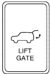
LPD0283
Instrument panel switch
NOTE:
To open, close or reverse the power back door, the shift selector lever must be in P (Park). Also, the power back door will not operate if battery voltage is low.
Power Open:
The power back door automatically moves from the fully closed position to the fully open position in approximately 5 – 8 seconds. The power open feature can be activated by the switch on the keyfob, the instrument panel switch and by the outside opener handle. The hazard lights flash
and a chime sounds to indicate the power open sequence has been started.
- The back door can be opened by the instrument panel switch and the keyfob even if the vehicle is locked. The door will individually unlock and open. Once the back door is closed, its lock will align to the vehicle's lock or unlock status.
- The keyfob button must be held for 0.5 second before the door opens.
- The back door must be unlocked to open it with the outside opener handle.
- The switch on the rear pillar cannot be used to open the back door.
A warning chime will sound if the shift selector lever is moved out of P (Park) during a power open operation.
Power Close:
The power back door automatically moves from the fully open position to the secondary position. When the door reaches the secondary position, the cinching motor engages and pulls the door to its primary latch position. Power close takes approximately 7 – 10 seconds. The power close feature can be activated by the switch on the keyfob, the instrument panel and the rear pillar. The hazard lights flash and a chime sounds to indicate the power close sequence has been started.
- If the outside opener handle is activated while the cinching motor is engaged, the cinching motor will disengage and release the latch.
- The keyfob button must be held for 0.5 second before the door closes.
- The switch on the rear pillar can only be used to close the back door if the cancel switch is not in the on position.
Reverse:
The power back door will reverse direction immediately during power open or power close if the keyfob, instrument panel or rear pillar switch is pressed or if the outside handle is lifted. A chime will sound to announce the reversal.
Auto Reverse:
If an obstacle is detected during power open or power close, a warning chime will sound and the door will reverse direction and return to the full open or full close position. If a second obstacle is detected, the door motion will stop and the drive motor will disengage. The back door will enter manual mode. A pinch strip is mounted on each side of the back door. If an obstacle is detected by a pinch strip during power close, the door will reverse direction and return to the full open position.
NOTE:
If the pinch strip is damaged or removed, the power close function will not operate.

WARNING
There are some small distances immediately before the closed position which cannot be detected. Make sure that all passengers have their hands, etc., inside the vehicle before closing the door.
Manual Mode:
If power operation is not available, the back door may be operated manually. Power operation may not be available if the cancel switch is in the on position, if multiple obstacles have been detected in a single power cycle, or if battery voltage is low.
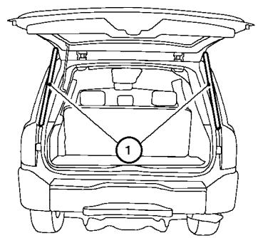
natural_image
Line drawing of a car trunk with a numbered component (1) on the rear, showing structural layout without any text or symbols.LPD0250
Safe Mode:
If the back door gas stays ① lose pressure, the power back door safe mode is activated. When the safe mode is activated, the back door slowly closes. A continuous warning chime sounds until the door is in the fully down position. Then the door will be pulled to the closed and latched position by a motor.
The power back door cannot be opened using the switches at any time in the safe mode.
The auto reverse function remains active while the door is closing in the safe mode.
Do not operate the back door again until it is checked by your NISSAN dealer.
CAUTION
- If the power back door does not stay open or if the door unexpectedly closes at any time while a continuous warning chime sounds, do not operate the back door. There may be a pressure loss in one or both of the back door gas stays. Have the back door inspected by a NISSAN dealer.
- Do not activate the power back door if one or both of the back door gas stays are removed. Damage to the back door or power back door mechanisms may occur.
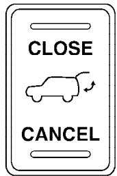
LPD0248
CANCEL SWITCH
Press the switch toward the CANCEL position to disable the rear pillar switch. The back door can still be opened and closed using the switch on the instrument panel and keyfob. The back door can also be opened manually with the outside handle if the door is unlocked.
BACK DOOR RELEASE
WARNING
- Always be sure the back door has been closed securely to prevent it from opening while driving.
3-12 Pre-driving checks and adjustments
- Do not drive with the back door open. This could allow dangerous exhaust gases to be drawn into the vehicle. See "Exhaust gas" in the "Starting and driving" section of this manual.

CAUTION
- If the power back door does not stay open or if the door unexpectedly closes at any time while a continuous warning chime sounds, do not operate the back door. There may be a pressure loss in one or both of the back door gas stays. Have the back door inspected by a NISSAN dealer.
- Do not activate the power back door if one or both of the back door gas stays are removed. Damage to the back door or power back door mechanisms may occur.
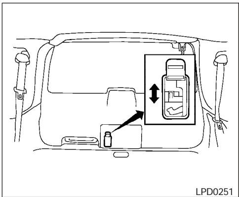
Manual back door release
Manual back door (if so equipped)
If the back door cannot be locked or unlocked with the door lock switch or the keyfob due to a discharged battery, follow these steps:
- Remove the cover on the inside of the back door.
- Move the lever up to lock or down to unlock.
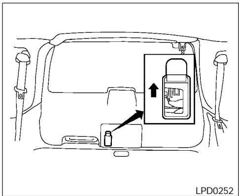
Power back door release
Power back door (if so equipped)
If the back door cannot be opened with the door lock switch or keyfob due to a discharged battery, follow these steps:
- Remove the cover on the inside of the back door.
- Move the lever up to open the door.
GLASS HATCH
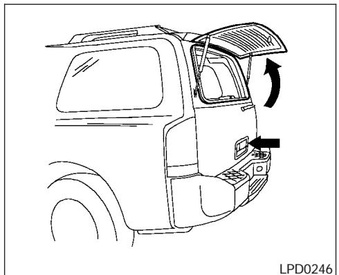
natural_image
Line drawing of a truck's rear window and side door, showing no text or symbolsTo open, pull up on the smaller outside handle to release the glass hatch, then pull up on the glass hatch. To close, lower and push the glass hatch down securely.
NOTE:
The back door must be unlocked in order to open the glass hatch.

WARNING
Do not drive with the glass hatch open. This could allow dangerous exhaust gases to be drawn into the vehicle. See “Exhaust gas” in the “Starting and driving” section of this manual.
FUEL FILLER LID
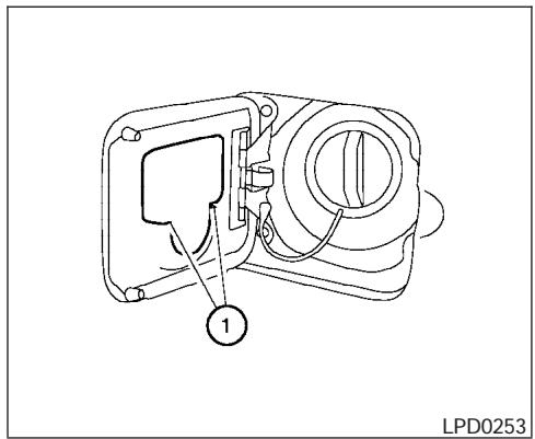
FUEL FILLER CAP
The fuel filler cap is a ratcheting type. Turn the cap counterclockwise to remove. To tighten, turn the cap clockwise until ratcheting clicks are heard.
Put the fuel filler cap on the cap holder ① while refueling.
WARNING
- Gasoline is extremely flammable and highly explosive under certain conditions. You could be burned or seriously injured if it is misused or mishandled. Always stop the engine and do not smoke or allow open flames or sparks near the vehicle when refueling.
- Fuel may be under pressure. Turn the cap a third of a turn, and wait for any "hissing" sound to stop to prevent fuel from spraying out and possibly causing personal injury. Then remove the cap.
- Do not attempt to top off the fuel tank after the fuel pump nozzle shuts off automatically. Continued refueling may cause fuel overflow, resulting in fuel spray and possibly a fire.
- Use only an original equipment type fuel filler cap as a replacement. It has a built-in safety valve needed for proper operation of the fuel system and emission control system. An incorrect cap can result in a serious malfunction and possible injury. It could also cause the malfunction indicator lamp to come on.
-
Never pour fuel into the throttle body to attempt to start your vehicle.
-
Do not fill a portable fuel container in the vehicle or trailer. Static electricity can cause an explosion of flammable liquid, vapor or gas in any vehicle or trailer. To reduce the risk of serious injury or death when filling portable fuel containers:
- Always place the container on the ground when filling.
- Do not use electronic devices when filling.
- Keep the pump nozzle in contact with the container while you are filling it.
- Use only approved portable fuel containers for flammable liquid.
CAUTION
- If fuel is spilled on the vehicle body, flush it away with water to avoid paint damage.
- Tighten until the fuel filler cap clicks. Failure to tighten the fuel filler cap properly may cause the SERVICE ENGINE SOON malfunction indicator lamp (MIL) to illuminate. If the SERVICE ENGINE SOON lamp illuminates because the fuel filler cap is loose or missing, tighten or install the cap and continue to drive the vehicle. The SERVICE ENGINE SOON lamp should turn off after a few driving trips. If the SERVICE ENGINE SOON lamp does not turn off after a few driving trips, have the vehicle inspected by a NISSAN dealer.
- For additional information, see the "Malfunction indicator lamp (MIL)" in the "Instruments and Controls" section earlier in this manual.
STEERING WHEEL
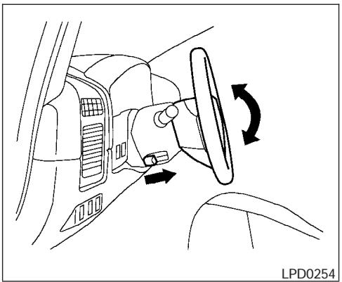
natural_image
Diagram of a car interior showing steering wheel and dashboard with directional arrows indicating rotation (no text or symbols)TILT OPERATION
Pull the lock lever forward and hold it to adjust the steering wheel up or down to the desired position.
Release the lock lever to lock the steering wheel in place.

WARNING
Do not adjust the steering wheel while driving. You could lose control of your vehicle and cause an accident.
PEDAL POSITION ADJUSTMENT
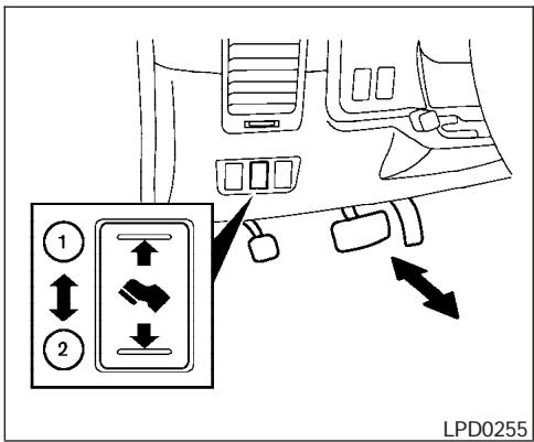
The accelerator and brake pedals can be adjusted for driving comfort.
Use the pedal adjusting switch to adjust the brake and accelerator pedal position forward ① or backward ②. Pedal adjustment can only be performed when:
- Ignition switch is in the OFF or ACC position
- Ignition switch is ON and the selector lever is in the P (Park) position
The brake and accelerator pedals cannot be adjusted separately.

CAUTION
Do not adjust the pedal position with your foot on the pedal.
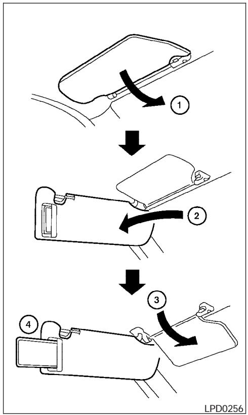
flowchart
graph TD
    A["Opening Seatbelt"] --> B["Cut to Cover"]
    B --> C["Car Strel"]
    C --> D["Car Pulling to Cover"]
    D --> E["Car Strel with Pulling to Cover"]
① To block glare from the front, swing down the main sun visor.
② To block glare from the side, remove the main sun visor from the center mount and swing the visor to the side.
③ To block glare from the side and front, swing down the sub-sun visor.
④ Slide the extension sun visor in or out as needed.
CAUTION
- Do not store the sun visor before returning the extension to its original position.
- Do not pull the extension sun visor forcedly downward.
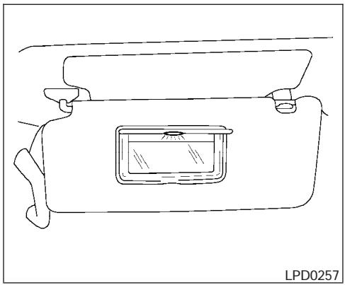
natural_image
Line drawing of a rectangular container with a central display and side handles (no text or symbols)VANITY MIRRORS
To access the vanity mirror, pull the sun visor down and flip open the mirror cover. The vanity mirror will illuminate when the mirror cover is open.
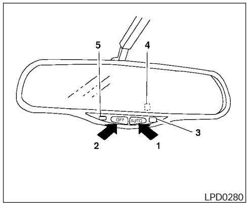
- AUTO position
- OFF position
- AUTO indicator light
- Sensor (on back of mirror)
- Sensor
AUTOMATIC ANTI-GLARE INSIDE MIRROR
The inside mirror is designed so that it automatically changes reflection according to the intensity of the headlights of the vehicle following you.
When the inside mirror switch is in the AUTO position, excessive glare from the headlights of the vehicle behind you will be reduced. The
AUTO indicator light will be on. When the switch on the inside mirror is in the OFF position, the inside mirror will operate normally.
Do not hang any object on the sensor or apply glass cleaner. Doing so will reduce the sensitivity of the sensor, resulting in improper operation.
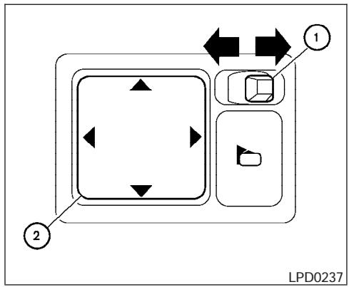
flowchart
graph TD
    A["1"] --> B["2"]
    B --> C["3"]
    C --> D["4"]
    D --> E["5"]
    E --> F["6"]
    F --> G["7"]
    G --> H["8"]
    H --> I["9"]
    I --> J["10"]
    style A fill:#f9f,stroke:#333
    style J fill:#bbf,stroke:#333
OUTSIDE MIRRORS
The outside mirror remote control will operate only when the ignition switch is in the ACC or ON position.
Move the small switch ① to select the right or left mirror. Adjust each mirror to the desired position using the large switch ②.

WARNING
- Objects viewed in the outside mirror on the passenger side are closer than they appear. Be careful when moving to the right. Using only this mirror could cause an accident. Use the inside mirror or glance over your shoulder to properly judge distances to other objects.
- Do not adjust the mirrors while driving. You could lose control of your vehicle and cause an accident.
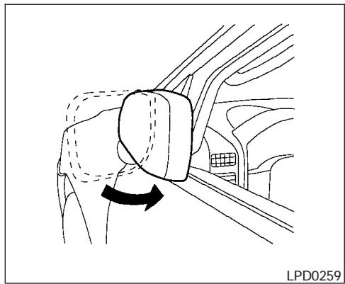
natural_image
Diagram of a car's side arm and seat assembly, showing a curved arrow indicating rotation (no text or symbols)Foldable outside mirrors
Pull the outside mirror toward the door to fold it.
Heated mirrors
The outside mirrors can be heated to defrost, defog, or de-ice for improved visibility. For additional information, see “Rear window and outside mirror defroster switch” in the “Instrument and controls” section of this manual.
AUTOMATIC DRIVE POSITIONER (if so equipped)
The automatic drive positioner system has two features:
● Memory storage function
- Entry/exit function
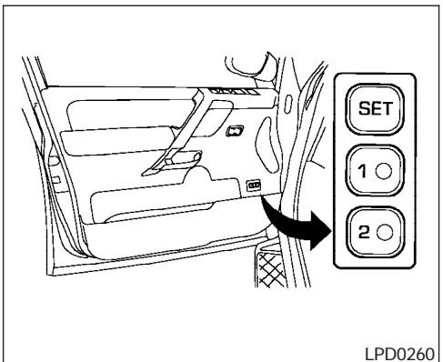
MEMORY STORAGE FUNCTION
Two positions for the driver's seat, accelerator and brake pedals, and outside mirrors can be stored in the automatic drive positioner memory. Follow these procedures to use the memory system.
- Set the automatic transmission selector lever to the P (Park) position.
-
Turn the ignition ON.
-
Adjust the driver's seat, accelerator and brake pedals, and outside mirrors to the desired positions by manually operating each adjusting switch. For additional information, see "Seats" in the "Safety—Seats, seat belts and supplemental restraint system" section and "Pedal position adjustment" and "Outside mirrors" earlier in this section.
During this step, do not turn the ignition to any position other than ON.
- Push the SET switch and, within 5 seconds, push the memory switch (1 or 2) fully for at least 1 second.
The indicator light for the pushed memory switch will come on and stay on for approximately 5 seconds after pushing the switch. After the indicator light goes off, the selected positions are stored in the selected memory (1 or 2).
If a new memory is stored in the same memory switch, the previous memory will be deleted.
Linking a keyfob to a stored memory position
Each keyfob can be linked to a stored memory position (memory switch 1 or 2) with the following procedure.
- Follow the steps for storing a memory position.
- While the indicator light for the memory switch being set is illuminated for 5 seconds, press the ⏻ button on the keyfob. The indicator light will blink. After the indicator light goes off, the keyfob is linked to that memory setting.
With the key removed from the ignition switch, press the 🔒 button on the keyfob. The driver's seat, accelerator and brake pedals, and outside mirrors will move to the memorized position.
NOTE:
If a new memory is saved to the memory switch, the keyfob must be re-linked.
Confirming memory storage
- Turn the ignition ON and push the SET switch. If the main memory has not been stored, the indicator light will come on for approximately 0.5 seconds. When the memory has stored the position, the indicator light will stay on for approximately 5 seconds.
-
If the battery cable is disconnected, or if the fuse opens, the memory will be canceled. In such a case, reset the desired positions using the following procedures.
-
Open and close the driver's door more than two times with the ignition key in the LOCK position.
-
Reset the desired position using the previous procedure.
Selecting the memorized position
- Set the automatic transmission selector lever to the P (Park) position.
- Turn the ignition ON.
- Push the memory switch (1 or 2) fully for at least 1 second.
The driver's seat, accelerator and brake pedals, and outside mirrors will move to the memorized position with the indicator light blinking, and then the light will stay on for approximately 5 seconds.
ENTRY/EXIT FUNCTION
This system is designed so that the driver's seat will automatically move when the automatic transmission selector lever is in the P (Park) position. This allows the driver to get into and out of the driver's seat more easily.
The driver's seat will slide backward:
- When the driver's door is opened with the ignition key turned to LOCK.
- When the ignition key is turned from ACC to LOCK with the driver's door open while the automatic transmission selector lever is in the P (Park) position.
The driver's seat will return to the previous position:
- When the key is inserted into the ignition switch.
- When the driver's door is closed with the key turned to LOCK.
- When the key is turned from ACC to ON while the automatic transmission selector lever is in the P (Park) position.
The entry/exit function can be adjusted or canceled. For vehicles with navigation system, see "Vehicle electronic systems" in the "Display screen, heater, air conditioner and audio systems" section of this manual. For vehicles without navigation system, see your NISSAN dealer.
SYSTEM OPERATION
The automatic drive positioner system will not work or will stop operating under the following conditions:
- When the vehicle speed is above 4 MPH (7 km/h).
- When any two or more of the memory switches are simultaneously pushed while the automatic drive positioner is operating.
- When the adjusting switch for the driver's seat is turned on while the automatic drive positioner is operating.
- When the memory switch (1 or 2) is not pushed for at least 1 second.
- When the seat has been already moved to the memorized position.
- When no seat position is stored in the memory switch.
The automatic drive positioner system can be adjusted and canceled. For vehicles with navigation system, see “Vehicle electronic systems” in the “Display screen, heater, air conditioner and audio systems” section of this manual. For vehicles without navigation system, see your NISSAN dealer.
4 Display screen, heater, air conditioner and audio systems
Control panel buttons (if so equipped) 4-2
Names of the components.... 4-3
How to use joystick and "ENTER" button....4-3
How to use "PREV" button 4-3
Setting up the start-up screen 4-3
How to use the "TRIP" button 4-4
How to use the "SETTING" button....4-7
Setting the display (Audio or HVAC display): ..... 4-7
☀/☐ button....4-12
Rearview monitor (if so equipped)....4-12
How to read the displayed lines .....4-12
Adjusting the screen....4-13
Operating tips....4-13
Ventilators 4-14
Heater and air conditioner (manual)....4-15
Controls....4-15
Heater operation 4-16
Air conditioner operation 4-18
Air flow charts....4-19
Heater and air conditioner (automatic)
(if so equipped) 4-24
Automatic operation 4-24
Manual operation....4-25
Rear control button 4-26
Operating tips....4-26
Rear seat air conditioner 4-27
Controls....4-27
Servicing air conditioner....4-27
Audio system 4-28
Radio 4-28
FM radio reception 4-28
AM radio reception 4-28
Satellite radio reception (if so equipped) .....4-28
Audio operation precautions 4-29
FM-AM-SAT radio with compact disc changer (Type A and B) (if so equipped) .....4-31
CD care and cleaning....4-37
Steering wheel switch for audio control (if so equipped) 4-37
Rear audio controls (if so equipped) 4-39
Antenna 4-40
NISSAN mobile entertainment system (MES)
(if so equipped) 4-40
Digital video disc (DVD) player controls .....4-41
Remote control....4-42
Flip-down screen....4-42
Playing a digital video disc (DVD) 4-44
Care and maintenance 4-47
How to handle the DVD 4-47
Car phone or CB radio....4-50
CONTROL PANEL BUTTONS (if so equipped)

WARNING
- Positioning of the heating or air conditioning controls and display controls should not be done while driving in order that full attention may be given to the driving operation.
- Do not disassemble or modify this system. If you do, it may result in accidents, fire, or electrical shock.
- Do not use this system if you notice any abnormality, such as a frozen screen or lack of sound. Continued use of the system may result in accident, fire or electric shock.
- In case you notice any foreign object in the system hardware, spill liquid on it, or notice smoke or smell coming from it, stop using the system immediately and contact your nearest NISSAN dealer. Ignoring such conditions may lead to accidents, fire or electrical shock.
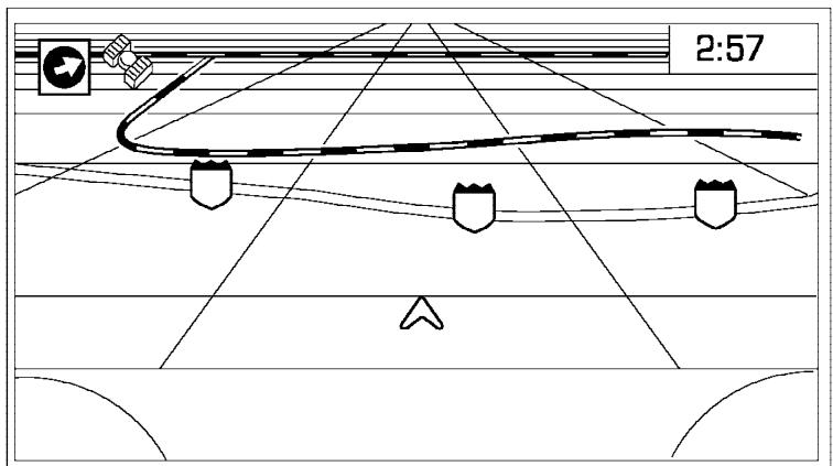
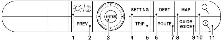
LHA0388
When you use this system, make sure the engine is running.
If you use the system with the engine not running (ignition ON or ACC) for a long time, it will use up all the battery power, and the engine will not start.
Reference symbols:
"ENTER" button — This is a button on the control panel.
"Display" key — This is a select key on the screen. By selecting this key you can proceed to the next function.
4-2 Display screen, heater, air conditioner and audio systems
NAMES OF THE COMPONENTS
- ⚙/∅ brightness control button (P. 4-12)
- PREV (previous) button (P. 4-3)
- Joystick and ENTER push button (P. 4-3)
- SETTING button (P. 4-7)
- TRIP drive computer button (P. 4-4)
- DEST button*
- ROUTE button*
- MAP button*
-
GUIDE VOICE button*
-
☒ zoom out button*
-
☐ zoom in button*
*For Navigation system control buttons, refer to the separate Navigation System Owner's Manual.
HOW TO USE JOYSTICK AND "ENTER" BUTTON
Choose an item on the display using the joystick and push the "ENTER" button for operation.
HOW TO USE "PREV" BUTTON
This button has two functions.
- Go back to the previous display (cancel).
If you touch "PREV" button during setup, the setup will be canceled and/or the display will return to the previous screen.
- Finish setup.
If you touch this button after the setup is completed, the setup will start over, and the display will return to the climate control or audio mode and Navigation screen.
SETTING UP THE START-UP SCREEN
When you turn the ignition key to ACC or ON, the SYSTEM START-UP warning is displayed on the screen. Read the warning and select the "I AGREE" (English) or "ENTER" (Français) key then push the "ENTER" button.
If you do not push the "ENTER" button, the Navigation system will not proceed to the next step display.
If you do not touch the button or screen key for more than 1 minute on the TRIP, SETTING or START-UP screen, the screen will change to TRIP screen automatically.
To proceed to the next step, refer to the separate Navigation System Owner's Manual.
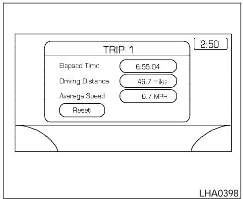
HOW TO USE THE "TRIP" BUTTON
When the "TRIP" button is pushed, the following modes will display on the screen.
Warning message (if there are any) → TRIP 1 (Elapsed Time, Driving Distance, Average Speed) → TRIP 2 → FUEL ECONOMY (Average Fuel Economy, Distance to Empty) → MAINTENANCE (Engine Oil, Tire Rotation and Tire Pressure — if so equipped) → OFF.
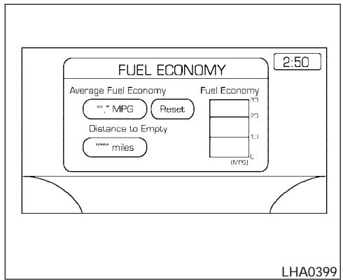
Trip 1, trip 2 and fuel economy items
To reset the TRIP 1, TRIP 2 and FUEL ECONOMY, select the "RESET" key using the joystick and push the "ENTER" button or push the "TRIP" button for more than approximately 1.5 seconds.
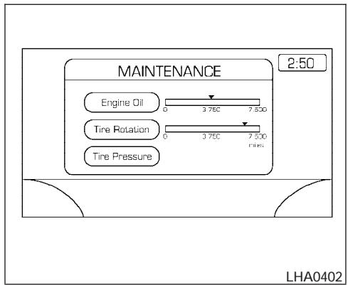
Maintenance items
You can set the engine oil and the tire rotation interval.
To display the setting of the maintenance interval, select the “Engine Oil” or “Tire Rotation” key using the joystick and push the “ENTER” button.
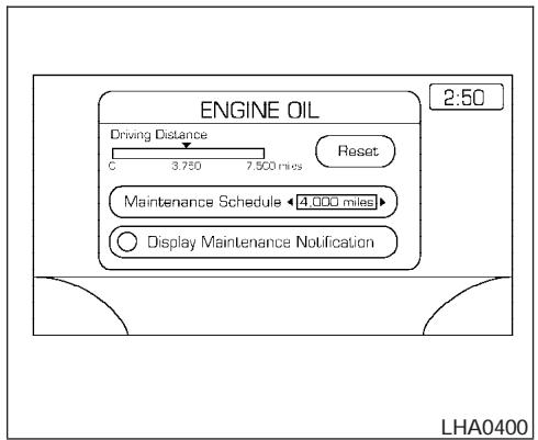
To set the maintenance interval, select the "Maintenance Schedule" key by using the joystick and push the joystick to right or left.
To reset the maintenance interval, select the "Reset" key using the joystick and push the "ENTER" button.
To display the MAINTENANCE INFORMATION automatically when set trip distance is reached, select the “Display Maintenance Notification” key and push the “ENTER” button.
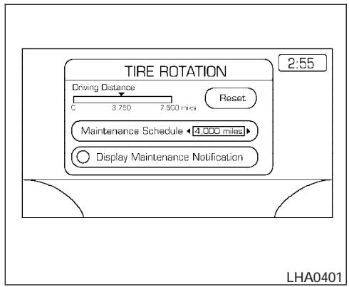
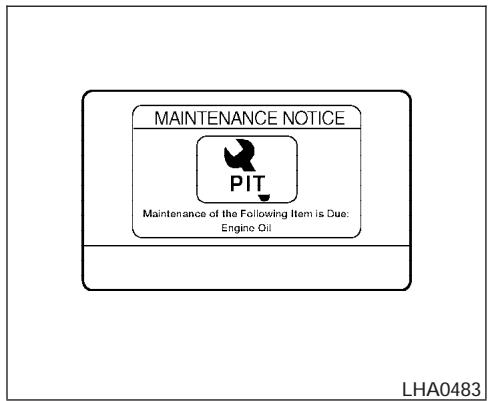
The “MAINTENANCE NOTICE” screen (“ENGINE OIL” and “TIRE ROTATION”) will be automatically displayed as shown when both of the following conditions are met:
- the vehicle is driven the set distance and the ignition key is turned OFF.
- the ignition key is turned ON the next time the vehicle will be driving.
To return to the previous display after the “MAIN-TENANCE NOTICE” screen is displayed, press the PREV button.
The “MAINTENANCE NOTICE” screen displays each time the key is turned ON until one of the following conditions are met:
- "RESET" is selected.
- "Display Maintenance and Notification" is set OFF.
● the maintenance interval is set again.
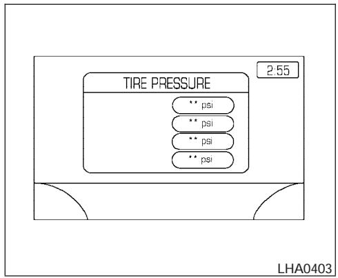
Tire pressure information
To view "TIRE PRESSURE" information, push the "TRIP" button repeatedly until the "MAINTENANCE" screen is displayed. Select "TIRE PRESSURE" using the joystick and push the "ENTER" button.
Pressure indication in * * psi on the screen indicates that the pressure is being measured. After a few driving trips, the pressure for each tire will be displayed randomly.
The order of tire pressure figures displayed on the screen does not correspond with the actual order of the tire position.
Tire pressure rises and falls depending on the heat caused by the vehicle's operation and the outside temperature.
In case of low tire pressure, a message is displayed on the screen:
FLAT TIRE — low tire air pressure.

WARNING
When a spare tire is mounted or a wheel is replaced, tire pressure will not be indicated and the low tire pressure warning system will not function. Contact your NISSAN dealer as soon as possible for tire replacement and/or system resetting.
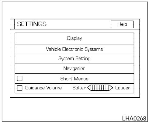
HOW TO USE THE "SETTING" BUTTON
To adjust the various settings within the display screen press the "SETTING" button.
After pressing the SETTING button a menu will be shown on the display screen which will allow you to program several functions such as the display screen appearance, programmable features for your vehicles electronics system and other system settings such as your clock. To make a selection from this mode use the joystick and press the "ENTER" button.
SETTING THE DISPLAY (Audio or HVAC display):
The audio or HVAC reading can be displayed at the bottom of the screen. Choose the "Audio" or "HVAC" (Heater and air conditioner) key to be displayed at the bottom, by using the joystick and pressing the ENTER button to select or deselect the key. The setting condition will normally appear on the screen. To return to the setting screen, push the "SETTING" button or "PREV" button.
Display settings
The DISPLAY SETTINGS screen will appear after pushing the "SETTING" button, selecting "Display" key and pushing the "ENTER" button.
Brightness/Contrast/Map Background:
To adjust the brightness and contrast of the screen, select the "Brightness/contrast" key and push the "ENTER" button. You can then use the joystick to adjust the brightness to Darker or Brighter and the contrast to Lower or Higher. For information on Map Background, please refer to the separate Navigation System Owner's Manual.
Display Off:
To turn off the screen, push the "SETTING" button and select the "Display" key and "Display Off" key. The indicator of the "Display Off" will turn to amber. When any mode button is pushed with the screen off, the screen turns on for further operation. The screen will turn off automatically 5 seconds after the operation is finished on the map display in the Audio, HVAC (Heater and air conditioner), SETTING or VEHICLE INFO modes.
To turn on the screen, push the “SETTING” button and select the “Display” key and “Display Off” key, then set the screen to on by pushing the “ENTER” button.
Setting Audio or HVAC display:
Choose the "Audio" or "HVAC" (Heater and air conditioner) key to be displayed at the bottom, by using the joystick. The audio or HVAC setting condition will normally appear on the screen. To return to the setting screen, push the "SETTING" button or "PREV" button.
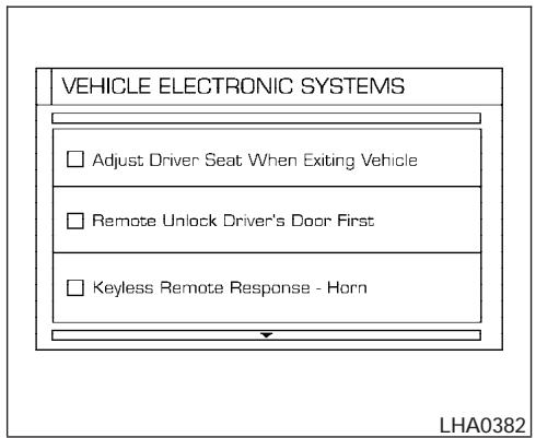
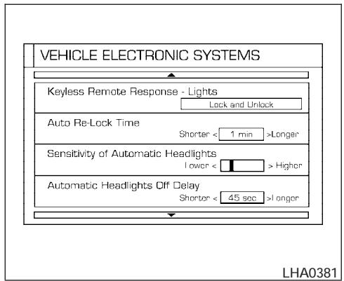
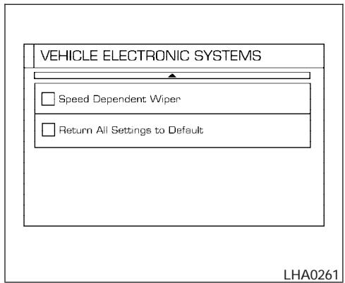
Vehicle electronic systems
The VEHICLE ELECTRONIC SYSTEMS screen will appear when selecting the “Vehicle Electronic Systems” key with the joystick and pushing the “ENTER” button.
To set the various electronic systems operating conditions, select the applicable item using the joystick, and push the “ENTER” button. The indicator light, box at left of selected item, alternately turns on and off each time the “ENTER” button is pressed.
Indicator light is illuminated — ON
Indicator light is not illuminated — OFF
Adjust driver seat when exiting vehicle:
With this option ON, the driver's seat automatically moves back and returns to the original position for ease of exit and entry.
Remote unlock driver's door first:
This option allows you to select which doors will unlock first during an unlocking operation:
Only the driver's door All the doors
Keyless remote response — horn:
This key allows you to change the horn chirp mode that occurs when pressing the LOCK or UNLOCK button on the keyfob.
NOTE:
If you change the horn beep or the lamp flash feature with the keyfob, the display screen will not show the current mode. Use the keyfob to return to the previous mode and re-enable the display screen control.
Keyless remote response — lights:
This key allows you to change the hazard indicator flash mode that occurs when pressing the LOCK or UNLOCK button on the keyfob.
NOTE:
If you change the horn beep or the lamp flash feature with the keyfob, the mode will not be changed with the display. Use the keyfob to return to the previous mode and re-enable the display control.
Auto re-lock time:
This key allows you to set the length of time before doors auto re-lock.
Sensitivity of automatic headlights:
This key allows you to set the sensitivity of the automatic headlights:
- Lower- less sensitive, automatic headlights will take longer to come on when the head-light sensor senses less ambient light.
- Higher- more sensitive, automatic headlights will come on quicker when the headlight sensor senses less ambient light.
Automatic headlights off delay:
This key allows you to set the length of time before the automatic headlights turn off after exiting the vehicle.
Speed dependent wiper:
This key allows you to turn on or turn off the driving speed dependent intermittent wiper function.
Return all settings to default:
When this key is selected and turned on using the "ENTER" button, all settings made by VEHICLE ELECTRONICS will return to the default settings.
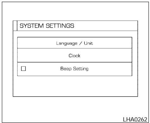
System settings
Language/Unit
The LANGUAGE/UNIT screen will appear when selecting the “Language/Unit” key and pushing the “ENTER” button.
Language: English or French
Unit: US — mile, °F, MPG
Metric — km, °C, L/100 km
You can select the language and unit using the joystick and "ENTER" button.
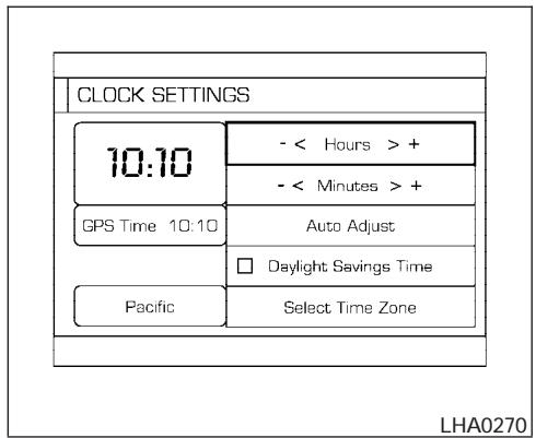
Clock
Adjusting the time:
Select the “Hours” or “Minutes” key and move the joystick to the right or left to adjust the time.
The time will change step by step.
After completion of the setting, press the "PREV" button.
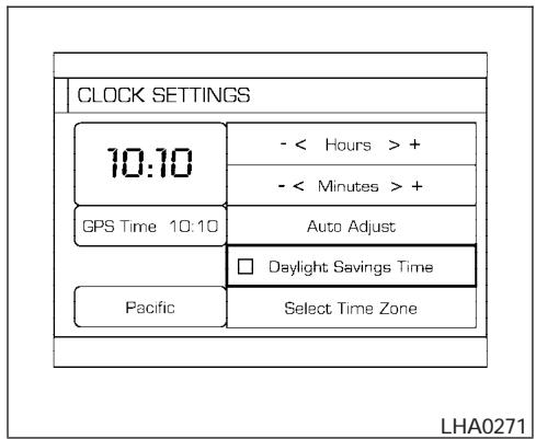
Setting daylight savings time:
Use the “Daylight Saving Time” key to adjust the clock to daylight savings time.
ON: The displayed time advances by 1 hour.
OFF: The current time is displayed.
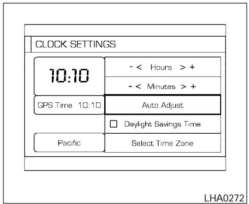
Adjusting the time to the GPS:
Select the "Auto Adjust" key.
The time will be reset to the GPS time.
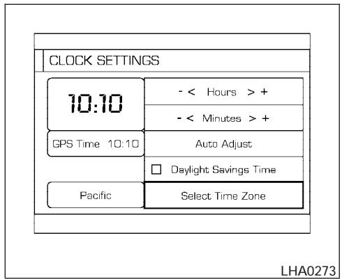
Selecting the time zone:
- Select the "Select Time Zone" key.
The [TIME ZONE] screen will appear.
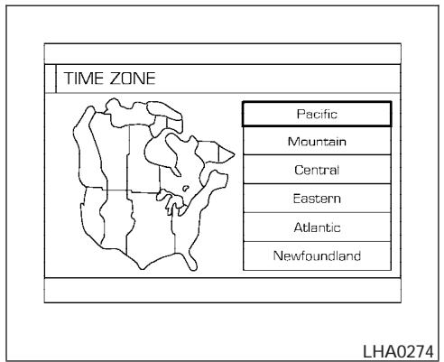
-
Select one of the following zones depending on the current location.
-
Pacific zone
- Mountain zone
- Central zone
- Eastern zone
- Atlantic zone
- Newfoundland zone
After selection, the [CLOCK SETTINGS] screen will appear.
REARVIEW MONITOR (if so equipped)
The GPS time (manual time) corresponding to the selected zone will be displayed. Pacific zone has been set as the initial (default) setting.
Beep setting
With this option ON, a beep will sound if any audio button is pushed.

BUTTON
To change the display brightness, push the ⚙/ Dog button. Pushing the button again will change the display to DAY or NIGHT display. Then, adjust the brightness moving the joystick right or left.
If no operation is done within 10 seconds, or if the "PREV" button is pushed, the display will return to the previous display.
When the selector lever is shifted into the R (Reverse) position, the monitor display shows view to the rear of the vehicle.

WARNING
- The system is designed as an aid to the driver in detecting large stationary objects to help avoid damaging the vehicle. The system will not detect small objects below the bumper, and may not detect objects close to the bumper or on the ground.
- The rear view camera is a convenience but it is not a substitute for proper backing. Always turn and check that it is safe to do so before backing up. Always back up slowly.
- Objects viewed in the rear view monitor differ from actual distance because a wide-angle lens is used. Objects in the rear view monitor will appear visually opposite than when viewed in the rear view and outside mirrors.
- Make sure that the back door is securely closed when backing up.
-
Do not put anything on the rear view camera. The rear view camera is installed beside the license plate light.
-
When washing the vehicle with high-pressure water, be sure not to spray it around the camera. Otherwise, water may enter the camera unit causing water condensation on the lens, a malfunction, fire or an electric shock.
- Do not strike the camera. It is a precision instrument. Otherwise, it may malfunction or cause damage resulting in a fire or an electric shock.

CAUTION
There is a plastic cover over the camera. Do not scratch the cover when cleaning dirt or snow from the cover.
HOW TO READ THE DISPLAYED LINES
Lines which indicate the vehicle clearance and distances to objects with reference to the bumper line Ⓐ are displayed on the monitor.

flowchart
graph TD
    1["Step 1"] --> 2["Step 2"]
    2 --> 3["Step 3"]
    3 --> 4["Step 4"]
    4 --> A["End Point"]
    style 1 fill:#f9f,stroke:#333
    style 2 fill:#f9f,stroke:#333
    style 3 fill:#f9f,stroke:#333
    style 4 fill:#f9f,stroke:#333
    style A fill:#ccf,stroke:#333
They are indicated as reference distances to objects. The lines and colors in the display indicate distances from the back bumper line(A) in the illustration.
① 1.5 feet (0.5 m) red
② 3 feet (1 m) yellow
③ 7 feet (2 m) green
④ 10 feet (3 m) green
The vehicle clearance lines are wider than the actual clearance.
To adjust the quality of the screen, refer to HOW TO USE THE "SETTING" BUTTON in this section.
- When it is difficult to see in the rearward direction due to shady conditions, press the "ENTER" button to make objects in the monitor brighter.
- To change the brightness, press the "ENTER" button again, turn the key switch OFF or shift to reverse and wait for 10 seconds.
OPERATING TIPS
- When the selector lever is shifted to R, the monitor screen automatically changes to the rear view monitor mode. However, the radio can be heard.
-
It may take some time until the rear view monitor is displayed after the selector lever has been shifted to R. Objects may be distorted momentarily until the rear view monitor screen is displayed completely. When the selector lever is returned to a position other than R, it may take some time until the screen changes. Objects on the screen may be distorted until they are completely displayed.
-
When the temperature is extremely high or low, the screen may not clearly display objects. This is not a malfunction.
- When strong light directly enters the camera, objects may not be displayed clearly.
- Vertical lines may be seen in objects on the screen. This is due to strong reflected light from the bumper. This is not a malfunction.
- The screen may flicker under fluorescent light. This is not a malfunction.
- The colors of objects on the rear view monitor may differ somewhat from those of the actual object.
- When the contrast of objects is low at night, pushing the “ENTER” button may not change the brightness.
- Objects on the monitor may not be clear in a dark place or at night.
- If dirt, rain or snow attaches to the camera, the rear view monitor may not display objects. Clean the camera.
- Do not use alcohol, benzine or thinner to clean the camera. This will cause discoloration. To clean the camera, wipe with a cloth dampened with a diluted mild cleaning agent and then wipe with a dry cloth.
VENTILATORS
- Do not damage the camera as the monitor screen may be adversely affected.
- Do not use body wax on the camera window. Wipe off the wax with a clean cloth dampened with mild detergent diluted with water.
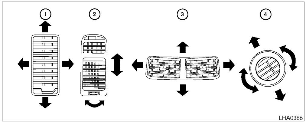
flowchart
graph LR
    A["1: Vehicle Position"] --> B["2: Car Window"]
    B --> C["3: Air Condition Panel"]
    C --> D["4: Fan Rotation System"]
    D --> A
Adjust air flow direction for the driver and passenger side ①, center ②, and rear passenger ③ and ④ ventilators by moving the ventilator slide and/or ventilator assemblies.
HEATER AND AIR CONDITIONER (manual)

WARNING
- The air conditioner cooling function operates only when the engine is running.
- Do not leave children or adults who would normally require the assistance of others alone in your vehicle. Pets should also not be left alone. They could accidentally injure themselves or others through inadvertent operation of the vehicle. Also, on hot, sunny days, temperatures in a closed vehicle could quickly become high enough to cause severe or possibly fatal injuries to people or animals.
- Do not use the recirculation mode for long periods as it may cause the interior air to become stale and the windows to fog up.
- Positioning of the heater and/or air conditioner controls should not be done while driving so full attention may be given to vehicle operation.
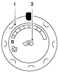
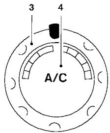
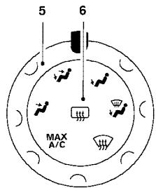
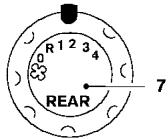
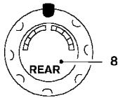
WHA0501
- Fan speed control dial
- Air recirculation button
- Temperature control dial
- Air conditioner button
- Air flow control dial
- Rear window defroster switch
- Rear fan speed dial
- Rear temperature dial
CONTROLS
Fan control dial
The fan control dial turns the fan on and off, and controls fan speed.
Air flow control dial
The air flow control dial allows you to select the air flow outlets.
MAX — Air flows from center and side A/C vents with maximum cooling (air conditioning).

— Air flows from center and side ventilators.

— Air flows from center and side ventilators and the front and rear floor outlets.

— Air flows mainly from the front and rear floor outlets.

— Air flows from defroster outlets and the front and rear floor outlets.

— Air flows mainly from defroster outlets.
The air flow control dial also has intermediate positions which allow the air flow to be distributed between 2 of the icon positions on the air flow control dial.
Temperature control dial
The temperature control dial allows you to adjust the temperature of the outlet air. To lower the temperature, turn the dial to the left. To increase the temperature, turn the dial to the right.

Air recirculation button
ON position:
Push the 📄 button to recirculate air inside the vehicle.
Push the 📄 button to the on position when:
● driving on a dusty road.
- to prevent traffic fumes from entering passenger compartment.
- for maximum cooling when using the air conditioner.
OFF position:
Push the 📄 button again to turn air recirculation off. Outside air is drawn into the passenger compartment and distributed through the selected outlet.
Use the off position for normal heater or air conditioner operation.
A/C
Air conditioner button
Start the engine, turn the fan control dial to the desired position and push the /CC button to turn on the air conditioner. A/C will appear on the display when the air conditioner is operating. To turn off the air conditioner, push the /CC button again, the display will show A/C OFF.
The air conditioner cooling function operates only when the engine is running.
Rear window defroster switch
For more information about the rear window defroster switch, see “Rear window defroster switch” in the “Instruments and controls” section of this manual.
HEATER OPERATION
Heating
This mode is used to direct heated air to the foot outlets. Some air also flows from the defrost outlets.
- Push the 📄 button to the OFF position for normal heating. The indicator light on the 📄 button will go off. ( ✉ will appear on the display, if so equipped.)
- Turn the air flow control dial to the position.
- Turn the fan control dial to the desired position.
- Turn the temperature control dial to the desired position between the middle and the hot position.
Ventilation
This mode directs outside air to the side and center ventilators.
- Push the 📄 button to the OFF position. The indicator light on the 📄 button will go off. ( ⏰ will appear on the display, if so equipped.)
-
Turn the air flow control dial to the position.
-
Turn the fan control dial to the desired position.
- Turn the temperature control dial to the desired position.
Defrosting or defogging
This mode directs the air to the defrost outlets to defrost/defog the windows.
- Turn the air flow control dial to the position.
- Turn the fan control dial to the desired position.
- Turn the temperature control dial to the desired position between the middle and the hot position.
- To quickly remove ice or fog from the windows, turn the fan control dial to 4 and the temperature control lever to the full HOT position.
- When the ⏻ position is selected, the air conditioner automatically turns on (however, the indicator light on the A/C button will not come on and A/C will not appear on the display, if so equipped) if the outside temperature is more than 36°F (2°C). If in defrost mode for more than one minute, the air conditioning system will continue to operate until the fan control dial is turned to OFF or
the vehicle is shut off, even if the air flow control dial is turned to a position other than the ⏻ position. This dehumidifies the air which helps defog the windshield. The ⏻ mode automatically turns off, allowing outside air to be drawn into the passenger compartment to further improve the defogging performance.
Bi-level heating
The bi-level mode directs warmed air to the side and center vents and to the front and rear floor outlets.
- Push the 📄 button to the OFF position. The indicator light on the 📄 button will go off. ( ✉ will appear on the display, if so equipped.)
- Turn the air flow control dial to the position.
- Turn the fan control dial to the desired position.
- Turn the temperature control dial to the desired position.
Heating and defogging
This mode heats the interior and defogs the wind-shield.
- Turn the air flow control dial to the position.

- Turn the fan control dial to the desired position.
- Turn the temperature control dial to the desired position between the middle and the hot position.
- When the ⚫ position is selected, the air conditioner automatically turns on (however, the indicator light on the A/C button will not come on and A/C will not appear on the display, if so equipped) if the outside temperature is more than 36°F (2°C). If in defrost mode for more than one minute, the air conditioning system will continue to operate until the fan control dial is turned to OFF or the vehicle is shut off, even if the air flow control dial is turned to a position other than the ⚫ position. This dehumidifies the air which helps defog the windshield. The ⚫ mode automatically turns off, allowing outside air to be drawn into the passenger compartment to further improve the defogging performance.
Operating tips
Clear snow and ice from the wiper blades and air inlet in front of the windshield. This improves heater operation.
AIR CONDITIONER OPERATION
Start the engine, turn the fan control dial to the desired position, and push in the A/C button to activate the air conditioner. When the air conditioner is on, cooling and dehumidifying functions are added to the heater operation.
The air conditioner cooling function operates only when the engine is running.
Cooling
This mode is used to cool and dehumidify the air.
- Push the 📄 button to the OFF position.
- Turn the air flow control dial to the position.
- Turn the fan control dial to the desired position.
- Push the A/C button. The indicator light on the A/C button will come on. (A/C will appear on the display, if so equipped.)
- Turn the temperature control dial to the desired position.
- For quick cooling when the outside temperature is high, push the 📄 button to the ON position. The indicator light on the 📄 button will come on. ( 📄 will appear on the display, if so equipped.) Be
sure to return the 📄 to the OFF position for normal cooling. The indicator light on the 🔊 button will go off. ( 🔊 will appear on the display, if so equipped.) You may also select MAX A/C for quick cooling.
Dehumidified heating
This mode is used to heat and dehumidify the air.
- Push the 📄 button to the OFF position. The indicator light on the 📄 button will go off. ( ✉ will appear on the display, if so equipped.)
- Turn the air flow control dial to the position.
- Turn the fan control dial to the desired position.
- Push the A/C button on. The indicator light on the A/C button will come on. (A/C will appear on the display, if so equipped.) The air conditioning system will continue to operate until the fan control dial is turned to OFF or the vehicle is shut off, even if the air flow control dial is turned to a position other than the ⚪ position.
- Turn the temperature control dial to the desired position.
Operating tips
- Keep the windows closed while the air conditioner is in operation.
- After parking in the sun, drive for 2 or 3 minutes with the windows open to vent hot air from the passenger compartment. Then, close the windows. This allows the air conditioner to cool the interior more quickly.
- The air conditioning system should be operated for approximately 10 minutes at least once a month. This helps prevent damage to the system due to lack of lubrication.
- If the engine coolant temperature gauge indicates engine coolant temperature over the normal range, turn the air conditioner off. See "If your vehicle overheats" in the "In case of emergency" section of this manual.
AIR FLOW CHARTS
The following charts show the button and dial positions for MAXIMUM AND QUICK heating, cooling or defrosting. For additional information on heating and cooling see "Heater and air conditioner" in this section. The air recirculation ( ) button should always be in the OFF position for heating and defrosting.
DEFROSTING/DEFOGGING
←: Air passed through heater core
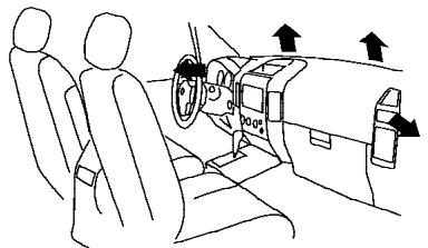
natural_image
Line drawing of a car interior showing two people seated, with directional arrows indicating movement or force (no text or symbols)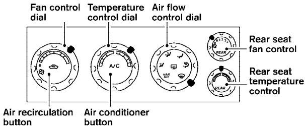
| A/C Button | Rear seat A/C fan control | Air flow control | Temp control | Fan control | Air recirculation button |
| OFF | OFF | HOT (RIGHT) | HI (RIGHT) | OFF |
WHA0512
BI-LEVEL
HEATING

: Air passed through heater core
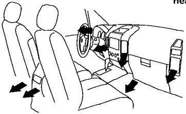
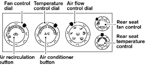
| A/C Button | Rear seat fan control | Air flow control | Temp control | Fan control | Air recirculation button | Rear seat temp control |
| OFF | ON (R,1,2,3,4) | HOT (RIGHT) | HI (RIGHT) | OFF | HOT |
WHA0514
HEATING

: Air passed through heater core
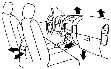
natural_image
Line drawing of a car interior showing three seats and directional arrows indicating movement (no text or symbols)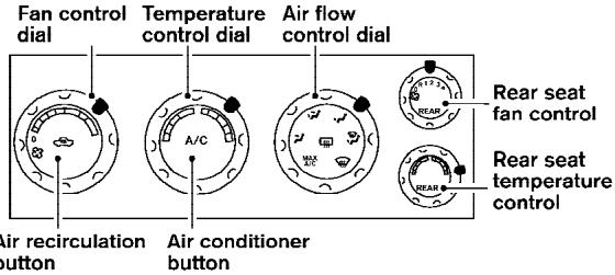
| A/C Button | Rear seat fan control | Air flow control | Temp control | Fan control | Air recirculation button | Rear seat temp control |
| OFF | ON (R,1,2,3,4) | HOT (RIGHT) | HI (RIGHT) | OFF | HOT |
WHA0513
HEATING &
DEFROSTING/
DEFOGGING

: Air passed through heater core
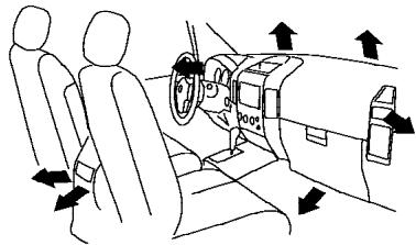
natural_image
Diagram of a car interior showing two people seated, with directional arrows indicating airflow or movement (no text or symbols present)Fan control dial
Temperature control dial
Air flow control dial
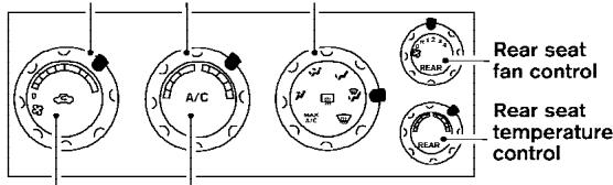
Air recirculation button
Air conditioner button
| A/C Button | Rear seat fan control | Air flow control | Temp control | Fan control | Air recirculation button | Rear seat temp control |
| OFF | ON (R,1,2,3,4) | HOT (RIGHT) | HI (RIGHT) | OFF | HOT |
WHA0518
COOLING

: Air not passed through heater core
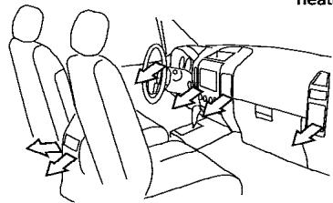
natural_image
Line drawing of a car interior showing two seats and a steering wheel (no text or symbols)Fan control dial
Temperature control dial
Air flow control dial
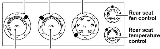
Air recirculation button
Air conditioner button
| A/C Button | Rear seat fan control | Air flow control | Temp control | Fan control | Air recirculation button | Rear seat temp control |
| Auto turns ON | ON (R,1,2,3,4) | MAX A/C | COOL (LEFT) | HI (RIGHT) | ON | COOL |
WHA0515
COOLING

Air not passed through heater core
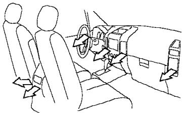
natural_image
Line drawing of a car interior showing three seats and a steering wheel (no text or symbols)Fan control dial
Temperature control dial
Air flow control dial
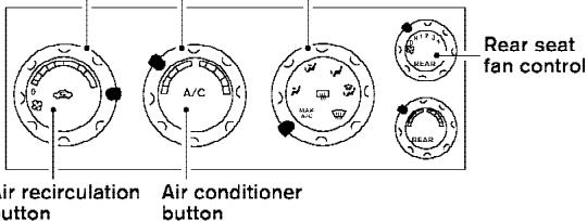
| A/C Button | Rear seat fan control | Air flow control | Temp control | Fan control | Air recirculation button |
| Automatically turns on | ON (R) | MAX A/C | COOL (LEFT) | HI (RIGHT) | ON |
REAR SEAT A/C FAN CONTROLS

Air not passed through heater core
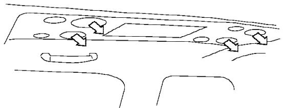
natural_image
Simple line drawing of a vehicle dashboard with no text or symbolsRear seat passenger A/C fan control dial
Rear seat passenger temperature control dial
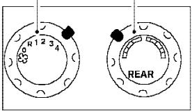
| Fan control | Temperature control |
| 4 | COOL (LEFT) |
WHA0516
HEATING
←: Air passed through heater core
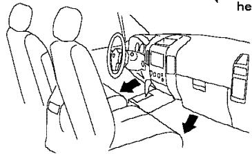
natural_image
Line drawing of a car interior showing two people seated, with dashboard and steering wheel (no text or symbols)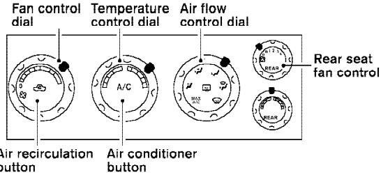
| A/C Button | Rear seat fan control | Air flow control | Temp control | Fan control | Air recirculation button |
| OFF | ON (R) | HOT (RIGHT) | HI (RIGHT) | OFF |
REAR SEAT A/C
FAN CONTROLS
←: Air passed through heater core
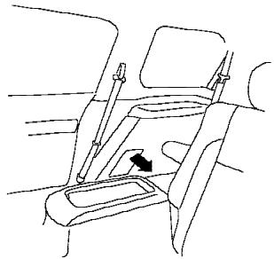
natural_image
Line drawing of a car seatbelt with a hand valve and arrow indicating direction (no text or symbols)Rear seat passenger A/C fan control dial
Rear seat passenger temperature control dial
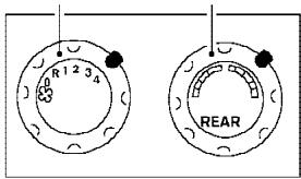
| Fan control | Temperature control |
| 4 | HOT (RIGHT) |
WHA0517
HEATER AND AIR CONDITIONER
(automatic) (if so equipped)
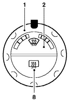
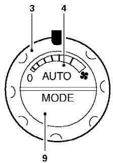
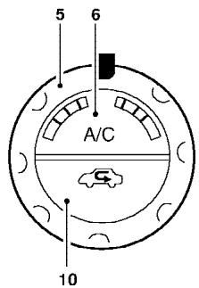
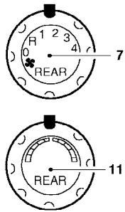
LHA0491
- Driver temperature control dial
- Front window defroster button
- Fan speed control and system OFF dial
- AUTO button
- Passenger temperature control dial
- A/C ON/OFF button
- Rear control and fan speed dial
- Rear window defroster button
- MODE button
- Air recirculation button
- Rear temperature control dial
WARNING
- The air conditioner cooling function operates only when the engine is running.
-
Do not leave children or adults who would normally require the assistance of others alone in your vehicle. Pets should also not be left alone. They could accidentally injure themselves or others through inadvertent operation of the vehicle. Also, on hot, sunny days, temperatures in a closed vehicle could quickly become high enough to cause severe or possibly fatal injuries to people or animals.
-
Do not use the recirculation mode for long periods as it may cause the interior air to become stale and the windows to fog up.
- Positioning of the heater and/or air conditioner controls should not be done while driving so full attention may be given to vehicle operation.
Start the engine and operate the controls to activate the air conditioner.
AUTOMATIC OPERATION
Cooling or heating (auto)
This mode may be normally used all year round as the system automatically works to keep a constant temperature. Air flow distribution and fan speed are also controlled automatically.
- Push the AUTO button on. (AUTO will be displayed.)
- Turn the temperature dial to the left or right to set the desired temperature. Driver and passenger temperatures can be set independently.
- Adjust the temperature dial to about 75irc F ( 24irc C) for normal operation.
- The temperature of the passenger compartment will be maintained automatically. Air flow distribution, fan speed and A/C on/off are also controlled automatically.
Dehumidified defrosting or defogging
- Turn the defroster control dial 📋 to the left. The display will show the defrost icon.
- Turn the temperature dial to the left or right to set the desired temperature.
- To quickly remove ice from the outside of the windows, push the manual fan control button ⚙️ and set to the maximum position.
- As soon as possible after the windshield is clean, push the AUTO button to return to the auto mode.
- When the DEF control is activated, the air conditioner will automatically be turned on at outside temperatures above 36°F (2°C). If in defrost mode for more than one minute, the air conditioning system will continue to operate until the fan control is turned OFF or the vehicle is shut off, even if the air flow mode control button is used to select a position other than the position. This dehumidifies the air which helps defog the windshield. The air recirculate mode automatically turns off, allowing out-
side air to be drawn into the passenger compartment to further improve the defogging performance.
MANUAL OPERATION
Fan speed control
Push the fan control button 🎨 up or down to manually control the fan speed.
Push the AUTO button to return to automatic control of the fan speed.
Air recirculation
The ⬇ mode automatically turns off, allowing outside air to be drawn into the passenger compartment to prevent fogging.
Push the air recirculation button ⬆ to recirculate interior air inside the vehicle. Push the AUTO button to return to automatic mode.
The air recirculation button will not be activated when the air conditioner is in DEF, floor, or floor/defrost mode.
Air flow control
Pushing the MODE button manually controls air flow and selects the air outlet to:

— Air flows from center and side ventilators.

— Air flows from center and side ventilators and foot outlets.

— Air flows mainly from foot outlets.

— Air flows from defroster and foot outlets.

— Air flows mainly from defroster outlets.
To turn system off
Push and hold the fan down button until the system turns off.
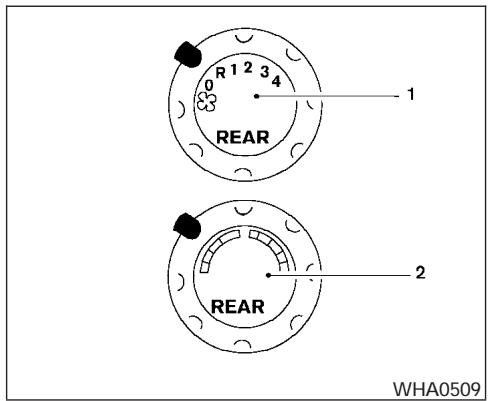
- Rear fan speed control dial.
- Rear temperature control dial.
REAR CONTROL BUTTON
You can adjust the climate control system for rear seat passengers using the buttons on the main control panel. Front passengers can control the rear functions by placing the controls on any setting other than the "R".
OPERATING TIPS
- When the engine coolant temperature and outside air temperature are low, the air flow from the foot outlets may not operate for a maximum of 150 seconds. However, this is not a malfunction. After the coolant temperature warms up, air flow from the foot outlets will operate normally.
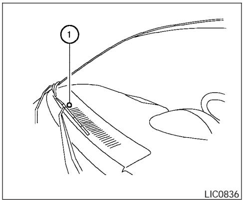
The sunload sensor ①, located on the top center of the instrument panel, helps the system maintain a constant temperature. Do not put anything on or around this sensor.
REAR SEAT AIR CONDITIONER
To operate the rear air conditioner, the engine must be running.
The rear seat air conditioner can be turned on and off from the front controls. If the rear seat fan control dial is set to (0), the air conditioner is turned off. If it is set to any of the fan speed positions, air is discharged from the rear vents at the corresponding speed. When the rear seat fan control dial is set to (R), the rear seat passengers control their own fan speed.
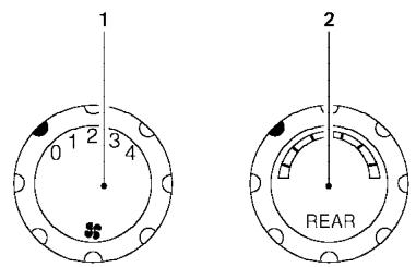
LHA0490
- Rear fan speed control dial.
- Rear temperature control dial.
CONTROLS
Fan control dial
The fan control dial turns the rear vent fan on and off, and controls fan speed.
Temperature control dial
The temperature control dial allows rear passengers to adjust the temperature of the outlet air.
SERVICING AIR CONDITIONER
The air conditioner system in your NISSAN vehicle is charged with a refrigerant designed with the environment in mind.
This refrigerant does not harm the earth's ozone layer.
Special charging equipment and lubricant is required when servicing your NISSAN air conditioner. Using improper refrigerants or lubricants will cause severe damage to your air conditioner system. See “Air conditioner system refrigerant and lubricant recommendations” in the “Technical and consumer information” section of this manual.
A NISSAN dealer is able to service your “environmentally friendly” air conditioning system.

WARNING
The air conditioner system contains refrigerant under high pressure. To avoid personal injury, any air conditioner service should be done only by an experienced technician with proper equipment.
AUDIO SYSTEM
RADIO
Turn the ignition key to the ACC or ON position and press the PWR (power)/VOL (volume) knob to turn the radio on. If you listen to the radio with the engine not running, the key should be turned to the ACC position.
Radio reception is affected by station signal strength, distance from radio transmitter, buildings, bridges, mountains and other external influences. Intermittent changes in reception quality normally are caused by these external influences.
Using a cellular phone in or near the vehicle may influence radio reception quality.
Radio reception
Your NISSAN radio system is equipped with state-of-the-art electronic circuits to enhance radio reception. These circuits are designed to extend reception range, and to enhance the quality of that reception.
However there are some general characteristics of both FM and AM radio signals that can affect radio reception quality in a moving vehicle, even when the finest equipment is used. These characteristics are completely normal in a given reception area, and do not indicate any malfunction in your NISSAN radio system.
Reception conditions will constantly change because of vehicle movement. Buildings, terrain, signal distance and interference from other vehicles can work against ideal reception. Described below are some of the factors that can affect your radio reception.
FM RADIO RECEPTION
Range: FM range is normally limited to 25 – 30 miles (40 – 48 km), with monaural (single channel) FM having slightly more range than stereo FM. External influences may sometimes interfere with FM station reception even if the FM station is within 25 miles (40 km). The strength of the FM signal is directly related to the distance between the transmitter and receiver. FM signals follow a line-of-sight path, exhibiting many of the same characteristics as light. For example they will reflect off objects.
Fade and drift: As your vehicle moves away from a station transmitter, the signals will tend to fade and/or drift.
Static and flutter: During signal interference from buildings, large hills or due to antenna position (usually in conjunction with increased distance from the station transmitter) static or flutter can be heard. This can be reduced by adjusting the treble control to reduce treble response.
Multipath reception: Because of the reflective characteristics of FM signals, direct and reflected signals reach the receiver at the same time. The signals may cancel each other, resulting in momentary flutter or loss of sound.
AM RADIO RECEPTION
AM signals, because of their low frequency, can bend around objects and skip along the ground. In addition, the signals can be bounced off the ionosphere and bent back to earth. Because of these characteristics, AM signals are also subject to interference as they travel from transmitter to receiver.
Fading: Occurs while the vehicle is passing through freeway underpasses or in areas with many tall buildings. It can also occur for several seconds during ionospheric turbulence even in areas where no obstacles exist.
Static: Caused by thunderstorms, electrical power lines, electric signs and even traffic lights.
SATELLITE RADIO RECEPTION (if so equipped)
When the satellite radio is first installed or the battery has been replaced, the satellite radio may not work properly. This is not a malfunction. Wait more than 10 minutes with satellite radio ON and
the vehicle outside of any metal or large building for satellite radio to receive all of the necessary data.
No satellite radio reception is available and "NO SAT" is displayed when the SAT band option is selected unless optional satellite receiver and antenna are installed and an XM® or SIRIUS™ satellite radio service subscription is active.
Satellite radio performance may be affected if cargo carried on the roof blocks the satellite radio signal.
If possible, do not put cargo over the satellite antenna.
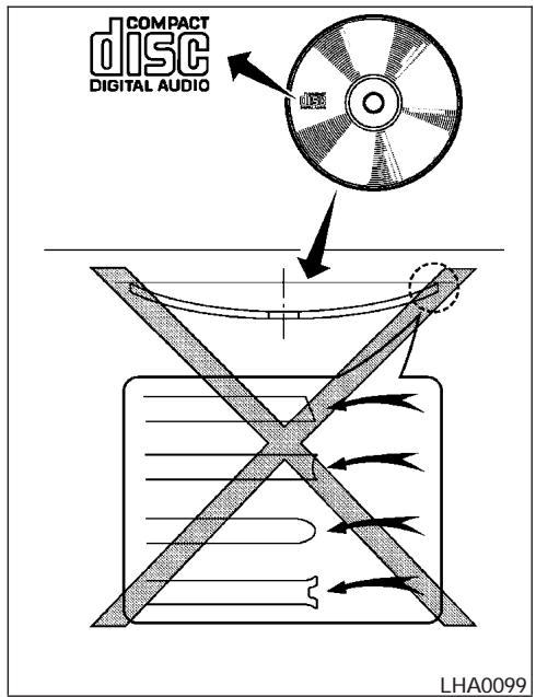
AUDIO OPERATION PRECAUTIONS
Compact disc (CD) player
- Only use high quality 4.7 inches (12 cm) round discs that have the “COMPACT disc DIGITAL AUDIO” logo on the disc or packaging.
- During cold weather or rainy days, the player may malfunction due to the humidity. If this occurs, remove the CD and dehumidify or ventilate the player completely.
- The player may skip while driving on rough roads.
- The CD player sometimes cannot function when the compartment temperature is extremely high. Decrease the temperature before use.
- Do not expose the CD to direct sunlight.
-
CDs that are in poor condition or are dirty, scratched or covered with fingerprints may not work properly.
● The following CDs may not work properly: -
Copy control compact discs (CCCD)
- Recordable compact discs (CD-R)
- Rewritable compact discs (CD-RW)
- Do not use the following CDs as they may cause the CD player to malfunction:
• 3.1 in (8 cm) discs with an adapter
• CDs that are not round
• CDs with a paper label
- CDs that are warped, scratched, or have abnormal edges
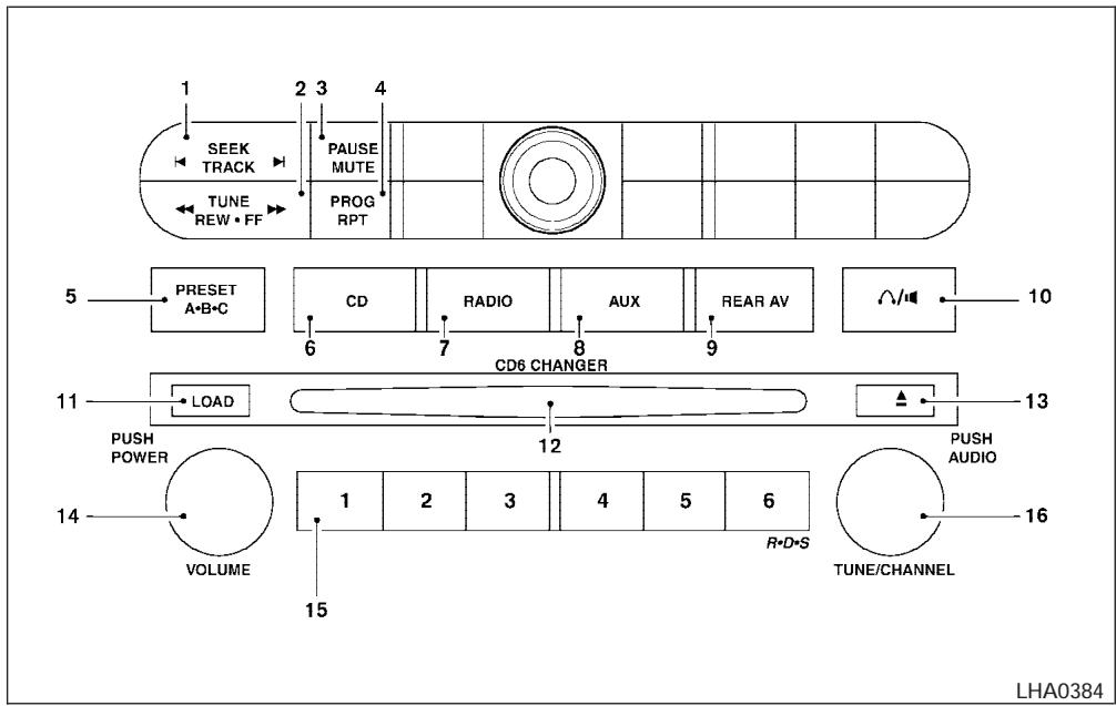
Type A
- SEEK/TRACK change button
- TUNE/REW/FF button
- PAUSE/MUTE button
- PROG/RPT button
-
PRESET A-B-C select button
-
CD play button
- RADIO button
- AUX button
- REAR AV button
-
speaker control button
-
LOAD button
- CD insert slot
- CD eject button
- POWER/VOLUME control knob
- Station and CD select buttons (1 - 6)
- Tuning and AUDIO control knob (BASS, MID, TREBLE, FADE and BALANCE)
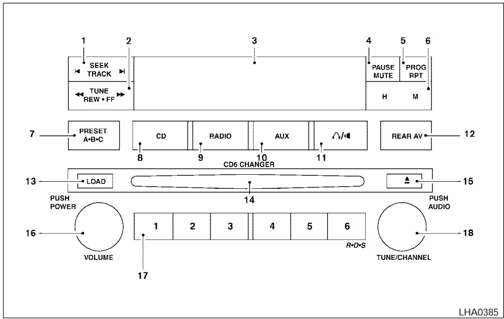
Type B
- SEEK/TRACK change button
- TUNE/REW/FF button
- Display
- PAUSE/MUTE button
-
PROG/RPT button
-
H/M button (clock set buttons)
- PRESET A-B-C select button
- CD play button
- RADIO button
-
AUX button
-
speaker control button
- REAR AV button
- LOAD button
- CD insert slot
- CD eject button
- POWER/VOLUME control knob
- Station and CD select buttons (1 - 6)
- Tuning and AUDIO control knob (BASS, MID, TREBLE, FADE and BALANCE)
FM-AM-SAT RADIO WITH COMPACT DISC CHANGER (Type A and B) (if so equipped)
No satellite radio reception is available and “NO SAT” is displayed when the RADIO button is pressed to access satellite radio stations unless optional satellite receiver and antenna are installed (retrofit unavailable without factory satellite radio pre-wiring), and an XM ® or SIRIUS ™ satellite radio service subscription is active.
Audio main operation
POWER/VOLUME control:
Turn the ignition key to ACC or ON, and then push the POWER/VOLUME control knob while
the system is off to call up the mode (radio or CD) which was playing immediately before the system was turned off.
To turn the system off, press the POWER/VOLUME control knob.
Turn the POWER/VOLUME control knob to adjust the volume.
This vehicle has speed sensitive control volume (SSV) for audio. The audio volume changes as the driving speed changes.
AUDIO knob (BASS, MIDRANGE, TREBLE, FADE, BALANCE and SSV if so equipped):
Press the AUDIO knob to change the mode as follows:
BASS → MID → TREBLE → FADE → BALANCE → SSV (if so equipped)
To adjust Bass, Mid (Midrange), Treble, Fade and Balance, press the AUDIO knob until the desired mode appears in the display. Turn the Tuning knob to adjust Bass and Treble to the desired level. You can also use the Tuning knob to adjust Fader and Balance modes. Fader adjusts the sound level between the front and rear speakers and Balance adjusts the sound between the right and left speakers.
To change the SSV mode to OFF, LOW, MID or HIGH, turn the Tuning knob to the right or left. Once you have adjusted the sound quality to the desired level, press the AUDIO knob repeatedly until the radio or CD display reappears. Otherwise, the radio or CD display will automatically reappear after about 10 seconds.
Clock set (type B only)
- Press and hold the H button to advance hours.
- Press and hold the M button to advance minutes.
For setting the clock on type A audio systems see "Adjusting the time" on page 4-10.
Display CD text:
To change the text displayed while playing a CD, press the AUDIO knob until "Display Mode" appears.
Turn the Tuning knob within 2 seconds. The text will change as follows:
Track number Track title Disc title Track number
Display satellite radio text (if so equipped):
To change the text displayed while listening to satellite radio, press the AUDIO knob until “Display Mode” appears. Turn the Tuning knob within 2 seconds. The text will change as follows:
Channel number Channel name Artist Title Channel number
Pause/mute button:
To mute or pause the audio sound, push the PAUSE/MUTE button.
To release the mute or pause, push the button again.
FM/AM/SAT radio operation
FM/AM/SAT band select:
Pushing the RADIO button will change the band as follows:
AM FM or SAT (Satellite)
When the RADIO button is pushed while the ignition switch is in the ACC or ON position, the radio will come on at the station last played.
The last station played will also come on when the POWER/VOLUME control knob is depressed to ON.
No satellite radio reception is available and "NO SAT" is displayed when the RADIO button is pressed to access satellite radio stations unless optional satellite receiver and antenna are installed (retrofit unavailable without factory satel-
lite radio pre-wiring), and an XM® or SIRIUS™ satellite radio service subscription is active.
If a compact disc is playing when the RADIO button is pushed, the compact disc will automatically be turned off and the last radio station played will come on.
The FM stereo indicator ST will glow during FM stereo reception. When the stereo broadcast signal is weak, the radio will automatically change from stereo to monaural reception.


TUNE (Tuning):
WARNING
The radio should not be tuned while driving so full attention may be given to vehicle operation.
To manually tune the radio, push the TUNE button (◀◀ or ▶▶) or turn the tuning knob to right or left.
To move quickly through the channels, hold either the ◀◀ or ▶▶ button down for more than 1.5 seconds.


SEEK tuning:
Push the SEEK/TRACK button (◀ or ▶) for less than 1.5 seconds to tune from high to low or low to high frequencies and stop at the next broadcasting station.
SCAN tuning:
Push the ◀ or ▶ button for more than 1.5 seconds to stop at each broadcasting station for 5 seconds. Pushing the button again during this 5 second period will stop SCAN tuning and the radio will remain tuned to that station. If the ◀ or ▶ button is not pushed within 5 seconds, SCAN tuning moves to the next station.
Station memory operations:
18 stations can be set for the FM, AM and SAT (Satellite-if so equipped) radio to the A, B and C preset button in any combination of FM, AM or SAT stations.
- Choose preset channel A, B or C using the preset select button.
- Select the desired FM, AM or SAT station band.
-
Tune to the desired station using manual, SEEK or SCAN tuning. Push and hold any of the desired station memory buttons (1 - 6) until a beep sound is heard.
-
The channel indicator will then come on and the sound will resume. Memorizing is now complete.
- Other buttons can be set in the same manner.
If the battery cable is disconnected, or if the fuse blows, the radio memory will be canceled. In that case, reset the desired stations.
Radio data system (RDS):
RDS stands for Radio Data System, and is a data information service transmitted by some radio stations on the FM band (not AM band) and/or SAT radio encoded within a regular radio broadcast. Currently, most RDS stations are in large cities, but many stations are now considering broadcasting RDS data.
RDS can display:
- Station call sign, such as "WHFR 98.3".
- Station name, such as "The Groove".
- Music or programming type such as “Classical”, “Country”, or “Rock”.
- Traffic reports about delays or construction.
If the station broadcasts RDS information, the RDS icon is displayed.
Program type (PTY):
PTY can be used to search for a certain program type. Certain areas have a limited number of stations that transmit RDS. Many stations transmit call letters and frequencies only.
Searching or scanning by program type may yield a limited number of selections.
When PROG/RPT button is pressed for more than 1.5 seconds during FM or SAT (if so equipped) mode, the PTY name of the current tuned station is displayed. During this time if the PTY data code is zero or the data is unreadable, the display will show NONE.
To change the PTY:
- Press the PROG/RPT button.
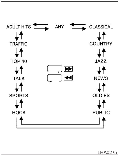
flowchart
graph TD
    A["ADULT HITS"] --> B["TRAFFIC"]
    B --> C["TOP 40"]
    C --> D["TALK"]
    D --> E["SPORTS"]
    E --> F["ROCK"]
    G["CLASSICAL"] --> H["COUNTRY"]
    H --> I["JAZZ"]
    I --> J["NEWS"]
    J --> K["OLDIES"]
    K --> L["PUBLIC"]
    M["ANY"] --> N["CLASSICAL"]
    N --> O["COUNTRY"]
    O --> P["JAZZ"]
    P --> Q["NEWS"]
    Q --> R["OLDIES"]
    R --> S["PUBLIC"]
    T["LHA0275"] --> U["Feedback Loop"]
    U --> V["Feedback Loop"]
- Press the TUNE button ( ◀◀ or ▶▶ ) to chose a specific program type. Refer to the illustration.
The display will show "SEEK, SCAN?"
SEEK tuning:
- After selecting a program type, push the SEEK button (◀ or ▶) for less than 1.5 seconds within 10 seconds. Tuning to the PTY station will start. If you do not push the SEEK button within the 10 second period, the PTY mode will be canceled.
SCAN tuning:
- Push the ◀ or ▶ button for more than 1.5 seconds to scan the PTY name stations and stop at each broadcasting station for 5 seconds. Pushing the button again during this 5 second period will stop SCAN tuning and the radio will remain tuned to that station. If the ◀ or ▶ button is not pushed within 5 seconds, SCAN tuning moves to the next station.
Compact disc (CD) changer operation

CAUTION
- Do not force a compact disc into the CD insert slot. This could damage the CD and/or CD changer/player.
- Trying to load a CD with the CD door closed could damage the CD and/or CD changer.
Turn the ignition key to the ACC or ON position and insert the compact disc into the slot with the label side facing up. The compact disc will be guided automatically into the slot and start playing. To insert the disc, first push the LOAD button.
If the radio is already operating, it will automatically turn off and the compact disc will play.
If the system has been turned off while the compact disc was playing, pushing the POWER/VOLUME control knob will start the compact disc.
LOAD button:
To insert a CD in the CD changer, push the LOAD button for less than 1.5 seconds. Select the loading slot by pushing the CD insert select button (1 - 6), then insert the CD.
To insert 6 CDs to the CD changer, push the LOAD button for more than 1.5 seconds.
The slot numbers (1 - 6) will illuminate on the display when CDs are loaded into the changer.
CD button:
When the CD button is pushed with the system off and the compact disc loaded, the system will turn on and the compact disc will start to play.
When the CD button is pushed with the compact disc loaded with the radio playing, the radio will automatically be turned off and the compact disc will start to play.
REW (Rewind), FF (Fast Forward):
When the ◀◀ (rewind) or ▶▶ (fast forward) button is pushed while a compact disc is playing, the compact disc will play while rewinding or fast forwarding. When the button is released, the compact disc will return to normal play speed.
When the CD button is pushed with the system off and the compact disc loaded, the system will turn on and the compact disc will start to play.
When the CD button is pushed with the compact disc loaded with the tape or the radio playing, the tape or radio will automatically be turned off and the compact disc will start to play.
SEEK/TRACK:
When the ◀ button is pushed for less than 1.5 seconds while a compact disc is playing, the track being played returns to its beginning. Push several times to skip back through tracks. The compact disc will go back the number of times the button is pushed.
When the ▶ button is pushed for less than 1.5 seconds while the compact disc is playing, the next track will start to play from its beginning. Push several times to skip through tracks. The compact disc will advance the number of times the button is pushed. (When the last track on the compact disc is skipped through, the first track will be played.)
When pushing the ◀ or ▶ button for more than 1.5 seconds, each track will play for about 10 seconds. To stop playing, push the ▶ button again.
CD select buttons:
To play another CD that has been loaded, push a CD select button (1 - 6).
REPEAT (RPT):
When the PROG/RPT play button is pushed while the compact disc is played, the play pattern can be changed as follows:
ALL DISC RPT → 1 DISC RPT → 1 TRACK RPT → ALL DISC RDM → 1 DISC RDM → ALL DISC RPT
ALL DISC RPT: All discs loaded will be repeated.
1 DISC RPT: The disc that is currently playing will be repeated.
1 TRACK RPT: The track that is currently playing will be repeated
ALL DISC RDM: Tracks from all discs will be played randomly
1 DISC RDM: Tracks from the disc that is currently playing will be played randomly
REAR AV:
Pushing the REAR AV button for less than 1.5 seconds turns the rear seat audio controller on. REAR CONT ON will display. Pushing it again will turn the rear seat audio controller off. REAR CONT OFF will display. If the vehicle is not equipped with a rear seat audio controller, the display will show "REAR AV N/A".
If a DVD is loaded in the DVD entertainment system (if so equipped), pushing the REAR AV button for more than 1.5 seconds will turn the DVD player on.
When the REAR AV button is pushed for more than 1.5 seconds with a DVD loaded and another audio source playing, the other source will automatically be turned off and the DVD will start to play.

(SPEAKER CONTROL) button:
Push this button to turn the rear speakers off and headphones on. Push this button again to turn rear seat speakers back on and headphones off.

CD EJECT:
Current disc:
- Press the slot number (1 – 6) for the desired disc, then press the ▲ button. The compact disc will be ejected. If the disc is not removed within 15 seconds, the disc will reload (except 3.1 in [8 cm] diameter compact discs).
All discs:
- Press and hold the ▲ button for more than 1.5 seconds. The compact discs will be ejected one by one. If a disc is not removed within 15 seconds, or the ▲ button is pressed again during the eject sequence, the entire disc eject sequence will be canceled.
When this button is pushed while the compact disc is being played, the compact disc will eject and the last source will be played.
CD IN indicator:
The slot numbers (1 - 6) will illuminate if CDs have been loaded into the changer.
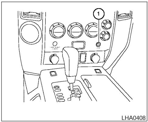
natural_image
Line drawing of a car interior showing dashboard, gear shift, and control panel (no text or symbols)AUX jack (if so equipped)
The AUX jack ① is located below the air conditioner controls. The AUX audio input jack accepts any standard analog audio input such as from a portable cassette tape player, MP3 player or laptop computers.
Press the AUX button to play a compatible device when it is plugged into the AUX jack.
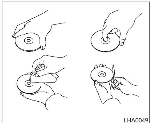
natural_image
Four line drawings showing hands holding circular objects, with one hand holding a circular object and another holding a pen (no text or symbols)CD CARE AND CLEANING
- Handle a CD by its edges. Do not bend the disc. Never touch the surface of the disc.
- Always place the discs in the storage case when they are not being used.
- To clean a disc, wipe the surface from the center to the outer edge using a clean, soft cloth. Do not wipe the disc using a circular motion.
- Do not use a conventional record cleaner or alcohol intended for industrial use.
- A new disc may be rough on the inner and outer edges. Remove the rough edges by rubbing the inner and outer edges with the side of a pen or pencil as illustrated.
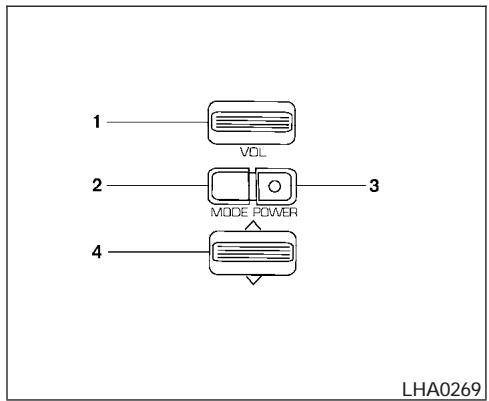
- Volume control switch
- MODE select switch
- POWER on/off switch
- Tuning switch
STEERING WHEEL SWITCH FOR AUDIO CONTROL (if so equipped)
The audio system can be operated using the controls on the steering wheel.
POWER on/off switch
With the ignition key turned to the ACC or ON position, push the POWER switch to turn the audio system on or off.
MODE select switch
Push the mode select switch to change the mode in the following sequence: PRESET A, PRESET B or PRESET C radio stations, CD and DVD (if so equipped).
Volume control switch
Push the volume control switch up or down to increase or decrease the volume.


Tuning
Memory change (radio):
Push the tuning switch ( √ or ∧ ) for less than 1.5 seconds to change the radio frequency.
Seek tuning (radio):
Push the tuning switch (√ or ∧) for more than 1.5 seconds to seek the next or previous radio station.
FF, REW:
Push the tuning switch (√ or ∧) for less 1.5 seconds to return to the beginning of the present program or skip to the next program. Push several times to skip back or skip through programs.
To stop the FF or REW function, press the √ or ∧ button for less than 1.5 seconds again.
When playing a CD in the CD changer (if so equipped), push the tuning switch (√ or ∧) for more than 1.5 seconds to change between discs when multiple CDs are loaded.
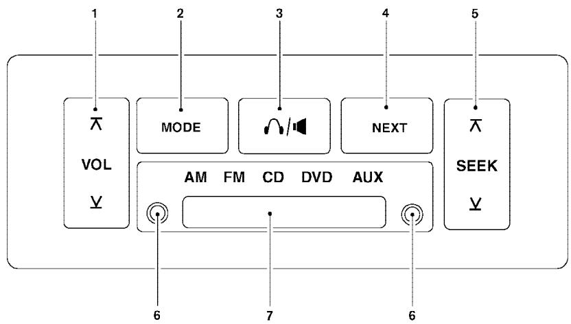
flowchart
graph TD
    A["1 VOL"] --> B["2 MODE"]
    B --> C["3 Speaker"]
    C --> D["4 NEXT"]
    D --> E["5 SEEK"]
    F["6 AM FM CD DVD AUX"] --> G["7 6"]
    style A fill:#f9f,stroke:#333
    style B fill:#ccf,stroke:#333
    style C fill:#cfc,stroke:#333
    style D fill:#fcc,stroke:#333
    style E fill:#cff,stroke:#333
LHA0322
- VOL (volume) control button
- MODE select button
- speaker control button
- NEXT button
- SEEK button
-
Headphone jacks
-
Infrared headphone transmitter lens*
*Red transmitters will be visible when infrared headphones are on.
REAR AUDIO CONTROLS (if so equipped)
Push the REAR AV button on the front radio control panel to turn the rear controls on. Push the button again to turn rear controls off.
The headphones symbol illuminates on the front display when the rear audio controls are on. Two headphone jacks are provided so two rear seat passengers may listen to the audio system privately.
The rear volume controls can only increase the volume to the level at which the front radio volume control is set.
One or two infrared headphones are included if the vehicle is equipped with the DVD entertainment system. Most portable radio headphones work with the rear audio controls.
For vehicles equipped with the FM/AM/SAT radio with compact disc player, if the rear passengers turn off the rear speakers and are using headphones they may choose to listen to a different media than the front passengers. The rear passengers can listen to the radio while the front passengers can listen to the same thing, a CD or SAT radio (if so equipped).
NISSAN MOBILE ENTERTAINMENT SYSTEM (MES) (if so equipped)
VOL (volume) button:
The VOL button allows the rear passengers to adjust the headphone volume level.

(SPEAKER CONTROL) button:
Push this button to turn the rear speakers off and headphones on. Push this button again to turn rear seat speakers back on and headphones off.
MODE button:
The MODE button allows the rear passengers to change between AM, FM, CD, DVD and AUX. The media options are listed on the face plate of the rear audio controls. When a source of media is selected, the media label will be illuminated.
SEEK button:
In AM or FM mode the SEEK button allows the rear seat passengers to find the next radio station up or down the station band frequency.
In CD mode the SEEK button allows the rear passengers to find the next or previous selection on the CD.
NEXT button:
When the NEXT button is pushed while in AM or FM mode, the radio will change to the next preset.
The NEXT button does not function while in SAT radio mode or when playing a DVD or CD.
ANTENNA
Window antenna
The antenna pattern is printed inside the rear passenger and driver side windows.
CAUTION
- Do not place metalized film near the rear driver or passenger side window glass or attach any metal parts to it. This may cause poor reception or noise.
- When cleaning the inside of the rear driver or passenger side window, be careful not to scratch or damage the window antenna. Lightly wipe along the antenna with a dampened soft cloth.
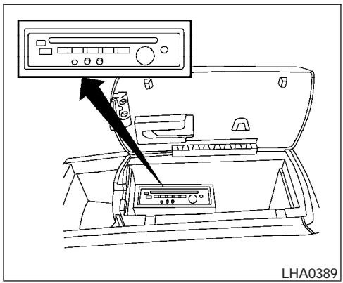
WARNING
- The Mobile Entertainment System is designed for rear seat passenger viewing only.
- The driver must not attempt to operate the Mobile Entertainment System while the vehicle is in motion so that full attention may be given to vehicle operation.

CAUTION
- The glass screen on the liquid crystal display may break if hit with a hard or sharp object. If the glass breaks, do not touch the liquid crystalline material, which contains a small amount of mercury. In case of contact with skin, wash immediately with soap and water.
- Use a damp, soft cloth when cleaning the Mobile Entertainment System components. Do not use solvents or cleaning solutions.
- Do not attempt to use the system in extreme temperature conditions [below -4°F (-20°C) or above 158°F (70°C)].
- To avoid draining the vehicle battery, do not operate the system more than 15 minutes without starting the engine.
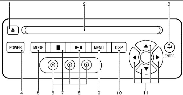
LHA0316
- EJECT button
- DVD slot
- ENTER button
- POWER on/off button
- MODE button
- Input jacks
- STOP button
- PLAY/PAUSE button
- MENU button
- DISPLAY button
- NAVIGATION keys
DIGITAL VIDEO DISC (DVD) PLAYER CONTROLS

The flip-down screen has a wireless remote control receiver ① located at the bottom of the screen.

CAUTION
- The glass screen on the liquid crystal display may break if hit with a hard or sharp object. If the glass breaks, do not touch the liquid crystalline material, which contains a small amount of mercury. In case of contact with skin, wash immediately with soap and water.
- The screen rotates down to view and up into the housing to store when not in use. Ensure that the screen is latched securely into the housing when stored.
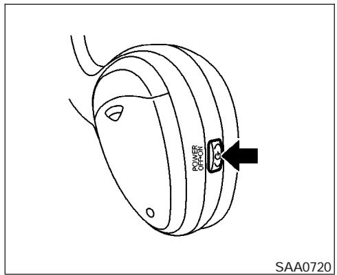
Headphones
Power ON/OFF:
Push the power button to turn the headphones on or off.
Volume control:
Turn the volume control knob to adjust the volume.
The headphones will automatically be turned off in 30 seconds if there is no sound during that period. To prevent the battery from being discharged, keep the power supply turned off when not in use.
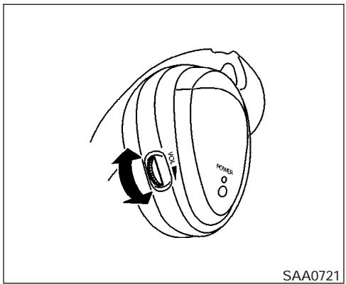
NOTE:
For optimum infrared headphone performance, increase the volume on the rear seat controller to the maximum level and adjust the infrared headphone volume using the volume control on the headphones. Using a lower volume setting on the rear seat controller can cause static noise in the infrared headphones.
PLAYING A DIGITAL VIDEO DISC (DVD)
CAUTION
- Only operate the DVD while the vehicle engine is running. Operating the DVD for extended periods of time with the engine OFF can discharge the vehicle battery.
- Do not allow the system to get wet. Excessive moisture such as spilled liquids may cause the system to malfunction.
- The driver must not attempt to wear the headphones while the vehicle is in motion so that full attention may be given to vehicle operation.
- While playing video CD media, this DVD player does not guarantee complete functionality of all video CD formats.
With the DVD player, you can hear DVD videos, video CDs and CDs using headphones. Passengers in the rear seat can enjoy the sound independently of the front seat.
Press the REAR AV button located on the front controls for more than 1.5 seconds to hear the sound of the DVD player through the speakers.
Pushing the ⏻ button on the front controls turns the rear speakers on and off.
It is possible to operate the DVD player by remote control.
Headphones are a wireless type and no cables are necessary. You can use them in almost all the ranges in the rear seat. (It is not possible to use the headphones in the front seat.)
POWER on/off button:
With the ignition switch turned to the ACC or ON position, push the POWER button to turn the DVD player on or off.
Insert the DVD into the slot with the label side facing up. The DVD will be guided automatically into the slot.
If the DVD player is off and a DVD is inserted, the DVD player will automatically turn on.
CAUTION
Do not force the compact disc into the slot. This could damage the player.
MODE select button:
Push the Mode button to select Audio/Video source between DVD and AUX input (input jacks
on the faceplate, Red = right channel audio input, White = left channel audio input, and Yellow = Video input).
The display will show the "AUX" in the upper left corner of the display for 4 seconds once the Mode is changed to AUX.
To use the input jacks, refer to “Auxiliary input jacks” in this section.
PLAY:
When the PLAY/PAUSE button on the player or the PLAY button on the remote control is pushed, the player will play.
In play mode, the display will briefly show on the upper left corner of the display.
FF (Fast Forward), REW (Remote control only):
Push FAST FORWARD/FAST REVERSE buttons to carry out the fast forward or fast reverse presentation at 5 times normal play speed.
Push FAST FORWARD/FAST REVERSE buttons again or PLAY button to resume the normal play speed.
NEXT CHAPTER/ PREVIOUS CHAPTER (Remote control only):
When the ▶▶▶ (NEXT CHAPTER) button is pushed while the DVD is being played, the program next to the present one will start to play from its beginning. Push several times to skip through programs. The DVD will advance the number of times the button is pushed. When the ◀◀ (PREVIOUS CHAPTER) button is pushed, the program being played returns to its beginning. Push several times to skip back through programs. The DVD will go back the number of times the button is pushed.
PAUSE:
When the PLAY/PAUSE button on the player or the PAUSE button on the remote control is pushed, the player will pause playing of the media. In pause mode, the player will show "II" on the upper left corner of the display until the player is changed to another mode.

STOP:
Push the STOP button once to stop playing the media. The display will show ■ in the upper left corner of the display for 4 seconds, and the last disc position will be stored. When the PLAY button is pushed again, it will resume at the stored disc track and time position.
If the STOP button is pushed again when the player is already in Stop mode, it will reinitialize the pointer to the beginning of the disc. In effect it will ignore the last stored disc position and upon receipt of the next play message it will begin at the Title Menu, or at “the beginning of the disc”.

EJECT:
When the EJECT button is pushed with the DVD loaded, it will be ejected.
The display will show the EJECT symbol in the upper left corner of the display for 4 seconds once the EJECT button is pushed.
If the DVD is not loaded, the display will show "NO DISC".
If the DVD comes out and is not removed within 25 seconds, it will be pulled back into the slot to protect it.
DISPLAY:
If the DISPLAY control is pushed for less than 2 seconds, the display menu will appear on the screen.
- The display menu will remain on the screen for 10 seconds if no subsequent control activations occur.
- Use NAVIGATION KEYS to navigate within the display menu, and use ENTER to select the item.
- Holding the DISPLAY control on the faceplate for longer than approximately 2 seconds while in the display menu will reset the display characteristics to their nominal values. (Faceplate feature only)
If the DISPLAY control button on the faceplate is pushed for more than 2 seconds, the media track/time information will be displayed along the bottom of the display. Pushing the DISPLAY control for more than 2 seconds will remove the media track/time information from the display. (Faceplate feature only)
NAVIGATION KEYS:
If media is in PLAY mode, activation of the NAVIGATION KEYS (Up, Down, Left, and Right) will perform the following functions: next chapter/track, previous chapter/track, fast reverse and fast forward, and the display will show ▶, ◀, ◀◀ and ▶▶ respectively in the upper left corner of the display for 4 seconds. (Faceplate feature only)
If media is in PAUSE mode, activation of the NAVIGATION KEYS (Up, Down and Right) will perform the following functions: next chapter/track, previous chapter/track and slow
forward, and the display will show ▶, ◀ and a forward arrow symbol respectively in the upper left corner of the display for 4 seconds. (Faceplate feature only)
If media is in activated MENU mode, the NAVIGATION KEYS will be used to navigate Up, Down, Left, and Right within the menu.
If display control menu is on, the NAVIGATION KEYS will be used to navigate Up, Down, Left, and Right within the menu.
ENTER:
In MENU mode, push the ENTER button to select MENU items.
In the display menu, push the ENTER button to select items for modification, as per the on-screen instructions.
MENU:
If the media is in PLAY mode and the MENU button is pressed, the DVD menu will appear on the screen. Use Navigation Keys to navigate within the menu, and use ENTER to select the item.
Push the MENU button again to return to PLAY mode.
TITLE (Remote control only):
Push TITLE button to return the DVD media to the "title" of the DVD.
Push TITLE button again to return to the previous stop point and play.
BACK (Remote control only):
Push the BACK button to exit the current active menu and return to the previous menu.
SUBTITLE (Remote control only):
Push the SUBTITLE button to call up subtitle selection menu.
Repeatedly press the SUBTITLE button to cycle through each available subtitle.
AUDIO (Remote control only):
Push the AUDIO button to call up audio menu.
Repeatedly press the AUDIO button to cycle through each available audio track.
ANGLE (Remote control only):
Push the ANGLE button to call up camera angle menu.
Repeatedly press the ANGLE button to cycle through each available angle.
CLEAR (Remote control only):
Push the CLEAR button to clear all numeric inputs, if actuated prior to expiration of the 3-second timer.
NUMERIC KEYPAD (0–9 & ≥10) (Remote control only):
Push the NUMERIC KEYPAD to directly access disc chapters, titles or tracks by inputting their numeric value.
The “≥10” button input numbers greater than or equal to 10, allowing up three digits to be input for selecting chapter/title/track number.
The subsequent actuation of numeric buttons will continuously shift the previously input number to the "left".
The chapter/title/track number will be automatically selected (if valid, based on media content) if 3 seconds expire without any keypad inputs.
The operator can cancel the input chapter/title/track number by actuating the CLEAR control prior to the expiration of the 3-second timer.
These functions can be used only for the DVD discs which correspond to them.
Auxiliary input jacks
The auxiliary input jacks are located on the control panel. Compatible devices such as video games camcorders and portable video players can be connected to the auxiliary jacks.
The auxiliary jacks are color coded for identification purposes.
- Yellow - video input
● White - left channel audio input - Red - right channel audio input
CARE AND MAINTENANCE
Use a lightly dampened, lint free cloth to clean the surfaces of your NISSAN mobile entertainment system. (DVD player face, screen, remote control, etc.)

CAUTION
- Do not use any solvents or cleaning solutions when cleaning the video system.
- Do not use excessive force on the monitor screen.
-
Avoid touching or scratching the monitor screen as it may become dirty or damaged.
-
Do not attempt to use the system in extreme temperature conditions [below -4°F (-20°C) or above 158°F (70°C)].
- Do not attempt to operate the system in extreme humidity conditions (less than 10% or more than 75%).
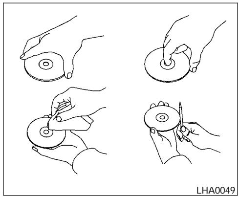
natural_image
Four hand-drawn diagrams showing a circular object being held, with one being held and others holding or adjusting it (no text or symbols)HOW TO HANDLE THE DVD

CAUTION
- Handle a DVD by its edges. Never touch the surface of the disc.
- To clean a disc, wipe the surface from the center to the outer edge using a clean, soft cloth. Do not wipe the disc using a circular motion.
-
Do not use a conventional record cleaner, benzine, thinner or alcohol intended for industrial use.
-
A new disc may be rough on its inner and outer edges. Remove the rough edges using the side of a pen or pencil as illustrated.
-
Never attempt to use a DVD that has been cracked, deformed, or repaired using adhesive. Doing so may cause damage to the equipment.
-
Handle the DVD carefully to avoid contamination or flaws. Otherwise, signals may not be read properly.
- Do not write, draw or attach anything on any side of the DVD.
- Do not store the DVD in locations with direct sunlight or in high temperatures or humidity.
- Always place discs in the storage case when they are not being used.
- Do not put on any sticker or write anything on either surface of the DVD.
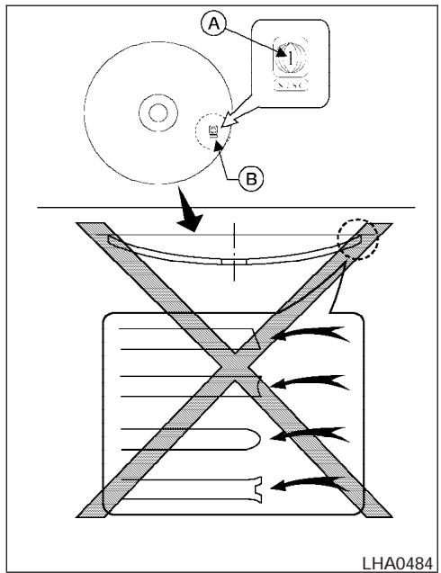
DVD player operation precautions
Do not use the following DVD's as they may cause the DVD player to malfunction:
• 3.1 in (8 cm) discs with an adapter
- DVD's with a region code other than "1". The region code A is displayed in a small symbol printed on the top of the DVD B
- DVD's that are not round
• DVD's with a paper label - DVD's that are warped, scratched, or have unequal edges
- Recordable digital video discs (DVD-R)
- Rewritable digital video discs (DVD-RW)
If a DVD with a paper label is used and becomes jammed you may be able to reset the unit and eject the jammed disc with the following procedure:
- Record the radio presets
- Disconnect the negative terminal from the battery for five minutes
- Reconnect the negative battery terminal
- Check to see if the jammed DVD has been ejected. If it has not, try to eject the DVD by pushing the eject button.
- If the disc cannot be ejected see your Nissan dealer for further assistance
- Re-program the radio presets
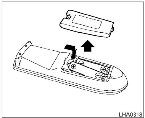
natural_image
Technical line drawing of a remote control device with an open lid and internal components, showing no text or symbols.Remote control and headphones battery replacement
Replace the battery as follows:
- Open the lid.
- Replace batteries with new ones.
- Size AA (remote control)
• Size AAA (headphones)
Make sure that the ⊕ and ⊖ ends on the batteries match the markings inside the compartment.
- Close the lid securely.
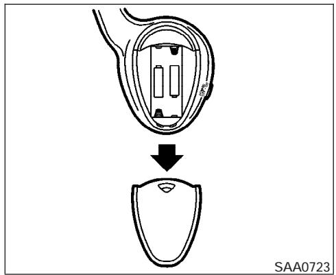
If the battery is removed for any reason other than replacement close the lid securely.
- If you will not be using the remote control for long periods of time, remove the batteries.
- Replacement of the batteries is needed when the remote control only functions at extremely close distances to the DVD player or not at all.
- Be careful not to touch the battery terminal.
- An improperly disposed battery can harm the environment. Always confirm local regulations for battery disposal.
- When changing batteries, do not let dust or oil get on the remote control and headphones.
FCC Notice:
Changes or modifications not expressly approved by the manufacturer compliance could void the user's authority to operate the equipment. This device complies with Part 15 of the FCC Rules and RSS-210 of Industry Canada. Operation is subject to the following two conditions: (1) This device may not cause harmful interference, and (2) this device must accept any interference received, including interference that may cause undesired operation of the device.
CAR PHONE OR CB RADIO
When installing a CB, ham radio or car phone in your NISSAN, be sure to observe the following cautions, otherwise the new equipment may adversely affect the engine control system and other electronic parts.

WARNING
- A cellular telephone should not be used while driving so full attention may be given to vehicle operation. Some jurisdictions prohibit the use of cellular telephones while driving.
- If you must make a call while your vehicle is in motion, the hands free cellular phone operational mode (if so equipped) is highly recommended. Exercise extreme caution at all times so full attention may be given to vehicle operation.
- If a conversation in a moving vehicle requires you to take notes, pull off the road to a safe location and stop your vehicle before doing so.

CAUTION
- Keep the antenna as far away as possible from the electronic control modules.
- Keep the antenna wire more than 8 in (20 cm) away from the electronic control system harnesses. Do not route the antenna wire next to any harness.
- Adjust the antenna standing-wave ratio as recommended by the manufacturer.
- Connect the ground wire from the CB radio chassis to the body.
- For details, consult a NISSAN dealer.
5 Starting and driving
Precautions when starting and driving....5-2
Exhaust gas (carbon monoxide) 5-2
Three-way catalyst....5-2
On-pavement and off-road driving precautions 5-3
Low tire pressure warning system 5-3
Avoiding collision and rollover....5-5
Drinking alcohol/drugs and driving....5-5
Driving safety precautions 5-5
Ignition switch....5-7
Automatic transmission....5-7
Key positions 5-7
Nissan vehicle immobilizer system (NVIS) ..... 5-8
Before starting the engine 5-8
Starting the engine 5-9
Driving the vehicle 5-9
Engine protection mode....5-9
Automatic transmission....5-10
Parking brake 5-14
Cruise control....5-14
Precautions on cruise control ....5-14
Cruise control operations....5-15
Break-in schedule 5-16
Increasing fuel economy....5-16
4x4 Using four wheel drive (4WD)....5-17
Transfer case shifting procedures .....5-17
Parking/parking on hills. 5-23
Power steering....5-24
Brake system 5-24
Brake precautions 5-24
Anti-lock brake system (ABS)....5-25
Vehicle dynamic control (VDC) system
(if so equipped) 5-26
Rear sonar system (if so equipped)....5-27
Cold weather driving....5-28
Freeing a frozen door lock....5-28
Anti-freeze....5-28
Battery 5-28
Draining of coolant water....5-28
Tire equipment 5-29
Special winter equipment....5-29
Driving on snow or ice 5-29
PRECAUTIONS WHEN STARTING AND DRIVING
WARNING
- Do not leave children or adults who would normally require the assistance of others alone in your vehicle. Pets should also not be left alone. They could accidentally injure themselves or others through inadvertent operation of the vehicle. Also, on hot, sunny days, temperatures in a closed vehicle could quickly become high enough to cause severe or possibly fatal injuries to people or animals.
- Properly secure all cargo with ropes or straps to help prevent it from sliding or shifting. Do not place cargo higher than the seatbacks. In a sudden stop or collision, unsecured cargo could cause personal injury.
EXHAUST GAS (carbon monoxide)
WARNING
- Do not breathe exhaust gases; they contain colorless and odorless carbon monoxide. Carbon monoxide is dangerous. It can cause unconsciousness or death.
- If you suspect that exhaust fumes are entering the vehicle, drive with all windows fully open, and have the vehicle inspected immediately.
- Do not run the engine in closed spaces such as a garage.
- Do not park the vehicle with the engine running for any extended length of time.
-
Keep the back door and rear vent windows closed while driving, otherwise exhaust gases could be drawn into the passenger compartment. If you must drive with the back door or rear vent windows open, follow these precautions:
-
Open all the windows.
- Set the 📄 air recirculation button to off and the fan control dial to high to circulate the air.
- If electrical wiring or other cable connections must pass to a trailer through the seal on the back door or the body, follow the manufacturer's recommendation to prevent carbon monoxide entry into the vehicle.
- The exhaust system and body should be inspected by a qualified mechanic whenever:
a. The vehicle is raised for service.
b. You suspect that exhaust fumes are entering into the passenger compartment.
c. You notice a change in the sound of the exhaust system.
d. You have had an accident involving damage to the exhaust system, underbody, or rear of the vehicle.
THREE-WAY CATALYST
The three-way catalyst is an emission control device installed in the exhaust system. Exhaust gases in the three-way catalyst are burned at high temperatures to help reduce pollutants.
WARNING
- The exhaust gas and the exhaust system are very hot. Keep people, animals or flammable materials away from the exhaust system components.
- Do not stop or park the vehicle over flammable materials such as dry grass, waste paper or rags. They may ignite and cause a fire.
CAUTION
- Do not use leaded gasoline. Deposits from leaded gasoline will seriously reduce the three-way catalyst's ability to help reduce exhaust pollutants.
- Keep your engine tuned up. Malfunctions in the ignition, fuel injection, or electrical systems can cause overrich fuel flow into the three-way catalyst, causing it to overheat. Do not keep driving if the engine misfires, or if noticeable loss of performance or other unusual operating conditions are detected. Have the vehicle inspected promptly by a NISSAN dealer.
- Avoid driving with an extremely low fuel level. Running out of fuel could cause the engine to misfire, damaging the three-way catalyst.
- Do not race the engine while warming it up.
- Do not push or tow your vehicle to start the engine.
ON-PAVEMENT AND OFF-ROAD DRIVING PRECAUTIONS
Utility vehicles have a significantly higher rollover rate than other types of vehicles.
They have higher ground clearance than passenger cars to make them capable of performing in a variety of on-pavement and off-road applications. This gives them a higher center of gravity than ordinary cars. An advantage of higher ground clearance is a better view of the road, allowing you to anticipate problems. However, they are not designed for cornering at the same speeds as conventional two-wheel drive vehicles any more than low-slung sports cars are designed to perform satisfactorily under off-road conditions. If at all possible, avoid sharp turns at high speeds. As with other vehicles of this type, failure to operate this vehicle correctly may result in loss of control or vehicle rollover. In a rollover crash, an unbelted person is significantly more likely to die than a person wearing a seat belt.
Be sure to read the driving safety precautions later in this section.
LOW TIRE PRESSURE WARNING SYSTEM
This vehicle is equipped with the low tire pressure warning system. It monitors tire pressure of all tires except the spare. When the tire pressure monitoring system warning light is lit, one or more of your tires is significantly under-inflated. If equipped, the system also displays pressure of all tires (except the spare tire) on the display screen by sending a signal from a sensor that is installed in each wheel.
The low tire pressure warning system will activate only when the vehicle is driven at speeds above 20 MPH (32 km/h). Also, this system may not detect a sudden drop in tire pressure (for example a flat tire while driving).
Tire pressure rises and falls depending on the heat caused by the vehicle's operation and the outside temperature. Low outside temperature can lower the temperature of the air inside the tire which can cause a lower tire inflation pressure. This may cause the low tire pressure warning light to illuminate.
If the warning light illuminates in low ambient temperature as described above, check the tire pressure for all four tires. Adjust the tire pressure to the recommended COLD tire pressure shown on the Tire and Loading Information label to turn the low tire pressure warning light OFF.
Frequently check the tire pressure information display on the display screen (if so equipped) and adjust pressure of each tire properly. (The order of the tire pressure figures displayed on the screen does not correspond with the actual order of the tire position.) See “Tire pressure information” in the “Display screen, heater, air conditioner and audio systems” section for tire pressure monitor. If you select the tire pressure information in the display (if so equipped), the FLAT TIRE warning message will be displayed.
Low tire pressure warning
If the vehicle is being driven with low tire pressure (lower than 28 psi, 193 kPa), the low tire pressure warning light comes on and the chime sounds for about 10 seconds.
For additional information regarding the above warning, see “Warning/indicator lights and audible reminders” in the “Instruments and controls” section.
WARNING
- If the low tire pressure warning light flashes while driving, avoid sudden steering maneuvers or abrupt braking, reduce vehicle speed, pull off the road to a safe location and stop the vehicle as soon as possible. Serious vehicle damage could occur and may lead to an accident and could result in serious personal injury. Check the tire pressure for all four tires. Adjust the tire pressure to the recommended COLD tire pressure shown on the Tire and Loading Information label to turn the low tire pressure warning light OFF. If you have a flat tire, replace it with a spare tire as soon as possible. (See “Flat tire” in the “In case of emergency” section for changing a flat tire.)
- When a spare tire is mounted or a wheel is replaced, tire pressure will not be indicated and the low tire pressure warning system will not function. Contact your NISSAN dealer as soon as possible for tire replacement and/or system resetting.
- Do not inject any tire liquid or aerosol tire sealant into the tires, as this may cause a malfunction of the tire pressure sensors.
CAUTION
Do not place metalized film or any metal parts (antenna, etc.) on the windows. This may cause poor reception of the signals from the tire pressure sensors, and the low tire pressure warning system will not function properly.
FCC Notice:
Changes or modifications not expressly approved by the manufacturer compliance could void the user's authority to operate the equipment.
This device complies with Part 15 of the FCC Rules and RSS-210 of Industry Canada.
Operation is subject to the following two conditions: (1) This device may not cause harmful interface, and (2) this device must accept any interference received, including interference that may cause undesired operation of the device.
Failure to operate this vehicle in a safe and prudent manner may result in loss of control or an accident.
Be alert and drive defensively at all times. Obey all traffic regulations. Avoid excessive speed, high speed cornering, or sudden steering maneuvers, because these driving practices could cause you to lose control of your vehicle. As with any vehicle, loss of control could result in a collision with other vehicles or objects, or cause the vehicle to roll over, particularly if the loss of control causes the vehicle to slide sideways. Be attentive at all times, and avoid driving when tired. Never drive when under the influence of alcohol or drugs (including prescription or over-the-counter drugs which may cause drowsiness). Always wear your seat belt as outlined in the “Safety – Seats, seat belts and supplemental restraint system” section of this manual, and also instruct your passengers to do so.
Seat belts help reduce the risk of injury in collisions and rollovers. In a rollover crash, an unbelted or improperly belted person is significantly more likely to be injured or killed than a person properly wearing a seat belt.
DRINKING ALCOHOL/DRUGS AND DRIVING
WARNING
Never drive under the influence of alcohol or drugs. Alcohol in the bloodstream reduces coordination, delays reaction time and impairs judgement. Driving after drinking alcohol increases the likelihood of being involved in an accident injuring yourself and others. Additionally, if you are injured in an accident, alcohol can increase the severity of the injury.
NISSAN is committed to safe driving. However, you must choose not to drive under the influence of alcohol. Every year thousands of people are injured or killed in alcohol-related accidents. Although the local laws vary on what is considered to be legally intoxicated, the fact is that alcohol affects all people differently and most people underestimate the effects of alcohol.
Remember, drinking and driving don't mix! And that is true for drugs, too (over-the-counter, prescription, and illegal drugs). Don't drive if your ability to operate your vehicle is impaired by alcohol, drugs, or some other physical condition.
DRIVING SAFETY PRECAUTIONS
Your NISSAN is designed for both normal and off-road use. However, avoid driving in deep water or mud as your NISSAN is mainly designed for leisure use, unlike a conventional off-road vehicle.
Remember that two-wheel drive models are less capable than four-wheel drive models for rough road driving and extrication when stuck in deep snow or mud, or the like.
Please observe the following precautions:
WARNING
- Drive carefully when off the road and avoid dangerous areas. Every person who drives or rides in this vehicle should be seated with their seat belt fastened. This will keep you and your passengers in position when driving over rough terrain.
-
Do not drive across steep slopes. Instead drive either straight up or straight down the slopes. Off-road vehicles can tip over sideways much more easily than they can forward or backward.
-
Many hills are too steep for any vehicle. If you drive up them, you may stall. If you drive down them, you may not be able to control your speed. If you drive across them, you may roll over.
- Do not shift gears while driving on downhill grades as this could cause loss of control of the vehicle.
- Stay alert when driving to the top of a hill. At the top there could be a drop-off or other hazard that could cause an accident.
- If your engine stalls or you cannot make it to the top of a steep hill, never attempt to turn around. Your vehicle could tip or roll over. Always back straight down in R (Reverse) gear and apply brakes to control your speed.
- Heavy braking going down a hill could cause your brakes to overheat and fade, resulting in loss of control and an accident. Apply brakes lightly and use a low gear to control your speed.
-
Unsecured cargo can be thrown around when driving over rough terrain. Properly secure all cargo so it will not be thrown forward and cause injury to you or your passengers.
-
To avoid raising the center of gravity excessively, do not exceed the rated capacity of the roof rack and evenly distribute the load. Secure heavy loads in the cargo area as far forward and as low as possible. Do not equip the vehicle with tires larger than specified in this manual. This could cause your vehicle to roll over.
- Do not grip the inside or spokes of the steering wheel when driving off-road. The steering wheel could move suddenly and injure your hands. Instead drive with your fingers and thumbs on the outside of the rim.
- Before operating the vehicle, ensure that the driver and all passengers have their seat belts fastened.
- Lower your speed when encountering strong crosswinds. With a higher center of gravity, your NISSAN is more affected by strong side winds. Slower speeds ensure better vehicle control.
- Do not drive beyond the performance capability of the tires, even with 4WD engaged.
- Accelerating quickly, sharp steering maneuvers or sudden braking may cause loss of control.
- If at all possible, avoid sharp turning maneuvers, particularly at high speeds. Your NISSAN four-wheel drive vehicle has a higher center of gravity than a two-wheel drive vehicle. The vehicle is not designed for cornering at the same speeds as conventional two-wheel drive vehicles. Failure to operate this vehicle correctly could result in loss of control and/or a rollover accident.
- Always use tires of the same type, size, brand, construction (bias, bias-belted, or radial), and tread pattern on all four wheels. Install tire chains on the rear wheels when driving on slippery roads and drive carefully.
- Be sure to check the brakes immediately after driving in mud or water. See "Brake system" later in this section for "Wet brakes".
- Avoid parking your vehicle on steep hills. If you get out of the vehicle and it rolls forward, backward or sideways, you could be injured.
- Whenever you drive off-road through sand, mud or water as deep as the wheel hub, more frequent maintenance may be required. See “Periodic maintenance” in the “NISSAN Service and Maintenance Guide.”
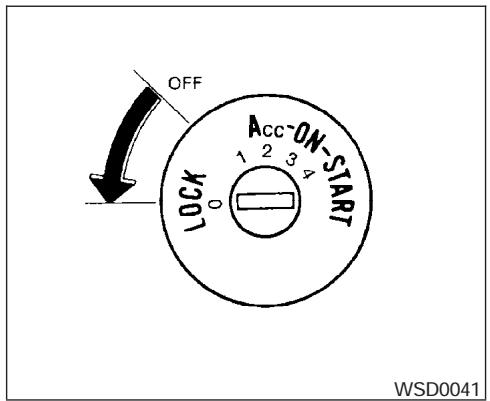
AUTOMATIC TRANSMISSION
The ignition lock is designed so the key cannot be turned to the LOCK position and removed until the shift selector lever is moved to the P (Park) position.
When removing the key from the ignition, make sure the shift selector lever is in the P (Park) position.
If the selector lever is not returned to P (Park) position, the key cannot be moved to the LOCK position.
To remove the key from the ignition switch:
- Shift the selector lever to the P (Park) position with the key in the ON position.
- Turn the key to the LOCK position.
- Remove the key from the ignition.
If the selector lever is shifted to the P (Park) position after the key is turned to the OFF position or when the key cannot be turned to the LOCK position, proceed as follows to remove the key.
- Move the shift selector lever into the P (Park) position.
- Turn the ignition key slightly toward the ON position.
- Turn the key to the LOCK position.
- Remove the key.
The shift selector lever is designed so it cannot moved out of P (Park) and into any of the other gear positions if the ignition key is turned to OFF position or if the key is removed from the switch.
The shift selector lever can be moved if the ignition switch is in the ON position and the foot brake pedal is depressed.
There is an OFF position between the LOCK and ACC positions. The OFF position is indicated by a "1" on the key cylinder.
When the ignition is in the OFF position, the steering wheel is not locked.
In order for the steering wheel to be locked, it must be turned about 1/8 of a turn clockwise from the straight up position.
To lock the steering wheel, turn the key to the LOCK position. Remove the key. To unlock the steering wheel, insert the key and turn it gently while rotating the steering wheel slightly right and left.
If the key will not turn from the LOCK position, turn the steering wheel to the left or right while turning the key to unlock the key cylinder.

WARNING
Never remove or turn the key to the LOCK position while driving. The steering wheel will lock. This may cause the driver to lose control of the vehicle and could result in serious vehicle damage or personal injury.
KEY POSITIONS
LOCK: Normal parking position (0)
OFF: (Not used) (1)
ACC: (Accessories) (2)
BEFORE STARTING THE ENGINE
This position activates electrical accessories such as the radio when the engine is not running.
ON: Normal operating position (3)
This position turns on the ignition system and the electrical accessories.
START: (4)
This position starts the engine. As soon as the engine has started, release the key. It automatically returns to the ON position.
NISSAN VEHICLE IMMOBILIZER SYSTEM (NVIS)
The NISSAN Vehicle Immobilizer System (NVIS) will not allow the engine to start without the use of the registered NVIS key.
If the engine fails to start using the registered NVIS key, it may be due to interference caused by another NVIS key, an automated toll road device or automated payment device on the key ring. Restart the engine using the following procedures:
- Leave the ignition switch in the ON position for approximately 5 seconds.
-
Turn the ignition switch to the OFF or LOCK position and wait approximately 10 seconds.
-
Repeat step 1 and 2 again.
- Restart the engine while holding the device (which may have caused the interference) separate from the registered NVIS key.
If this procedure allows the engine to start, NISSAN recommends placing the registered NVIS key on a separate key ring to avoid interference from other devices.
- Make sure the area around the vehicle is clear.
- Check fluid levels such as engine oil, coolant, brake fluid, and window washer fluid as frequently as possible, or at least whenever you refuel.
- Check that all windows and lights are clean.
- Visually inspect tires for their appearance and condition. Also check tires for proper inflation.
- Lock all doors.
- Position seat and adjust head restraints.
- Adjust inside and outside mirrors.
- Fasten seat belts and ask all passengers to do likewise.
- Check the operation of warning lights when the key is turned to the ON (3) position. See "Warning/indicator lights and audible reminders" in the "Instruments and controls" section of this manual.
STARTING THE ENGINE
- Apply the parking brake.
- Move the shift selector lever to P (Park) or N (Neutral). P (Park) is recommended.
The shift selector lever cannot be moved out of P (Park) and into any of the other gear positions if the ignition key is turned to the OFF position or if the key is removed from the ignition switch.
The starter is designed not to operate if the shift selector lever is in any of the driving positions.
- Crank the engine with your foot off the accelerator pedal by turning the ignition key to START. Release the key when the engine starts. If the engine starts, but fails to run, repeat the above procedure.
- If the engine is very hard to start in extremely cold weather or when restarting, depress the accelerator pedal a little (approximately 1/3 to the floor) and hold it and then crank the engine. Release the key and the accelerator pedal when the engine starts.
- If the engine is very hard to start because it is flooded, depress the accelerator pedal all the way to the floor and hold it. Crank the engine for 5-6 seconds. After cranking the engine, release the accelerator pedal. Crank the engine with your foot off the accelerator pedal by turning the ignition key to START. Release the key when the engine starts. If the engine starts, but fails to run, repeat the above procedure.
CAUTION
Do not operate the starter for more than 15 seconds at a time. If the engine does not start, turn the key off and wait 10 seconds before cranking again, otherwise the starter could be damaged.
- Allow the engine to idle for at least 30 seconds after starting. Do not race the engine while warming it up. Drive at moderate speed for a short distance first, especially in cold weather.
In cold weather, keep the engine running for a minimum of 2–3 minutes before shutting it off. Starting and stopping the engine over a short period of time may make the vehicle more difficult to start.
DRIVING THE VEHICLE
ENGINE PROTECTION MODE
The engine has an engine protection mode to reduce the chance of damage if the coolant temperature becomes too high (for example, when climbing steep grades in high temperature with heavy loads, such as when towing a trailer). When the engine temperature reaches a certain level:
- The engine coolant temperature gauge will move toward the H position.
- Engine power may be reduced.
- The air conditioning cooling function may be automatically turned OFF for a short time (the blower will continue to operate).
Engine power and, under some conditions, vehicle speed will decrease. Vehicle speed can be controlled with the accelerator pedal, but the vehicle may not accelerate at the desired speed. The transmission will downshift or upshift as it reaches prescribed shift points. You can also shift manually.
As driving conditions change and engine coolant temperature is reduced, vehicle speed can be increased using the accelerator pedal, and air conditioning cooling function will automatically be turned back ON.
If:
- The engine coolant temperature is not reduced.
- The air conditioning cooling function does not turn back ON.
- The engine oil pressure warning/engine coolant temperature high indicator illuminates, this may indicate a malfunction. Move the vehicle off the road in a safe area and allow the engine to cool. If after checking the oil and coolant, the remains on, do not continue to drive and call a NISSAN dealer.
The malfunction indicator lamp may also come ON. If only it remains on, you do not need to have your vehicle towed, but have it inspected soon by a NISSAN dealer. See “Malfunction indicator lamp” in the “Warning and indicator lights” section of this manual.
WARNING
Overheating can result in reduced engine power and vehicle speed. The reduced speed may be lower than other traffic, which could increase the chance of a collision. Be especially careful when driving. Pull to the side of the road to a safe area. Allow the engine to cool and return to normal operation. See “If your vehicle overheats” in the “In case of emergency” section of this manual.
CAUTION
Running the engine with the engine oil pressure warning light on could cause serious damage to the engine almost immediately. Such damage is not covered by warranty. Turn off the engine as soon as it is safe to do so.
AUTOMATIC TRANSMISSION
WARNING
- Do not depress the accelerator pedal while shifting from P (Park) or N (Neutral) to R (Reverse), or L (Low). Always depress the brake pedal until shifting is completed. Failure to do so could cause you to lose control and have an accident.
- Cold engine idle speed is high, so use caution when shifting into a forward or reverse gear before the engine has warmed up.
- Never shift to P (Park) or R (Reverse) while the vehicle is moving. This could cause an accident.
CAUTION
- When stopping the vehicle on an uphill grade, do not hold the vehicle by depressing the accelerator pedal. The foot brake should be used for this purpose.
- Do not downshift abruptly on slippery roads. This may cause a loss of control.
The automatic transmission in your vehicle is electronically controlled to produce maximum power and smooth operation.
The recommended operating procedures for this transmission are shown on the following pages. Follow these procedures for maximum vehicle performance and driving enjoyment.
Starting the vehicle
- After starting the engine, fully depress the foot brake pedal before attempting to move the shift selector lever out of the P (Park) position.
- Keep the foot brake pedal depressed and move the shift selector lever into a driving gear.
- Release the foot brake, then gradually start the vehicle in motion.
The automatic transmission is designed so the foot brake pedal MUST be depressed before shifting from P (Park) to any drive position while the ignition switch is in the ON position.
The shift selector lever cannot be moved out of P (Park) and into any of the other gear positions if the ignition key is turned to the LOCK, OFF or ACC position or if the key is removed.
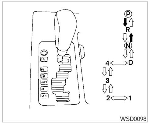
To move the selector lever:
→ : Shift while depressing the brake pedal
→ : Shift without depressing brake pedal
Shifting
After starting the engine, fully depress the brake pedal and move the shift selector lever out of the P (Park) position.
WARNING
Apply the parking brake if the selector lever is in any position while the engine is not running. Failure to do so could cause the vehicle to move unexpectedly or roll away and result in serious personal injury or property damage.
If the key is turned to the OFF or ACC position for any reason while the vehicle is in N (Neutral), or any D (Drive) position, the key cannot be turned to the LOCK position and be removed from the ignition switch. Move the selector lever to the P (Park) position, then the key can be turned to LOCK.
P (Park):
Use this selector position when the vehicle is parked or when starting the engine. Make sure the vehicle is completely stopped. The brake pedal must be depressed to move the selector lever from N (Neutral) or any drive position to P (Park). Apply the parking brake. When parking on a hill, apply the parking brake first, then move the shift selector lever into the P (Park) position.
R (Reverse):
CAUTION
Use this position only when the vehicle is completely stopped.
Use this position to back up. Make sure the vehicle is completely stopped before selecting the R (Reverse) position. The brake pedal must be depressed to move the selector lever from P (Park), N (Neutral) or any drive position to R (Reverse).
N (Neutral):
Neither forward nor reverse gear is engaged. The engine can be started in this position. You may shift to N (Neutral) and restart a stalled engine while the vehicle is moving.
D (Drive):
Use this position for all normal forward driving.
4 (Fourth gear):
Use this position for driving up and down long slopes where engine braking would be advantageous.
Do not downshift into the 4 position at speeds over the following and do not exceed the following speeds in the 4 position.
4H:
62 MPH (100 km/h)
4LO:
31 MPH (50 km/h)
3 (Third gear):
Use this position for driving up and down long slopes where engine braking would be advantageous.
2 (Second gear):
Use this position for hill climbing or engine braking on downhill grades.
Do not downshift into the 2 position at speeds over the following and do not exceed the following speeds in the 2 position.
2WD and AUTO:
71 MPH (115 km/h) w/o tow mode
62 MPH (100 km/h) w/tow mode
4H:
62 MPH (100 km/h)
4LO:
31 MPH (50 km/h)
1 (Low gear):
Use this position when climbing steep hills slowly or slow driving through deep snow, sand or mud, or for maximum engine braking on steep downhill grades.
Do not downshift into the 1 position at speeds over the following and do not exceed the following speeds in the 1 position.
2WD and AUTO:
43 MPH (70 km/h) w/o tow mode
37 MPH (60 km/h) w/tow mode
4H:
43 MPH (70 km/h) w/o tow mode
37 MPH (60 km/h) w/tow mode
4LO:
31 MPH (50 km/h)
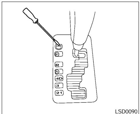
Shift lock release
If the battery is discharged, the shift selector lever may not be moved from the P (Park) position even with the brake pedal depressed.
To move the shift selector lever, release the shift lock. The shift selector lever can be moved to N (Neutral). However, the steering wheel will be locked unless the ignition switch is turned to the ON position. This allows the vehicle to be moved if the battery is discharged.
To push the shift lock release, complete the following procedure:
- Turn the ignition key to the LOCK position and remove the key
- Apply the parking brake.
- Remove the shift lock release cover as shown.
- Insert a small screwdriver in the shift lock release slot and push down.
- Move the shift selector lever to the N (Neutral) position while holding down the shift lock release.
- Turn the key to the ON position to unlock the steering wheel. Now the vehicle may be moved to the desired location.
If the shift selector lever cannot be moved out of P (Park), have a NISSAN dealer check the automatic transmission system as soon as possible.
WARNING
If the selector lever cannot be moved from the P (Park) position while the engine is running and the brake pedal is depressed, the stop lights may not work. Malfunctioning stop lights could cause an accident injuring yourself and others.
Accelerator downshift — in D position —
For passing or hill climbing, depress the accelerator pedal to the floor. This shifts the transmission down into a lower gear, depending on the vehicle speed.
Fail-safe
When the fail-safe operation occurs, please note that the transmission will be locked in any of the forward gears according to the condition.
If the vehicle is driven under extreme conditions, such as excessive wheel spinning and subsequent hard braking, the fail-safe system may be activated. This will occur even if all electrical circuits are functioning properly. In this case, turn the ignition key OFF and wait for 3 seconds. Then turn the key back to the ON position. The vehicle should return to its normal operating condition. If it does not return to its normal operating condition, have a NISSAN dealer check the transmission and repair it if necessary.

WARNING
- Be sure the parking brake is fully released before driving. Failure to do so can cause brake failure and lead to an accident.
- Do not release the parking brake from outside the vehicle.
- Do not use the gear shift in place of the parking brake. When parking, be sure the parking brake is fully engaged.
- Do not leave children unattended in a vehicle. They could release the parking brake and cause an accident.
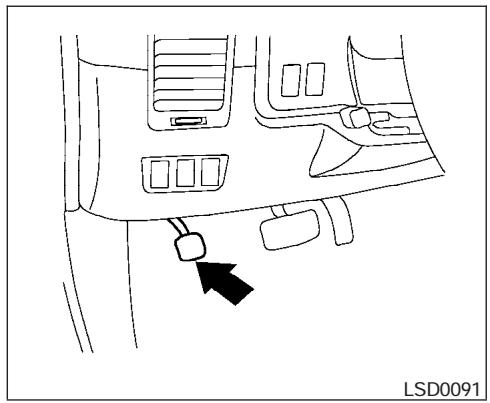
natural_image
Line drawing of a car interior showing dashboard and seat area with a black arrow pointing to the lower side (no text or symbols)To engage: Firmly depress the parking brake.
To release:
- Firmly apply the foot brake.
- Move the shift selector lever to the P (Park) position.
- Firmly depress the parking brake pedal and it will release.
- Before driving, be sure the brake warning light goes out.
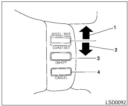
- ACCEL/RES switch
- COAST/SET switch
- ON/OFF switch
- CANCEL switch
PRECAUTIONS ON CRUISE CONTROL
- If the cruise control system malfunctions, it cancels automatically. The SET indicator light in the instrument panel then blinks to warn the driver.
- If the SET indicator light blinks, turn the cruise control main switch off and have the system checked by a NISSAN dealer.
- The SET indicator light may blink when the cruise control main switch is turned ON while pushing the ACCEL/RES, COAST/SET, or CANCEL switch (located on the steering wheel). To properly set the cruise control system, use the following procedures.
WARNING
Do not use the cruise control when driving under the following conditions:
- When it is not possible to keep the vehicle at a set speed.
- In heavy traffic or in traffic that varies in speed.
- On winding or hilly roads.
- On slippery roads (rain, snow, ice, etc.).
- In very windy areas.
Doing so could cause a loss of vehicle control and result in an accident.
The cruise control allows driving at a speed between 25 - 89 MPH (40 - 144 km/h) without keeping your foot on the accelerator pedal.
To turn on the cruise control, push the main switch. The CRUISE indicator light in the instrument panel comes on.
To set cruising speed, accelerate the vehicle to the desired speed, push the COAST/SET switch and release it. The SET indicator light in the instrument panel comes on. Take your foot off the accelerator pedal. Your vehicle maintains the set speed.
- To pass another vehicle, depress the accelerator pedal. When you release the pedal, the vehicle returns to the previously set speed.
- The vehicle may not maintain the set speed when going up or down steep hills. If this happens, drive without the cruise control.
To cancel the preset speed, use one of the following three methods.
- Push the CANCEL button; the SET indicator light in the instrument panel goes out.
- Tap the brake pedal; the SET indicator light goes out.
- Turn the main switch off. Both the CRUISE indicator light and SET indicator light in the instrument panel go out.
The cruise control is automatically canceled and the SET light in the instrument panel goes out if:
- you depress the brake pedal while pushing the ACCEL/RES or SET/COAST switch. The preset speed is deleted from memory.
- the vehicle slows down more than 8 MPH (13 km/h) below the set speed.
- you move the shift selector lever to N (Neutral).
To reset at a faster cruising speed, use one of the following three methods.
- Depress the accelerator pedal. When the vehicle attains the desired speed, push and release the COAST/SET switch.
- Push and hold the ACCEL/RES switch. When the vehicle attains the speed you desire, release the switch.
- Push and release the ACCEL/RES switch. Each time you do this, the set speed increases by about 1 MPH (1.6 km/h).
To reset at a slower cruising speed, use one of the following three methods.
- Lightly tap the brake pedal. When the vehicle attains the desired speed, push the COAST/SET switch and release it.
BREAK-IN SCHEDULE
- Push and hold the COAST/SET switch. Release the switch when the vehicle slows to the desired speed.
- Push and release the COAST/SET switch. Each time you do this, the set speed decreases by about 1 MPH (1.6 km/h).
To resume the preset speed, push and release the ACCEL/RES switch. The vehicle returns to the last set cruising speed when the vehicle speed is over 25 MPH (40 km/h).
CAUTION
During the first 1,200 miles (2,000 km), follow these recommendations to obtain maximum engine performance and ensure the future reliability and economy of your new vehicle. Failure to follow these recommendations may result in shortened engine life and reduced engine performance.
- Avoid driving for long periods at constant speed, either fast or slow, and do not run the engine over 4,000 rpm.
- Do not accelerate at full throttle in any gear.
- Avoid quick starts.
- Avoid hard braking as much as possible.
- Do not tow a trailer for the first 500 miles (800 km). Your engine, axle or other parts could be damaged.
INCREASING FUEL ECONOMY
- Accelerate slowly and smoothly. Maintain cruising speeds with a constant accelerator position.
- Drive at moderate speeds on the highway. Driving at high speed lowers fuel economy.
- Avoid unnecessary stopping and braking. Maintain a safe distance behind other vehicles.
- Use a proper gear range which suits road conditions. On level roads, shift into high gear as soon as possible.
- Avoid unnecessary engine idling.
- Keep your engine tuned up.
- Follow the recommended periodic maintenance schedule.
- Keep the tires inflated to the correct pressure. Low tire pressure increases tire wear and lowers fuel economy.
- Keep the front wheels in correct alignment. Improper alignment increases tire wear and lowers fuel economy.
-
Air conditioner operation lowers fuel economy. Use the air conditioner only when necessary.
-
When cruising at highway speeds, it is more economical to use the air conditioner and leave the windows closed to reduce drag.
- 4x4 Use 4H or 4L position only when necessary. Four-wheel drive operation lowers fuel economy.
CAUTION
- Do not drive the vehicle in the 4H or 4LO position on dry hard surface roads. Driving on dry, hard surfaces in 4H or 4LO may cause unnecessary noise, tire wear and increased fuel consumption.
If the 4WD warning light turns on when you are driving on dry hard surface roads:
- in the 4H position, shift the 4WD shift switch to 2WD.
- in the 4LO position, stop the vehicle, move the automatic transmission shift selector lever to the N position with the brake pedal depressed, and shift the 4WD shift switch to 2WD.
- If the warning light is still on after the above operation, have your vehicle checked by a NISSAN dealer as soon as possible.
- The transfer case may be damaged if you continue driving with the warning light blinking rapidly.
TRANSFER CASE SHIFTING PROCEDURES
All mode 4WD system provides 4 positions (AUTO, 2WD, 4H and 4LO), so you can select the desired drive mode according to the driving conditions.
2WD or 4WD shift procedure:
| 4WD Shift Switch Position | Wheels Driven | Indicator Light | Use Conditions | 4WD Shift Procedure | |
| 4WD shift | Transfer 4LO position | ||||
 AUTO AUTO | Rear wheels or 4 wheels |  | For driving on paved or slippery roads | Move the 4WD switch.2WD <--> AUTO <--> 4H4WD shift indicator light will indicate transfer shift position engaged.IT IS NOT NECESSARY TO MOVE THE AUTOMATIC TRANSMISSION SELECT LEVER TO THE N POSITION IN THIS OPERATION. PERFORM THIS OPERATION WHEN DRIVING STRAIGHT. | |
 2WD 2WD | Rear wheels |  | For driving on dry, paved roads (Economy drive) or state dynamometer I/M testing | ||
 4H 4H | 4 wheels |  | For driving on rocky, sandy or snow-covered roads | ||
| Neutral |  | *1 May blink | Neutral disengages the automatic transmission mechanical parking lock, which will allow the vehicle to roll. Do not leave the transfer shift position in Neutral.*2 | 1. Stop the vehicle.2. Move the automatic transmission selector lever to the N position.3. Push the 4WD shift switch and move it to 4LO or 4H with the brake pedal depressed.YOU CANNOT MOVE THE TRANSFER 4WD SHIFT SWITCH BETWEEN 4H AND 4LO (OR 4LO TO 4H)UNLESS YOU HAVE FIRST STOPPED THE VEHICLE, DEPRESSED THE BRAKE PEDAL AND MOVED THE AUTOMATIC TRANSMISSION SHIFT LEVER TO NEUTRAL. *3 | |
 4LO 4LO | |||||
| 4 wheels |  | Illuminated | For use when maximum power and traction is required (for example: on steep grades or rocky, sandy, muddy roads) | ||
*1: The transfer 4LO position indicator light may blink. Stop the vehicle. Be sure to shift the 4WD shift switch after the automatic transmission lever has been shifted to the N position. If the indicator light keeps blinking after the 4WD shift procedure in the previous page, drive slowly without abrupt maneuvers for a while. Then the light will turn on or off.
- Avoid making a turn or abrupt starts while shifting to 4LO. Otherwise gears may grind, damaging the drive system.
*2: While changing in and out of 4LO, the ignition key must be ON and the vehicle's engine must be running for a shift to take place and for the indicator lights (4WD shift and 4LO position indicator) to be operable. Otherwise, the shift will not take place and no indicator lights will be on or flashing.
*3: Make sure the transfer 4LO position indicator light turns on when you shift the 4WD shift switch to 4LO.
The transfer case 4WD shift switch is used to select either 2WD or 4WD depending on the driving conditions. There are four types of drive modes available, AUTO, 2WD, 4H and 4LO.
The 4WD shift switch electronically controls the transfer case operation. Rotate the switch to move between each mode, 2WD, AUTO, 4H and 4LO.
You must push the switch in to select 4LO, and the vehicle MUST be stationary and the automatic transmission selector lever in the N position when changing into or out of 4LO.
WARNING
When parking, apply the parking brake before stopping the engine and make sure that the 4WD shift indicator light is on and the ATP warning light goes off. Otherwise, the vehicle could unexpectedly move even if the automatic transmission is in the P position.
CAUTION
- Never shift the 4WD shift switch between 4LO and 4H while driving.
- The 4H position provides greater traction. Avoid excessive speed, as it will cause increased fuel consumption and higher oil temperatures, and could damage drivetrain components. Speeds over 62.5 MPH (100 km/h) in 4H is not recommended.
- The 4LO position provides maximum power and traction. Avoid raising vehicle speed excessively, as the maximum speed is approximately 31 MPH (50 km/h).
- When driving straight, shift the 4WD shift switch to the 2WD, AUTO or 4H position. Do not move the 4WD shift switch when making a turn or reversing.
- Do not shift the 4WD shift switch (between 2WD, AUTO and 4H) while driving on steep downhill grades. Use the engine brake and low automatic transmission gears (D1 or D2) for engine braking.
-
Do not operate the 4WD shift switch (between 2WD, AUTO and 4H) with the rear wheels spinning.
-
Do not drive on dry hard surface roads in the 4H or 4LO position. Driving on dry hard surfaces in 4H or 4LO may cause unnecessary noise and tire wear. NISSAN recommends driving in the 2WD or AUTO position under these conditions.
- The 4WD transfer case may not be shifted between 4H and 4LO at low ambient temperatures and the transfer 4LO position indicator light may blink even when the 4WD shift switch is shifted. After driving for a while you can change the 4WD transfer case between 4H and 4LO.
When driving on rough roads,
- Set the 4WD shift switch to AUTO, 4H or 4LO.
- Drive carefully according to the road surface conditions.
When the vehicle is stuck,
- Place stones or wooden blocks under the tires to free the vehicle.
-
Set the 4WD shift switch to 4H or 4LO.
-
If it is difficult to free the vehicle, repeat forward and backward movement to increase the movement.
- If the vehicle is stuck deep in mud, tire chains may be effective.

CAUTION
- Do not spin the tires excessively. Tires will sink deep into the mud, making it difficult to free the vehicle.
- Avoid shifting gears with the engine running at high speeds as this may cause malfunction.
4WD shift switch operations
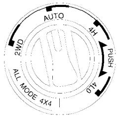
LSD0093
- Shift the 4WD shift switch to either the 2WD, AUTO, 4H or 4LO position, depending on driving conditions.
- With the switch set to the AUTO position, distribution of torque to the front and rear wheels changes automatically, depending on road conditions encountered [ratio; 0 : 100 (2WD) → 50 : 50 (4WD)]. This results in improved driving stability.
- If the 4WD shift switch is operated while making a turn, accelerating or decelerating or if the key switch is turned off while in the AUTO, 4H or
4LO, you may feel a jolt. This is not abnormal.
- When the vehicle is stopped after making a turn, you may feel a slight jolt after the selector lever is shifted to N or P. This occurs because the transfer clutch is released and not because of a malfunction.

CAUTION
- When driving straight, shift the 4WD shift switch to the 2WD, AUTO or 4H position. Do not move the 4WD shift switch when making a turn or reversing.
- Do not shift the 4WD shift switch while driving on steep downhill grades. Use the engine brake and low automatic transmission gears (D1 or D2) for engine braking.
- Do not operate the 4WD shift switch with the rear wheels spinning.
- Before placing the 4WD shift switch in the 4H position from 2WD or AUTO, ensure the vehicle speed is less than 62.5 MPH (100 km/h). Failure to do so can damage the 4WD system.
- Never shift the 4WD shift switch between 4LO and 4H while driving.
- Engine idling speed is high while warming up the engine. Be especially careful when starting or driving on slippery surfaces with the 4WD shift switch set in AUTO.
4WD shift indicator light
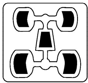
natural_image
Symmetrical abstract diagram with four connected circular shapes and central geometric shape (no text or symbols)LSD0094
The 4WD shift indicator light is located in the odometer display.
The light should turn off within 1 second after turning the ignition switch to the ON position.
While the engine is running, the 4WD shift indicator light will illuminate the position selected by the 4WD shift switch.
- The 4WD shift indicator light may blink while shifting from one drive mode to the other. When the shifting is completed, the 4WD shift indicator light will come on. If the indicator light does not come on immediately, make sure the area around the vehicle is safe, and
drive the vehicle straight, accelerate or decelerate or move the vehicle in reverse, then shift the 4WD shift switch.
- If the 4WD warning light comes on, the 4WD indicator light goes out.

CAUTION
- When the 4WD shift switch is turned to the AUTO position at low ambient temperatures, the 4WD shift indicator light may show 4H. If this happens, all four wheels are driven as torque distribution is in the 4H position. Be careful as the vehicle may become difficult to turn. When the vehicle is driven, the 4WD shift indicator light should change to AUTO.
- If the 4WD shift indicator light indication changes to 2WD when the 4WD shift switch is shifted to the AUTO or 4H position at low ambient temperatures, the 2WD mode may be being engaged due to malfunctioning drive system. If the indicator does not return to normal and the 4WD warning light comes on, have the system checked by the nearest NISSAN dealer.
4WD warning light
| Warning light | Comes on or blinks when: |
 Comes on Comes on | There is a malfunction in the 4-wheel drive system |
 Blinks rapidly Blinks rapidly | The transfer case oil temperature is abnormally high |
 Blinks slowly Blinks slowly | The difference in wheel rotation is large |
The 4WD warning light is located in the meter.
The 4WD warning light comes on when the key switch is turned to ON. It turns off soon after the engine is started.
If any malfunction occurs in the 4WD system when the key switch is ON, the warning light will either remain illuminated or blink.
If the 4WD warning light comes on, the 4WD shift indicator light goes out.
High-temperature transfer case oil makes the warning light blink rapidly (about twice per second). If the warning light blinks rapidly during operation, stop the vehicle in a safe place immediately. Then if the light goes off after a while, you can continue driving.
A large difference between the diameters of front and rear wheels will make the warning light blink slowly (about once per two seconds). Change the 4WD shift switch into 2WD and do not drive fast.
CAUTION
- If the warning light comes on or blinks slowly during operation or rapidly after stopping the vehicle for a while, have your vehicle checked by a NISSAN dealer as soon as possible.
- Shifting between 4H and 4LO is not recommended when the 4WD warning light turns on.
- When the warning light comes on, the 2WD mode may be engaged even if the 4WD shift switch is in AUTO or 4H. Be especially careful when driving. If corresponding parts are malfunctioning, the 4WD mode will not be engaged even if the 4WD shift switch is shifted.
- Do not drive the vehicle in the 4H or 4LO position on dry hard surface roads. Driving on dry, hard surfaces in 4H or 4LO may cause unnecessary noise, tire wear and increased fuel consumption.
If the 4WD warning light turns on when you are driving on dry hard surface roads:
- in the AUTO or 4H position, shift the 4WD shift switch to 2WD.
- in the 4LO position, stop the vehicle, move the automatic transmission shift selector lever to the N position with the brake pedal depressed, and shift the 4WD shift switch to 2WD.
- If the warning light is still on after the above operation, have your vehicle checked by a NISSAN dealer as soon as possible.
- The transfer case may be damaged if you continue driving with the warning light blinking rapidly.
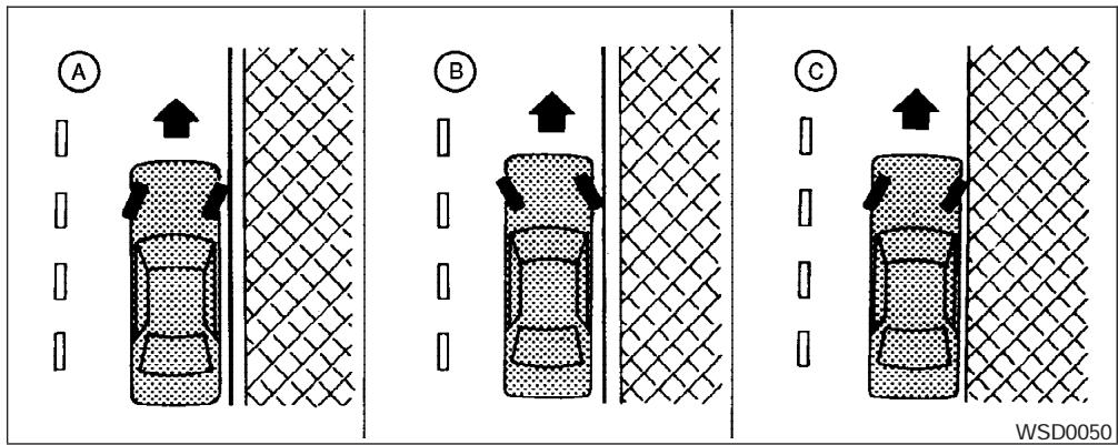
WARNING
- Do not stop or park the vehicle over flammable materials such as dry grass, waste paper or rags. They may ignite and cause a fire.
-
Safe parking procedures require that both the parking brake be set and the transmission placed into P (Park). Failure to do so could cause the vehicle to move unexpectedly or roll away and result in an accident. Make sure the shift lever has been pushed as far forward as it can go and cannot be moved without depressing the foot brake pedal.
-
Never leave the engine running while the vehicle is unattended.
-
Do not leave children unattended inside the vehicle. They could unknowingly activate switches or controls. Unattended children could become involved in serious accidents.
-
Firmly apply the parking brake.
-
Move the shift selector lever to the P (Park) position.
-
To help prevent the vehicle from rolling into traffic when parked on an incline, it is a good practice to turn the wheels as illustrated.
- HEADED DOWNHILL WITH CURB: Ⓐ
Turn the wheels into the curb and move the vehicle forward until the curb side wheel gently touches the curb.
- HEADED UPHILL WITH CURB: Ⓑ
Turn the wheels away from the curb and move the vehicle back until the curb side wheel gently touches the curb. - HEADED UPHILL OR DOWNHILL, NO CURB: ©
Turn the wheels toward the side of the road so the vehicle will move away from the center of the road if it moves.
- Turn the ignition key to the LOCK position and remove the key.
POWER STEERING
The power assisted steering uses a hydraulic pump, driven by the engine, to assist steering.
If the engine stops or the drive belt breaks, you will still have control of the vehicle. However, much greater steering effort is needed, especially in sharp turns and at low speeds.
WARNING
If the engine is not running or is turned off while driving, the power assist for the steering will not work. Steering will be much harder to operate.
BRAKE SYSTEM
The brake system has two separate hydraulic circuits. If one circuit malfunctions, you will still have braking at two wheels.
BRAKE PRECAUTIONS
Vacuum assisted brakes
The brake booster aids braking by using engine vacuum. If the engine stops, you can stop the vehicle by depressing the brake pedal. However, greater foot pressure on the brake pedal will be required to stop the vehicle and stopping distance will be longer.
Using the brakes
Avoid resting your foot on the brake pedal while driving. This will overheat the brakes, wear out the brakes and pads faster, and reduce gas mileage.
To help reduce brake wear and to prevent the brakes from overheating, reduce speed and downshift to a lower gear before going down a slope or long grade. Overheated brakes may reduce braking performance and could result in loss of vehicle control.
WARNING
- While driving on a slippery surface, be careful when braking, accelerating or downshifting. Abrupt braking or accelerating could cause the wheels to skid and result in an accident.
- If the engine is not running or is turned off while driving, the power assist for the brakes will not work. Braking will be harder.
Wet brakes
When the vehicle is washed or driven through water, the brakes may get wet. As a result, your braking distance will be longer and the vehicle may pull to one side during braking.
To dry the brakes, drive the vehicle at a safe speed while lightly pressing the brake pedal to heat up the brakes. Do this until the brakes return to normal. Avoid driving the vehicle at high speeds until the brakes function correctly.
Parking brake break-in
Break in the parking brake shoes whenever the stopping effect of the parking brake is weakened or whenever the parking brake shoes and/or drum/rotors are replaced, in order to assure the best brake performance.
This procedure is described in the vehicle service manual and can be performed by a NISSAN dealer.
The anti-lock brake system controls the brakes so the wheels do not lock when braking abruptly or when braking on slippery surfaces. The system detects the rotation speed at each wheel and varies the brake fluid pressure to prevent each wheel from locking and sliding. By preventing wheel lockup, the system helps the driver maintain steering control and helps to minimize swerving and spinning on slippery surfaces.
Using the system
Depress the brake pedal and hold it down.

WARNING
Do not pump the brake pedal. Doing so may result in increased stopping distances.
Normal operation
The anti-lock brake system does not operate at speeds below 3 - 6 MPH (5 - 10 km/h). (The speeds vary according to road conditions.)
When driving, the anti-lock brake system controls the wheels so they will not lock when braking abruptly or when braking on a slippery road. Thus, difficult steering and swerving of the vehicle due to locked wheels is minimized. The system detects the wheel rotation rate and electronically controls the pressure applied to each brake. Slight vibration on the brake pedal accompanied by noise usually occurs while the ABS system is operating. Such vibration and noise encountered during abrupt braking is not a problem, but indicates that the system is functioning properly. However, the pulsation may indicate that road conditions are hazardous and extra care is required while driving.
Self-test feature
The anti-lock brake system consists of electronic sensors and hydraulic solenoids controlled by a computer. The computer has a built-in diagnostic feature that tests the system each time you start the engine and move the vehicle at a low speed in forward or reverse. When the self-test occurs, you may hear a “clunk” noise and/or feel a pulsation in the brake pedal. This is normal and is not an indication of any malfunction. If the computer senses any malfunction, it switches the anti-lock brake system off and turns on the ABS brake warning light on the instrument panel. The brake system then operates normally, but without anti-lock assistance. If the light comes on during the self-test or while driving, take the vehicle to a NISSAN dealer for repair.

WARNING
- The anti-lock brake system is a sophisticated device, but it cannot prevent accidents resulting from careless or dangerous driving techniques. It can help maintain vehicle control during braking on slippery surfaces, but remember that the stopping distance on slippery surfaces will be longer than on normal surfaces even with the anti-lock brake system. Stopping distances may also be longer on rough, gravel or snow covered roads, or if you are using tire chains. Tire type and condition may also affect braking effectiveness. Always maintain a safe distance from the vehicle in front of you. Ultimately, the responsibility for safety of self and others rests in the hands of the driver.
- Tire type and condition of tires may also affect braking effectiveness.
- When replacing tires, install the specified size of tires on all four wheels.
VEHICLE DYNAMIC CONTROL (VDC) SYSTEM (if so equipped)
- When installing a spare tire, make sure it is the proper size and type as specified on the Tire and Loading Information label. For tire placard location information, refer to "Tire and Loading Information label" in the "Technical and consumer information" section of this manual.
- Refer to “Wheels and tires” in the “Maintenance and do-it-yourself” section of this manual.
When accelerating or driving on slippery surfaces, the tires may spin or slide. With the Vehicle Dynamic Control (VDC) system, sensors detect these movements and control the braking and engine output to help improve vehicle stability.
- When the vehicle dynamic control (VDC) system is operating, the slip indicator in the instrument panel blinks.
- If the slip indicator blinks, the road conditions are slippery. Be sure to adjust your speed and driving to these conditions. See "Slip indicator light", and "Vehicle dynamic control (VDC) off indicator light" in the "Instruments and controls" section.
- Indicator light
If malfunction occurs in the system, the SLIP and VDC indicator lights come on in the instrument panel.
As long as these indicator lights are on, the traction control function is canceled.
If the vehicle is operated with the vehicle dynamic control system off using the VDC OFF switch, most VDC functions will be turned off. The VDC system will still try to transfer power from a slipping drive wheel to one with more traction when the VDC system switch is OFF. The Slip indicator light will flash if wheel spin is detected. The ABS will still operate with the VDC system off.
When the VDC system is operating, you may feel a pulsation in the brake pedal and hear a noise or vibration from under the hood. This is normal and indicates that the VDC system is working properly.
The computer has a built in diagnostic feature that tests the system each time you start the engine and move the vehicle forward or in reverse at a slow speed. When the self-test occurs, you may hear a clunk noise and/or feel a pulsation in the brake pedal. This is normal and is not an indication of a malfunction.

WARNING
- The vehicle dynamic control system is designed to help improve driving stability but does not prevent accidents due to abrupt steering operation at high speeds or by careless or dangerous driving techniques. Reduce vehicle speed and be especially careful when driving and cornering on slippery surfaces and always drive carefully.
REAR SONAR SYSTEM (if so equipped)
- If brake related parts such as brake pads, rotors and calipers are not standard equipment or are extremely deteriorated, the vehicle dynamic control system may not operate properly and the vehicle dynamic control off indicator light may come on.
- Do not modify the vehicle's suspension. If suspension parts such as shock absorbers, struts, springs, stabilizer bars and bushings are not NISSAN approved for your vehicle or are extremely deteriorated the vehicle dynamic control system may not operate properly. This could adversely affect vehicle handling performance, and the VDC OFF indicator light may come on.
- When driving on extremely inclined surfaces such as higher banked corners, the vehicle dynamic control system may not operate properly and the VDC OFF indicator light may come on. Do not drive on these types of roads.
-
When driving on an unstable surface such as a turntable, ferry, elevator or ramp, the vehicle dynamic control off indicator light may illuminate. This is not a malfunction. Restart the engine after driving onto a stable surface
-
If wheels or tires other than the recommended ones are used, the vehicle dynamic control system may not operate properly and the vehicle dynamic control off indicator light may come on.
- The vehicle dynamic control system is not a substitute for winter tires or tire chains on a snow covered road.
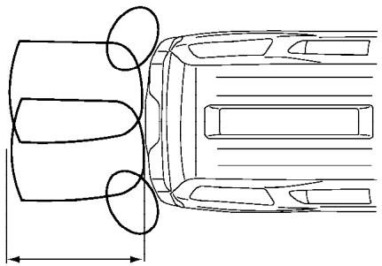
natural_image
Top-down line drawing of a car's side profile showing front and rear sections with no text or symbolsLSD0095
WARNING
- Always turn and look back before backing. The RSS is not a substitute for proper backing procedures.
- Read and understand the limitations of the rear sonar system as contained in this section. Inclement weather may affect the function of the RSS; this may include reduced performance or a false activation.
- This system is not designed to prevent contact with small or moving objects.
COLD WEATHER DRIVING
- The system is designed as an aid to the driver in detecting large stationary objects to help avoid damaging the vehicle. The system will not detect small objects below the bumper, and may not detect objects close to the bumper or on the ground.
- If your vehicle sustains damage to the rear bumper fascia, leaving it mis-aligned or bent, the sensing zone may be altered causing inaccurate measurement of obstacles or false alarms.
The Rear Sonar System (RSS) sounds a tone to warn the driver of obstacles near the rear bumper when the shift selector is in R (Reverse). The system may not detect objects at speeds above 3 mph (5 km/h) and may not detect certain angular or moving objects.
The RSS detects obstacles up to 6 feet (1.8 m) from the rear bumper with a decreased coverage area at the outer corners of the bumper, (refer to the illustration for approximate zone coverage areas). As you move closer to the obstacle, the rate of the tone increases. When the obstacle is less than 10 inches (25.0 cm) away, the tone will sound continuously. If the RSS detects a stationary or receding object further than 10 inches (25.0 cm) from the side of the vehicle, the tone will sound for only three seconds. Once the system detects an object approaching, the tone will sound again.
The RSS automatically turns on when the gear selector is placed in R (Reverse) and the ignition is ON. The RSS OFF switch on the instrument panel allows the driver to turn the RSS on and off. To turn the RSS off, the ignition must be ON, and the gear selector in R (Reverse). An indicator light on the switch will illuminate when the system is turned off. If the indicator light illuminates when the RSS is not turned off, it may indicate a failure in the RSS.
Keep the RSS sensors (located on the rear bumper fascia) free from snow, ice and large accumulations of dirt (do not clean the sensors with sharp objects). If the sensors are covered, it will affect the accuracy of the RSS.
FREEING A FROZEN DOOR LOCK
To prevent a door lock from freezing, apply de-icer through the key hole. If the lock becomes frozen, heat the key before inserting it into the key hole.
ANTI-FREEZE
In the winter when it is anticipated that the temperature will drop below 32irc F ( 0irc C), check the anti-freeze to assure proper winter protection. For details, see “Engine cooling system” in the “Maintenance and do-it-yourself” section of this manual.
BATTERY
If the battery is not fully charged during extremely cold weather conditions, the battery fluid may freeze and damage the battery. To maintain maximum efficiency, the battery should be checked regularly. For details, see “Battery” in the “Maintenance and do-it-yourself” section of this manual.
DRAINING OF COOLANT WATER
If the vehicle is to be left outside without anti-freeze, drain the cooling system, including the engine block. Refill before operating the vehicle.
For details, see “Changing engine coolant” in the “Maintenance and do-it-yourself” section of this manual.
TIRE EQUIPMENT
- SUMMER tires have a tread designed to provide superior performance on dry pavement. However, the performance of these tires will be substantially reduced in snowy and icy conditions. If you operate your vehicle on snowy or icy roads, NISSAN recommends the use of MUD & SNOW or ALL SEASON TIRES on all four wheels. Please consult a NISSAN dealer for the tire type, size, speed rating and availability information.
- For additional traction on icy roads, studded tires may be used. However, some U.S. states and Canadian provinces prohibit their use. Check local, state and provincial laws before installing studded tires.
Skid and traction capabilities of studded snow tires on wet or dry surfaces may be poorer than that of non-studded snow tires.
- Tire chains may be used.
Use of tire chains may be prohibited according to location. Check the local laws before installing tire chains. When installing tire chains, make sure they are of proper size for the tires on your vehicle and are installed according to the chain manufacturer's suggestions. Use only SAE Class "S" chains. Class "S" chains are used on vehicles with restricted tire to vehicle clearance. Vehicles that can use Class "S" chains are designed to meet the minimum clearances between the tire and the closest vehicle suspension or body component required to accommodate the use of a winter traction device (tire chains or cables). The minimum clearances are determined using the factory equipped tire size. Other types may damage your vehicle. Use chain tensioners when recommended by the tire chain manufacturer to ensure a tight fit. Loose end links of the tire chain must be secured or removed to prevent the possibility of whipping action damage to the fenders or underbody. If possible, avoid fully loading your vehicle when using tire chains. In addition, drive at a reduced speed. Otherwise, your vehicle may be damaged and/or vehicle handling and performance may be adversely affected.
Never install tire chains on spare tires. Do not use tire chains on dry roads.
SPECIAL WINTER EQUIPMENT
It is recommended that the following items be carried in the vehicle during winter:
- A scraper and stiff-bristled brush to remove ice and snow from the windows and wiper blades.
- A sturdy, flat board to be placed under the jack to give it firm support.
- A shovel to dig the vehicle out of snowdrifts.
- Extra window washer fluid to refill the reservoir tank.
DRIVING ON SNOW OR ICE

WARNING
- Wet ice (32°F, 0°C and freezing rain), very cold snow or ice can be slick and very hard to drive on. The vehicle will have much less traction or “grip” under these conditions. Try to avoid driving on wet ice until the road is salted or sanded.
-
Whatever the condition, drive with caution. Accelerate and slow down with care. If accelerating or downshifting too fast, the drive wheels will lose even more traction.
-
Allow more stopping distance under these conditions. Braking should be started sooner than on dry pavement.
- Allow greater following distances on slippery roads.
- Watch for slippery spots (glare ice). These may appear on an otherwise clear road in shaded areas. If a patch of ice is seen ahead, brake before reaching it. Try not to brake while on the ice, and avoid any sudden steering maneuvers.
- Do not use the cruise control on slippery roads.
- Snow can trap dangerous exhaust gases under your vehicle. Keep snow clear of the exhaust pipe and from around your vehicle.
6 In case of emergency
Flat tire....6-2
Low tire pressure warning system 6-2
Changing a flat tire 6-2
Jump starting 6-7
Push starting....6-9
If your vehicle overheats....6-9
Towing your vehicle....6-10
Towing recommended by NISSAN 6-11
Vehicle recovery (freeing a stuck vehicle)....6-12
LOW TIRE PRESSURE WARNING SYSTEM
This vehicle is equipped with the low tire pressure warning system. It monitors tire pressure of all tires except the spare. When the tire pressure monitoring system warning light is lit, one or more of your tires is significantly under-inflated. If equipped, the system also displays pressure of all tires (except the spare tire) on the display screen by sending a signal from a sensor that is installed in each wheel. If the vehicle is being driven with low tire pressure (lower than 28 psi, 193 kPa), the low tire pressure warning system will activate and warn you of it by the low tire pressure warning light. This system will activate only when the vehicle is driven at speeds above 20 MPH (32 km/h). For more details, refer to "Warning/indicator lights and audible reminders" in the "Instruments and controls" section, "Tire pressure information" in the "Display screen, heater, air conditioner and audio systems" section and "Low tire pressure warning system" in the "Starting and driving" section.
WARNING
- If the low tire pressure warning light flashes while driving, avoid sudden steering maneuvers or abrupt braking, reduce vehicle speed, pull off the road to a safe location and stop the vehicle as soon as possible. Serious vehicle damage could occur and may lead to an accident and could result in serious personal injury. Check the tire pressure for all four tires. Adjust the tire pressure to the recommended COLD tire pressure shown on the Tire and Loading Information label to turn the low tire pressure warning light OFF. If you have a flat tire, replace it with a spare tire as soon as possible.
- When a spare tire is mounted or a wheel is replaced, tire pressure will not be indicated and the low tire pressure warning system will not function. Contact your NISSAN dealer as soon as possible for tire replacement and/or system resetting.
- Do not inject any tire liquid or aerosol tire sealant into the tires, as this may cause a malfunction of the tire pressure sensors.
CHANGING A FLAT TIRE
If you have a flat tire, follow the instructions below.
Stopping the vehicle
- Safely move the vehicle off the road and away from traffic.
- Turn on the hazard warning flashers.
- Park on a level surface and apply the parking brake. Shift the transmission into P (Park).
- Turn off the engine.
- Raise the hood to warn other traffic and to signal professional road assistance personnel that you need assistance.
- Have all passengers get out of the vehicle and stand in a safe place, away from traffic and clear of the vehicle.
WARNING
- Make sure the parking brake is securely applied and the automatic transmission is shifted into P (Park).
-
Never change tires when the vehicle is on a slope, ice or slippery areas. This is hazardous.
-
Never change tires if oncoming traffic is close to your vehicle. Wait for professional road assistance.
- When a spare tire is mounted or a wheel is replaced, tire pressure will not be indicated and the low tire pressure warning system will not function. Contact your NISSAN dealer as soon as possible for tire replacement and/or system resetting.
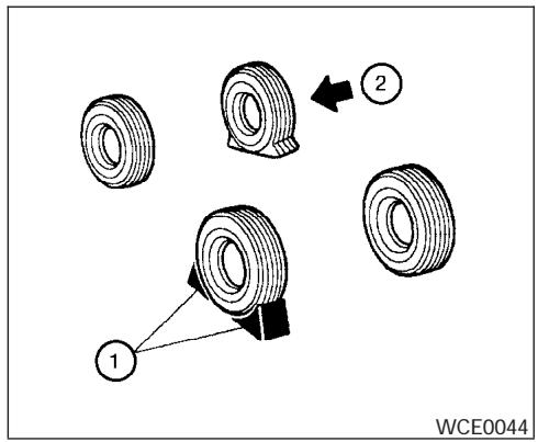
Blocking wheels
Place suitable blocks ① at both the front and back of the wheel diagonally opposite the flat tire ② to prevent the vehicle from moving when it is jacked up.

WARNING
Be sure to block the wheel as the vehicle may move and result in personal injury.
Getting the spare tire and tools
- Remove the jack tool kit from the floor storage area in the cargo area.
- Remove the cargo area storage bin cover.
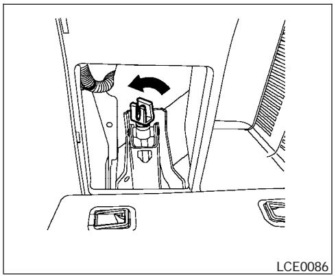
natural_image
Technical line drawing of a car interior showing a valve mechanism and directional arrow (no text or symbols)- Unscrew and remove the jack.
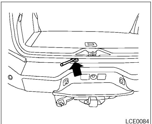
natural_image
Technical line drawing of a car interior showing dashboard and seat components (no text or symbols)- Assemble the two pieces of the jack rod. Find the oval-shaped opening above the middle of the license plate. Pass the T-shaped end of the jack rod through the opening and direct it toward the spare tire winch, located directly above the spare tire.
CAUTION
Do not insert the jack rod straight as it is designed to be inserted at an angle as shown.
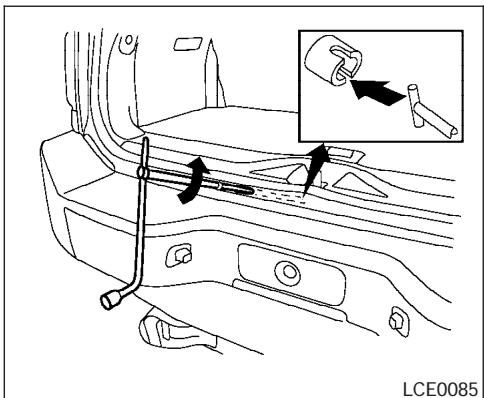
- Fit the square end of the jack rod into the square hole of the wheel nut wrench to form a handle.
- Seat the T-shaped end of the jack rod into the T-shaped opening of the tire winch. Apply pressure to keep the jack rod engaged in the spare tire winch and turn the jack rod counterclockwise to lower the spare tire.
- Once the spare tire is completely lowered, reach under the vehicle, remove the retainer chain, and carefully slide the tire from under the rear of the vehicle.
CAUTION
Be sure to center the spare tire suspending plate on the wheel and then lift the spare tire.
Jacking up vehicle and removing the damaged tire
WARNING
- Never get under the vehicle while it is supported only by the jack. If it is necessary to work under the vehicle, support it with safety stands.
- Use only the jack provided with your vehicle to lift the vehicle. Do not use the jack provided with your vehicle on other vehicles. The jack is designed for lifting only your vehicle during a tire change.
- Use the correct jack-up points. Never use any other part of the vehicle for jack support.
- Never jack up the vehicle more than necessary.
-
Never use blocks on or under the jack.
-
Do not start or run the engine while vehicle is on the jack. It may cause the vehicle to move. This is especially true for vehicles with limited slip differentials.
- Do not allow passengers to stay in the vehicle while it is on the jack.
- Never run the engine with a wheel(s) off the ground. It may cause the vehicle to move.
Always refer to the illustration for the correct placement and jack-up points for your specific vehicle model and jack type.
Carefully read the caution label attached to the jack body and the following instructions.
- Loosen each wheel nut one or two turns by turning counterclockwise with the wheel nut wrench. Do not remove the wheel nuts until the tire is off the ground.
NOTE:
Before jacking up the vehicle, make sure the ignition key is in the OFF position. If the vehicle is lifted up with the ignition key in the ON position the auto-leveling suspension (if so equipped) will become disabled after 60 seconds. To reset the auto-leveling suspension, cycle the ignition key ON/OFF one time.

natural_image
Side view line drawing of a car with two upward arrows indicating motion or movement (no text or symbols)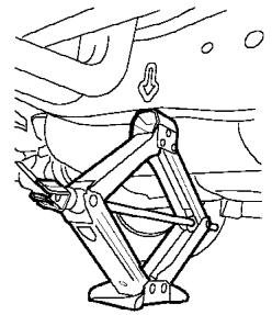
natural_image
Technical line drawing of a mechanical linkage assembly (no text or symbols)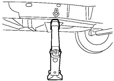
natural_image
Technical line drawing of a mechanical assembly with a vertical support and curved components (no text or symbols)WCE0097
- Place the jack directly under the jack-up point as illustrated so the top of the jack contacts the vehicle at the jack-up point. The jack-up points are indicated by stamped arrows on the side of the frame.
The jack should be used on firm and level ground.
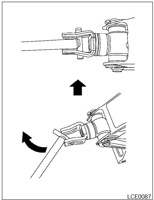
natural_image
Technical illustration showing two mechanical assembly steps with arrows indicating motion (no text or symbols)- Install the assembled jack rod into the jack as shown.
-
To lift the vehicle, securely hold the jack lever and rod. Carefully raise the vehicle until the tire clears the ground.
-
Remove the wheel nuts and then remove the tire.

Installing the spare tire
The spare tire is designed for emergency use. See specific instructions under the heading “Wheels and tires” in the “Maintenance and do-it-yourself” section of this manual.
- Clean any mud or dirt from the surface between the wheel and hub.
- Carefully put the spare tire on and tighten the wheel nuts finger tight.
- With the wheel nut wrench, tighten wheel nuts alternately and evenly as illustrated until they are tight.
JUMP STARTING
- Lower the vehicle slowly until the tire touches the ground. Then, with the wheel nut wrench, tighten the wheel nuts securely in the sequence illustrated. Lower the vehicle completely.

WARNING
- Incorrect wheel nuts or improperly tightened wheel nuts can cause the wheel to become loose or come off. This could cause an accident.
- Do not use oil or grease on the wheel studs or nuts. This could cause the nuts to become loose.
Retighten the wheel nuts after the vehicle has been driven for 600 miles (1,000 km) (also in cases of a flat tire, etc.). As soon as possible, tighten the wheel nuts to the specified torque with a torque wrench.
Wheel nut tightening torque:
98 ft-lb (133 N·m)
The wheel nuts must be kept tightened to specification at all times. It is recommended that wheel nuts be tightened to specifications at each lubrication interval.
Adjust tire pressure to the COLD pressure.
COLD pressure: After vehicle has been parked for three hours or more or driven less than 1 mile (1.6 km).
COLD tire pressures are shown on the Tire and Loading Information label affixed to the driver side center pillar.
- Securely store the flat tire and jacking equipment in the vehicle.

WARNING
- Always make sure that the spare tire and jacking equipment are properly secured after use. Such items can become dangerous projectiles in an accident or sudden stop.
- The spare tire is designed for emergency use. See specific instructions under the heading “Wheels and tires” in the “Maintenance and do-it-yourself” section of this manual.
To start your engine with a booster battery, the instructions and precautions below must be followed.

WARNING
- If done incorrectly, jump starting can lead to a battery explosion, resulting in severe injury or death. It could also damage your vehicle.
- Explosive hydrogen gas is always present in the vicinity of the battery. Keep all sparks and flames away from the battery.
- Do not allow battery fluid to come into contact with eyes, skin, clothing or painted surfaces. Battery fluid is a corrosive sulfuric acid solution which can cause severe burns. If the fluid should come into contact with anything, immediately flush the contacted area with water.
- Keep battery out of the reach of children.
-
The booster battery must be rated at 12 volts. Use of an improperly rated battery can damage your vehicle.
-
Whenever working on or near a battery, always wear suitable eye protectors (for example, goggles or industrial safety spectacles) and remove rings, metal bands, or any other jewelry. Do not lean over the battery when jump starting.
- Do not attempt to jump start a frozen battery. It could explode and cause serious injury.
- Your vehicle has an automatic engine cooling fan. It could come on at any time. Keep hands and other objects away from it.
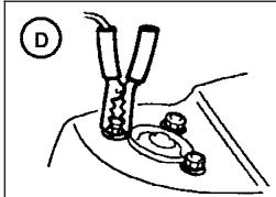
natural_image
Diagram of a mechanical assembly with two cylindrical components and a base, no visible text or symbols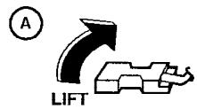
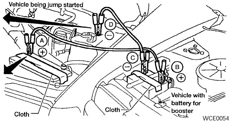
WARNING
Always follow the instructions below. Failure to do so could result in damage to the charging system and cause personal injury.
- If the booster battery is in another vehicle, position the two vehicles to bring their batteries near each other.
Do not allow the two vehicles to touch.
-
Apply the parking brake. Shift the transmission into P (Park). Switch off all unnecessary electrical systems (lights, heater, air conditioner, etc.).
-
Remove vent caps on the battery (if so equipped). Cover the battery with an old cloth to reduce explosion hazard.
- Connect jumper cables in the sequence illustrated (A, B, C, D).
CAUTION
- Always connect positive (+) to positive (+) and negative (−) to body ground (for example, strut mounting bolt, engine lift bracket, etc.) — not to the battery.
PUSH STARTING
- Make sure the jumper cables do not touch moving parts in the engine compartment and that the cable clamps do not contact any other metal.
- Start the engine of the booster vehicle and let it run for a few minutes.
- Keep the engine speed of the booster vehicle at about 2,000 rpm, and start the engine of the vehicle being jump started.

CAUTION
Do not keep the starter motor engaged for more than 10 seconds. If the engine does not start right away, turn the key off and wait 3 to 4 seconds before trying again.
- After starting the engine, carefully disconnect the negative cable and then the positive cable.
- Replace the vent caps (if so equipped). Be sure to dispose of the cloth used to cover the vent holes as it may be contaminated with corrosive acid.

CAUTION
Automatic transmission models cannot be push-started or tow-started. Attempting to do so may cause transmission damage.
IF YOUR VEHICLE OVERHEATS

WARNING
- Do not continue to drive if your vehicle overheats. Doing so could cause engine damage or a vehicle fire.
- To avoid the danger of being scalded, never remove the radiator or coolant reservoir cap while the engine is still hot. When the radiator or coolant reservoir cap is removed, pressurized hot water will spurt out, possibly causing serious injury.
- Do not open the hood if steam is coming out.
If your vehicle is overheating (indicated by an extremely high temperature gauge reading and the illumination of the engine oil pressure/engine coolant temperature high indicator light), or if you feel a lack of engine power, detect abnormal noise, etc. take the following steps.
- Move the vehicle safely off the road, apply the parking brake and move the shift lever to P (Park).
Do not stop the engine.
- Turn off the air conditioner. Open all the windows, move the heater or air conditioner temperature control to maximum hot and fan control to high speed.
TOWING YOUR VEHICLE
- Get out of the vehicle. Look and listen for steam or coolant escaping from the radiator before opening the hood. (If steam or coolant is escaping, turn off the engine.) Do not open the hood further until no steam or coolant can be seen.
- Open the engine hood.
WARNING
If steam or water is coming from the engine, stand clear to prevent getting burned.
5. Visually check drive belts for damage or looseness. Also check if the cooling fan is running. The radiator hoses and radiator should not leak water. If coolant is leaking, the water pump belt is missing or loose, or the cooling fan does not run, stop the engine.
WARNING
Be careful not to allow your hands, hair, jewelry or clothing to come into contact with, or get caught in, engine belts or the engine cooling fan. The engine cooling fan can start at any time when the coolant temperature is high.
- After the engine cools down, check the coolant level in the engine coolant reservoir tank with the engine running. Add coolant to the engine coolant reservoir tank if necessary. Have your vehicle repaired at a NISSAN dealer.
When towing your vehicle, all State (Provincial in Canada) and local regulations for towing must be followed. Incorrect towing equipment could damage your vehicle. Towing instructions are available from a NISSAN dealer. Local service operators are generally familiar with the applicable laws and procedures for towing. To assure proper towing and to prevent accidental damage to your vehicle, NISSAN recommends having a service operator tow your vehicle. It is advisable to have the service operator carefully read the following precautions:
WARNING
- Never ride in a vehicle that is being towed.
- Never get under your vehicle after it has been lifted by a tow truck.
CAUTION
- When towing, make sure that the transmission, axles, steering system and powertrain are in working condition. If any unit is damaged, dollies must be used.
- Always attach safety chains before towing.
For information about towing your vehicle behind a recreational vehicle (RV), refer to “Flat towing” in the “Technical and consumer information” section of this manual.
TOWING RECOMMENDED BY NISSAN
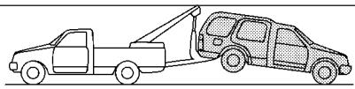
natural_image
Line drawing of a pickup truck and a car with a crane, no text or symbols present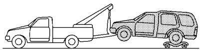
natural_image
Line drawing of two toy vehicles, one moving a tow truck and the other a van with wheels (no text or symbols)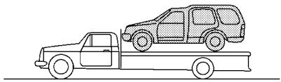
natural_image
Line drawing of a flatbed truck with a parked van on top (no text or symbols)ACE1037
Two-wheel drive models
NISSAN recommends that your vehicle be towed with the driving (rear) wheels off the ground or place the vehicle on a flat bed truck as illustrated.

CAUTION
- Never tow automatic transmission models with the rear wheels on the ground or four wheels on the ground (forward or backward), as this may cause serious and expensive damage to the transmission. If it is necessary to tow the vehicle with the front wheels raised always use towing dollies under the rear wheels.
- When towing automatic transmission models with the front wheels on the ground or on towing dollies:
- Turn the ignition key to the OFF position, and secure the steering wheel in a straight-ahead position with a rope or similar device. Never secure the steering wheel by turning the ignition key to the LOCK position. This may damage the steering lock mechanism.
If the speed or distance must necessarily be greater, remove the propeller shaft before towing to prevent damage to the transmission.
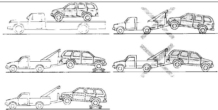
WSD0097
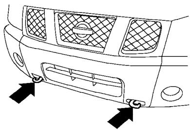
natural_image
Line drawing of a car's front bumper and side panel, showing grille and vent slots (no text or symbols)LCE0083
Four-wheel drive models
NISSAN recommends that towing dollies be used when towing your vehicle or place the vehicle on a flat bed truck as illustrated.
CAUTION
- Never tow 4WD models with any of the wheels on the ground as this may cause serious and expensive damage to the transfer case and transmission.
VEHICLE RECOVERY (freeing a stuck vehicle)
WARNING
- Stand clear of a stuck vehicle.
- Do not spin your tires at high speed. This could cause them to explode and result in serious injury. Parts of your vehicle could also overheat and be damaged.
CAUTION
- Tow chains or cables must be attached only to the main structural members of the vehicle or the towing hooks (if so equipped). Otherwise, the vehicle body will be damaged.
-
Use the towing hook (if so equipped) only to free a vehicle stuck in sand, snow, mud, etc. Never tow the vehicle for a long distance using only the towing hook.
-
The towing hook is under tremendous force when used to free a stuck vehicle. Never pull the hook at an angle.
- Always pull the cable straight out from the front or rear of the vehicle.
- Pulling devices should be routed so they do not touch any part of the suspension, steering, brake or cooling systems.
- Pulling devices such as ropes or canvas straps are not recommended for use in vehicle towing or recovery.
If your vehicle is stuck in sand, snow, mud, etc., use the following procedure:
- Turn off the Vehicle Dynamic Control System (if so equipped).
- Make sure the area in front and behind the vehicle is clear of obstructions.
- Turn the steering wheel right and left to clear an area around the front tires.
- Slowly rock the vehicle forward and backward.
- Shift back and forth between R (reverse) and D (drive).
- Apply the accelerator as little as possible to maintain the rocking motion.
- Release the accelerator pedal before shifting between R and D.
-
Do not spin the tires above 35 mph (55 km/h).
-
If the vehicle can not be freed after a few tries, contact a professional towing service to remove the vehicle.
MEMO
7 Appearance and care
Cleaning exterior 7-2
Washing 7-2
Waxing....7-2
Removing spots 7-2
Underbody 7-3
Glass 7-3
Aluminum alloy wheels 7-3
Chrome parts 7-3
Cleaning interior....7-3
Floor mats 7-4
Seat belts 7-4
Corrosion protection....7-5
Most common factors contributing to vehicle corrosion....7-5
Environmental factors influence the rate of corrosion 7-5
To protect your vehicle from corrosion ..... 7-5
CLEANING EXTERIOR
In order to maintain the appearance of your vehicle, it is important to take proper care of it.
To protect the paint surfaces, please wash your vehicle as soon as you can:
- after a rainfall to prevent possible damage from acid rain.
● after driving on coastal roads. - when contaminants such as soot, bird droppings, tree sap, metal particles or bugs get on the paint surface.
- when dust or mud builds up on the surface.
Whenever possible, store or park your vehicle inside a garage or in a covered area.
When it is necessary to park outside, park in a shady area or protect the vehicle with a body cover.
Be careful not to scratch the paint surface when putting on or removing the body cover.
WASHING
Wash dirt off with a wet sponge and plenty of water. Clean the vehicle thoroughly using a mild soap, a special vehicle soap or general purpose dishwashing liquid mixed with clean, lukewarm (never hot) water.
CAUTION
- Do not wash the vehicle with strong household soap, strong chemical detergents, gasoline or solvents.
- Do not wash the vehicle in direct sunlight or while the vehicle body is hot, as the surface may become water-spotted.
- Avoid using tight-napped or rough cloths, such as washing mitts. Care must be taken when removing caked-on dirt or other foreign substances so the paint surface is not scratched or damaged.
Rinse the vehicle thoroughly with plenty of clean water.
Inside flanges, seams and folds on the doors, hatches and hood are particularly vulnerable to the effects of road salt. Therefore, these areas must be cleaned regularly. Take care that the drain holes in the lower edge of the door are open. Spray water under the body and in the wheel wells to loosen the dirt and wash away road salt.
A damp chamois can be used to dry the vehicle to avoid water spots.
WAXING
Regular waxing protects the paint surface and helps retain new vehicle appearance. Polishing is recommended to remove built-up wax residue and to avoid a weathered appearance before re-applying wax.
A NISSAN dealer can assist you in choosing the proper product.
- Wax your vehicle only after a thorough washing. Follow the instructions supplied with the wax.
- Do not use a wax containing any abrasives, cutting compounds or cleaners that may damage the vehicle finish.
- If the surface does not polish easily, use a "road tar" remover and wax again.
Machine compounding or aggressive polishing on a base coat/clear coat paint finish may dull the finish or leave swirl marks.
REMOVING SPOTS
Remove tar and oil spots, industrial dust, insects, and tree sap as quickly as possible from the surface of the paint to avoid lasting damage or staining. Special cleaning products are available at a NISSAN dealer or any automotive accessory store.
7-2 Appearance and care
CLEANING INTERIOR
UNDERBODY
In areas where road salt is used in winter, it is necessary to clean the underbody regularly in order to prevent dirt and salt from building up and causing the acceleration of corrosion on the underbody and suspension. Before the winter period and again in the spring, the underseal must be checked and, if necessary, retreated.
GLASS
Use glass cleaner to remove smoke and dust film from the glass surfaces. It is normal for glass to become coated with a film after the vehicle is parked in the hot sun. Glass cleaner and a soft cloth will easily remove this film.

CAUTION
When cleaning the inside of the windows, do not use sharp-edged tools, abrasive cleaners or chlorine-based disinfectant cleaners. They could damage the electrical conductors, radio antenna elements or rear window defroster elements.
ALUMINUM ALLOY WHEELS
Wash the wheels regularly, especially during winter months in areas where road salt is used. If not removed, road salt can discolor the wheels.
CHROME PARTS
Clean all chrome parts regularly with a non-abrasive chrome polish to maintain the finish.
Occasionally remove loose dust from the interior trim, plastic parts and seats using a vacuum cleaner or soft brush. Wipe the vinyl and leather surfaces with a clean, soft cloth dampened in mild soap solution, then wipe clean with a dry, soft cloth. Before using any fabric protector, read the manufacturer's recommendations. Some fabric protectors contain chemicals that may stain or bleach the seat material.
Use a cloth dampened only with water to clean the meter and gauge lens.

CAUTION
- Never use benzine, thinner or any similar material.
- Small dirt particles can be abrasive and damaging to leather surfaces and should be removed promptly. Do not use saddle soap, polishes, oils, cleaning fluids, solvents, detergents or ammonia-based cleaners as they may damage the leather's natural finish.
- Never use fabric protectors unless recommended by the manufacturer.
- Do not use glass or plastic cleaner on meter or gauge lens covers. It may damage the lens cover.
FLOOR MATS
The use of genuine NISSAN floor mats can extend the life of your vehicle carpet and make it easier to clean the interior. No matter what mats are used, be sure they are fitted for your vehicle and are properly positioned in the footwell to prevent interference with pedal operation. Mats should be maintained with regular cleaning and replaced if they become excessively worn.
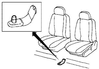
natural_image
Line drawing of a car seatbelt with a hand pointing to the seat (no text or symbols)WAI0006
Floor mat positioning aid (driver's side only)
This vehicle includes a front floor mat bracket to act as a floor mat positioning aid. NISSAN floor mats have been specially designed for your vehicle model. The driver's side floor mat has a grommet hole incorporated in it. Position the mat by placing the floor mat bracket hook through the floor mat grommet hole while centering the mat in the footwell.
Periodically check to make certain the mats are properly positioned.
SEAT BELTS
The seat belts can be cleaned by wiping them with a sponge dampened in a mild soap solution. Allow the belts to dry completely in the shade before using them. See “Seat belt maintenance” in the “Safety – Seats, seat belts and supplemental restraint system” section of this manual.

WARNING
Do not allow wet seat belts to roll up in the retractor. NEVER use bleach, dye or chemical solvents to clean the seat belts, since these materials may severely weaken the seat belt webbing.
CORROSION PROTECTION
MOST COMMON FACTORS CONTRIBUTING TO VEHICLE CORROSION
- The accumulation of moisture-retaining dirt and debris in body panel sections, cavities, and other areas.
- Damage to paint and other protective coatings caused by gravel and stone chips or minor traffic accidents.
ENVIRONMENTAL FACTORS INFLUENCE THE RATE OF CORROSION
Moisture
Accumulation of sand, dirt and water on the vehicle body underside can accelerate corrosion. Wet floor coverings will not dry completely inside the vehicle, and should be removed for drying to avoid floor panel corrosion.
Relative humidity
Corrosion will be accelerated in areas of high relative humidity, especially those areas where the temperatures stay above freezing and where atmospheric pollution exists and road salt is used.
Temperature
High temperatures accelerate the rate of corrosion to those parts which are not well ventilated.
Air pollution
Industrial pollution, the presence of salt in the air in coastal areas, or heavy road salt use accelerates the corrosion process. Road salt also accelerates the disintegration of paint surfaces.
TO PROTECT YOUR VEHICLE FROM CORROSION
- Wash and wax your vehicle often to keep the vehicle clean.
● Always check for minor damage to the paint and repair it as soon as possible. - Keep drain holes at the bottom of the doors open to avoid water accumulation.
- Check the underbody for accumulation of sand, dirt or salt. If present, wash with water as soon as possible.
CAUTION
- NEVER remove dirt, sand or other debris from the passenger compartment by washing it out with a hose. Remove dirt with a vacuum cleaner or broom.
- Never allow water or other liquids to come in contact with electronic components inside the vehicle as this may damage them.
Chemicals used for road surface de-icing are extremely corrosive. They accelerate corrosion and deterioration of underbody components such as the exhaust system, fuel and brake lines, brake cables, floor pan and fenders.
In winter, the underbody must be cleaned periodically.
For additional protection against rust and corrosion, which may be required in some areas, consult a NISSAN dealer.
MEMO
8 Maintenance and do-it-yourself
Maintenance requirements....8-2
General maintenance 8-2
Explanation of general maintenance items ..... 8-2
Maintenance precautions....8-5
Engine compartment check locations 8-6
Engine cooling system 8-7
Checking engine coolant level 8-7
Changing engine coolant....8-8
Engine oil....8-8
Checking engine oil level 8-8
Changing engine oil 8-9
Changing engine oil filter....8-10
5-speed automatic transmission fluid 8-11
Power steering fluid....8-11
Brake fluid....8-11
Brake fluid....8-12
Window washer fluid 8-12
Window washer fluid reservoir 8-12
Battery 8-13
Jump starting 8-14
Drive belts....8-14
Spark plugs....8-15
Replacing spark plugs 8-15
Air cleaner....8-16
In-cabin microfilter....8-16
Windshield wiper blades 8-17
Cleaning 8-17
Replacing 8-18
Parking brake and brake pedal 8-20
Checking parking brake 8-20
Checking brake pedal....8-20
Brake booster....8-21
Fuses 8-21
Engine compartment....8-22
Passenger compartment 8-23
Battery replacement 8-24
Lights....8-25
Headlights....8-25
Fog lights (if so equipped)....8-26
Exterior and interior lights....8-27
Wheels and tires 8-31
Tire pressure....8-31
Tire labeling....8-35
Types of tires....8-38
Tire chains....8-38
Changing wheels and tires 8-39
MAINTENANCE REQUIREMENTS
Your new NISSAN has been designed to have minimum maintenance requirements with longer service intervals to save you both time and money. However, some day-to-day and regular maintenance is essential to maintain your NISSAN's good mechanical condition, as well as its emission and engine performance.
It is the owner's responsibility to make sure that the scheduled maintenance, as well as general maintenance, is performed.
As the vehicle owner, you are the only one who can ensure that your vehicle receives proper maintenance. You are a vital link in the maintenance chain.
Scheduled maintenance
For your convenience, both required and optional scheduled maintenance items are described and listed in your “NISSAN Service and Maintenance Guide.” You must refer to that guide to ensure that necessary maintenance is performed on your NISSAN at regular intervals.
General maintenance
General maintenance includes those items which should be checked during normal day-to-day operation. They are essential for proper vehicle operation. It is your responsibility to perform these maintenance procedures regularly as prescribed.
8-2 Maintenance and do-it-yourself
Performing general maintenance checks requires minimal mechanical skill and only a few general automotive tools.
These checks or inspections can be done by you, a qualified technician, or, if you prefer, a NISSAN dealer.
Where to go for service
If maintenance service is required or your vehicle appears to malfunction, have the systems checked and corrected by a NISSAN dealer.
NISSAN technicians are well-trained specialists who are kept up-to-date with the latest service information through technical bulletins, service tips, and in-dealership training programs. They are completely qualified to work on NISSAN vehicles before they work on your vehicle, rather than after they have worked on it.
You can be confident that a NISSAN dealer's service department performs the best job to meet the maintenance requirements on your vehicle — in a reliable and economic way.
GENERAL MAINTENANCE
During the normal day-to-day operation of the vehicle, general maintenance should be performed regularly as prescribed in this section. If you detect any unusual sounds, vibrations or smells, be sure to check for the cause or have a NISSAN dealer do it promptly. In addition, you should notify a NISSAN dealer if you think that repairs are required.
When performing any checks or maintenance work, closely observe the “Maintenance precautions” later in this section.
EXPLANATION OF GENERAL MAINTENANCE ITEMS
Additional information on the following items with “*” is found later in this section.
Outside the vehicle
The maintenance items listed here should be performed from time to time, unless otherwise specified.
Doors and engine hood Check that the doors and engine hood operate properly. Also ensure that all latches lock securely. Lubricate hinges, latches, latch pins, rollers and links as necessary. Make sure that the secondary latch keeps the hood from opening when the primary latch is released.
When driving in areas using road salt or other corrosive materials, check lubrication frequently.
Lights* Clean the headlights on a regular basis. Make sure that the headlights, stop lights, tail lights, turn signal lights, and other lights are all operating properly and installed securely. Also check headlight aim.
Road wheel nuts* When checking the tires, make sure no wheel nuts are missing, and check for any loose wheel nuts. Tighten if necessary.
Tire rotation* Tires should be rotated every 7,500 miles (12,000 km).
Tires* Check the pressure with a gauge often and always prior to long distance trips. If necessary, adjust the pressure in all tires, including the spare, to the pressure specified. Check carefully for damage, cuts or excessive wear.
Wheel alignment and balance If the vehicle should pull to either side while driving on a straight and level road, or if you detect uneven or abnormal tire wear, there may be a need for wheel alignment. If the steering wheel or seat vibrates at normal highway speeds, wheel balancing may be needed.
- For additional information regarding tires, refer to “Important Tire Safety Information” (US) or “Tire Safety Information” (Canada) in the Warranty Information Booklet.
Windshield Clean the windshield on a regular basis. Check the windshield at least every six months for cracks or other damage. Have a damaged windshield repaired by a qualified repair facility.
Windshield wiper blades* Check for cracks or wear if they do not wipe properly.
Inside the vehicle
The maintenance items listed here should be checked on a regular basis, such as when performing periodic maintenance, cleaning the vehicle, etc.
Additional information on the following items with an “*” is found later in this section.
Accelerator pedal Check the pedal for smooth operation and make sure the pedal does not bind or require uneven effort. Keep the floor mat away from the pedal.
Automatic transmission P (Park) position mechanism On a fairly steep hill check that your vehicle is held securely with the selector lever in the P (Park) position without applying any brakes.
Brake pedal and booster* Check the pedal for smooth operation and make sure it has the proper distance under it when depressed fully. Check the brake booster function. Be certain to keep the floor mat away from the pedal.
Brakes Check that the brakes do not pull the vehicle to one side when applied.
Parking brake* Check that the lever has the proper travel and confirm that your vehicle is held securely on a fairly steep hill with only the parking brake applied.
Seats Check seat position controls such as seat adjusters, seatback recliner, etc. to ensure they operate smoothly and all latches lock securely in every position. Check that the head restraints move up and down smoothly and the locks (if so equipped) hold securely in all latched positions.
Seat belts Check that all parts of the seat belt system (for example, buckles, anchors, adjusters and retractors) operate properly and smoothly, and are installed securely. Check the belt webbing for cuts, fraying, wear or damage.
Steering wheel Check for changes in the steering system, such as excessive freeplay, hard steering or strange noises.
Warning lights and chimes Make sure all warning lights and chimes are operating properly.
Windshield wiper and washer* Check that the wipers and washer operate properly and that the wipers do not streak.
Windshield defroster Check that the air comes out of the defroster outlets properly and in sufficient quantity when operating the heater or air conditioner.
Under the hood and vehicle
The maintenance items listed here should be checked periodically (for example, each time you check the engine oil or refuel).
Battery* Check the fluid level in each cell. It should be between the MAX and MIN lines. Vehicles operated in high temperatures or under severe conditions require frequent checks of the battery fluid level.
Brake fluid levels* Make sure that the brake fluid level is between the MIN and MAX lines on the reservoir.
Engine coolant level* Check the coolant level when the engine is cold.
Engine drive belts* Make sure the drive belts are not frayed, worn, cracked or oily.
Engine oil level* Check the level after parking the vehicle on a level surface with the engine off. Wait more than 10 minutes for the oil to drain back into the oil pan.
Exhaust system Make sure there are no loose supports, cracks or holes. If the sound of the exhaust seems unusual or there is a smell of exhaust fumes, immediately have the exhaust system inspected by a NISSAN dealer. See the carbon monoxide warning in the “Starting and driving” section of this manual.
Fluid leaks Check under the vehicle for fuel, oil, water or other fluid leaks after the vehicle has been parked for a while. Water dripping from the air conditioner after use is normal. If you should notice any leaks or if gasoline fumes are evident, check for the cause and have it corrected immediately.
Power steering fluid level* and lines Check the level when the fluid is cold, with the engine off. Check the lines for proper attachment, leaks, cracks, etc.
Radiator and hoses Check the front of the radiator and clean off any dirt, insects, leaves, etc., that may have accumulated. Make sure the hoses have no cracks, deformation, rot or loose connections.
Underbody The underbody is frequently exposed to corrosive substances such as those used on icy roads or to control dust. It is very important to remove these substances from the underbody, otherwise rust may form on the floor pan, frame, fuel lines and exhaust system. At the end of winter, the underbody should be thoroughly flushed with plain water, in those areas where mud and dirt may have accumulated. See the “Appearance and care” section of this manual.
Windshield washer fluid* Check that there is adequate fluid in the reservoir.
8-4 Maintenance and do-it-yourself
MAINTENANCE PRECAUTIONS
When performing any inspection or maintenance work on your vehicle, always take care to prevent serious accidental injury to yourself or damage to the vehicle. The following are general precautions which should be closely observed.

WARNING
- Park the vehicle on a level surface, apply the parking brake securely and block the wheels to prevent the vehicle from moving. Move the shift selector lever to P (Park).
- Be sure the ignition key is in the OFF or LOCK position when performing any parts replacement or repairs.
- Never leave the engine or automatic transmission related component harnesses disconnected while the ignition switch is in the ON position.
- Never connect or disconnect the battery or any transistorized component while the ignition switch is in the ON position.
-
Your vehicle is equipped with an automatic engine cooling fan. It may come on at any time without warning, even if the ignition key is in the OFF position and the engine is not running. To avoid injury, always disconnect the negative battery cable before working near the fan.
-
If you must work with the engine running, keep your hands, clothing, hair and tools away from moving fans, belts and any other moving parts.
- It is advisable to secure or remove any loose clothing and remove any jewelry, such as rings, watches, etc. before working on your vehicle.
- Always wear eye protection whenever you work on your vehicle.
- If you must run the engine in an enclosed space such as a garage, be sure there is proper ventilation for exhaust gases to escape.
- Never get under the vehicle while it is supported only by a jack. If it is necessary to work under the vehicle, support it with safety stands.
- Keep smoking materials, flame and sparks away from the fuel tank and battery.
- On gasoline engine models with the multiport fuel injection (MFI) system, the fuel filter or fuel lines should be serviced by a NISSAN dealer because the fuel lines are under high pressure even when the engine is off.

CAUTION
- Do not work under the hood while the engine is hot. Turn the engine off and wait until it cools down.
- Avoid contact with used engine oil and coolant. Improperly disposed engine oil, engine coolant and/or other vehicle fluids can damage the environment. Always conform to local regulations for disposal of vehicle fluid.
This “Maintenance and do-it-yourself” section gives instructions regarding only those items which are relatively easy for an owner to perform.
A genuine NISSAN service manual is also available. See “Owner’s Manual/Service Manual order information” in the “Technical and consumer information” section of this manual.
You should be aware that incomplete or improper servicing may result in operating difficulties or excessive emissions, and could affect warranty coverage. If in doubt about any servicing, have it done by a NISSAN dealer.
ENGINE COMPARTMENT CHECK LOCATIONS
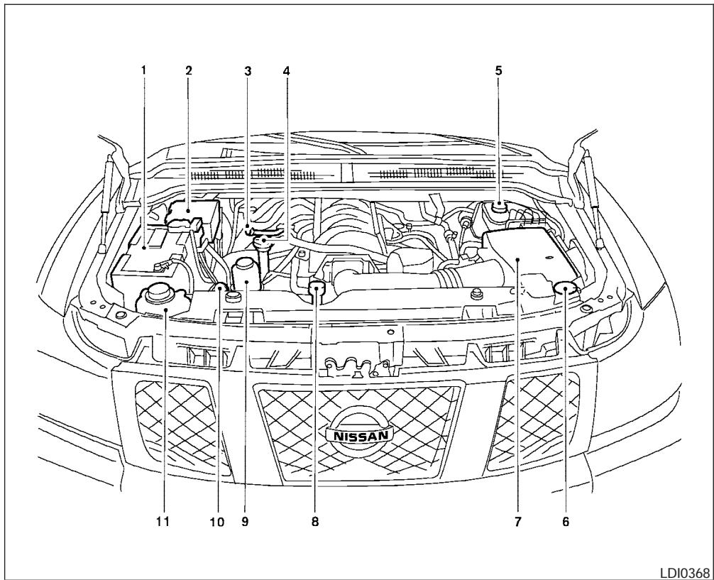
- Battery
- Fuse/fusible link box
- Transmission dipstick
- Engine oil filler cap
- Brake fluid reservoir
- Windshield washer fluid reservoir
- Air cleaner
- Radiator cap
- Power steering fluid reservoir
- Engine oil dipstick
- Engine coolant reservoir
NOTE:
Engine cover removed for clarity.
ENGINE COOLING SYSTEM
The engine cooling system is filled at the factory with Genuine NISSAN Long Life Antifreeze/Coolant to provide year-round anti-freeze and coolant protection. The anti-freeze solution contains rust and corrosion inhibitors. Additional engine cooling system additives are not necessary.

WARNING
- Never remove the radiator or coolant reservoir cap when the engine is hot. Wait until the engine and radiator cool down. Serious burns could be caused by high pressure fluid escaping from the radiator. See precautions in "If your vehicle overheats" found in the "In case of emergency" section of this manual.
- The radiator is equipped with a pressure type radiator cap. To prevent engine damage, use only a genuine NISSAN radiator cap.
| Outside temperature down to | Genuine NISSAN Long Life Antifreeze/ Coolant or equivalent | Demineral- ized or dis- tilled water | |
| °C | °F | ||
| -35 | -30 | 50% | 50% |

CAUTION
When adding or replacing coolant, be sure to use only a Genuine NISSAN Long Life Antifreeze/Coolant (green) or equivalent with the proper mixture ratio of 50% antifreeze and 50% demineralized or distilled water. The use of other types of coolant solutions or coolant colors, such as orange, may damage the engine cooling system.
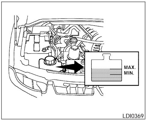
CHECKING ENGINE COOLANT LEVEL
Check the coolant level in the reservoir when the engine is cold. If the coolant level is below the MIN level, add coolant to the MAX level. If the reservoir is empty, check the coolant level in the radiator when the engine is cold. If there is insufficient coolant in the radiator, fill the radiator with coolant up to the filler opening and also add it to the reservoir up to the MAX level.
The engine coolant reservoir is a pressurized tank. When installing the cap, tighten it until a clicking sound is heard.
ENGINE OIL
If the cooling system frequently requires coolant, have it checked by a NISSAN dealer.
CHANGING ENGINE COOLANT
A NISSAN dealer can change the engine coolant. The service procedure can be found in the NISSAN Service Manual.
Improper servicing can result in reduced heater performance and engine overheating.

WARNING
- To avoid the danger of being scalded, never change the coolant when the engine is hot.
- Never remove the radiator or engine coolant reservoir cap when the engine is hot. Serious burns could be caused by high pressure fluid escaping from the radiator.
- Avoid direct skin contact with used coolant. If skin contact is made, wash thoroughly with soap or hand cleaner as soon as possible.
- Keep coolant out of the reach of children and pets.
Engine coolant must be disposed of properly. Check your local regulations.
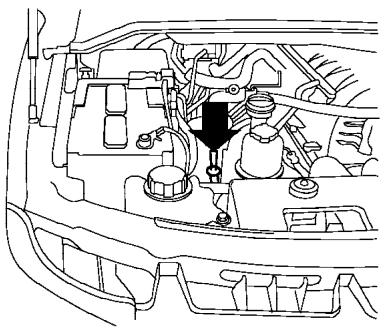
natural_image
Technical line drawing of a car engine bay with internal components and a black arrow indicating a component (no text or symbols present)LDI0370
CHECKING ENGINE OIL LEVEL
- Park the vehicle on a level surface and apply the parking brake.
- Start the engine and let it idle until it reaches operating temperature.
- Turn off the engine. Wait more than 10 minutes for the oil to drain back into the oil pan.
- Remove the dipstick and wipe it clean. Re-insert it all the way.
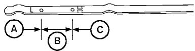
flowchart
graph LR
    A["A"] --> B["B"]
    B --> C["C"]
LDI0371
-
Remove the dipstick again and check the oil level. It should be between the H (High) and L (Low) marks Ⓑ. This is the normal operating oil level range. If the oil level is below the L (Low) mark Ⓐ, remove the oil filler cap and pour recommended oil through the opening. Do not overfill Ⓓ.
-
Recheck oil level with the dipstick.
It is normal to add some oil between oil maintenance intervals or during the break-in period, depending on the severity of operating conditions.

CAUTION
Oil level should be checked regularly. Operating the engine with an insufficient amount of oil can damage the engine, and such damage is not covered by warranty.
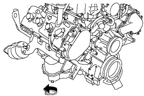
natural_image
Technical line drawing of an internal combustion engine (no text or labels)LDI0372
CHANGING ENGINE OIL
- Park the vehicle on a level surface and apply the parking brake.
- Start the engine and let it idle until it reaches operating temperature, then turn it off.
- Remove the oil filler cap by turning it counterclockwise.
- Place a large drain pan under the drain plug.
- Remove the drain plug with a wrench by turning it counterclockwise and completely drain the oil.
If the oil filter is to be changed, remove and replace it at this time. See “Changing engine oil filter” later in this section.

WARNING
- Prolonged and repeated contact with used engine oil may cause skin cancer.
- Try to avoid direct skin contact with used oil. If skin contact is made, wash thoroughly with soap or hand cleaner as soon as possible.
- Keep used engine oil out of reach of children.

CAUTION
Be careful not to burn yourself. The engine oil may be hot.
- Waste oil must be disposed of properly.
- Check your local regulations.
- Clean and reinstall the drain plug and a new washer. Securely tighten the drain plug with a wrench. Do not use excessive force.
Drain plug tightening torque: 22 - 29 ft-lb (29 - 39 N·m)
- Refill engine with recommended oil through the oil filler opening, then install the oil filler cap securely.
See “Capacities and recommended fuel/lubricants” in the “Technical and consumer information” section of this manual for drain and refill capacity.
The drain and refill capacity depends on the oil temperature and drain time. Use these specifications for reference only. Always use the dipstick to determine when the proper amount of oil is in the engine.
- Start the engine. Check for leakage around the drain plug and oil filter. Correct as required.
- Turn the engine off and wait more than 10 minutes. Check the oil level with the dipstick. Add engine oil if necessary.
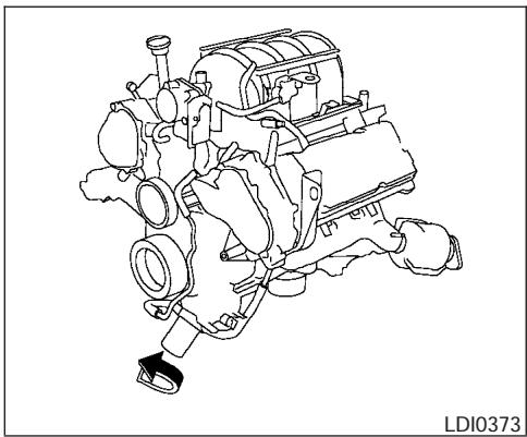
natural_image
Technical line drawing of an internal combustion engine assembly (no text or symbols)CHANGING ENGINE OIL FILTER
- Park the vehicle on a level surface and apply the parking brake.
- Turn the engine off.
- Place a large drain pan under the oil filter.
- Loosen the oil filter with an oil filter wrench by turning it counterclockwise. Then remove the oil filter by turning it by hand.

CAUTION
Be careful not to burn yourself. The engine oil may be hot.
- Wipe the engine oil filter mounting surface with a clean rag.
Be sure to remove any old gasket material remaining on the mounting surface of the engine. - Coat the gasket on the new filter with clean engine oil.
- Screw on the oil filter until a slight resistance is felt, then tighten an additional 2/3 turn.
- Start the engine and check for leakage around the oil filter. Correct as required.
- Turn the engine off and wait more than 10 minutes. Check the oil level. Add engine oil if necessary.
When checking or replacement is required, we recommend your NISSAN dealer for servicing.

WARNING
- Use only Genuine Matic J ATF. Do not mix with other fluids.
- Using automatic transmission fluid other than Genuine Matic J ATF will cause deterioration in driveability and automatic transmission durability, and may damage the automatic transmission, which is not covered by the NISSAN new vehicle limited warranty.
The specified automatic transmission fluid is also described on caution labels located in the engine compartment.
POWER STEERING FLUID
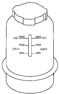
WDI0256
The fluid level should be checked using the HOT MAX range on the power steering fluid reservoir at fluid temperatures of 122irc - 176ircF ( 50irc - 80ircC ) or using the COLD MAX range on the power steering fluid reservoir at fluid temperatures of 32irc - 86ircF ( 0irc - 30ircC ).
If the fluid is below the MIN line, add Genuine NISSAN PSF. Remove the cap and fill through the opening.

CAUTION
• DO NOT OVERFILL.
- Recommended fluid is Genuine NISSAN PSF or equivalent.
BRAKE FLUID
For further brake fluid specification information, refer to “Capacities and recommended fuel/lubricants” in the “Technical and consumer information” section of this manual.

WARNING
Use only new fluid from a sealed container. Old, inferior or contaminated fluid may damage the brake system. The use of improper fluids can damage the brake system and affect the vehicle's stopping ability.

CAUTION
Do not spill the fluid on any painted surfaces. This will damage the paint. If fluid is spilled, immediately wash the surface with water.
WINDOW WASHER FLUID
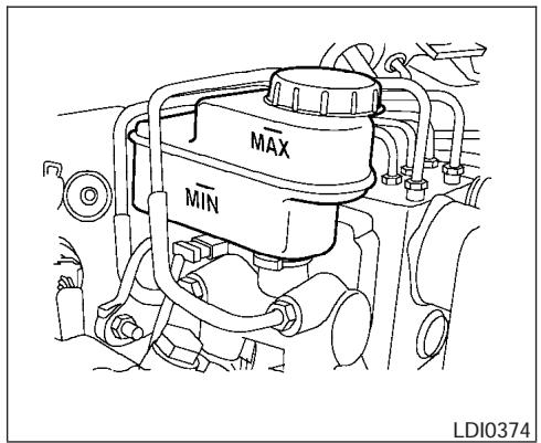
BRAKE FLUID
Check the brake fluid level in the reservoir. If the fluid level is below the MIN line or the brake warning light comes on, add Genuine NISSAN Super Heavy Duty Brake Fluid or equivalent DOT 3 fluid up to the MAX line. If fluid must be added frequently, the system should be checked by a NISSAN dealer.
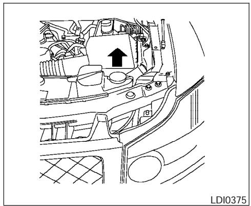
natural_image
Line drawing of a car interior showing engine compartment with an upward arrow indicating motion (no text or symbols)WINDOW WASHER FLUID RESERVOIR
Fill the window washer fluid reservoir periodically. Add window washer fluid when the low window washer fluid warning light comes on.
To fill the window washer fluid reservoir, lift the cap off the reservoir tank and pour the window washer fluid into the tank opening.
Add a washer solvent to the washer for better cleaning. In the winter season, add a windshield washer antifreeze. Follow the manufacturer's instructions for the mixture ratio.
Refill the reservoir more frequently when driving conditions require an increased amount of window washer fluid.
Recommended fluid is Genuine NISSAN Windshield Washer Concentrate Cleaner & Anti-freeze or equivalent.
CAUTION
- Do not substitute engine anti-freeze coolant for window washer solution. This may result in damage to the paint.
- Do not fill the window washer reservoir tank with washer fluid concentrates at full strength. Some methyl alcohol based washer fluid concentrates may permanently stain the grille if spilled while filling the window washer reservoir tank.
- Pre-mix washer fluid concentrates with water to the manufacturer's recommended levels before pouring the fluid into the window washer reservoir tank. Do not use the window washer reservoir tank to mix the washer fluid concentrate and water.
BATTERY
- Keep the battery surface clean and dry. Any corrosion should be washed off with a solution of baking soda and water.
- Make certain the terminal connections are clean and securely tightened.
- If the vehicle is not to be used for 30 days or longer, disconnect the negative (-) battery terminal cable to prevent discharge.

WARNING
- Do not expose the battery to flames or electrical sparks. Hydrogen gas generated by the battery is explosive. Do not allow battery fluid to contact your skin, eyes, fabrics or painted surfaces. After touching a battery or battery cap, do not touch or rub your eyes. Thoroughly wash your hands. If the acid contacts your eyes, skin or clothing, immediately flush with water for at least 15 minutes and seek medical attention.
-
Do not operate the vehicle if the fluid in the battery is low. Low battery fluid can cause a higher load on the battery which can generate heat, reduce battery life, and in some cases lead to an explosion.
-
When working on or near a battery, always wear suitable eye protection and remove all jewelry.
- Battery posts, terminals and related accessories contain lead and lead compounds. Wash hands after handling.
- Keep battery out of the reach of children.
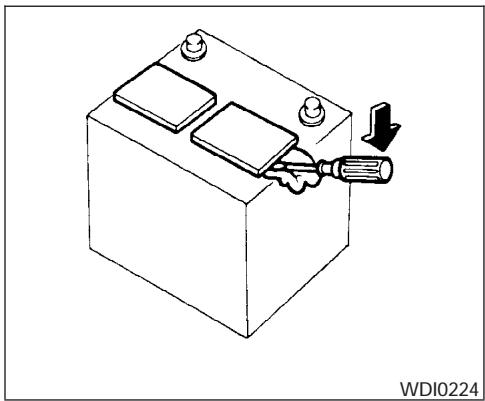
natural_image
Line drawing of a battery with a screwdriver inserted, showing internal components and a downward arrow (no text or symbols)- Remove the battery caps with a screwdriver as shown. Use a cloth to protect the battery case.
DRIVE BELTS
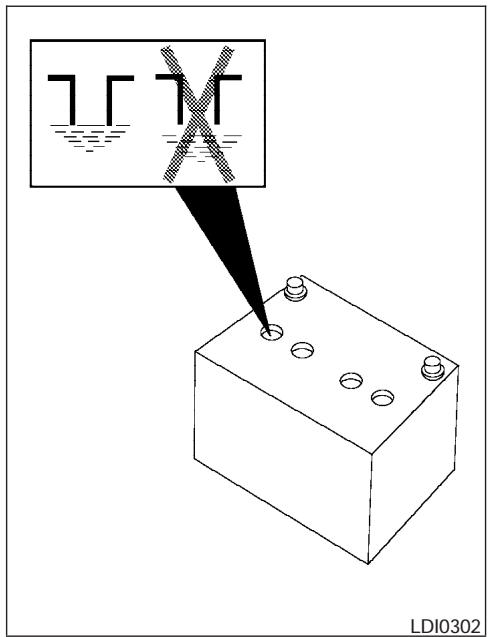
- Check the fluid level in each cell If it is necessary to add fluid, add only distilled water to bring the level up to the bottom of the filler opening. Do not overfill.
Vehicles operated in high temperatures or under severe conditions require frequent checks of the battery fluid level.
JUMP STARTING
If jump starting is necessary, see "Jump starting" in the "In case of emergency" section of this manual. If the engine does not start by jump starting, the battery may have to be replaced. Contact a NISSAN dealer.
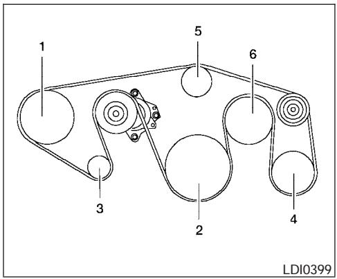
- Power steering fluid pump
- Crankshaft
- Generator
- Air conditioner
- Water pump
- Cooling fan

WARNING
Be sure the ignition key is in the OFF or LOCK position. The engine could rotate unexpectedly.
SPARK PLUGS
- Visually inspect each belt for signs of unusual wear, cuts, fraying or looseness. If the belt is in poor condition or is loose, have it replaced or adjusted by a NISSAN dealer.
- Have the belts checked regularly for condition and tension in accordance with the maintenance schedule found in the "NISSAN Service and Maintenance Guide".
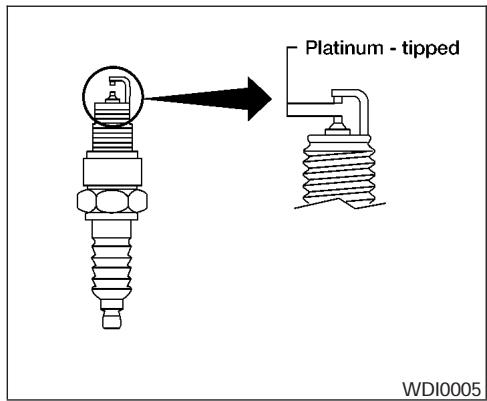
REPLACING SPARK PLUGS
Platinum-tipped spark plugs
It is not necessary to replace platinum-tipped spark plugs as frequently as conventional type spark plugs because they last much longer. Follow the maintenance log shown in the “NISSAN Service and Maintenance Guide”. Do not service platinum-tipped spark plugs by cleaning or regapping.
- Always replace spark plugs with recommended or equivalent ones.
WARNING
Be sure the engine and ignition switch are off and that the parking brake is engaged securely.
CAUTION
Be sure to use the correct socket to remove the spark plugs. An incorrect socket can damage the spark plugs.
If replacement is required, please see your NISSAN dealer for assistance.
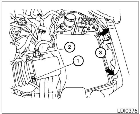
The air cleaner filter should not be cleaned and reused. Replace it according to the maintenance log shown in the “NISSAN Service and Maintenance Guide.” When replacing the filter, wipe the inside of the air cleaner filter housing and the cover with a damp cloth.
To remove the air cleaner filter:
① Loosen the screw.
② Disconnect the electrical connector.
③ Unlatch the clips and remove the air cleaner cover. Remove the air cleaner filter.
WARNING
- Operating the engine with the air cleaner removed can cause you or others to be burned. The air cleaner not only cleans the air, it stops the flame if the engine backfires. If it isn't there, and the engine backfires, you could be burned. Do not drive with the air cleaner removed, and be careful when working on the engine with the air cleaner removed.
- Never pour fuel into the throttle body or attempt to start the engine with the air cleaner removed. Doing so could result in serious injury.
IN-CABIN MICROFILTER
The in-cabin microfilter restricts the entry of airborne dust and pollen particles and reduces some objectionable outside odors. The filter is located behind the glove box. Refer to the "NISSAN Service and Maintenance Guide" for change intervals.
To replace the filter, perform the following procedure:
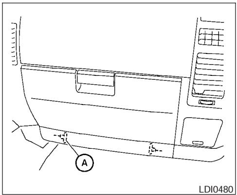
- Remove the 2 lower glove box hinge pins Ⓐ. Remove the glove box from the opening and let it hang by the cord.
WINDSHIELD WIPER BLADES
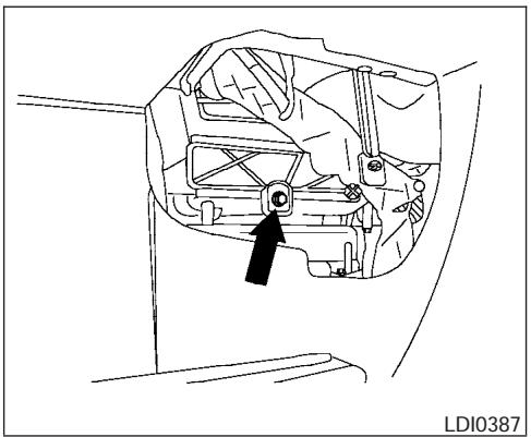
natural_image
Technical line drawing of a mechanical component with an arrow pointing to a specific part (no text or symbols present)- Remove the filter cover bolt and remove the filter cover.
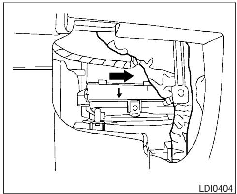
natural_image
Technical diagram of a mechanical assembly with internal components and directional arrows (no text or symbols)NOTE:
The filters are marked with air flow arrows. The end of the filter with the arrow should face the rear of the vehicle. The arrows should face downward.
- Insert the first filter into the housing and slide it over to the right. Insert the second filter into the housing.
- Replace the filter cover.
- Install the glove box door.
- Fill out the date information on the small replacement label and attach it to the glove box lid.
CLEANING
If your windshield is not clear after using the windshield washer or if a wiper blade chatters when running, wax or other material may be on the blade or windshield.
Clean the outside of the windshield with a washer solution or a mild detergent. Your windshield is clean if beads do not form when rinsing with clear water.
Clean each blade by wiping it with a cloth soaked in a washer solution or a mild detergent. Then rinse the blades with clear water. If your windshield is still not clear after cleaning the blades and using the wiper, replace the blades.

CAUTION
Worn windshield wiper blades can damage the windshield and impair driver vision.
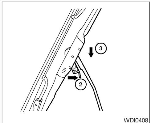
REPLACING
Replace the wiper blades if they are worn.
- Lift the wiper arm away from the windshield.
② Push the release tab, then move the wiper blade down the wiper arm to remove.
③ Remove the wiper blade. - Insert the new wiper blade onto the wiper arm until it clicks into place.
- Rotate wiper blade so the dimple is in the groove.
CAUTION
- After wiper blade replacement, return the wiper arm to its original position; otherwise it may be damaged when the hood is opened.
- Make sure the wiper blades contact the glass; otherwise the arms may be damaged from wind pressure.
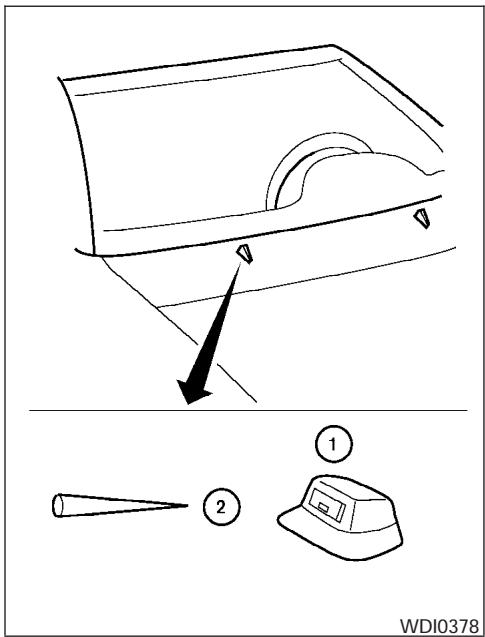
If you wax the surface of the hood, be careful not to let wax get into the washer nozzle ①. This may cause clogging or improper windshield washer operation. If wax gets into the nozzle, remove it with a needle or small pin ②.
①
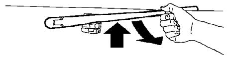
natural_image
Illustration of a hand holding a pen or tool with an upward arrow indicating motion (no text or symbols)②
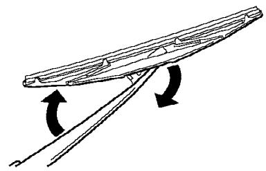
natural_image
Simple line drawing of a boat hull with two curved arrows indicating direction (no text or symbols)③
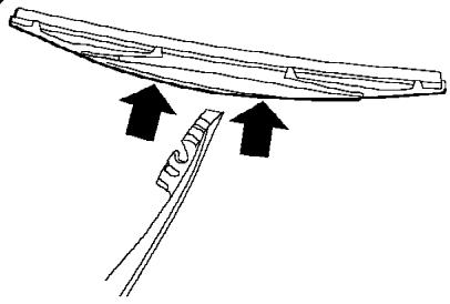
natural_image
Simple line drawing of a curved object with two arrows pointing to a textured surface and a separate vertical line (no text or symbols)LDI0379
Rear window wiper blade
① Lift the wiper arm away from the rear window.
② Push the wiper blade in and pivot until the blade becomes free.
③ Insert a new blade onto the wiper arm and snap into place.
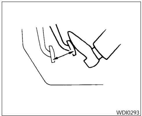
natural_image
Line drawing of a mechanical component with arrows indicating motion (no text or symbols)From the released position, firmly push the parking brake down. If the number of clicks is out of the range listed, see a NISSAN dealer.
- 3–4 clicks under depressing force of 44.1 lb (196 N).
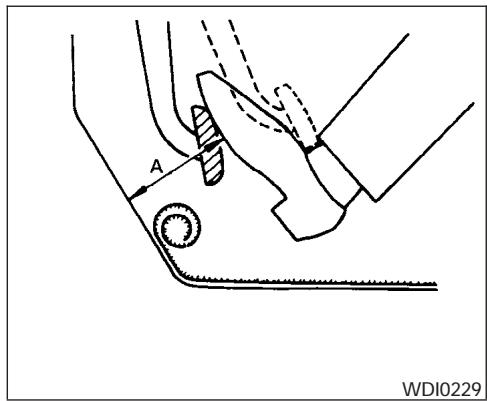
natural_image
Technical line drawing of a mechanical component with labeled point A and reference number WDI0229 (no text or symbols beyond labels)CHECKING BRAKE PEDAL
With the engine running, check the distance A between the upper surface of the pedal and the metal floor. If it is out of the range shown, see a NISSAN dealer.
Distance A: Under depression force of 110 lb (490 N)
3 1/2 in (90 mm) or more
Self-adjusting brakes
Your vehicle is equipped with self-adjusting brakes.
The front and rear disc-type brakes self-adjust every time the brake pedal is applied.

WARNING
See a NISSAN dealer for a brake system check if the brake pedal height does not return to normal.
Brake pad wear indicators
The disc brake pads on your vehicle have audible wear indicators. When a brake pad requires replacement, a high pitched scraping or screeching sound will be heard when the vehicle is in motion. The noise will be heard whether or not the brake pedal is depressed. Have the brakes checked as soon as possible if the wear indicator sound is heard.
Under some driving or climate conditions, occasional brake squeak, squeal or other noise may be heard. Occasional brake noise during light to moderate stops is normal and does not affect the function or performance of the brake system.
Proper brake inspection intervals should be followed. For more information regarding brake inspections, see the appropriate maintenance schedule information in the “NISSAN Service and Maintenance Guide”.
FUSES
BRAKE BOOSTER
Check the brake booster function as follows:
- With the engine off, press and release the brake pedal several times. When brake pedal movement (distance of travel) remains the same from one pedal application to the next, continue on to the next step.
- While depressing the brake pedal, start the engine. The pedal height should drop a little.
- With the brake pedal depressed, stop the engine. Keep the pedal depressed for about 30 seconds. The pedal height should not change.
- Run the engine for one minute without depressing the brake pedal, then turn it off. Depress the brake pedal several times. The pedal travel distance will decrease gradually with each depression as the vacuum is released from the booster.
If the brakes do not operate properly, have the brakes checked by a NISSAN dealer.
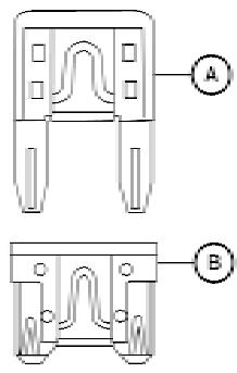
LDI0455
Two types of fuses are used. Type A is used in the fuse boxes in the engine compartment. Type B is used in the passenger compartment fuse box.
Type A fuses are provided as spare fuses. They are stored in the passenger compartment fuse box.
Type A fuses can be installed in the engine compartment and passenger compartment fuse boxes.
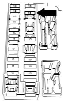
LDI0457
If a type A fuse is used to replace a type B fuse, the type A fuse will not be level with the fuse pocket as shown in the illustration. This will not affect the performance of the fuse. Make sure the fuse is installed in the fuse box securely.
Type B fuses cannot be installed in the underhood fuse boxes. Only use type A fuses in the underhood fuse boxes.
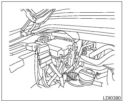
natural_image
Technical line drawing of an automotive engine bay with hoses and wiring (no text or symbols)ENGINE COMPARTMENT

CAUTION
Never use a fuse of a higher or lower amperage rating than specified on the fuse box cover. This could damage the electrical system or cause a fire.
If any electrical equipment does not come on, check for an open fuse.
- Be sure the ignition switch and the headlight switch are OFF.
-
Open the engine hood.
-
Remove the fuse box cover by pushing the tab and lifting the cover up.
- Remove the fuse with the fuse puller. The fuse puller is located in the center of the fuse block in the passenger compartment.
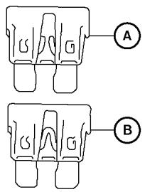
WDI0452
Type A
- If the fuse is open Ⓐ, replace it with a new fuse Ⓑ.
- If a new fuse also opens, have the electrical system checked and repaired by a NISSAN dealer.
8-22 Maintenance and do-it-yourself
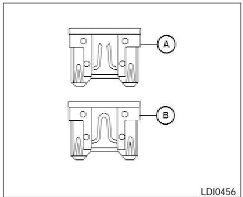
Type B
Fusible links
If the electrical equipment does not operate and fuses are in good condition, check the fusible links. If any of these fusible links are melted, replace with only genuine NISSAN parts.
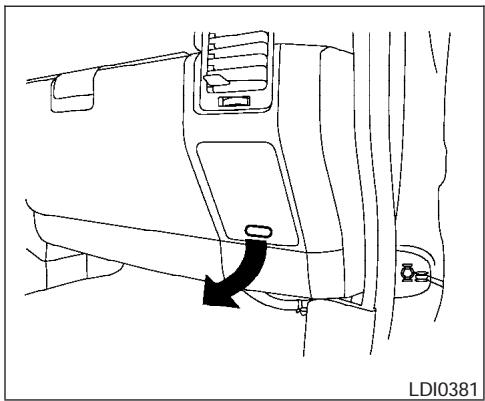
natural_image
Technical line drawing of a vehicle door panel with a black arrow indicating a component (no text or symbols present)PASSENGER COMPARTMENT

CAUTION
Never use a fuse of a higher or lower amperage rating than specified on the fuse box cover. This could damage the electrical system or cause a fire.
If any electrical equipment does not operate, check for an open fuse.
- Be sure the ignition switch and the headlight switch are OFF.
- Pull the fuse box cover to remove.
- Remove the fuse with the fuse puller.
BATTERY REPLACEMENT
- If the fuse is open, replace it with a known good fuse.
- Push the fuse box cover to install.
- If a new fuse also opens, have the electrical system checked and repaired by a NISSAN dealer.
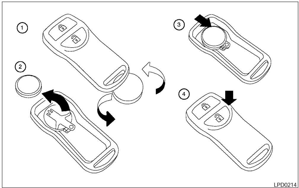
flowchart
graph TD
    A["Step 1: Initial state"] --> B["Step 2: Rotation arrow"]
    B --> C["Step 3: Rotation arrow"]
    C --> D["Step 4: Adjustment arrow"]
Replace the battery in the keyfob as follows:
① Open the lid using a coin.
② Remove the battery.
③ Install a new battery with the “+” facing down.
Recommended battery: CR2025 or equivalent.
④ Close the lid securely.
- Press the 🔊 button, then the 🔊 button two or three times to check the key-fob operation.
LIGHTS
If the battery is removed for any reason other than replacement, perform step 5.
- An improperly disposed battery can hurt the environment. Always confirm local regulations for battery disposal.
- The keyfob is water-resistant; however, if it does get wet, immediately wipe completely dry.
- The operational range of the keyfob extends to approximately 33 ft (10 m) from the vehicle. This range may vary with conditions.
FCC Notice:
Changes or modifications not expressly approved by the manufacturer for compliance could void the user's authority to operate the equipment.
This device complies with Part 15 of the FCC Rules and RSS-210 of Industry Canada.
Operation is subject to the following two conditions: (1) This device may not cause harmful interference, and (2) this device must accept any interference received, including interference that may cause undesired operation of the device.
HEADLIGHTS
Replacing the halogen headlight bulb
The headlight is a semi-sealed beam type which uses a replaceable headlight (halogen) bulb. Because the headlight assembly must be removed from the vehicle for bulb replacement, see your NISSAN dealer.
CAUTION
- High pressure halogen gas is sealed inside the halogen bulb. The bulb may break if the glass envelope is scratched or the bulb is dropped.
- When handling the bulb, do not touch the glass envelope.
• DO NOT TOUCH THE BULB
- Use the same number and wattage as originally installed:
Low beam:
Wattage: 51
Bulb no.: 9006*
High beam:
Wattage: 60
Bulb no.: 9005*
*: Always check with the Parts Department at a NISSAN dealer for the latest parts information.
- Do not leave the bulb out of the headlight reflector for a long period of time as dust, moisture and smoke may enter the headlight body and affect the performance of the headlight.
- Aiming is not necessary after replacing the bulb. When aiming adjustment is necessary, contact a NISSAN dealer.
FOG LIGHTS (if so equipped)
Replacing the fog light bulb

CAUTION
- High pressure halogen gas is sealed inside the halogen bulb. The bulb may break if the glass envelope is scratched or the bulb is dropped.
- When handling the bulb, do not touch the glass envelope.
- Use the same number and wattage as originally installed:
Wattage 37.5 Bulb No. 899*
*: Always check with the Parts Department at a NISSAN dealer for the latest parts information.
- Do not leave the bulb out of the fog light for a long period of time as dust, moisture and smoke may enter the fog light body and affect the performance of the fog light.
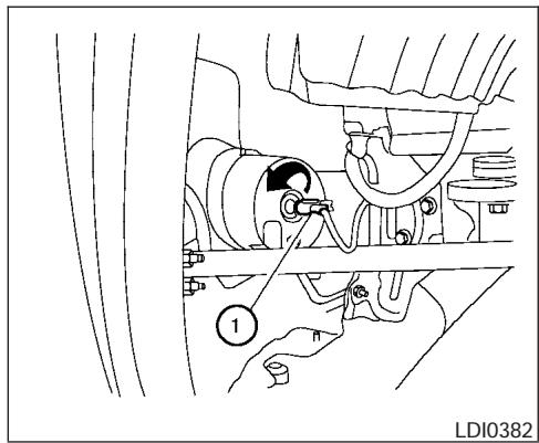
- Disconnect the negative (-) battery cable.
- The fog light is accessible in front of the front tire and behind the bumper.
- Disconnect the bulb connector ①.
- Rotate the bulb counterclockwise and remove.
- Remove by pulling it straight out of the fog light assembly. Do not shake or rotate the bulb when removing it. Do not touch the glass envelope.
- Install in the reverse order of removal.
NOTE:
To adjust the fog light vertical aim: Access the aiming screw from underneath the front bumper. The aiming screw is located on the bottom of the fog light housing. Turn the screw clockwise to raise the pattern. Turn the screw counterclockwise to lower the pattern.
EXTERIOR AND INTERIOR LIGHTS
| Item | Wattage (W) | Bulb No. |
| Headlight assembly | ||
| High | 60 | HB3/9005 |
| Low | 51 | HB4/9006 |
| Park/Turn | 8/27 | 3157AK |
| Sidemarker | 3.8 | 194 |
| Front fog light | 27 | 881 |
| Puddle lamp | 13 | 906 |
| Room/map lights | 8 | - |
| Personal lights | 5 | 2GL T2P |
| Footwell | 3.4 | 158 |
| Glove box light | 3.4 | 158 |
| Vanity mirror light | 1.8 | - |
| Step light | 3.8 | 194 |
| Cargo light | 8 | 28 |
| High-mounted stop light* | - | - |
| Rear combination light | ||
| Tail/Stop | 7/27 | 3157K |
| Backup (reversing) | 18 | 921 |
| Turn | 27 | 3156K |
| License plate light | 5 | 168 |
* See a NISSAN dealer for replacement.
Always check with the Parts Department at a NISSAN dealer for the latest parts information.
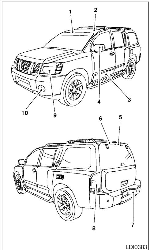
- Room/map light
- Front personal lights
- Step light
- Puddle lamp
- High-mount stoplight
- Cargo light
- License plate light
- Rear combination light
- Headlight assembly
- Fog light
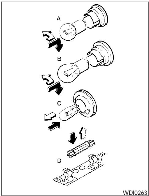
Replacement procedures
All other lights are either type A, B, C or D. When replacing a bulb, first remove the lens, lamp and/or cover.

Indicates bulb removal
Indicates bulb installation
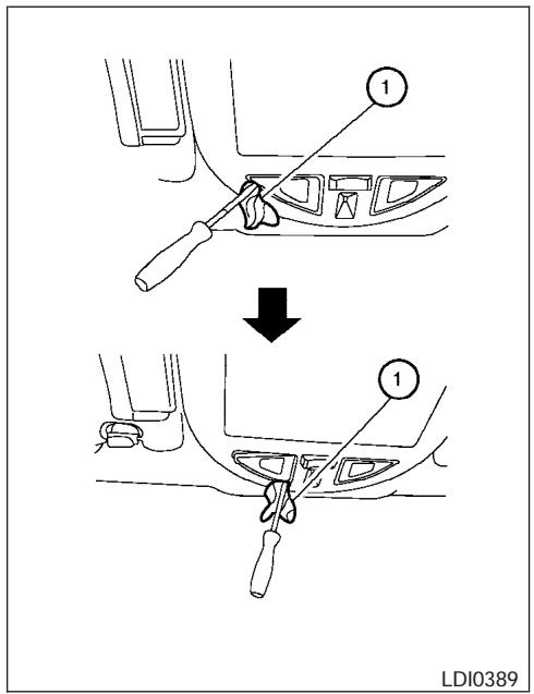
Room/map lights
Use a cloth ① to protect the housing.
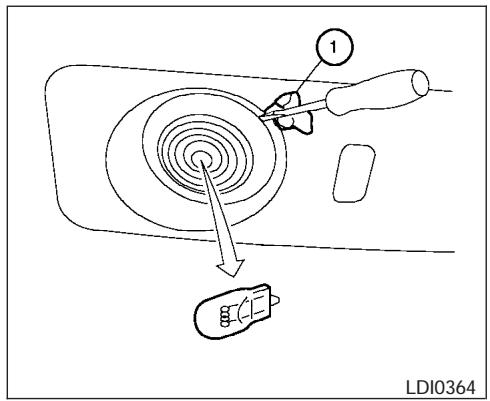
Personal lights – Type A
Use a cloth ① to protect the housing.
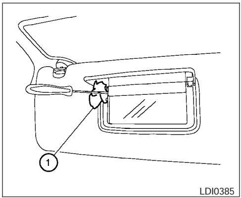
Vanity mirror
Use a cloth ① to protect the housing.
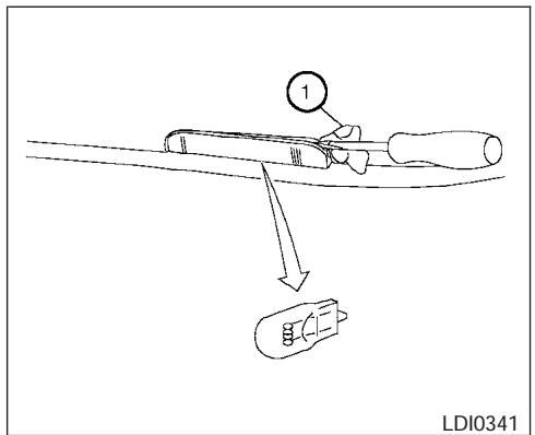
Step light
Use a cloth ① to protect the housing.
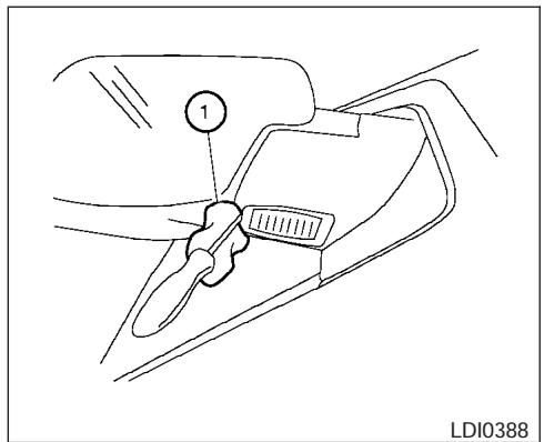
Puddle light
Use a cloth ① to protect the housing.
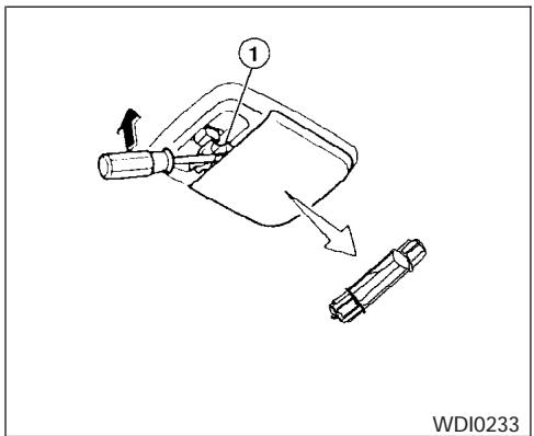
Cargo light
Use a cloth ① to protect the housing.
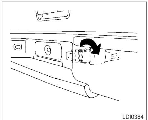
natural_image
Technical line drawing of a vehicle interior showing a mechanical component and directional arrow (no text or symbols)License plate light
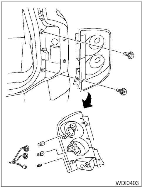
Rear combination light
WHEELS AND TIRES
If you have a flat tire, see the "In case of emergency" section of this manual.
TIRE PRESSURE
Tire inflation pressure
Check the tire pressures (including the spare) often and always prior to long distance trips. The recommended tire pressure specifications are shown on the FMVSS label or the Tire and Loading Information label (if so equipped) under the "Recommended Cold Tire Inflation Pressure" heading. The Tire and Loading Information label is affixed to the driver side center pillar. Tire pressures should be checked regularly because:
- Most tires naturally lose air over time.
- Tires can lose air suddenly when driven over potholes or other objects or if the vehicle strikes a curb while parking.
The tire pressures should be checked when the tires are cold. The tires are considered COLD after the vehicle has been parked for 3 or more hours, or driven less than 1 mile (1.6 km) at moderate speeds.
Incorrect tire pressure, including under inflation, may adversely affect tire life and vehicle handling.
WARNING
- Improperly inflated tires can fail suddenly and cause an accident.
- The Gross Maximum Weight rating is located on the FMVSS label. The vehicle weight capacity is indicated on the Tire and Loading Information label (if so equipped). Do not load your vehicle beyond this capacity. Overloading your vehicle may result in reduced tire life, unsafe operating conditions due to premature tire failure, or unfavorable handling characteristics and could also lead to a serious accident. Loading beyond the specified capacity may also result in failure of other vehicle components.
- Before taking a long trip, or whenever you heavily load your vehicle, use a tire pressure gauge to ensure that the tire pressures are at the specified level.
- Do not drive your vehicle over 85 MPH (137 km/h) unless it is equipped with high speed rated tires. Driving faster than 85 MPH (137 km/h) may result in tire failure, loss of control and possible injury.
- For additional information regarding tires, refer to “Important Tire Safety Information” (US) or “Tire Safety Information” (Canada) in the Warranty Information Booklet.
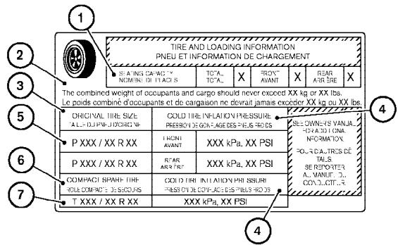
LDI0392
Type A
Tire and loading information label (for US) (if so equipped)
① Seating capacity: The maximum number of occupants that should be seated in the vehicle.
② Vehicle load limit: See loading information in the Technical and consumer information section.
③ Original tire size: The size of the tires originally installed on the vehicle at the factory.
④ Recommended cold tire inflation pressure: Inflate the tires to this pressure when the tires are cold. Tires are considered COLD after the vehicle has been parked for 3 or more hours, or driven less than 1 mile (1.6 km) at moderate speeds. The recommended cold tire inflation is set by the manufacturer to provide the best balance of tire wear and vehicle handling characteristics based on the vehicles GVWR.
⑤ Tire size – refer to “Tire labeling” later in this section.
⑥ and ⑦ Spare tire size or compact spare tire size (if so equipped).
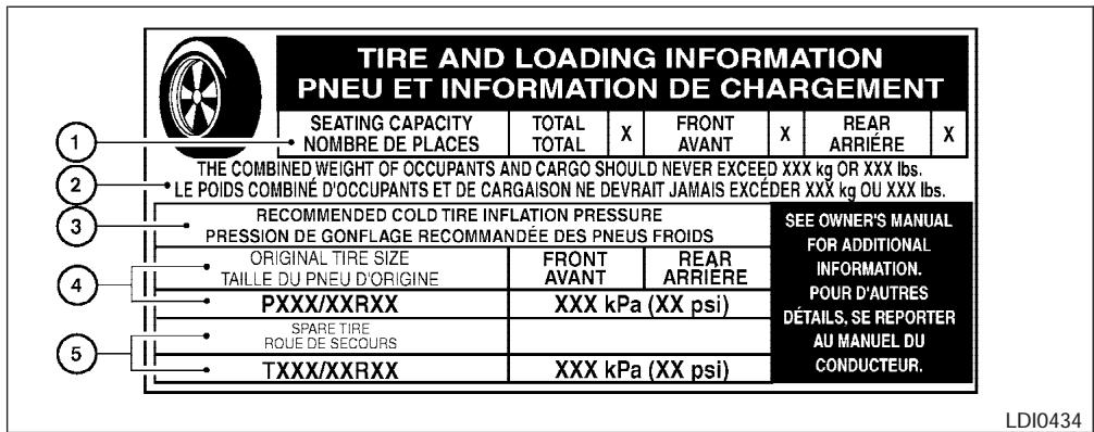
Type B
Tire and loading information label (for US)
① Seating capacity: The maximum number of occupants that should be seated in the vehicle.
② Vehicle load limit: See loading information in the Technical and consumer information section.
③ Recommended cold tire inflation pressure: Inflate the tires to this pressure when the tires are cold. Tires are considered COLD after the vehicle has been parked for 3 or more hours, or driven less than 1 mile (1.6 km) at moderate speeds. The recommended cold tire inflation is set by the manufacturer to provide the best balance of tire wear and vehicle handling characteristics based on the vehicles GVWR.
④ Original tire size: The size of the tires originally installed on the vehicle at the factory.
⑤ Spare tire size or compact spare tire size (if so equipped).
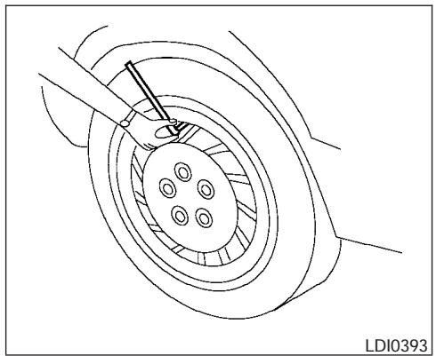
natural_image
Technical line drawing of a mechanical assembly with a central bearing and surrounding components (no text or symbols)Checking tire pressure
- Remove the valve stem cap from the tire.
- Press the pressure gauge squarely onto the valve stem. Do not press too hard or force the valve stem sideways, or air will escape. If the hissing of air escaping from the tire is heard while checking the pressure, reposition the gauge to eliminate this leakage.
- Remove the gauge.
-
Read the tire pressure on the gauge stem and compare to the specification shown on the Tire and Loading Information label.
-
Add air to the tire as needed. If too much air is added, press the core of the valve stem briefly with the tip of the gauge stem to release pressure. Recheck the pressure and add or release air as needed.
- Install the valve stem cap.
- Check the pressure of all other tires, including the spare.
| Size | Cold Tire Inflation Pressure | |
| FrontOriginal Tire | P285/70R17P265/70R18 | 240 kPa, 35 PSI |
| RearOriginal Tire | P285/70R17P265/70R18 | 240 kPa, 35 PSI |
| Spare Tire | P285/70R17P265/70R18 | 240 kPa, 35 PSI |
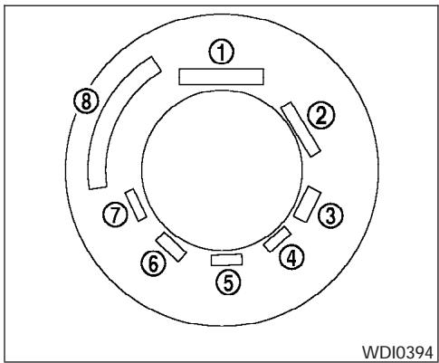
TIRE LABELING
Federal law requires tire manufacturers to place standardized information on the sidewall of all tires. This information identifies and describes the fundamental characteristics of the tire and also provides the tire identification number (TIN) for safety standard certification. The TIN can be used to identify the tire in case of a recall.
P215/65R15 95H

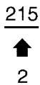


WDI0395
① Tire size (example: P215/65R15 95H)
- P: The "P" indicates the tire is designed for passenger vehicles.
- Three-digit number: This number gives the width in millimeters of the tire from sidewall edge to sidewall edge.
- Two-digit number: This number, known as the aspect ratio, gives the tire's ratio of height to width.
- R: The "R" stands for radial.
-
Two-digit number: This number is the wheel or rim diameter in inches.
-
Two- or three-digit number: This number is the tire's load index. It is a measurement of how much weight each tire can support. You may not find this information on all tires because it is not required by law.
- Tire speed rating. You should not drive the vehicle faster than the tire speed rating.
DOT XX XX XXX XXXX


WDI0396
② TIN (Tire Identification Number) for a new tire (example: DOT XX XX XXX XXXX)
- DOT: Abbreviation for the "Department Of Transportation." The symbol can be placed above, below or to the left or right of Tire Identification Number.
- Two-digit code: Manufacturer's identification mark
- Two-digit code: Tire size
- Three-digit code: Tire type code (Optional)
-
Three-digit code: Date of Manufacture
-
Four numbers represent the week and year the tire was built. For example, the numbers 3103 means the 31st week of 2003. If these numbers are missing, then look on the other sidewall of the tire.
③ Tire ply composition and material
The number of layers or plies of rubber-coated fabric in the tire. Tire manufacturers also must indicate the materials in the tire, which include steel, nylon, polyester, and others.
④ Maximum permissible inflation pressure
This number is the greatest amount of air pressure that should be put in the tire. Do not exceed the maximum permissible inflation pressure.
⑤ Maximum load rating
This number indicates the maximum load in kilograms and pounds that can be carried by the tire. When replacing the tires on the vehicle, always use a tire that has the same load rating as the factory installed tire.
⑥ Term of "tubeless" or "tube type"
Indicates whether the tire requires an inner tube (“tube type”) or not (“tubeless”).
⑦ The word "radial"
The word "radial" is shown if the tire has radial structure.
⑧ Manufacturer or brand name
Manufacturer or brand name is shown.
Other Tire-related Terminology
In addition to the many terms that are defined throughout this section, Intended Outboard Sidewall is (1) the sidewall that contains a whitewall, bears white lettering or bears manufacturer, brand, and/or model name molding that is higher or deeper than the same molding on the other sidewall of the tire, or (2) the outward facing sidewall of an asymmetrical tire that has a particular side that must always face outward when mounted on a vehicle.
TYPES OF TIRES
WARNING
- When changing or replacing tires, be sure all four tires are of the same type (i.e., Summer, All Season or Snow) and construction. A NISSAN dealer may be able to help you with information about tire type, size, speed rating and availability.
- Replacement tires may have a lower speed rating than the factory equipped tires, and may not match the potential maximum vehicle speed. Never exceed the maximum speed rating of the tire.
- For additional information regarding tires, refer to "Important Tire Safety Information" (US) or "Tire Safety Information" (Canada) in the Warranty Information Booklet.
All season tires
NISSAN specifies All Season tires on some models to provide good performance all year, including snowy and icy road conditions. All Season tires are identified by ALL SEASON and/or M&S on the tire sidewall. Snow tires have better snow traction than All Season tires and may be more appropriate in some areas.
Summer tires
NISSAN specifies summer tires on some models to provide superior performance on dry roads. Summer tire performance is substantially reduced in snow and ice. Summer tires do not have the tire traction rating "M&S" on the tire sidewall.
If you plan to operate your vehicle in snowy or icy conditions, NISSAN recommends the use of SNOW tires or ALL SEASON tires on all four wheels.
Snow tires
If snow tires are needed, it is necessary to select tires equivalent in size and load rating to the original equipment tires. If you do not, it can adversely affect the safety and handling of your vehicle.
Generally, snow tires have lower speed ratings than factory equipped tires and may not match the potential maximum vehicle speed. Never exceed the maximum speed rating of the tire.
If you install snow tires, they must be the same size, brand, construction and tread pattern on all four wheels.
For additional traction on icy roads, studded tires may be used. However, some U.S. states and Canadian provinces prohibit their use. Check local, state and provincial laws before installing
studded tires. Skid and traction capabilities of studded snow tires on wet or dry surfaces may be poorer than that of non-studded snow tires.
TIRE CHAINS
Use of tire chains may be prohibited according to location. Check the local laws before installing tire chains. When installing tire chains, make sure they are the proper size for the tires on your vehicle and are installed according to the chain manufacturer's suggestions. Use only SAE class "S" chains. Class "S" chains are used on vehicles with restricted tire to vehicle clearance. Vehicles that can use Class "S" chains are designed to meet the minimum clearances between the tire and the closest vehicle suspension or body component required to accommodate the use of a winter traction device (tire chains or cables). The minimum clearances are determined using the factory equipped tire size. Other types may damage your vehicle. Use chain tensioners when recommended by the tire chain manufacturer to ensure a tight fit. Loose end links of the tire chain must be secured or removed to prevent the possibility of whipping action damage to the fenders or underbody. If possible, avoid fully loading your vehicle when using tire chains. In addition, drive at a reduced speed. Otherwise, your vehicle may be damaged and/or vehicle handling and performance may be adversely affected.
Tire chains must be installed only on the rear wheels and not on the front wheels.
Do not use tire chains on dry roads. Driving with chains in such conditions can cause damage to the various mechanisms of the vehicle due to some overstress.
Use only the 2WD range when driving on clear paved roads.
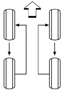
flowchart
graph TD
    A["Stage 1"] --> B["Stage 2"]
    B --> C["Stage 3"]
    C --> D["Stage 4"]
    D --> A
    style A fill:#f9f,stroke:#333
    style B fill:#f9f,stroke:#333
    style C fill:#f9f,stroke:#333
    style D fill:#f9f,stroke:#333
WDI0258
CHANGING WHEELS AND TIRES
Tire rotation
NISSAN recommends rotating the tires every 7,500 miles (12,000 km).
See “Flat tire” in the “In case of emergency” section in this manual for tire replacing procedures.
As soon as possible, tighten the wheel nuts to the specified torque with a torque wrench.
Wheel nut tightening torque:
98 ft-lb (133 N·m)
The wheel nuts must be kept tightened to specifications at all times. It is recommended that wheel nuts be tightened to specification at each tire rotation interval.

WARNING
- After rotating the tires, check and adjust the tire pressure.
- Retighten the wheel nuts when the vehicle has been driven for 600 miles (1,000 km) (also in cases of a flat tire, etc.).
- Do not include the spare tire in the tire rotation.
- For additional information regarding tires, refer to “Important Tire Safety Information” (US) or “Tire Safety Information” (Canada) in the Warranty Information Booklet.
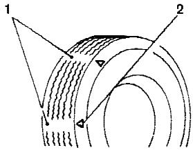
WDI0259
- Wear indicator
- Location mark
Tire wear and damage
WARNING
- Tires should be periodically inspected for wear, cracking, bulging or objects caught in the tread. If excessive wear, cracks, bulging or deep cuts are found, the tire(s) should be replaced.
- The original tires have built-in tread wear indicators. When the wear indicators are visible, the tire(s) should be replaced.
- Improper service of the spare tire may result in serious personal injury. If it is necessary to repair the spare tire, contact a NISSAN dealer.
- For additional information regarding tires, refer to “Important Tire Safety Information” (US) or “Tire Safety Information” (Canada) in the Warranty Information Booklet.
Replacing wheels and tires
When replacing a tire, use the same size, tread design, speed rating and load carrying capacity as originally equipped. Recommended types and sizes are shown in “Wheels and tires” in the “Technical and consumer information” section of this manual.
WARNING
- The use of tires other than those recommended or the mixed use of tires of different brands, construction (bias, bias-belted or radial), or tread patterns can adversely affect the ride, braking, handling, ground clearance, body-to-tire clearance, tire chain clearance, speedometer calibration, headlight aim and bumper height. Some of these effects may lead to accidents and could result in serious personal injury.
-
If the wheels are changed for any reason, always replace with wheels which have the same off-set dimension. Wheels of a different off-set could cause premature tire wear, degrade vehicle handling characteristics and/or interference with the brake discs/drums. Such interference can lead to decreased braking efficiency and/or early brake pad/shoe wear. Refer to “Wheels and tires” in the “Technical and consumer information” section of this manual for wheel off-set dimensions.
-
When a spare tire is mounted or a wheel is replaced, tire pressure will not be indicated and the low tire pressure warning system will not function. Contact your NISSAN dealer as soon as possible for tire replacement and/or system resetting.
- Do not install a deformed wheel or tire even if it has been repaired. Such wheels or tires could have structural damage and could fail without warning.
- The use of retread tires is not recommended.
- For additional information regarding tires, refer to "Important Tire Safety Information" (US) or "Tire Safety Information" (Canada) in the Warranty Information Booklet.
Wheel balance
Unbalanced wheels may affect vehicle handling and tire life. Even with regular use, wheels can get out of balance. Therefore, they should be balanced as required.
Wheel balance service should be performed with the wheels off the vehicle. Spin balancing the wheels on the vehicle could lead to mechanical damage.
- For additional information regarding tires, refer to "Important Tire Safety Information" (US) or "Tire Safety Information" (Canada) in the Warranty Information Booklet.
Care of wheels
- Wash the wheels when washing the vehicle to maintain their appearance.
- Clean the inner side of the wheels when the wheel is changed or the underside of the vehicle is washed.
- Do not use abrasive cleaners when washing the wheels.
- Inspect wheel rims regularly for dents or corrosion. Such damage may cause loss of pressure or poor seal at the tire bead.
- NISSAN recommends waxing the road wheels to protect against road salt in areas where it is used during winter.
MEMO
9 Technical and consumer information
Capacities and recommended fuel/lubricants ..... 9-2
Fuel recommendation 9-3
Engine oil and oil filter recommendation ..... 9-4
Recommended SAE viscosity number 9-5
Air conditioner system refrigerant and lubricant recommendations 9-6
Specifications....9-7
Engine 9-7
Wheels and tires 9-8
Dimensions and weights 9-8
When traveling or registering your vehicle in another country 9-9
Vehicle identification 9-9
Vehicle identification number (VIN) plate ..... 9-9
Vehicle identification number (chassis number) 9-9
Engine serial number....9-10
F.M.V.S.S. certification label 9-10
Emission control information label 9-10
Tire and loading information label....9-11
Air conditioner specification label....9-11
Installing front license plate....9-11
Vehicle loading information 9-12
Terms 9-12
Vehicle load capacity 9-12
Securing the load....9-14
Loading tips 9-14
Measurement of weights 9-15
Towing a trailer....9-15
Maximum load limits 9-15
Towing load/specification chart 9-17
Towing safety 9-17
Flat towing....9-24
Snow plow 9-24
Uniform tire quality grading 9-25
Emission control system warranty 9-26
Reporting safety defects (US only) 9-26
Readiness for inspection/maintenance (I/M) test .....9-26
Event data recorders....9-27
Owner's Manual/Service Manual order information ...9-28
In the event of a collision 9-29
CAPACITIES AND RECOMMENDED FUEL/LUBRICANTS
The following are approximate capacities. The actual refill capacities may be a little different. When refilling, follow the procedure described in the “Maintenance and do-it-yourself” section to determine the proper refill capacity.
| Capacity (Approximate) | Recommended Fluids and Lubricants | ||||
| US measure | Imp measure | Liter | |||
| Fuel | 28 gal | 23-1/4 gal | 105.8 | Unleaded gasoline with an octane rating of at least 87 AKI (RON 91)*1 | |
| Engine oil *7Drain and Refill | |||||
| With oil filter change | 6-1/2 qt | 5-1/2 qt | 6.2 | • API Certification Mark *2 *3• API grade SL, Energy Conserving *2 *3• ILSAC grade GF-III*2 *3 | |
| Without oil filter change | 6-1/4 qt | 5-1/4 qt | 5.9 | ||
| Cooling system | |||||
| With reservoir | 3-3/4 gal | 3-1/8 gal | 14.4 | 50% Genuine NISSAN Long Life Antifreeze/Coolant or equivalent50% Demineralized or distilled water | |
| Automatic transmission fluid | Genuine Nissan Matic J ATF *4 | ||||
| Power steering fluid (PSF) | Refill to the proper level according to the instructions inthe “Maintenance and do-it-yourself” section. | Genuine NISSAN PSF or equivalent.*8 | |||
| Brake fluid | Genuine NISSAN Super Heavy Duty Brake Fluid*5 or equivalent DOT 3 | ||||
| Multi-purpose grease | — | — | — | NLGI No. 2 (Lithium Soap base) | |
| Air conditioning system refrigerant | — | — | — | HFC-134a (R-134a)*6 | |
| Air conditioning system lubricants | — | — | — | NISSAN A/C System Lubricant Type S (DH-PS) or equivalent*6 | |
| Transfer fluid | — | — | — | Genuine Nissan Matic D ATF (Continental U.S. and Alaska) or CanadaNISSAN Automatic Transmission Fluid*8, *10 | |
| Front final drive oil | — | — | — | API GL-5 Viscosity SAE 80W-90*9, *10 | |
| Rear final drive oil | — | — | — | API GL-5 Viscosity SAE 80W-90*9, *10 | |
| Windshield washer fluid (shared betweenfront and rear wipers) | 1-1/4 gal | 1 gal | 4.5 | Genuine NISSAN Windshield Washer Concentrate Cleaner & Antifreeze orequivalent | |
*1: For further details, see "Fuel recommendation."
*2: For further details, see “Engine oil and oil filter recommendations.”
*3: For further details, see "Recommended SAE engine oil viscosity."
*4: Using automatic transmission fluid other than Genuine Nissan Matic J ATF will cause deterioration in driveability and automatic transmission durability, and may damage the automatic transmission, which is not covered by the NISSAN new vehicle warranty.
*5: Available in mainland USA through your NISSAN dealer.
*6: For further details, see "Air conditioner specification label."
*7: For further details, see "Changing engine oil."
*8: For Canada, NISSAN Automatic Transmission Fluid (ATF), DEXRON™ III/MERCON™, or equivalent ATF may also be used.
*9: For hot climates, viscosity SAE 90 is suitable for ambient temperatures above 0ircC (32°F).
*10: See your NISSAN dealer for service.
9-2 Technical and consumer information
FUEL RECOMMENDATION
Use unleaded regular gasoline with an octane rating of at least 87 AKI (Anti-Knock Index) number (Research octane number 91).

CAUTION
- Using a fuel other than that specified could adversely affect the emission control system, and may also affect the warranty coverage.
- Under no circumstances should a leaded gasoline be used, because this will damage the three-way catalyst.
Reformulated gasoline
Some fuel suppliers are now producing reformulated gasolines. These gasolines are specially designed to reduce vehicle emissions. NISSAN supports efforts towards cleaner air and suggests that you use reformulated gasoline when available.
Gasoline containing oxygenates
Some fuel suppliers sell gasoline containing oxygenates such as ethanol, MTBE and methanol with or without advertising their presence. NISSAN does not recommend the use of fuels of which the oxygenate content and the fuel compatibility for your NISSAN cannot be readily determined. If in doubt, ask your service station manager.
If you use oxygenate-blend gasoline, please take the following precautions as the usage of such fuels may cause vehicle performance problems and/or fuel system damage.
- The fuel should be unleaded and have an octane rating no lower than that recommended for unleaded gasoline.
- If an oxygenate-blend other than methanol blend is used, it should contain no more than 10% oxygenate. (MTBE may, however, be added up to 15%.)
- If a methanol blend is used, it should contain no more than 5% methanol (methyl alcohol, wood alcohol). It should also contain a suitable amount of appropriate cosolvents and corrosion inhibitors. If not properly formulated with appropriate cosolvents and corrosion inhibitors, such methanol blends may cause fuel system damage and/or vehicle performance problems. At this time, sufficient data is not available to ensure that all methanol blends are suitable for use in NISSAN vehicles.
If any driveability problems such as engine stalling and difficult hot-starting are experienced after using oxygenate-blend fuels, immediately change to a non-oxygenate fuel or a fuel with a low blend of MTBE.
Take care not to spill gasoline during refueling. Gasoline containing oxygenates can cause paint damage.
Aftermarket fuel additives
NISSAN does not recommend the use of any aftermarket fuel additives (for example, fuel injector cleaner, octane booster, intake valve deposit removers, etc.) which are sold commercially. Many of these additives intended for gum, varnish or deposit removal may contain active solvents or similar ingredients that can be harmful to the fuel system and engine.
Octane rating tips
Using unleaded gasoline with an octane rating lower than recommended can cause persistent, heavy “spark knock.” (“Spark knock” is a metallic rapping noise.) If severe, this can lead to engine damage. If you detect a persistent heavy spark knock even when using gasoline of the stated octane rating, or if you hear steady spark knock while holding a steady speed on level roads, have a NISSAN dealer correct the
condition. Failure to correct the condition is misuse of the vehicle, for which NISSAN is not responsible.
Incorrect ignition timing may result in spark knock, after-run and/or overheating, which may cause excessive fuel consumption or engine damage. If any of the above symptoms are encountered, have your vehicle checked at a NISSAN dealer.
However, now and then you may notice light spark knock for a short time while accelerating or driving up hills. This is not a cause for concern, because you get the greatest fuel benefit when there is light spark knock for a short time under heavy engine load.
API certification mark
API service symbol
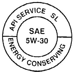
WTI0082
ENGINE OIL AND OIL FILTER RECOMMENDATION
Selecting the correct oil
It is essential to choose engine oil with the correct quality and viscosity to ensure satisfactory engine life and performance. NISSAN recommends the use of a low friction oil (energy conserving oil) in order to improve fuel economy and conserve energy. Oils which do not have the specified quality label should not be used as they could cause engine damage.
Only those engine oils with the American Petroleum Institute (API) CERTIFICATION MARK on the front of the container should be used. This type of oil supersedes the existing API SG, SH, or SJ and Energy Conserving II categories.
If you cannot find engine oil with the API CERTIFICATION MARK, use API grade SL Energy Conserving oil. An oil with a single designation SL, or in combination with other categories (for example, SL/CF) may also be used if one with the API CERTIFICATION MARK cannot be found. An ILSAC grade GF-III oil can also be used.
NISSAN recommends mineral based oils. These oils must, however, meet the API quality and SAE viscosity ratings specified for your vehicle.
Oil additives
NISSAN does not recommend the use of oil additives. The use of an oil additive is not necessary when the proper oil type is used and maintenance intervals are followed.
Oil which may contain foreign matter or has been previously used should not be used.
Oil viscosity
The engine oil viscosity or thickness changes with temperature. Because of this, it is important to select the engine oil viscosity based on the temperatures at which the vehicle will be operated before the next oil change. The chart “Recommended SAE viscosity number” shows the recommended oil viscosities for the expected ambient temperatures. Choosing an oil viscosity other than that recommended could cause serious engine damage.
Selecting the correct oil filter
Your new NISSAN vehicle is equipped with a high-quality genuine NISSAN oil filter. When replacing, use a genuine NISSAN oil filter or its equivalent for the reason described in “Change intervals”.
Change intervals
The oil and oil filter change intervals for your engine are based on the use of the specified quality oils and filters. Using engine oil and filters that are not of the specified quality, or exceeding recommended oil and filter change intervals could reduce engine life. Damage to the engine caused by improper maintenance or use of incorrect oil and filter quality and/or viscosity is not covered by the NISSAN new vehicle warranty.
Your engine was filled with a high-quality engine oil when it was built. You do not have to change the oil before the first recommended change interval. Oil and filter change intervals depend upon how you use your vehicle.
Operation under the following conditions may require more frequent oil and filter changes:
● repeated short distance driving at cold outside temperatures
● driving in dusty conditions
- extensive idling
- towing a trailer
Outside Temperature Range
Anticipated Before Next Oil Change
GASOLINE ENGINE OIL
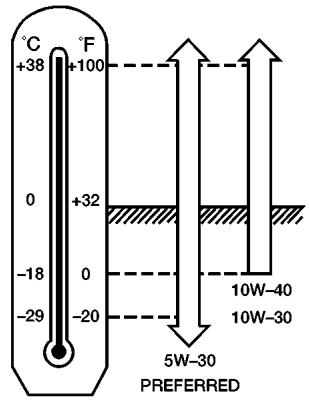
ATI1028
RECOMMENDED SAE VISCOSITY NUMBER
- SAE 5W-30 viscosity oil is preferred for all temperatures. SAE 10W-30 or SAE 10W-40 viscosity oils may be used if the ambient temperature is above 0irc F ( -18irc C).
AIR CONDITIONER SYSTEM REFRIGERANT AND LUBRICANT RECOMMENDATIONS
The air conditioner system in your NISSAN vehicle must be charged with the refrigerant HFC-134a (R-134a) and the lubricant, NISSAN A/C system oil DH-PS or the exact equivalents.

CAUTION
The use of any other refrigerant or lubricant will cause severe damage to the air conditioning system and will require the replacement of all air conditioner system components.
The refrigerant HFC-134a (R-134a) in your NISSAN vehicle does not harm the earth's ozone layer. Although this refrigerant does not affect the earth's atmosphere, certain government regulations require the recovery and recycling of any refrigerant during automotive air conditioner system service. A NISSAN dealer has the trained technicians and equipment needed to recover and recycle your air conditioner system refrigerant.
Contact a NISSAN dealer when servicing your air conditioner system.
ENGINE
| Model | VK56DE |
| Type | Gasoline, 4-cycle, DOHC |
| Cylinder arrangement | 8-cylinder, V-block, Slanted at 90° |
| Bore x Stroke | in (mm) 3.858 x 3.622 (98 x 92) |
| Displacement | cu in (cm3) 338.78 (5,552) |
| Firing order | 1-8-7-3-6-5-4-2 |
| Idle speed | |
| A/T (in “N” position) | See the “Emission Control Information label” on the under-side of the hood. |
| Ignition timing (degree B.T.D.C. at idle speed) | |
| CO % at idle | |
| Spark plug | Standard PLFR5A-11Hot PLFR4A-11Cold PLFR6A-11 |
| Spark plug gap (Nominal) | in (mm) 0.043 (1.1) |
| Camshaft operation | Timing chain |
The spark ignition system of this vehicle meets all requirements of the Canadian Interference-Causing Equipment Regulations.
WHEELS AND TIRES
| Wheels | |
| 17 x 7.5J | |
| 18 x 8.0J | |
| Tires | |
| P285/70R17 | |
| P265/70R18 | |
| Spare tire | Full size |
DIMENSIONS AND WEIGHTS
| Overall length | in (mm) | 206.9(5,255) |
| Overall width | in (mm) | 78.8(2,001) |
| Overall height | ||
| 2wd with roof rack | in (mm) | 77.8(1,977) |
| 4wd with roof rack | in (mm) | 78.7(1,998) |
| 2wd without roof rack | in (mm) | 75.7(1,922) |
| 4wd without roof rack | in (mm) | 76.5(1,944) |
| Front tread | ||
| 17 inch tire | in (mm) | 67.5(1,715) |
| 18 inch tire | in (mm) | 67.9(1,725) |
| Rear tread | ||
| 17 inch tire | in (mm) | 67.5(1,715) |
| 18 inch tire | in (mm) | 67.9(1,725) |
| Wheelbase | in (mm) | 123.2(3,130) |
| Gross vehicle weight rating | lb (kg) | See the “F.M.V.S.S. certification label” on the center pillar between the driver's side front and side doors. |
| Gross axle weight rating | ||
| Front | lb (kg) | |
| Rear | lb (kg) |
WHEN TRAVELING OR REGISTERING YOUR VEHICLE IN ANOTHER COUNTRY
When planning to drive your NISSAN vehicle in another country, you should first find out if the fuel available is suitable for your vehicle's engine.
Using fuel with an octane rating that is too low may cause engine damage. All gasoline vehicles must be operated with unleaded gasoline. Therefore, avoid taking your vehicle to areas where appropriate fuel is not available.
When transferring the registration of your vehicle to another country, state, province or district, it may be necessary to modify the vehicle to meet local laws and regulations.
The laws and regulations for motor vehicle emission control and safety standards vary according to the country, state, province or district; therefore, vehicle specifications may differ.
When any vehicle is to be taken into another country, state, province or district and registered, its modifications, transportation, and registration are the responsibility of the user. NISSAN is not responsible for any inconvenience that may result.
VEHICLE IDENTIFICATION
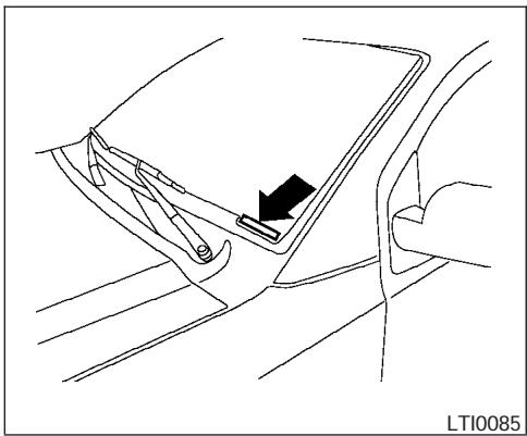
natural_image
Line drawing of a car interior showing a hand holding a clip and a black arrow pointing to the side panel (no text or symbols)VEHICLE IDENTIFICATION NUMBER (VIN) PLATE
The vehicle identification number (VIN) plate is attached as shown. This number is the identification for your vehicle and is used in the vehicle registration.
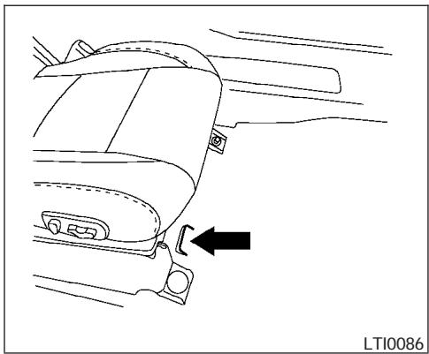
natural_image
Line drawing of a car interior showing the side arm and seat, with an arrow pointing to the wheel (no text or symbols present)VEHICLE IDENTIFICATION NUMBER (chassis number)
The vehicle identification number is located as shown.
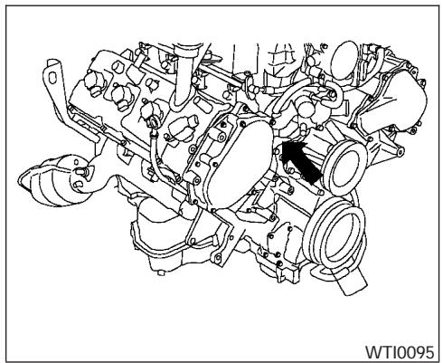
natural_image
Technical line drawing of an internal combustion engine assembly (no text or labels)ENGINE SERIAL NUMBER
The number is stamped on the engine as shown.
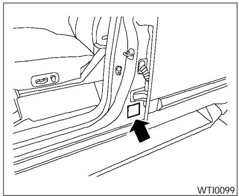
natural_image
Line drawing of a car seatbelt mechanism with a black arrow indicating the direction (no text or symbols present)F.M.V.S.S. CERTIFICATION LABEL
The Federal Motor Vehicle Safety Standard (F.M.-V.S.S.) certification label is affixed as shown. This label contains valuable vehicle information, such as: Gross Vehicle Weight Ratings (GVWR), Gross Axle Weight Rating (GAWR), month and year of manufacture, Vehicle Identification Number (VIN), etc. Review it carefully.

natural_image
Line drawing of a car rear bumper with an arrow pointing to the front panel (no text or symbols)EMISSION CONTROL INFORMATION LABEL
The emission control information label is attached as shown.
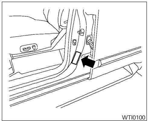
natural_image
Technical line drawing of a car interior showing a valve and seat assembly (no text or symbols)TIRE AND LOADING INFORMATION LABEL
The cold tire pressure is shown on the Tire and Loading Information label. The label is located as shown.
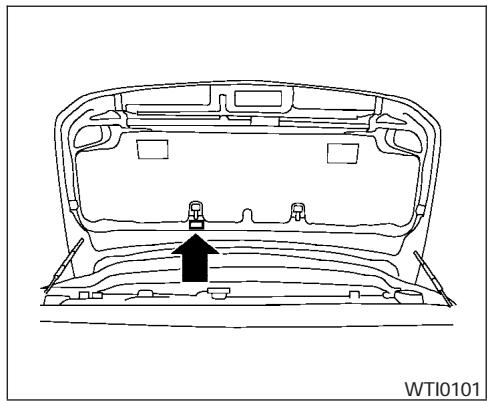
natural_image
Technical line drawing of a car back panel with an arrow indicating a component (no text or symbols present)AIR CONDITIONER SPECIFICATION LABEL
The air conditioner specification label is affixed as shown.
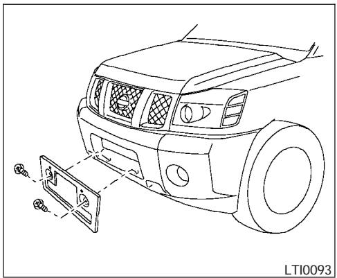
natural_image
Line drawing of a car's front bumper and dashboard assembly (no text or symbols)Use the following steps to mount the front license plate:
- Make holes on the plastic finisher at the location mark (small dimple) using a 0.20 in (5 mm) drill. Apply light pressure to the drill. Install the license plate holder using the two screws provided with the holder.
- Mount the license plate using two M6-14mm bolts.
License plate bolt tightening torque: 3.8 - 4.7 ft-lb (5.10 - 6.37 N·m)
WARNING
- It is extremely dangerous to ride in a cargo area inside a vehicle. In a collision, people riding in these areas are more likely to be seriously injured or killed.
- Do not allow people to ride in any area of your vehicle that is not equipped with seats and seat belts.
- Be sure everyone in your vehicle is in a seat and using a seat belt properly.
TERMS
It is important to familiarize yourself with the following terms before loading your vehicle:
- Curb Weight (actual weight of your vehicle) - vehicle weight including: standard and optional equipment, fluids, emergency tools, and spare tire assembly. This weight does not include passengers and cargo.
-
GVW (Gross Vehicle Weight) - curb weight plus the combined weight of passengers and cargo.
-
GVWR (Gross Vehicle Weight Rating) - maximum total combined weight of the unloaded vehicle, passengers, luggage, hitch, trailer tongue load and any other optional equipment. This information is located on the F.M.V.S.S. label.
- GAWR (Gross Axle Weight Rating) - maximum weight (load) limit specified for the front or rear axle. This information is located on the F.M.V.S.S. label.
- GCWR (Gross Combined Weight rating) - The maximum total weight rating of the vehicle, passengers, cargo, and trailer.
- Vehicle Capacity Weight, Load limit, Total load capacity - maximum total weight limit specified of the load (passengers and cargo) for the vehicle. This is the maximum combined weight of occupants and cargo that can be loaded into the vehicle. If the vehicle is used to tow a trailer, the trailer tongue weight must be included as part of the cargo load. This information is located on the Tire and Loading Information label (if so equipped).
- Cargo capacity - permissible weight of cargo, the subtracted weight of occupants from the load limit.
VEHICLE LOAD CAPACITY
Do not exceed the load limit of your vehicle shown as "The combined weight of occupants and cargo" on the Tire and Loading Information label. Do not exceed the number of occupants shown as "Seating Capacity" on Tire and Loading Information label.
To get "the combined weight of occupants and cargo", add the weight of all occupants, then add the total luggage weight. Examples are shown below.
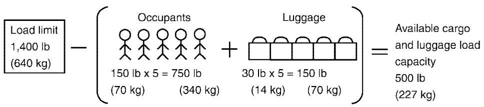
WTI0091
Steps for determining correct load limit
- Locate the statement "The combined weight of occupants and cargo should never exceed XXX pounds" on your vehicle's tire placard.
- Determine the combined weight of the driver and passengers that will be riding in your vehicle.
-
Subtract the combined weight of the driver and passengers from XXX kilograms or XXX pounds.
-
The resulting figure equals the available amount of cargo and luggage load capacity. For example, if the XXX amount equals 1400 lbs. and there will be five 150 lb. passengers in your vehicle, the amount of available cargo and luggage load capacity is 650 lbs. (1400-750 (5 * 150) = 650 lbs.)
-
Determine the combined weight of luggage and cargo being loaded on the vehicle. That weight may not safely exceed the available cargo and luggage load capacity calculated in Step 4.
-
If your vehicle will be towing a trailer, load from your trailer will be transferred to your vehicle. Consult this manual to determine how this reduces the available cargo and luggage load capacity of your vehicle.
Before driving a loaded vehicle, confirm the you do not exceed the Gross Vehicle Weight Rating (GVWR) or the Gross Axle Weight Rating (GAWR) for your vehicle. See “Measurement of Weights” later in this section.
Also check tires for proper inflation pressures. See the Tire and Loading label.
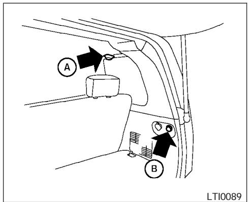
Cargo area ceiling tie-down hooks SECURING THE LOAD
There are tie down hooks located in the cargo area as shown. The tie down hooks can be used to secure cargo with ropes or other types of straps.
Do not apply a total load of more than 55 lbs. (245 N) to a single Ⓐ plastic hook or 44 lbs. (196 N) to a single Ⓑ plastic hook when securing cargo.
Do not apply a total load of more than 110 lbs. (490 N) to a single metal floor tie-down hook when securing cargo.
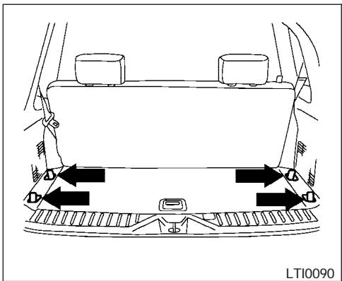
natural_image
Top-down diagram of a car's rearview and side-mounted dashboard with directional arrows indicating traffic flow (no text or symbols)Cargo area floor tie-down hooks
WARNING
- Properly secure all cargo with ropes or straps to help prevent it from sliding or shifting. Do not place cargo higher than the seatbacks. In a sudden stop or collision, unsecured cargo could cause personal injury.
- Do not load your vehicle any heavier than the GVWR or the maximum front and rear GAWRs. If you do, parts of your vehicle can break, tire damage could occur, or it can change the way your vehicle handles. This could result in loss of control and cause personal injury.
LOADING TIPS
- The GVW must not exceed GVWR or GAWR as specified on the F.M.V.S.S. certification label.
- Do not load the front and rear axle to the GAWR. Doing so will exceed the GVWR.
WARNING
- Properly secure all cargo with ropes or straps to help prevent it from sliding or shifting. Do not place cargo higher than the seatbacks. In a sudden stop or collision, unsecured cargo could cause personal injury.
TOWING A TRAILER
- Do not load your vehicle any heavier than the GVWR or the maximum front and rear GAWRs. If you do, parts of your vehicle can break, tire damage could occur, or it can change the way your vehicle handles. This could result in loss of control and cause personal injury.
- Overloading not only can shorten the life of your vehicle and the tire, but can also cause unsafe vehicle handling and longer braking distances. This may cause a premature tire failure which could result in a serious accident and personal injury. Failures caused by overloading are not covered by the vehicle's warranty.
MEASUREMENT OF WEIGHTS
Secure loose items to prevent weight shifts that could affect the balance of your vehicle. When the vehicle is loaded, drive to a scale and weigh the front and the rear wheels separately to determine axle loads. Individual axle loads should not exceed either of the gross axle weight ratings (GAWR). The total of the axle loads should not exceed the gross vehicle weight rating (GVWR). These ratings are given on the vehicle certification label. If weight ratings are exceeded, move or remove items to bring all weights below the ratings.
WARNING
Overloading or improper loading of a trailer and its cargo can adversely affect vehicle handling, braking and performance and may lead to accidents.
CAUTION
- Do not tow a trailer or haul a heavy load for the first 500 miles (800 km). Your engine, axle or other parts could be damaged.
- For the first 500 miles (800 km) that you tow a trailer, do not drive over 50 mph (80 km/h) and do not make starts at full throttle. This helps the engine and other parts of your vehicle wear in at the heavier loads.
Your new vehicle was designed to be used primarily to carry passengers and cargo. Remember that towing a trailer places additional loads on your vehicle's engine, drive train, steering, braking and other systems.
MAXIMUM LOAD LIMITS
Maximum trailer loads
Never allow the total trailer load to exceed the value specified in the following Towing Load/Specification Chart found later in this section. The total trailer load equals trailer weight plus its cargo weight.
- When towing a trailer load of 1,000 lbs. (454 kg) or more, trailers with a brake system MUST be used.
The maximum GCWR (Gross Combined Weight Rating) should not exceed the value specified in the following Towing Load/ Specification Chart.
The GCWR equals the combined weight of the towing vehicle (including passengers and cargo) plus the total trailer load. Towing loads greater than these or using improper towing equipment could adversely affect vehicle handling, braking and performance.
The ability of your vehicle to tow a trailer is not only related to the maximum trailer loads, but also the places you plan to tow. Tow weights appropriate for level highway driving may have to be reduced on very steep grades or in low traction situations (for example, on slippery boat ramps).
Temperature conditions can also affect towing. For example, towing a heavy trailer in high outside
temperatures on graded roads can affect engine performance and cause overheating. The engine protection mode, which helps reduce the chance of engine damage, could activate and automatically decrease engine power. Vehicle speed may decrease under high load. Plan your trip carefully to account for trailer and vehicle load, weather and road conditions.
WARNING
Overheating can result in reduced engine power and vehicle speed. The reduced speed may be lower than other traffic, which could increase the chance of a collision. Be especially careful when driving. Pull to the side of the road to a safe area. Allow the engine to cool and return to normal operation. See “If your vehicle overheats” in the “In case of emergency” section of this manual.
CAUTION
Vehicle damage resulting from improper towing procedures are not covered by NISSAN warranties.
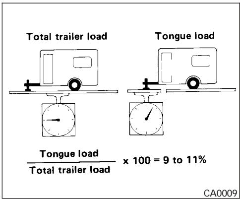
Tongue load
When using a weight carrying or a weight distributing hitch, keep the tongue load between 10 - 15 percent of the total trailer load within the maximum tongue load limits shown in the following Towing Load/Specification Chart. If the tongue load becomes excessive, rearrange cargo to allow for proper tongue load.
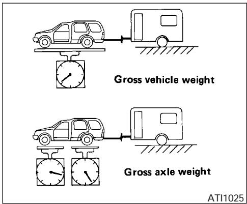
Maximum gross vehicle weight/ maximum gross axle weight
The gross vehicle weight of the towing vehicle must not exceed the gross vehicle weight rating (GVWR) shown on the F. M. V. S. S. certification label. The gross vehicle weight equals the combined weight of the unloaded vehicle, passengers, luggage, hitch, trailer tongue load and any other optional equipment. In addition, front or rear gross axle weight must not exceed the gross axle weight rating (GAWR) shown on the F. M. V. S. S. certification label.
TOWING LOAD/SPECIFICATION CHART
| US & CAN | |||
| 2WD | 4WD | ||
| Towing Capacity*1 | w/o tow package | 6,500 lb. (2,948 kg) | 6,500 lb. (2,948 kg) |
| with tow package*2 | 9,100 lb. (4,128 kg) | 9,100 lb. (4,128 kg) | |
| Tongue Load | w/o tow package | 650 lb. (295 kg) | 650 lb. (295 kg) |
| with tow package*2 | 910 lb. (413 kg) | 910 lb. (413 kg) | |
| Gross Combined Weight Rating | w/o tow package | 12,800 lb. (5,806 kg) | 13,000 lb. (5,897 kg) |
| with tow package*2 | 14,600 lb. (6,622 kg) | 14,822 lb. (6,722 kg) | |
*1: The towing capacity values are calculated assuming a base vehicle with driver and any options required to achieve the rating. Additional passengers, cargo and/or optional equipment will add weight to the vehicle and reduce your vehicle's maximum towing capacity.
*2: Requires weight distribution hitch.
TOWING SAFETY
Trailer hitch
Your vehicle may be equipped with an optional trailer tow package. The trailer tow package includes a receiver-type frame mounted hitch. This hitch is rated for the maximum towing capacity of this vehicle when the proper towing equipment is used. Choose a proper ball mount and hitch ball that is rated for the trailer to be towed. Genuine Nissan ball mounts and hitch balls are available from your NISSAN dealer.
If your vehicle is not equipped with the optional trailer tow package, check the towing capacity of your bumper hitch or receiver-type frame mounted hitch. Choose a proper hitch for your vehicle and trailer. A genuine Nissan trailer hitch is available from your NISSAN dealer. Make sure the trailer hitch is securely attached to the vehicle to help avoid personal injury or property damage due to sway caused by crosswinds, rough road surfaces or passing trucks.

WARNING
- Trailer hitch components have specific weight ratings. Your vehicle may be capable of towing a trailer heavier than the weight rating of the hitch components. Never exceed the weight rating of the hitch components. Doing so can cause serious personal injury or property damage
Hitch ball
Choose a hitch ball of the proper size and weight rating for your trailer:
- The required hitch ball size is stamped on most trailer couplers. Most hitch balls also have the size printed on the top of the ball.
- Choose the proper class hitch ball based on the trailer weight.
- The diameter of the threaded shank of the hitch ball must be matched to the ball mount hole diameter. The hitch ball shank should be no more than 1/16" smaller than the hole in the ball mount.
- The threaded shank of the hitch ball must be long enough to be properly secured to the ball mount. There should be at least 2 threads showing beyond the lock washer and nut.
Ball mount
The hitch ball is attached to the ball mount and the ball mount is inserted into the hitch receiver. Choose a proper class ball mount based on the trailer weight. Additionally, the ball mount should be chosen to keep the trailer tongue level with the ground.
Weight carrying hitches
A weight carrying or "dead weight" ball mount is one that is designed to carry the whole amount of tongue weight and gross weight directly on the ball mount and on the receiver.
Weight distribution hitch
This type of hitch is also called a “load-leveling” or “equalizing” hitch. A set of bars attach to the ball mount and to the trailer to distribute the tongue weight (hitch weight) of your trailer. Many vehicles can’t carry the full tongue weight of a given trailer, and need some of the tongue weight transferred through the frame and pushing down on the front wheels. This gives stability to the tow vehicle.
Another reason to have a weight distributing ball mount is to comply with the rating on your receiver. Most receivers have a weight carrying rating of 5,000 lbs. gross weight, 500 lbs. tongue weight and a weight distribution rating of 10,000
lbs. gross weight, 1,000 lbs. tongue weight. This means that without using a weight distributing ballmount, the receiver is only designed to carry 5,000 lbs.
When hooking up a trailer using a weight distributing hitch, always refer to the hitch manufacturer's instructions.
- Park unloaded vehicle on a level surface. With the ignition on and the doors closed, allow the vehicle to stand for several minutes so that it can level.
- Measure the height of a reference point on the front and rear bumpers at the center of the vehicle.
- Attach the trailer to the vehicle and adjust the hitch equalizers so that the front bumper height is within 0 - .5 inches (0 - 13 mm) of the reference height measured in step 2. The rear bumper should be no higher than the reference height measured in step 2.
WARNING
Properly adjust the weight distributing hitch so the rear of the bumper is no higher than the measured reference height when the trailer is attached. If the rear bumper is higher than the measured reference height when loaded, the vehicle may handle unpredictably which could cause a loss of vehicle control and cause serious personal injury or property damage.
Sway control device
Sway control devices are used to help control the effects of sudden maneuvers, wind gusts, and buffeting caused by other vehicles. Make sure the sway control device is compatible with the trailer's brake system.
Class I hitch
Class I trailer hitch equipment (receiver, ball mount and hitch ball) can be used to tow trailers of a maximum weight of 2,000 lb (909 kg).
Class II hitch
Class II trailer hitch equipment (receiver, ball mount and hitch ball) can be used to tow trailers of a maximum weight of 3,500 lb (1,510 kg).
Class III hitch
Class III trailer hitch equipment (receiver, ball mount and hitch ball) can be used to tow trailers of a maximum weight of 5,000 lb (2,272 kg).
The genuine NISSAN step bumper is considered a Class III ball mount.
Class IV hitch
Class IV trailer hitch equipment (receiver, ball mount and hitch ball) can be used to tow trailers of a maximum weight of 10,000 lb (4,545 kg). A weight distributing hitch should be used to tow trailers that weigh over 5,000 lb (2,272 kg).
Your vehicle may be equipped with Class IV trailer hitch equipment that has a 10,000 lb (4,545 kg) maximum weight rating, but your vehicle is only capable of towing the maximum trailer weights shown in the Towing Load/Specification Chart earlier in this section.
CAUTION
- Special hitches which include frame reinforcements are required for towing above 2,000 lb (907 kg). Suitable genuine NISSAN hitches, ball mounts and hitch balls for pickup trucks and sport utility vehicles are available at a NISSAN dealer.
- The hitch should not be attached to or affect the operation of the impact-absorbing bumper.
- Do not use axle-mounted hitches.
- Do not modify the vehicle exhaust system, brake system, etc. to install a trailer hitch.
- To reduce the possibility of additional damage if your vehicle is struck from the rear, where practical, remove the hitch and/or receiver when not in use.
- After the hitch is removed, seal the bolt holes to prevent exhaust fumes, water or dust from entering the passenger compartment.
- Regularly check that all trailer hitch mounting bolts are securely mounted.
- When towing with the hitch ball mounted to the rear bumper, do not make sharp turns. The trailer may contact the bumper and cause damage to the bumper or trailer.
Tire pressures
- When towing a trailer, inflate the vehicle tires to the recommended cold tire pressure indicated on the tire placard.
- Trailer tire condition, size, load rating and proper inflation pressure should be in accordance with the trailer and tire manufacturer's specifications.
Safety chains
Always use suitable safety chains between your vehicle and the trailer. The safety chains should be crossed and should be attached to the hitch, not to the vehicle bumper or axle. The safety chains can be attached to the bumper if the hitch ball is mounted to the bumper. Be sure to leave enough slack in the chains to permit turning corners.
Trailer lights

CAUTION
When splicing into the vehicle electrical system, a commercially available power-type module/converter must be used to provide power for all trailer lighting. This unit uses the vehicle battery as a direct power source for all trailer lights while using the vehicle tail light, stoplight and turn signal circuits as a signal source. The module/converter must draw no more that 15 milliamps from the stop and tail lamp circuits. Using a module/converter that exceeds these power requirements may damage the vehicle's electrical system. See a reputable trailer dealer to obtain the proper equipment and to have it installed.
Trailer lights should comply with federal and/or local regulations. For assistance in hooking up trailer lights, contact a NISSAN dealer or reputable trailer dealer. Vehicles equipped with the optional trailer tow package are equipped with a 7-pin trailer harness connector. If your trailer is equipped with a flat 4-pin connector, an adapter will be needed to connect the trailer lights to the vehicle. Adapters are available at auto parts stores and hitch retailers.
Trailer brakes
If your trailer is equipped with a braking system, make sure it conforms to federal and/or local regulations and that it is properly installed.

WARNING
Never connect a trailer brake system directly to the vehicle brake system.
Electric trailer brake controller
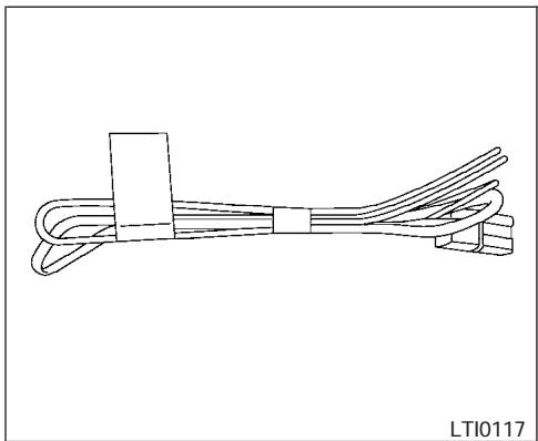
natural_image
Pure line drawing of a cable or wire structure with no text, numbers, or symbolsexample
Trailers equipped with electric brakes may require the installation of an aftermarket trailer brake controller.
Your vehicle is equipped with a connector and jumper harness that is specifically designed to be used when installing an aftermarket brake controller.
To install the electric trailer brake controller jumper harness, perform the following procedure:
- Open the driver door. Move the seat to the rearmost position.
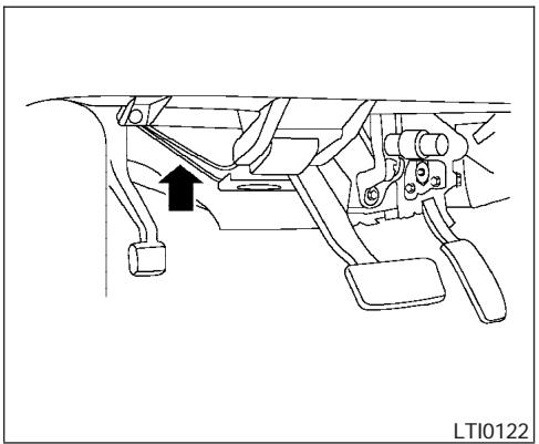
natural_image
Mechanical assembly diagram showing a lever mechanism with a black arrow indicating direction (no text or symbols present)- Apply the parking brake to access the jumper harness connector.
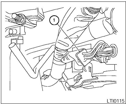
natural_image
Technical line drawing of a mechanical assembly with no visible text or symbols- Locate the jumper harness connector under the lower portion of the instrument panel. The connector is taped to the wiring harness ① as indicated.
- The connector is marked with a white tag with “electric brake connector”.
Wire color designation for electric trailer brake controller jumper harness.
| WIRE COLOR | NOTE |
| RED/GREEN | Vehicle stop lamp switch to trailer brake controller. |
| BLACK | Brake controller ground (-). |
| BROWN/WHITE | Trailer brake controller switched output. |
| RED/BLUE | Trailer brake controller illumination. |
| RED | Fused trailer brake controller battery feed (B+). |
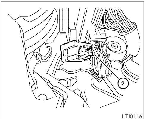
natural_image
Technical line drawing of a car's internal components, possibly engine or valve assembly (no text or symbols)- Peel off the tape and connect the jumper harness to the connector ②.
- Release the parking brake.
- Install the aftermarket electric trailer brake controller according to the manufacturer's instructions.
Pre-towing tips
- Be certain your vehicle maintains a level position when a loaded and/or unloaded trailer is hitched. Do not drive the vehicle if it has an abnormal nose-up or nose-down condition; check for improper tongue load, overload, worn suspension or other possible causes of either condition.
- Always secure items in the trailer to prevent load shift while driving.
- Load the trailer so approximately 60% of the trailer load is in the front half and 40% is in the back half.
- Check your hitch, trailer tire pressure, vehicle tire pressure, trailer light operation, and trailer wheel lug nuts every time you attach a trailer to the vehicle.
- Be certain your rearview mirrors conform to all federal, state or local regulations. If not, install any mirrors required for towing before driving the vehicle.
Trailer towing tips
In order to gain skill and an understanding of the vehicle's behavior, you should practice turning, stopping and backing up in an area which is free from traffic. Steering stability and braking performance will be somewhat different than under normal driving conditions.
- Always secure items in the trailer to prevent load shift while driving.
- Avoid abrupt starts, acceleration or stops.
- Avoid sharp turns or lane changes.
-
Always drive your vehicle at a moderate speed.
-
When backing up, hold the bottom of the steering wheel with one hand. Move your hand in the direction in which you want the trailer to go. Make small corrections and back up slowly. If possible, have someone guide you when you are backing up.
- Always block the wheels on both vehicle and trailer when parking. Parking on a slope is not recommended; however, if you must do so, first block the wheels and apply the parking brake, and then move the transmission shift selector lever into the P (Park) position. If you move the shift selector lever to the P (Park) position before blocking the wheels and applying the parking brake, transmission damage could occur.
- When going down a hill, shift into a lower gear and use the engine braking effect. When going up a long grade, downshift the transmission to a lower gear and reduce speed to reduce chances of engine overloading and/or overheating. However, for long steep grades, do not stay in 1st gear when driving above 35 MPH (56 km/h) or 2nd gear when driving above 58 MPH (93 km/h).
- If the engine coolant rises to an extremely high temperature when the air conditioner system is on, turn off the air conditioner.
Coolant heat can be additionally vented by opening the windows, switching the fan control to high and setting the temperature control to the HOT position.
- Trailer towing requires more fuel than normal circumstances.
- Avoid towing a trailer for your vehicle's first 500 miles (805 km).
- For the first 500 miles (805 km) that you do tow, do not drive over 50 MPH (80 km/h).
- Have your vehicle serviced more often than at intervals specified in the recommended Maintenance Schedule in the “NISSAN Service and Maintenance Guide”.
- When making a turn, your trailer wheels will be closer to the inside of the turn than your vehicle wheels. To compensate for this, make a larger than normal turning radius during the turn.
-
Crosswinds and rough roads will adversely affect vehicle/trailer handling, possibly causing vehicle sway. When being passed by larger vehicles, be prepared for possible changes in crosswinds that could affect vehicle handling. If swaying does occur, firmly grip the steering wheel, steer straight ahead, and immediately (but gradually) reduce vehicle speed. This combination will help stabilize the vehicle. Never increase speed.
-
Be careful when passing other vehicles. Passing while towing a trailer requires considerably more distance than normal passing. Remember, the length of the trailer must also pass the other vehicle before you can safely change lanes.
- To maintain engine braking efficiency and electrical charging performance, do not use overdrive.
- Avoid holding the brake pedal down too long or too frequently. This could cause the brakes to overheat, resulting in reduced braking efficiency.
- Increase your following distance to allow for greater stopping distances while towing a trailer. Anticipate stops and brake gradually
- Do not use cruise control while towing a trailer.
- Some states or provinces have specific speed limits for vehicles that are towing trailers. Obey the local speed limits.
- Check your hitch, trailer wiring harness connections, and trailer wheel lug nuts after 50 miles (80 km) of travel and at every break.
- When stopped in traffic for long periods of time in hot weather, put the vehicle in the P (Park) position.
When towing a trailer, final drive gear oil should be replaced and transmission oil/fluid should be changed more frequently. For additional information, see the "Maintenance and do-it-yourself" section earlier in this manual.
Tow mode
Tow mode should be used when pulling a heavy trailer or hauling a heavy load. Press the tow button to activate the tow mode. The tow indicator in the instrument panel illuminates when the tow mode is selected. Press the Tow button again to turn the tow mode OFF. The Tow mode is automatically cancelled when the key is turned OFF.
The Tow mode does the following:
- Reduces transmissions shifts when pulling a trailer or hauling a load.
- Provides similar shift feel to driver when the vehicle is towing.
The Tow mode should be used when the vehicle and trailer weight is at least 75% of the vehicle's GCWR. Tow mode is most useful in the following driving conditions when towing a heavy trailer or hauling a heavy load:
- Rolling terrain.
- Stop and go traffic.
- Busy parking lots.
Driving the vehicle in the Tow mode with no trailer/load or light trailer/light load will not cause any damage. However, fuel economy may be reduced and the transmission/engine driving characteristics may feel unusual.
When towing a trailer, final drive gear oil should be replaced and transmission oil/fluid should be changed more frequently. For additional information, see the "Maintenance and do-it-yourself" section earlier in this manual.
FLAT TOWING
Towing your vehicle with all four wheels on the ground is sometimes called flat towing. This method is sometimes used when towing a vehicle behind a recreational vehicle, such as a motor home.
CAUTION
- Failure to follow these guidelines can result in severe transmission damage.
- Whenever flat towing your vehicle, always tow forward, never backward.
- DO NOT tow any automatic transmission vehicle with all four wheels on the ground (flat towing). Doing so WILL DAMAGE internal transmission parts due to lack of transmission lubrication.
- For emergency towing procedures refer to “Towing recommended by NISSAN” in the “In case of emergency” section of this manual.
Automatic Transmission
To tow a vehicle equipped with an automatic transmission, an appropriate vehicle dolly MUST be placed under the towed vehicle's drive wheels. Always follow the dolly manufacturer's recommendations when using their product.
WARNING
Do not use this vehicle for snowplowing. Installing a snowplow may affect vehicle handling. This may cause the driver to lose control of the vehicle and could result in serious vehicle damage or personal injury.
UNIFORM TIRE QUALITY GRADING
DOT (Department of Transportation) Quality Grades: All passenger car tires must conform to federal safety requirements in addition to these grades.
Quality grades can be found where applicable on the tire sidewall between tread shoulder and maximum section width. For example:
Treadwear 200 Traction AA Temperature A
Treadwear
Treadwear grade is a comparative rating based on tire wear rate when tested under controlled conditions on specified government test courses. For example, a tire graded 150 would wear one and a half (1-1/2) times as well on the government course as a tire graded 100. However, relative tire performance depends on actual driving conditions, and may vary significantly due to variations in driving habits, service practices and differences in road characteristics and climate.
Traction AA, A, B and C
The traction grades, from highest to lowest, are AA, A, B, and C. Those grades represent the tire's ability to stop on wet pavement as measured under controlled conditions on specified government test surfaces of asphalt and concrete. A tire marked C may have poor traction performance.
WARNING
The traction grade assigned to your vehicle tires is based on straight-ahead braking traction tests and does not include acceleration, cornering, hydroplaning or peak traction characteristics.
Temperature A, B and C
Temperature grades are A (the highest), B, and C. They represent a tire's resistance to heat build-up, and its ability to dissipate heat when tested under controlled conditions on a specified indoor laboratory test wheel. Sustained high temperature can cause tire material to degenerate, reducing tire life. Excessive temperatures can lead to sudden tire failure. Grade C corresponds to a performance level which all passenger car tires must meet under the Federal Motor Vehicle Safety Standard No. 109. Grades A and B represent higher levels of performance on laboratory test wheels than the minimum required by law.
WARNING
The temperature grade for this tire is established for a tire that is properly inflated and not overloaded. Excessive speed, under-inflation, or excessive loading, either separately or in combination, can cause heat build-up and possible tire failure.
EMISSION CONTROL SYSTEM WARRANTY
Your NISSAN vehicle is covered by the following emission warranties:
For USA
- Emission Defects Warranty
- Emissions Performance Warranty
Details of these warranties may be found with other vehicle warranties in your Warranty Information Booklet which comes with your NISSAN vehicle. If you did not receive a Warranty Information Booklet, or it is lost, you may obtain a replacement by writing to:
- Nissan North America, Inc.
Consumer Affairs Department
P.O. Box 191
Gardena, CA 90248-0191
For Canada
Emission Control System Warranty
Details of these warranties may be found with other vehicle warranties in your Warranty Information Booklet which comes with your NISSAN vehicle. If you did not receive a Warranty Information Booklet, or it is lost, you may obtain a replacement by writing to:
- Nissan Canada Inc.
5290 Orbitor Drive
Mississauga, Ontario, L4W 4Z5
REPORTING SAFETY DEFECTS (US only)
If you believe that your vehicle has a defect which could cause a crash or could cause injury or death, you should immediately inform the National Highway Traffic Safety Administration (NHTSA) in addition to notifying NISSAN.
If NHTSA receives similar complaints, it may open an investigation, and if it finds that a safety defect exists in a group of vehicles, it may order a recall and remedy campaign. However, NHTSA cannot become involved in individual problems between you, your dealer, or NISSAN.
To contact NHTSA, you may call the Auto Safety Hotline toll-free at 1-888-327-4236. You may also write to: NHTSA, U.S. Department of Transportation, Washington, D.C. 20590. You can also obtain other information about motor vehicle safety from the Hotline.
You may notify NISSAN by contacting our Consumer Affairs Department, toll-free, at 1-800-NISSAN-1.
READINESS FOR INSPECTION/MAINTENANCE (I/M) TEST
Due to legal requirements in some states and Canadian Provinces, your vehicle may be required to be in what is called the “ready condition” for an Inspection/Maintenance (I/M) test of the emission control system.
The vehicle is set to the “ready condition” when it is driven through certain driving patterns. Usually, the ready condition can be obtained by ordinary usage of the vehicle.
If a powertrain system component is repaired or the battery is disconnected, the vehicle may be reset to a "not ready" condition. Before taking the I/M test, check the vehicle's inspection/maintenance test readiness condition. Turn the ignition switch ON without starting the engine. If the Malfunction Indicator Lamp (MIL) comes on steady for 20 seconds and then blinks for 10 seconds, the I/M test condition is "not ready". If the MIL does not blink after 20 seconds, the I/M test condition is "ready." If the MIL indicates the vehicle is in a "not ready" condition, drive the vehicle through the following pattern to set the vehicle to the ready condition. If you cannot or do not want to perform the driving pattern, a NISSAN dealer can conduct it for you.
Always drive the vehicle in a safe and prudent manner according to traffic conditions and obey all traffic laws.
- Start the engine when the engine coolant temperature gauge needle points to C. Allow the engine to idle until the gauge needle points between the C and H (normal operating temperature).
- Accelerate the vehicle to 55 MPH (88 km/h), then quickly release the accelerator pedal completely and keep it released for at least 10 seconds.
- Quickly depress the accelerator pedal for a moment, then drive the vehicle at a speed of 53 - 60 MPH (86 - 96 km/h) for at least 9 minutes.
- Stop the vehicle.
- Accelerate the vehicle to 35 MPH (55 km/h) and maintain the speed for 20 seconds.
- Repeat steps 4 through 5 at least 10 times.
-
Accelerate the vehicle to 55 MPH (88 km/h) and maintain the speed for at least 3 minutes.
-
Stop the vehicle. Place the transmission selector lever in the P (Park) or N (Neutral) position.
- Turn the engine off.
- Repeat steps 1 - 8 at least one more time.
If steps 1 through 7 are interrupted, repeat the preceding step. Any safe driving mode is acceptable between steps. Do not stop the engine until step 7 is completed.
Your vehicle is equipped with a variety of computers that monitor and control a number of systems to optimize performance and help service technicians with diagnosis and repair. Depending on the equipment on your vehicle, some of the computers monitor emission control systems, braking systems and air bag systems, just to name a few. Some data about vehicle operation may be stored in the computers for use during servicing. Other data may be stored if a crash event occurs. For example, air bag readiness, air bag performance, and seat belt use by the driver or passenger may be recorded, depending on vehicle equipment. These types of systems are sometimes called Event Data Recorders.
Special equipment can be used to access the electronic data that may be stored in the vehicle's computers (sounds are not recorded). NISSAN and NISSAN dealers have equipment to access some of this data; others may also have this equipment. The data may be retrieved during routine vehicle servicing or for special research. It might also be accessed with the consent of the vehicle owner or lessee, in response to a request by law enforcement, or as otherwise required or permitted by law.
Genuine Nissan Service Manuals
natural_image
Illustration of two wrenches on a black background (no text or symbols)OWNER'S MANUAL/SERVICE MANUAL ORDER INFORMATION
A genuine NISSAN Service Manual is the best source of service and repair information for your vehicle. Filled with wiring diagrams, illustrations and step-by-step diagnostic and adjustment procedures, this manual is the same one used by the factory trained technicians working at NISSAN dealerships. Also available are genuine NISSAN Owner's Manuals, and genuine NISSAN Service and Owner's Manuals for older NISSAN models.
For USA
For current pricing and availability of genuine NISSAN Service Manuals for the 2000 model year and later contact:
Tweddle Litho Company
1-800-450-9491
www.nissan-techinfo.com
For current pricing and availability of genuine NISSAN Service Manuals for the 1999 model year and prior, see a NISSAN dealer, or contact:
Resolve Corporation
20770 Westwood Road
Strongsville, OH 44136
1-800-247-5321
For current pricing and availability of genuine NISSAN Owner's Manuals for the 2005 model year and prior, see a NISSAN dealer, or contact:
Resolve Corporation 20770 Westwood Road Strongsville, OH 44136 1-800-247-5321
For Canada
To purchase a copy of a genuine NISSAN Service Manual or Owner's Manual please contact your nearest NISSAN dealer. For the phone number and location of a NISSAN dealer in your area call the NISSAN Information Center at 1-800-387-0122 and a bilingual NISSAN representative will assist you.
Also available are genuine NISSAN Service and Owner's Manuals for older NISSAN models.
IN THE EVENT OF A COLLISION
Unfortunately, accidents do occur. In this unlikely event, there is some important information you should know.
Many insurance companies routinely authorize the use of non-genuine collision parts in order to cut costs, among other reasons.
Insist on the use of genuine NISSAN collision parts!
If you want your vehicle to be restored using parts made to NISSAN's original exacting specifications – if you want to help it to last and hold its resale value, the solution is simple. Tell your insurance agent and your repair shop to only use Genuine NISSAN Collision Parts. NISSAN does not warrant non-NISSAN parts, nor does NISSAN's warranty apply to damage caused by a non-genuine part.
Using Genuine NISSAN Parts can help protect your personal safety, preserve your warranty protection and maintain the resale value of your vehicle. And if your vehicle was leased, using Genuine NISSAN Parts may prevent or limit unnecessary excess wear and tear expenses at the end of your lease.
NISSAN designs its hoods with crumple zones to minimize the risk that the hood will penetrate the windshield of your vehicle in an accident. Non-genuine (imitation) parts may not provide such built in safeguards. Also, non-genuine parts often show premature wear, rust and corrosion.
Why should you take a chance?
In over 40 states, the law says you must be advised if non-genuine parts are used to repair your vehicle. And some states have enacted laws that restrict insurance companies from authorizing the use of non-genuine collision parts during the new vehicle warranty. These laws help protect you, so you can take action to protect yourself.
It's your right!
If you should need further information visit us at: www.nissanusa.com.
MEMO
10 Index
4WD warning light .....2-15
A
Active head restraint .....1-9
Adjusting pedal position . . . . . . . . . . . . . . . . . . . . . . . . . . . . . . . . . . . . . . . . . . . . . . . . 3-16
Air bag (See supplemental restraint system) .....1-56
Air bag system Front (See supplemental front impact air bag system) .....1-63
Air bag warning labels .....1-70 Air bag warning light.....1-71, 2-16
Air cleaner housing filter .....8-16 Air conditioner
Air conditioner operation .....4-18
Air conditioner service .....4-27
Air conditioner specification label . . . . .9-11
Air conditioner system refrigerant and lubrication recommendations .....9-6
Heater and air conditioner controls....4-15, 4-24
Rear seat air conditioner .....4-27
Servicing air conditioner .....4-27
Air flow charts. . . . . . . . . . . . . . . . . . . . . . . . . . . . . . . . . . . . . . . . 4-19
Alarm system (See vehicle security system) .....2-20
Anchor point locations .....1-45
Antenna . . . . . . . . . . . . . . . . . . . . . . . . . . . . . . . . . . . . . . . . . . . . . 4-40
Anti-lock brake system (ABS) .....5-25
Anti-lock brake warning light. . . . . . . . . . .2-13
AM-FM-SAT radio with compact disc (CD) changer .....4-31
Compact Disc (CD) changer .....4-34
Radio 4-28
Rear audio controls. . . . . . . . . . . . . . . . . . . . . . . . . . . . . . . . . . . . . . . . . . . . . . 4-39
Steering wheel audio control switch. . . .4-37
Autolight switch....2-25
Automatic Automatic drive positioner .....3-19
Automatic power window switch .....2-46
Automatic transmission position indicator light . . . . . . . . . . . . . . . . . . . . . . . . . . . . . . . . . . . . . . . . . . . . . . . . . . . . 2-17
Driving with automatic transmission. . . . .5-9
Transmission selector lever lock release . .5-13
Automatic anti-glare inside mirror .....3-18
Automatic transmission fluid temperature gauge .....2-7
AUX jack. . . . . . . . . . . . . . . . . . . . . . . . . . . . . . . . . . . . . . . . . . . . . 4-36
B
Back door. . . . . . . . . . . . . . . . . . . . . . . . . . . . . . . . . . . . . . . . . . . . . . . 3-9
Back door release .....3-12
Battery....8-13
Charge warning light .....2-14
Battery replacement (See remote keyless entry system) .....8-24
Before starting the engine .....5-8
Belts (See drive belts) .....8-14
Booster seats .....1-50
Brake Anti-lock brake system (ABS) .....5-25
Brake booster....8-21
Brake fluid. . . . . . . . . . . . . . . . . . . . . . . . . . . . . . . . . . . . . . . . . . . . . . . . . . . . . . . . . . . . . 8-11
Brake light (See stop light). . . . . . . . . .8-27
Brake pedal . . . . . . . . . . . . . . . . . . . . . . . . . . . . . . . . . . . . . . . . . . . . . . . . . . 8-20
Brake system . . . . . . . . . . . . . . . . . . . . . . . . . . . . . . . . . . . . . . . . . . . . . 5-24
Brake warning light . . . . . . . . . . . . . . . . . . . 2-13
Brake wear indicators .....2-19, 8-20
Parking brake check . . . . . . . . . . . . . . . . . . .8-20
Parking brake operation .....5-14
Self-adjusting brakes. . . . . . . . . . . . . . . . . . . . . . . . . . . . . . . . . . . . . . . . . . . . . . . . . . . . . . . 8-20
Break-in schedule. . . . . . . . . . . . . . . . . . . . . . . . . . . . . . . . . . . . . . . . . . . . . . . . . . . . . . . . . . 5-16
Brightness control Instrument panel .....2-27
Brightness/Contrast button .....4-12 Control panel buttons .....4-12
Bulb check/instrument panel. . . . . . . . . . .2-12
Bulb replacement....8-27
C
Capacities and recommended fuel/lubricants. 9-2
Captain's chair adjustment (2nd row). . . . . .1-5
Car phone or CB radio .....4-50
Cargo light . . . . . . . . . . . . . . . . . . . . . . . . . . . . . . . . . . . . . . . . . . 2-52
Cargo net .....2-43
Cargo (See vehicle loading information) . . .9-12
CD care and cleaning . . . . . . . . . . . . . . . . . . . 4-37
CD changer (See audio system). . . . . . . . 4-34
Check engine indicator light
(See malfunction indicator lamp) .....2-17
Child restraint with top tether strap . . . . . .1-44
Child restraints. . . . . . . 1-17, 1-18, 1-25, 1-42
Precautions on child restraints . . .1-25, 1-50
Top tether strap anchor point locations . .1-45
Child safety rear door lock. . . . . . . . . . . . . . . 3-5
Chimes, audible reminders. . . . . . . . . . . . . 2-19
Cigarette lighter. . . . . . . . . . . . . . . . . . . . . . . . . 2-32
Cleaning exterior and interior .....7-2
Clock 4-32
(models with navigation system)....4-10
Clock set
Control panel buttons . . . . . . . . . . . . . 4-10
Cold weather driving . . . . . . . . . . . . . . . . . . . . . . . . . . . . . . . . . . . . . . . . . . . . . . . . 5-28
Compass display. . . . . . . . . . . . . . . . . . . . . . . . . . . . . . . 2-8
Console box .....2-34, 2-40
Control panel buttons . . . . . . . . . . . . . . . . . 4-2
Controls
Audio controls (steering wheel) .....4-37
Heater and air conditioner
controls. . . . . . . . . . . . . . . . . . . . . 4-15, 4-24
Rear audio controls. . . . . . . . . . . . . . . . . . . 4-39
Rear seat air conditioner .....4-27
Coolant
Capacities and recommended
fuel/lubricants. . . . . . . . . . . . . . . . . . . . . . . . . . . . . . . . . . . . . . . . . . . 9-2
Changing engine coolant .....8-8
Checking engine coolant level. . . . . . . .8-7
Engine coolant temperature gauge .....2-5
Corrosion protection. . . . . . . . . . . . . . . . . . . . . . . . . . 7-5
Cruise control. . . . . . . . . . . . . . . . . . . . . . . . . . . . . . . . . . . . . . . . . . . . . . . . . . . . . . . . . . 5-14
Cup holders. . . . . . . . . . . . . . . . . . . . . . . . . . . . . . . . . . . . . . . . 2-38
Curtain side-impact and rollover air bag . . .1-68
D
Daytime running light system
(Canada only)....2-26
Defroster switch
Rear window and outside mirror defroster switch .....2-24
Digital video disc DVD .....4-40
Dimensions and weights. . . . . . . . . . . . . . . . . . .9-8
Display controls (see control panel buttons) . .4-2
Door locks . . . . . . . . . . . . . . . . . . . . . . . . . . . . . . . . . . . . . . . . . . . . . 3-3
Door open warning light . . . . . . . . . . . . . . . . . 2-14
Drive belts....8-14
Drive positioner, Automatic. . . . . . . . . . . . . 3-19
Driving
Cold weather driving .....5-28
Driving with automatic transmission. . . . .5-9
Precautions when starting and driving . . .5-2
E
Economy - fuel . . . . . . . . . . . . . . . . . . . . . . . . . . . . . . . . . . . . . . . . . . . . . . . . . . . . . . . . . . 5-16
Emission control information label .....9-10
Emission control system warranty .....9-26
Engine
Before starting the engine .....5-8
Capacities and recommended fuel/lubricants. 9-2
Changing engine coolant .....8-8
Changing engine oil . . . . . . . . . . . . . . . . . . . . . . . . . . . . . . . . . . . . . . . . . . . . . . . . 8-9
Changing engine oil filter. . . . . . . . . . . .8-10
Checking engine coolant level. . . . . . . .8-7
Checking engine oil level .....8-8
Engine compartment check locations. . . .8-7
Engine coolant temperature gauge .....2-5
Engine cooling system. . . . . . . . . . . . . . . . . . . . . . . . . . . . . . . . . . . . . . . . . . . . . . . . . . . . . . . . . . . . 8-7
Engine oil . . . . . . . . . . . . . . . . . . . . . . . . . . . . . . . . . . . . . . . . . . . . . . . . . . . . . . . . . . 8-8
Engine oil and oil filter recommendation . .9-4
Engine oil viscosity .....9-5
Engine serial number .....9-10
Engine specifications. . . . . . . . . . . . . . . . . . 9-7
Starting the engine....5-9
Engine oil pressure gauge .....2-6
English/Metric button. . . . . . . . . . . . . . . . . . . . . . . . . . . . . . . . . . . . . . . . . . . . . . 4-10
Control panel buttons . . . . . . . . . . . . . 4-10
ENTER button . . . . . . . . . . . . . . . . . . . . . . . . . . . . . . . . . . . . 4-2
Enter button
Control panel buttons . . . . . . . . . . . . . . . 4-2
Event data recorders .....9-27
Exhaust gas (Carbon monoxide) .....5-2
Eyeglass case. . . . . . . . . . . . . . . . . . . . . . . . . . . . . . . . . . . . . . . . . . . . 2-35
F
Flashers
(See hazard warning flasher switch). . . . . .2-28
Flat tire . . . . . . . . . . . . . . . . . . . . . . . . . . . . . . . . . . . . . . . . . . . . . . . . . . . . . . . . . . 6-2
Floor mat positioning aid. . . . . . . . . . . . . . . . . . . . . . . . . . . . . . . . . . . . . . . . . . . . . . . . . . . . . . . . . . . 7-4
Fluid
Brake fluid. . . . . . . . . . . . . . . . . . . . . . . . . . . . . . . . . . . . . . . . . . . . . . . . . . . . . . . . . . . . 8-11
Capacities and recommended
fuel/lubricants. . . . . . . . . . . . . . . . . . . . . . . . . . . . . . . . . 9-2
Engine coolant . . . . . . . . . . . . . . . . . . . . . . . . . . . . . . . . . . . . . . . . . . . . . 8-7
Engine oil . . . . . . . . . . . . . . . . . . . . . . . . . . . . . . . . . . . . . . . . . . . . . . . . . . . . . . . . . . 8-8
Power steering fluid. . . . . . . . . . . . . . . . . . . . . . . . . . . . . . . . . . . . . . . . . . . . . . . . . . . . . . . . . . 8-11
Window washer fluid . . . . . . . . . . . . . . . . . . . .8-12
F.M.V.S.S. certification label .....9-10
Fog light switch. . . . . . . . . . . . . . . . . . . . . . . . . . . . . . . . . 2-28
Front air bag system
(See supplemental restraint system) .....1-63
Front seats . . . . . . . . . . . . . . . . . . . . . . . . . . . . . . . . . . . . . . . 1-2
Fuel
Capacities and recommended
fuel/lubricants. . . . . . . . . . . . . . . . . . . . . . . . . . . . . . . . . . . . . . . . . . . . 9-2
Fuel economy . . . . . . . . . . . . . . . . . . . . . . . . . . . . . . . . . . . . . . . . . . . . . . . . . . 5-16
Fuel filler cap . . . . . . . . . . . . . . . . . . . . . . . . . . . . . . . . . . 3-14
Fuel filler lid . . . . . . . . . . . . . . . . . . . . . . . . . . . . . . . . . . . . . . . . 3-14
Fuel filler lid and cap . . . . . . . . . . . . . . . . . . 3-14
Fuel gauge . . . . . . . . . . . . . . . . . . . . . . . . . . . . . . . . . 2-6
Fuel octane rating . . . . . . . . . . . . . . . . . . . . . . . . 9-3
Fuel recommendation .....9-3
FUEL ECON button . . . . . . . . . . . . . . . . . . . . . . . 4-4
Fuel Econ button
Control panel buttons . . . . . . . . . . . . . . . 4-4
Fuses 8-21
Fusible links . . . . . . . . . . . . . . . . . . . . . . . . . . . . . . . . . . . . . . . . . . . . . . . . . . . . . . . . . . . . . . 8-23
G
Garage door opener, HomeLink® Universal
Transceiver . . . . . . . . . . . . . . . . . . . . . . . . . . . . . . . . . . . . . . . . . . . . . 2-52
Gas cap . . . . . . . . . . . . . . . . . . . . . . . . . . . . . . . . . . . . . . . . . . 3-14
Gauge
Automatic transmission fluid temperature
gauge . . . . . . . . . . . . . . . . . . . . . . . . . . . . . . . . . . . . . . . . . 2-7
Engine coolant temperature gauge .....2-5
Engine oil pressure gauge. . . . . . . . . . . .2-6
Fuel gauge . . . . . . . . . . . . . . . . . . . . . . . . . . . . . . . . . . . . . . . . . . 2-6
Odometer. . . . . . . . . . . . . . . . . . . . . . . . . . . . . . . . . . . . . . . . 2-4
Speedometer. . . . . . . . . . . . . . . . . . . . . . . . . . . . . 2-4
Tachometer. . . . . . . . . . . . . . . . . . . . . . . . . . . . . . . . . . . . . . . . . . . . 2-5
Trip odometer. . . . . . . . . . . . . . . . . . . . . . . . . . . . . 2-4
Voltmeter . . . . . . . . . . . . . . . . . . . . . . . . . . . . . . . . . . . . . . . . . . 2-7
General maintenance .....8-2
Glass hatch . . . . . . . . . . . . . . . . . . . . . . . . . . . . . . . . . . . . . . . . . 3-14
Glove box . . . . . . . . . . . . . . . . . . . . . . . . . . . . . . . . . . . . . . . . . . . . . . . 2-35
H
Hazard warning flasher switch .....2-28
Head restraints . . . . . . . . . . . . . . . . . . . . . . . . . . . 1-8
Active head restraint .....1-9
Headlight and turn signal switch. . . . . . . .2-24
Headphones (See NISSAN mobile
entertainment system) .....4-43
Heated seats . . . . . . . . . . . . . . . . . . . . . . . . . . . . . . . . . . . . . . . . . . . . . 2-29
Heater
Heater and air conditioner
controls. . . . . . . . . . . . . . . . . . . . . . . 4-15, 4-24
Heater operation. . . . . . . . . . . . 4-16, 4-25
Rear seat air conditioner .....4-27
HomeLink® Universal Transceiver .....2-52
Hood release . . . . . . . . . . . . . . . . . . . . . . . . . . . . . . . . . . . . . . . . 3-9
Hook
Luggage hook. . . . . . . . . . . . . . . . . . . . . . . . . . . . . 2-42
Horn . . . . . . . . . . . . . . . . . . . . . . . . . . . . . . . . . . . . . . . . . . . . . . . . . . . 2-29
|
Ignition switch . . . . . . . . . . . . . . . . . . . . . . . . . . . . . . . . . . . . . . . . . . . . . . . . . . . . . . . . . . . . 5-7
Immobilizer system. . . . . . . . . . .2-21, 3-2, 5-8
Important vehicle information label. . . . . . .9-10
In-cabin microfilter . . . . . . . . . . . . . . . . . . . . . . . . . . . . . . . . . . . . . . . . . . . . . . . . . . . . . . . . . . 8-16
Increasing fuel economy . . . . . . . . . . . . . . . . . . . . . . . . . . . . . . . . . . . . . . . . . . . . . . . . . . . . . . . . . . . . 5-16
Indicator lights and audible reminders
(See warning/indicator lights and audible
reminders). . . . . . . . . . . . . . . . . . . . . . . . . . . . . . . . . . . . . . . . . . . . . 2-12
Inside automatic anti-glare mirror .....3-18
Instrument brightness control .....2-27
Instrument panel . . . . . . . . . . . . . . . . . . . 0-6, 2-2
Interior light . . . . . . . . . . . . . . . . . . . . . . . . . . . . . . . . . . . . . . . . . . 2-50
ISOFIX child restraints .....1-42
J
Jump starting . . . . . . . . . . . . . . . . . . . . . . . . . . . . . . . . . . . . . . . . . . . . . . . . . . . . . . . . . 6-7
K
Key 3-2
Keyless entry system
(See remote keyless entry system) .....3-5
L
Labels
Air conditioner specification label . . . . .9-11
Emission control information label . . . . .9-10
Engine serial number .....9-10
F.M.V.S.S. certification label .....9-10
Vehicle identification number (VIN) plate . .9-9
Warning labels (for SRS). . . . . . . . . . . 1-70
LATCH (Lower Anchors and Tethers for CHildren)
System. 1-42
License plate
Installing the license plate . . . . . . . . . .9-11
Light
Air bag warning light. . . . . . . . . 1-71, 2-16
Brake light (See stop light). . . . . . . . . . .8-27
Bulb check/instrument panel. . . . . . . .2-12
Bulb replacement....8-27
Charge warning light . . . . . . . . . . . . . . . 2-14
Fog light switch. . . . . . . . . . . . . . . . . . . . . . . . . . 2-28
Headlight and turn signal switch. . . . . .2-24
Interior light . . . . . . . . . . . . . . . . . . . . . . . . . . . 2-50
Light bulbs. . . . . . . . . . . . . . . . . . . . . . . . . . . . . . . . . . . . . . . . . . . . . . . . . . . . . . . 8-25
Low tire pressure warning light .....2-15
Low washer fluid warning light. . . . . . .2-16
Passenger air bag and status light .1-65, 2-18
Personal lights . . . . . . . . . . . . . . . . . . . . . . . . . 2-51
Security indicator light. . . . . . . . 1-65, 2-18
Warning/indicator lights and audible reminders .....2-12
Lights
Map lights . . . . . . . . . . . . . . . . . . . . . . . . . . . . . . . . . . . . . . . . . . . . 2-51
Lock
Back door release .....3-12
Child safety rear door lock. . . . . . . . . . .3-5
Door locks . . . . . . . . . . . . . . . . . . . . . . . . . . . . . . . . . . . . . . . . . 3-3
Power door locks. . . . . . . . . . . . . . . . . . . . . . . . . . . . 3-4
Low fuel warning light . . . . . . . . . . . . . . . . . . . . 2-15
Low tire pressure warning light .....2-15
Low tire pressure warning system. . . . . . . .5-3
Low washer fluid warning light. . . . . . . . .2-16
Luggage hook. . . . . . . . . . . . . . . . . . . . . . . . . . . . . . . . 2-42
Luggage rack (see roof rack) .....2-44
Luggage (See vehicle loading information) . .9-12
Luggage storage
(see vehicle loading information). . . . . . . .2-41
M
Maint (maintenance) button
Control panel buttons . . . . . . . . . . . . . . . . . . 4-4
Maint (Maintenance) button, control panel
display. . . . . . . . . . . . . . . . . . . . . . . . . . . . . . . . . . . . . . . . . . . . . . . . 4-4
Maintenance
General maintenance . . . . . . . . . . . . . . . . . 8-2
Inside the vehicle. . . . . . . . . . . . . . . . . . . . . . . . . . . . . . . . . . . 8-3
Maintenance precautions . . . . . . . . . . .8-5
Outside the vehicle. . . . . . . . . . . . . . . . . . . . . . . . . . . . . . . . . . . . . . . . . . . . . . . 8-2
Seat belt maintenance .....1-25
Under the hood and vehicle . . . . . . . . . .8-4
Malfunction indicator lamp (MIL).....2-17
Manual front seat adjustment .....1-2
Manual vent windows. . . . . . . . . . . . . . . . . . . . . 2-48
Map lights . . . . . . . . . . . . . . . . . . . . . . . . . . . . . . . . . . . . . . . . . . . . . . . . . 2-51
Map pocket . . . . . . . . . . . . . . . . . . . . . . . . . . . . . . . . . . . . . . . . . . . . . . . . 2-36
Meters and gauges. . . . . . . . . . . . . . . . . . . . . . . . . 2-3
Instrument brightness control .....2-27
Mirror
Automatic anti-glare inside mirror . . . . .3-18
Outside mirror control . . . . . . . . . . . . 3-18
Outside mirrors . . . . . . . . . . . . . . . . . . . . 3-18
Vanity mirror. . . . . . . . . . . . . . . . . . . . . . . . . . . . . . . . . . . . . . . 3-17
N
NISSAN mobile entertainment system
(MES) 4-40
Nissan vehicle immobilizer system
(NVIS). . . . . . . . . . . . . . . . . . . . . . . . . . . . . . . . . . 2-21, 3-2, 5-8
O
Octane rating (See fuel octane rating) .....9-3
Odometer. . . . . . . . . . . . . . . . . . . . . . . . . . . . . . . . . . . . . . . . . . . . 2-4
Oil
Capacities and recommended
fuel/lubricants. . . . . . . . . . . . . . . . . . . . . . . . . . . . . . . . . . . . . . . . . . . . 9-2
Changing engine oil . . . . . . . . . . . . . . . . . . . . . . . . . . . . . . . . . . . . . . . . . . . . . . . . . . . . . . . . . 8-9
Changing engine oil filter. . . . . . . . . . .8-10
Checking engine oil level .....8-8
Engine oil . . . . . . . . . . . . . . . . . . . . . . . . . . . . . . . . . . . . . . . . . . . . . . . . . . . . . . . . . . . 8-8
Engine oil and oil filter recommendation . .9-4
Engine oil viscosity .....9-5
Outside mirror control . . . . . . . . . . . . . . . . 3-18
Outside mirrors . . . . . . . . . . . . . . . . . . . . . . . . . . . . 3-18
Overheat
If your vehicle overheats . . . . . . . . . . . . . . .6-9
Owner's manual order form . . . . . . . . . . .9-28
Owner's manual/service manual order
information. . . . . . . . . . . . . . . . . . . . . . . . . . . . . . . . . . . . . . . . . . . . 9-28
P
Parking
Parking brake check . . . . . . . . . . . . . . . . . . . . . . . . . . . . . . . . . . . . . . . . . . . . . . . . 8-20
Parking brake operation .....5-14
Parking/parking on hills. . . . . . . . . . . . . . . . . . 5-23
Pedal position adjustment .....3-16
Personal lights . . . . . . . . . . . . . . . . . . . . . . . . . . . . . . . . . . . . . . . . 2-51
Power
Power door locks. . . . . . . . . . . . . . . . . . . . . . . . . . . . . . 3-4
Power outlet. . . . . . . . . . . . . . . . . . . . . . . . . . . . . . . . . 2-31
Power rear windows .....2-46
Power steering fluid. . . . . . . . . . . . . . . . . . . . . . . . . . . . . . . . . . . . . . . . . . . . . . . . . . . . . . . . . . . . 8-11
Power steering system .....5-24
Power vent windows .....2-47
Power windows. . . . . . . . . . . . . . . . . . . . . . . 2-45
Rear power windows. . . . . . . . . . . . . . . . 2-46
Precautions
Maintenance precautions . . . . . . . . . . . .8-5
On-pavement and off-road driving precautions . . . . . . . . . . . . . . . . . . . . . . . . . . . . . . . . . . . . . . . . . . . . . . . . . . . . . . . . 5-3
Precautions on child restraints . . .1-25, 1-50
Precautions on seat belt usage .....1-15
Precautions on supplemental restraint system....1-56
Precautions when starting and driving . . .5-2
Pre-tensioner seat belt system. . . . . . . . . 1-69
PREV button . . . . . . . . . . . . . . . . . . . . . . . . . . . . . . . . . . . . . . . . . 4-3
Prev button Control panel buttons .....4-3
Programmable features. . . . . . . . . . . . 4-3, 4-7
Push starting . . . . . . . . . . . . . . . . . . . . . . . . . . . . . . . . . . . . . . . . . . . . . . . . 6-9
R
Radio
Car phone or CB radio. . . . . . . . . . . . . . . 4-50
Compact Disc (CD) changer .....4-34
Rear audio controls. . . . . . . . . . . . . . . . . . . . 4-39
Steering wheel audio control switch. . . .4-37
Readiness for inspection maintenance (I/M) test. . . . . . . . . . . . . . . . . . . . . . . . . . . . . . . . . . . . . . . . . . . . . . . . . . . . . . . . . . 9-26
Rear audio controls....4-39
Rear center seat belt .....1-21
Rear power windows....2-46
Rear seat air conditioner . . . . . . . . . . . . . . . . . . 4-27
Rear sonar system off switch .....2-30
Rear view monitor. . . . . . . . . . . . . . . . . . . . . . . . . . . . . . 4-12
Rear window and outside mirror defroster switch . . . . . . . . . . . . . . . . . . . . . . . . . . . . . . . . . . . . . . . . . . . . . 2-24
Rear window wiper and washer switches. . .2-23
Recorders
Event data....9-27
Refrigerant recommendation .....9-6
Registering your vehicle in another country. . .9-9
Remote controller (See NISSAN mobile entertainment system) .....4-42
Remote keyless entry system .....3-5
Reporting safety defects (US only) .....9-26
Roof rack . . . . . . . . . . . . . . . . . . . . . . . . . . . . . . . . . . . . . . . . . . . . . 2-44
S
Safety
Child safety rear door lock. . . . . . . . . . . 3-5
Child seat belts .....1-25, 1-50
Reporting safety defects (US only) . . . .9-26
Screen (See NISSAN mobile entertainment system) .....4-42
Seat adjustment
Front manual seat adjustment .....1-2
Front power seat adjustment .....1-4
Second row bench seats .....1-7
Second row captain's chair .....1-5
Seat belt
Child safety .....1-17
Infants and small children .....1-18
Injured Person. . . . . . . . . . . . . . . . . . . . . . . . 1-19
Larger children .....1-18
Precautions on seat belt usage .....1-15
Pregnant women .....1-19
Pre-tensioner seat belt system. . . . . . .1-69
Rear center seat belt .....1-21
Seat belt extenders....1-24
Seat belt maintenance .....1-25
Seat belts . . . . . . . . . . . . . . . . . . . . . . . . . . . . 1-15
Shoulder belt height adjustment. . . . . . 1-24
Three-point type with retractor. . . . . . .1-19
Seat belt warning light . . . . . . . . . . . . . . . . . . . . 2-16
Seatback pockets. . . . . . . . . . . . . . . . . . . . . . 2-36
Seats
Adjustment .....1-2
Automatic drive positioner .....3-19
Front seats . . . . . . . . . . . . . . . . . . . . . . . . . . . . . . . . 1-2
Heated seats . . . . . . . . . . . . . . . . . . . . . . . . . . . . . . . . . 2-29
Manual front seat adjustment .....1-2
Second row captain's chair adjustment. . . . .1-5
Security indicator light. . . . . . . . . . . 1-65, 2-18
Security system (Nissan vehicle immobilizer system), engine start. . . . . . . . . 2-21, 3-2, 5-8
Self-adjusting brakes....8-20
Service manual order form .....9-28
Servicing air conditioner .....4-27
Setting button
SETTING button . . . . . . . . . . . . . . . . . . . . . . . . . . . . . . 4-7
Shift lock release .....5-13
Shifting
Automatic transmission. . . . . . . . . . . . . . . 5-11
Shoulder belt height adjustment.....1-24
Side air bag system (See supplemental side air bag, curtain and rollover air bag systems). . .1-68
Spark plug replacement .....8-15
Speedometer. . . . . . . . . . . . . . . . . . . . . . . . . . . . . . . . . . . 2-4
SRS warning label .....1-70
Starting
Before starting the engine .....5-8
Jump starting . . . . . . . . . . . . . . . . . . . . . . . . . . . . . . . . . . . . . . . . . . . 6-7
Precautions when starting and driving . . .5-2
Push starting . . . . . . . . . . . . . . . . . . . . . . . . . . . . . . . . . . . . . . . . . . . 6-9
Starting the engine. . . . . . . . . . . . . . . . . . . . . . . . . . . . . . . . . . . . . . . . . . . . . . . . 5-9
Startup Screen
Control panel buttons .....4-3
Startup screen display .....4-3
Steering
Power steering fluid. . . . . . . . . . . . . . . . . . . . . . . . . . . . . . . . . . . . . . . . . . . . . . . . . . . . . . . . . . . 8-11
Power steering system .....5-24
Tilting steering wheel. . . . . . . . . . . . . . . 3-16
Steering wheel audio control switch. . . . . .4-37
Stop light . . . . . . . . . . . . . . . . . . . . . . . . . . . . . . . . . . . . . . . . . . . . . . . . . . . . . . . . . . . 8-27
Storage . . . . . . . . . . . . . . . . . . . . . . . . . . . . . . . . . . . . . . . . . . . . . . . 2-33
Overhead storage compartment. . . . . . 2-37
Storage bin. . . . . . . . . . . . . . . . . . . . . . . . . . . . . 2-37, 2-41
Storage tray. . . . . . . . . . . . . . . . . . . . . . . . . . . . . . . . . . . . . . . . . . . . . 2-33
Sunvisors.3-17
Sunglasses case . . . . . . . . . . . . . . . . . . . . . . . . . 2-35
Sunglasses holder .....2-35
Sunroof . . . . . . . . . . . . . . . . . . . . . . . . . . . . . . . . . . . . . . . . . . 2-48
Supplemental air bag warning labels .....1-70
Supplemental air bag warning light. . .1-71, 2-16
Supplemental front impact air bag system . .1-63
Supplemental restraint system Information and warning labels. . . . . . .1-70
Precautions on supplemental restraint system....1-56
Supplemental restraint system
(Supplemental air bag system). . . . . . . . . 1-56
Switch
Autolight switch. . . . . . . . . . . . . . . . . . . . 2-25
Automatic power window switch .....2-46
Fog light switch. . . . . . . . . . . . . . . . . . . . . . . . . . 2-28
Hazard warning flasher switch .....2-28
Headlight and turn signal switch. . . . . .2-24
Ignition switch . . . . . . . . . . . . . . . . . . . . . . . . . . . . . . . . . . . . . . . . . . 5-7
Power door lock switch . . . . . . . . . . . . . . 3-4
Rear sonar system off switch .....2-30
Rear window and outside mirror defroster switch .....2-24
Rear window wiper and washer
switches. . . . . . . . . . . . . . . . . . . . . . . . . . . . . . . . . . . . . . . . . . . . . 2-23
Vehicle dynamic control (VDC) off
switch . . . . . . . . . . . . . . . . . . . . . . . . . . . . . . . . . . . . . . . . . . . . 2-30
Windshield wiper and washer switch . . .2-22
T
Tachometer. . . . . . . . . . . . . . . . . . . . . . . . . . . . . . . . . . . . . . . . . . . . . . 2-5
Temperature gauge
Engine coolant temperature gauge .....2-5
Theft (Nissan vehicle immobilizer system),
engine start. . . . . . . . . . . . . . . . . . . 2-21, 3-2, 5-8
Three-way catalyst .....5-2
Tilting steering wheel. . . . . . . . . . . . . . . . . . . . . . . . . . 3-16
Tire
Flat tire . . . . . . . . . . . . . . . . . . . . . . . . . . . . . . . . . . . . . . . . . . . . . . . . 6-2
Spare tire . . . . . . . . . . . . . . . . . . . . . . . . . . . . . . . . . . . . . . . . . . . . 6-3
Tire chains. . . . . . . . . . . . . . . . . . . . . . . . . . . . . . . . . . . . . . . . . . . . . . . . . . . . . . . . . . 8-38
Tire placard . . . . . . . . . . . . . . . . . . . . . . . . . . . . . . . . . . . . . . . . . . . . . 9-11
Tire pressure . . . . . . . . . . . . . . . . . . . . . . . . . . . . . . . . . . . . . . . . . . . . . . . . . 8-31
Tire rotation . . . . . . . . . . . . . . . . . . . . . . . . . . . . . . . . . . . . . . . . . . . . . . . . . . 8-39
Types of tires . . . . . . . . . . . . . . . . . . . . . . . . . . . . . . . . . . . . . . . . 8-38
Uniform tire quality grading. . . . . . . . . .9-25
Wheels and tires . . . . . . . . . . . . . . . . . . . . . . . . . . . . . . . . . . . . . . . . . . . . . . . 8-31
Wheel/tire size . . . . . . . . . . . . . . . . . . . . . . . . . . . . 9-8
Tire pressure
Low tire pressure warning light .....2-15
Tire pressure display. . . . . . . . . . . . . . . . . . . . 4-6
Tire rotation maintenance reminder .....4-6
Top tether strap child restraint .....1-44
Tow mode switch .....2-31
Towing
2-wheel drive models. . . . . . . . . . . . . . . . . . . . . . . . . . . . . . . . . . . . . . . . . . . . . . . . . . . . . . . . . . . . 6-11
4-wheel drive models. . . . . . . . . . . . . . . . . . . . . . . . . . . . . . . . . . . . . . . . . . . . . . . . . . . . . . . . . . . . 6-12
Flat towing. . . . . . . . . . . . . . . . . . . . . . . . . . . . . . . . . . . . . . . . . . . . . . 9-24
Tow truck towing . . . . . . . . . . . . . . . . . . . . . . . . . . . . . . . . . . . . . . . . . . . . . 6-10
Towing load/specification chart .....9-17
Trailer towing . . . . . . . . . . . . . . . . . . . . . . . . . . . . . . . 9-15
Transceiver
HomeLink® Universal Transceiver .....2-52
Transmission
Driving with automatic transmission. . . . .5-9
Selector lever lock release .....5-13
Travel (See registering your vehicle in another
country)....9-9
TRIP button. . . . . . . . . . . . . . . . . . . . . . . . . . . . . . . . . . . . . . . . . . . . 4-4
Trip button
Control panel buttons .....4-4
Trip odometer. . . . . . . . . . . . . . . . . . . . . . . . . . . . . . . . . . . . . . . . . 2-4
Turn signal switch (See headlight and
turn signal switch) . . . . . . . . . . . . . 2-24, 2-27
U
Uniform tire quality grading. . . . . . . . . . . . .9-25
V
Vanity mirror. . . . . . . . . . . . . . . . . . . . . . . . . . . . . . . . . . . . . . . . . . . . . . 3-17
Vehicle dimensions and weights .....9-8
Vehicle dynamic control (VDC) off switch. . .2-30
Vehicle dynamic control (VDC) system . . . .5-26
Vehicle electronic system .....4-8
Vehicle identification .....9-9
Vehicle identification number (VIN)
(Chassis number). . . . . . . . . . . . . . . . . . . . . . . . . . . . . . . . . . . . . . . . . . . . 9-9
Vehicle identification number (VIN) plate . . . .9-9
Vehicle loading information. . . . . . . . . . . . .9-12
Vehicle recovery .....6-12, 7-2
Vehicle security system. . . . . . . . . . . . . . . . . . 2-20
Vehicle security system (Nissan vehicle
immobilizer system), engine start . .2-21, 3-2, 5-8
Ventilators....4-14
Visors . . . . . . . . . . . . . . . . . . . . . . . . . . . . . . . . . . . . . . . . . . . . . . . 3-17
Voltmeter . . . . . . . . . . . . . . . . . . . . . . . . . . . . . . . . . . . . . . . . . . . . . . . . 2-7
W
Warning
4WD warning light . . . . . . . . . . . . . . . . . . 2-15
Air bag warning light. . . . . . . . . 1-71, 2-16
Anti-lock brake warning light. . . . . . . .2-13
Battery charge warning light .....2-14
Brake warning light . . . . . . . . . . . . . . . . . . 2-13
Door open warning light . . . . . . . . . . .2-14
Hazard warning flasher switch .....2-28
Low fuel warning light . . . . . . . . . . . . .2-15
Low tire pressure warning light .....2-15
Low washer fluid warning light. . . . . . .2-16
Passenger air bag and status light. . . . .1-65
Seat belt warning light .....2-15
Vehicle security system. . . . . . . . . . . . . 2-20
Warning labels (for SRS). . . . . . . . . . . 1-70
Warning/indicator lights and audible
reminders . . . . . . . . . . . . . . . . . . . . . . . . . . . . . . . . . . . 2-12
Warning lights. . . . . . . . . . . . . . . . . . . . . . . . . . . . . . . . . . . . . . . . . 2-12
Washer switch
Rear window wiper and washer
switches. . . . . . . . . . . . . . . . . . . . . . . . . . . . . . . . . . . . . . . . . 2-23
Windshield wiper and washer switch . . .2-22
Weights (See dimensions and weights) . . . .9-8
Wheels and tires . . . . . . . . . . . . . . . . . . . . . . . . . . . . . . . . . . . . . . . . . . . . . . . . . . . . 8-31
Wheel/tire size . . . . . . . . . . . . . . . . . . . . . . . . . . . . . . . . . . . . . . . . . . . . . . . . . . . . . 9-8
When traveling or registering your vehicle in
another country. . . . . . . . . . . . . . . . . . . . . . . . . . . . . . . . . . . . . . . . . . . 9-9
Window washer fluid . . . . . . . . . . . . . . . . . . . . . . . . . . . . . . . . . . . . . . . . . . . . . . . . . . . . . . . . . . . 8-12
Windows
Locking passengers' windows. . . . . . .2-46
Manual vent windows. . . . . . . . . . . . . . . 2-48
Power rear windows . . . . . . . . . . . . . . . . . . 2-46
Power vent windows .....2-47
Power windows .....2-45
Rear power windows .....2-46
Windshield wiper and washer switch . . . . .2-22
Wiper
Rear window wiper and washer
switches. . . . . . . . . . . . . . . . . . . . . . . . . . . . . . . . . . . . . . . . . . . . . . 2-23
Windshield wiper and washer switch . . .2-22
Wiper blades . . . . . . . . . . . . . . . . . . . . . . . . . . . . . . . . . . . . . . . . . . . . . . . . . . 8-17
MEMO
MEMO
MEMO
GAS STATION INFORMATION
RECOMMENDED FUEL:
Use unleaded regular gasoline with an octane rating of at least 87 AKI (Anti-Knock Index) number (Research octane number 91).

CAUTION
- Using a fuel other than that specified could adversely affect the emission control system, and may also affect the warranty coverage.
- Under no circumstances should a leaded gasoline be used, because this will damage the three-way catalyst.
For additional information, see “Capacities and recommended fuel/lubricants in the “Technical and consumer information” section.
RECOMMENDED ENGINE OIL:
- API Certification Mark
- API grade SL, Energy Conserving
- ILSAC grade GF-III
- 5W-30 Viscosity preferred
See “Engine oil and oil filter recommendation” in the “Technical and consumer information” section of this manual.
TIRE COLD PRESSURE:
See Tire and Loading Information label.
RECOMMENDED NEW VEHICLE BREAK-IN PROCEDURE:
During the first 1,200 miles (2,000 km) of vehicle use, follow the recommendations outlined in the "BREAK-IN SCHEDULE" information found in the "Starting and driving" section of this manual. Follow these recommendations for the future reliability and economy of your new vehicle. Failure to follow these recommendations may result in vehicle damage or shortened engine life.
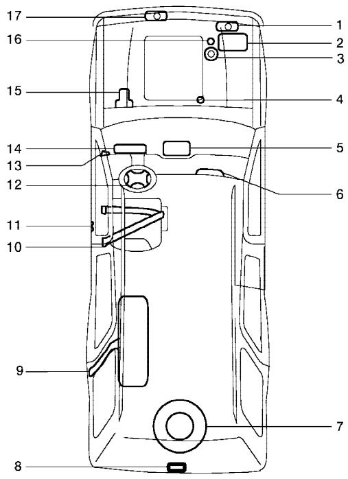
WGS0021
- Engine coolant 8-7
- Battery 8-13
- Power steering fluid 8-11
- Automatic transmission fluid 8-11
- Heater and air conditioner 4-15, 4-24 Audio system 4-28
- Passenger supplemental air bag 1-56
- Spare tire 6-2
- Rear door lock 9-12
- Fuel filler cap 3-14; Fuel recommendations 9-3
- Seat belts 1-15
- Door locks 3-3
- Driver supplemental air bag 1-56
- Hood release 3-9
- Meters and gauges 2-3
- Brake fluid 8-12
- Engine oil 8-8
- Window washer fluid 8-12
- READ FIRST—THEN DRIVE SAFELY
- WARNING
- IMPORTANT SAFETY INFORMATION REMINDERS FOR SAFETY!
- ON-PAVEMENT AND OFF-ROAD DRIVING
- MODIFICATION OF YOUR VEHICLE
- WHEN READING THE MANUAL
- IMPORTANT INFORMATION ABOUT THIS MANUAL
- CAUTION
- CALIFORNIA PROPOSITION 65 WARNING
- WELCOME TO THE WORLD OF NISSAN
- NISSAN CUSTOMER CARE PROGRAM
- NISSAN CARES ...
- Table of Contents
- Illustrated table of contents
- AIRBAGS, SEAT BELTS AND CHILD RESTRAINTS
- EXTERIOR REAR
- PASSENGER COMPARTMENT
- ENGINE COMPARTMENT CHECK LOCATIONS
- WARNING/INDICATOR LIGHTS
- Safety—Seats, seat belts and supplemental restraint system
- Forward and backward
- Reclining
- FRONT POWER SEAT
- Operating tips
- 1-4 Safety—Seats, seat belts and supplemental restraint system
- 2ND ROW BENCH SEAT ADJUSTMENT (if so equipped)
- HEAD RESTRAINT ADJUSTMENT
- ARMRESTS
- FLEXIBLE SEATING
- Folding the front passenger's seatback
- Folding the 3rd row bench seat
- SEAT BELTS
- PRECAUTIONS ON SEAT BELT USAGE
- CHILD SAFETY
- Infants
- Small Children
- Larger children
- PREGNANT WOMEN
- INJURED PERSONS
- THREE-POINT TYPE SEAT BELT WITH RETRACTOR
- Unfastening the seat belts
- Checking seat belt operation
- Center of the 3rd row bench seat
- Stowing the 3rd row center seat belt
- Attaching the 3rd row center seat belt
- Front and 2nd row outboard seats
- SEAT BELT EXTENDERS
- CHILD RESTRAINTS
- SEAT BELT MAINTENANCE
- CHILD RESTRAINT INSTALLATION ON 2ND ROW CAPTAIN'S CHAIRS
- Front facing
- Front Facing — step 5
- Rear Facing — step 1
- Rear facing
- Rear Facing — step 5
- CHILD RESTRAINT INSTALLATION ON 3RD ROW BENCH SEAT
- TOP TETHER STRAP CHILD RESTRAINT
- Anchor point locations
- 2nd row captain's chairs (if so equipped)
- BOOSTER SEATS
- PRECAUTIONS ON BOOSTER SEATS
- (Center position)
- (Outboard position)
- SUPPLEMENTAL RESTRAINT SYSTEM
- PRECAUTIONS ON SUPPLEMENTAL RESTRAINT SYSTEM
- NISSAN Advanced Air Bag System (front seats)
- Front passenger air bag and status light
- Status light
- Front passenger air bag
- SUPPLEMENTAL AIR BAG WARNING LABELS
- SUPPLEMENTAL AIR BAG WARNING LIGHT
- Repair and replacement procedure
- MEMO
- Instruments and controls
- METERS AND GAUGES
- SPEEDOMETER AND ODOMETER
- Speedometer
- Odometer/Twin trip odometer
- Changing the display:
- Resetting the trip odometer:
- TACHOMETER
- ENGINE COOLANT TEMPERATURE GAUGE
- FUEL GAUGE
- ENGINE OIL PRESSURE GAUGE
- VOLTMETER
- AUTOMATIC TRANSMISSION FLUID TEMPERATURE GAUGE (if so equipped)
- COMPASS AND OUTSIDE TEMPERATURE DISPLAY
- OUTSIDE TEMPERATURE DISPLAY
- Type B
- COMPASS DISPLAY
- Zone variation change procedure
- Inaccurate compass direction
- WARNING/INDICATOR LIGHTS AND AUDIBLE REMINDERS
- CHECKING BULBS
- WARNING LIGHTS
- If the light comes on while you are driving, contact a NISSAN dealer for repair.
- Charge warning light
- CK SUSP
- 4WD
- 4WD warning light (4x4 model)
- Low fuel warning light
- Low tire pressure warning light
- Low tire pressure warning:
- Low windshield washer fluid warning light
- Seat belt warning light and chime
- INDICATOR LIGHTS
- CRUISE Cruise main switch indicator light
- SET Cruise set switch indicator light
- 4WD shift indicator light (4x4 model)
- OFF or 2
- High beam indicator light (Blue)
- SERVICE ENGINE SOON Malfunction indicator lamp (MIL)
- Operation
- Security indicator light (NVIS)
- SLIP
- Slip indicator light
- 4LO
- Transfer 4LO position
- indicator light (4x4 model)
- The indicator light may blink while shifting from one drive mode to the other.
- Vehicle dynamic control off indicator light
- AUDIBLE REMINDERS Brake pad wear warning
- Key reminder chime
- Light reminder chime
- VEHICLE SECURITY SYSTEM
- How to arm the vehicle security system
- Vehicle security system activation
- How to stop an activated alarm
- NISSAN VEHICLE IMMOBILIZER SYSTEM (NVIS)
- WINDSHIELD WIPER AND WASHER SWITCH
- Security indicator light
- SWITCH OPERATION
- NOTE:
- REAR WINDOW WIPER AND WASHER SWITCH
- REAR WINDOW AND OUTSIDE MIRROR DEFROSTER SWITCH
- HEADLIGHT AND TURN SIGNAL SWITCH
- HEADLIGHT CONTROL SWITCH
- Lighting
- Autolight system
- Headlight beam select
- Battery saver system
- DAYTIME RUNNING LIGHT SYSTEM (Canada only)
- INSTRUMENT BRIGHTNESS CONTROL
- TURN SIGNAL SWITCH
- Turn signal
- Lane change signal
- HAZARD WARNING FLASHER SWITCH
- FOG LIGHT SWITCH (if so equipped)
- VEHICLE DYNAMIC CONTROL (VDC) OFF SWITCH
- REAR SONAR SYSTEM OFF SWITCH (if so equipped)
- TOW MODE SWITCH
- POWER OUTLET
- Front row
- 2nd row
- CIGARETTE LIGHTER
- Luggage area
- STORAGE
- CONSOLE BOX
- SEATBACK POCKET
- OVERHEAD CONSOLE
- CUP HOLDERS
- LUGGAGE HOOKS
- Side finisher
- Floor hooks
- CARGO NET
- ROOF RACK
- WINDOWS
- POWER WINDOWS
- Driver's side power window switch
- Locking passengers' windows
- Automatic operation
- Auto-reverse function
- POWER VENT WINDOWS (if so equipped)
- SUNROOF (if so equipped)
- MANUAL VENT WINDOWS (if so equipped)
- AUTOMATIC SUNROOF
- Sliding the sunroof
- Tilting the sunroof
- Restarting the sunroof sliding switch
- When closing:
- When tilting down:
- Sunshade
- INTERIOR LIGHT
- PERSONAL LIGHTS
- CONSOLE LIGHT
- MAP LIGHTS
- HOMELINK® UNIVERSAL TRANSCEIVER
- PROGRAMMING HOMELINK®
- PROGRAMMING HOMELINK® FOR CANADIAN CUSTOMERS
- PROGRAMMING TROUBLE-DIAGNOSIS
- CLEARING THE PROGRAMMED INFORMATION
- REPROGRAMMING A SINGLE HOMELINK® BUTTON
- IF YOUR VEHICLE IS STOLEN
- FCC Notice:
- Pre-driving checks and adjustments
- NISSAN VEHICLE IMMOBILIZER SYSTEM (NVIS) KEYS
- Never leave these keys in the vehicle.
- 3-2 Pre-driving checks and adjustments
- LOCKING WITH KEY
- Opening and closing windows
- LOCKING WITH INSIDE LOCK KNOB
- LOCKING WITH POWER DOOR LOCK SWITCH
- Lockout protection
- REMOTE KEYLESS ENTRY SYSTEM
- CHILD SAFETY REAR DOOR LOCK
- Be sure to remove the key from the vehicle before locking the doors.
- Locking doors
- Unlocking doors
- Auto relock
- Opening windows
- The door windows cannot be closed by using the keyfob.
- Linking the keyfob to automatic drive positioner memory
- Operating the power back door (if so equipped)
- Using the panic alarm
- Silencing the horn beep feature
- Using the interior lights
- Power Open:
- Power Close:
- Reverse:
- Auto Reverse:
- Manual Mode:
- Safe Mode:
- CANCEL SWITCH
- BACK DOOR RELEASE
- 3-12 Pre-driving checks and adjustments
- GLASS HATCH
- FUEL FILLER LID
- FUEL FILLER CAP
- STEERING WHEEL
- TILT OPERATION
- PEDAL POSITION ADJUSTMENT
- VANITY MIRRORS
- AUTOMATIC ANTI-GLARE INSIDE MIRROR
- OUTSIDE MIRRORS
- Foldable outside mirrors
- Heated mirrors
- AUTOMATIC DRIVE POSITIONER (if so equipped)
- MEMORY STORAGE FUNCTION
- Linking a keyfob to a stored memory position
- If a new memory is saved to the memory switch, the keyfob must be re-linked.
- Confirming memory storage
- Selecting the memorized position
- ENTRY/EXIT FUNCTION
- SYSTEM OPERATION
- Display screen, heater, air conditioner and audio systems
- CONTROL PANEL BUTTONS (if so equipped)
- 4-2 Display screen, heater, air conditioner and audio systems
- NAMES OF THE COMPONENTS
- HOW TO USE JOYSTICK AND "ENTER" BUTTON
- HOW TO USE "PREV" BUTTON
- SETTING UP THE START-UP SCREEN
- HOW TO USE THE "TRIP" BUTTON
- Trip 1, trip 2 and fuel economy items
- Maintenance items
- Tire pressure information
- HOW TO USE THE "SETTING" BUTTON
- SETTING THE DISPLAY (Audio or HVAC display):
- Display settings
- Brightness/Contrast/Map Background:
- Display Off:
- Setting Audio or HVAC display:
- Vehicle electronic systems
- Adjust driver seat when exiting vehicle:
- Remote unlock driver's door first:
- Keyless remote response — horn:
- Keyless remote response — lights:
- Auto re-lock time:
- Sensitivity of automatic headlights:
- Automatic headlights off delay:
- Speed dependent wiper:
- Return all settings to default:
- System settings
- Language/Unit
- Clock
- Adjusting the time:
- Setting daylight savings time:
- Adjusting the time to the GPS:
- Selecting the time zone:
- REARVIEW MONITOR (if so equipped)
- Beep setting
- BUTTON
- HOW TO READ THE DISPLAYED LINES
- VENTILATORS
- HEATER AND AIR CONDITIONER (manual)
- CONTROLS
- Temperature control dial
- Air recirculation button
- ON position:
- OFF position:
- A/C
- Air conditioner button
- The air conditioner cooling function operates only when the engine is running.
- Rear window defroster switch
- HEATER OPERATION
- Heating
- Ventilation
- Defrosting or defogging
- Bi-level heating
- Heating and defogging
- AIR CONDITIONER OPERATION
- Cooling
- Dehumidified heating
- AIR FLOW CHARTS
- REAR SEAT A/C FAN CONTROLS
- HEATER AND AIR CONDITIONER
- (automatic) (if so equipped)
- Cooling or heating (auto)
- Dehumidified defrosting or defogging
- MANUAL OPERATION
- Fan speed control
- Air recirculation
- Air flow control
- To turn system off
- REAR CONTROL BUTTON
- REAR SEAT AIR CONDITIONER
- SERVICING AIR CONDITIONER
- This refrigerant does not harm the earth's ozone layer.
- AUDIO SYSTEM
- RADIO
- Using a cellular phone in or near the vehicle may influence radio reception quality.
- Radio reception
- FM RADIO RECEPTION
- AM RADIO RECEPTION
- SATELLITE RADIO RECEPTION (if so equipped)
- Compact disc (CD) player
- Type A
- FM-AM-SAT RADIO WITH COMPACT DISC CHANGER (Type A and B) (if so equipped)
- Audio main operation
- POWER/VOLUME control:
- AUDIO knob (BASS, MIDRANGE, TREBLE, FADE, BALANCE and SSV if so equipped):
- Clock set (type B only)
- Display CD text:
- Display satellite radio text (if so equipped):
- Pause/mute button:
- FM/AM/SAT radio operation
- FM/AM/SAT band select:
- TUNE (Tuning):
- The radio should not be tuned while driving so full attention may be given to vehicle operation.
- SEEK tuning:
- SCAN tuning:
- Station memory operations:
- Radio data system (RDS):
- RDS can display:
- Program type (PTY):
- LOAD button:
- CD button:
- REW (Rewind), FF (Fast Forward):
- SEEK/TRACK:
- CD select buttons:
- REPEAT (RPT):
- REAR AV:
- (SPEAKER CONTROL) button:
- CD EJECT:
- CD IN indicator:
- AUX jack (if so equipped)
- CD CARE AND CLEANING
- STEERING WHEEL SWITCH FOR AUDIO CONTROL (if so equipped)
- POWER on/off switch
- MODE select switch
- Volume control switch
- Memory change (radio):
- Seek tuning (radio):
- FF, REW:
- REAR AUDIO CONTROLS (if so equipped)
- NISSAN MOBILE ENTERTAINMENT SYSTEM (MES) (if so equipped)
- VOL (volume) button:
- MODE button:
- SEEK button:
- NEXT button:
- ANTENNA
- Power ON/OFF:
- Volume control:
- PLAYING A DIGITAL VIDEO DISC (DVD)
- POWER on/off button:
- MODE select button:
- PLAY:
- FF (Fast Forward), REW (Remote control only):
- NEXT CHAPTER/ PREVIOUS CHAPTER (Remote control only):
- PAUSE:
- STOP:
- EJECT:
- DISPLAY:
- NAVIGATION KEYS:
- ENTER:
- MENU:
- TITLE (Remote control only):
- BACK (Remote control only):
- SUBTITLE (Remote control only):
- AUDIO (Remote control only):
- ANGLE (Remote control only):
- CLEAR (Remote control only):
- NUMERIC KEYPAD (0–9 & ≥10) (Remote control only):
- Auxiliary input jacks
- CARE AND MAINTENANCE
- HOW TO HANDLE THE DVD
- CAR PHONE OR CB RADIO
- Starting and driving
- PRECAUTIONS WHEN STARTING AND DRIVING
- THREE-WAY CATALYST
- ON-PAVEMENT AND OFF-ROAD DRIVING PRECAUTIONS
- Utility vehicles have a significantly higher rollover rate than other types of vehicles.
- LOW TIRE PRESSURE WARNING SYSTEM
- Low tire pressure warning
- DRIVING SAFETY PRECAUTIONS
- AUTOMATIC TRANSMISSION
- The shift selector lever can be moved if the ignition switch is in the ON position and the foot brake pedal is depressed.
- When the ignition is in the OFF position, the steering wheel is not locked.
- KEY POSITIONS
- BEFORE STARTING THE ENGINE
- STARTING THE ENGINE
- DRIVING THE VEHICLE
- ENGINE PROTECTION MODE
- Starting the vehicle
- Shifting
- P (Park):
- R (Reverse):
- Use this position only when the vehicle is completely stopped.
- N (Neutral):
- D (Drive):
- (Fourth gear):
- (Third gear):
- (Second gear):
- (Low gear):
- Shift lock release
- Accelerator downshift — in D position —
- Fail-safe
- To release:
- PRECAUTIONS ON CRUISE CONTROL
- Do not use the cruise control when driving under the following conditions:
- BREAK-IN SCHEDULE
- INCREASING FUEL ECONOMY
- TRANSFER CASE SHIFTING PROCEDURES
- 4WD warning light
- POWER STEERING
- BRAKE SYSTEM
- BRAKE PRECAUTIONS
- Vacuum assisted brakes
- Using the brakes
- Wet brakes
- Parking brake break-in
- Using the system
- Normal operation
- Self-test feature
- VEHICLE DYNAMIC CONTROL (VDC) SYSTEM (if so equipped)
- REAR SONAR SYSTEM (if so equipped)
- COLD WEATHER DRIVING
- FREEING A FROZEN DOOR LOCK
- ANTI-FREEZE
- BATTERY
- DRAINING OF COOLANT WATER
- TIRE EQUIPMENT
- Skid and traction capabilities of studded snow tires on wet or dry surfaces may be poorer than that of non-studded snow tires.
- SPECIAL WINTER EQUIPMENT
- DRIVING ON SNOW OR ICE
- In case of emergency
- CHANGING A FLAT TIRE
- Stopping the vehicle
- Blocking wheels
- Be sure to block the wheel as the vehicle may move and result in personal injury.
- Getting the spare tire and tools
- Carefully read the caution label attached to the jack body and the following instructions.
- JUMP STARTING
- PUSH STARTING
- IF YOUR VEHICLE OVERHEATS
- Do not stop the engine.
- TOWING YOUR VEHICLE
- TOWING RECOMMENDED BY NISSAN
- Two-wheel drive models
- Four-wheel drive models
- Appearance and care
- CLEANING EXTERIOR
- Be careful not to scratch the paint surface when putting on or removing the body cover.
- WASHING
- WAXING
- REMOVING SPOTS
- 7-2 Appearance and care
- CLEANING INTERIOR
- UNDERBODY
- GLASS
- ALUMINUM ALLOY WHEELS
- CHROME PARTS
- FLOOR MATS
- CORROSION PROTECTION
- MOST COMMON FACTORS CONTRIBUTING TO VEHICLE CORROSION
- ENVIRONMENTAL FACTORS INFLUENCE THE RATE OF CORROSION
- Moisture
- Relative humidity
- Temperature
- Air pollution
- TO PROTECT YOUR VEHICLE FROM CORROSION
- In winter, the underbody must be cleaned periodically.
- Maintenance and do-it-yourself
- MAINTENANCE REQUIREMENTS
- Scheduled maintenance
- General maintenance
- 8-2 Maintenance and do-it-yourself
- Where to go for service
- EXPLANATION OF GENERAL MAINTENANCE ITEMS
- Outside the vehicle
- Under the hood and vehicle
- 8-4 Maintenance and do-it-yourself
- MAINTENANCE PRECAUTIONS
- ENGINE COOLING SYSTEM
- CHECKING ENGINE COOLANT LEVEL
- ENGINE OIL
- CHANGING ENGINE COOLANT
- CHECKING ENGINE OIL LEVEL
- CHANGING ENGINE OIL
- CHANGING ENGINE OIL FILTER
- POWER STEERING FLUID
- BRAKE FLUID
- WINDOW WASHER FLUID
- WINDOW WASHER FLUID RESERVOIR
- DRIVE BELTS
- SPARK PLUGS
- REPLACING SPARK PLUGS
- Platinum-tipped spark plugs
- IN-CABIN MICROFILTER
- WINDSHIELD WIPER BLADES
- CLEANING
- REPLACING
- Rear window wiper blade
- CHECKING BRAKE PEDAL
- Distance A: Under depression force of 110 lb (490 N)
- Self-adjusting brakes
- Brake pad wear indicators
- FUSES
- BRAKE BOOSTER
- 8-22 Maintenance and do-it-yourself
- Fusible links
- BATTERY REPLACEMENT
- LIGHTS
- HEADLIGHTS
- FOG LIGHTS (if so equipped)
- Replacing the fog light bulb
- Replacement procedures
- WHEELS AND TIRES
- TIRE PRESSURE
- Checking tire pressure
- TIRE LABELING
- P215/65R15 95H
- DOT XX XX XXX XXXX
- Other Tire-related Terminology
- TYPES OF TIRES
- All season tires
- Summer tires
- Snow tires
- TIRE CHAINS
- Tire chains must be installed only on the rear wheels and not on the front wheels.
- CHANGING WHEELS AND TIRES
- Wheel nut tightening torque:
- Replacing wheels and tires
- Wheel balance
- Care of wheels
- Technical and consumer information
- CAPACITIES AND RECOMMENDED FUEL/LUBRICANTS
- 9-2 Technical and consumer information
- FUEL RECOMMENDATION
- Reformulated gasoline
- Gasoline containing oxygenates
- Take care not to spill gasoline during refueling. Gasoline containing oxygenates can cause paint damage.
- Aftermarket fuel additives
- Octane rating tips
- ENGINE OIL AND OIL FILTER RECOMMENDATION
- Oil additives
- Oil viscosity
- Selecting the correct oil filter
- Change intervals
- RECOMMENDED SAE VISCOSITY NUMBER
- AIR CONDITIONER SYSTEM REFRIGERANT AND LUBRICANT RECOMMENDATIONS
- WHEN TRAVELING OR REGISTERING YOUR VEHICLE IN ANOTHER COUNTRY
- VEHICLE IDENTIFICATION
- TERMS
- VEHICLE LOAD CAPACITY
- Steps for determining correct load limit
- LOADING TIPS
- TOWING A TRAILER
- MEASUREMENT OF WEIGHTS
- MAXIMUM LOAD LIMITS
- Maximum trailer loads
- Tongue load
- Maximum gross vehicle weight/ maximum gross axle weight
- TOWING LOAD/SPECIFICATION CHART
- TOWING SAFETY
- Trailer hitch
- Hitch ball
- Ball mount
- Weight carrying hitches
- Weight distribution hitch
- Sway control device
- Class I hitch
- Class II hitch
- Class III hitch
- Class IV hitch
- Tire pressures
- Safety chains
- Trailer lights
- Trailer brakes
- example
- Pre-towing tips
- Trailer towing tips
- Tow mode
- The Tow mode does the following:
- FLAT TOWING
- UNIFORM TIRE QUALITY GRADING
- Treadwear 200 Traction AA Temperature A
- EMISSION CONTROL SYSTEM WARRANTY
- For USA
- For Canada
- REPORTING SAFETY DEFECTS (US only)
- READINESS FOR INSPECTION/MAINTENANCE (I/M) TEST
- Always drive the vehicle in a safe and prudent manner according to traffic conditions and obey all traffic laws.
- Genuine Nissan Service Manuals
- OWNER'S MANUAL/SERVICE MANUAL ORDER INFORMATION
- IN THE EVENT OF A COLLISION
- Index
- A
- B
- C
- D
- E
- F
- G
- H
- |
- J
- K
- L
- M
- N
- O
- P
- Precautions
- R
- Recorders
- S
- Safety
- Seat adjustment
- Seat belt
- Seats
- Setting button
- Starting
- Startup Screen
- T
- U
- V
- W
- Wiper
- GAS STATION INFORMATION
- RECOMMENDED FUEL:
- RECOMMENDED ENGINE OIL:
- TIRE COLD PRESSURE:
- RECOMMENDED NEW VEHICLE BREAK-IN PROCEDURE:
Brand : NISSAN
Model : ARMADA 2005
Category : SUV