
FANTOM G8 - Synthesizer ROLAND - Free user manual and instructions
Find the device manual for free FANTOM G8 ROLAND in PDF.


User questions about FANTOM G8 ROLAND
0 question about this device. Answer the ones you know or ask your own.
Ask a new question about this device
Download the instructions for your Synthesizer in PDF format for free! Find your manual FANTOM G8 - ROLAND and take your electronic device back in hand. On this page are published all the documents necessary for the use of your device. FANTOM G8 by ROLAND.
USER MANUAL FANTOM G8 ROLAND
text_image
PHONES 1/1/MONO 3/1 4/9 LEVEL L-MONO 8 MR/SUBFAM LEVEL MT/MUR HOLD I=CTR6= IN OUT TURNS OUTPUT UNINPUT ASSIGR/PATH INPUT PARAM (V42) FOOT-ROAD NETPO-VALUE 8888 MODE STUDIO LIVE SINGLE FAVORITE HOLD APPESOID -OCT -OCT COCO MEMORY TRANSPRING VOLUME H >> LOOP JUMP STOP PLAY REC □ ▶ ○ IN=COA+OUT COMPUTER MOUSE MEMORY AC IN INPUT KEYBOARD PATCH SONG SAMPLE EFFECTS SOUTING LIST/EDIT WRITE EXP: EDITION SHIFT DEC NO EXPANSION SAMPLING EXP: EXP: SKIPBACK SAMPLING DYNAMIC PAD RAD BETTING NUMBER PART SELECT PART MUTE USER GROUP GS-FAVONTE PAD MODE 9 10 11 12 S/OODOMARK S/MET VS SS + EFFECT SW + PITCH UP/2 OR ROLL 5 6 7 8 BANK S/RFS S/WHYTHM PTN / TONE SEL/SM / TRACK MOTS HOLD 1 2 3 4 1/SAMPLE PAD S/RHYTHM S/CHORD MEMORY 4/ARPGGID FANTO S1 S2Fantom G6|G7|G8
WARNING: To reduce the risk of fire or electric shock, do not expose this apparatus to rain or moisture.

ATTENTION
RISQUE DE CHOC ELECTRIQUE NE PAS OUVRIR

CAUTION: TO REDUCE THE RISK OF ELECTRIC SHOCK, DO NOT REMOVE COVER (OR BACK). NO USER-SERVICEABLE PARTS INSIDE. REFER SERVICING TO QUALIFIED SERVICE PERSONNEL.

The lightning flash with arrowhead symbol, within an equilateral triangle, is intended to alert the user to the presence of uninsulated “dangerous voltage” within the product’s enclosure that may be of sufficient magnitude to constitute a risk of electric shock to persons.

The exclamation point within an equilateral triangle is intended to alert the user to the presence of important operating and maintenance (servicing) instructions in the literature accompanying the product.
INSTRUCTIONS PERTAINING TO A RISK OF FIRE, ELECTRIC SHOCK, OR INJURY TO PERSONS.
IMPORTANT SAFETY INSTRUCTIONS SAVE THESE INSTRUCTIONS
WARNING - When using electric products, basic precautions should always be followed, including the following:
- Read these instructions.
- Keep these instructions.
- Heed all warnings.
- Follow all instructions.
- Do not use this apparatus near water.
- Clean only with a dry cloth.
- Do not block any of the ventilation openings. Install in accordance with the manufacturers instructions.
- Do not install near any heat sources such as radiators, heat registers, stoves, or other apparatus (including amplifiers) that produce heat.
-
Do not defeat the safety purpose of the polarized or grounding-type plug. A polarized plug has two blades with one wider than the other. A grounding type plug has two blades and a third grounding prong. The wide blade or the third prong are provided for your safety. If the provided plug does not fit into your outlet, consult an electrician for replacement of the obsolete outlet.
-
Protect the power cord from being walked on or pinched particularly at plugs, convenience receptacles, and the point where they exit from the apparatus.
-
Only use attachments/accessories specified by the manufacturer.
-
Use only with the cart, stand, tripod, bracket, or table specified by the manufacturer, or sold with the apparatus. When a cart is used, use caution when moving the cart/apparatus combination to avoid injury from tip-over.
-
Unplug this apparatus during lightning storms or when unused for long periods of time.
-
Refer all servicing to qualified service personnel. Servicing is required when the apparatus has been damaged in any way, such as power-supply cord or plug is damaged, liquid has been spilled or objects have fallen into the apparatus, the apparatus has been exposed to rain or moisture, does not operate normally, or has been dropped.

For the U.K.
WARNING: THIS APPARATUS MUST BE EARTHED
IMPORTANT: THE WIRES IN THIS MAINS LEAD ARE COLOURED IN ACCORDANCE WITH THE FOLLOWING CODE. GREEN-AND-YELLOW: EARTH, BLUE: NEUTRAL, BROWN: LIVE
As the colours of the wires in the mains lead of this apparatus may not correspond with the coloured markings identifying the terminals in your plug, proceed as follows:
The wire which is coloured GREEN-AND-YELLOW must be connected to the terminal in the plug which is marked by the letter E or by the safety earth symbol ⏻ or coloured GREEN or GREEN-AND-YELLOW.
The wire which is coloured BLUE must be connected to the terminal which is marked with the letter N or coloured BLACK.
The wire which is coloured BROWN must be connected to the terminal which is marked with the letter L or coloured RED.
Fantom-G6/G7/G8 Owner's Manual
Before using this unit, carefully read the sections entitled: "IMPORTANT SAFETY INSTRUCTIONS" (p. 2), "USING THE UNIT SAFELY" (p. 4), and "IMPORTANT NOTES" (p. 7). These sections provide important information concerning the proper operation of the unit. Additionally, in order to feel assured that you have gained a good grasp of every feature provided by your new unit, Owner's manual should be read in its entirety. The manual should be saved and kept on hand as a convenient reference.
This Owner's Manual applies to the Fantom-G6, the Fantom-G7 and the Fantom-G8. The manual uses the term "Fantom-G" to indicate all these three models.
The explanations in this manual include illustrations that depict what should typically be shown by the display. Note, however, that your unit may incorporate a newer, enhanced version of the system (e.g., includes newer sounds), so what you actually see in the display may not always match what appears in the manual.
In the interest of product improvement, the specifications and/or appearance of this unit are subject to change without prior notice.
Copyright © 2008 ROLAND CORPORATION
All rights reserved. No part of this publication may be reproduced in any form without the written permission of ROLAND CORPORATION.
USING THE UNIT SAFELY
INSTRUCTIONS FOR THE PREVENTION OF FIRE, ELECTRIC SHOCK, OR INJURY TO PERSONS
About ⚠️ WARNING and ⚠️ CAUTION Notices
| ⚠ WARNING | Used for instructions intended to alert the user to the risk of death or severe injury should the unit be used improperly. |
| ⚠ CAUTION | Used for instructions intended to alert the user to the risk of injury or material damage should the unit be used improperly.* Material damage refers to damage or other adverse effects caused with respect to the home and all its furnishings, as well to domestic animals or pets. |
About the Symbols
| The △ symbol alerts the user to important instructions or warnings. The specific meaning of the symbol is determined by the design contained within the triangle. In the case of the symbol at left, it is used for general cautions, warnings, or alerts to danger. | |
| The ⊙ symbol alerts the user to items that must never be carried out (are forbidden). The specific thing that must not be done is indicated by the design contained within the circle. In the case of the symbol at left, it means that the unit must never be disassembled. | |
| The ● symbol alerts the user to things that must be carried out. The specific thing that must be done is indicated by the design contained within the circle. In the case of the symbol at left, it means that the power-cord plug must be unplugged from the outlet. |
ALWAYS OBSERVE THE FOLLOWING
WARNING
- Before using this unit, make sure to read the instructions below, and the Owner's Manual.

- Connect mains plug of this model to a mains socket outlet with a protective earthing connection.

- Do not open or perform any internal modifications on the unit. (The only exception would be where this manual provides specific instructions which should be followed in order to put in place user-installable options; see p. 308, p. 312.)

- Do not attempt to repair the unit, or replace parts within it (except when this manual provides specific instructions directing you to do so). Refer all servicing to your retailer, the nearest Roland Service Center, or an authorized Roland distributor, as listed on the “Information” page.

- Never use or store the unit in places that are:
- Subject to temperature extremes (e.g., direct sunlight in an enclosed vehicle, near a heating duct, on top of heat-generating equipment); or are

- Damp (e.g., baths, washrooms, on wet floors); or are

- Humid; or are
- Exposed to rain; or are
- Dusty; or are
- Subject to high levels of vibration.
- This unit should be used only with a stand that is recommended by Roland.

! WARNING

- When using the unit with a stand recommended by Roland, the stand must be carefully placed so it is level and sure to remain stable. If not using a stand, you still need to make sure that any location you choose for placing the unit provides a level surface that will properly support the unit, and keep it from wobbling.
- The unit should be connected to a power supply only of the type described in the operating instructions, or as marked on the unit.

- Use only the attached power-supply cord. Also, the supplied power cord must not be used with any other device.

- Do not excessively twist or bend the power cord, nor place heavy objects on it. Doing so can damage the cord, producing severed elements and short circuits. Damaged cords are fire and shock hazards!

- This unit, either alone or in combination with an amplifier and headphones or speakers, may be capable of producing sound levels that could cause permanent hearing loss. Do not operate for a long period of time at a high volume level, or at a level that is uncomfortable. If you experience any hearing loss or ringing in the ears, you should immediately stop using the unit, and consult an audiologist.

- Do not allow any objects (e.g., flammable material, coins, pins); or liquids of any kind (water, soft drinks, etc.) to penetrate the unit.


! WARNING
- Immediately turn the power off, remove the power cord from the outlet, and request servicing by your retailer, the nearest Roland Service Center, or an authorized Roland distributor, as listed on the “Information” page when:

- The power-supply cord or the plug has been damaged; or
- If smoke or unusual odor occurs
- Objects have fallen into, or liquid has been spilled onto the unit; or
- The unit has been exposed to rain (or otherwise has become wet); or
- The unit does not appear to operate normally or exhibits a marked change in performance.
- In households with small children, an adult should provide supervision until the child is capable of following all the rules essential for the safe operation of the unit.

- Protect the unit from strong impact. (Do not drop it!)

- Do not force the unit's power-supply cord to share an outlet with an unreasonable number of other devices. Be especially careful when using extension cords—the total power used by all devices you have connected to the extension cord's outlet must never exceed the power rating (watts/amperes) for the extension cord. Excessive loads can cause the insulation on the cord to heat up and eventually melt through.

- Before using the unit in a foreign country, consult with your retailer, the nearest Roland Service Center, or an authorized Roland distributor, as listed on the “Information” page.

- Always turn the unit off and unplug the power cord before attempting installation of the circuit board (ARX series; p. 308, DIMM; p. 312).

- DO NOT play a CD-ROM disc on a conventional audio CD player. The resulting sound may be of a level that could cause permanent hearing loss. Damage to speakers or other system components may result.

- Do not put anything that contains water (e.g., flower vases) on this unit. Also, avoid the use of insecticides, perfumes, alcohol, nail polish, spray cans, etc., near the unit. Swiftly wipe away any liquid that spills on the unit using a dry, soft cloth.

CAUTION
- The unit should be located so that its location or position does not interfere with its proper ventilation.

- This unit for use only with Roland stand KS-18Z (Fantom-G6/G7/G8), KS-G8 (Fantom-G8). Use with other stands (or carts) is capable of resulting in instability causing possible injury.

- Always grasp only the plug on the power-supply cord when plugging into, or unplugging from, an outlet or this unit.

- At regular intervals, you should unplug the power plug and clean it by using a dry cloth to wipe all dust and other accumulations away from its prongs. Also, disconnect the power plug from the power outlet whenever the unit is to remain unused for an extended period of time. Any accumulation of dust between the power plug and the power outlet can result in poor insulation and lead to fire.

- Try to prevent cords and cables from becoming entangled. Also, all cords and cables should be placed so they are out of the reach of children.

- Never climb on top of, nor place heavy objects on the unit.

- Never handle the power cord or its plugs with wet hands when plugging into, or unplugging from, an outlet or this unit.

- If you need to move the Fantom-G8, take note of the precautions listed below. At least two persons are required to safely lift and move the unit. It should be handled carefully, all the while keeping it level. Make sure to have a firm grip, to protect yourself from injury and the instrument from damage.

- Disconnect the power cord.
- Disconnect all cords coming from external devices.
- Before cleaning the unit, turn off the power and unplug the power cord from the outlet (p. 25).

- Whenever you suspect the possibility of lightning in your area, pull the plug on the power cord out of the outlet.

- Install only the specified circuit board(s) (ARX Series, DIMM). Remove only the specified screws (p. 308, p. 312).

CAUTION
- Should you remove screws from the bottom cover of the unit (p. 308, p. 312), keep them in a safe place out of children's reach, so there is no chance of them being swallowed accidentally.

- Always turn the phantom power off when connecting any device other than condenser microphones that require phantom power. You risk causing damage if you mistakenly supply phantom power to dynamic microphones, audio playback devices, or other devices that don't require such power. Be sure to check the specifications of any microphone you intend to use by referring to the manual that came with it.

(This instrument's phantom power: 48V DC, 10 mA Max)
Power Supply
- Do not connect this unit to same electrical outlet that is being used by an electrical appliance that is controlled by an inverter (such as a refrigerator, washing machine, microwave oven, or air conditioner), or that contains a motor. Depending on the way in which the electrical appliance is used, power supply noise may cause this unit to malfunction or may produce audible noise. If it is not practical to use a separate electrical outlet, connect a power supply noise filter between this unit and the electrical outlet.
- Before connecting this unit to other devices, turn off the power to all units. This will help prevent malfunctions and/or damage to speakers or other devices.
- Although the LCD and LEDs are switched off when the POWER switch is switched off, this does not mean that the unit has been completely disconnected from the source of power. If you need to turn off the power completely, first turn off the POWER switch, then unplug the power cord from the power outlet. For this reason, the outlet into which you choose to connect the power cord's plug should be one that is within easy reach and readily accessible.
Placement
- Using the unit near power amplifiers (or other equipment containing large power transformers) may induce hum. To alleviate the problem, change the orientation of this unit; or move it farther away from the source of interference.
- This device may interfere with radio and television reception. Do not use this device in the vicinity of such receivers.
- Noise may be produced if wireless communications devices, such as cell phones, are operated in the vicinity of this unit. Such noise could occur when receiving or initiating a call, or while conversing. Should you experience such problems, you should relocate such wireless devices so they are at a greater distance from this unit, or switch them off.
- Do not expose the unit to direct sunlight, place it near devices that radiate heat, leave it inside an enclosed vehicle, or otherwise subject it to temperature extremes. Excessive heat can deform or discolor the unit.
- When moved from one location to another where the temperature and/or humidity is very different, water droplets (condensation) may form inside the unit. Damage or malfunction may result if you attempt to use the unit in this condition. Therefore, before using the unit, you must allow it to stand for several hours, until the condensation has completely evaporated.
-
Do not allow objects to remain on top of the keyboard. This can be the cause of malfunction, such as keys ceasing to produce sound.
-
Depending on the material and temperature of the surface on which you place the unit, its rubber feet may discolor or mar the surface.
You can place a piece of felt or cloth under the rubber feet to prevent this from happening. If you do so, please make sure that the unit will not slip or move accidentally.
Maintenance
- For everyday cleaning wipe the unit with a soft, dry cloth or one that has been slightly dampened with water. To remove stubborn dirt, use a cloth impregnated with a mild, non-abrasive detergent. Afterwards, be sure to wipe the unit thoroughly with a soft, dry cloth.
- Never use benzine, thinners, alcohol or solvents of any kind, to avoid the possibility of discoloration and/or deformation.
Repairs and Data
- Please be aware that all data contained in the unit's memory may be lost when the unit is sent for repairs. Important data should always be backed up on a USB memory, or written down on paper (when possible). During repairs, due care is taken to avoid the loss of data. However, in certain cases (such as when circuitry related to memory itself is out of order), we regret that it may not be possible to restore the data, and Roland assumes no liability concerning such loss of data.
Additional Precautions
- Please be aware that the contents of memory can be irretrievably lost as a result of a malfunction, or the improper operation of the unit. To protect yourself against the risk of loosing important data, we recommend that you periodically save a backup copy of important data you have stored in the unit's memory on a USB memory.
- Unfortunately, it may be impossible to restore the contents of data that was stored on a USB memory or unit's memory once it has been lost. Roland Corporation assumes no liability concerning such loss of data.
- Use a reasonable amount of care when using the unit's buttons, sliders, or other controls; and when using its jacks and connectors. Rough handling can lead to malfunctions.
- Never strike or apply strong pressure to the display.
- A small amount of noise may be heard from the display during normal operation.
- When connecting / disconnecting all cables, grasp the connector itself—never pull on the cable. This way you will avoid causing shorts, or damage to the cable's internal elements.
-
A small amount of heat will radiate from the unit during normal operation.
-
To avoid disturbing your neighbors, try to keep the unit's volume at reasonable levels. You may prefer to use headphones, so you do not need to be concerned about those around you (especially when it is late at night).
- When you need to transport the unit, package it in the box (including padding) that it came in, if possible. Otherwise, you will need to use equivalent packaging materials.
- Use only the specified expression pedal (EV-5; sold separately). By connecting any other expression pedals, you risk causing malfunction and/or damage to the unit.
- Some connection cables contain resistors. Do not use cables that incorporate resistors for connecting to this unit. The use of such cables can cause the sound level to be extremely low, or impossible to hear. For information on cable specifications, contact the manufacturer of the cable.
- The sensitivity of the D Beam controller will change depending on the amount of light in the vicinity of the unit. If it does not function as you expect, adjust the sensitivity as appropriate for the brightness of your location (p. 291).
- If you switch off the power to an external device that is connected to the DIGITAL AUDIO IN jack or disconnect the cable, noise may subsequently be heard in the input from DIGITAL AUDIO IN. If this occurs, correctly reconnect the external device, or turn off the Fantom-G's [MIX IN] switch.
Before Using Cards
Using USB memory
- Carefully insert the USB memory all the way in—until it is firmly in place.
- Never touch the terminals of the USB memory. Also, avoid getting the terminals dirty.
- USB memory are constructed using precision components; handle the cards carefully, paying particular note to the following.
- To prevent damage to the cards from static electricity, be sure to discharge any static electricity from your own body before handling the cards.
- Do not touch or allow metal to come into contact with the contact portion of the cards.
- Do not bend, drop, or subject cards to strong shock or vibration.
- Do not keep cards in direct sunlight, in closed vehicles, or other such locations (storage temperature: -25 to 85°C).
- Do not allow cards to become wet.
- Do not disassemble or modify the cards.
Handling CD-ROMs
- Avoid touching or scratching the shiny underside (encoded surface) of the disc. Damaged or dirty CD-ROM discs may not be read properly. Keep your discs clean using a commercially available CD cleaner.
Copyright
- Recording, duplication, distribution, sale, lease, performance, or broadcast of copyrighted material (musical works, visual works, broadcasts, live performances, etc.) belonging to a third party in part or in whole without the permission of the copyright owner is forbidden by law.
- This product can be used to record or duplicate audio or visual material without being limited by certain technological copy-protection measures. This is due to the fact that this product is intended to be used for the purpose of producing original music or video material, and is therefore designed so that material that does not infringe copyrights belonging to others (for example, your own original works) can be recorded or duplicated freely.
- Do not use this unit for purposes that could infringe on a copyright held by a third party. We assume no responsibility whatsoever with regard to any infringements of third-party copyrights arising through your use of this unit.
* MMP (Moore Microprocessor Portfolio) refers to a patent portfolio concerned with microprocessor architecture, which was developed by Technology Properties Limited (TPL). Roland has licensed this technology from the TPL Group.
* MatrixQuest™ 2008 TEPCO UQUEST, LTD. All rights reserved. The Fantom-G's USB functionality uses MatrixQuest middleware technology from TEPCO UQUEST, LTD.

* Harpsichord samples courtesy of the Hamamatsu Museum of Musical Instruments.
* Microsoft and Windows are registered trademarks of Microsoft Corporation.
* Windows® is known officially as: "Microsoft® Windows® operating system."
* Apple and Macintosh are registered trademarks of Apple Inc.
* Mac OS is a trademark of Apple Inc.
USING THE UNIT SAFELY 4
IMPORTANT NOTES ......7
Contents....9
01: Introduction (Overview and Basic Operation) ... 19
Main Features....20
Panel Descriptions....22
Front Panel....22
Rear Panel 24
Making Connections....25
Connecting an Amp and Speaker System....25
Connecting a USB Mouse (sold separately)....26
Placing the Fantom-G on a Stand....27
Turning On the Power....28
Turning Off the Power....28
Listening to the Demo Songs ...... 29
Song Automatically Loaded at Power-on (When Loading a Project)....29
Various Performance Features....30
Velocity/Aftertouch....30
Pitch Bend/Modulation Lever 30
Octave Shift (OCT) 30
Transpose....30
Hold Pedal....31
Control Pedal....31
Overview of the Fantom-G 32
How the Fantom-G is Organized ....32
Basic Structure....32
Different Units of Sound 32
Single / Live / Studio Modes....33
About Polyphony 34
About Memory....35
About the Internal Effects....36
Types of Effects....36
About the Sequencer 36
Audio and MIDI 36
What is a Song? 36
What is a Track? 37
Songs and the State of the Sound Generator 37
SMF (Standard MIDI File .MID) 37
About the Sampling Section....38
Basic Operation of the Fantom-G....39
Switching the Sound Generator Mode 39
How the Function Buttons Work ....40
Moving the Cursor 40
Editing a Value....41
Assigning a Name 42
Basic Pad Operations....43
Switching the Pad Mode....43
Viewing the Pad Settings....43
Using the Pads as Numeric Keys 43
Shortcut Menu....44
02: Sound Generator, Section 1 (Playing Sounds) ... 45
Playing in Single Mode 46
About the Single Play Screen 46
Displaying Single Play Screen 46
Selecting a Patch 47
Selecting Patches by Category (Patch Finder)....48
Selecting Patches from the List....49
Auditioning Patches (Phrase Preview)......49
Selecting the Tones That Will Sound (Tone On/Off) 50
Playing Single Notes (Monophonic)....50
Part Settings (Part View)....51
Selecting the Parameter Controlled by the Realtime Controllers or D Beam Controller (Control Setting) .....51
Controller Reset 51
Playing Percussion Instruments (Rhythm Set)....52
Selecting a Rhythm Set 52
Playing a Sample Set ....53
Selecting a Sample Set....53
Creating a List of Frequently Used Sounds (Favorite)....54
Registering a Sound (Regist)....54
Recalling a Sound 54
Specifying the Volume for Each Step (Favorite Level) 55
Changing the Step in Which You Registered a Sound....55
Removing a Sound You Registered (Remove) 55
Removing All Sound Registrations from a Bank (Remove Bank)....55
Registering a Song (Set Song) 56
Importing a Text File (Import Text)....56
Removing a Text File (Remove Text)....57
Switching the Display Font (Font) 57
Playing in Live Mode....58
Displaying Live Play (Layer/Split) Screen 58
Functions in the Live Play (Layer/Split) Screen 59
Selecting a Live Set 60
Selecting Live Sets from the List....60
Using the Live Play (Layer/Split) Screen....61
Selecting a Part....61
Selecting the Part that You want to Sound (Keyboard Switch)....61
Selecting the Part Played by the Pads....61
Selecting the Sound for a Part....61
Combining and Playing Sounds Together (Layer)....62
Playing Different Sounds in Different Areas of the Keyboard (Split) 62
Using the Live Set Part Mixer Screen....63
Editing the Part Settings 63
Using the Layer Edit Screen....64
Selecting the Sound for a Part....64
Editing the Part Settings 64
Performing with the Arpeggio 65
Performing with the Realtime Controllers and D Beam Controller....65
Setting Effects....65
Adjusting the Master Level....65
Making Detailed Settings for a Live Set 65
Playing in Studio Mode....66
Displaying Studio Play Screen....66
Functions in the Studio Play Screen....67
Switching the Displayed Part Group....67
Selecting a Studio Set 67
Selecting Studio Sets from the List....68
Using the Studio Play Screen....68
Selecting a Part....68
Selecting the Sound for a Part....68
Selecting the Part that You Want to Sound (Keyboard Switch) 69
Editing the Part Settings 69
Performing with the Arpeggio 70
Performing with the Realtime Controllers and D Beam Controller....70
Setting Effects....70
Adjusting the Master Level....70
Making Detailed Settings for a Studio Set ....70
03: Sound Generator, Section 2 (Controlling Sounds)...71
Modifying the Sound in Real Time 72
Waving Your Hand Over the D Beam to Modify the Sound (D Beam Controller) 72
Making Settings for the D Beam Controller 73
Using Knobs, Sliders or S1/S2 Buttons to Modify the Sound (Realtime Controller)....75
Changing Realtime Controller Settings....76
Using a Pedal to Modify the Sound (Control Pedal)....77
Making Control Pedal Settings....77
Playing Arpeggios....78
About Arpeggio....78
Playing Arpeggios....78
Turning Arpeggio On and Off....78
Determining the Tempo for Arpeggio Performances 78
Holding an Arpeggio....78
Arpeggio Settings 78
Importing SMF or Phrases to an Arpeggio Style 79
Saving the Arpeggio You Have Created (Write) 80
Using the Chord Memory Function (Chord Memory) 81
About the Chord Memory Function 81
Performing with the Chord Memory Function....81
Turning Chord Memory Function On and Off 81
Selecting Chord Forms....81
Sounding a Chord in the Order of Its Notes (Rolled Chord)....82
Creating Your Own Chord Forms....82
Saving the Chord Forms You Have Created 82
04: Sound Generator, Section 3 (Creating Sounds)..83
Creating a Patch....84
How to Make Patch Settings 84
Editing a Patch Quickly (Patch Zoom Edit)....84
Editing All Parameters of a Patch (Patch Pro Edit) 86
Initializing Patch/Tone Settings (Patch Initialize/Tone Initialize)....87
Copying Patch (Tone) Settings (Patch Tone Copy) 87
Cautions When Selecting a Waveform....88
Saving Patches You've Created (Write)....88
Auditioning the Save-Destination Patch (Compare)......89
Functions of Patch Parameters....89
Settings Common to the Entire Patch (General) 89
Modifying Waveforms (Wave)....91
Changing How a Tone Is Sounded (TMT)....92
Modifying Pitch (Pitch/Pitch Env) 96
Modifying the Brightness of a Sound with a Filter (TVF/TVF Env) 98
Adjusting the Volume (TVA/TVA Env)....100
Output 102
Modulating Sounds (LFO1/2/Step LFO)....102
Apply Portamento or Legato to the Sound (Solo/Porta) 105
Miscellaneous Settings (Misc)....107
Matrix Control Settings (Control 1–4)....109
Setting Effects for a Patch (PFX)....111
Creating a Rhythm Set....112
How to Make Rhythm Set Settings 112
Editing a Rhythm Set Quickly (Patch Zoom Edit)....112
Editing All Parameters (Patch Pro Edit)....114
Initializing Rhythm Set/Key Settings (Rhythm Set Initialize/Rhythm Key Initialize) 115
Copying Rhythm Tone Settings (Rhythm Tone Copy)....115
Cautions When Selecting a Waveform....116
Saving Rhythm Sets You've Created (Write)....116
Auditioning the Save-Destination Rhythm Set (Compare)......117
Functions of Rhythm Set Parameters....117
Making Settings Common to the Entire Rhythm Set (General)....117
Modifying Waveforms (Wave)....119
Changing How a Rhythm Tone Is Sounded (WMT)....120
Modifying Pitch (Pitch/Pitch Env) 121
Modifying the Brightness of a Sound with a Filter (TVF/TVF Env) 122
Adjusting the Volume (TVA/TVA Env)....124
Output Settings (Output) 125
Setting Effects for a Rhythm Set (PFX) 125
Creating a Sample Set 126
How to make Sample Set settings....126
Editing a Sample Set Quickly (Patch Zoom Edit)....126
Editing All Parameters (Patch Pro Edit)......127
Initializing Sample Set Settings (Sample Set Initialize)....127
Saving Sample Sets You've Created (Write)....128
Functions of Sample Set Parameters....129
Making Settings Common to the Entire Sample Set (General)....129
Modifying Waveforms (Wave)....130
Modifying Pitch (Pitch)....130
Adjusting the Volume (Amp) 131
Output Settings (Output) 131
Setting Effects for a Sample Set (PFX) 131
Creating a Live/Studio Set....132
Common Settings (Utility) 132
NAME 132
Part Info....132
Part Settings (Part View)....133
Level/Pan (When the Part Group is Internal/EXP1/EXP2)....134
Level/Pan (When the Part Group is External)....135
Key Range....135
Output/EFX 136
Pitch 137
Scale Tune....138
Vibrato....139
Offset 139
Selecting the Parameter Controlled by the Realtime Controllers or D Beam Controller (Control Setting) ...... 142
Keyboard Mode 143
D Beam....143
Knob 145
Slider....145
Switch S1/S2 146
Arpeggio 146
Chord Memory 146
Dynamic Pad 146
Ctrl Switch 147
Changing the Settings of the Patch Assigned to a Part....147
Initializing Live/Studio Set Settings (Init)....148
Saving a Live/Studio Set You've Created (Write)....148
Adding Effects....150
Where Effect Settings are Saved 150
Turning Effects On and Off 150
Making Effect Settings 151
Applying Effects in Single Mode....151
Applying Effects in Live Mode....151
Specifying How the Sound will be Output (Routing)....151
Signal Flow Diagram and Parameters....152
Applying Effects in Studio Mode 154
Specifying How the Sound Will Be Output (Routing)....154
Signal Flow Diagram and Parameters....154
Making Patch Multi-Effects Settings (PFX)....157
Making Multi-Effects Settings (MFX1–2) 158
Making Chorus Settings (Chorus)....159
Making Reverb Settings (Reverb)....159
Mastering Effect....160
Effects List....161
MFX/PFX Parameter....161
Chorus Parameters....184
Reverb Parameters....185
Input Effect Parameters .... 186
05: Pads (Using the Pads)...... 187
Using the Pads 188
Common Operations for Pads 188
Switching the Pad Mode (PAD MODE)....188
Using the Pads as Numeric Keys (NUMERIC)....188
Using the Hold Function to Sustain the Sounds (HOLD) 188
Using the Roll Function (ROLL)....189
Switching Banks (BANK) 189
Editing the Pad Settings (PAD SETTING)....190
Exchanging Pads (Pad Exchange)....190
1 SAMPLE PAD (Using the Pads to Play Samples)....191
About Samples....191
Editing the Pad Settings....191
2 RHYTHM (Using the Pads to Play a Rhythm Set)....192
Editing the Pad Settings....192
3 CHORD MEMORY (Using the Pads to Switch Chord Forms) 193
Editing the Pad Settings....193
4 ARPEGGIO (Using the Pads to Switch Arpeggio Styles)....193
Editing the Pad Settings....193
5 RPS (Using the Pads to Play Phrases)....194
Specifying the Tempo for Phrase Playback 194
Editing the Pad Settings....194
6 RHYTHM PTN (Using the Pads to Play Rhythm Patterns) 196
Specifying the Tempo for Rhythm Pattern Playback....196
Editing the Pad Settings....196
7 TONE SEL/SW (Using the Pads to Select Tones or Switch Them On/Off)....197
Checking the Pad Status....197
8 TRACK MUTE (Using the Pads to Mute Tracks)....197
Checking the Pad Status....197
9 BOOKMARK (Using the Pads to Recall Frequently Used Screens)....198
Registering a Screen 198
Recalling a Screen....198
10 MIDI TX SW (Using the Pads to Turn External MIDI Transmit Channels (1–16) On/Off) 198
Checking the Pad Status....198
11 EFFECT SW (Using the Pads to Switch the Effects) 199
Checking the Pad Status....199
12 PATCH MFX SW (Using the Pads to Switch Patch Multi-effects) 199
Checking the Pad Status....199
13 PART SELECT (Using the Pads to Select Parts)....200
Checking the Pad Status....200
14 PART MUTE (Using the Pads to Mute Parts)....200
Checking the Pad Status....200
15 USER GROUP (Using the Pads to Register/Recall User Groups)....201
Recalling a User Group Sound 201
Registering a Sound in a User Group 201
16 FAVORITE (Using the Pads to Register/Recall Favorite Settings)....202
Recalling a Favorite Sound (Setting)....202
Registering a Favorite Sound (Setting)....202
06: Sequencer (Creating a Song) 203
Playing Back a Song....204
Three Ways to Play Back....204
Playing a Song (Song Play)....204
Loading a Song (Song List) 204
Playing a Song (Song Play) 205
Operations in the Song Play Screen 205
Selecting a Sound (Part or Patch) in the Song Screen....206
Fast-forwarding or Rewinding during Playback....206
Muting the Playback of a Track (MUTE) 206
Accessing the Mixer Screen....207
Changing the Playback Tempo of the Song....207
Playing a Song Repeatedly (Loop)....208
Placing Markers in a Song (Marker) 208
Changing the Track Display Zoom and Display Order (Zoom/Track Order) 209
Naming a Track (Track Name)....209
Specifying a Track's Output Destination (Output Assign) 210
Deleting a Song File (Song Delete)....210
Song Automatically Loaded at Power-on (When Loading a Project)....210
Erasing the Currently-open Song (Song Clear)....211
Playing a Standard MIDI File (SMF)....212
Copying a Standard MIDI File (SMF) from Your Computer to the Fantom-G 212
Playing a Standard MIDI File (SMF) (SMF List) 212
Importing an SMF into a Phrase (Import Phrase)....213
Importing an SMF into a Song (Import Song) 213
Playing Phrases (MIDI Phrase)....214
Auditioning a Phrase (MIDI Phrase List)....214
Loading a Phrase (Load)....214
Deleting a Phrase from the Project (Delete Phrase)....215
Duplicating a Phrase (Duplicate) 215
Saving a Phrase (Save) 216
Saving all Phrases (Save All)....216
Recording MIDI....217
Phrases and Songs 217
Two Methods of Recording....217
Undo function 217
Recording into a Song 218
Selecting a Sound for Recording 218
Erasing the Song/Phrases from the Temporary Area (Song Clear)....218
Specifying the Time Signature (Beat Track) 219
Specifying the Tempo 219
Selecting a MIDI Track and the Recording-start Measure 219
Recording into a Phrase....220
Selecting a Sound for Recording 220
Specifying the Tempo 220
Selecting the Phrase to Record....221
Recording Your Performance Just as You Play It (Realtime Recording)......222
Auto Track Function 222
Basic Procedure for Realtime Recording....222
Realtime Rec Standby Parameters 223
Selecting the Sequencer Data that will Be Recorded (Recording Select)....224
Erasing Unwanted Data While You Record (Realtime Erase) 225
Auditioning Sounds or Phrases While Recording (Rehearsal Function) 225
Inputting Data One Step at a Time (Step Recording)....226
Entering Notes and Rests 226
Recording Audio 228
Samples and Songs....228
Recording into a Song 228
Selecting an Audio Track and the Recording-start Measure 229
Audio Recording....230
Basic Procedure for Audio Recording 230
Audio Rec Standby Parameters....231
Editing Songs....232
Three Ways to Edit....232
Editing a Song (Song Edit) 232
Opening the Song Edit Screen 232
Moving a Sample/Phrase (Move)....233
Inserting a Sample/Phrase at a Specified Location (Insert) 233
Deleting a Sample/Phrase from a Track (Delete)....234
Copying a Sample/Phrase (Copy)....234
Editing a Sample/Phrase (Edit) 234
Song Utility (Song Util)....235
Changing the Track Display Zoom and Display Order (Zoom/Track Order) 235
Erasing the Currently-open Song (Song Clear)....235
Clearing a Track (Track Clear)....235
Naming a Track (Track Name)....235
Changing the Tempo during the Song (Tempo Track) 235
Changing the Time Signature during the Song (Beat Track) 236
Track Edit Function 237
Inserting Blank Measures into a Track (Track Edit Insert)....237
Deleting Unwanted Measures from a Track (Track Edit Delete)....237
Copying Measures of a Track (Track Edit Copy) 237
Editing a Phrase (Phrase Edit) 238
Opening the Phrase Edit Screen....238
Playing a Phrase (Play) 238
Erasing the Currently-edited Phrase (Clear) 239
Saving a Phrase (Save) 239
Specifying the Time Signature of a Phrase (Phrase Beat) 239
Phrase Modify Menu....239
Aligning a Phrase's Timing (Quantize)....240
Erasing Unwanted Performance Data (Erase)....242
Deleting Unwanted Measures (Delete) 243
Copying Phrases (Copy)....243
Inserting a Blank Measure (Insert)....244
Transpose the Key (Transpose) 244
Changing the Velocity (Change Velocity)....245
Changing the MIDI Channel (Change Channel) 246
Modifying the Length of Notes (Change Duration)....247
Shifting Performance Data Forward and Back (Shift Clock)....248
Thinning Out the Sequencer Data (Data Thin) 249
Deleting Blank Measures (Truncate) 249
Editing Individual Items of Sequencer Data (Microscope) 250
Editing Sequencer Data (Basic Procedure in the Microscope)....250
Sequencer Data Handled by Phrases....251
Viewing Sequencer Data (View) 252
Inserting Sequencer Data (Create) 252
Erasing Sequencer Data (Erase)....252
Moving Sequencer Data (Move)....253
Copying Sequencer Data (Copy)....253
Saving a Song (Song Save)....254
What the Saved Song Data Contains 254
What is Saved at the Same Time as the Song 254
Saving a Song (Save) 254
Resampling the Contents of All Tracks to a Single Sample 255
Copying a Resampled Sample to Your Computer to Create a CD or MP3 255
Save As an SMF File (Save As SMF) 256
07: Sampler 257
Sampling 258
Switching External Input On/Off 258
Making Input Source Settings (Input Setting) 258
Functions of Input Setting Parameters 258
Input Effect Setup Settings 259
Sampling Procedure 260
Dividing a Sample During Sampling 262
Sampling Earlier in Time (Skip Back Sampling) 262
Editing a Sample 263
Selecting a Sample (Sample List)....263
Selecting a Sample 263
Loading a Sample (Load) 264
Loading All Samples (Load All) 264
Unloading a Sample (Unload)....264
Deleting a Sample (Delete)....265
Importing an Audio File (WAV/AIFF) from Your Computer 265
Displaying Sample Edit Screen (Sample Edit)......266
Magnifying/Shrinking the Waveform Display (Zoom) 266
Setting the Start/End Points of the Sample 267
Using the Knobs to Edit the Points 267
Making Settings for Sample (Sample Parameters)......268
Sample BPM calculation function 269
Removing Unwanted Portions of a Sample (Truncate) 269
Boosting or Limiting the High-frequency Range of the Sample (Emphasis)....269
Maximizing the Volume of a Sample (Normalize) 270
Amp 270
Stretching or Shrinking a Sample (Time Stretch)....271
Dividing a Sample into Notes (Chop) 272
Saving a Sample (Save) 274
Saving all samples (Save All)....274
Multisample 275
Creating a multisample....275
Creating a multisample in the Patch Edit screen....275
Editing a multisample....276
About the Multisample Edit screen 276
Selecting the notes to edit....277
Changing the multisample assigned to a tone (List)....277
Erasing the data from the selected region of notes (Erase) 277
Assigning a sample to the selected region (Assign)....277
Copying a sample from a key to another key (Copy) 277
Opening the Tone Switch/Select window (Tone Sw/Sel) 277
Moving the split point (Split Point) 277
Returning a multisample to the last-written state (Reload) 277
Erasing all notes (Erase All) 278
Replacing the sample of the current zone (Sample Select)....278
Specify the original key (Original Key) of the sample 278
Sorting samples in the order of their original key (Sort) 278
Moving all samples to left or right (Shift)....278
Moving the data of the current zone to left or right (Move) 278
08: Various Settings (Menu and System)......279
Menu Reference 280
Menus 280
Project-related Settings (Project)....280
Load Project....280
Save Project....281
Save As Project....281
Create Project 282
Backup Project....282
Restore Project....283
System Settings (System) 283
Reset to Default Factory Settings (Factory Reset) 284
Format USB Memory....284
Exchanging Files with Your Computer (USB Storage) 285
Connections....285
Specify the Connection-Destination 285
Cautions Regarding Folders and Files 286
Exiting Storage Mode....286
Examples of Using Storage Mode 287
Import Audio....289
System Settings (Settings Common to All Modes)....290
How to Make System Function Settings 290
Saving the System Settings (System Write) 290
Functions of System Parameters....291
Pedal/D Beam....291
Keyboard....292
Dynamic Pad 292
Knob/Slider....293
Magic Control....294
Switch S1/S2 294
Sync/Temp 295
Metronome 297
Sound....297
MIDI 299
USB 300
Scale Tune....300
Preview 300
System Ctrl 301
Screen Saver....301
Input/Sampling 301
Startup 302
System Information (Info) 302
Changing the Wallpaper (Wallpaper) 303
Importing an Image as Wallpaper (Import) 303
Delete Wallpaper 303
Display-related Settings (Appearance)....304
About V-LINK....305
What is V-LINK? 305
Connection Examples....305
Turning the V-LINK ON/OFF 305
V-LINK Settings....305
V-LINK Parameters....306
Resetting the Image....306
09: Appendix......307
Installing the Expansion Board ....308
Cautions When Installing an Expansion Board 308
How to Install an Expansion Board .... 308
Removing an Expansion Board 309
Configuring the Newly-installed Expansion Board 309
Precautions for Expanding Memory....312
How to Expand the Memory ....312
Removing the Memory 313
Checking that Memory is Installed Correctly ....313
Troubleshooting....316
Problems Concerning the Entire Fantom-G 316
Issues Related to Sound....316
Issues Related to Effects....318
Issues Related to Saving Data 318
Issues Related to Sequencer 319
Issues Related to MIDI and External Devices 320
Issues Related to Sampling 320
Issues Related to a USB memory....321
Issues Related to a USB connection 321
Error Messages 322
About MIDI 323
About MIDI Connectors....323
MIDI Channels and Multi-timbral Sound Generators 323
Specifications....326
Index....328
01: Introduction (Overview and Basic Operation)
This chapter explains the Fantom-G's panels, provides an overview of the instrument, and explains basic operation.
- Main Features ...... p. 20
• Panel Descriptions....p. 22 - Making Connections ...... p. 25
• Overview of the Fantom-G ...... p. 32 - Basic Operation of the Fantom-G ...... p. 39
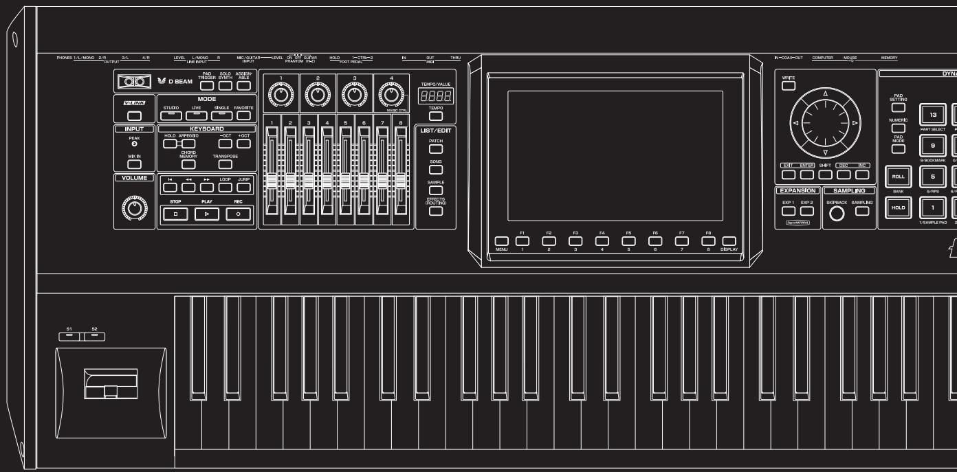
text_image
PROKES L/L MISO 2/R 3/L 4/R LEVEL L-MISO 5 MECUTAIN LEVEL 6 M.1.2 GRAV HOLD I-CTR=2 IN OUT TURI OUTPUT LINE INPUT INPUT PRANTOR PAC FOUR PIEDA IN V8 D BEAM SODS ASSIMANCE TEMPO VALUE MODE STUDIO LIVE SINGLE FAVORATE INPUT PEAK HOLD APPROXED 3OCT 4OCT CHORD GENDER TRANSPOSE MD IN VOLUME STOP PLAY REC LIST/EDIT PATCH DOYS SAMPLE CAPSIC (RDT/RDS) EXPANSION SAMPLING EXP 1 EXP 2 SKEEBACK SAMPLING HOLD 1 SAMPLE PAD 2 S1 SB WIFE TAB/SETTLE FLAVENIX 13 FAST SELECT 0 9 ROLL 5 B/SCHOOLER ON SANK 6-PDS 6-R F1 F2 F3 F4 F5 F6 F7 F8 DISPLAY MIN: 1 2 3 4 5 6 7 8Sound quality that's a class above
The Fantom-G features a new sound engine that provides a patch multi-effect (PFX) for each sound (patch) at all times, allowing you to create lavish sounds in a way not possible until now.
In addition, there are two multi-effects (MFX) processors that can be used flexibly. Up to twenty-two types of effects, such as chorus and reverb, can be used simultaneously.
Of course the “integration of audio and MIDI” featured on the Fantom-X is also provided, letting you use sampled sounds as internal sounds.
Mode settings optimized for your situation
The Fantom-G provides modes optimized for your situation; use "Live mode" for live performances, and "Studio mode" for music production.
"Live mode" lets you freely create eight-part multitimbral layers and splits. With functions such as Patch Remain, which ensures that the notes you were playing before switching sounds are not cut off, this mode is designed to ensure the expression and speed you need for a live performances.
"Studio mode" lets the Fantom-G operate as a 16-part multitimbral instrument, and allows you to use all of its effects in your music productions.
"Single mode" is what you'll want to choose when playing a single sound, such as when using the Fantom-G as a dedicated piano or organ. Choose this mode when you're editing a sound.
The latest and greatest internal sounds
Starting with the 88-note multisampled piano that was acclaimed on the Fantom-X, all sounds have been renewed. The Fantom-G boasts the world's best lineup of sounds, with an emphasis on quality. You'll have immediately usable sounds for performance and creativity in every situation. It features 256 MB of internal waveform capacity (double that of the Fantom-X series), with broad coverage of everything from acoustic sounds to synth sounds.
Support for the new ARX series expansion boards featuring the SuperNATURAL sound generator
The Fantom-G features two slots that support the ARX series, which not only allows you to expand the existing sounds, but provides an optimal sound engine for each different sound (Roland's new "SuperNATURAL" technology, which boasts amazing expressive power).
This new technology delivers the expressive power and quality of “the real thing,” surpassing even the high-quality internal sounds.
MEMO
“SuperNATURAL” is proprietary Roland technology that realistically expresses the tonal changes and performance techniques that are distinctive to acoustic instruments and electric instruments, bringing you natural and rich expressive power.
SuperNATURAL
New 152-track sequencer is a highly evolved fusion of audio and MIDI
The fusion of audio and MIDI has evolved to a new dimension. The new sequencer provides a graphical workflow with up to 128 tracks of MIDI and 24 tracks of audio available simultaneously. The easy to understand phrase-based interface lets you use a USB mouse for an even speedier music production environment.
Full-fledged sampler
The sampling functionality rivals dedicated samplers, offering not only detailed wave editing but also the ability to immediately play recorded samples from the pads or keyboard, or use them as material in audio tracks. Of course there's also an Auto Sync function, which lets you match the current tempo without changing the pitch, or change the pitch without affecting the tempo.
* 32 MB of sampling memory is provided as standard, and you can add DIMM memory (p. 312, p. 314) to expand this to a maximum of 1 GB.
Skip Back Sampling function
The Skip Back Sampling function, which was so popular on the Fantom-X series, is also provided on the Fantom-G. By constantly recording your performance on the Fantom-G, this function ensures that you can retroactively record an inspired improvisation at any time. Never again will you lose a great idea just because the recorder wasn't running.
Favorites function
This function gives you one-touch call-up of settings for the songs in your live performance.
Using this, you can simply press a single button to change sounds and settings during performances that require quick changes. Each such setting includes master volume, so you'll be able to prepare volume adjustments during your rehearsal to match the actual live performance environment.
Wide VGA color liquid crystal display
The large wide VGA color liquid crystal screen is a revolutionary leap that ensures superb visibility and operability in any situation.
A full range of interfaces
USB functionality has been enhanced. The USB MEMORY connector lets you use USB memory to back up your data. The USB MOUSE connector lets you connect a two-button wheel mouse for an even more ideal user interface. The USB COMPUTER connector handles data transfer between the Fantom-G and your computer, and also supports USB MIDI and audio. This lets the Fantom-G connect to various computer-based software tools, and also lets you use the dedicated editor software to perform editing tasks. In addition, the external audio inputs include dedicated LINE (STEREO) input jacks and a dedicated MIC/GUITAR jack.
V-LINK
V-LINK functionality opens up a new realm of expression for your performances because of the way it allows you to synchronize music and visual images. You can use controllers such as the D Beam and the Fantom-G's knobs, sliders, and dynamic pads to control visual images as part of the process of performing your music.
Plug-in editor/librarian
The included dedicated editor and librarian software let you use your computer to edit and manage the Fantom-G's sounds. The dedicated editor also supports operation as a VSTi/AU plug-in.
Support for GM/GM2
The Fantom-G supports GM/GM2. Any music data compatible with GM/GM2 (GM Scores) can be played by the Fantom-G.
Front Panel
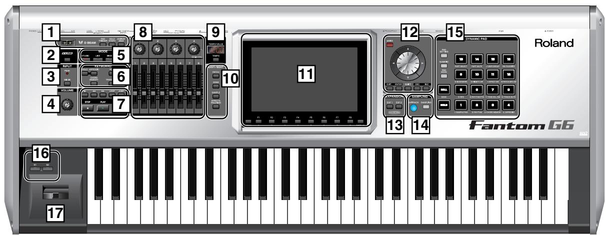
text_image
1 2 3 4 5 6 7 8 9 10 11 12 13 14 15 Roland Fantom 66 16 171 D BEAM
Here you can switch the D Beam function on/off. This lets you apply various effects to the sound by moving your hand above the sensor. → (p. 72)
[PAD TRIGGER]
This lets you use the D Beam controller to play the pads, as an alternative to striking them by hand. → (p. 73)
[SOLO SYNTH]
This lets you use the D Beam controller as a monophonic synthesizer. (p. 73)
* By holding down [SHIFT] and pressing the appropriate button, you can access the D Beam setting screen.
[ASSIGNABLE]
This lets you assign various parameters or functions to the D Beam controller, and use it to modify the sound in real time. (p. 75)
2 [V-LINK]
This switches V-LINK on/off. The V-LINK setting screen will appear when you turn this button on. → (p. 305)
3 INPUT
PEAK Indicator
This will light when the external input volume is too high.
[MIX IN]
This turns the external input on/off. → (p. 258)
* By holding down [SHIFT] and pressing this button you can access the input setting screen. → (p. 258)
4 VOLUME
VOLUME Knob
This adjusts the overall volume that is output from the rear panel OUTPUT A (MIX) jacks and PHONES jack. → (p. 28)
5 MODE
[STUDIO]
This puts the Fantom-G in Studio mode. Choose this setting for song production. (p. 66)
[LIVE]
This puts the Fantom-G in Live mode. Choose this setting when you want to play multiple sounds layered together or split across the keyboard. → (p. 58)
[SINGLE]
This puts the Fantom-G in Single mode. Choose this setting when you want to play a single sound at a time. (p. 46)
[FAVORITE]
This lets you register favorite sounds for immediate call-up — a convenient capability for live performances. → (p. 54)
6 KEYBOARD
[ARPEGGIO]
This turns the arpeggiator on/off. → (p. 78)
[HOLD]
This switches the arpeggiator's Hold function on/off. (p. 78)
[CHORD MEMORY]
This switches Chord Memory on/off. → (p. 81)
* By holding down [SHIFT] and pressing these buttons, you can access the setting screens for chord memory and the arpeggiator.
[-OCT], [+OCT]
These raise or lower the key range in one-octave steps. (-3- +3)
* By pressing the [-OCT] and [+OCT] buttons simultaneously you can reset the setting to its original value.
[TRANSPOSE]
If this is on, you can use [-OCT] [+OCT] to raise or lower the key range in semitone steps. (-5- +6)
* By pressing the [-OCT] and [+OCT] buttons simultaneously you can reset the setting to its original value.
7 SEQUENCER
Here you can perform sequencer operations such as playback and recording.
[◀]
This moves the song position to the beginning of the song. If you press this during playback, you will return to the beginning of the song and stop. → (p. 206)
[◀◀] [▶▶]
These move the song position to the first beat of the previous or next measure. (p. 206)
* By holding down [SHIFT] and pressing these buttons, you can move the song position to the previous or next marker.
[LOOP]
This turns Loop Playback on/off. → (p. 208)
* By holding down [SHIFT] and pressing this button, you can access the Loop setting screen.
[JUMP]
This jumps to the JUMP marker. If no marker has been set, it jumps to the beginning of the song. (p. 208)
* By holding down [SHIFT] and pressing this button, you can access the Marker setting screen.
[PLAY]
This plays back the song. → (p. 204)
It will blink in time with the tempo and time signature. (p. 297)
[STOP]
This stops playback.
[REC]
This accesses the Recording Standby screen. → (p. 222)
Pressing this during recording will activate the Rehearsal function. (p. 225)
8 CONTROL
Control Knobs 1-4
Control Sliders 1-8
These provide realtime control of the parameters or functions assigned to them. (p. 75)
* By holding down [SHIFT] and moving one of the above knobs (sliders), you can access the setting screen for that control. → (p. 76)
MAGIC CTRL (Magic Control)
Magic Control is a function that automatically changes the role of knob 4 and slider 8 according to the screen. For example, in the Patch List screen (p. 49), knob 4 selects the category and slider 8 scrolls the list.
9 TEMPO/VALUE
This indicates the tempo. When you move a control knob or slider, this will indicate its value.
[TEMPO]
You can adjust the tempo by pressing this button and turning the VALUE dial. → (p. 78, p. 207)
10 LIST/EDIT
[PATCH]
Press this to edit a patch. Press it once to access the Patch Zoom Edit screen (p. 84), or twice in succession to access the Patch Pro Edit screen (p. 86).
[SONG]
Press this to edit a song. Press it once to access the Song Play screen (p. 205), or twice in succession to access the Song Edit screen (p. 232).
[SAMPLE]
Press this to edit a sample. Press it once to access the Sample Edit screen (p. 266), or twice in succession to access the Sample List (p. 263).
[ EFFECTS (ROUTING)]
Press this to make effect-related settings. → (p. 150)
11 DISPLAY
A variety of information is shown here according to the operations you perform.
[MENU]
Opens the MENU. → (p. 280)
Function buttons ([F1]-[F8])
When you're editing, these buttons execute various functions that will differ depending on the screen.
[DISPLAY]
Displays the shortcut menu. (p. 44)
12 VALUE
[WRITE]
Writes the modified content into memory.
→ (p. 80, p. 82, p. 88, p. 116, p. 148, p. 254, p. 274, p. 290)
VALUE Dial
Modifies a value. By holding down [SHIFT] and turning the VALUE dial, you can modify the value in larger steps.
[CURSOR] Buttons
These move the cursor up/down/left/right.
[EXIT]
This returns you to the previous screen or closes an opened window. In some screens, it cancels the currently executing function.
[ENTER]
Use this to finalize a value or to execute an operation.
[DEC], [INC]
These modify a value. The value will change more rapidly if you hold down one button and press the other. If you hold down [SHIFT] while pressing these buttons, the value will change more rapidly.
[SHIFT]
This button is used in conjunction with other buttons to execute various functions.
13 EXPANSION
[EXP 1], [EXP 2]
These access the screens for expansion boards installed in the Fantom-G.
* For details on operation, refer to the owner's manual of the expansion board you've installed.
14 SAMPLING
[SKIPBACK]
This retroactively samples your performance for a specified period of time prior to when you pressed the button. → (p. 262)
[SAMPLING]
This accesses the Sampling menu screen. (p. 260)
15 DYNAMIC PAD
[PAD SETTING]
This accesses the setting and information screen for the currently selected Pad mode. → (p. 190)
[NUMERIC]
Lets you use the pads as numeric keys. (p. 41)
[PAD MODE]
Switches the pad mode. → (p. 188)
[ROLL]
Turns the Roll function on/off. → (p. 189)
Depending on the Pad mode, this will switch banks.
[HOLD]
Turns the Hold function (which causes the pad to continue sounding even after it's released) on/off. (p. 188)
[PAD 1-16]
You can use these to play sounds just like the keyboard. They will also perform various functions depending on the Pad mode. → (p. 188)
16 [S1] [S2] (Assignable Switches)
You can assign various parameters or functions to these buttons.
They will turn on/off the assigned parameter or function in real time to modify the sound. (p. 77)
* By holding down [SHIFT] and pressing one of the above buttons, you can access the corresponding setting screen. → (p. 77)
17 Pitch Bend/Modulation Lever
You can use this to modify the pitch or apply vibrato.
Rear Panel

text_image
1 Poland 3 4 5 6 7 n G8 91 POWER ON Switch
Press to turn the power on/off. → (p. 28)
2 AC Inlet
Connect the included power cord to this inlet.
3 USB
USB MEMORY Slot
A USB memory (sold separately) can be inserted here.
* Never insert or remove a USB memory while this unit's power is on. Doing so may corrupt the unit's data or the data on the USB memory.
* Carefully insert the USB memory all the way in—until it is firmly in place.
USB MOUSE Connector
Connect the USB mouse (sold separately). → (p. 26)
USB COMPUTER Connector
This connector lets you use a USB cable to connect your computer to the Fantom-G. → (p. 285)
4 DIGITAL AUDIO IN/OUT Connectors (S/P DIF COAXIAL)
These are coaxial-type S/P DIF format digital in/out connectors. These connectors input and output a digital audio signal (stereo). The output signal is identical to the signal that is output from the OUTPUT A (MIX) jacks.
* S/P DIF is a digital interface format used for consumer digital audio devices.
* If you switch off the power to an external device that is connected to the DIGITAL AUDIO IN jack or disconnect the cable, noise may subsequently be heard in the input from DIGITAL AUDIO IN. If this occurs, correctly reconnect the external device, or turn off the Fantom-G's [MIX IN] switch.
5 MIDI Connectors (IN, OUT, THRU)
These connectors can be connected to other MIDI devices to receive and transmit MIDI messages.
6 FOOT PEDAL
CTRL (CONTROL) 1, 2 Jacks
You can connect optional expression pedals (EV-5, etc.) or optional pedal switches (DP series etc.) to these jacks. By assigning a desired function to a pedal, you can use it to select or modify sound or perform various other control. → (p. 31)
* Use only the specified expression pedal (EV-5; sold separately). By connecting any other expression pedals, you risk causing malfunction and/or damage to the unit.
HOLD Jack
An optional pedal switch (DP series, FS-5U etc.) can be connected to this jack for use as a hold pedal. → (p. 31) This can also be set so it supports the use of half-pedaling techniques. So, after connecting an optional pedal switch (DP series etc.), you can employ pedal work to achieve even finer control in performances in which piano tones are used.
7 AUDIO INPUT
MIC/GUITAR Jack
You can connect either a mic or guitar. Set the Switch as appropriate for the device you've connected to the MIC/GUITAR jack.
| GUITAR (Hi-Z) | Guitar (High impedance supported) |
| PHANTOM OFF | Dynamic Mic: 1/4" phone plug (balanced or unbalanced), XLR connector |
| PHANTOM ON | Condenser Mic: XLR connector (48 V phantom power supported)* If you don't need phantom power supply, select the PHANTOM OFF position. |
* This instrument is equipped with balanced (XLR/TRS) type jacks. Wiring diagrams for these jacks are shown below. Make connections after first checking the wiring diagrams of other equipment you intend to connect.
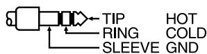


Connect a line-level device such as an audio device (e.g., portable music player) or keyboard. If you want to use mono input, connect to the L jack (p. 258).
LINE LEVEL knob
Controls the volume of the line input.

8 OUTPUT
OUTPUT A (MIX) Jacks (L (MONO), R)
These jacks output the audio signal to the connected mixer/amplifier system in stereo. For mono output, use the L jack. → (p. 26)
OUTPUT B Jacks (L, R)
These jacks output the audio signal to the connected mixer/amplifier system in stereo.
INDIVIDUAL 1-4 Jacks
These jacks output audio signals in mono to an amp or mixer.
* The setting determining whether these jacks are used as stereo OUTPUT jacks or monaural INDIVIDUAL jacks is made with the Output Assign setting. → (p. 152)
9 PHONES Jack
This is the jack for connecting headphones (sold separately). (p. 26)
Connecting an Amp and Speaker System
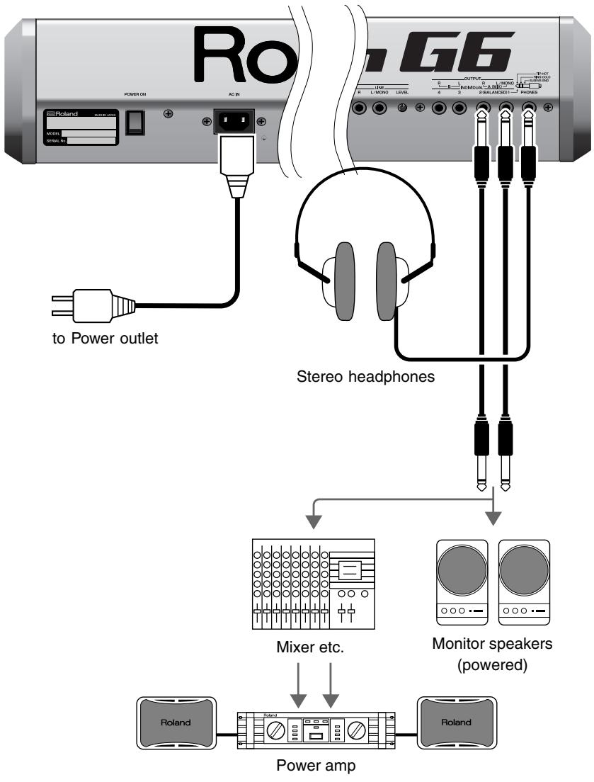
Since the Fantom-G contains no amplifier or speakers, you'll need to connect it to audio equipment such as a keyboard amplifier, monitor speaker system or home stereo, or use headphones to hear its sound.
- Before hooking anything up, make sure that the power on all of your gear is turned OFF.
- Connect one end of the supplied power cable to the Fantom-G, and the other end to a power outlet.
- Connect the Fantom-G to your amp/speaker system as shown in the diagram.
flowchart
graph TD
    A["RoG6"] -->|to Power outlet| B["+"]
    C["+"] --> D["+"]
    E["+"] --> F["+"]
    G["+"] --> H["+"]
    I["+"] --> J["+"]
    K["+"] --> L["+"]
    M["+"] --> N["+"]
    O["+"] --> P["+"]
    Q["+"] --> R["+"]
    S["+"] --> T["+"]
    U["+"] --> V["+"]
    W["+"] --> X["+"]
    Y["+"] --> Z["+"]
    AA["+"] --> AB["+"]
    AC["+"] --> AD["+"]
    AE["+"] --> AF["+"]
    AG["+"] --> AH["+"]
    AI["+"] --> AJ["+"]
    AK["+"] --> AL["+"]
    AM["+"] --> AN["+"]
    AO["+"] --> AP["+"]
    AQ["+"] --> AR["+"]
    AS["+"] --> AT["+"]
    AU["+"] --> AV["+"]
    AW["+"] --> AX["+"]
    AY["+"] --> AZ["+"]
    BA["+"] --> BB["+"] --> BC["+"] --> BD["+"] --> BE["+"] --> BF["+"] --> BG["+"] --> BH["+"] --> BI["+"] --> BJ["+"] --> BK["+"] --> BL["+"] --> BM["+"] --> BN["+"] --> BO["+"] --> BP["+"] --> BPb["+"] --> BPc
    BB --> BA
    BC --> BB
    BD --> BC
    BE --> BC
    BF --> BC
    BG --> BC
    BH --> BC
    BI --> BC
    BJ --> BC
    BK --> BC
    BL --> BC
    BM --> BC

To prevent malfunction and/or damage to speakers or other devices, always turn down the volume, and turn off the power on all devices before making any connections.

In order to fully experience the Fantom-G's sound, we recommend using a stereo amp/speaker system. If you're using a mono system, however, make your connections to the Fantom-G's OUTPUT A (MIX) jack L (MONO).

Audio cables are not included with the Fantom-G. You'll need to provide them.

For details on how to install a Expansion Board (sold separately), refer to “Installing the Expansion Board” (p. 308, p. 310).

The OUTPUT A [MIX] jacks support balanced output. Use a correctly wired cable so that the HOT, COLD, and GND as printed on the rear panel of the Fantom-G are correct for the mixer or other input device you're using.
Connecting a USB Mouse (sold separately)
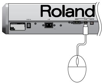
If you connect a commercially available USB mouse to the Fantom-G's rear panel USB MOUSE connector, a mouse cursor will be shown in the display, and you'll be able to use the mouse.
text_image
Roland| Action | Operation |
| Left-click | Select (move the cursor) |
| Right-click | [ENTER] button / list display |
| Wheel | VALUE dial / scroll |
| Drag (move while holding down left button) | Drag the mouse on the area or knob for which you want to input a value. Dragging upward or to the right will increase the value, and dragging downward or to the left will decrease it. 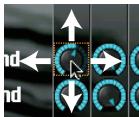 |
| Click the button | Opens the menu (p. 280) |
| Click the button | [EXIT] button |
| Click the button | Opens the shortcut menu (p. 44) |
Placing the Fantom-G on a Stand
* Be careful not to pinch your fingers when setting up the stand.
For Fantom-G6/G7 user
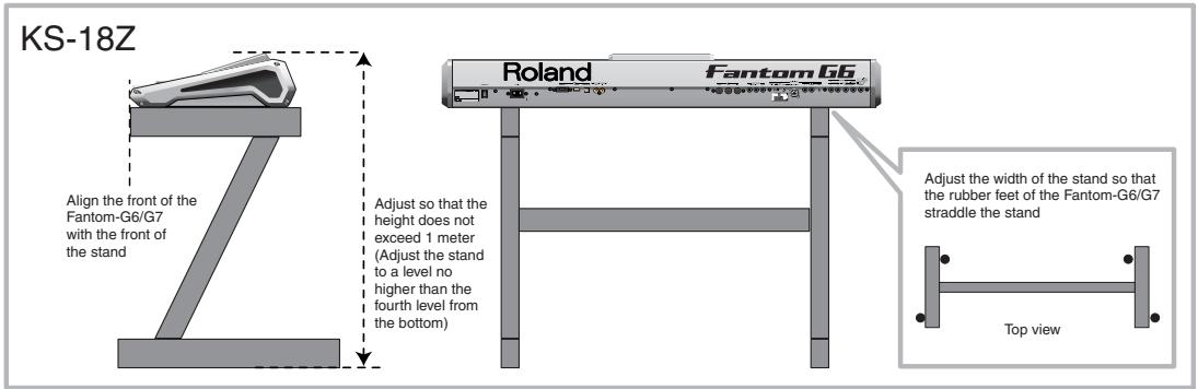
If you want to place the Fantom-G6/G7 on a stand, use the Roland KS-18Z. Place the instrument on the stand as follows.
text_image
KS-18Z Align the front of the Fantom-G6/G7 with the front of the stand Adjust so that the height does not exceed 1 meter (Adjust the stand to a level no higher than the fourth level from the bottom) Roland Fantom G6 Top view Adjust the width of the stand so that the rubber feet of the Fantom-G6/G7 straddle the stand
WARNING:
Use of stand not according to the instructions above will result in instability causing possible injury.
For Fantom-G8 user
If you want to place the Fantom-G8 on a stand, use the Roland KS-18Z or KS-G8. Place the instrument on the stand as follows.
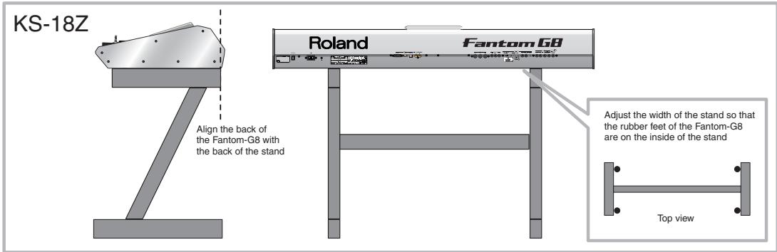
text_image
KS-18Z Roland Fantom G8 Align the back of the Fantom-G8 with the back of the stand Adjust the width of the stand so that the rubber feet of the Fantom-G8 are on the inside of the stand Top view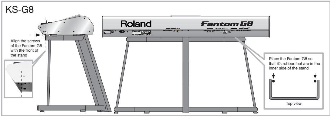
text_image
KS-G8 Roland Fantom G8 Align the screws of the Fantom-G8 with the front of the stand Place the Fantom-G8 so that it's rubber feet are in the inner side of the stand Top view
WARNING:
Use of stand not according to the instructions above will result in instability causing possible injury.
Turning On the Power
Once the connections have been completed (p. 25), turn on power to your various devices in the order specified. By turning on devices in the wrong order, you risk causing malfunction and/or damage to speakers and other devices.
-
Before turning on the Fantom's power, consider these two questions:
-
Are all peripheral devices connected correctly?
-
Have the volume controls of the Fantom-G and all connected audio devices been turned to their lowest settings?
-
Turn on the POWER ON switch located on the rear panel of the Fantom-G.
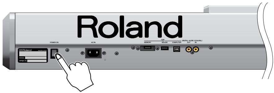
text_image
Roland POWER ON AC IN MEMORY USB COMPUTER (HTML AUDIO CONTROL) + - + + + + + + + + + + + + + + + + + + + + + + + + + + + + + + + + + + + + + + + + + + + + + + + + + + + + + + + + + + + + + + + + + + + + + + + + + + + + + + + + + + + + + + + + + + + + + + + + + + + + + + + + + + + + + + + + + + + + + + + + + + + + + + + + + + + + + + + + + + + + + + + + + + + + + + + + + + + + + + + + + + + + + + + + + + / - Poland - Mio. - mio. - mio. in.* This unit is equipped with a protection circuit. A brief interval (a few seconds) after power up is required before the unit will operate normally.
- Turn on the power for any connected amplifiers or speakers.
- Play the Fantom-G's keyboard, gradually increasing the setting of its volume control, and then carefully raise the volume of your connected amplifiers or speakers to the desired listening level.
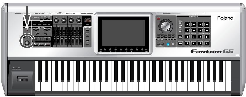
text_image
Roland Fantom 66
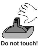
To ensure proper operation of the pitch bend lever, make sure not to touch the lever when turning the Fantom-G's power on.

Be careful not to set your listening volume too high to avoid damage to your amp/speaker system or your hearing.
Turning Off the Power
-
Before you turn off the power, consider these two questions:
-
Have the volume controls for the Fantom-G and all connected audio devices been turned to their lowest settings?
-
Have you saved your Fantom-G sounds or other data you've created?
-
Turn off the power for all connected audio devices.
-
Turn off the POWER ON switch of the Fantom-G.

If you need to turn off the power completely, first turn off the POWER switch, then unplug the power cord from the power outlet. Refer to "Power Supply" (p. 7).
Listening to the Demo Songs
The Fantom-G has a demo song that will be loaded at start-up.
Here's how to play the demo.
1. Press [PLAY].
The demo song will play.
![ROLAND FANTOM G8 - Press [PLAY]. - 1](/content/2025/01/130804/images/6064d569157a704e555ed19b76992c0ca0c8c1cfd3947bd2289e4c0ac96d87b1.jpg)
text_image
Roland Fantom 662. Press [STOP] to stop demo song playback.
![ROLAND FANTOM G8 - Press [STOP] to stop demo song playback. - 1](/content/2025/01/130804/images/b944d1bd730bb498eb6e35aff36f87d5f0ce97ee492f2157f2598b1aab6e0511.jpg)
text_image
Roland Fantom 6GSong Automatically Loaded at Power-on (When Loading a Project)
When the Fantom-G is powered-on (when loading a project), song 001 (the top song in the Song List) will be loaded automatically.

If you don't want a song to be loaded automatically at power-on (when loading a project), delete song 001 as described in “Deleting a Song File (Song Delete)” (p. 210).

When you execute a Factory Reset (p. 284), the demo song will be written to song 001.

All rights reserved.
Unauthorized use of this material for purposes other than private, personal enjoyment is a violation of applicable laws.
Velocity/Aftertouch
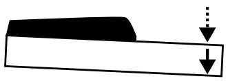
The force with which you play the keyboard, or the “velocity” with which you play, can affect the volume or timbre of a sound. Aftertouch—downward pressure you apply to a key after playing a note—can also affect the sound.
Pitch Bend/Modulation Lever
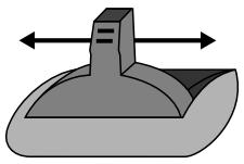
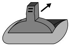
While playing the keyboard, move the lever to the left to lower the pitch of the currently selected patch, or to the right to raise its pitch. This is known as pitch bend. You can also apply vibrato by gently pushing the lever away from you. This is known as modulation.
If you push the lever away from you and at the same time move it to the right or left, you can apply both effects at once.
Pitch Bend
Modulation
Octave Shift (OCT)
You can shift the pitch of the keyboard in one-octave units over a range of +/-3 octaves.
Use KEYBOARD [-OCT] or [+OCT] at the left of the screen to make the desired setting.
To return to the original setting, press both buttons simultaneously.
Transpose
You can transpose the pitch of the keyboard in semitone units (-5- +6).
At the left of the display, turn on the KEYBOARD [TRANSPOSE] button, and then use the [-OCT] or [+OCT] button to specify the desired transposition.
To return to the original setting, press both buttons simultaneously.

For details on the setting, refer to p. 292.

There are two types of
aftertouch: Polyphonic
Aftertouch, which applies aftertouch to individual notes, and Channel Aftertouch,
which applies aftertouch to an entire MIDI channel (p. 251).
The Fantom-G can output the MIDI data for Polyphonic
Aftertouch using the pads, and Channel Aftertouch using the keyboard.

You can set the amount of pitch change for each patch (p. 96).
Hold Pedal
If an optional pedal switch (DP series) is connected to the rear panel PEDAL HOLD jack, you can press the pedal switch to cause notes to sustain or "hold" even after their keys have been released.
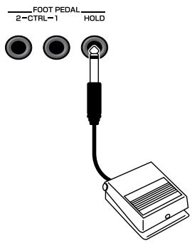
text_image
FOOT PEDAL 2-CTRL-1 HOLDControl Pedal
If an optional expression pedal or pedal switch (EV-5, DP series.) is connected to the rear panel PEDAL CONTROL jack (1, 2), you can use the pedal to control the volume or various functions.
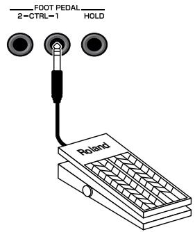
text_image
FOOT PEDAL 2-CTRL-1 HOLD Roland
For details on the setting, refer to p. 291.

The way in which the sound changes will depend on the settings. For details on settings for parameters controlled by the pedal, refer to “Making Control Pedal Settings” (p. 77).

Use only the specified expression pedal or pedal switch (EV-5, DP series, BOSS FS-5U; sold separately). By connecting any other expression pedals, you risk causing malfunction and/or damage to the unit.
How the Fantom-G is Organized
Basic Structure
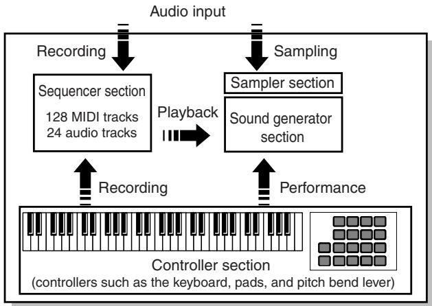
Broadly speaking, the Fantom-G consists of a controller section, sound generator section, sequencer section, and sampler section.
flowchart
graph TD
    A["Audio input"] --> B["Recording"]
    B --> C["Sequencer section 128 MIDI tracks 24 audio tracks"]
    D["Sampling"] --> E["Sampler section"]
    E --> F["Sound generator section"]
    G["Performance"] --> H["Controller section (controllers such as the keyboard, pads, and pitch bend lever)"]
    C --> I["Playback"]
    F --> I
    H --> I
    I --> J["Recording"]
    J --> K["Controller section"]
Controller section
This section includes the keyboard, pads, pitch bend / modulation lever, the panel knobs, sliders, and D Beam controller, and pedals connected to the rear panel.
Sound generator section
This section generates sound in response to performance data from the controller section or sequencer section.
Sequencer section
This is a sequencer with 128 MIDI tracks and 24 audio tracks. The MIDI tracks record performance data (MIDI) from the keyboard, pads, and other controllers. The audio tracks record sound (audio) from a mic or guitar connected to the Fantom-G's audio input jacks.
Sampler section
A sampler is a device that captures (samples) sound from a CD player or mic connected to the audio input or digital input, and saves this sample as a wave file.
A captured sample can be used in the same way as the waveforms of the sound generator section. You can also sample the sound of the internal sound generator section itself (p. 258).
The Fantom-G can load WAV/AIFF format wave files from your computer via USB as samples.
Different Units of Sound
When using the Fantom-G, you'll encounter various units of sound. Here we'll provide a simple explanation of these units.
Tone
A Tone is the smallest unit of sound in the Fantom-G. However, you can't play a tone by itself. The smallest unit of sound that you can play is the "Patch," so you can think of tones as the sonic material that makes up each patch.
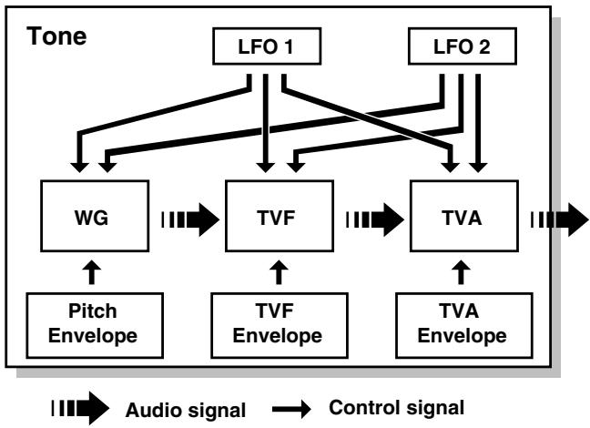
flowchart
graph TD
    A["LFO 1"] --> B["WG"]
    C["LFO 2"] --> D["TVF"]
    B --> E["Pitch Envelope"]
    D --> F["TVF Envelope"]
    D --> G["TVA Envelope"]
    B --> H["↓"]
    D --> I["↓"]
    G --> J["↓"]
    style A fill:#f9f,stroke:#333
    style C fill:#f9f,stroke:#333
    style B fill:#ccf,stroke:#333
    style D fill:#ccf,stroke:#333
    style G fill:#ccf,stroke:#333
    linkStyle 0 stroke:#000,stroke-width:2px
    linkStyle 1 stroke:#000,stroke-width:2px
    linkStyle 2 stroke:#000,stroke-width:2px
    linkStyle 3 stroke:#000,stroke-width:2px
    linkStyle 4 stroke:#000,stroke-width:2px
    linkStyle 5 stroke:#000,stroke-width:2px
    linkStyle 6 stroke:#000,stroke-width:2px
    linkStyle 7 stroke:#000,stroke-width:2px
    linkStyle 8 stroke:#000,stroke-width:2px
    linkStyle 9 stroke:#000,stroke-width:2px
    linkStyle 10 stroke:#000,stroke-width:2px
A tone consists of the following five elements.
WG (Wave Generator)
This selects the PCM waveform (wave) that is the basis of the sound, and specifies how its pitch will change.
All of the patches built into the Fantom-G consist of combinations of tones that are based on PCM waveforms (waves).
NOTE
A rhythm tone (percussion instrument sound) contains four wave generators.
This specifies how the frequency components of the sound will change over time.
TVA (Time Variant Amplifier)
This specifies volume change and panning.
Envelope
An envelope specifies a change over time. Dedicated envelopes are provided for Pitch, TVF (filter), and TVA (volume). For example, if you want to modify the time over which the sound starts or decays, you would use the TVA Envelope settings to specify the desired time-variant volume change.
LFO (Low Frequency Oscillator)
An LFO creates cyclic change (modulation). There are two LFOs, and each can be applied to one aspect of the sound; WG (pitch), TVF (filter), or TVA (volume). Applying an LFO to the WG pitch will produce vibrato, applying it to the TVF cutoff frequency will produce wah, and applying it to the TVA volume will produce tremolo.
NOTE
A rhythm tone (percussion instrument sound) does not have an LFO.
Patch
Patches are the basic unit of sound on the Fantom-G; they correspond to an individual instrument such as “piano,” “organ,” or “guitar.” A patch can consist of up to four tones. The Structure 1&2 and 3&4 parameters (p. 92) determine how the four tones are combined. You can apply a “PFX (Patch MFX)” effect to each patch.
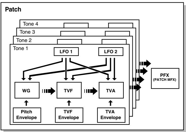
flowchart
graph TD
    A["Tone 1"] --> B["WG"]
    A --> C["TVF"]
    A --> D["TVA"]
    E["Tone 2"] --> F["LFO 1"]
    E --> G["LFO 2"]
    H["Tone 3"] --> I["..."]
    J["Tone 4"] --> K["..."]
    L["Pitch Envelope"] --> A
    M["TVF Envelope"] --> A
    N["TVA Envelope"] --> A
    O["PFX (PATCH MFX)"] --> P["..."]
    Q["->"] --> R["->"]
    S["->"] --> T["->"]
    U["->"] --> V["->"]
    W["->"] --> X["->"]
    Y["->"] --> Z["->"]
    AA["->"] --> AB["->"]
    AC["->"] --> AD["->"]
    AE["->"] --> AF["->"]
Rhythm set
A rhythm set is a group of percussion instrument sounds. Since percussion instrument sounds are not usually used to play melodies, there's no need for them to produce different pitches when played from the keyboard. Rather, it's important that you have simultaneous access to as many percussion instrument sounds as possible. This is why in a rhythm set, each note (note number) of the keyboard will play a different percussion instrument sound. You can apply a "PFX (Patch MFX)" effect to each rhythm set.
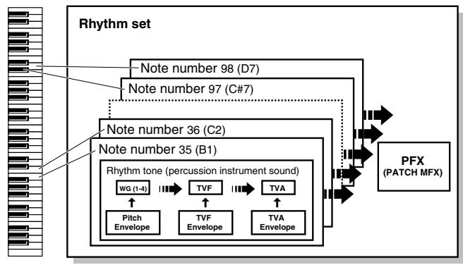
flowchart
graph TD
    A["Rhythm set"] --> B["Note number 98 (D7)"]
    A --> C["Note number 97 (C#7)"]
    A --> D["Note number 36 (C2)"]
    A --> E["Note number 35 (B1)"]
    D --> F["Rhythm tone (percussion instrument sound)"]
    E --> F
    F --> G["WG (1-4)"]
    F --> H["TVF"]
    F --> I["TVA"]
    G --> J["Pitch Envelope"]
    H --> K["TVF Envelope"]
    I --> L["TVA Envelope"]
    F --> M["PFX (PATCH MFX)"]
    M --> N["Output"]
Sample set
On the Fantom-G, a piece of wave data obtained by audio recording or sampling is called a Sample. A sample set is a collection of sixteen samples handled as a set. You can specify how each sample will play when you press a pad or key.
Single / Live / Studio Modes
The Fantom-G can operate in the following three modes.
Single mode
Single mode is when you play a single patch (or rhythm set or sample set), using the Fantom-G as a single piano, organ, etc. Choose this mode when you want to edit a patch to create your own original sound.
Live mode
Live mode is designed for live performance. It lets you play up to eight patches (or either rhythm sets or sample sets) simultaneously. For example, you can create layers (p. 62) in which a piano sound and strings sound are heard simultaneously, or splits (p. 62) in which your right hand plays a piano sound while your left hand plays a bass sound.
Live set
Settings for Live mode can be saved as a "live set."
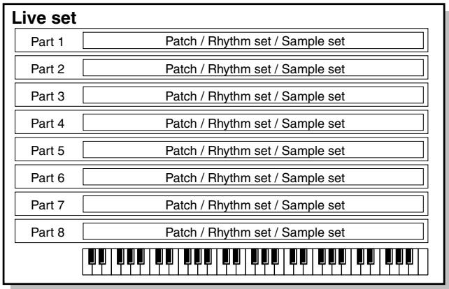
text_image
Live set Part 1 Patch / Rhythm set / Sample set Part 2 Patch / Rhythm set / Sample set Part 3 Patch / Rhythm set / Sample set Part 4 Patch / Rhythm set / Sample set Part 5 Patch / Rhythm set / Sample set Part 6 Patch / Rhythm set / Sample set Part 7 Patch / Rhythm set / Sample set Part 8 Patch / Rhythm set / Sample setStudio mode
Studio mode is designed to let you record a song. It provides sixteen parts, and you can assign a patch (or rhythm set or sample set) to each part, letting you use sixteen different sounds at the same time. You can use the mixer screen to adjust the level and pan for each of the sixteen parts.
Studio set
Settings for Studio mode can be saved as a "studio set."
Studio set
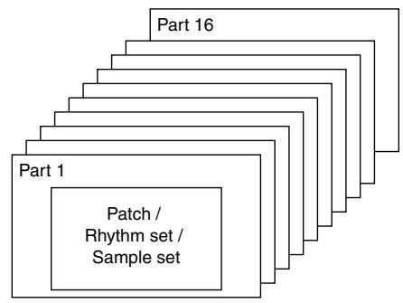
text_image
Part 1 Patch / Rhythm set / Sample set Part 16Part
On the Fantom-G, a "Part" is a kind of location or slot to which you can assign a patch, rhythm set, or sample set.
Live mode gives you eight parts, and you can assign a patch, rhythm set, or sample set to each part. This means that you can play up to eight sounds together.
Studio mode gives you sixteen parts, and you can assign a patch, rhythm set, or sample set to each part.
Part group
In addition to the internal parts (the internal sound generator), the Fantom-G provides part groups for expansion boards 1 and 2, and for the external MIDI output.
| Part group | Explanation | Number of parts |
| Internal | Internal (internal sound generator) | Live mode: 8 Studio mode: 16 |
| EXP 1 | Expansion board 1 | Up to 16* Depends on the expansion board |
| EXP 2 | Expansion board 2 | Up to 16* Depends on the expansion board |
| External | External MIDI output | 16 |
About Polyphony
The Fantom-G has a maximum polyphony of 128 simultaneous notes. Here we'll explain how the polyphony is counted, and what happens when the limit of 128 notes is exceeded.
How polyphony is counted
The Fantom-G can produce up to 128 notes simultaneously. This number of notes will vary depending not only on the number of notes you're actually playing, but also on the number of tones used by each patch, and the number of waves used by each tone. When playing a patch, the polyphony is calculated as follows.
(number of patches that are sounding) x (number of tones used in the currently sounding patches) x (number of waves used by those tones). For example, if a patch consists of four tones, and each of these tones uses two waves, it will use a total of eight notes of polyphony. If you're playing in Live mode (multi) or in Studio mode, count the polyphony for each part to obtain the total polyphony of all parts.
* If you're using realtime time stretch, twice as much polyphony will be used.
Patch polyphony
If you attempt to play more than 128 notes simultaneously on the Fantom-G, existing notes will be turned off, starting with the note having the lowest priority of the currently sounding notes. This priority is specified by the Patch Priority setting (p. 90).
You can choose either "LAST" or "LOUDEST" as the patch priority. If you choose "LAST," notes will be turned off starting with the first-played of the currently sounding notes when you exceed the 128 note limit. If you choose "LOUDEST," notes will be turned off starting with the note whose volume is least. Normally, you will probably want to select "LAST."
If you're using multiple patches to play an ensemble, it's important to specify which part gets priority for its notes over the others. This is specified by the Voice Reserve setting (p. 141). The patch priority setting (p. 90) will determine how the notes of a patch are turned off.
Voice reserve
The Fantom-G provides a Voice Reserve setting, which lets you reserve a minimum number of notes for each part. For example, if you specify a voice reserve setting of "10" for part 16, ten notes of polyphony will be guaranteed to be available for the sound being played by part 16 even when the overall Fantom-G reaches its 128 note limit. When making voice reserve settings, you'll need to consider the number of notes you actually want to play and the number of tones in the patches you're using (p. 141).
MEMO
You can make voice reserve settings for up to a total of 64 notes for all parts.
NOTE
When the audio tracks of a song are playing back, the audio tracks take priority over the voice reserve settings.
About Memory

flowchart
graph TD
    A["Fantom-G"] --> B["Internal memory (50 MB)"]
    B --> C["Project"]
    C --> D["USB storage"]
    D --> E["Factory data"]
    E --> F["Temporary area"]
    F --> G["Project (overwritable)"]
    G --> H["Sequencer"]
    G --> I["Samples"]
    G --> J["Sounds"]
    H --> K["2000 phrases"]
    H --> L["50 songs"]
    H --> M["64 RPS sets"]
    H --> N["64 rhythm pattern sets"]
    I --> O["Expandable to 1 GB with DIMM memory (sold separately)"]
    J --> P["Patches USER: 512"]
    J --> Q["Live sets USER: 512"]
    J --> R["Studio sets USER: 128"]
    J --> S["Rhythm sets USER: 64"]
    J --> T["Sample sets 128"]
    G --> U["System"]
    U --> V["System"]
    V --> W["USB memory (sold separately)"]
    W --> X["Project"]
    X --> Y["Expansion boards (sold separately)"]
    Y --> Z["EXP 1"]
    Y --> AA["EXP 2"]
    Y --> AB["Select"]
    AC["Load"] --> AD["Save"]
    AD --> AE["Fantom-G"]
    AF["Factory reset"] --> AG["Factory data"]
    AG --> AH["Temporary area"]
Project
The largest unit of memory handled by the Fantom-G is the “project.” As shown in the illustration, a project contains sequencer data, samples, sounds, and various system settings. On the Fantom-G you can use one project at a time.
Preset data
This is read-only data for patches, live sets, studio sets, rhythm sets, and waves.
Internal memory
The Fantom-G has internal memory in which you can save a project. A project can be overwritten at will. You can also restore the memory to the factory-set condition (Factory Reset) (p. 284).
The internal memory is approximately 50 MB in size. If you need to save a project that is larger than 50 MB, you'll need to save it on USB memory.
Temporary area
When you switch on the Fantom-G's power or load a project, the project data is placed in an area of memory called the “temporary area.”
When you edit a patch or song, you are modifying the data in this temporary area.
These edits will be lost if you simply turn off the power; if you want to keep the changes you made, you must save them (SAVE/WRITE).
DIMM memory (sold separately)
You can install up to 1 GB of DIMM memory. Installing DIMM memory will allow you to record or sample for a longer period of time. For details on installing DIMM, refer to “Expanding the DIMM Memory” (p. 312, p. 314).
USB memory (sold separately)
Internal memory can hold only one project, but commercially available USB memory can hold multiple projects. Connect your USB memory to the rear panel USB MEMORY connector (p. 24). For details on how to format USB memory, refer to p. 284.
* If the USB memory is formatted using something other than FAT, it will not be recognized by the Fantom-G. Use your computer to format the USB memory with the "FAT" or "FAT32" file system. (If you're using Mac OS X, format the USB memory using the "MS-DOS file system (FAT32).")
USB storage
You can use a USB cable to connect the Fantom-G to your hard disk, and save (back up) projects from internal memory or USB memory to the hard disk of your computer (p. 285).
Samples created using the Fantom-G can also be used by software on your computer; or conversely, you can use your computer software to create wave data and use it as samples in the Fantom-G.
Factory data
The factory data is memory that holds the factory-set state of the internal memory. If you have deleted the factory-set patches or other data from internal memory, and would like to use this data again, you can execute the Factory Reset operation (p. 284).
* If you've created important data and saved it in the Fantom-G's internal memory, be aware that your data will be lost if you execute a Factory Reset. (The data you're in the process of editing will also be lost.)
Expansion boards (ARX series; sold separately)
Up to two expansion boards (ARX series; sold separately) can be installed in the Fantom-G. An expansion board includes a sound generator engine, and will expand both the number of available sounds and the polyphony. For details on installing expansion boards, refer to “Installing the Expansion Board” (p. 308, p. 310).
About the Internal Effects
Types of Effects
The Fantom-G contains the following effects units. You can make settings independently for each one.
PFX (Patch MFX) (Patch multi-effect)
This is a dedicated multi-effect unit for the patch. You can use it as part of the sound of the patch itself.
You can choose from 76 types including distortion and rotary.
MFX (Multi-effect)
This is a general-purpose multi-effect that can apply various modifications to the sound.
You can choose from 78 types including distortion and rotary.
Chorus
Chorus is an effect that adds depth and spaciousness to the sound. You can choose whether to use this as chorus or as delay.
Reverb
Reverb is an effect that simulates the reverberation that characterizes sounds heard in a hall or other acoustic environment. You can choose from 10 types of reverb.
Mastering effect
This is a stereo compressor (limiter) applied to the final output of the Fantom-G. It operates independently for high, mid, and low frequency bands, compressing sounds that exceed the specified volume level, and making the overall sound more consistent.
Input effect
This is a dedicated effect for the external input.
You can choose from six types, including equalizer and compressor.
About the Sequencer
Audio and MIDI
The Fantom-G's sequencer can record audio and MIDI.
Audio (samples)
Audio is a “recording” of the sound from a mic or portable audio player connected to the Fantom-G’s input jacks. The recorded audio data is called a “sample.” You can create a song simply by placing samples in an audio track.
MIDI (phrases)
MIDI records performance data from the keyboard or pads. The recorded MIDI data is called a “phrase.” You can create a song simply by placing phrases in a MIDI track.
In the sense that both types of recording can be used to capture a performance, MIDI is similar to audio, but while audio recording captures the “sound” of a performance, MIDI recording captures the notes and other control data of a performance, and allows you to freely make detailed edits even to the individual note data.
What is a Song?
Performance data for one composition is called a "song." This consists of audio tracks 1–24, MIDI tracks 1–128, a tempo track, and a beat track.
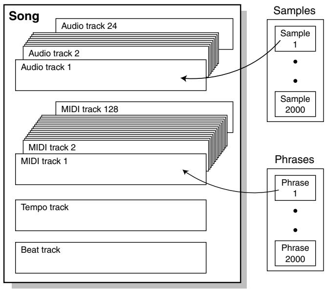
flowchart
graph TD
    A["Song"] --> B["Audio track 24"]
    A --> C["Audio track 2"]
    A --> D["Audio track 1"]
    A --> E["MIDI track 128"]
    A --> F["MIDI track 2"]
    A --> G["MIDI track 1"]
    A --> H["Tempo track"]
    A --> I["Beat track"]

    J["Samples"] --> K["Sample 1"]
    K --> L["•"]
    K --> M["•"]
    K --> N["Sample 2000"]

    O["Phrases"] --> P["Phrase 1"]
    P --> Q["•"]
    P --> R["•"]
    P --> S["Phrase 2000"]
What is a Track?
A track is an area in which performance data can be recorded.
Audio tracks 1-24
There are twenty-four tracks for recording audio.
Samples
A piece of recorded audio data is called a “sample.” You can create up to 2,000 samples in one project. The Fantom-G can capture samples by sampling (p. 258), or by importing WAV/AIFF format wave files via USB from your computer (p. 287). You can also create a song by placing samples in an audio track.
Samples also support the Sample Pad function (p. 191) which lets you play samples simply by pressing a pad.
MIDI tracks 1-128
There are 128 MIDI tracks that can record MIDI performances. A MIDI track can be assigned to the Fantom-G's 16 parts (Studio mode), to the two sets of up to 16 parts for the expansion boards (the number of parts will depend on the expansion board), or to the 16 parts of the external MIDI connector. You can also assign multiple tracks to a single part (for example, tracks 1 and 2 could be assigned to the Fantom-G's part 1.)
Phrases
The MIDI data recorded in a MIDI track is called a “phrase.” Up to 2,000 phrases can be created in a single project. Just like a track, each phrase can record a performance of 16 MIDI channels. You can also create a song simply by placing phrases in a MIDI track.
Phrases also support the RPS function that lets you instantly play a phrase simply by pressing a pad (p. 194), and the Rhythm Pattern function that lets you play rhythm patterns by pressing a pad (p. 196). This means that you can use phrases to record performance data for use in a live performance.
You can also use phrases to record your musical ideas.
Tempo track
The tempo track records tempo changes for the song. Use it when you want the tempo to change during the song. If the tempo is going to stay the same from the beginning to the end of the song, you can ignore the tempo track.
When you record a song on the Fantom-G, the tempo you specify at the time of recording is stored at the beginning of the tempo track.
This means that this tempo will always be used every time you play back the song.
In this way, songs are played back according to the data in their tempo track, but if you change the tempo during playback, the overall tempo of the entire song will change accordingly.
Beat track
The beat track records time signature information for each measure of the song. You'll make beat track settings when recording a new song, or when you want the time signature to change during the song.
Songs and the State of the Sound Generator
The Fantom-G's sequencer is available at all times, regardless of the sound generator mode (Single, Live, or Studio).
In Studio mode, you can record separate performances for each part using up to sixteen sounds. This makes Studio mode the ideal choice when you want to record or play back a song using an ensemble of multiple instruments such as drums, bass, and piano.
SMF (Standard MIDI File .MID)
SMF (Standard MIDI File) is a file format that allows performance data to be exchanged between music applications. Songs created on the Fantom-G can be saved as standard MIDI files (p. 256). The Fantom-G can also play back commercially available music data that is compatible with the GM/GM2 system (GM Scores).
About the Sampling Section
The sampling section “samples” (records) audio input from an external source such as an audio device or mic. You can play these sampled sounds as a patch or rhythm set. You can also import WAV/AIFF format files and use them in the same way.
Samples
A “sample” refers to a waveform (wave) produced by sampling on the Fantom-G. A sample consists of waveform data together with parameters such as a start point, loop start, and loop end. The Fantom-G can hold up to 2,000 samples for a single project.
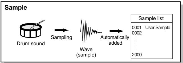
flowchart
graph LR
    A["Drum sound"] -->|Sampling| B["Wave (sample)"]
    B -->|Automatically added| C["User Sample"]
Switching the Sound Generator Mode
The Fantom-G provides three sound generator modes: Single, Live, and Studio. You can switch to the sound generator mode that's most appropriate for the way you're using the Fantom-G.
Single mode
This mode is for playing one sound (patch, rhythm set, sample set) at a time.
< To select Single mode >
1. Press [SINGLE].
![ROLAND FANTOM G8 - Press [SINGLE]. - 1](/content/2025/01/130804/images/d9a0bbb089c50c0d51de3e0cb7bd0a7080d6b1e544cbddceaa7a14819c66f35b.jpg)
text_image
MODE STUDIO LIVE SINGLE FAVORITE![ROLAND FANTOM G8 - Press [SINGLE]. - 2](/content/2025/01/130804/images/3796592b66858321cbb2e92c660c14ba7af607cd3955593bb14bb82b348a1082.jpg)
text_image
Single Play MyBlock Package Part 1 Patch FAST Piano AC Piano OFF 0001:G-Grand Tone Switch Dynamic Pad Part 7 Sample SAMPLE PRO USER 001:INITIAL SAMPLE 1 2 3 4 5 6 7 8 Patch Number Name: 0001GS-29 vkt F1 F2 F3 F4 F5 F6 F7 F8 Patch List F9 Part View Control PFX User Group Patch Edit Tone Sw/Sel![ROLAND FANTOM G8 - Press [SINGLE]. - 3](/content/2025/01/130804/images/ef4596465f0f20f715317c09f7bcb114d5505599d24cd788844553781c23f2df.jpg)
"Playing in Single Mode" (p. 46)
Live mode
This mode is for combining multiple sounds (patches, rhythm sets, sample sets) so that you can play them in a live performance.
You can layer patches so that they sound simultaneously, or split them across the keyboard so that they can be played by separate hands.
< To select Live mode >
1. Press [LIVE].
![ROLAND FANTOM G8 - Press [LIVE]. - 1](/content/2025/01/130804/images/3e68ae48c3ea43915a8ad8ac5699c56dfe2d13e47df070fa620497f133097685.jpg)
text_image
MODE STUDIO LIVE SINGLE FAVORITE![ROLAND FANTOM G8 - Press [LIVE]. - 2](/content/2025/01/130804/images/e78b43fe80584e58411b746bf1965d5209409d773a6b0653b81cd09a95c25c7b.jpg)
text_image
Live Play Layer/Split PRST 001:System G PRST NOTE 1 PRST PRST 1240-For Your Break 2 PRST PRST 1049-6-Break 3 PRST PRST 1555-8th Seat 4 PRST PRST 1298-System 6 5 PRST PRST 1174-8PF Sew 3-2 6 PRST PRST 1238-Rhythmic 5th 7 PRST PRST 0951-8be Brass 3 8 PRST PRST 1260-Cross Talk 1 2 3 4 5 6 7 8 Live Set Number OK System ID Control LiveSet List Mixer Layer Edit![ROLAND FANTOM G8 - Press [LIVE]. - 3](/content/2025/01/130804/images/42eaea80def1b3880eccf99dde2b16a790cd593df6ab7db7561217c4f06af37a.jpg)
"Playing in Live Mode" (p. 58)
Studio mode
This mode is for recording a song using multiple sounds (patches, rhythm sets, sample sets).
This mode is ideal when you need to adjust mixing parameters such as level and pan for the sixteen parts.
< To select Studio mode >
1. Press [STUDIO].
![ROLAND FANTOM G8 - Press [STUDIO]. - 1](/content/2025/01/130804/images/4b3b6cde1e8d00f1d499cd6b5a923fd8c4425fc3e48cc14da3993a061c7e257a.jpg)
text_image
MODE STUDIO LIVE SINGLE FAVORITE![ROLAND FANTOM G8 - Press [STUDIO]. - 2](/content/2025/01/130804/images/0bf953a2f4147033fa5ee7fc94e3934ec6b66197ffb92de122ff976648e321cf.jpg)
text_image
Studio Play Audio Track Internal EXP 1 EXP 2 External P/BST BB1-Standard Set Interval Part 1 MTRD P/BST BB1-Standard HUA1 1 2 3 4 5 6 7 8 9 10 11 12 13 14 15 16 Hute Sw Chorus Send Revers Send Pan Level Part Level (CCR 7) 100 F1 F2 F3 F4 F5 F6 F7 F8 Patch List Utility Part View Control Studio List![ROLAND FANTOM G8 - Press [STUDIO]. - 3](/content/2025/01/130804/images/9f26205576f7f628fdc6ffb2320049a976767b9872c38fd2666ac26a99c67650.jpg)
"Playing in Studio Mode" (p. 66)
How the Function Buttons Work
The eight buttons [F1]–[F8] located below the display (the function buttons) are used to execute various functions. Their function will depend on the screen that's currently shown. The current functions of these buttons are indicated in the bottom of the screen.
text_image
F1 F2 F3 F4 F5 F6 F7 F8 MENU 1 2 3 4 5 6 7 8 DISPLAYWindows
A small screen displayed within the normal screen is called a "window." Various types of windows will appear as you operate the Fantom-G. Some windows display lists, others allow you to make settings or confirm operations.
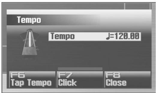
text_image
Tempo Tempo J=120.00 F6 Tap Tempo F7 Click F8 CloseTo close a window, press [EXIT]. Some windows will close automatically when you perform an operation.
Moving the Cursor
A single screen or window can contain multiple items (parameters) to set or select. If you want to modify the setting of a parameter, move the cursor to the value of that parameter. To select an item, move the cursor to the desired item. The value or item selected by the cursor will be highlighted.
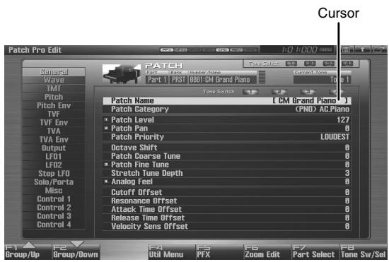
text_image
Cursor Patch Pro Edit PATCH Tang Select Current Tone Part 1 | PRST GB81GM Grand Piano Tang Switch Patch Name [ CM Brand Piano ] Patch Category (PND) AC.Piano Patch Level 127 Patch Pan 0 Patch Priority LOUDEST Octave Shift 0 Patch Coarse Tune 0 Patch Fine Tune 0 Stretch Tune Depth 3 Analog Feel 0 Cutoff Offset 0 Resonance Offset 0 Attack Time Offset 0 Release Time Offset 0 Velocity Sens Offset 0Use ▲ / ▼ / ◀ / ▶ (cursor buttons) to move the cursor.
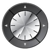
▲ : Moves the cursor upward.
▼ : Moves the cursor downward.
◀ : Moves the cursor to the left.
▶ : Moves the cursor to the right.
TIP
If you hold down a cursor button and then press the opposite cursor button, the cursor will move more rapidly in the direction of the button you pressed first.
TIP
In some cases, pressing [ENTER] while the cursor is displayed will show a list of the parameters you can select. This is a convenient way to see the choices you have. When a list is displayed, you can also use the pads to input your choice (p. 41).
Using the mouse for selection
If you're using a USB mouse, you can move the cursor by clicking the mouse on a parameter value.
Editing a Value
To edit a value, you can use either the VALUE dial or [INC] [DEC].

In each of the Fantom-G's screens, move the highlighted cursor to the value you want to edit, and then edit the value.
VALUE dial
Turn the VALUE dial toward the right to increase the value, or toward the left to decrease it. The value will change in larger steps if you hold down [SHIFT] while turning the VALUE dial.
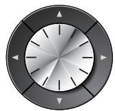
When the cursor is located at a parameter value, pressing [ENTER] (or right-clicking the USB mouse) will open a window where you can specify the value. You can easily select a value by pressing ▲ or ▼ to select the desired value and then pressing [ENTER].
[INC], [DEC]
Press [INC] to increase a value, or [DEC] to decrease it. To make the value continue increasing (or decreasing), hold down the button. To make the value increase rapidly, hold down [INC] and then press [DEC]. Conversely, to make the value decrease rapidly, hold down [DEC] and then press [INC].
The value will change in larger steps if you hold down [SHIFT] while you press [INC] or [DEC].
![ROLAND FANTOM G8 - [INC], [DEC] - 1](/content/2025/01/130804/images/88ab0b9370d8d0c05069ad915e3a97b3de32c81b9f1faa79f0e5726fb7c0c4f9.jpg)
text_image
EXIT ENTER SHIFT DEC INCUsing the mouse for input
Drag up/down or left/right on the value or knob. Dragging up or to the right will increase the value, and dragging down or to the left will decrease the value.
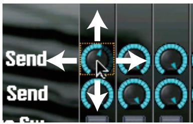
text_image
Send Send to RunUsing the pad for numeric input
If you press the [NUMERIC] pad button, the pads will operate as numeric keys.
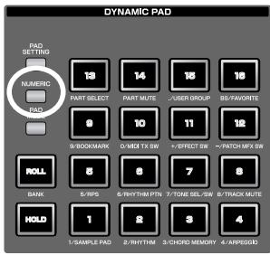
text_image
DYNAMIC PAD PAD SETTING NUMERIC PAD PART SELECT PART MUTE USER GROUP BS-FAVORTE 9/BOOKMARK 0-MIDI TX SW +/-EFFECT SW ~/PATCH MPX SW 8 6 7 8 5/RPS 6/RHYTHM PTN 7/TONE SEL/SW 8/TRACK MUTE 1/SAMPLE PAD 2/RHYTHM 3/CHORD MEMORY 4/APPEGOODEach pad will enter the following values
| Pad | Value entered |
| 1–9 | 1–9 |
| 10 | 0 |
| 11 | + |
| 12 | - |
| 15 | , (comma) |
| 16 | BS (backspace) |
| ROLL | Cancel |
| HOLD | Enter |
When you've entered the value, press [ENTER] to finalize your input. If you decide to cancel, press [EXIT].
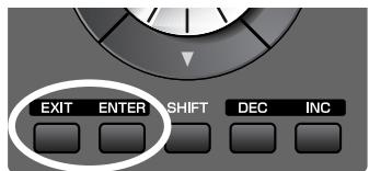
text_image
EXIT ENTER SHIFT DEC INCUsing the knobs for input
If the display shows small numerals (1, 2, 3, 4), you can use knobs 1–4 to edit the corresponding parameters.
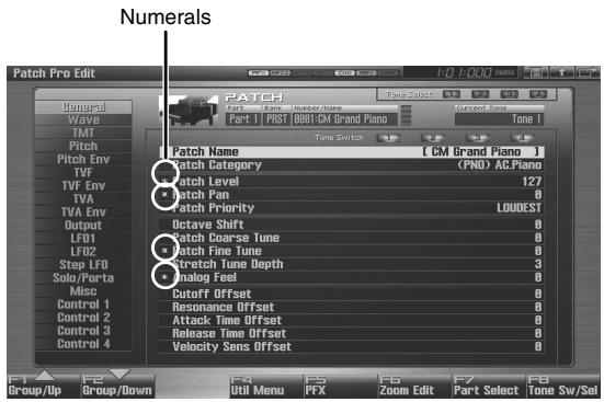
text_image
Numerals Patch Pro Edit PATCH Tone Select 10:10:00 PATCH Part | FIRST 08B11CM Grand Piano Tone 1 Tone Switch Patch Name [ CM Grand Piano ] Patch Category (PND) AC.Piano Patch Level 127 Patch Pan 0 Patch Priority LOUDEST Octave Shift 0 Patch Coarse Tune 0 Patch Fine Tune 0 Stretch Tune Depth 3 Dialog Feel 0 Dutoff Offset 0 Resonance Offset 0 Attack Time Offset 0 Release Time Offset 0 Velocity Sens Offset 0
text_image
1 2 3 4 MAGIC CTRLAssigning a Name
On the Fantom-G you can assign a name to each patch, rhythm set, live set, studio set, song, phrase, or sample when you save it. Regardless of the type of object you're naming, the procedure is the same.
- Use [CURSOR] to move the cursor to the position at which you want to enter a character.
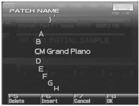
text_image
PATCH NAME PAD Group Pad Part Sample Sample PAD Mode Internal Part 7 Sample SAMPLE PAD A B CM Grand Piano D E F G H MODULATE RFTERTOUCH BERTIH FOOT TYPE 1, 2, 3, 4, 5 MODULATION DOCUMENTS NORMAL OFF F5 F6 F7 F8 Delete Insert Cancel OK-
Turn the VALUE dial or use [INC] [DEC] to specify the character that you want to enter.
-
[F5 (Delete)]: Deletes the character at the cursor, and moves the subsequent characters one place forward.
• [F6 (Insert)]: Inserts a space at the cursor location.
• [F7 (Cancel)]: Cancels the name entry procedure.
• [F8 (OK)]: Confirms the name.
• [ ◀ ] [ ▶ ]: Move the cursor.
• [ ▲ ] [ ▼ ]: Switch between uppercase and lowercase letters.
You can use the following characters,
$$ \begin{array}{l} \text {space, A - Z, a - z, 0 - 9 , !'' # \% \& ' () * + , - . / : ; < = > ? @ [ \backslash ] ^ {\wedge}} \ {\mid } \end{array} $$
NOTE
When assigning a name to a song file, you can't use spaces, lowercase letters, or certain symbols (\ / : ,; * ? " < > |).
Using a mouse to input characters
If you're using a USB mouse, you can enter characters using a virtual keyboard.
-
Click the mouse on the keyboard icon shown in the name entry screen.
The virtual keyboard will appear. -
Click the mouse on the keyboard to enter characters.
-
Press [F8 (OK)] or click it with the mouse to finalize the input.
MEMO
If you use the virtual keyboard for entry, it will be shown again the next time you enter a name.
Basic Pad Operations
For details on using the pads, refer to "Using the Pads" (p. 188).
Switching the Pad Mode
The pads have sixteen modes. Press [PAD MODE] to switch the pad mode.
1. Press [PAD MODE].
[PAD MODE] will blink, and the currently selected pad mode (pad [1]–[16]) will blink.
![ROLAND FANTOM G8 - Press [PAD MODE]. - 1](/content/2025/01/130804/images/46d0a9e1c1ba431bf13edbde059e567439044b65c6276717bfc51f7936bccf80.jpg)
If you decide not to switch the pad mode, press [PAD
MODE] once again. [PAD
MODE] will go out and you
will return to the previous state.
![ROLAND FANTOM G8 - Press [PAD MODE]. - 2](/content/2025/01/130804/images/4aee1aa9fb49fc7c20c257fd39110bd76c0f9888a24af34ca681be9ace8bb730.jpg)
text_image
DYNAMIC PAD PAD SETTING NUMERIC PAD MODE 19 14 16 18 PART SELECT PART MUTE /USER GROUP BS/FAVORITE 9 10 11 12 B/BOOKMARK O/METX SW +/EFFECT SW -/PATCH M/FX SW ROLL 5 6 7 8 BANK 5/IPS 6/RHYTHM PTR 7/TONE SEL/GW 8/TRACK MUTE HOLD 1 2 3 4 1/SAMPLE PAD 2/RHYTHM 3/CYORD MEMORY 4/ARPEGGO2. Press a pad [1]–[16].
The pad mode will be switched. The following table shows what the pads do in each mode, and a page reference where you can learn more.
| Pad number | Pad mode | Explanation | Page reference |
| 1 | SAMPLE PAD | Play a sample set | p. 191 |
| 2 | RHYTHM | Play a rhythm set | p. 192 |
| 3 | CHORD MEMORY | Switch the chord form of the Chord Memory function (p. 81) | p. 193 |
| 4 | ARPEGGIO | Switch the style of the Arpeggio function (p. 78) | p. 193 |
| 5 | RPS | Play phrases | p. 194 |
| 6 | RHYTHM PTN | Play rhythm patterns | p. 196 |
| 7 | TONE SEL/SW | Act as tone select and on/off switches | p. 197 |
| 8 | TRACK MUTE | Switch the mute status of the sequencer tracks | p. 197 |
| 9 | BOOKMARK | Call up frequently used screens you’ve registered for each pad | p. 198 |
| 10 | MIDI TX SW | Act as on/off switches for external MIDI transmit channels (1-16) | p. 198 |
| 11 | EFFECT SW | Act as effect switches (except for patch multi-effect) | p. 199 |
| 12 | PATCH MFX SW | Act as multi-effect switches for each part | p. 199 |
| 13 | PART SELECT | Select parts (1-16) and banks (INT/EXP1/EXP2/EXT) | p. 200 |
| 14 | PART MUTE | Switch the mute status of parts (1-16) and banks (INT/EXP1/EXP2/EXT) | p. 200 |
| 15 | USER GROUP | Store/load user group patches, live sets, or studio sets | p. 201 |
| 16 | FAVORITE | Store/load favorite settings | p. 202 |
Viewing the Pad Settings
Press [PAD SETTING], and the setting/information screen for the currently selected pad mode will appear.

To go back to where you were, press [PAD SETTING] once again so its light goes out.
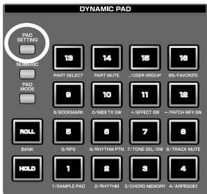
text_image
DYNAMIC PAD PAD SETTING NURRIC 13 14 15 16 PART SELECT PART MUTE USER GROUP B5/FAVORITE PAD MODE 9 10 11 12 9/BOOKMARK 0/MIDI TX SW +/-EFFECT SW ~/-PATCH MFX SW ROLL 8 6 7 8 BANK 5/NPS 6/RHYTHM PTN 7/TONE SEL/SW 8/TRACK MUTE HOLD 1 2 3 4 1/SAMPLE PAD 2/RHYTHM 3/CHORD MEMORY 4/ARPEGGOUsing the Pads as Numeric Keys
If you press PAD [NUMERIC], the pads will operate as numeric keys. → “Using the pad for numeric input” (p. 41)
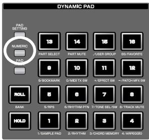
text_image
DYNAMIC PAD PAD SETTING 1 Numeric PART SELECT PART MUTE USER GROUP BS/FAVORITE PAD 9/BOOKMARK 0/MIDI TX SW /-EFFECT SW /-PATCH MFX SW ROLL 5/RPS 6/RHYTHM PTN 7/TONE SEL/SW 8/TRACK MUTE BANK 5/RPS 6/RHYTHM PTN 7/TONE SEL/SW 8/TRACK MUTE HOLD 1/SAMPLE PAD 2/RHYTHM 3/CHORD MEMORY 4/ARPEGGGShortcut Menu
By pressing the [DISPLAY] button, you can jump directly to the most important screens.
1. Press [DISPLAY].
![ROLAND FANTOM G8 - Press [DISPLAY]. - 1](/content/2025/01/130804/images/fd27f9976b1cb3301982fdf9461ec32b680127dcc66887c221f24cabb2a8855c.jpg)
text_image
F5 F6 F7 F8 5 6 7 8 DISPLAYThe Shortcut menu will appear.
MEMO
You can also open the Shortcut menu by clicking your USB mouse on the shortcut icon.
2. Press ▲ or ▼ to select the screen to which you want to jump, then press [F8 (Select)].
If you decide to cancel, press [F7 (Cancel)].
List of shortcut menu
| Menu | Page |
| Studio Play/Live Play/Single Play | p. 66, p. 58. p. 46 |
| Patch Zoom Edit | p. 84 |
| Patch Pro Edit | p. 86 |
| Song Play/Song Edit | p. 205, p. 232 |
| Sample Edit | p. 266 |
| Effects Routing | p. 151 |
| Sampling | p. 260 |
| Input Setting | p. 258 |
| Digital/USB Input Level | p. 301 |
| Master Level | p. 297 |
| Pad Setting | p. 190 |
02: Sound Generator, Section 1 (Playing Sounds)
This chapter explains the three modes in which the Fantom-G's sound generator can operate.
- Single Mode ...... p. 46
• Live Mode......p. 58 - Studio Mode ...... p. 66
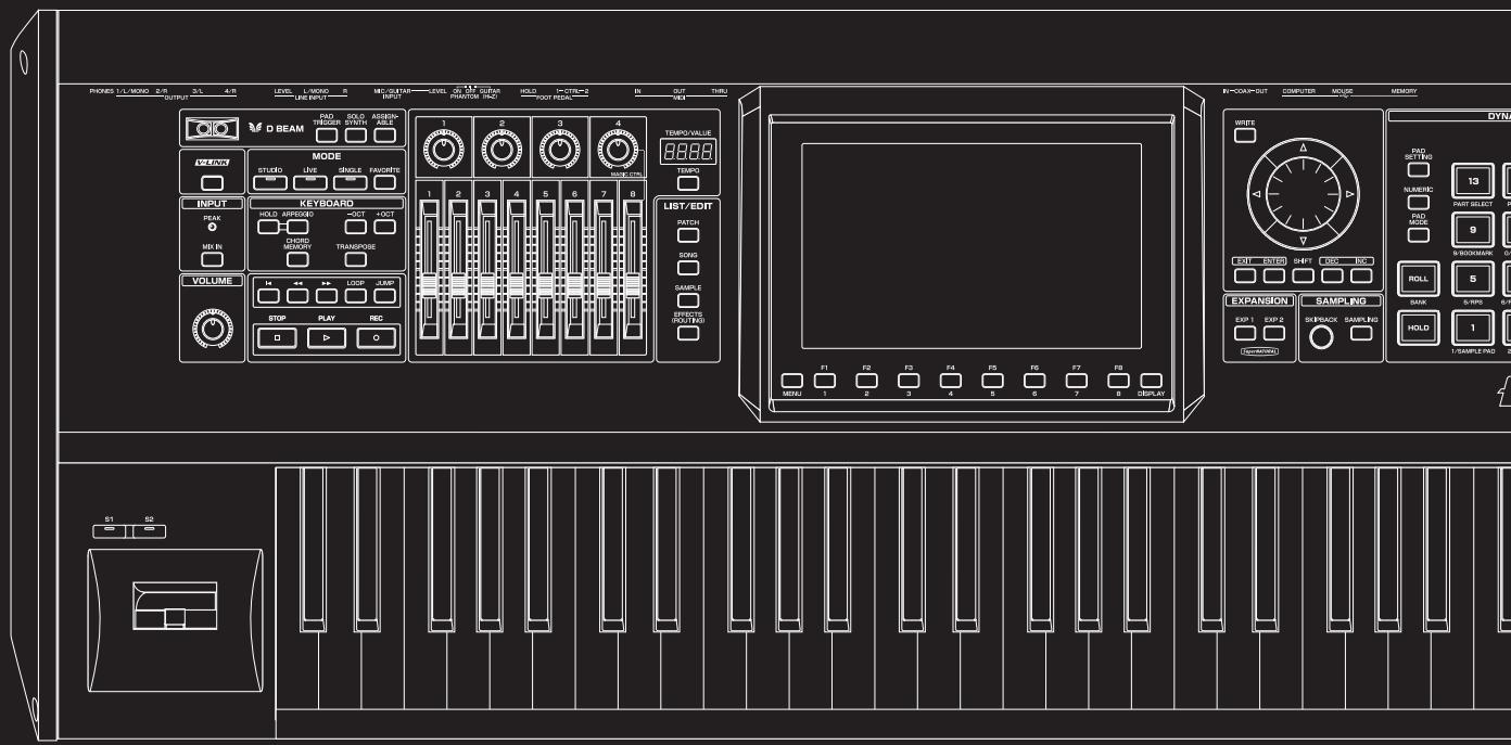
text_image
PROKES L/L MISO 2/R 3/L 4/R LEVEL L-MISO 5 MECUTAIN LEVEL 6 M.1.2 CIRCUA HOLD I-CTR=2 IN OUT TURU OUTPUT LINE INPUT INPUT PRANTOR PAC FOUR PIEDAL IN V8 D BEAM SOLDER STUDIO ASSUMPTION MODE TEMPO VALUE MODE STUDIO LIVE SINGLE FAVORATE INPUT PEAK HOLD APPROXED 3OCT 4OCT CHORD MD IN CHORD WINDOW TRANSPONSE VOLUME STOP PLAY REC LIST/EDIT PATCH DOYS SAMPLE CAPSIC ROLL/TWO EXPANSION SAMPLING EXP 1 EXP 2 SREBACK SAMPLING HOLD 1 SAMPLE RAD 2 F1 F2 F3 F4 F5 F6 F7 F8 MIN: 1 2 3 4 5 6 7 8 DISPLAYIn Single mode, the keyboard and the pads are each used to play a single sound (patch/rhythm set/sample set).
About the Single Play Screen
Displaying Single Play Screen
To access the Single Play screen, use the following procedure.
1. Press [SINGLE].
![ROLAND FANTOM G8 - Press [SINGLE]. - 1](/content/2025/01/130804/images/9d7a33ae9f0971a1331cd23b4ca4b36d0232aed451d068ee08de0d5456a75601.jpg)
text_image
MODE STUDIO LIVE SINGLE FAVORITEYou will enter Single mode, and the Single Play screen appears.
![ROLAND FANTOM G8 - Press [SINGLE]. - 2](/content/2025/01/130804/images/3c057886e965e15cb045f7bf33068c94f79267a625daf8328016bc79dced96d0.jpg)
text_image
Single Play MyBlock Control Part 1 Patch FST Piano (PAD) AC Piano OFF 0001:G-Grand Tone Switch Dynamic Pad Control Part 7 Sample SAMPLE PAD USER 001:INITIAL SAMPLE 1 2 3 4 5 6 7 8 Patch Number Name: 0001(G-SW) F4 Patch List F2 F3 Part View F4 F5 Control F6 F7 F8 User Group F9 Patch Edit F10 Tone Sw/SellF-key operations in the Single Play screen
| F-key | Explanation | Page |
| F1Patch List | Select a sound (patch). | p. 49 |
| F3Part View | Make detailed settings for each part (keyboard, sample pad, rhythm part). | p. 51 |
| F4Control | Select the parameters that will be controlled by the realtime controllers and D Beam controller. | p. 51 |
| F5PFX | Access the PFX (Patch Multi-effect) editing screen. | p. 157 |
| F6User Group | Access the user group list screen, where you can register frequently-used patches. | p. 201 |
| F7Patch Edit | Edit a patch. | p. 84 |
| F8Tone Sw/Sel | Select the tones that will be heard. | p. 50 |
Functions in the Single Play screen
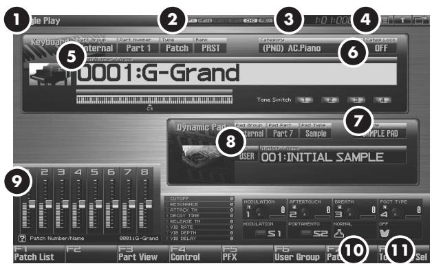
text_image
1 2 3 4 5 6 7 8 9 10 11 1 Patch Number/Name 0001:G-Grand Patch List F2 F3 Part View F4 F5 Control PFX User Group Pacl Tce Set Tone Switch Dynamic Pad 0001:G-Grand Punch Number/Name 0001:G-Grand Punch Number/Name 0001:G-Grand Punch Number/Name 0001:G-Grand Punch Number/Name 0001:G-Grand Punch Number/Name 0001:G-Grand Punch Number/Name 0001:G-Grand Punch Number/Name 0001:G-Grand| Number | Explanation | Page |
| 1 | Indicates the current sound generator mode. | p. 39 |
| 2 | Indicates the on/off status of each effect.PFX Patch multi-effectMFX1 Multi-effect 1MFX2 Multi-effect 2IFX Input effectCHO ChorusREV ReverbMAS Mastering effect | p. 150 |
| 3 | Indicates the current location of the song, and the status of the sequencer. | p. 205 |
| 4 | The Menu/Exit/Shortcut buttons for the USB mouse. | p. 26 |
| 5 | Indicates/selects the part group, part number, patch type, bank, number, and name of the selected patch, rhythm set, or sample set. | p. 47 |
| 6 | Indicates/selects the patch category, and specifies whether the category will be locked. | p. 48 |
| 7 | Indicates the pad mode. | p. 188 |
| 8 | Indicates/selects the part group, part, pad type, bank, number, and name of the rhythm set or sample set selected for the pads. | p. 52 |
| 9 | Indicates the functions assigned to the realtime controller sliders (1–8), knobs (1–4) and the S1/S2 switches. | p. 51 |
| 10 | Indicates the “Bend Mode” (p. 97) of the pitch bend lever. | p. 97 |
| 11 | Indicates the function assigned to the D Beam controller and the state of D Beam controller response. | p. 72 |
Selecting a Patch
The Fantom-G has four patch banks, including the User, Preset, User Sample and GM.
USER
This is the bank inside the Fantom-G which can be rewritten. Patches you create can be stored in this bank. You can store 512 patches.
PRST (Preset)
This is the bank inside the Fantom-G which cannot be rewritten. However you may modify the settings of the currently selected patch, and then store the modified patch in user bank.
GM (GM2)
This is an internal bank of patches compatible with General MIDI 2, a system of MIDI function specifications designed to transcend differences between makers and types of devices; these patches cannot be overwritten. However you may modify the settings of the currently selected patch, and then store the modified patch in user bank. The Fantom-G includes 256 preset patches.
USAM (User Sample)
This bank lets you play the Fantom-G's internal samples.
- Press [SINGLE] to access the Single Play screen.
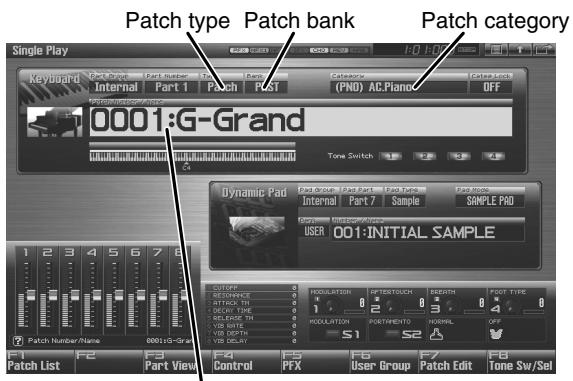
text_image
Patch type Patch bank Patch category 0001:G-Grand Dynamic Pad Internal Part 7 Sample SAMPLE PAD USER 001-INITIAL SAMPLE Patch Number/Name 0001:G-Grand Patch List F2 Part View F4 Control F5 PFX F6 User Group Patch Edit Tone Sw/SelPatch number / Patch name
- Press [CURSOR] to move the cursor to the patch bank. Turn the VALUE dial or use [INC] [DEC] to choose the patch bank.
USER: User
PRST: Preset
GM: GM (GM2)
USAM: User Sample
* Make sure that the patch type is set to "Patch." If this is set to "Rhythm" or "Sample," use [CURSOR] to move the cursor to the patch type, and turn the VALUE dial or press [DEC] to select "Patch."
-
Press [CURSOR] to move the cursor to the patch number.
-
Turn the VALUE dial, or press [INC] [DEC] to select a patch number.
MEMO
You can also use the pads as numeric keys to enter numbers (patch numbers). → “Using the pad for numeric input” (p. 41)
- Play the keyboard to hear the sound.
MEMO
You can also use the following methods to select a patch.
"Selecting Patches by Category (Patch Finder)" (p. 48)
"Selecting Patches from the List" (p. 49)
Selecting Patches by Category (Patch Finder)
The Fantom-G provides a “Patch Search function” (Patch Finder) which allows you to specify a type (category) of patch so that you can quickly find the desired patch. There are a total of 38 categories.
1. Press [SINGLE] to access the Single Play screen.
![ROLAND FANTOM G8 - Press [SINGLE] to access the Single Play screen. - 1](/content/2025/01/130804/images/dd29fa2f5ad80bb8e10e7ee86ae9a32e6c200567ddca95968dfdca7d3a8e082b.jpg)
text_image
MODE STUDIO LIVE SINGLE FAVORITE![ROLAND FANTOM G8 - Press [SINGLE] to access the Single Play screen. - 2](/content/2025/01/130804/images/3a3fc8cda6d9e769a239a6fca1e77affecd7e1b4f107d4bf9cd7d52ea8001eec.jpg)
text_image
Patch type Patch bank Patch category 10001:G-Grand Tone Switch Dynamic Pad Inner Part 7 Sample USER 001:INITIAL SAMPLE Patch Number Name 0001:G-Grand Patch List F2 F3 Part View F4 Control P5 F6 User Group F7 Patch Edit F8 Tone Sw/SelPatch number / Patch name
* Make sure that the patch type is set to "Patch."
If this is set to "Rhythm" or "Sample," use [CURSOR] to move the cursor to the patch type, and turn the VALUE dial or press [DEC] to select "Patch."
2. Use [CURSOR] to move the cursor to the "Patch Category," and turn the VALUE dial, or press [INC] [DEC] to select the desired category.
3. Press ▶ to move the cursor to "Categ Lock," and turn the VALUE dial or press [INC] to turn "ON".
4. Use [CURSOR] to move the cursor to the patch bank or patch number, and turn the VALUE dial or use [INC] [DEC] to select the patch.
When the cursor is located at the Patch bank, you can select the bank. When the cursor is located at the Patch number, you can specify the number.
MEMO
You are free to change the category of a patch by editing the Patch Pro Edit screen (p. 86) parameter “Patch Category” (p. 89).
The following categories can be selected.
| Category | Contents | |
| --- | No Assign | No assign |
| PNO | AC.Piano | Acoustic Piano |
| EP | EL.Piano | Electric Piano |
| KEY | Keyboards | Other Keyboards (Clav, Harpsichord etc.) |
| BEL | Bell | Bell, Bell Pad |
| MLT | Mallet | Mallet |
| ORG | Organ | Electric and Church Organ |
| ACD | Accordion | Accordion |
| HRM | Harmonica | Harmonica, Blues Harp |
| AGT | AC.Guitar | Acoustic Guitar |
| EGT | EL.Guitar | Electric Guitar |
| DGT | DIST.Guitar | Distortion Guitar |
| BS | Bass | Acoustic & Electric Bass |
| SBS | Synth Bass | Synth Bass |
| STR | Strings | Strings |
| ORC | Orchestra | Orchestra Ensemble |
| HIT | Hit&Stab | Orchestra Hit, Hit |
| WND | Wind | Winds (Oboe, Clarinet etc.) |
| FLT | Flute | Flute, Piccolo |
| BRS | AC.Brass | Acoustic Brass |
| SBR | Synth Brass | Synth Brass |
| SAX | Sax | Sax |
| HLD | Hard Lead | Hard Synth Lead |
| SLD | Soft Lead | Soft Synth Lead |
| TEK | Techno Synth | Techno Synth |
| PLS | Pulsating | Pulsating Synth |
| FX | Synth FX | Synth FX (Noise etc.) |
| SYN | Other Synth | Poly Synth |
| BPD | Bright Pad | Bright Pad Synth |
| SPD | Soft Pad | Soft Pad Synth |
| VOX | Vox | Vox, Choir |
| PLK | Plucked | Plucked (Harp etc.) |
| ETH | Ethnic | Other Ethnic |
| FRT | Fretted | Fretted Inst (Mandolin etc.) |
| PRC | Percussion | Percussion |
| SFX | Sound FX | Sound FX |
| BTS | Beat&Groove | Beat and Groove |
| DRM | Drums | Drum Set |
| CMB | Combination | Other patches which use Split and Layer |
MEMO
You can't select categories for rhythm sets or sample sets.
Selecting Patches from the List
You can display a list of patches and select a patch from that list.
- Press [SINGLE] to access the Single Play screen.
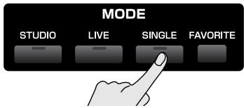
text_image
MODE STUDIO LIVE SINGLE FAVORITE- Press [F1 (Patch List)].
The Patch List screen will appear.
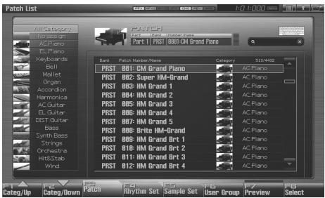
text_image
Patch List Part 1 PAST B01-GM Grand Piano Best Patch Name/Name Category: 9134432 PRST BB1: CM Grand Piano PRST BB2: Super HM-Grand PRST BB3: HM Grand 1 PRST BB4: HM Grand 2 PRST BB5: HM Grand 3 PRST BB6: HM Grand 4 PRST BB7: HM Grand 5 PRST BB8: Drite HM-Grand PRST BB9: HM Grand Brt 1 PRST B10: HM Grand Brt 2 PRST B11: HM Grand Brt 3 PRST B12: HM Grand Brt 4 AC Piano AC Piano AC Piano AC Piano AC Piano AC Piano AC Piano AC Piano AC Piano AC Piano AC Piano AC Piano AC Piano AC Piano AC Piano AC Piano AC Piano AC Piano AC Piano AC Piano AC Piano AC Piano AC Piano AC Piano AC Piano AC Piano AC Piano AC Piano AC Piano AC Piano AC Piano AC Piano AC Piano AC PianoYou can use [F3 (Patch)], [F4 (Rhythm Set)], and [F5 (Sample Set)] to switch between patch types (patches, rhythm sets, samples sets).
- Use [F1] [F2] or ◀ / ▶ to select a category.
MEMO
You can also use the front panel [Knob 4] to select a category, and use [Slider 8] to scroll the list.
→ “Magic Control” (p. 294)
MEMO
You can't select categories for rhythm sets or sample sets.
- Turn the VALUE dial or use [DEC] [INC] or ▲ / ▼ to select a patch.
MEMO
You can press [F7 (Preview)] to audition the patch using an appropriate phrase that is preset for each category (Phrase Preview).
MEMO
By pressing [F6 (User Group)] you can register a frequently used sound in the user group. For details, refer to “Registering a sound in the User Group screen” (p. 201).
MEMO
If you're using a USB mouse, you can click the keyboard symbol
in the screen, and search using the virtual keyboard that appears in the screen.
- Press [F8 (Select)] to confirm your patch selection.
Auditioning Patches (Phrase Preview)
The Fantom-G allows you to preview patches by hearing a phrase appropriate for each type of patch.
- Press [SINGLE] to access the Single Play screen.
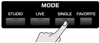
text_image
MODE STUDIO LIVE SINGLE FAVORITE- Press [F1 (Patch List)] to access the Patch List screen.
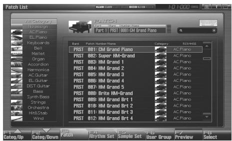
text_image
Patch List Cate/Up Cate/Down Catch Rhythm Set Sample Set User Group Preview Select- Press and hold [F7 (Preview)].
The patch selected in the Patch List screen will be sounded.
- Release your finger from [F7 (Preview)], and the phrase will stop playing.
cf.
If you wish to change how the phrase is played by Phrase Preview, you can edit the Preview Mode parameter (p. 300).
Selecting the Tones That Will Sound (Tone On/Off)
Since a patch is a combination of up to four tones, you can switch unwanted (tones out of the four) off and get just the sound of a specific tone.
- Press [SINGLE] to access the Single Play screen.
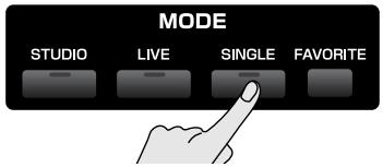
text_image
MODE STUDIO LIVE SINGLE FAVORITE- Press [F8 (Tone Sw/Sel)].
The Tone Switch/Select window appears.

text_image
Tone Switch/Select (Full) (Push [EXIT] to close) F1 F2 F3 F4 F5 F6 F7 F8 Sw 1 Sw 2 Sw 3 Sw 4 Select 1 Select 2 Select 3 Select 4-
Press [F1 (Tone Sw)]-[F4 (Tone Sw)] to turn each tone on/off. The setting will switch on/off each time you press the button.
-
Press [EXIT] to close the window.
TIP
If you want just one or two tones to sound in a patch, turn the others off and store that setting on a patch. This cuts nonessential use of the Fantom-G's simultaneous voices.
TIP
You can also use the pads to select tones and switch them on/off (p. 197).
Playing Single Notes (Monophonic)
When using a patch for a naturally monophonic instrument such as sax or flute, it is effective to play in mono.
- Press [SINGLE] to access the Single Play screen.
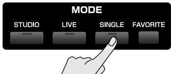
text_image
MODE STUDIO LIVE SINGLE FAVORITE- Press [PATCH] twice to access the Patch Pro Edit screen.
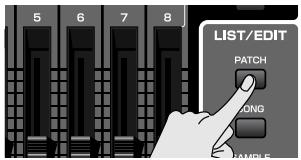
text_image
5 6 7 8 LIST/EDIT PATCH LONG SAMPLE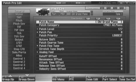
text_image
Patch Pro Edit Bunand Wave IMI Pitch Patch Env TVF TVF Env TVA TVA Env Output LFO1 LFO2 Step LFO Solo/Parts Misc Control 1 Control 2 Control 3 Control 4 F1 F2 F3 F4 F5 F6 F7 F8 Group/Up Group/Down Patch Name [CM Grand Piano] Patch Category (PNO) ACPiano Patch Level 127 Patch Ion 0 Patch Priority LOUDEST Octave Shift 0 Patch Coarse Tune 0 Patch Fine Tune 0 Stretch Tone Depth 3 Analog Feel 0 Cutoff Offset 0 Resonance Offset 0 Attack Time Offset 0 Release Time Offset 0 Velocity Sens Offset 0- Press [F1 (Up)] or [F2 (Down)] to select the "Solo/Porta" tab.
A screen like the one shown below appears.
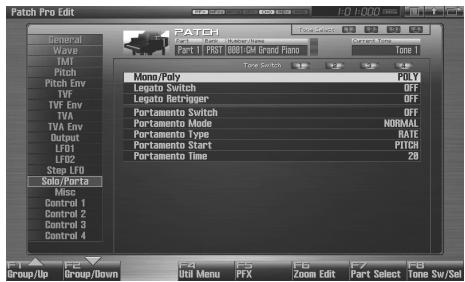
text_image
Patch Pro Edit General Wave IMI Pitch Pitch Env TVF TVF Env TVA TVA Env Output LFD1 LFD2 Step LFD Solo/Porta Misc Control 1 Control 2 Control 3 Control 4 PATCH Current Tools PART 1 PRINT B8B1-DM Grand Piano Type Switch Mono/Poly Poly Legato Switch OFF Legato Retrigger OFF Portamento Switch OFF Portamento Mode NORMAL Portamento Type RATE Portamento Start PITCH Portamento Time 20 F1 F2 F3 F4 F5 F6 F7 F8 Group/Up Group/Down Util Menu PFX Zoom Edit Part Select Tone Sw/Sel-
Press ▲ or ▼ to move the cursor to "Mono/Poly."
-
Turn the VALUE dial or press [DEC] to select "MONO."
Now you can play in mono mode.
TIP
If you assign "MONO/POLY" as a function to be controlled by the assignable switch ([S1] [S2]), you can easily switch between mono/poly by pressing a button (p. 77).
Part Settings (Part View)
Single mode has the following three parts.
| Part | Explanation | |
| 1 | Keyboard | The part that is heard when you play the keyboard |
| 7 | Sample Pad | The part that is heard when you set the pads to “1 SAMPLE PAD (Using the Pads to Play Samples)” (p. 191) mode |
| 8 | Rhythm Pad | The part that is heard when you set the pads to “2 RHYTHM (Using the Pads to Play a Rhythm Set)” (p. 192) mode |
In the Part View screen you can view and edit the volume and pan settings of these three parts.
- Press [SINGLE] to access the Single Play screen.
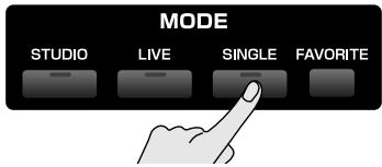
text_image
MODE STUDIO LIVE SINGLE FAVORITE- Press [F3 (Part View)].
The Part View screen will appear.

text_image
Part View (Single) Internal EXP 1 EXP 2 External Level/Pan 7 SAMPLES USER GB1/CM Grand Piano 100 1 0 ✓ Ch1 Keyboard 8 MULTINUM PRST GB1/6 Standard Kit 100 1 0 ✓ Ch9 Output/EFX Pitch Scale Tone Vibrate Offset Mono/Poly/Legato Voice Reserve MIDI Rx Filter Part Level (COM 7) (0) F1 F2 F3 F4 F5 F6 Group/Up Group/Down Interval EXP 1 EXP 2 External Sys Write F6 F1 F2 F3 F4 F5 F6 External- Press [F1 (Up)] or [F2 (Down)] to select the parameter group.
- Use [CURSOR] to move the cursor to the parameter.
- Either turn the VALUE dial or use [INC] [DEC] to set the value.
- If you want to keep the settings, press [F7 (Sys Write)].
NOTE
When Single mode is selected, part settings cannot be saved for each individual patch. Part settings are saved as system settings.
- When you have finished making settings, press [EXIT] to return to the Single Play screen.
cf.
See “Level/Pan (When the Part Group is Internal/EXP1/EXP2)” (p. 134)–“MIDI Rx Filter” (p. 141) for each parameter’s functions.
Selecting the Parameter Controlled by the Realtime Controllers or D Beam Controller (Control Setting)
The Fantom-G lets you assign the parameters that will be affected when you operate the 1–4 knobs, 1–8 sliders, S1/S2 switches, D Beam, pitch bend, or modulation lever. This lets you modify the sound in a variety of ways by operating the controllers.
- Press [SINGLE] to access the Single Play screen.
text_image
MODE STUDIO LIVE SINGLE FAVORITE- Press [F4 (Control)].
The Control Setting screen will appear. - Press [F1 (Up)] or [F2 (Down)] to select the parameter group.
- Use [CURSOR] to move the cursor to the parameter.
- Either turn the VALUE dial or use [INC] [DEC] to set the value.
- If you want to keep the settings, press [F7 (Sys Write)].
NOTE
When Single mode is selected, controller settings cannot be saved for each individual patch. Controller settings are saved as system settings.
- When you have finished making settings, press [EXIT] to return to the Single Play screen.
cf.
See “Keyboard Mode” (p. 143)–“Ctrl Switch” (p. 147) for each parameter’s functions.
Controller Reset
In Single mode, you can hold down [SHIFT] and press [SINGLE] to reset the controllers.
In addition to controllers such as bender, modulation, and pedals, the values of the following part parameters will also be initialized.
Cutoff Offset, Resonance Offset, Attack Time Offset, Release Time Offset, Decay Time Offset, Vibrato Rate, Vibrato Depth, Vibrato Delay
Playing Percussion Instruments (Rhythm Set)
In Single mode, you can play percussion instruments from the keyboard by selecting a rhythm set.

You can also use the pads to play a rhythm set. p. 192
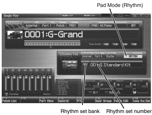
text_image
Single Play Keyboard Ure-Scropt Part Number Tune Dance Internal Part 1 Patch PRST Categories (PNO) AC.Piano OFF Pad Mode (Rhythm) 10001:G-Grand Tone Switch Dynamic Pad Pain Grounds & Rhythm Internal Part 8 Rhythm Rhythm 1 2 3 4 5 6 7 8 1 2 3 4 5 6 7 8 Dynamic Pad Pain Grounds & Rhythm Rhythm 1 2 3 4 5 6 7 8 Dynamic Pad Pain Grounds & Rhythm Rhythm 1 2 3 4 5 6 7 8 Dynamic Pad Pain Grounds & Rhythm Rhythm 1 2 3 4 5 6 7 8 Dynamic Pad Pain Grounds & Rhythm Rhythm 1 2 3 4 6 7 8 Dynamic Pad Pain Grounds & Rhythm Rhythm 1 2 3 4 5 6 7 8 Dynamic Pad Pain Grounds & Rhythm Rhythm 1 2 3 4 5 6 7 8 Dynamic Pad Pain Grounds & Rhythm Rhythm 1 2 3 4 5 6 7 8 Dynamic Pad (RGB Standard Kit) 1 2 3 4 5 6 7 8 Dynamic Pad (RGB Standard Kit) 1 2 3 4 5 6 7 8 Dynamic Pad (RGB Standard Kit) 1 2 3 4 5 6 7 8 Dynamic Pad (RGB Standard Kit) 1 2 3 4 5 6 7 8 Dynamic Pad (RGB Standard Kit) 1 2 3 4.5/10000000000000000000000000000000000000000000000000000000000000000000000000000000000000000000000000000 F1 F2 F3 F4 F5 F6 F7 F8 F9 F10 F11 F12 F13 F14 F15 F16 F17 F18 F19 F20 F21 F22 F23 F24 F25 F26 F27 F28 F29 F30 F31 F32 F33 F34 F35 F36 F37 F38 F39 F40 F41 F42 F43 F44 F45 F46 F47 F48 F49 F50 F51 F52 F53 F54 F55 F56 F57 F58 F59 F60 F61 F62 F63 F64 F65 F66 F67 F68 F69 F70 F71 F72 F73 F74 F75 F76 F77 F78 F79 F80 F81 F82 F83 F84 F85 F86 F87 F88 F89 F90 F91 F92 F93 F94 F95 F96 F97 F98 F99 GND GND GND GND GND GND GND GND GND GND GND GND GND GND GND GND GND GND GND GND GND GND GND GND GND GND GND GND GND GND GND GND GND GND GND GND GND GND GND GND GND GND GND GND GND GND GND GND GND GND GUND GND GND GND GND GND GND GND GND GND GND GND GND GND GND GND GND GND GND GND GND GND GND GND GND GND GND GND GND GND GND GND GND GND GND GND GND GND GND GND GND GND GND GND GND GND GND GND GND GND GNC Rhythm set bank Rhythm set numberSelecting a Rhythm Set
The Fantom-G has three rhythm set banks, including the User bank, Preset bank and GM bank, with 64 rhythm sets in the User bank, 64 rhythm sets in Preset bank, and 9 rhythm sets in GM bank.
USER
This is the bank inside the Fantom-G which can be rewritten. The rhythm sets you create can be stored in this bank. You can store 64 rhythm sets.
PRST (Preset)
This is the bank inside the Fantom-G which cannot be rewritten. However, you can modify the settings of the currently selected rhythm set, and then save the modified settings in User bank. The Fantom-G contains 64 preset rhythm sets.
GM (GM2)
This is an internal bank of rhythm sets compatible with General MIDI 2, a system of MIDI function specifications designed to transcend differences between makers and types of devices; these rhythm sets cannot be overwritten. However, you can modify the settings of the currently selected rhythm set, and then save the modified settings in User bank. The Fantom-G includes nine preset rhythm sets.
- Press [SINGLE] to access the Single Play screen.
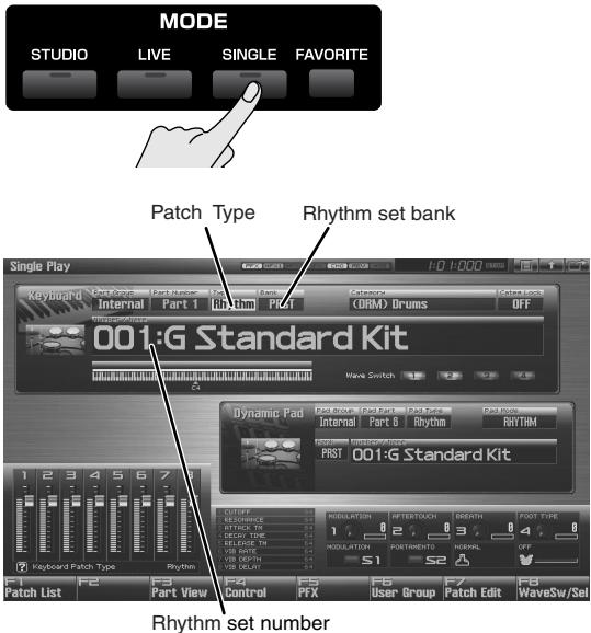
text_image
MODE STUDIO LIVE SINGLE FAVORITE Patch Type Rhythm set bank Single Play Keyboard Verance Part Number Chancers Saturns Internal Part I Rhythm PRT (ORM) Drums OFF Wave Switch 001:G Standard Kit Dynamic Pad Internal Part B Rhythm RHYTHM FIRST 001:G Standard Kit Keyboard Patch Type Rhythm Rhythm set number F1 Patch List F2 Part View F3 Control F4 F5 F6 F7 User Group F7 Patch Edit F8 WaveSw/Sel* Make sure that the Patch Type is set to "Rhythm." If this is set to "Patch" or "Sample," use [CURSOR] to move the cursor to the patch type, and turn the VALUE dial or press [INC] [DEC] to select "Rhythm."
- Press [CURSOR] to move the cursor to the rhythm set bank.
- Turn the VALUE dial or press [INC] [DEC] to select the rhythm set bank.
USER: User
PRST: Preset
GM: GM (GM2)
- Press [CURSOR] to move the cursor to the rhythm set number.
- Turn the VALUE dial or press [INC] [DEC] to select the rhythm set number.
- Play the keyboard to hear the sound.
Playing a Sample Set
In Single mode you can select a sample set and play the samples from the keyboard.

You can also use the pads to play a sample set. → p. 191
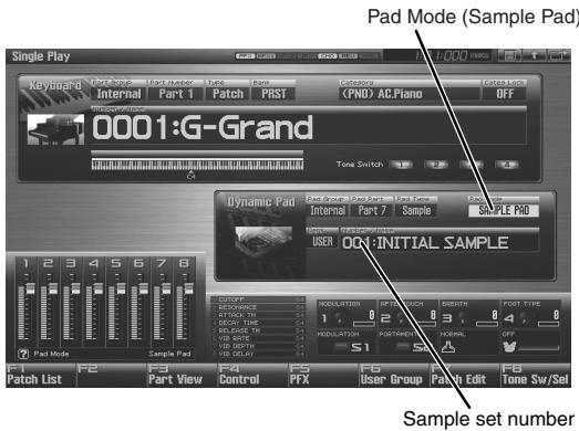
text_image
Pad Mode (Sample Pad) 10001:G-Grand Dynamic Pad Internal Part 7 Sample SAMPLE PAD USER ON:INITIAL SAMPLE Sample set number F1 F2 F3 F4 F5 F6 User Group Patch Edit F7 Tone Sw/Sell Patch List Part View Control PFX PFX Control OFFSelecting a Sample Set
- Press [SINGLE] to access the Single Play screen.
text_image
MODE STUDIO LIVE SINGLE FAVORITE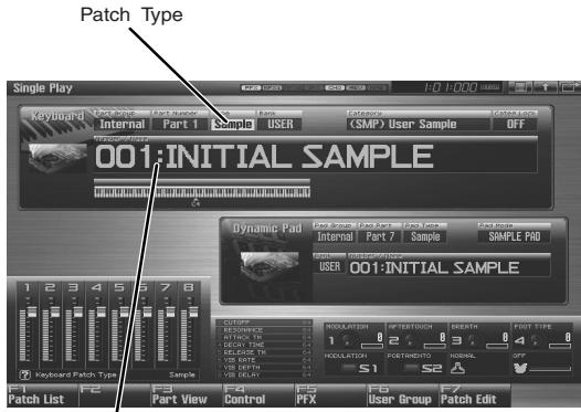
text_image
Patch Type 001:INITIAL SAMPLE Dynamic Pad 001:INITIAL SAMPLE Keyboard Patch Type F1 Patch List F2 Part View F3 Control F4 P5 PTX F6 User Group F7 Patch EditSample set number
* Make sure that the Patch Type is set to "Sample." If this is set to "Patch" or "Rhythm," use [CURSOR] to move the cursor to the patch type, and turn the VALUE dial or press [INC] [DEC] to select "Sample."
- Press [CURSOR] to move the cursor to the sample set number.
- Turn the VALUE dial or press [INC] [DEC] to select the sample set number.
- Play the keyboard to hear the sound.
* For a sample set, the sixteen sample tones are mapped to keys B3–D5.
Creating a List of Frequently Used Sounds (Favorite)
You can make a list of sounds that you frequently use in live performance, and recall these sounds instantly. You are free to register any type of sound — patches, rhythm sets, sample sets, live sets, studio sets, or songs — so you'll be able to instantly recall any sound you need for your performance.
You can register sixteen sounds (steps) in a bank, and you can create sixteen of these banks.
For example, up to sixteen sounds (steps) that you use in the first song of your live performance could be registered in bank 1, in the order in which they appear in the song.
Registering a Sound (Regist)
-
Access the screen for the patch (or rhythm set, sample set, live set, or studio set) that you want to register.
-
Press [FAVORITE] twice so it's blinking.
text_image
MODE STUDIO LIVE SINGLE FAVORITEThe Favorite Edit screen will appear.
MEMO
Each time you press [FAVORITE], you will alternate between the Favorite Play screen ([FAVORITE] lit) and the Favorite Edit screen ([FAVORITE] blinking).
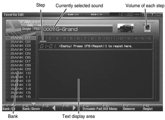
text_image
Step Currently selected sound Volume of each step Favorite Edit FAVORITE Single PRST 0001:G-Grand BANK 01 BANK 02 BANK 03 BANK 04 BANK 05 BANK 06 BANK 07 BANK 08 BANK 09 BANK 10 BANK 11 BANK 12 BANK 13 BANK 14 BANK 15 BANK 16 0 1-01 (Empty) Press [FB (Regist)] to regist here. F1 Bank/Up F2 Bank/Down F3 F4 F5 Dynamic Pad Util Menu F6 Remove F7 Regist Text display areaF-key operations in the Favorite Edit screen
| F-key | Explanation | Page | |
| F1 Bank ▲ | Selects the bank. | - | |
| F2 Bank ▼ | Selects the bank. | - | |
| F3 Step ◀ | Selects the step and recalls the sound. | p. 54 | |
| F4 Step ▶ | Selects the step and recalls the sound. | p. 54 | |
| F5 Dynamic Pad | Sets the pads in Favorite mode. | p. 54 | |
| F6 Util Menu | Font | Switches the display font | p. 57 |
| Set Song | Registers a song | p. 56 | |
| Import Text | Imports text | p. 56 | |
| Remove Text | Deletes text | p. 57 | |
| Remove Bank | Deletes a bank | p. 55 | |
| F7 Remove | Deletes the registration of a sound. | p. 55 | |
| F8 Regist | Registers a sound. | p. 54 | |
- Press [F1 Bank ▲] or [F2 Bank ▼] to select the bank in which you want to register the sound.
- Use the cursor buttons ◀ or ▶ to select the number (step) in which you want to register the sound.
You can register the sound in any of the sixteen steps. You'll want to register each sound in the order that's appropriate for the progression of your song or live performance.
- Press [F8 (Regist)] to register the sound.
For example if you registered the sound to number 02 of bank 1, the display will indicate "Regist to 1-02".
Recalling a Sound
Using the Favorite Play screen to recall sounds
- Press [FAVORITE] so it's lit.
MEMO
Each time you press [FAVORITE], you will alternate between the Favorite Play screen ([FAVORITE] lit) and the Favorite Edit screen ([FAVORITE] blinking).
- Press ▲ or ▼ to select the bank that you want to recall.
- Use [F1 (1)]-[F8 (8)] to select the step number that you want to recall.
If you want to select 9--16, hold down [SHIFT] and press [F1(9)]-[F8 (16)].
The selected sound will be recalled.
MEMO
As an alternative to step 3, you can also press ◀ or ▶ to select the he step number. In this case, the sound will not be switched until you press [ENTER].
Using the Favorite Edit screen to recall sounds
- Press [FAVORITE] twice so it's blinking.
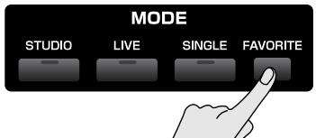
text_image
MODE STUDIO LIVE SINGLE FAVORITEThe Favorite Edit screen will appear.
- Press [F1 Bank ▲] or [F2 Bank ▼] to select the bank from which you want to recall sounds.
- Press [F3 Step ◀] or [F4 Step ▶] to select the step number (1–16) that you want to recall.
The selected sound will be recalled immediately.
TIP
As an alternative to step 3, you can also press ◀ or ▶ to select the he step number. In this case, the sound will not be switched until you press [ENTER].
Using the pads to recall sounds
-
In the Favorite Edit screen, press [F5 (Dynamic Pad)]. The pads will be set to Favorite mode.
-
Now you can press pads [1]–[16] to select the sound (step) that's registered for each pad.
- You can press ROLL to switch banks (1–6). → p. 189
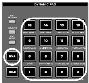
text_image
DYNAMIC PAD PAD SETTING NUMERC PAD MODE PART SELECT PART MUTE USER GROUP B5/FAVORTE 0 10 11 12 B/BOARDMARK 0/MDT TX SW +EFFECT SW ~PATCH M/FX SW 8 6 7 8 5/IPS 6/RHYTHM PTN 7/TONE SEL/SW 8/TRACK MUTE 1 2 3 4 HOLDNOTE
If you want to use the pads to successively switch between live sets (or studio sets), set the system parameter “Pad Assign Source” (p. 292) to “SYS.” If this is set to “TEMP,” the pad mode will change to the setting of that particular live set (or studio set) when you switch to a live set (or studio set).
Specifying the Volume for Each Step (Favorite Level)
Here's how to specify the volume (Favorite Level) for each step. Use this to adjust the volume of each sound in your live performance.
- In the Favorite Edit screen, press ◀ or ▶ to move the cursor to the step whose volume you want to adjust.
- Use knob 4 or [INC] [DEC] to specify the volume (Favorite Level).
Range: 0–127
Changing the Step in Which You Registered a Sound
Here's how to move a registered sound to a different step.
- In the Favorite Edit screen, press ◀ or ▶ to move the cursor to the step at which the sound you want to move is registered.
- While holding down [SHIFT], press ◀ or ▶ to move the sound.
Removing a Sound You Registered (Remove)
Here's how to remove a registered sound from the favorites list.
- In the Favorite Edit screen, press ◀ or ▶ to move the cursor to the step whose registration you want to remove.
- Press [F7 (Remove)].
For example if you remove the registration from step number 02 of bank 1, the display will indicate "Remove 1-02," and that step will be empty.
Removing All Sound Registrations from a Bank (Remove Bank)
Here's how to remove all sound registrations from a bank.
- In the Favorite Edit screen, press [F1 Bank ▲] or [F2 Bank ▼] to select the bank whose sound registrations you want to remove.
- Press [F6 (Util Menu)].
The Favorite Utility Menu window will appear.
- Press ▲ or ▼ to select "Remove Bank," and then press [F8 (Select)].
If you removed all registrations from bank 1, the display will indicate “Remove Bank 1,” and that bank will be empty.
Registering a Song (Set Song)
Here's how to register a song instead of a sound.
-
In the Favorite Edit screen, press [F1 Bank ▲] or [F2 Bank ▼] to select the bank in which you want to register a song.
-
Press ◀ or ▶ to select the number (step) in which you want to register a song.
-
Press [F6 (Util Menu)].
The Favorite Utility Menu window will appear.
- Press ▲ or ▼ to select "Set Song," and press [F8 (Select)].
The Song Select screen will appear.
-
Press ▲ or ▼ to select a song.
-
Press [F8 (Select)] to register the song.
For example if you register the song in number 02 of bank 1, the display will indicate "Regist to 1-02."
MEMO
Songs can be recalled in the same way as recalling sounds.
Importing a Text File (Import Text)
You can create a text file on your computer, and import it into the Fantom-G so that it can be displayed in the Favorite screen.
- Use the USB Storage function to place the text file in the "IMPORT" folder of the Fantom-G's internal memory or the USB memory.
cf.
"Exchanging Files with Your Computer (USB Storage)" (p. 285)
-
Access the Favorite Edit screen, and press [F1 Bank ▲] or [F2 Bank ▼] to select the bank in which you want to display the text.
-
Press [F6 (Util Menu)].
The Favorite Utility Menu window will appear.
-
Press ▲ or ▼ to select "Import Text," and then press [F8 (Select)].
-
Press [F1 (Internal)] or [F2 (USB Memory)] to select the import-source area (either internal memory or USB memory).
-
Press ▲ or ▼ to select the file that you want to import.
-
Press [F8 (Import Text)].
The file to be imported will appear.
* If you decide to cancel, press [F7 (Cancel)].
- Press [F8 (Execute)].
The file will be imported.
* If you decide to cancel, press [F7 (Cancel)].
MEMO
You can scroll the screen by pressing ▲ or ▼.
Removing a Text File (Remove Text)
Here's how to remove a text file that you imported.
-
Access the Favorite Edit screen, and press [F1 Bank ▲] or [F2 Bank ▼] to select the bank whose text you want to remove.
-
Press [F6 (Util Menu)].
The Favorite Utility Menu window will appear.
- Press ▲ or ▼ to select "Remove Text," and then press [F8 (Select)].
A message will appear, and the text will be removed from the selected bank.
Switching the Display Font (Font)
Here's how to switch the display font of the imported text. The display font will switch each time you perform the following steps.
- Press [F6 (Util Menu)].
The Favorite Utility Menu window will appear.
- Press ▲ or ▼ to select "Font," and press [F8 (Select)].
The display font will be switched.
Live mode is designed for live performances; it lets you play up to eight patches (or rhythm sets or sample sets) at the same time. For example you can layer (p. 62) a piano sound with strings, or split (p. 62) sounds across the keyboard so that your right hand plays a piano sound while your left hand plays a bass sound.
MEMO
In addition, Live mode lets you play the parts of any installed expansion boards (the number of parts will depend on the type of expansion board) and any external MIDI output parts at the same time as the eight parts of the internal sound generator.
| Part group | Number of parts |
| Internal | 8 |
| Expansion board 1 | Maximum 16* Depends on the expansion board |
| Expansion board 2 | Maximum 16* Depends on the expansion board |
| External MIDI output | 16 |
A “live set” contains a patch (or rhythm set or sample set) assignment as well as volume and pan for each part.
When you play the keyboard, parts whose keyboard switch is on will be sounded. If none are on, the current part will sound.
In addition to the settings of each part, the following settings can also be stored for each live set.
- Controller settings such as the D Beam, 1–4 knobs, 1–8 sliders, [S1] [S2] buttons, and pads
NOTE
If the keyboard switch of the part group (INT, EXP1, EXP2, EXT) is turned on for even one part, the current part will not sound. If you want to sound the current part, turn off the keyboard switch for all parts.
Displaying Live Play (Layer/Split) Screen
To access the Live Play (Layer/Split) Screen, use the following procedure.
1. Press [LIVE].
![ROLAND FANTOM G8 - Press [LIVE]. - 1](/content/2025/01/130804/images/ca50f26fec280db3aa25d8f2b90494d3bdd1524b733c1d9aef03b90d745ccf0a.jpg)
text_image
MODE STUDIO LIVE SINGLE FAVORITEYou will enter Live Mode, and the Live Play (Layer/Split) Screen appears.
![ROLAND FANTOM G8 - Press [LIVE]. - 2](/content/2025/01/130804/images/9a086c9e05c6b48e153885a74298472597c28340ce7929ee36a88b5ecda72ba5.jpg)
text_image
Live Play (Layer/Split) PRST 001:System G PRST PART MUTE 1 2 3 4 5 6 7 8 9 10 11 12 13 14 15 16 17 18 19 20 21 22 23 24 25 26 27 28 29 30 31 32 33 34 35 36 37 38 39 40 41 42 43 44 45 46 47 48 49 50 51 52 53 54 55 56 57 58 59 60 61 62 63 64 65 66 67 68 69 70 71 72 73 74 75 76 77 78 79 80 81 82 83 84 85 86 87 88 89 90 91 92 93 94 95 96 97 98 99 100F-key operations in the Live Play (Layer/Split) screen
| F-key | Explanation | Page |
| F1Patch List | Selects the patch sound that's assigned to each part. | p. 61 |
| F2Utility | Makes settings common to the entire live set. | p. 132 |
| F3Part View | Makes detailed settings for each part of the live set. | p. 133 |
| F4Control | Selects the parameters that will be controlled by the realtime controllers or the D Beam controller. | p. 142 |
| F5LiveSet List | Selects a live set. | p. 60 |
| F6 | Switches between the normal screen and a screen that shows only the parts whose keyboard switch is on. | p. 61 |
| F7Mixer | Displays the mixer screen. | p. 63 |
| F8Layer Edit | Displays the Layer Edit screen. | p. 64 |
Functions in the Live Play (Layer/Split) Screen
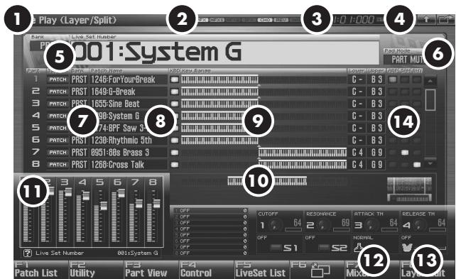
text_image
Play (Layer/Split) 2 3 4 5 6 7 8 9 10 11 12 13 14 15 16 17 18 19 20 21 22 23 24 25 26 27 28 29 30 31 32 33 34 35 36 37 38 39 40 41 42 43 44 45 46 47 48 49 50 51 52 53 54 55 56 57 58 59 60 61 62 63 64 65 66 67 68 69 70 71 72 73 74 75 76 77 78 79 80 81 82 83 84 85 86 87 88 89 90 91 92 93 94 95 96 97 98 99 100| Number | Explanation | Page |
| 1 | Indicates the current sound generator mode. | p. 39 |
| 2 | Indicates the on/off status of each effect.PFX Patch multi-effectMFX1 Multi-effect 1MFX2 Multi-effect 2IFX Input effectCHO ChorusREV ReverbMAS Mastering effect | p. 150 |
| 3 | Indicates the current location of the song, and the status of the sequencer. | p. 205 |
| 4 | The Menu/Exit/Shortcut buttons for the USB mouse. | p. 26 |
| 5 | Indicates/selects the bank, name, and number of the currently selected live set. | p. 60 |
| 6 | Indicates the pad mode. | p. 188 |
| 7 | Indicates/selects the type, bank, number, and name of the patch, rhythm set, or sample set for each part. | p. 61 |
| 8 | Indicates/changes the keyboard switch setting. | p. 61 |
| 9 | Indicates/changes the key range. | p. 62 |
| 10 | Indicates the key range that the Fantom-G6/G7/G8 can play. | - |
| 11 | Indicates the functions assigned to the realtime control sliders (1–8), knobs (1–4) and the S1/S2 switches.In Live mode, the sliders (1–8) indicate the levels of the 8 internal parts. (p. 62) | p. 142 |
| 12 | Indicates the function assigned to the D Beam controller and the response state of the D Beam controller. | p. 142 |
| 13 | Indicates the “Bend Mode” (p. 97) of the pitch bend lever. | p. 97 |
| 14 | Specifies the arpeggio part and pad part. | p. 61 |
Selecting a Live Set
The Fantom-G has two live set banks, including the User bank and Preset banks.
USER
This is the bank inside the Fantom-G which can be rewritten. Live Sets you create can be stored in this bank. You can store 512 live sets.
PRST (Preset)
This is the bank inside the Fantom-G which cannot be rewritten. However you may modify the settings of the currently selected live set, and then store the modified live set in User memory. The Fantom-G contains 512 preset live sets.
1. Press [LIVE].
![ROLAND FANTOM G8 - Press [LIVE]. - 1](/content/2025/01/130804/images/112d8d841b234d040add7256cb5df5c6e2b99ab94852612bb8e91b92817cd164.jpg)
text_image
MODE STUDIO LIVE SINGLE FAVORITE2. Press [CURSOR] to move the cursor to the live set bank.
![ROLAND FANTOM G8 - Press [CURSOR] to move the cursor to the live set bank. - 1](/content/2025/01/130804/images/130e480ed17b37c369b69fe5a3afc7956401508a8c77fc1a69d5fd46290fdf79.jpg)
text_image
Live set bank Live set number Live Play (Layer/S/RT) 001:System G PART MUTE G - B 3 G - B 33. Turn the VALUE dial, or press [INC] [DEC] to select a live set bank.
USER: User
PRST: Preset
4. Press [CURSOR] to move the cursor to the live set number.
5. Turn the VALUE dial or press [INC] [DEC] to select the live set number.
Selecting Live Sets from the List
You can display a list of live sets and select a live set from that list.
1. Press [LIVE].
2. Press [F5 (LiveSet List)].
The Live Set List screen appears.
![ROLAND FANTOM G8 - Press [F5 (LiveSet List)]. - 1](/content/2025/01/130804/images/3d35826c7fa832e3e8d6ec7c13b7b3220daa0af530bf67374ad9c06fdf916568.jpg)
text_image
Live Set List PRST 081-System 6 Rank Number Name PRST 081-System 6 Pulse PRST 082- Big & Proud Orch PRST 083- Within You Ethnic PRST 084- Dream Lead Lead PRST 085- CM Grand Piano Piano PRST 086- Dominique EP EP PRST 087- Guitar Heaven 1 Layer PRST 088- Nudrazz Synloss PRST 089- D-SB Magic Pad PRST 010- BPS TEMP BBPM FPS Menu PRST 011- Trancy Duo Techno PRST 012- Baroque Orch Orch F6 F7 F8 User Group Cancel Select3. Turn the VALUE dial or press ▲ or ▼ to select the live set.
4. Press [F8 (Select)] to close the Live Set List screen.
MEMO
Pressing [F6 (User Group)] will access the user group list screen, where you can register frequently-used studio sets.
→ “Registering a sound in the User Group screen” (p. 201)
MEMO
If you're using a USB mouse, you can click the keyboard symbol in the screen to access a virtual keyboard, which allows you to perform a keyword search.
Using the Live Play (Layer/Split) Screen
MEMO
When you modify the settings of a Live Set, the Live Play screen will indicate “.” The settings you modify are temporary, and will be lost when you turn off the power, switch the sound generator mode, or select a different sound. If you want to keep the modified sound, you must save it in the User bank (“Saving a Live/Studio Set You’ve Created (Write)” (p. 148)).
Selecting a Part
The currently selected part is called the "current part."
- Press [LIVE] to access the Live Play (Layer/Split) Screen.
- Use ▲ or ▼ to select the part.
The part number is shown in red for the selected part.
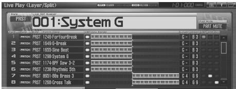
text_image
Live Play (Layer/Split) PRST 001:System G PRST PRST 1246 ForYourBreak G - B3 PRST PRST 1549 G-Break G - B3 PRST PRST 1555 Sine Beat G - B3 PRST PRST 1289 System 6 G - B3 PRST PRST 1174 BPF Saw 3-2 G - B3 PRST PRST 1289 Myrthmic Str G - B3 PRST PRST 6951 Bits Break 5 G - B3 PRST PRST 1289 Gross Talk G - B3 PRST MUTE G - B3 G - B3 G - B3 G - B3 G - B3 G - B3 G - B3 G - B3MEMO
As you continue pressing ▼, the screen will scroll downward, allowing you to select expansion board parts (if an expansion board is installed) or external MIDI output parts.
Selecting the Part that You want to Sound (Keyboard Switch)
Here's how to select the parts whose patch, rhythm set or sample set will sound. For each part, use the switch to specify whether that part will be played from the keyboard; this is called the "keyboard switch."
- In the Live Play (Layer/Split) screen, use [CURSOR] to move the cursor to the "KBD" area, and press [INC] to turn on the keyboard switch for the part(s) you want to play.
When you play the keyboard, you'll hear the part(s) whose keyboard switch you turned on. If all of the keyboard switches are off, you'll hear the current part.
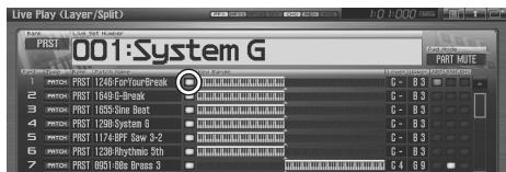
text_image
Live Play (Layer/Split) 001:System G 1 2 3 4 5 6 7 8 9 10 11 12 13 14 15 16 17 18 19 20 21 22 23 24 25 26 27 28 29 30 31 32 33 34 35 36 37 38 39 40 41 42 43 44 45 46 47 48 49 50 51 52 53 54 55 56 57 58 59 60 61 62 63 64 65 66 67 68 69MEMO
You can turn on the keyboard switch for more than one part.
MEMO
By pressing [F6 ☐ ] you can switch to a screen that shows only the parts whose keyboard switch is on.
NOTE
The current part will not sound if even one keyboard switch is on. If you want to hear the current part, turn off the keyboard switch for all parts.
Selecting the Part Played by the Pads
Use the pad switch to select the part whose rhythm set or sample set will be played by the pads.
- As described in the procedure for “Switching the Pad Mode (PAD MODE)” (p. 188), set the pad mode to either “1 SAMPLE PAD” or “2 RHYTHM.”
- In the Live Play (Layer/Split) screen, use [CURSOR] to move the cursor to the "SAM" or "RHY" field, and press [INC] to turn on the pad switch for the part that you want to play from the pads.
When you press the pads, you'll hear the part whose pad switch is on.
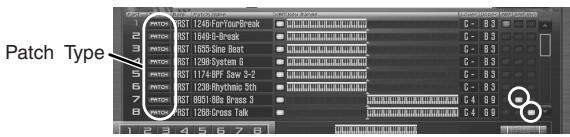
text_image
Patch Type 1 2 3 4 5 6 7 8 9 10 11 12 13 14 15 16 17 18 19 20 21 22 23 24 25 26 27 28 29 30 31 32 33 34 35 36 37 38 39 40 41 42 43 44 45 46 47 48 49 50 51 52 53 54 55 56 57 58 59 60 61 62 63 64 65 66 67 68 69NOTE
Make sure that the Patch Type is set to "SAMPLE" or "RHYTHM." If this is set to "PATCH," use [CURSOR] to move the cursor to the patch type, and turn the VALUE dial or press [INC] [DEC] to select "SAMPLE" or "RHYTHM."
MEMO
In the same way, you can use the “ARP” switch to specify the “Arpeggio Part Number” (p. 146).
Selecting the Sound for a Part
If you don't like the patch that is assigned to a part, it's easy to switch the patch.
- Select the part whose sound you want to switch.
- Press [F1 (Patch List)].
The Patch List screen will appear.
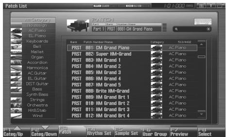
text_image
Patch List File Edit View E:\Design AC Piano EL Piano Keyboards Bell Mallet Organ Accordion Kanamika AC Guitar EL Guitar KST Guitar Box Synth Bass Strings Orchestra Hill&Scab Wind Patch Track Numbers Piano Category: 5124492 PRST B01: CM Grand Piano PRST B02: Super HM-Grand PRST B03: HM Grand 1 PRST B04: HM Grand 2 PRST B05: HM Grand 3 PRST B06: HM Grand 4 PRST B07: HM Grand 5 PRST B08: Brito HM-Grand PRST B09: HM Grand Art 1 PRST B10: HM Grand Art 2 PRST B11: HM Grand Art 3 PRST B12: HM Grand Art 4 Categ/Up Categ/Down Rhythm Set Sample Set User Group Preview Selectcf.
For details on using the Patch List screen, refer to “Selecting Patches from the List” (p. 49).
Combining and Playing Sounds Together (Layer)
In live mode you can play the sounds of all parts whose Keyboard Switch is on. Combining the parts will produce, thicker, fatter sounds.
You can create layers in the Live Play (Layer/Split) screen.
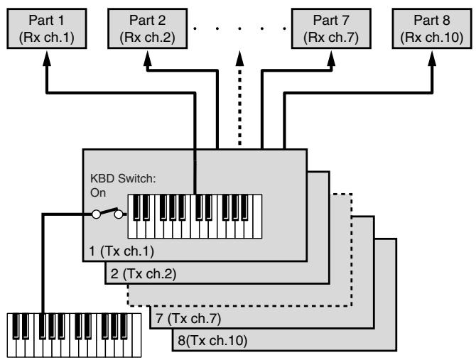
flowchart
graph TD
    A["Part 1 (Rx ch.1)"] --> B["KBD Switch: On"]
    C["Part 2 (Rx ch.2)"] --> B
    D["..."] --> B
    E["Part 7 (Rx ch.7)"] --> B
    F["Part 8 (Rx ch.10)"] --> B
    B --> G["1 (Tx ch.1)"]
    B --> H["2 (Tx ch.2)"]
    B --> I["7 (Tx ch.7)"]
    B --> J["8 (Tx ch.10)"]
    style B fill:#f9f,stroke:#333,stroke-width:2px
Rx ch.: Receive Channel
Tx ch.: Transmit Channel
- Press [LIVE] to access the Live Play (Layer/Split) Screen.
- Use [CURSOR] to move the cursor to "KBD," and press [INC] to turn on the keyboard switch for the parts that you want to hear.
If you press [DEC], the keyboard switch will turn off. The displayed keyboard shows the key range that will sound.
When you play the keyboard, you'll hear the parts whose keyboard switch is on.
- Repeat steps 2. to turn the Keyboard Switch on for all parts you want to play.
MEMO
The eight sliders in the Live Play (Layer/Split) screen correspond to the levels of the eight internal parts. You can control these by using the eight sliders on the Fantom-G's panel.
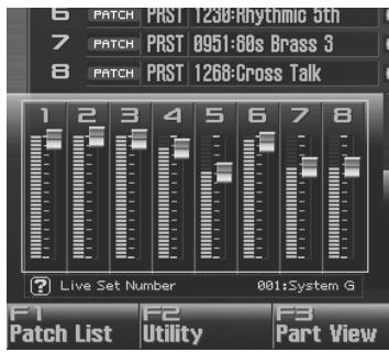
text_image
6 PATCH PRST T230-Rhythmic 5th 7 PATCH PRST 0951:80s Brass 3 8 PATCH PRST 1268-Gross Talk 1 2 3 4 5 6 7 8 Live Set Number 001:System G F1 F2 F3 Patch List Utility Part ViewPlaying Different Sounds in Different Areas of the Keyboard (Split)
In Live mode you can play (split) as many as 56 different patches across the keyboard.
| Part group | Number of parts |
| Internal | 8 |
| Expansion board 1 | Maximum 16* Depends on the expansion board |
| Expansion board 2 | Maximum 16* Depends on the expansion board |
| External MIDI output | 16 |
For instance, you can play strings in the lower range, piano in the upper range, and both sounds in the middle range.

natural_image
Pure piano keyboard layout without any text, numbers, or symbolsPart 1: Strings
[Non-Text]
Part 1 + Part 2:
(Strings + Piano)
Part 2: Piano
MEMO
A split performance is one application of a layer. Changing the key range of each part in the layer results in a split.
- Press [LIVE] to access the Live Play (Layer/Split) Screen.
- Use [CURSOR] to move the cursor to "KBD," and press [INC] to turn on the keyboard switch for the parts you want to hear.
- Move the cursor to "Lower" and set the lower limit of the keys that will play the part. Move the cursor to "Upper" and set the upper limit of the keys that will play the part.
To specify the key range, you can turn the VALUE dial or use [INC] [DEC]. The displayed keyboard indicates the range of keys for which each part will sound.
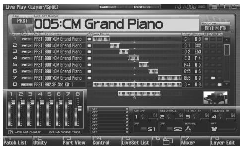
text_image
Live Play (Layer/Split) 005-CM Grand Piano 1 2 3 4 5 6 7 8 9 10 11 12 13 14 15 16 17 18 19 20 21 22 23 24 25 26 27 28 29 30 31 32 33 34 35 36 37 38 39 40 41 42 43 44 45 46 47 48 49 50 51 52 53 54 55 56 57 58 59 60 61 62 63 64 65 66 67 68 69 70 71 72 73 74 75 76 77 78 79 80 81 82 83 84 85 86 87 88 89 90 91 92 93 94 95 96 97 98 99 100Value: Key Range Lower: C-1–UPPER
Key Range Upper: LOWER-G9
TIP
By specifying sections for different parts so that they overlap each other, you can combine two or more parts only in a specific section.
Using the Live Set Part Mixer Screen
The Live Set Part Mixer screen lets you adjust the level and effect settings of each part just as if you were using a mixer.
Here's how to access the Live Set Part Mixer screen.
1. Press [LIVE].
![ROLAND FANTOM G8 - Press [LIVE]. - 1](/content/2025/01/130804/images/ead417404ade479c019c52ddee9b245b7117ecb3ba613b353fbf2aad39245659.jpg)
text_image
MODE STUDIO LIVE SINGLE FAVORITEYou will enter Live Mode, and the Live Play (Layer/Split)
Screen appears.
2. Press [F7 (Mixer)].
The Live Set Part Mixer screen will appear.
![ROLAND FANTOM G8 - Press [F7 (Mixer)]. - 1](/content/2025/01/130804/images/5280565dd3af69edd36424685f90d5b7107a35ad59b46ba146c4b27754214fe3.jpg)
text_image
Live Set Mixer Audio Track Interval EXP 1 EXP 2 External Print Mute PRST 001 System G Internal Part 1 PRST 1248 Fan/YearBreak Multi Sw Chorus Send Reverb Send Fan Level Live Set Number 001 System G Patch List Exit LiveSet List F4 F5 F6 F7 F8F-key operations in the Live Set Part Mixer screen
| F-key | Explanation | Page |
| F1Patch List | Selects the patch sound assigned to each part. | p. 61 |
| F4Exit | Returns to the previous screen. | - |
| F5LiveSet List | Selects a live set. | p. 60 |
| F6 | Switches between the Mixer 1/2 screens. | - |
| F7 | Selects the eight parts that will be controlled by the sliders. A frame is shown around the currently selected parts. By moving this frame outside the screen, you can switch the part group that is displayed. | - |
| F8 |
MEMO
In this screen, the name of the parameter selected by the cursor is shown in the “?” area at the lower left of the screen. Here you can also check the value of the current setting.
MEMO
By pressing the [F7 ◀] or [F8 ▶] key several times, you can move the screen to the left or right, switching the displayed part group.
| Part Group | Explanation |
| Audio Track | Audio tracks of the song |
| Internal | Internal (internal sound generator) |
| EXP 1 | Expansion board 1 |
| EXP 2 | Expansion board 2 |
| External | External MIDI output |
MEMO
You can switch the part group by holding down [SHIFT] and
pressing ◀ or ▶.
Editing the Part Settings
In the Live Set Part Mixer screen you can set the following parameters for each part.
MEMO
Use [F6 ☐] to switch between Mixer 1/2.
- Use [CURSOR] to move the cursor to the parameter you want to edit.
- Turn the VALUE dial or use [INC] [DEC] to set the desired value.
| Mixer1/2 | Parameter | Page |
| Internal | ||
| Mixer1 | Mute Switch | p. 134 |
| Part Chorus Send Level | p. 136 | |
| Part Reverb Send Level | p. 137 | |
| Part Pan | p. 134 | |
| Part Level | p. 134 | |
| Mixer2 | Part Output Level | p. 136 |
| Part Output Assign | p. 136 | |
| Recording Switch | *1 | |
| Keyboard Switch | p. 135 | |
| Arpeggio Part | p. 146 | |
| Sample Pad Part | p. 146 | |
| Rhythm Pad Part | p. 146 | |
| EXP 1, EXP 2 | ||
| Mixer1 | Mute Switch | p. 134 |
| Part EFX1 Send Level | p. 137 | |
| Part EFX2 Send Level | p. 137 | |
| Part Pan | p. 134 | |
| Part Level | p. 134 | |
| Exp.1/2 Master Chorus Send Level | ||
| Exp.1/2 Master Reverb Send Level | ||
| Exp.1/2 Master Pan | ||
| Exp.1/2 Master Level | ||
| Mixer2 | Part Output Level | p. 136 |
| Part Output Assign | p. 136 | |
| Keyboard Switch | p. 135 | |
| Arpeggio Part | p. 146 | |
| Rhythm Pad Part | p. 146 | |
| Exp.1/2 Master Output Level | ||
| Exp.1/2 Master Output Assign | ||
| Exp.1/2 Master Recording Switch | ||
| External | ||
| Mixer1 | External Pan | p. 135 |
| External Level | p. 135 | |
| Mixer2 | Keyboard Switch | p. 135 |
| Arpeggio Part | p. 146 | |
| Rhythm Pad Part | p. 146 | |
| Audio Track | ||
| Mixer1 | Mute Switch | |
| Part Chorus Send Level | ||
| Part Reverb Send Level | ||
| Part Pan | ||
| Part Level | ||
| Mixer2 | Part Output Assign | |
| Recording Switch | *1 | |
*1 Parts whose Recording Switch is off will not be recorded to audio tracks of the sequencer. (Nor will they be sampled.) You can turn this off for a part that you want to hear, but not record as audio. Normally you will leave this turned on. Effects will not be applied to a part whose Recording Switch is off.
Using the Layer Edit Screen
In general, the Layer Edit screen operates in the same way as the Live Play (Layer/Split) screen, but you can use the F3–F6 keys to instantly switch between the displayed part groups.
| F-key | Explanation |
| F3 Internal | Internal (internal sound generator) |
| F4 EXP 1 | Expansion board 1 |
| F5 EXP 2 | Expansion board 2 |
| F6 External | External MIDI output |
Here's how to access the Layer Edit screen.
1. Press [LIVE].
![ROLAND FANTOM G8 - Press [LIVE]. - 1](/content/2025/01/130804/images/059cd405264c3e0a1aa684348d83a1a5c77da592a14dd5b8045046cc3be9d843.jpg)
text_image
MODE STUDIO LIVE SINGLE FAVORITEYou will enter Live Mode, and the Live Play (Layer/Split) Screen appears.
![ROLAND FANTOM G8 - Press [LIVE]. - 2](/content/2025/01/130804/images/986dfe2f656dbf32c0a5bae28502690b729d9d4a6979c06a828bc38757f93d3a.jpg)
text_image
Live Play (Layer/Split) PRST 001:System G 1 2 3 4 5 6 7 8 9 10 11 12 13 14 15 16 17 18 19 20 21 22 23 24 25 26 27 28 29 30 31 32 33 34 35 36 37 38 39 40 41 42 43 44 45 46 47 48 49 50 51 52 53 54 55 56 57 58 59 60 61 62 63 64 65 66 67 68 69 70 71 72 73 74 75 76 77 78 79 80 81 82 83 84 85 86 87 88 89 90 91 92 93 94 95 96 97 98 99 1002. Press [F8 (Layer Edit)].
The Layer Edit screen will appear.
![ROLAND FANTOM G8 - Press [F8 (Layer Edit)]. - 1](/content/2025/01/130804/images/b176a45aa39b2def08d279c005c52eb7bc0dc4541280e4bd3d7b193d4c4449cf.jpg)
Selecting the Sound for a Part
If you don't like the patch that is assigned to a part, it's easy to switch the patch.
- Select the part whose sound you want to switch.
- Press [F1 (Patch List)].
The Patch List screen will appear.
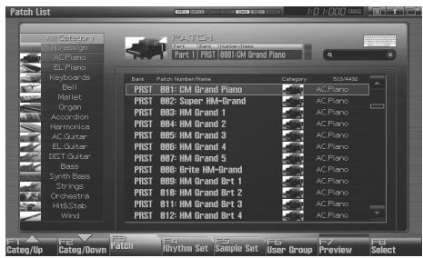
text_image
Patch List Cate/Up Cate/Down Catch Rhythm Set Sample Set User Group Preview Select
For details on using the Patch List screen, refer to “Selecting Patches from the List” (p. 49).
Editing the Part Settings
In the Layer Edit screen you can set the following parameters for each part.
| Parameter | Shown in the screen as |
| Keyboard Switch (p. 135) | KBD |
| Patch Type (p. 134) | Type |
| Patch Bank (p. 134) | Bank |
| Patch Number (p. 134) | Patch Name |
| Keyboard Range Lower (p. 135) | Lower |
| Keyboard Range Upper (p. 135) | Upper |
| Arpeggio Part (p. 146) | ARP |
| Sample Pad Part / Rhythm Pad Part (p. 146) | SAM/RHY |
- Press [LIVE], and then press [F8 (Layer Edit)] to access the Layer Edit screen.

Performing with the Arpeggio
cf.
For details on using the Arpeggio, refer to “Playing Arpeggios” (p. 78).
Performing with the Realtime Controllers and D Beam Controller
cf.
For details on the setting, refer to “Selecting the Parameter Controlled by the Realtime Controllers or D Beam Controller (Control Setting)” (p. 142).
Setting Effects
cf.
For details regarding effect settings, refer to the pages shown below.
• “Making Effect Settings” (p. 151)
- “Applying Effects in Live Mode” (p. 151)
Adjusting the Master Level
cf.
For details, refer to "How Do I Adjust the Volume?" (p. 298)
Making Detailed Settings for a Live Set
cf.
Refer to "Creating a Live/Studio Set" (p. 132).
Studio mode is what you'll use when recording a song. It provides sixteen parts, and allows you to assign a patch (or rhythm set or sample set) to each of these parts, thus allowing you to use sixteen different sounds simultaneously.
You can use the mixer screen to adjust the level and pan for each of the sixteen parts.
MEMO
In addition to sixteen parts of the internal sound generator, Studio mode allows you to simultaneously use parts of an expansion board (the number of parts depends on the expansion board) and external MIDI output parts.
| Number of parts | |
| Internal | 16 |
| Expansion board 1 | Maximum 16* Depends on the expansion board |
| Expansion board 2 | Maximum 16* Depends on the expansion board |
| External MIDI output | 16 |
A Studio set contains a patch (rhythm set, sample set) assignment for each part, as well as settings such as volume and pan for each part. When you play the keyboard, you'll hear the current part.
NOTE
Every part whose keyboard switch (p. 69) is on will sound. We recommend that you leave the keyboard switch turned off. If it is on, parts other than the current part will also sound, and this is probably not what you want when you're creating a song.
Recording a song
cf.
For details on recording a song, refer to “Recording MIDI” (p.217).
Displaying Studio Play Screen
The Studio Play screen allows you to adjust the level and effect settings of each part just as if you were using a mixer.
To access the Studio Play Screen, use the following procedure.
1. Press [STUDIO].
![ROLAND FANTOM G8 - Press [STUDIO]. - 1](/content/2025/01/130804/images/f05d4b61917fa42f0a99b53b453705c240c89a1e672bd5286bcaf978f213f738.jpg)
text_image
MODE STUDIO LIVE SINGLE FAVORITEYou will enter Studio Mode, and the Studio Play Screen appears.
![ROLAND FANTOM G8 - Press [STUDIO]. - 2](/content/2025/01/130804/images/65ff8b390e86b5ba94199ad439e74af68ea93645bf6baa945aee998a183a8661.jpg)
text_image
Studio Play Audio Track Internal EXP 1 EXP 2 External RUTTIM PRST BB1-Standard Set Interval Part 1 ERROR PRST BB1-6-Brand HEDD1 1 2 3 4 5 6 7 8 9 10 11 12 13 14 15 16 Hute Sw Chorus Send Revers Send Pan Level Part Level (CCB 7) 100 F1 Patch List F2 Utility Part View F3 Control Studio List F6 F7 F8F-key operations in the Studio Play screen
| F-key | Explanation | Page |
| F1Patch List | Selects the patch assigned to each part. | p. 68 |
| F2Utility | Makes settings common to the entire studio set. | p. 132 |
| F3Part View | Makes detailed settings for each part of the studio set. | p. 133 |
| F4Control | Selects the parameters that will be controlled by the realtime controllers and the D Beam controller. | p. 70 |
| F5Studio List | Selects a studio set. | p. 68 |
| F6 | Switches between the Mixer1/2 screens. | - |
| F7◀ | Selects the eight parts that will be controlled by the slider. A frame is shown around the currently selected parts. By moving this frame outside the screen, you can switch the part group that is displayed. | - |
| F8▶ |
MEMO
In the Studio Play screen, pressing the [F6 ☐] a number of times will display the controller status (the functions assigned to sliders 1–8, knobs 1–4, switches S1/S2, and the D Beam controller, and the Bend Mode of the pitch bend lever).
Pressing [F6 ☐] cycles you through the screens as follows.
MIXER 1→MIXER 2→Controller display→MIXER 1...
* The controller display will not appear if audio tracks are shown in the mixer.
Functions in the Studio Play Screen
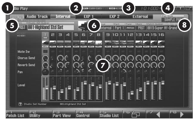
text_image
Audio Play Audio Track Internal EXP 1 EXP 2 External PART NO. 1 0 1 0 0 1 1 1 1 1 1 1 1 1 PART RST 001-Highland Std Set MUTE Sw Chorus Send Reverb Send Pan Level Studio Set Number 001-Highland Std Set F1 Patch List F2 Utility F3 Part View F4 Control F5 Studio List F6 F7 F8 SAMPLE PRO PART RST PRST 0015-Super NY-Brand| Number | Explanation | Page |
| 1 | Indicates the current sound generator mode. | p. 39 |
| 2 | Indicates the on/off status of each effect.PFX Patch multi-effectMFX1 Multi-effect 1MFX2 Multi-effect 2IFX Input effectCHO ChorusREV ReverbMAS Mastering effect | p. 150 |
| 3 | Indicates the current location of the song, and the status of the sequencer. | p. 205 |
| 4 | The Menu/Exit/Shortcut buttons for the USB mouse. | p. 26 |
| 5 | Indicates/selects the bank, number, and name of the currently selected studio set. | p. 67 |
| 6 | Indicates/selects the part group, part number, bank, number, and name of the patch, rhythm set, or sample set for the current part. | p. 68 |
| 7 | Accesses the mixer screen. | p. 69 |
| 8 | Indicates the pad mode. | p. 188 |
Switching the Displayed Part Group
In addition to the internal (internal sound generator) parts, the Studio Play screen allows you to switch the view to see audio tracks, expansion board parts, or external MIDI output parts.
-
Press [STUDIO] to access the Studio Play screen.
-
Press the [F7 ◀] or [F8 ▶] key several times to move the screen to left or right, selecting the part group that is displayed.
| Part group | Explanation |
| Audio Track | Audio tracks in the song |
| Internal | Internal (internal sound generator) |
| EXP 1 | Expansion board 1 |
| EXP 2 | Expansion board 2 |
| External | External MIDI output |
MEMO
You can switch the part group by holding down [SHIFT] and pressing ◀ or ▶.
Selecting a Studio Set
The Fantom-G has two studio set banks, including the User bank and Preset banks.
USER
This is the bank inside the Fantom-G which can be rewritten. Studio Sets you create can be stored in this bank. You can store 128 studio sets.
PRST (Preset)
This is the bank inside the Fantom-G which cannot be rewritten. However you may modify the settings of the currently selected studio set, and then store the modified studio set in User memory. The Fantom-G contains 8 preset studio sets.
- Press [STUDIO].
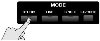
text_image
MODE STUDIO LIVE SINGLE FAVORITE- Press [CURSOR] to move the cursor to the studio set bank.
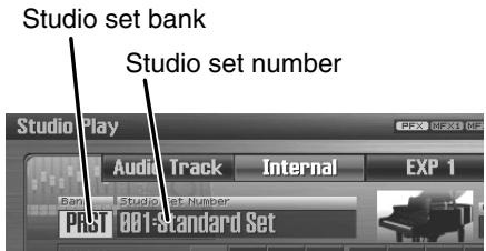
text_image
Studio set bank Studio set number Studio Play Audio Track Internal EXP 1 Banc Studio Set Number PRST 001-Standard Set- Turn the VALUE dial, or press [INC] [DEC] to select a studio set bank.
USER: User
PRST: Preset
-
Press [CURSOR] to move the cursor to the studio set number.
-
Turn the VALUE dial or press [INC] [DEC] to select the studio set number.
Selecting Studio Sets from the List
You can display a list of studio sets and select a studio set from that list.
1. Press [STUDIO].
![ROLAND FANTOM G8 - Press [STUDIO]. - 1](/content/2025/01/130804/images/c9bbf939227d377bb925c718da8f77cc57cbc0c48c707e7756078c3d96eabf77.jpg)
text_image
MODE STUDIO LIVE SINGLE FAVORITE2. Press [F5 (Studio List)].
The Studio Set List screen appears.
![ROLAND FANTOM G8 - Press [F5 (Studio List)]. - 1](/content/2025/01/130804/images/d21431ce94239d5dc38d9d56dad9ed6d48275420c3c5e639a5201e3d0372861e.jpg)
text_image
Studio Set List PRST 081 Standard Set Rank Name Name USER 125: INIT STUDIO SET USER 126: INIT STUDIO SET USER 127: INIT STUDIO SET USER 128: INIT STUDIO SET PRST 081: Standard Set PRST 082: R&B Studio Set PRST 083: Jazz Studio Set PRST 084: Latin Studio Set PRST 085: Orchestra Set PRST 086: Euro Dance Set PRST 087: Rock Studio Set PRST 088: GM2 Template Initial Standard Studio Set Initial RBB Studio Set Initial Jazz Studio Set Small Latin Studio Set Initial Orchestra Set Euro Dance Sample Set Initial Rock Studio Set F6 F7 F8 User Group Cancel Select- Turn the VALUE dial or press ▲ or ▼ to select the studio set.
4. Press [F8 (Select)] to close the Studio Set List screen.
MEMO
By pressing [F6 (User Group)] you can access the user group list screen, where you can register frequently-used studio sets.
→ “Registering a sound in the User Group screen” (p. 201)
MEMO
If you're using a USB mouse, you can click the keyboard symbol in the screen, and then use the virtual keyboard in the screen to perform a keyword search.
Using the Studio Play Screen
MEMO
When you modify the settings of a Studio Set, the Studio Play screen will indicate “.” Settings you modify are temporary, and will be lost if you turn off the power, switch the tone generator mode, or select a different sound. If you want to keep the modified sound, you must save it in the User bank (“Saving a Live/Studio Set You’ve Created (Write)” (p. 148)).
Selecting a Part
The currently selected part is called the “current part.”
1. Press [STUDIO].
The Studio Play screen appears.
![ROLAND FANTOM G8 - Press [STUDIO]. - 1](/content/2025/01/130804/images/148a82e2ce431205f2e29122824d3936f6c82f90b3ed4c2a3d01ac4739e0e6d9.jpg)
text_image
MODE STUDIO LIVE SINGLE FAVORITE2. Use [CURSOR] to select the part.
The selected part is highlighted.
![ROLAND FANTOM G8 - Use [CURSOR] to select the part. - 1](/content/2025/01/130804/images/de165566a81531a93b2d91c9ca5434491be8fa48d1d2730b2c16dd75fe28d93a.jpg)
text_image
Studio Play Audio Track Internal EXP 1 EXP 2 External PAST 601-Standard Set Internal Part 1 PAST 601-Standard Set HOLDEN 1 2 3 4 5 6 7 8 9 10 11 12 13 14 15 16 Hertz 601-Standard Set Mute Sw Chorus Send Revers Send Pan Level Part Level (CCR 7) 100 F1 F2 F3 F4 F5 F6 F7 F8 Patch List Utility Part View Control Studio List3. Play the keyboard, and you'll hear the current part.
Selecting the Sound for a Part
If you don't like the patch that is assigned to a part, it's easy to switch the patch.
1. Select the part whose sound you want to switch.
2. Press [F1 (Patch List)].
The Patch List screen will appear.
cf.
For details on using the Patch List screen, refer to “Selecting Patches from the List” (p. 49).
Selecting the Part that You Want to Sound (Keyboard Switch)
Here's how to select the part that you want to play from the keyboard. Each part has a setting called the "keyboard switch" that determines whether that part will sound in response to the keyboard. If this is turned off for all parts, the current part will sound.
TIP
When you're recording a song, we recommend that you turn the keyboard switch off for all parts. If this is turned on for any parts, the keyboard will not play the current part, which would not be convenient for song production.
- Press [STUDIO].
- Press [F6 □].
- Use [CURSOR] to move the cursor to the "Keyboard Sw" field, and press [INC] to turn the keyboard switch on.
When you play the keyboard, you'll hear the parts whose keyboard switch is on. If the keyboard switch is turned off for all parts, you'll hear the current part.
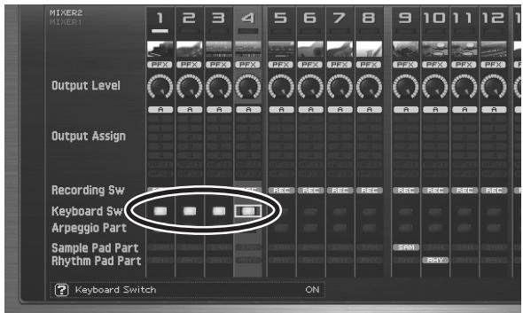
text_image
MIXER2 RIVER1 1 2 3 4 5 6 7 8 9 10 11 12 PFX PFX PFX PFX PFX PFX PFX PFX PFX Output Level Output Assign Recording Sw Keyboard Sw Arpeggio Part Sample Pad Part Rhythm Pad Part ? Keyboard Switch ONMEMO
You can turn on the keyboard switch for multiple parts.
Editing the Part Settings
In the Studio Play screen you can set the following parameters for each part.
- Press [STUDIO].
- Use [CURSOR] to move the cursor to the parameter you want to edit.
- Turn the VALUE dial or use [INC] [DEC] to set the desired value.
MEMO
In this screen, the name of the parameter selected by the cursor is shown in the “?” area at the lower left of the screen. The current value is also shown here.
MEMO
For details on how to switch between part groups, refer to “Switching the Displayed Part Group” (p. 67).
MEMO
Use [F6 ☐] to switch between Mixer 1/2.
| Mixer1/2 | Parameter | Page |
| Internal | ||
| Mixer1 | Mute Switch | p. 134 |
| Part Chorus Send Level | p. 136 | |
| Part Reverb Send Level | p. 137 | |
| Part Pan | p. 134 | |
| Part Level | p. 134 | |
| Mixer2 | Part Output Level | p. 136 |
| Part Output Assign | p. 136 | |
| Recording Switch | *1 | |
| Keyboard Switch | p. 135 | |
| Arpeggio Part | p. 146 | |
| Sample Pad Part | p. 146 | |
| Rhythm Pad Part | p. 146 | |
| EXP 1, EXP 2 | ||
| Mixer1 | Mute Switch | p. 134 |
| Part EFX1 Send Level | p. 137 | |
| Part EFX2 Send Level | p. 137 | |
| Part Pan | p. 134 | |
| Part Level | p. 134 | |
| Exp.1/2 Master Chorus Send Level | ||
| Exp.1/2 Master Reverb Send Level | ||
| Exp.1/2 Master Pan | ||
| Exp.1/2 Master Level | ||
| Mixer2 | Part Output Level | p. 136 |
| Part Output Assign | p. 136 | |
| Keyboard Switch | p. 135 | |
| Arpeggio Part | p. 146 | |
| Rhythm Pad Part | p. 146 | |
| Exp.1/2 Master Output Level | ||
| Exp.1/2 Master Output Assign | ||
| Exp.1/2 Master Recording Switch | ||
| External | ||
| Mixer1 | External Pan | p. 135 |
| External Level | p. 135 | |
| Mixer2 | Keyboard Switch | p. 135 |
| Arpeggio Part | p. 146 | |
| Rhythm Pad Part | p. 146 | |
| Audio Track | ||
| Mixer1 | Mute Switch | |
| Part Chorus Send Level | ||
| Part Reverb Send Level | ||
| Part Pan | ||
| Part Level | ||
| Mixer2 | Part Output Assign | |
| Recording Switch | *1 | |
*1 Parts whose Recording Switch is off will not be recorded to audio tracks of the sequencer. (Nor will they be sampled.) You can turn this off for a part that you want to hear, but not record as audio. Normally you will leave this turned on. Effects will not be applied to a part whose Recording Switch is off.
Performing with the Arpeggio
cf.
For details on using the Arpeggio, refer to “Playing Arpeggios” (p. 78).
Performing with the Realtime Controllers and D Beam Controller
cf.
For details on the setting, refer to “Selecting the Parameter Controlled by the Realtime Controllers or D Beam Controller (Control Setting)” (p. 142).
Setting Effects
cf.
For details regarding effect settings, refer to the pages shown below.
• “Making Effect Settings” (p. 151)
- “Applying Effects in Studio Mode” (p. 154)
Adjusting the Master Level
cf.
For details, refer to “How Do I Adjust the Volume?” (p. 298).
Making Detailed Settings for a Studio Set
cf.
Refer to "Creating a Live/Studio Set" (p. 132).
03: Sound Generator, Section 2 (Controlling Sounds)
This chapter explains the realtime controllers, the arpeggiator, and the chord memory function.
• Real Time Controller ...... p. 72
• Arpeggios.... p. 78
- Chord Memory ...... p. 81
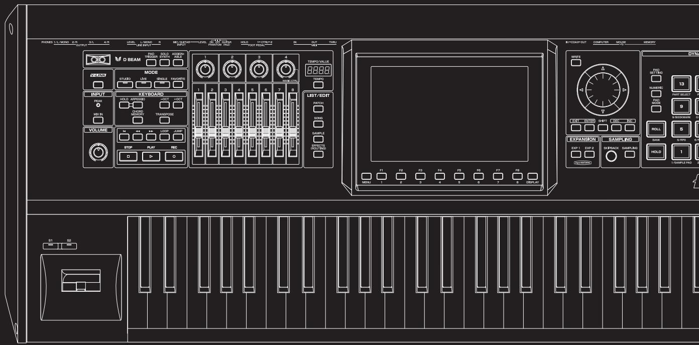
text_image
PROKES L/L MISO 2/R OUTPUT 3/L 4/R LEVEL L-MISO 5 MECUTAIN LEVEL 6 M.1.2 GURAN HOLD I-CTR=2 IN OUT TURU D BEAM RAD TRIGGER SWORD ASSEMB- MODE STUDIO LIVE SINGLE FAUCERS INPUT PEAK HOLD APPROXED 3OCT 4OCT CHORD MEOCON TRANSPOSE VOLUME STOP PLAY REC LIST/EDIT MATCH DOYS SAMPLE CAPSIC (RDT/RDS) EXPANSION SAMPLING EXP 1 EXP 2 SREBACK SAMPLING HOLD 1 SAMPLE RAD 2 S1 SB MINI 1 2 3 4 5 6 7 8 DISPLAY IN-COMP-OUT COMPUTER MOUSE MEMORY WIFE PAD SETTING FLAVENIX 13 FAST SELECT 9 BLOODMARK ON ROLL 5 SANK 6-RP0 6-RP1 F1 F2 F3 F4 F5 F6 F7 F8 S1 SBYou can use the D Beam controller, realtime controllers, assignable switches or a pedal to modify the sound while you perform.
MEMO
Here we will explain the procedures and settings for using these functions in Single mode. The operations are the same in Live Mode/Studio Mode.
Waving Your Hand Over the D Beam to Modify the Sound (D Beam Controller)
The D Beam controller can be used simply by waving your hand over it. It can be used to apply various effects, depending on the function that is assigned to it. You can also create effects in which the sound changes instantaneously, in a way that would not be possible by operating a knob or the bender lever. On the Fantom-G, the D Beam controller can be used not only to modify the sounds assigned to the Keyboard part or Pad part, but also to control the pitch of a monophonic (solo) synthesizer sound.
1. Access the Single Play screen (p. 46).
The following area of the screen is the D Beam controller display area.
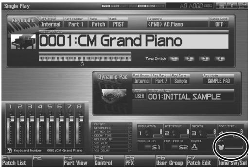
text_image
Single Play Keyboard Part Number Part Number Page Bars Catalogue Cate Lock Internal Part 1 Patch PRST (PND) AC.Piano OFF 0001:CM Grand Piano Tone Switch Dynamic Pad Part Group Part Part Pack Wave Fats Mode Internal Part 7 Sample SAMPLE PRO USER: 001:INITIAL SAMPLE 1 2 3 4 5 6 7 8 Keyboard Number 0001:CM Grand Piano F1 F2 F3 F4 F5 F6 F7 Patch List Part View Control PFX User Group Patch Edit Tone SW/Sel2. Press either the D BEAM [PAD TRIGGER], [SOLO SYNTH], or [ASSIGNABLE] button to turn on the D Beam controller.
- PAD TRIGGER button: Use the D Beam controller to play sounds instead of striking the pads.
- SOLO SYNTH button: Lets you use the D Beam as a monophonic synthesizer.
- ASSIGNABLE button: Operates the function assigned to the D Beam controller.
3. While you play the keyboard or pads to produce sound, place your hand above the D Beam controller and move it slowly up and down.
An effect will be applied to the sound, depending on the function that is assigned to the D Beam controller.
4. To turn off the D Beam controller, once again press the button you pressed in step 2 so the indicator goes out.
MEMO
If live mode is selected, the D Beam controller on/off setting is saved for each live set as part of the live set settings. Similarly in studio mode, this setting is saved as part of the studio set.
The usable range of the D Beam controller
The following diagram shows the usable range of the D Beam controller. Waving your hand outside this range will produce no effect.
The response of the D Beam Controller can also be checked in the "D Beam" area of the display. This is displayed graphically as a bar that lengthens as you move your hand closer, and shortens as you move your hand away.

NOTE
The usable range of the D Beam controller will become extremely small when used under strong direct sunlight. Please be aware of this when using the D Beam controller outside.
NOTE
The sensitivity of the D Beam controller will change depending on the amount of light in the vicinity of the unit. If it does not function as you expect, adjust the sensitivity as appropriate for the brightness of your location. Increase this value will raise the sensitivity (p. 291).
Making Settings for the D Beam Controller
Pad Trigger (Pad-related settings)
You can use the D Beam controller to control the pads as an alternative to striking the pads themselves.
- Hold down [SHIFT] and press D BEAM [PAD TRIGGER].
- Move the cursor to the parameter that you want to set, and turn the VALUE dial or press [INC] [DEC] to make the setting.
- Press [EXIT] to close the window.
Beam Trigger Pad
Specifies the pad number affected by the D Beam.
Value: Pad 1–Pad 16
Beam Trigger Velo (Beam Trigger Velocity)
Specifies the strength of the pad sound played by the D Beam controller.
Value: 1–127
Beam Trigger Mode
This specifies how the D Beam will behave when it is obstructed. If this is set to MOMENTARY, the parameter will be on only while the D Beam is obstructed, and will turn off when you stop obstructing it. If this is set to LATCH, the parameter will alternately be switched on/off each time you obstruct the D Beam.
Value: MOMENTARY, LATCH
TIP
If Live mode is selected, PAD trigger settings are saved independently for each live set as part of the live set settings. This lets you create live sets that make effective use of controller settings. Similarly in studio mode, this setting is saved as part of the studio set.
TIP
If Single mode is selected, this is saved as part of the system settings. If you want to save the settings, press [F7 (Sys Write)].
Solo Synth
On the Fantom-G you can play a monophonic synthesizer whose pitch is controlled by the D Beam.
- Hold down [SHIFT] and press D BEAM [SOLO SYNTH].
- Move the cursor to the parameter that you want to set, and turn the VALUE dial or press [INC] [DEC] to make the setting.
- If you want to save the settings, press [F7 (Sys Write)]. Press [EXIT] to close the Solo Synth window.
TIP
Setting for the Solo Synth are saved for system settings.
MEMO
In this screen, the name of the parameter selected by the cursor is shown in the “?” area in the lower left of the screen. The current value of the setting is also shown here.
OSC 1/2 Waveform
Select the waveform. SAW is a sawtooth wave, and SQR is a square wave.
Value: SAW, SQR
OSC 1/2 Pulse Width
Specifies the pulse width of the waveform. By cyclically modifying the pulse width you can create subtle changes in the tone.
* The Pulse Width is activated when "SQR" is selected with OSC1/2 waveform.
Value: 0–127
LFO Osc 1 Pulse Width Depth
Specifies the depth to which the LFO will modulate the pulse width of the OSC1 waveform.
* The Pulse Width is activated when "SQR" is selected with waveform.
Value: -63- +63
LFO Osc 2 Pulse Width Depth
Specifies the depth to which the LFO will modulate the pulse width of the OSC2 waveform.
* The Pulse Width is activated when "SQR" is selected with waveform.
Value: -63- +63
Modifying the Sound in Real Time
LFO Osc 1 Pitch Depth
Specifies the depth to which the LFO will modulate the OSC1 pitch.
Value: -63- +63
LFO Osc 2 Pitch Depth
Specifies the depth to which the LFO will modulate the OSC2 pitch.
Value: -63- +63
OSC 1/2 Coarse Tune
Adjusts the pitch of the tone's sound up or down in semitone steps (+/-4 octaves).
Value: -48- +48
OSC 1/2 Fine Tune
Adjusts the pitch of the tone's sound up or down in 1-cent steps (+/-50 cents).
Value: -50- +50
OSC Sync Switch
Turning this switch on produces a complex sound with many harmonics. This is effective when the OSC1 pitch is higher than the OSC2 pitch.
Value: ON, OFF
OSC2 Level
Adjust the OSC2 level.
Value: 0–127
Filter Type
Selects the type of filter. A filter modifies the brightness or thickness of the sound by cutting a specific frequency range.
Value
OFF: No filter is used.
LPF: Low Pass Filter. This reduces the volume of all frequencies above the cutoff frequency (Cutoff Freq).
BPF: Band Pass Filter. This leaves only the frequencies in the region of the cutoff frequency, and cuts the rest.
HPF: High Pass Filter. This cuts the frequencies in the region below the cutoff frequency.
PKG: Peaking Filter. This emphasizes the frequencies in the region of the cutoff frequency.
Cutoff
Selects the frequency at which the filter begins to have an effect on the waveform's frequency components.
Value: 0–127
Resonance
Emphasizes the portion of the sound in the region of the cutoff frequency, adding character to the sound.
Value: 0–127
LFO Rate
Adjusts the modulation rate, or speed, of the LFO.
Value: 0–127
Range (Solo synth range)
Specifies the range in which the pitch of the solo synth will vary.
Value: 2 OCT, 4 OCT, 8 OCT
Chorus Send Level
Sets the level of the signal sent to chorus.
Value: 0–127
Reverb Send Level
Sets the level of the signal sent to reverb.
Value: 0–127
Level
Sets the volume.
Value: 0–127
Assignable
You can assign various functions to the D Beam controller and apply a wide range of effects to the sound in real time.
- Hold down [SHIFT] and press D BEAM [ASSIGNABLE].
- Move the cursor to the parameter that you want to set, and turn the VALUE dial or press [INC] [DEC] to make the setting.
- Press [EXIT] to close the window.
Type (Assignable Type)
Specifies the function controlled by the D Beam controller.
Value
OFF: Off
CC01-31, CC32(OFF), 33-95:
Control Change
AFTERTOUCH: Aftertouch
BEND UP: Controls the pitch as specified by the "Pitch Bend Range Up" setting (p. 96).
BEND DOWN: Controls the pitch as specified by the "Pitch Bend Range Down" setting (p. 96).
ARPEGGIO ACCENT: Arpeggio accent rate
ARPEGGIO SHUFFLE: Arpeggio shuffle rate
ARPEGGIO OCT UP: The range in which the arpeggio is sounded will rise in steps of an octave.
ARPEGGIO OCT DOWN: The range in which the arpeggio is sounded will lower in steps of an octave.
Range Min
Specify the lower limit of the range of the D Beam controller.
Value: 0–127
Range Max
Specify the upper limit of the range of the D Beam controller. By setting Range Max below Range Min you can invert the range of change.
Value: 0–127
TIP
If Live mode is selected, The settings for the ASSIGNABLE are saved independently for each live set as part of the live set settings. This lets you create live sets that make effective use of controller settings. Similarly in studio mode, this setting is saved as part of the studio set.
TIP
If Single mode is selected, this is saved as part of the system settings. If you want to save the settings, press [F7 (Sys Write)].
Using Knobs, Sliders or S1/S2 Buttons to Modify the Sound (Realtime Controller)
You can use the knobs, sliders and [S1] [S2] buttons to modify the sound in real time.
1. Access the Single Play screen (p. 46).
The “Realtime Control” area shows the function that is assigned to each realtime controller knob, slider and [S1] [S2] button.
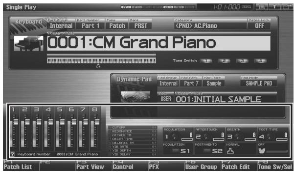
text_image
Single Play Keyboard Part Group Part Number Type Back Category Cancel Lock Internal Part 1 Patch PRST (PND) AC.Piano OFF 0001:CM Grand Piano Tone Switch Dynamic Pad Paol Groud Paol Part Pack Type Pash Mode Internal Part 7 Sample SAMPLE PAD USER 001:INITIAL SAMPLE 1 2 3 4 5 6 7 8 12345678 Keyboard Number 0001:CM Grand Piano CONTIFF RESURANCE ATTICK TH BEET TRUE BELRASE TH VIB RATE VIB DEATH VIB DELAY MODULATION APTESTOUCH SREETH FOOT TYPE 1 2 3 4 5 6 7 8 MODULATION FORTHEMINTO NORMAL OFF S1 S2 Patch List Part View Control PFX User Group Patch Edit Tone Sw/Sel2. While playing the keyboard to produce sound, operate the knobs, sliders or [S1] [S2] buttons.
The sound will change according to the function assigned to each knob, slider or button.
Changing Realtime Controller Settings
Knob 1-4 Settings
-
Hold down [SHIFT] and rotate one of the knobs.
The Knob screen appears. -
Move the cursor to the parameter that you want to set, and turn the VALUE dial or press [INC] [DEC] to set it.
-
If you want to save your settings, press [F7 (Sys Write)]. Press [Exit] to return to the previous screen.
TIP
Realtime controller settings are saved independently for each live set as part of the live settings. This lets you create live sets that make effective use of controller settings. Similarly in studio mode, this setting is saved as part of the studio set.
Knob 1-4 Assign
Specify the functions that will be controlled by the knobs.
Value
OFF: Off
CC01-31, CC32(OFF), 33-95:
Control Change
AFTERTOUCH: Aftertouch
PITCH BEND: Pitch Bend
ARPEGGIO ACCENT: Arpeggio accent rate
ARPEGGIO SHUFFLE: Arpeggio shuffle rate
ARPEGGIO OCT UP: The range in which the arpeggio is sounded will rise in steps of an octave.
ARPEGGIO OCT DOWN: The range in which the arpeggio is sounded will lower in steps of an octave.
MASTER LEVEL: Master Level (p. 297)
DIGITAL/USB INPUT LEVEL:
Digital/USB Input Level (p. 258)
* If the system setting “Knob Assign Source” (p. 293) is set to “System,” the system settings will be used. If it is set to “TEMP,” the settings of the live set or studio set will be used.
Slider 1-8 Settings
-
Hold down [SHIFT] and move one of the sliders.
The Slider screen appears. -
Move the cursor to the parameter that you want to set, and turn the VALUE dial or press [INC] [DEC] to set it.
-
If you want to save your settings, press [F7 (Sys Write)]. Press [Exit] to return to the previous screen.
TIP
Realtime controller settings are saved independently for each live set as part of the live settings. This lets you create live sets that make effective use of controller settings. Similarly in studio mode, this setting is saved as part of the studio set.
Slider 1-8 Assign
Specify the functions that will be controlled by the sliders.
Value
OFF: Off
CC01-31, CC32(OFF), 33-95:
Control Change
AFTERTOUCH: Aftertouch
PITCH BEND: Pitch Bend
ARPEGGIO ACCENT: Arpeggio accent rate
ARPEGGIO SHUFFLE: Arpeggio shuffle rate
ARPEGGIO OCT UP: The range in which the arpeggio is sounded will rise in steps of an octave.
ARPEGGIO OCT DOWN: The range in which the arpeggio is sounded will lower in steps of an octave.
* If the system setting “Slider Assign Source” (p. 293) is set to “System,” the system settings will be used. If it is set to “TEMP,” the settings of the live set or studio set will be used.
S1/S2 Switch Settings
- Hold down [SHIFT] and press [S1] [S2].
The Switch screen appears.
-
Move the cursor to the parameter that you want to set, and turn the VALUE dial or press [INC] [DEC] to make the setting.
-
If you want to save your settings, press [F7 (Sys Write)]. Press [Exit] to return to the previous screen.
TIP
Realtime controller settings are saved independently for each live set as part of the live settings. This lets you create live sets that make effective use of controller settings. Similarly in studio mode, this setting is saved as part of the studio set.
Switch S1/S2 Assign
Specify the functions that will be controlled by the [S1] [S2] switches.
Value
OFF, CC01 - CC31, CC32 (OFF), CC33 - CC95, AFTERTOUCH, MONO/POLY, PFX SWITCH, MFX SWITCH, RESERVE, CHORUS SWITCH, REVERB SWITCH, MASTERING SWITCH, MASTER KEY UP, MASTER KEY DOWN, SCALE TUNE SWITCH
Switch 1/2 Assign Mode
Specify the functions that will be controlled by the [S1] [S2] switches.
Value
LATCH: The on/off status will alternate each time you press [S1] [S2].
MOMENTARY: The status will be on only while you hold down [S1] [S2].
TIP
If Single mode is selected, assignable switches are available when the keyboard part is selected.
Using a Pedal to Modify the Sound (Control Pedal)
You can modify the sound by pressing a pedal that is connected to the rear panel PEDAL CONTROL 1, 2 jacks.
Pedal such as expression pedals (DP-8; available separately), pedal switches (DP series; available separately), or foot switches (BOSS FS-U; available separately) can be connected to the Fantom-G.
- Access the Single Play screen (p. 46).
- While playing the keyboard to produce sound, operate a pedal.
The sound will change according to the function that is assigned to the control pedal.
Making Control Pedal Settings
- Press [MENU].
- Turn the VALUE dial or use [CURSOR] to select "System," and then press [ENTER].
The System Setup screen appears.
- Press [F1 (Up)] or [F2 (Down)] to select "Pedal/D Beam."
- Turn the VALUE dial or press [INC] [DEC] to make the setting.
- If you want to save your settings, press [F7 (Sys Write)]. Press [Exit] to return to the Single Play screen.
cf.
See “Pedal/D Beam” (p. 291) for each parameter's functions.
About Arpeggio
The Fantom-G's Arpeggio function lets you produce arpeggios automatically; simply hold down some keys, and a corresponding arpeggio will be played automatically.
Playing Arpeggios
MEMO
Use “Arpeggio Part Number” (p. 146) to specify the parts that will use the Arpeggio function. The Chord Memory function (p. 81) will also apply to the parts selected by the Arpeggio Part setting.
MEMO
If you want to play arpeggios in Live mode or Studio mode, you'll also need to check the “Arpeggio” (p. 146) parameter of the live set or studio set.
MEMO
In Live mode or Studio mode, if the keyboard switch is turned off for all part groups, the current part will be the arpeggio part.
Turning Arpeggio On and Off
- Press [ARPEGGIO] to turn it on.
The button will light.
- Play a chord on the keyboard.
The Fantom-G will play an arpeggio, according to the notes forming the chord you have just voiced.
- To finish playing arpeggios, press [ARPEGGIO] again to turn it off.
cf.
For details regarding each parameter, refer to “Arpeggio Settings” (p. 78).
Using in Combination with the Chord Memory Function
When performing with the Arpeggio, you can also use it along with the Chord Memory function (p. 81). After first storing complex Chord Forms in memory, you can then call them up when Arpeggio function is on, and you can easily play complex arpeggio sounds just by pressing a single key.
Determining the Tempo for Arpeggio Performances
The current tempo value appears in the display.
- Press VALUE dial or [INC], [DEC] to set the tempo value (5.00–300.00), or set the value by tapping [F6 (Tap Tempo)] a number of times with the same rhythm (Tap Tempo). By holding down [SHIFT] and turning the VALUE dial you can adjust the value below the decimal point.
* If you press [F7 (Click)] to turn on, the click will sound.
- When you have made the setting, press [F8 (Close)].
Holding an Arpeggio
By using the following procedure, you can produce arpeggios even without continuing to press the keyboard.
- Press [HOLD].
The indicator will light.
-
Play a chord on the keyboard.
-
If you play a different chord or notes while the arpeggio is being held, the arpeggio will change accordingly.
-
To cancel Arpeggio Hold, press [HOLD] once again.
When Using a Hold Pedal
If you play an arpeggio while pressing the hold pedal, the arpeggio will continue to be played even if you release the chord.
-
Connect an optional pedal switch (DP series etc.) to the HOLD PEDAL jack.
-
Press [ARPEGGIO] to turn on the arpeggio.
-
Play a chord while pressing the hold pedal.
-
If you play a different chord or notes while the arpeggio is being held, the arpeggio will change accordingly.
Arpeggio Settings
-
Hold down [SHIFT] and press [ARPEGGIO].
-
Press [CURSOR] to move the cursor to each parameter, and either turn the VALUE dial or press [INC] or [DEC] to make the setting.
-
When you have made the setting, press [EXIT].
Style (Arpeggio Style)
Specifies the basic way in which the arpeggio will be played.
cf.
You can create your own original Arpeggio Style by importing SMF or phrase data into an arpeggio user style. For details, refer to “Importing SMF or Phrases to an Arpeggio Style” (p. 79).
Variation (Arpeggio Variation)
The arpeggiator provides several variations (performance patterns) for each arpeggio style. This parameter selects the variation number. The number of variations will differ according to the arpeggio style.
Motif (Arpeggio Motif)
Sets the order in which notes of the chord will sound.
Value
| UP: | Notes you press will be sounded, beginning from low to high. |
| DOWN: | Notes you press will be sounded, from high to low. |
| UP&DOWN: | Notes you press will be sounded, from low to high, and then back down from high to low. |
| RANDOM: | Notes you press will be sounded, in random order. |
| NOTE ORDER: | Notes you press will be sounded in the order in which you pressed them. By pressing the notes in the appropriate order you can produce melody lines. Up to 128 notes will be remembered. |
| GLISSANDO: | Each chromatic step between the highest and lowest notes you press will sound in succession, repeating upward and downward. Press only the lowest and the highest notes. |
| CHORD: | All notes you press will sound simultaneously. |
| AUTO1: | The timing at which keys will sound will be assigned automatically, giving priority to the lowest key that was pressed. |
| AUTO2: | The timing at which keys will sound will be assigned automatically, giving priority to the highest key that was pressed. |
| PHRASE: | Pressing a single key will sound the phrase based on the pitch of that key. If multiple keys are pressed, the last-pressed key will be valid. |
Accent Rate (Arpeggio Accent Rate)
Modifies the strength of accents and the length of the notes to adjust the “groove” feel of the arpeggio. A setting of “100%” will produce the most pronounced groove feel.
Value: 0–100%
Shuffle Rate (Arpeggio Shuffle Rate)
This setting lets you modify the note timing to create shuffle rhythms.
With a setting of “50%” the notes will be spaced evenly. As the value is increased, the note timing will have more of a “dotted” (shuffle) feel.
Value: 0–100%
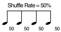
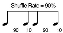
Shuffle Resolution (Arpeggio Shuffle Resolution)
Specify the timing resolution in terms of a note value. The note value can be specified as either an 16th note or a eighth note.
Value: ♪, ♪
Keyboard Velocity (Arpeggio Keyboard Velocity)
Specifies the loudness of the notes that you play.
If you want the velocity value of each note to depend on how strongly you play the keyboard, set this parameter to "REAL." If you want each note to have a fixed velocity regardless of how strongly you play the keyboard, set this parameter to the desired value (1–127).
Value: REAL, 1–127
Octave Range (Arpeggio Octave Range)
Sets the key range in octaves over which arpeggio will take place. If you want the arpeggio to sound using only the notes that you actually play, set this parameter to "0." To have the arpeggio sound using the notes you play and notes 1 octave higher, set this parameter to "+1." A setting of "-1" will make the arpeggio sound using the notes you play and notes 1 octave lower.
Value: -3- +3
Key Trigger (Arpeggio Key Trigger)
Turn this “ON” if you want the arpeggio to start at the moment that you press the key. If you want the arpeggio to start playing in synchronization with the sequencer, turn this “OFF.”
Value: OFF, ON
Importing SMF or Phrases to an Arpeggio Style
You can create your own original Arpeggio Style by importing SMF or phrase data into an arpeggio user style.
MEMO
If you want to import SMF data, you must first copy the Standard MIDI File (SMF) from your computer to the Fantom-G as described in “Copying a Standard MIDI File (SMF) from Your Computer to the Fantom-G” (p. 212).
- Hold down [SHIFT] and press [ARPEGGIO].
- Press [F1 (Import Style)].
- Press [F2 (SMF List)] or [F3 (Phrase List)] to switch the list from which you want to import.
- Turn the VALUE dial to select the SMF or phrase that you want to import.
MEMO
By pressing [F7 (Preview)] you can audition the selected SMF or phrase.
MEMO
If you decide not to import, press [F8 (Exit)].
-
Press [F6 (Import)].
-
Assign a name to the Arpeggio Style that you want to import. After you've assigned a name, press [F8 (OK)].
cf.
For details on how to enter a name, refer to “Assigning a Name” (p. 42).
-
Select the desired Import Destination. Turn the VALUE dial to make your choice, and then press the [F8 (Write)] button. A confirmation message will appear.
-
Press [F7 (OK)] to execute.
The SMF or phrase will be imported into the arpeggio user style.
MEMO
Please note the following points regarding importing an arpeggio.
- Only SMF Format 0 is supported. If the data is incorrect, the screen will indicate “Cannot Import SMF Format 1!” or “Illegal File!”.
- Only the note data will be imported from the original data into the arpeggio.
- Up to 500 events (with a note on/off counting as one event) can be imported. If there are more than 500 events, the screen will indicate “Too Many Data!”.
Saving the Arpeggio You Have Created (Write)
The Arpeggios you create are temporary; they are deleted as soon as you turn off the power or select some other Arpeggio. You can store 128 arpeggios in the User memory.
- Confirm that the current Arpeggio is the one you want to save.
- Press [F7 (Write)].
The Arpeggio name entry screen will appear (p. 42). - When you have finished entering the name, press [F8 (OK)]. A screen in which you can select the destination for the write will appear.
- Turn the VALUE dial or use [INC] [DEC] to select the write destination.
- Press [F8 (Write)].
A message will ask you for confirmation. - To write the data, press [F7 (OK)].
Never switch off the Fantom-G while data is being saved. To cancel, press [F8 (EXIT)].
About the Chord Memory Function
Chord Memory is a function that allows you to play chords based on pre-programmed Chord Forms, just by pressing a single key on the keyboard. The Fantom-G can store 128 user chord forms.
NOTE
When you use the Chord Memory function with a tone for which the Mono/Poly Parameters (p. 105) is Mono, only one sound in the chord is played. When using the Chord Memory function to turn Poly the Mono/Poly Parameters.
Using in Combination with the Arpeggio Function
When performing with the Chord Form function, you can also use it along with the Arpeggio function (p. 78). After first storing complex Chord Forms in memory, you can then call them up when Arpeggio is on, and you can easily create complex arpeggio sounds just by pressing a single key.
Performing with the Chord Memory Function
MEMO
Use “Arpeggio Part Number” (p. 146) to specify the parts that will use the Chord Memory function. The Arpeggio function (p. 78) will also apply to the pats selected by the Arpeggio Part setting.
Turning Chord Memory Function On and Off
- Press [CHORD MEMORY] to turn it on.
The button will light. - Play the keyboard.
A chord will sound according to the currently selected chord form.
When you press the C4 key (Middle C), the chord is played using the exact chord structure recorded in the Chord Form. This is referenced to the C4 key; parallel chords are played by pressing other keys. - To finish the chord Memory Function, press [CHORD MEMORY] again to turn it off.
MEMO
Selecting Chord Forms
Changing the chord form will change the notes in the chord.
- Hold down [SHIFT] and press [CHORD MEMORY].
The following screen appears.
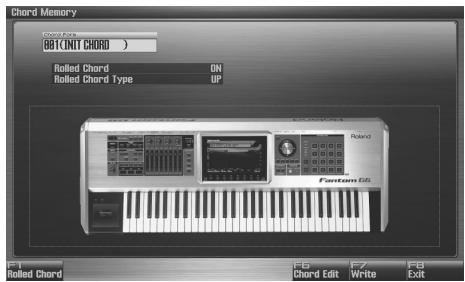
text_image
Chord Memory ON BAT/CNIT CHORD ) Rolled Chord On Rolled Chord Type UP Rotand F6 Chord Edit F7 Write F8 Exit Rolled Chord F1 Rolled Chord- Either turn the VALUE dial or use [INC] [DEC] to select a Chord Form number.
The notes of the chord will be displayed.
- When you have finished selecting a Chord Form, press [Exit].
Sounding a Chord in the Order of Its Notes (Rolled Chord)
This causes the notes within a chord to be sounded consecutively, rather than simultaneously. Since the playback speed will change according to the force with which you play the keyboard, you can vary your playing dynamics to create a realistic simulation of playing a guitar.
- Hold down [SHIFT] and press [CHORD MEMORY]. The Chord Memory screen appears.
- Press [F1 (Rolled Chord)] to turn on. With this setting, the notes of the chord will be sounded consecutively when you play the keyboard.
Changing the order in which notes are sounded (Rolled Chord Type)
You can change the order in which the notes of a chord are sounded.
- Hold down [SHIFT] and press [CHORD MEMORY]. The Chord Memory screen appears.
- Use ▲ or ▼ to select "Rolled Chord Type."
- Either turn the VALUE dial or use [INC] [DEC] to change a value.
Value
UP: Notes will be sounded in order from bottom to top.
DOWN: Notes will be sounded in order from top to bottom.
ALTERNATE: The order in which the notes are sounded will change each time you play the keyboard.
L-DOWN: The lowest note will be sounded first, and then notes will be sounded in order from the top down.
* If you press C E G B, the notes will be sounded as C B G E.
U-UP: The highest note will be sounded first, and then notes will be sounded in order from the bottom up.
* If you press C E G B, the notes will be sounded as B C E G.
Creating Your Own Chord Forms
Not only can you use the prepared internal Chord Forms, which determine the constituent notes of chords played using the Chord Memory function, but you can also freely create and rewrite them as well.
- Hold down [SHIFT] and press [CHORD MEMORY].
- Turn the VALUE dial to select a chord form.
- Press [F6 (Chord Edit)].
The Chord Form Edit screen appears.
- Use the keyboard to input the chord that you want to play. When you press a key, the note will be added in the screen. If you input a note by mistake, press [F5 (Del Note)]. You can also erase a note you input by pressing the same key. You can press [F6 (Preview)] to hear the chord that you are inputting.
- If you want to save the chord form you created, proceed to step 3 of "Saving the Chord Forms You Have Created" (p. 82). If you don't want to save it, press [F8 (Exit)].
Saving the Chord Forms You Have Created
The Chord Form you create are temporary; they are deleted as soon as you turn off the power or select some other Style. If you want to keep a Chord Form you have made, save it to the Fantom-G's user memory.
- Hold down [SHIFT] and press [CHORD MEMORY].
Confirm that the chord form is selected that you want to save.
- Press [F7 (Write)].
The Chord Form name entry screen will appear (p. 42).
-
When you have finished entering the name, press [F8 (OK)]. A screen will appear, allowing you to select the write destination.
-
Use ▲ or ▼ to select the write destination.
-
Press [F8 (Write)].
A message will ask you confirm.
- To save the chord form, press [F7 (OK)].
Never switch off the Fantom-G while data is being saved.
* To cancel, press [F8 (EXIT)].
04: Sound Generator, Section 3 (Creating Sounds)
This chapter explains how to create sounds such as patches, live sets, and effects.
- Patch....p. 84
• Rhythm Set.... p. 112
• Sample Set...... p. 126
• Live Set/Studio Set...... p. 132 - Adding Effects ...... p. 150
• Effects List ...... p. 161
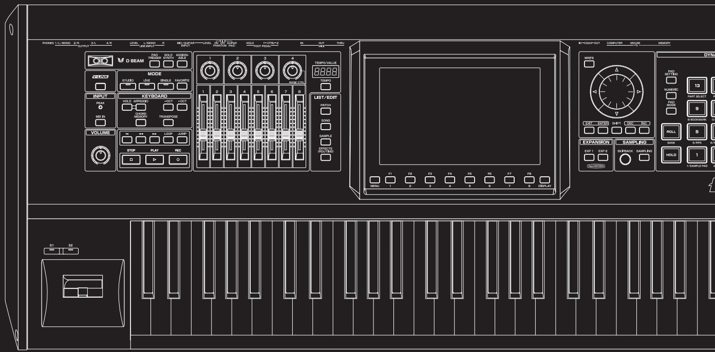
text_image
PROKES L/L MISO 2/R OUTPUT 3/L 4/R LEVEL L-MISO 5 MECUTAIN LEVEL CTM GURAN HOLD I-CTR=2 IN OUT TURI D BEAM RAD TRIGGER SWORD ASSEMB- MODE STUDIO live single fancine INPUT PEAK HOLD APPROXIO 3OCT 4OCT CHORD MEOCON TRANSPOSE VOLUME 1 2 3 4 TEMPO VALUE 1 2 3 4 5 6 7 8 TEMP LIST/EDIT PATCH DOYS SAMPLE CAPSIC (RDT/RDS) EXPANSION SAMPLING EXP 1 EXP 2 SREBACK SAMPLING HOLD 1 SAMPLE RAD 2 S1 SB MIN: 1 2 3 4 5 6 7 8 DISPLAYWith the Fantom-G, you have total control over a wide variety of settings. Each item that can be set is known as a parameter. When you change the values of parameters, you are doing what is referred to as Editing. This chapter explains the procedures used in creating patches, and the functions of the patch parameters.
How to Make Patch Settings
Start with an existing patch and edit it to create a new patch. Since a patch is a combination of up to any four tones, you should listen to how the individual tones sound before you edit.
Four Tips for Editing Patches
- Select a patch that is similar to the sound you wish to create (p. 47).
It's hard to create a new sound that's exactly what you want if you just select a patch and modify its parameters at random. It makes sense to start with a patch whose sound is related to what you have in mind.
● Decide which tones will sound (p. 50).
When creating a patch, it is important to decide which tones you are going to use. In the Patch Pro Edit screen, set Tone Switch 1–4 to specify whether each tone will sound (on), or not (off). It is also important to turn off unused tones to avoid wasting voices, unnecessarily reducing the number of simultaneous notes you can play.
● Check the Structure setting (p. 92).
The important Structure parameter determines how the four tones combine. Before you select new tones, make sure you understand how the currently selected tones are affecting each other.
● Turn Effects off (p. 150).
Since the Fantom-G effects have such a profound impact on its sounds, turn them off to listen to the sound itself so you can better evaluate the changes you're making. Since you will hear the original sound of the patch itself when the effects are turned off, the results of your modifications will be easier to hear. Actually, sometimes just changing effects settings can give you the sound you want.
Editing a Patch Quickly (Patch Zoom Edit)
The Patch Zoom Edit screen allows you to edit the most important parameters of a patch. If you want to have access to all of the parameters, use the Patch Pro Edit screen (p. 86).
-
Select the patch whose settings you want to edit (p. 47).
-
Press [PATCH].
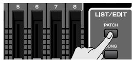
The Patch Zoom Edit screen appears.

text_image
Groups Parameters Patch Zoom Hit PITCH Env TVF TVF Env TVA Env Structure LFD 1 LFD 2 Step LFD PITCH Current Tone Tone I Tone Switch PITCH ENV ADXR Tone/Layer A D S R T1 T2 T3 T4 40 80 40 0 L8 L1 L2 L3 L4 0 -30 +30 0 0 Group/Up Group/Down F4 F5 F6 F7 F8 Util Menu PFX Pro Edit Part Select Tone Sw/SelF-key operations in the Patch Zoom Edit screen
| F-key | Explanation | Page | |
| F1 Group/Up | Moves the edit group tab upward. | - | |
| F2 Group/Down | Moves the edit group tab downward. | - | |
| F4 Util Menu | Patch Initialize | Initializes the settings of the currently selected patch. | p. 87 |
| Tone Initialize | Initializes the settings of the currently selected tone. | p. 87 | |
| Tone Copy | Copies tone settings from a patch to the specified tone of the currently selected patch. | p. 87 | |
| F5 PFX | Accesses the PFX (Patch Multi-effect) editing screen. | p. 157 | |
| F6 Pro Edit | Accesses the Patch Pro Edit screen, where you can edit all of the parameters. | p. 86 | |
| F7 Part Select | Selects the part to be edited. | - | |
| F8 Tone Sw/Sel | Selects the tones that will sound. | p. 85 | |
- The parameters are organized into several editing groups. Press [F1 (Up)] or [F2 (Down)] to select the tab for the editing group that contains the parameter you wish to edit.
cf.
For details on each parameter, refer to the following pages.
| Parameter name | Page | Parameter name | Page |
| Pitch Envelope | p. 97 | Structure Type | p. 92 |
| TVF | p. 98 | LFO1/2 | p. 103 |
| TVF Envelope | p. 100 | Step LFO | p. 104 |
| TVA Envelope | p. 101 |
• To change the part that you want to edit
Press [F7 (Part Select)].
-
Press [CURSOR] button to move the cursor to the parameter you wish to modify.
-
Press [F8 (Tone Sw/Sel)] to select the tone that you want to edit.
The Tone Switch/Select window appears.

text_image
Tone Switch/Select (Full) 2 3 4 5 6 7 8 (Push [EXIT] to close) F1 F2 F3 F4 F5 F6 F7 F8 Sw 1 Sw 2 Sw 3 Sw 4 Select 1 Select 2 Select 3 Select 4Press any one of the [F5 (Select 1)]–[F8 (Select 4)] buttons to select the tone that you want to edit.
- Simultaneously editing the same parameter of multiple tones
To select the tones you want to edit at the same time, simultaneously press two or more of the [F5 (Select 1)]-[F8 (Select 4)] buttons, making them light.
• To switch a tone on/off
Press a [F1 (Sw 1)]–[F4 (Sw 4)] button to switch the corresponding tone on/off.
TIP
You can also use the pads to select tones and switch them on/off. → “7 TONE SEL/SW (Using the Pads to Select Tones or Switch Them On/Off)” (p. 197)
-
When you have made your selection, press [EXIT].
-
Turn the VALUE dial or press [INC] [DEC] to get the value you want.
If you've selected two or more tones, your editing will modify the parameter values for all selected tones by the same amount.
-
Repeat steps 3–7 to set each parameter you want to edit.
-
If you wish to save the changes you've made, press [WRITE] to perform the Save operation (p. 88). If you do not wish to save changes, press [EXIT].
If you return to the Single Play screen without saving, the "√" symbol will be displayed at the right of the patch name, indicating that the patch settings have been edited.
NOTE
The settings you edit are temporary, and will be lost if you turn off the power, switch the sound generator mode, or select a different sound.
Editing All Parameters of a Patch (Patch Pro Edit)
The Patch Pro Edit screen allows you to edit all parameters of a patch.
1. Select the patch whose settings you want to edit (p. 47).

If you want to create a patch from scratch (rather than starting from an existing patch), execute the Initialize operation (p. 87).
2. Press [PATCH] twice.
![ROLAND FANTOM G8 - Press [PATCH] twice. - 1](/content/2025/01/130804/images/1e3b8682480ca9b1a83d97c1adf9d15901dcdad5241e562c0964c3aaac5a44b2.jpg)
The Patch Pro Edit screen appears.
![ROLAND FANTOM G8 - Press [PATCH] twice. - 2](/content/2025/01/130804/images/92bd88f80ea5725dd06759f3f3481748f5ef7a35dcc1eefc44e453ba5734a22c.jpg)
text_image
Groups Parameters Patch Pro Ekt Patch Part 1 Part 2 Patch Name [ CM Grand Piano ] Patch Category (CN0) AC Piano Patch Level 127 Patch Pan 0 Patch Priority LOUDEST Octave Shift 0 Patch Coarse Tune 0 Patch Fine Tune 0 Stretch Tune Depth 3 Analog Feel 0 Cutoff Offset 0 Resonance Offset 0 Attack Time Offset 0 Release Time Offset 0 Velocity Sens Offset 0 F1 Group/Up Group/Down F4 F5 F6 F7 F8 Opti Menu PFX Zoom Edit Part Select Tone Sw/SelF-key operations in the Patch Pro Edit screen
| F-key | Explanation | Page | |
| F1 Group/Up | Moves the edit group tab upward. | - | |
| F2 Group/Down | Moves the edit group tab downward. | - | |
| F3 Set Stereo | This is shown if you're editing the WAVE group. It recalls the right wave (R) from the left wave (L) of a stereo wave. | p. 91 | |
| F4 Util Menu | Patch Initialize | Initializes the settings of the currently selected patch. | p. 87 |
| Tone Initialize | Initializes the settings of the currently selected tone. | p. 87 | |
| Tone Copy | Copies tone settings from a patch to the specified tone of the currently selected patch. | p. 87 | |
| F5 PFX | Accesses the PFX (Patch Multi-effect) editing screen. | p. 157 | |
| F6 Zoom Edit | Accesses the Zoom Edit screen, where you can edit the most important parameters. | p. 84 | |
| F7 Part Select | Selects the part to be edited. | - | |
| F8 Tone Sw/Sel | Selects the tones that will sound. | p. 85 | |
- The parameters are organized into several editing groups. Press [F1 (Up)] or [F2 (Down)] to select the tab for the editing group that contains the parameter you wish to edit.
![ROLAND FANTOM G8 - Press [PATCH] twice. - 3](/content/2025/01/130804/images/7a8b9f702900edc36a7cb2698f50e0bc3db9f94e921b76bf95b4416c28675ddb.jpg)
See “Functions of Patch Parameters” (p. 89) for each parameter’s functions.
- To change the part that you want to edit Press [F7 (Part Select)].
-
Press [CURSOR] button to move the cursor to the parameter you wish to modify.
-
Press [F8 (Tone Sw/Sel)] to select the tone that you want to edit. The Tone Switch/Select window appears.
![ROLAND FANTOM G8 - Press [PATCH] twice. - 4](/content/2025/01/130804/images/f551f442cbd042312fa4c4733cb4b47f7119279d1d839b1e5d29701ab65149b9.jpg)
text_image
Tone Switch/Select (F1 Sw 1) F2 Sw 2) F3 Sw 3) F4 Sw 4) (F5 Select 1) F6 Select 2) F7 Select 3) F8 Select 4) (Push (EXIT) to close)Press any one of the [F5 (Select 1)]–[F8 (Select 4)] buttons to select the tone that you want to edit.
- Simultaneously editing the same parameter of multiple tones
To select the tones you want to edit at the same time, simultaneously press two or more of the [F5 (Select 1)]-[F8 (Select 4)] buttons, making them light.
• To switch a tone on/off
Press a [F1 (Sw 1)]–[F4 (Sw 4)] button to switch the corresponding tone on/off.
![ROLAND FANTOM G8 - Press [PATCH] twice. - 5](/content/2025/01/130804/images/a1b2d78dd5767ac0ede3bebbddfe906d40d5bee8cc72c3cea162f401d7c243f6.jpg)
You can also use the pads to select tones and switch them on/off. → “7 TONE SEL/SW (Using the Pads to Select Tones or Switch Them On/Off)” (p. 197)
-
When you have made your selection, press [EXIT].
-
Turn the VALUE dial or press [INC] [DEC] to get the value you want.
If you've selected two or more tones, your editing will modify the parameter values for all selected tones by the same amount.
-
Repeat steps 3–7 to set each parameter you want to edit.
-
If you wish to save the changes you've made, press [WRITE] to perform the Save operation (p. 88). If you do not wish to save changes, press [EXIT] to return to the Single Play screen.
If you return to the Single Play screen without saving, the “√” symbol will be displayed at the right of the patch name, indicating that the patch settings have been edited.
![ROLAND FANTOM G8 - Press [PATCH] twice. - 6](/content/2025/01/130804/images/d859e904fec61552bc00a7e01e8e933f99e2a1501c014c52533ee72abbe2490c.jpg)
The settings you edit are temporary, and will be lost if you turn off the power, switch the sound generator mode, or select a different sound.
Initializing Patch/Tone Settings (Patch Initialize/Tone Initialize)
"Initialize" means to return the settings of the currently selected sound to a standard set of values.
Patch Initialize will initialize the settings of the currently selected patch.
Tone Initialize will initialize the settings of the currently selected tone.
NOTE
The Initialize operation will affect only the currently selected sound; the sounds that are stored in user memory will not be affected. If you wish to restore all of the Fantom-G's settings to their factory values, perform a Factory Reset (p. 284).
-
Select the patch that you want to initialize (p. 47).
-
Press [PATCH].
- Press [F4 (Util Menu)].
The Patch Utility Menu window appears.
- Press ▲ or ▼ to choose what you want to initialize (Patch Initialize or Tone Initialize), and then press [F8 (Select)].
If you decide to cancel the operation, press [F7 (Cancel)].
A message will ask you for confirmation.
- Press [F7 (OK)] to execute.
To cancel, press [F8 (EXIT)].
Copying Patch (Tone) Settings (Patch Tone Copy)
This operation copies the settings of any desired patch to the currently selected patch. You can use this feature to make the editing process faster and easier.
- Select that you want to edit and the copy-destination patch (p. 47).
- Press [PATCH].
- Press [F4 (Util Menu)].
The Patch Utility Menu window appears.
- Press ▲ or ▼ to choose "Patch Tone Copy," and then press [F8 (Select)].
If you decide to cancel the operation, press [F7 (Cancel)].
The Patch Tone Copy window appears.
- Press [CURSOR] to move the cursor, select the "Source (copy-source)" bank and number, and patch tone.
- Turn the VALUE dial or use [INC] [DEC] to make settings.
- Press [CURSOR] to move the cursor, select the "Destination (copy-destination)" patch tone number.
- Turn the VALUE dial or use [INC] [DEC] to make settings.
- Press [F8 (Execute)].
A message will ask you for confirmation.
- Press [F7 (OK)] to return to execute.
To cancel, press [F8 (EXIT)].
The Compare Function
For the Patch Tone Copy operations, you can use the Compare function.
The Compare function allows you to hear the copy-source patch in order to verify it.
If you want to play the copy-source patch, press [F6 (Compare)].
NOTE
The patch auditioned using the Compare function may sound slightly different than when it is played normally.
Cautions When Selecting a Waveform
The sounds of the Fantom-G are based on complex PCM waveforms, and if you attempt to make settings that are contrary to the type of the original waveform, the results will not be as you expect.
The internal waveforms of the Fantom-G fall into the following two banks.
One-shot: These waveforms contain sounds that have short decays. A one-shot waveform records the initial rise and fall of the sound. Some of the Fantom-G's one-shot waveforms are sounds that are complete in themselves, such as percussive instrument sounds. The Fantom-G also contains many other one-shot waveforms that are elements of other sounds. These include attack components such as piano-hammer sounds and guitar fret noises.
Looped: These waveforms include sounds with long decays as well as sustained sounds. Loop waveforms repeatedly play back (loop) the portion of the waveform after the sound has reached a relatively steady state. The Fantom-G's looped waveforms also include components of other sounds, such as piano-string resonant vibrations and the hollow sounds of brass instruments.
The following diagram shows an example of sound (electric organ) that combines one-shot and looped waveforms.
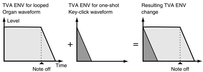
text_image
TVA ENV for looped Organ waveform Level + Time Note off TVA ENV for one-shot Key-click waveform Resulting TVA ENV change Note offCautions When Using a One-shot Waveform
It is not possible to use the envelope to modify a one-shot waveform to create a decay that is longer than the original waveform, or to turn it into a sustaining sound. If you were to program such an envelope, you would be attempting to shape a portion of the sound that simply doesn't exist, and the envelope would have no effect.
Cautions When Using a Loop Waveform
With many acoustic instruments such as piano and sax, extreme timbral changes occur during the first few moments of each note. This initial attack is what defines much of the instrument's character. For such waveforms, it is best to use the complex tonal changes of the attack portion of the waveform just as they are, and to use the envelope only to modify the decay portion. If you attempt to use the envelope to modify the attack portion as well, the characteristics of the original waveform may prevent you from getting the sound that you intend.
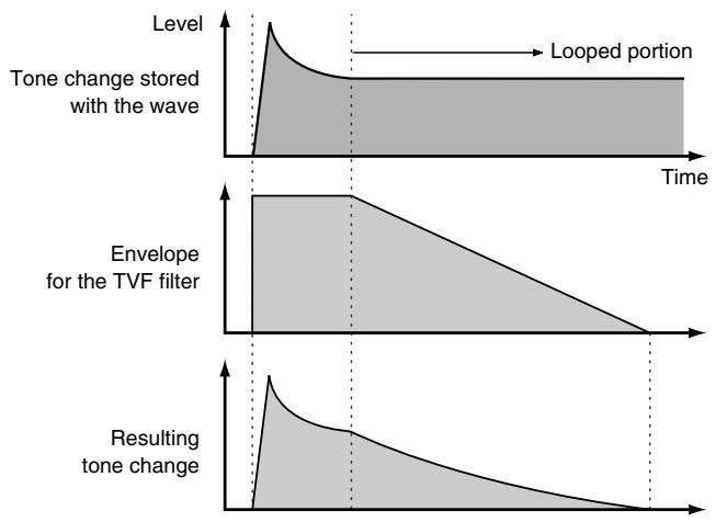
line
| Time Segment | Tone Change Stained with Wave | Envelope for the TVF filter | Resulting Tone Change | | ------------ | ----------------------------- | --------------------------- | --------------------- | | Top Left | Peak | - | - | | Middle Right | - | - | - | | Bottom Right | - | - | - |Saving Patches You've Created (Write)
Edits you make to the settings are temporary, and will be lost if you turn off the power, switch the sound generator mode, or select a different sound. If you want to keep the modified sound, you must save it in the USER bank.
When you edit the patch settings, the “√” symbol will appear in the Single Play screen. When you save the patch, the “√” symbol will disappear.
NOTE
When you perform the save procedure, the data that previously occupied the save destination will be lost.
- Make sure that the patch you wish to save is selected.
- Press [WRITE].
The WRITE MENU window appears.
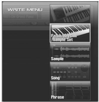
text_image
WRITE MENU RGB1-CM Grand Piano Tone Switch Patch/Phrytirm /Sample Set Sample Song Phrase- Select "Patch / Rhythm / Sample Set."
Press ▲ or ▼ to select "Patch / Rhythm / Sample Set," and then press [F8 (Select)].
The Patch Name window appears.
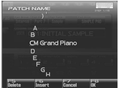
text_image
PATCH NAME PAD Group Pad Part Pad Type Pad Node Internal Part 7 Sample SAMPLE PAD A USER NOT 1:INITIAL SAMPLE CM Grand Piano D E F G H MODULATE RFTERTOUCH BRETTH FOOT TYPE 1 2 3 4 5 MODULATION DOCUMENTO NORMAL OFF F5 F6 F7 F8 Delete Insert Cancel OK- Assign a name to the patch.
cf.
For details on assigning names, refer to “Assigning a Name” (p. 42)
- When you have finished inputting the name, press [F8 (OK)].
A screen will appear, allowing you to select the write-destination patch.
- Turn the VALUE dial or use [INC] [DEC] to select the patch number.
TIP
By pressing [F6 (Compare)] you can check the save-destination patch (Compare function).
- Press [F8 (Write)].
A message will ask you for confirmation.
NOTE
Never switch off the Fantom-G while data is being saved.
- Press [F7 (OK)] to execute the save operation.
To cancel the operation, press [F8 (EXIT)].
Auditioning the Save-Destination Patch (Compare)
Before you save a patch, you can audition the patch which currently occupies the save destination to make sure that it is one you don't mind overwriting. This can help prevent important patches from being accidentally overwritten and lost.
-
Follow the procedure in "Saving Patches You've Created (Write)" through step 6 to select the save destination.
-
Press [F6 (Compare)] to turn on.
-
Play the keyboard or pad to sound the save destination patch, then check whether you really want to overwrite it.
NOTE
The patch auditioned using the Compare function may sound slightly different than when it is played normally.
-
If you wish to change the save destination, re-specify the save-destination patch by turning the VALUE dial.
-
Press [F8 (Write)].
A message will ask you for confirmation.
- Press [F7 (OK)] once again to execute the Save operation.
Functions of Patch Parameters
This section explains the functions the different patch parameters have, as well as the composition of these parameters.
MEMO
Parameters marked with a “★” can be controlled using specified MIDI messages (Matrix Control). Settings in Matrix Ctrl screen will determine how these parameters are controlled (p. 109).
If a number is displayed for the parameter name, (1, 2, 3, 4), you can use the realtime controller knob of the corresponding number (the left most knob is number 1, the right most knob is number 4) to set the value.
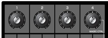
text_image
1 2 3 4 MAGIC CTRLSettings Common to the Entire Patch (General)
Patch Name
Specifies the name of the patch.
By pressing [ENTER], you can assign a name to the patch.
Value: space, A-Z, a-z, 0-9,! " # \$ % & ' ( ) * + ,-. / : ;<=> ? @ [ \ ] ^ _ ` { | }
cf.
For details on entering a name, refer to “Assigning a Name” (p. 42).
Patch Category
Specifies the type (category) of the patch.
It also determines the phrase that will be sounded when using the Phrase Preview function.
cf.
For details on the possible category names, refer to (p. 48).
Patch Level
Specifies the volume of the patch.
Value: 0–127
Patch Pan
Specifies the pan of the patch. "L64" is far left, "0" is center, and "63R" is far right.
Value: L64-0-63R
Patch Priority
This determines how notes will be managed when the maximum polyphony is exceeded (128 voices).
Value
LAST: The last-played voices will be given priority, and currently sounding notes will be turned off in order, beginning with the first-played note.
LOUDEST: The voices with the loudest volume will be given priority, and currently sounding notes will be turned off, beginning with the lowest-volume voice.
Octave Shift
Adjusts the pitch of the patch's sound up or down in units of an octave (+/-3 octaves).
Value: -3- +3
Patch Coarse Tune ★
Adjusts the pitch of the patch's sound up or down in semitone steps (+/-4 octaves).
Value: -48- +48
Patch Fine Tune
Adjusts the pitch of the patch's sound up or down in 1-cent steps (+/ -50 cents).
Value: -50- +50

One cent is 1/100th of a semitone.
Stretch Tune Depth
This setting allows you to apply “stretched tuning” to the patch. (Stretched tuning is a system by which acoustic pianos are normally tuned, causing the lower range to be lower and the higher range to be higher than the mathematical tuning ratios would otherwise dictate.) With a setting of “OFF,” the patch’s tuning will be equal temperament. A setting of “3” will produce the greatest difference in the pitch of the low and high ranges.
Value: OFF, 1–3
The diagram shows the pitch change relative to equal temperament that will occur in the low and high ranges. This setting will have a subtle effect on the way in which chords resonate.
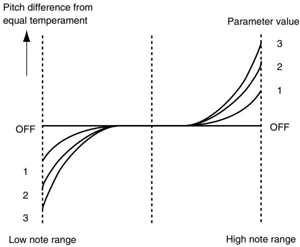
line
| Parameter value | Pitch difference from equal temperament | | --------------- | --------------------------------------- | | 1 | OFF | | 2 | OFF | | 3 | OFF |Analog Feel (Analog Feel Depth)
Specifies the depth of 1/f modulation that is to be applied to the patch. (1/f modulation is a pleasant and naturally-occurring ratio of modulation that occurs in a babbling brook or rustling wind.) By adding this “1/f modulation,” you can simulate the natural instability characteristic of an analog synthesizer.
Value: 0–127
Cutoff Offset
Cutoff Frequency Offset alters the cutoff frequency of the overall patch, while preserving the relative differences between the cutoff frequency values set for each tone in the Cutoff Frequency parameters (p. 98).
Value: -63- +63
NOTE
This value is added to the cutoff frequency value of a tone, so if the cutoff frequency value of any tone is already set to "127" (maximum), positive "+" settings here will not produce any change.
Resonance Offset
Resonance Offset alters the resonance of the overall patch, while preserving the relative differences between the resonance values set for each tone in the Resonance parameter (p. 98).
Range: -63- +63
* Resonance: emphasizes the overtones in the region of the cutoff frequency, adding character to the sound.
NOTE
This value is added to the resonance value of a tone, so if the resonance value of any tone is already set to “127” (maximum), positive “+” settings here will not produce any change.
Attack Time Offset
Attack Time Offset alters the attack time of the overall patch, while preserving the relative differences between the attack time values set for each tone in the TVA Env Time 1 parameters (p. 102), TVF Env Time 1 parameters (p. 100).
Range: -63- +63
* Attack Time: The time it takes for a sound to reach maximum volume after the key is pressed and sound begun.
NOTE
This value is added to the attack time value of a tone, so if the attack time value of any tone is already set to "127" (maximum), positive "+" settings here will not produce any change.
Release Time Offset
Release Time Offset alters the release time of the overall patch, while preserving the relative differences between the release time values set for each tone in the TVA Env Time 4 parameters (p. 102), TVF Env Time 4 parameters (p. 100).
Range: -63- +63
* Release Time: The time from when you take your finger off the key until the sound disappears.
NOTE
This value is added to the release time value of a tone, so if the release time value of any tone is already set to "127" (maximum), positive "+" settings here will not produce any change.
Velocity Sens Offset
Velocity Sensitivity Offset alters the Velocity Sensitivity of the overall patch while preserving the relative differences between the Velocity Sensitivity values set for each tone in the parameters below. Cutoff Velocity Sens parameter (p. 99) Level Velocity Sens parameter (p. 100)
Range: -63- +63
* Velocity: Pressure with which the key is pressed.
NOTE
This value is added to the velocity sensitivity value of a tone, so if the velocity sensitivity value of any tone is already set to “+63” (maximum), positive “+” settings here will not produce any change.
Modifying Waveforms (Wave)
Wave Group
Selects the group for the waveform that is to be the basis of the tone.
Value
INT: Waveforms stored in internal
SAMP: Sample waveforms
MSAM: Multisample waveforms
Wave Number L (Mono) Wave Number R
Selects the basic waveform for a tone. Along with the Wave number, the Wave name appears at the lower part of the display.
When in monaural mode, only the left side (L) is specified. When in stereo, the right side (R) is also specified.
Value: OFF, 1– (The upper limit will depend on the wave group.)
NOTE
If you specify only the right side (R), there will be no sound.
MEMO
If you want to select a left/right pair of Waves, select the left (L) Wave number and then press [F3 (Set Stereo)]; the right (R) (Wave) will be recalled.
* When using a sample in stereo, you must specify the same number for L and R.
Creating a Patch
Wave Gain
Sets the gain (amplification) of the waveform. The value changes in 6 dB (decibel) steps—an increase of 6 dB doubles the waveform's gain. If you intend to use the Booster to distort the waveform's sound, set this parameter to its maximum value (p. 94).
Value: -6, 0, +6, +12
Wave Tempo Sync
When you wish to synchronize a Phrase Loop to the clock (tempo), set this to "ON." This is valid only when selected as the sample for a tone.
Value: OFF, ON
NOTE
- If a sample is selected for a tone, you must first set the BPM (tempo) parameter of the sample.
- If a sample is selected for a tone, Wave Tempo Sync will require twice the normal number of voices.
- When the Wave Tempo Sync parameter is set to "ON," set the Delay Time parameter (p. 108) to "0." With other settings, a delay effect will be applied, and you will be not be able to play as you expect.
Phrase Loop
Phrase loop refers to the repeated playback of a phrase that's been pulled out of a song (e.g., by using a sampler). One technique involving the use of Phrase Loops is the excerpting of a Phrase from a pre-existing song in a certain genre, for example dance music, and then creating a new song with that Phrase used as the basic motif. This is referred to as "Break Beats."
Realtime Time Stretch
If the wave group is "SAMP," and the Wave Tempo Sync parameter is turned "ON," you can vary the playback speed of the waveform without affecting the pitch.
FXM Switch
This sets whether FXM will be used (ON) or not (OFF).
Value: OFF, ON
FXM
FXM (Frequency Cross Modulation) uses a specified waveform to apply frequency modulation to the currently selected waveform, creating complex overtones. This is useful for creating dramatic sounds or sound effects.
FXM Color
Specifies how FXM will perform frequency modulation. Higher settings result in a grainier sound, while lower settings result in a more metallic sound.
Value: 1–4
FXM Depth ★
Specifies the depth of the modulation produced by FXM.
Value: 0–16
Changing How a Tone Is Sounded (TMT)
You can use the force with which keys are played, or MIDI messages to control the way each Tone is played. This is referred to as the Tone Mix Table (TMT).
Structure Type 1 & 2, 3 & 4
Determines how tone 1 and 2, or tone 3 and 4 are connected.
Value: 1–10
The following 10 different Types of combination are available.
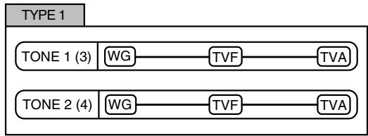
flowchart
graph TD
    A["TONE 1 (3)"] --> B["WG"]
    B --> C["TVF"]
    C --> D["TVA"]
    E["TONE 2 (4)"] --> F["WG"]
    F --> G["TVF"]
    G --> H["TVA"]
With this type, tones 1 and 2 (or 3 and 4) are independent. Use this type when you want to preserve PCM sounds or create and combine sounds for each tone.
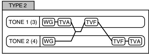
flowchart
graph TD
    A["TONE 1 (3)"] --> B["WG"] --> C["TVA"]
    D["TONE 2 (4)"] --> E["WG"] --> F["TVF"]
    C --> G["TVF"]
    F --> H["TVF"] --> I["TVA"]
This type stacks the two filters together to intensify the characteristics of the filters. The TVA for tone 1 (or 3) controls the volume balance between the two tones.
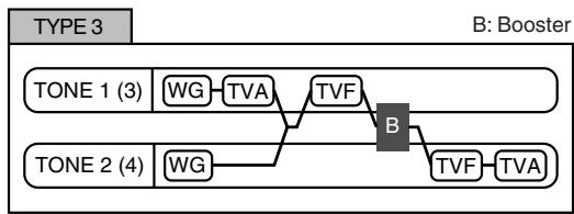
flowchart
graph TD
    A["TONE 1 (3)"] --> B["WG"]
    B --> C["TVA"]
    C --> D["TVF"]
    D --> E["B"]
    F["TONE 2 (4)"] --> G["WG"]
    G --> H["TVA"]
    H --> I["TVF"]
    I --> J["TVA"]
    J --> K["B: Booster"]
This type mixes the sound of tone 1 (3) and tone 2 (4), applies a filter, and then applies a booster to distort the waveform.
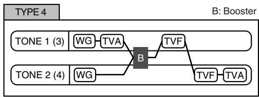
flowchart
graph LR
    A["TONE 1 (3)"] --> B["WG"]
    B --> C["TVA"]
    C --> D["B"]
    E["TONE 2 (4)"] --> F["WG"]
    F --> G["TVA"]
    G --> H["TVF"]
    H --> I["TVF"]
    I --> J["Booster"]
This type applies a booster to distort the waveform, and then combines the two filters. The TVA for tone 1 (or 3) controls the volume balance between the two tones and adjusts booster level.
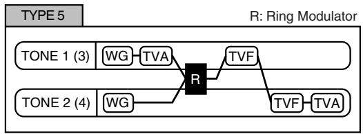
flowchart
graph LR
    A["TONE 1 (3)"] --> B["WG"] --> C["TVA"] --> D["R"]
    E["TONE 2 (4)"] --> F["WG"] --> G["TVA"] --> H["TVF"] --> I["TVF"] --> J["TVA"]
    style D fill:#000,stroke:#000,color:#fff
    style H fill:#000,stroke:#000,color:#fff
This type uses a ring modulator to create new overtones, and combines the two filters. The tone 1 (3) TVA will control the volume balance of the two tones, adjusting the depth of ring modulator.
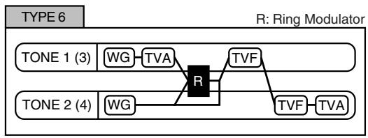
flowchart
graph LR
    A["TONE 1 (3)"] --> B["WG"] --> C["TVA"] --> D["R"]
    E["TONE 2 (4)"] --> F["WG"] --> G["TVA"] --> H["TVF"] --> I["TVF"] --> J["TVA"]
    style D fill:#000,stroke:#000,color:#fff
    style H fill:#000,stroke:#000,color:#fff
    style I fill:#000,stroke:#000,color:#fff
This type uses a ring modulator to create new overtones, and in addition mixes in the sound of tone 2 (4) and stacks the two filters. Since the ring-modulated sound can be mixed with tone 2 (4), tone 1 (3) TVA can adjust the amount of the ring-modulated sound.
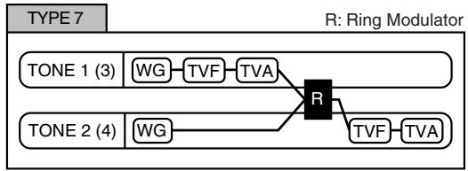
flowchart
graph TD
    A["TONE 1 (3)"] --> B["WG"] --> C["TVF"] --> D["TVA"]
    E["TONE 2 (4)"] --> F["WG"] --> G["R"]
    H["R"] --> I["TVF"] --> J["TVA"]
This type applies a filter to tone 1 (3) and ring-modulates it with tone 2 (4) to create new overtones.
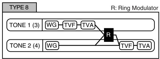
flowchart
graph TD
    A["TONE 1 (3)"] --> B["WG"] --> C["TVF"] --> D["TVA"]
    E["TONE 2 (4)"] --> F["WG"] --> G["TVF"] --> H["TVA"]
    I["R"] --> J["Central Node"]
    style I fill:#000,stroke:#000,color:#fff
    style J fill:#000,stroke:#000,color:#fff
This type sends the filtered tone 1 (3) and tone 2 (4) through a ring modulator, and then mixes in the sound of tone 2 (4) and applies a filter to the result.
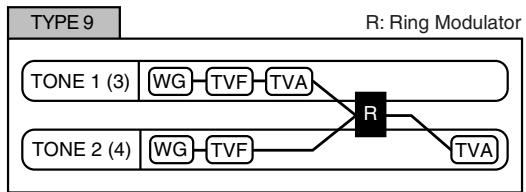
flowchart
graph TD
    A["TONE 1 (3)"] --> B["WG"] --> C["TVF"] --> D["TVA"]
    E["TONE 2 (4)"] --> F["WG"] --> G["TVF"] --> H["R"]
    H --> I["TVA"]
    style H fill:#000,stroke:#000,color:#fff
This type passes the filtered sound of each tone through a ring modulator to create new overtones. The tone 1 (3) TVA will control the volume balance of the two tones, adjusting the depth of ring modulator.
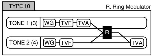
flowchart
graph TD
    A["TONE 1 (3)"] --> B["WG"] --> C["TVF"] --> D["TVA"]
    E["TONE 2 (4)"] --> F["WG"] --> G["TVF"] --> H["R"]
    H --> I["TVA"]
    style H fill:#000,stroke:#000,color:#fff
    style I fill:#000,stroke:#000,color:#fff
This type passes the filtered sound of each tone through a ring modulator to create new overtones, and also mixes in the sound of tone 2 (4). Since the ring-modulated sound can be mixed with tone 2 (4), tone 1 (3) TVA can adjust the amount of the ring-modulated sound.
NOTE
- When TYPE 2–10 is selected and one tone of a pair is turned off, the other tone will be sounded as TYPE 1 regardless of the displayed setting.
- If you limit the keyboard area in which a tone will sound (Keyboard Range p. 94) or limit the range of velocities for which it will sound (Velocity Range p. 95), the result in areas or ranges where the tone does not sound is just as if the tone had been turned off. This means that if TYPE 2–10 is selected and you create a keyboard area or velocity range in which one tone of a pair does not sound, notes played in that area or range will be sounded by the other tone as TYPE 1 regardless of the displayed setting.
Booster 1&2, 3&4 (Booster Gain 1&2, 3&4)
When a Structure Type of TYPE 3 or TYPE 4 is selected, you can adjust the depth of the booster. The booster increases the input signal in order to distort the sound. This creates the distortion effect frequently used with electric guitars. Higher settings will produce more distortion.
Value: 0, +6, +12, +18
Booster
The Booster is used to distort the incoming signal.
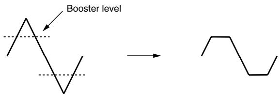
text_image
Booster levelIn addition to using this to create distortion, you can use the waveform (WG1) of one of the tones as an LFO which shifts the other waveform (WG2) upward or downward to create modulation similar to PWM (pulse width modulation). This parameter works best when you use it in conjunction with the Wave Gain parameter (p. 92).
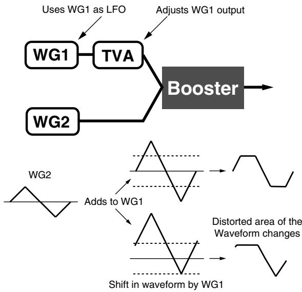
flowchart
graph TD
    A["Uses WG1 as LFO"] --> B["WG1"]
    C["Adjusts WG1 output"] --> D["TVA"]
    E["WG2"] --> F["Booster"]
    G["WG2"] --> H["Adds to WG1"]
    H --> I["Shift in waveform by WG1"]
    I --> J["Distorted area of the Waveform changes"]
Ring Modulator
A ring modulator multiplies the waveforms of two tones with each other, generating many new overtones (in harmonic partials) which were not present in either waveform. (Unless one of the waveforms is a sine wave, evenly-spaced frequency components will not usually be generated.)
As the pitch difference between the two waveforms changes the harmonic structure, the result will be an unpitched metallic sound. This function is suitable for creating metallic sounds such as bells.
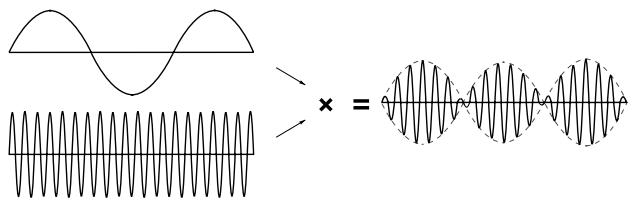
text_image
Mathematical expression showing wave interference and a sine wave equationKeyboard Fade Width Lower
This determines what will happen to the tone's level when a note that's lower than the tone's specified keyboard range is played. Higher settings produce a more gradual change in volume. If you don't want the tone to sound at all when a note below the keyboard range is played, set this parameter to "0."
Value: 0–127
Keyboard Range Lower
Specifies the lowest note that the tone will sound for each tone.
Value: C-1–UPPER
Keyboard Range Upper
Specifies the highest note that the tone will sound for each tone.
Value: LOWER-G9
NOTE
If you attempt to raise the lower key higher than the upper key, or to lower the upper key below the lower key, the other value will be automatically modified to the same setting.
Keyboard Fade Width Upper
This determines what will happen to the tone's level when a note that's higher than the tone's specified keyboard range is played. Higher settings produce a more gradual change in volume. If you don't want the tone to sound at all when a note above the keyboard range is played, set this parameter to "0."
Value: 0–127
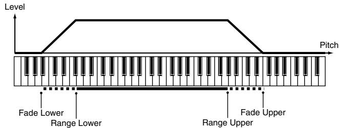
text_image
Level Pitch Fade Lower Range Lower Range Upper Fade UpperTMT Velocity Control (TMT Velocity Control Switch)
TMT Velocity Control determines whether a different tone is played (ON) or not (OFF) depending on the force with which the key is played (velocity).
When set to "RANDOM," the patch's constituent tones will sound randomly, regardless of any Velocity messages.
When set to "CYCLE," the patch's constituent tones will sound consecutively, regardless of any Velocity messages.
Value: OFF, ON, RANDOM, CYCLE
MEMO
Use “Velocity Range Lower” (p. 95) and “Velocity Range Upper” (p. 95) to specify the range of keyboard dynamics.
NOTE
If Velocity Range Lower and Velocity Range Upper are set to the same values, you won't be able to obtain any effect by setting TMT Velocity Control to "RANDOM" or "CYCLE."
NOTE
Instead of using Velocity, you can also have tones substituted using the Matrix Control (p. 109, p. 95). However, the keyboard velocity and the Matrix Control cannot be used simultaneously to make different tones to sound. When using the Matrix Control to switch tones, set the Velocity Control parameter to "OFF."
Velocity Fade Width Lower
This determines what will happen to the tone's level when the tone is played at a velocity lower than its specified velocity range. Higher settings produce a more gradual change in volume. If you want notes played outside the specified key velocity range to not be sounded at all, set this to "0."
Value: 0–127
Velocity Range Lower
This sets the lowest velocity at which the tone will sound. Make these settings when you want different tones to sound in response to notes played at different strengths.
Value: 1-UPPER
Velocity Range Upper
This sets the highest velocity at which the tone will sound. Make these settings when you want different tones to sound in response to notes played at different strengths.
Value: LOWER-127
NOTE
If you attempt to set the Lower velocity limit above the Upper, or the Upper below the Lower, the other value will automatically be adjusted to the same setting.
MEMO
When using the Matrix Control (p. 109) to have different tones played, set the lowest value (Lower) and highest value (Upper) of the value of the MIDI message used.
Velocity Fade Width Upper
This determines what will happen to the tone's level when the tone is played at a velocity greater than its specified velocity range. Higher settings produce a more gradual change in volume. If you want notes played outside the specified key velocity range to not be sounded at all, set this to "0."
Value: 0–127

text_image
Level Velocity Fade Lower Range Lower Range Upper Fade UpperTMT Control Switch
Use the Matrix Control (p. 109) to enable (ON), or disable (OFF) sounding of different tones.
Value: OFF, ON
NOTE
You can also cause different tones to sound in response to notes played at different strengths (velocity) on the keyboard (p. 95). However, the Matrix Control and the keyboard velocity cannot be used simultaneously to make different tones to sound. When you want to make the different tones to sound, set the Velocity Control parameter (p. 95) to "OFF."
Modifying Pitch (Pitch/Pitch Env)
Pitch
Tone Coarse Tune ★
Adjusts the pitch of the tone's sound up or down in semitone steps (+/-4 octaves).
Value: -48- +48
Tone Fine Tune ★
Adjusts the pitch of the tone's sound up or down in 1-cent steps (+/-50 cents).
Value: -50- +50

One cent is 1/100th of a semitone.
Random Pitch Depth
This specifies the width of random pitch deviation that will occur each time a key is pressed. If you do not want the pitch to change randomly, set this to "0." These values are in units of cents (1/100th of a semitone).
Value: 0, 1, 2, 3, 4, 5, 6, 7, 8, 9, 10, 20, 30, 40, 50, 60, 70, 80, 90, 100, 200, 300, 400, 500, 600, 700, 800, 900, 1000, 1100, 1200
Wave Pitch Key Follow
This specifies the amount of pitch change that will occur when you play a key one octave higher (i.e., 12 keys upward on the keyboard). If you want the pitch to rise one octave as on a conventional keyboard, set this to “+100.” If you want the pitch to rise two octaves, set this to “+200.” Conversely, set this to a negative value if you want the pitch to fall. With a setting of “0,” all keys will produce the same pitch.
Value: -200, -190, -180, -170, -160, -150, -140, -130, -120, -110, -100, -90, -80, -70, -60, -50, -40, -30, -20, -10, 0, +10, +20, +30, +40, +50, +60, +70, +80, +90, +100, +110, +120, +130, +140, +150, +160, +170, +180, +190, +200
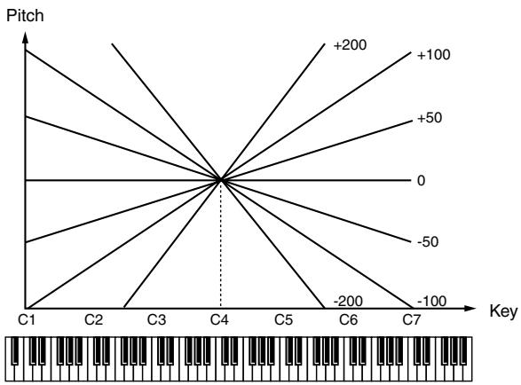
line
| Key | Pitch | | --- | ----- | | C1 | 0 | | C2 | 0 | | C3 | 0 | | C4 | 0 | | C5 | 0 | | C6 | 0 | | C7 | 0 |Pitch Bend Range Up
Specifies the degree of pitch change in semitones when the Pitch Bend lever is all the way right. For example, if this parameter is set to "12," the pitch will rise one octave when the pitch bend lever is moved to the right-most position.
Value: 0- +48
Pitch Bend Range Down
Specifies the degree of pitch change in semitones when the Pitch Bend lever is all the way left. For example if this is set to “-48” and you move the pitch bend lever all the way to the left, the pitch will fall 4 octaves.
Value: -48–0
Pitch Env Velocity Sens
Keyboard playing dynamics can be used to control the depth of the pitch envelope. If you want the pitch envelope to have more effect for strongly played notes, set this parameter to a positive (+) value. If you want the pitch envelope to have less effect for strongly played notes, set this to a negative (-) value.
Value: -63- +63
Pitch Env Time 1 Velocity Sens
This allows keyboard dynamics to affect the Time 1 of the Pitch envelope. If you want Time 1 to be speeded up for strongly played notes, set this parameter to a positive (+) value. If you want it to be slowed down, set this to a negative (-) value.
Value: -63- +63
Pitch Env Time 4 Velocity Sens
Use this parameter when you want key release speed to affect the Time 4 value of the pitch envelope. If you want Time 4 to be speeded up for quickly released notes, set this parameter to a positive (+) value. If you want it to be slowed down, set this to a negative (-) value.
Value: -63- +63
Pitch Env Time Key Follow
Use this setting if you want the pitch envelope times (Time 2–Time 4) to be affected by the keyboard location. Based on the pitch envelope times for the C4 key, positive (+) settings will cause notes higher than C4 to have increasingly shorter times, and negative (-) settings will cause them to have increasingly longer times. Larger settings will produce greater change.
Value: -100, -90, -80, -70, -60, -50, -40, -30, -20, -10, 0, +10, +20, +30, +40, +50, +60, +70, +80, +90, +100
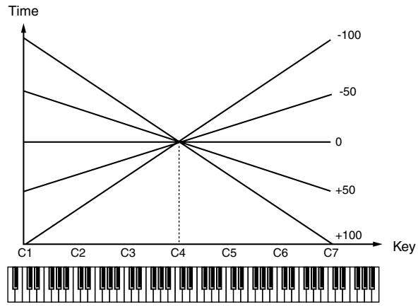
line
| Key | Time | |-----|-------| | C1 | -100 | | C2 | -50 | | C3 | 0 | | C4 | +50 | | C5 | +100 | | C6 | -50 | | C7 | -100 |Hold Bend
This specifies whether pitch bend will be disabled (ON) or enabled (OFF) while it's being held by the pedal and during the release portion of the sound.
Value: OFF, ON
Bend Mode
Specifies what will happen when you operate the pitch bend lever.
Value
| NORMAL: | The pitch bend lever will apply in the conventional way. |
| TOUCH: | Moving the pitch bend lever will change the pitch smoothly, but the pitch will instantly return to center if you return the lever even slightly. |
| CATCH: | If you play a note-on with the pitch bend lever already moved, the pitch will sound at the center position. The pitch will change only after the lever has passed through the center position. |
| LAST: | The pitch bend lever will apply only to the last-played note. |
| CATCH+LAST: | The operation of “CATCH” and “LAST” will be combined. |
Bend Mode Control
This specifies the CC (control change) whose value is used to switch the pitch bend lever's operation between the mode specified by Bend Mode (control values 64 or higher) and conventional operation (control values 63 or lower).
Value: CC01–31, CC32(OFF), CC33–95
Pitch Env (Pitch Envelope)
Pitch Env Depth
Adjusts the effect of the Pitch Envelope. Higher settings will cause the pitch envelope to produce greater change. Negative (-) settings will invert the shape of the envelope.
Value: -12- +12
Pitch Env Time 1-4 ★
Specify the pitch envelope times (Time 1–Time 4). Higher settings will result in a longer time until the next pitch is reached. (For example, Time 2 is the time over which the pitch changes from Level 1 to Level 2.)
Value: 0–127
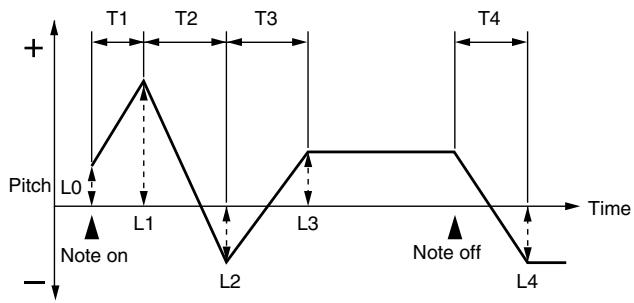
line
| Time | Pitch | Annotation | |------|-------|------------| | T1 | + | | | T2 | + | | | T3 | + | | | T4 | + | | | L0 | - | L0 | | L1 | - | L1 | | L2 | - | L2 | | L3 | + | | | L4 | - | | Note on, Note offT: Time L: Level
Pitch Env Level 0-4
Specify the pitch envelope levels (Level 0–Level 4). It determines how much the pitch changes from the reference pitch (the value set with Coarse Tune or Fine Tune on the Pitch screen) at each point. Positive (+) settings will cause the pitch to be higher than the standard pitch, and negative (-) settings will cause it to be lower.
Value: -63- +63
Modifying the Brightness of a Sound with a Filter (TVF/TVF Env)
TVF
Filter Type
Selects the type of filter. A filter cuts or boosts a specific frequency region to change a sound's brightness, thickness, or other qualities.
Value
OFF: No filter is used.
LPF: Low Pass Filter. This reduces the volume of all frequencies above the cutoff frequency (Cutoff Freq) in order to round off, or un-brighten the sound. This is the most common filter used in synthesizers.
BPF: Band Pass Filter. This leaves only the frequencies in the region of the cutoff frequency (Cutoff Freq), and cuts the rest. This can be useful when creating distinctive sounds.
HPF: High Pass Filter. This cuts the frequencies in the region below the cutoff frequency (Cutoff Freq). This is suitable for creating percussive sounds emphasizing their higher tones.
PKG: Peaking Filter. This emphasizes the frequencies in the region of the cutoff frequency (Cutoff Freq). You can use this to create wah-wah effects by employing an LFO to change the cutoff frequency cyclically.
LPF2: Low Pass Filter 2. Although frequency components above the Cutoff frequency (Cutoff Freq) are cut, the sensitivity of this filter is half that of the LPF. This makes it a comparatively warmer low pass filter. This filter is good for use with simulated instrument sounds such as the acoustic piano.
LPF3: Low Pass Filter 3. Although frequency components above the Cutoff frequency (Cutoff Freq) are cut, the sensitivity of this filter changes according to the Cutoff frequency. While this filter is also good for use with simulated acoustic instrument sounds, the nuance it exhibits differs from that of the LPF2, even with the same TVF Envelope settings.
NOTE
If you set "LPF2" or "LPF3," the setting for the Resonance parameter will be ignored (p. 98).
Cutoff Frequency ★
Selects the frequency at which the filter begins to have an effect on the waveform's frequency components.
Value: 0–127
With “LPF/LPF2/LPF3” selected for the Filter Type parameter, lower cutoff frequency settings reduce a tone’s upper harmonics for a more rounded, warmer sound. Higher settings make it sound brighter.
If “BPF” is selected, harmonic components will change depending on the TVF Cutoff Frequency setting. This can be useful when creating distinctive sounds.
With “HPF” selected, higher Cutoff Frequency settings will reduce lower harmonics to emphasize just the brighter components of the sound.
With "PKG" selected, the harmonics to be emphasized will vary depending on Cutoff Frequency setting.
TIP
To edit the overall patch while preserving the relative differences in the Cutoff Frequency values set for each tone, set the Cutoff Offset parameter (p. 90).
Resonance ★
Emphasizes the portion of the sound in the region of the cutoff frequency, adding character to the sound. Excessively high settings can produce oscillation, causing the sound to distort.
Value: 0–127
TIP
To edit the overall patch while preserving the relative differences in the Resonance values set for each tone, set the Resonance Offset parameter (p. 91).
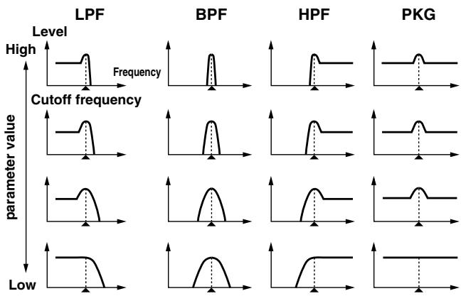
line
| Parameter Value | LPF Level | BPF Level | HPF Level | PKG Level | | --------------- | --------- | --------- | --------- | --------- | | High | High | High | High | High | | Cutoff frequency | Low | Low | Low | Low | | parameter value | Low | Low | Low | Low |TVF Cutoff Key follow
Use this parameter if you want the cutoff frequency to change according to the key that is pressed. Relative to the cutoff frequency at the C4 key (center C), positive (+) settings will cause the cutoff frequency to rise for notes higher than C4, and negative (-) settings will cause the cutoff frequency to fall for notes higher than C4. Larger settings will produce greater change.
| Value: | -200, -190, -180, -170, -160, -150, -140, -130, -120, -110, -100, -90, -80, -70, -60, -50, -40, -30, -20, -10, 0, +10, +20, +30, +40, +50, +60, +70, +80, +90, +100, +110, +120, +130, +140, +150, +160, +170, +180, +190, +200 |
Cutoff frequency (Octave)
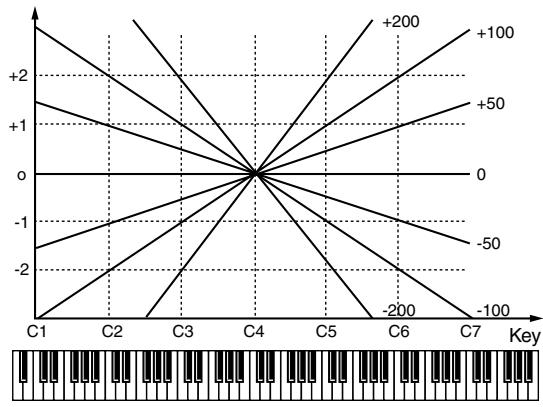
line
| Key | Value | |-----|-------| | C1 | +2 | | C2 | +1 | | C3 | +0 | | C4 | 0 | | C5 | -1 | | C6 | -2 | | C7 | -3 |Cutoff Velocity Curve
Selects one of the following seven curves that determine how keyboard playing dynamics (velocity) influence the cutoff frequency. Set this to “FIXED” if you don’t want the Cutoff frequency to be affected by the keyboard velocity.
Value: FIXED, 1–7

text_image
1 2 3 4 5 6 7Cutoff Velocity Sens
Use this parameter when changing the cutoff frequency to be applied as a result of changes in playing velocity. If you want strongly played notes to raise the cutoff frequency, set this parameter to positive (+) settings. If you want strongly played notes to lower the cutoff frequency, use negative (-) settings.
Value: -63- +63
TIP
To edit the overall patch while preserving the relative differences in the Cutoff Frequency Velocity Sensitivity values set for each tone, set the Velocity Sens Offset parameter (p. 91). However, this setting is shared by the Level Velocity Sens parameter (p. 100).
Resonance Velocity Sens
This allows keyboard velocity to modify the amount of Resonance. If you want strongly played notes to have a greater Resonance effect, set this parameter to positive (+) settings. If you want strongly played notes to have less Resonance, use negative (-) settings.
Value: -63- +63
TVF Env Velocity Curve
Selects one of the following 7 curves that will determine how keyboard playing dynamics will affect the TVF envelope. Set this to "FIXED" if you don't want the TVF Envelope to be affected by the keyboard velocity.
Value: FIXED, 1–7

text_image
1 2 3 4 5 6 7TVF Env Velocity Sens
Specifies how keyboard playing dynamics will affect the depth of the TVF envelope. Positive (+) settings will cause the TVF envelope to have a greater effect for strongly played notes, and negative (-) settings will cause the effect to be less.
Value: -63- +63
TVF Env Time 1 Velocity Sens
This allows keyboard dynamics to affect the Time 1 of the TVF envelope. If you want Time 1 to be speeded up for strongly played notes, set this parameter to a positive (+) value. If you want it to be slowed down, set this to a negative (-) value.
Value: -63- +63
TVF Env Time 4 Velocity Sens
The parameter to use when you want key release speed to control the Time 4 value of the TVF envelope. If you want Time 4 to be speeded up for quickly released notes, set this parameter to a positive (+) value. If you want it to be slowed down, set this to a negative (-) value.
Value: -63- +63
Specifies the depth of the TVF envelope. Higher settings will cause the TVF envelope to produce greater change. Negative (-) settings will invert the shape of the envelope.
Value: -63- +63
TVF Env Time Key Follow
Use this setting if you want the TVF envelope times (Time 2–Time 4) to be affected by the keyboard location. Based on the TVF envelope times for the C4 key (center C), positive (+) settings will cause notes higher than C4 to have increasingly shorter times, and negative (-) settings will cause them to have increasingly longer times. Larger settings will produce greater change.
Value: -100, -90, -80, -70, -60, -50, -40, -30, -20, -10, 0, +10,
+20, +30, +40, +50, +60, +70, +80, +90, +100
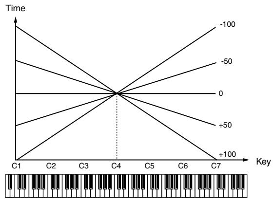
line
| Key | Time | | --- | ---- | | C1 | -100 | | C2 | -50 | | C3 | 0 | | C4 | +50 | | C5 | +100 | | C6 | -50 | | C7 | -100 |TVF Env Time 1-4 ★
Specify the TVF envelope times (Time 1–Time 4). Higher settings will lengthen the time until the next cutoff frequency level is reached. (For example, Time 2 is the time over which Level 1 will change to Level 2.)
Value: 0–127
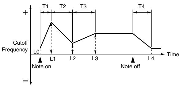
line
| Time | Cutoff Frequency | |------|------------------| | L0 | 0 | | L1 | T1 | | L2 | 0 | | L3 | 0 | | L4 | 0 |T: Time L: Level
TVF Env Level 0-4
Specify the TVF envelope levels (Level 0–Level 4). These settings specify how the cutoff frequency will change at each point, relative to the standard cutoff frequency (the cutoff frequency value specified in the TVF screen).
Value: 0–127
Adjusting the Volume (TVA/TVA Env)
TVA
Tone Level ★
Sets the volume of the tone. This setting is useful primarily for adjusting the volume balance between tones.
Value: 0–127
Level Velocity Curve (TVA Level Velocity Curve)
You can select from seven curves that determine how keyboard playing strength will affect the volume. If you do not want the volume of the tone to be affected by the force with which you play the key, set this to "FIXED."
Value: FIXED, 1–7

text_image
1 2 3 4 5 6 7Level Velocity Sens (TVA Level Velocity Sensitivity)
Set this when you want the volume of the tone to change depending on the force with which you press the keys. Set this to a positive (+) value to have the changes in tone volume increase the more forcefully the keys are played; to make the tone play more softly as you play harder, set this to a negative (-) value.
Value: -63- +63
TIP
If you wish to make adjustments to the entire patch while maintaining the relative values of TVA Level Velocity Sensitivity among tones, adjust the Velocity Sens Offset parameter (p. 91). However, this setting is shared by the Cutoff Velocity Sens parameter (p. 99).
Bias
Bias causes the volume to be affected by the keyboard position. This is useful for changing volume through keyboard position (pitch) when playing acoustic instruments.
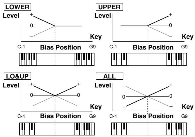
Bias Level
Adjusts the angle of the volume change that will occur in the selected Bias Direction. Larger settings will produce greater change. Negative (-) values will invert the change direction.
Value: -100, -90, -80, -70, -60, -50, -40, -30, -20, -10, 0, +10, +20, +30, +40, +50, +60, +70, +80, +90, +100
Bias Position
Specifies the key relative to which the volume will be modified.
Value: C-1–G9
Bias Direction
Selects the direction in which change will occur starting from the Bias Position.
Value
LOWER: The volume will be modified for the keyboard area below the Bias Point.
UPPER: The volume will be modified for the keyboard area above the Bias Point.
LO&UP: The volume will be modified symmetrically toward the left and right of the Bias Point.
ALL: The volume changes linearly with the bias point at the center.
Tone Pan ★
Sets the pan of the tone. "L64" is far left, "0" is center, and "63R" is far right.
Value: L64-0-63R
Tone Pan Key Follow
Use this parameter if you want key position to affect panning. Positive (+) settings will cause notes higher than C4 key (center C) to be panned increasingly further toward the right, and negative (-) settings will cause notes higher than C4 key (center C) to be panned toward the left. Larger settings will produce greater change.
Value: -100- +100
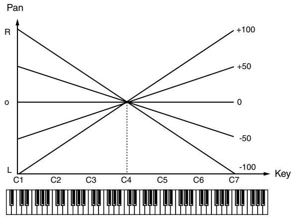
line
| Key | R | |-----|------| | C1 | L | | C2 | -50 | | C3 | -100 | | C4 | 0 | | C5 | +50 | | C6 | +100 | | C7 | +50 |Random Pan Depth
Use this parameter when you want the stereo location to change randomly each time you press a key. Higher settings will produce a greater amount of change.
Value: 0–63
Alternate Pan Depth
This setting causes panning to be alternated between left and right each time a key is pressed. Higher settings will produce a greater amount of change. "L" or "R" settings will reverse the order in which the pan will alternate between left and right. For example if two tones are set to "L" and "R" respectively, the panning of the two tones will alternate each time they are played.
Value: L63-0-63R
NOTE
When any value from Type “2”–“10” is selected for the Structure parameter in the Pan Key Follow, Rnd Pan Depth, Alter Pan Depth parameter settings, the output of tones 1 and 2 are joined in tone 2, and the output of tones 3 and 4 are joined in tone 4. For this reason, tone 1 will follow the settings of tone 2, and tone 3 will follow the settings of tone 4 (p. 92).
TVA Env (TVA Envelope)
TVA Env Time 1 Velocity Sens
This allows keyboard dynamics to affect the Time 1 of the TVA envelope. If you want Time 1 to be speeded up for strongly played notes, set this parameter to a positive (+) value. If you want it to be slowed down, set this to a negative (-) value.
Value: -63- +63
TVA Env Time 4 Velocity Sens
The parameter to use when you want key release speed to control the Time 4 value of the TVA envelope. If you want Time 4 to be speeded up for quickly released notes, set this parameter to a positive (+) value. If you want it to be slowed down, set this to a negative (-) value.
Value: -63- +63
TVA Env Time Key Follow
Use this setting if you want the TVA envelope times (Time 2–Time 4) to be affected by the keyboard location. Based on the TVA envelope times for the C4 key (center C), positive (+) settings will cause notes higher than C4 to have increasingly shorter times, and negative (-) settings will cause them to have increasingly longer times. Larger settings will produce greater change.
Value: -100, -90, -80, -70, -60, -50, -40, -30, -20, -10, 0, +10, +20, +30, +40, +50, +60, +70, +80, +90, +100
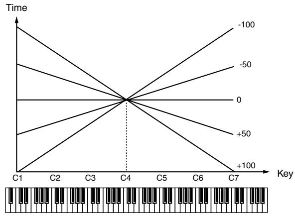
line
| Key | Time | |-----|-------| | C1 | -100 | | C2 | -50 | | C3 | 0 | | C4 | +50 | | C5 | +100 | | C6 | -50 | | C7 | -100 |TVA Env Time 1-4 ★
Specify the TVA envelope times (Time 1– Time 4). Higher settings will lengthen the time until the next volume level is reached. (For example, Time 2 is the time over which Level 1 will change to Level 2.)
Value: 0–127
TVA Env Level 1-3
Specify the TVA envelope levels (Level 1–Level 3). These settings specify how the volume will change at each point, relative to the standard volume (the Tone Level value specified in the TVA screen).
Value: 0–127
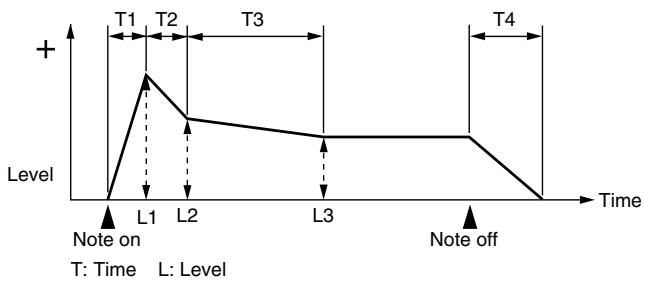
line
| Time | Level | |------|-------| | T1 | + | | T2 | + | | T3 | + | | T4 | - | | L1 | + | | L2 | + | | L3 | + | | Note off | - |Output
Tone Output Assign
Specifies how the direct sound of each tone will be output.
Value:
PFX: Output through patch multi-effects.
DRY: Output without passing through patch multi-effects.
Tone Output Level
Specifies the signal level of each tone.
Value: 0–127
Tone Chorus Send Level
Specifies the level of the signal sent to the chorus for each tone.
Value: 0–127
Tone Reverb Send Level
Specifies the level of the signal sent to the reverb for each tone.
Value: 0–127
Modulating Sounds (LFO1/2/Step LFO)
MEMO
An LFO (Low Frequency Oscillator) causes change over a cycle in a sound. Each tone has two LFOs (LFO1/LFO2), and these can be used to cyclically change the pitch, cutoff frequency and volume to create modulation-type effects such as vibrato, wah and tremolo. Both LFOs have the same parameters so only one explanation is needed.
LFO1/2
Waveform (LFO1/LFO2 Waveform)
Selects the waveform of the LFO.
Value
SIN: Sine wave
TRI: Triangle wave
SAW-U: Sawtooth wave
SAW-D: Sawtooth wave (negative polarity)
SQR: Square wave
RND: Random wave
BND-U: Once the attack of the waveform output by the LFO is allowed to develop in standard fashion, the waveform then continues without further change.
BND-D: Once the decay of the waveform output by the LFO is allowed to develop in standard fashion, the waveform then continues without further change.
TRP: Trapezoidal wave
S&H: Sample & Hold wave (one time per cycle, LFO value is changed)
CHAOS: Chaos wave
VSIN: Modified sine wave. The amplitude of a sine wave is randomly varied once each cycle.
STEP: A waveform generated by the data specified by LFO Step 1–64. This produces stepped change with a fixed pattern similar to a step modulator.
NOTE
If you set this to "BND-U" or "BND-D," you must turn the Key Trigger parameter to "ON." If this is "OFF," it will have no effect.
Rate (LFO1/LFO2 Rate) ★
Adjusts the modulation rate, or speed, of the LFO.
Value: 0–127, Note
LFO Rate sets the beat length for the synchronized tempo is synchronized with the tempo set in a sequencer.
(Example)
For a tempo of 120 (120 quarter notes occur in 1 minute (60 seconds))
| Setting | LFO Rate |
| ♩ (half note) | 1 second (60 / 60 =1 (second)) |
| ♩ (quarter note) | 0.5 seconds (60 / 120= 0.5 (seconds)) |
| ♩ (eighth note) | 0.25 seconds (60 / 240= 0.25 (seconds)) |
NOTE
This setting will be ignored if the Waveform parameter is set to "CHAOS."
Rate Detune (LFO1/LFO2 Rate Detune)
LFO Rate Detune makes subtle changes in the LFO cycle rate (Rate parameter) each time a key is pressed. Higher settings will cause greater change. This parameter is invalid when Rate is set to “note.”
Value: 0–127
Offset (LFO1/LFO2 Offset)
Raises or lowers the LFO waveform relative to the central value (pitch or cutoff frequency). Positive (+) settings will move the waveform so that modulation will occur from the central value upward. Negative (-) settings will move the waveform so that modulation will occur from the central value downward.
Value: -100, -50, 0, +50, +100
Delay Time (LFO1/LFO2 Delay Time)
Delay Time (LFO Delay Time) specifies the time elapsed before the LFO effect is applied (the effect continues) after the key is pressed (or released).
Value: 0–127
cf.
After referring to “How to Apply the LFO” (p. 104), change the setting until the desired effect is achieved.
TIP
When using violin, wind, or certain other instrument sounds in a performance, rather than having vibrato added immediately after the sounds are played, it can be effective to add the vibrato after the note is drawn out somewhat. If you set the Delay Time in conjunction with the Pitch Depth parameter and Rate parameter, the vibrato will be applied automatically following a certain interval after the key is pressed. This effect is called
Delay Vibrato.
LFO1/LFO2 Delay Time Key Follow
Adjusts the value for the Delay Time parameter depending on the key position, relative to the C4 key (center C). To decrease the time that elapses before the LFO effect is applied (the effect is continuous) with each higher key that is pressed in the upper registers, select a positive value; to increase the elapsed time, select a negative value. Larger settings will produce greater change. If you do not want the elapsed time before the LFO effect is applied (the effect is continuous) to change according to the key pressed, set this to "0."
Value: -100, -90, -80, -70, -60, -50, -40, -30, -20, -10, 0, +10, +20, +30, +40, +50, +60, +70, +80, +90, +100
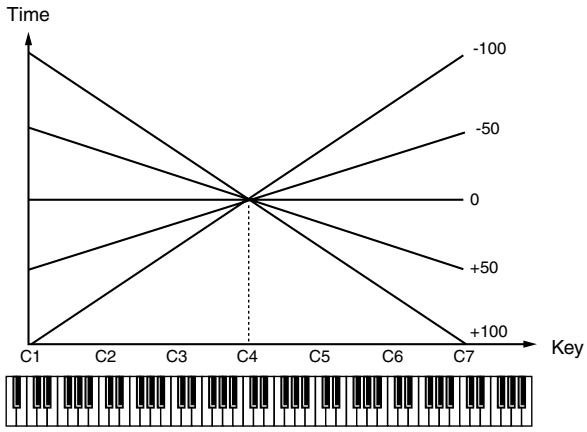
line
| Key | Time | |-----|-------| | C1 | 0 | | C2 | -50 | | C3 | -100 | | C4 | 0 | | C5 | +50 | | C6 | +100 | | C7 | +100 |Fade Mode (LFO1/LFO2 Fade Mode)
Specifies how the LFO will be applied.
Value: ON <, ON >, OFF <, OFF >
After referring to “How to Apply the LFO” (p. 104), change the setting until the desired effect is achieved.
Fade Time (LFO1/LFO2 Fade Time)
Specifies the time over which the LFO amplitude will reach the maximum (minimum).
Value: 0–127
After referring to “How to Apply the LFO” (p. 104), change the setting until the desired effect is achieved.
Key Trigger (LFO1/LFO2 Key Trigger)
This specifies whether the LFO cycle will be synchronized to begin when the key is pressed (ON) or not (OFF).
Value: OFF, ON
Pitch Depth (LFO1/LFO2 Pitch Depth) ★
Specifies how deeply the LFO will affect pitch.
Value: -63- +63
Specifies how deeply the LFO will affect the cutoff frequency.
Value: -63- +63
TVA Depth (LFO1/LFO2 TVA Depth) ★
Specifies how deeply the LFO will affect the volume.
Value: -63- +63
Pan Depth (LFO1/LFO2 Pan Depth) ★
Specifies how deeply the LFO will affect the pan.
Value: -63- +63

Positive (+) and negative (-) settings for the Depth parameter result in differing kinds of change in pitch and volume. For example, if you set the Depth parameter to a positive (+) value for one tone, and set another tone to the same numerical value, but make it negative (-), the modulation phase for the two tones will be the reverse of each other. This allows you to shift back and forth between two different tones, or combine it with the Pan setting to cyclically change the location of the sound image.
NOTE
When the Structure parameter is set to any value from “2” through “10,” the output of tones 1 and 2 will be combined into tone 2, and the output of tones 3 and 4 will be combined into tone 4. This applies to the Pan Depth parameter settings. For this reason, tone 1 will follow the settings of tone 2, and tone 3 will follow the settings of tone 4 (p. 92).
Step LFO
LFO Step Type
When generating an LFO waveform from the data specified in LFO Step1–64, specify whether the level will change abruptly at each step or will be connected linearly.
Value: TYPE1 (stair-step change), TYPE2 (linear change)
Step 1-64 (LFO Step 1-64)
Specifies the data for the Step LFO. If the LFO Pitch Depth is +63, each +1 unit of the step data corresponds to a pitch of +50 cents.
Value: -36- +36
LFO End Step
Specifies the number of LFO steps.
Value: 1, 2, 4, 8, 16, 32, 64
How to Apply the LFO
- Apply the LFO gradually after the key is pressed
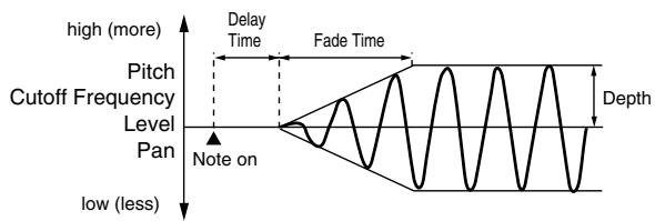
line
| Pitch Level | Cutoff Frequency | Delay Time | Fade Time | | ----------- | ---------------- | ---------- | --------- | | low (less) | - | - | - | | Level | - | - | - | | High | - | - | - |Fade Mode: ON <
Delay Time: The time from when the keyboard is played until the LFO begins to be applied.
Fade Time: The time over which the LFO amplitude will reach the maximum after the Delay Time has elapsed.
- Apply the LFO immediately when the key is pressed, and then gradually begin to decrease the effect
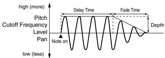
line
| Time Segment | Value | | ------------ | ----- | | High | >10 | | Low | <10 | | Mid | ~10 | | Late | >10 | | Bottom | <10 |Fade Mode: ON >
Delay Time: The time that the LFO will continue after the keyboard is played.
Fade Time: The time over which the LFO amplitude will reach the minimum after the Delay Time has elapsed.
- Apply the LFO gradually after the key is released
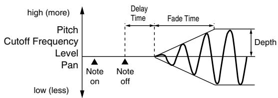
line
| Level | Value | |-------|-------| | high | more | | low | less | | Note on | on | | Note off | off |Fade Mode: OFF <
Delay Time: The time from when the keyboard is released until the LFO begins to be applied.
Fade Time: The time over which the LFO amplitude will reach the maximum after the Delay Time has elapsed.
- Apply the LFO from when the key is pressed until it is released, and gradually begin to decrease the effect when the key is released
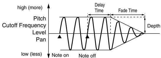
line
| Point Label | Description | | ----------- | ------------------- | | Peak | High (more) | | Low Point | Note on | | Mid Point | Level Pan | | Peak | Pitch Cutoff Frequency | | End Point | Note off |Fade Mode: OFF >
Delay Time: The time that the LFO will continue after the keyboard is released.
Fade Time: The time over which the LFO amplitude will reach the minimum after the Delay Time has elapsed.
Apply Portamento or Legato to the Sound (Solo/Porta)
Mono/Poly
Specifies whether the patch will play polyphonically (POLY) or monophonically (MONO). The “MONO” setting is effective when playing a solo instrument patch such as sax or flute.
Value
MONO: Only the last-played note will sound.
POLY: Two or more notes can be played simultaneously.
Legato Switch
Legato Switch is valid when the Mono/Poly parameter is set to "MONO." This setting specifies whether the Legato Switch will be used (LEGATO) or not (OFF).
With the Legato Switch parameter “LEGATO,” pressing a key while continuing to press a previous key causes the note to change pitch to the pitch of the most recently pressed key, sounding all the while. This creates a smooth transition between notes, which is effective when you wish to simulate the hammering-on and pulling-off techniques used by a guitarist.
If you choose "SUSTAIN," the legato effect is applied while you hold down the hold pedal.
Value: OFF, LEGATO, SUSTAIN, LEGATO+SUSTAIN
Legato Retrigger (Legato Retrigger Switch)
Legato Retrigger is available if the Mono/Poly parameter is set to "MONO" and the Legato Switch parameter has a setting other than "OFF." The setting determines whether sounds are replayed (ON) or not (OFF) when performing legato. Normally you will leave this parameter "ON." If this is turned "OFF," pressing a second key while still holding down the first key will cause only the pitch to change; there will be no attack sound for the second key you pressed. Set this to "OFF" when performing wind and string phrases or when using modulation with the mono synth keyboard sound. If this is set to "AUTO," retriggering will occur only if you play a key that is one octave or farther away.
Value: OFF, ON, AUTO
Let's say you have the Legato Switch set to "LEGATO," and the Legato Retrigger set to "OFF." When you try to sound a legato (by pressing a higher key while a lower key is held down), the pitch may sometimes not be able to rise all the way to the intended pitch (stopping instead at an intermediate pitch). This can occur because the limit of pitch rise, as determined at the wave level, has been exceeded. Additionally, if differing upper pitch limits are used for the waves of a Patch that uses multiple tones, it may stop being heard in MONO. When making large pitch changes, set the Legato Retrigger to "ON."
Portamento Switch
Specifies whether the portamento effect will be applied (ON) or not (OFF).
Value: OFF, ON
Portamento
Portamento is an effect which smoothly changes the pitch from the first-played key to the next-played key. By applying portamento when the Mono/Poly parameter is “MONO,” you can simulate slide performance techniques on a violin or similar instrument.
Portamento Mode
Specifies the performance conditions for which portamento will be applied.
Value
NORMAL: Portamento will always be applied.
LEGATO: Portamento will be applied only when you play legato (i.e., when you press the next key before releasing the previous key).
Portamento Type
Specifies the type of portamento effect.
Value
RATE: The time it takes will depend on the distance between the two pitches.
TIME: The time it takes will be constant, regardless of how far apart in pitch the notes are.
Portamento Start
When another key is pressed during a pitch change produced by portamento, a new pitch change will begin. This setting specifies the pitch at which the change will begin.
Value
PITCH: Starts a new portamento when another key is pressed while the pitch is changing.
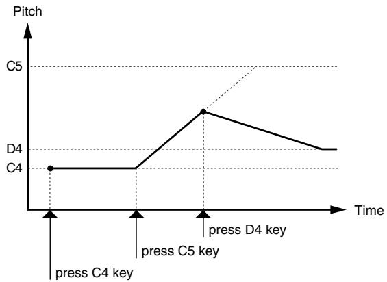
line
| Time Point | Pitch | | ---------------- | ----- | | press C4 key | C4 | | press C5 key | C5 | | press D4 key | D4 |NOTE: Portamento will begin a new from the pitch where the current change would end.
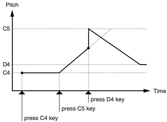
line
| Time Point | Pitch | | ---------------- | ----- | | press C4 key | C4 | | press C5 key | C5 | | press D4 key | D4 |Portamento Time
When portamento is used, this specifies the time over which the pitch will change. Higher settings will cause the pitch change to the next note to take more time.
Value: 0–127
Miscellaneous Settings (Misc)
Tone Delay Mode
Selects the type of tone delay.
Value
NORM: The tone begins to play after the time specified in the Delay Time parameter has elapsed.
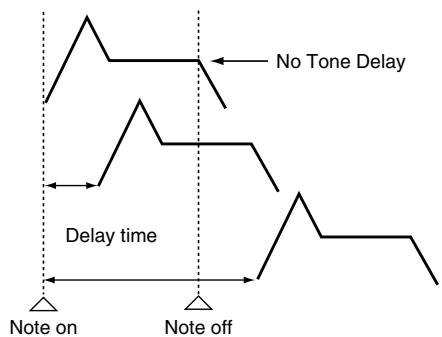
flowchart
graph TD
    A["Note on"] --> B["No Tone Delay"]
    B --> C["Note off"]
    C --> D["Delay time"]
    D --> E["Note on"]
    style A fill:#f9f,stroke:#333
    style B fill:#ccf,stroke:#333
    style C fill:#cfc,stroke:#333
    style D fill:#fcc,stroke:#333
    style E fill:#ffc,stroke:#333
HOLD: Although the tone begins to play after the time specified in the Delay Time parameter has elapsed, if the key is released before the time specified in the Delay Time parameter has elapsed, the tone is not played.
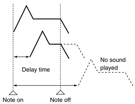
flowchart
graph TD
    A["Note on"] --> B["Delay time"]
    B --> C["Note off"]
    D["No sound played"] -.-> E["End"]
OFF-N:
Rather than being played while the key is pressed, the tone begins to play once the period of time specified in the Delay Time parameter has elapsed after release of the key. This is effective in situations such as when simulating noises from guitars and other instruments.
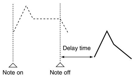
text_image
Note on Note off Delay timeOFF-D:
Rather than being played while the key is pressed, the tone begins to play once the period of time specified in the Delay Time parameter has elapsed after release of the key. Here, however, changes in the TVA Envelope begin while the key is pressed, which in many cases means that only the sound from the release portion of the envelope is heard.
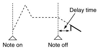
text_image
Note on Note off Delay timeNOTE
If you have selected a waveform that is a decay-type sound (i.e., a sound that fades away naturally even if the key is not released), selecting “OFF-N” or “OFF-D” may result in no sound being heard.
Tone Delay
This produces a time delay between the moment a key is pressed (or released), and the moment the tone actually begins to sound. You can also make settings that shift the timing at which each tone is sounded. This differs from the Delay in the internal effects, in that by changing the sound qualities of the delayed tones and changing the pitch for each tone, you can also perform arpeggio-like passages just by pressing one key. You can also synchronize the tone delay time to the tempo of the sequencer.
NOTE
If you are not going to use Tone Delay, set the Delay Mode parameter to "NORM" and Delay Time parameter to "0."
- If the Structure parameters set in the range of "2"–"10," the output of tones 1 and 2 will be combined into tone 2, and the output of tones 3 and 4 will be combined into tone 4. For this reason, tone 1 will follow the settings of tone 2, and tone 3 will follow the settings of tone 4 (p. 92).
Tone Delay Time
Specifies the time from when the key is pressed (or if the Delay Mode parameter is set to "OFF-N" or "OFF-D," the time from when the key is released) until when the tone will sound.
Value: 0–127, Note
Tone Delay Time specifies the beat length for the synchronized tempo when the tempo that specifies the elapsed time until the tone is sounded (Patch Tempo) is synchronized with the tempo set in a sequencer.
(Example)
For a tempo of 120 (120 quarter notes occur in 1 minute (60 seconds))
| Setting | Delay time |
| ♩ (half note) | 1 second (60 / 60 =1 (second)) |
| ♩ (quarter note) | 0.5 seconds (60 / 120= 0.5 (seconds)) |
| ♩ (eighth note) | 0.25 seconds (60 / 240= 0.25 (seconds)) |
Tone Env Mode
When a loop waveform (p. 88) is selected, the sound will normally continue as long as the key is pressed. If you want the sound to decay naturally even if the key remains pressed, set this to "NO SUS."
Range: NO SUS, SUST
NOTE
If a one-shot type Wave (p. 88) is selected, it will not sustain even if this parameter is set to "SUST."
Tone Receive Bender (Tone Receive Pitch Bend Switch)
For each tone, specify whether MIDI Pitch Bend messages will be received (ON), or not (OFF).
Value: OFF, ON
Tone Receive Expression (Tone Receive Expression Switch)
For each tone, specify whether MIDI Expression messages will be received (ON), or not (OFF).
Value: OFF, ON
Tone Receive Hold-1 (Tone Receive Hold Switch)
For each tone, specify whether MIDI Hold-1 messages will be received (ON), or not (OFF).
Value: OFF, ON
NOTE
If "NO SUS" is selected for Env Mode parameter, this setting will have no effect.
Tone Receive Pan Mode
For each tone, specify how pan messages will be received.
Value
CONT: Whenever Pan messages are received, the stereo position of the tone will be changed.
K-ON: The pan of the tone will be changed only when the next note is played. If a pan message is received while a note is sounding, the panning will not change until the next key is pressed.
NOTE
If “PFX (Patch Multi-Effects)” (p. 157) is on, the Tone Rx Pan Mode setting is ignored.
NOTE
The channels cannot be set so as not to receive Pan messages.
Tone Redamper Switch
You can specify, on an individual tone basis, whether or not the sound will be held when a Hold 1 message is received after a key is released, but before the sound has decayed to silence. If you want to sustain the sound, set this "ON." When using this function, also set the Tone Receive Hold-1 parameter "ON." This function is effective for piano sounds.
Value: OFF, ON
Matrix Control Settings (Control 1-4)
Matrix Control
Ordinarily, if you wanted to change tone parameters using an external MIDI device, you would need to send System
Exclusive messages—MIDI messages designed exclusively for the Fantom-G. However, System Exclusive messages tend to be complicated, and the amount of data that needs to be transmitted can get quite large.
For that reason, a number of the more typical of the Fantom-G's tone parameters have been designed so they accept the use of Control Change (or other) MIDI messages for the purpose of making changes in their values. This provides you with a variety of means of changing the way patches are played. You can change the sound of a patch in various ways, for example by using the pitch bend lever to change the speed of the LFO, or using your keyboard playing dynamics to open or close a filter.
The function which allows you use MIDI messages to make these changes in realtime to the tone parameters is called the
Matrix Control. Up to four Matrix Controls can be used in a single patch.
To use the Matrix Control, specify which MIDI message (Source parameter) will be used to control which parameter (Destination parameter), and how greatly (Sns parameter), and the tone to which the effect is applied (Tone parameter).
Control 1-4 Source
Sets the MIDI message used to change the tone parameter with the Matrix Control.
Value
OFF: Matrix control will not be used.
CC01-31, CC32(OFF), 33-95:
Control Change
PITCH BEND: Pitch Bend
AFTERTOUCH: Aftertouch
SYS CTRL1–SYS CTRL4: MIDI messages used as common matrix controls.
VELOCITY: Velocity (pressure you press a key with)
KEY FOLLOW: Key follow (keyboard position with C4 as 0)
TEMPO: The specified tempo (sequencer tempo) or the tempo of an external MIDI sequencer.
LFO1: LFO 1
LFO2: LFO 2
PITCH ENV: Pitch envelope
TVA ENV: TVA envelope
MEMO
Velocity and Key follow correspond to Note messages.
TIP
Although there are no MIDI messages for LFO 1 through TVA Envelope, they can be used as Matrix Control. In this case, you can change the tone settings in realtime by playing patches.
- If you want to use common controllers for the entire Fantom-G, select "SYS CTRL1"–"SYS CTRL4." MIDI messages used as System Control 1–4 are set with the System Ctrl 1–4 Source parameters (p. 301).
NOTE
There are parameters that determine whether or not Pitch Bend, Controller Number 11 (Expression) and Controller Number 64 (Hold 1) are received (p. 108). When these settings are “ON,” and the MIDI messages are received, then when any change is made in the settings of the desired parameter, the Pitch Bend, Expression, and Hold 1 settings also change simultaneously. If you want to change the targeted parameters only, then set these to “OFF.”
- The value of CC#67 (soft) is applied at the moment the note begins; any changes that occur during the note will not affect the parameters.
Control Destination 1-4 (Matrix Control Destination 1-4)
Matrix Control Destination selects the tone parameter that is to be controlled when using the Matrix Control. The following parameters can be controlled. When not controlling parameters with the Matrix Control, set this to "OFF." Up to four parameters can be specified for each Matrix Control, and controlled simultaneously.
MEMO
In this manual, Parameters that can be controlled using the Matrix Control are marked with a “★.”
- Opening and Closing the Filter
CUTOFF: Changes the cutoff frequency.
RESONANCE: Emphasizes the overtones in the region of the cutoff frequency, adding character to the sound.
● Changing the Volume, Pan, and Pitch
LEVEL: Changes the volume level.
PAN: Changes the pan.
PITCH: Changes the pitch.
● Changing How the Effects Are Applied
OUTPUT LEVEL: Changes the amount of original sound.
CHORUS SEND: Changes the amount of chorus.
REVERB SEND: Changes the amount of reverb.
- Applying LFO to Modulate Sounds
LFO1/LFO2 PITCH DEPTH:
Changes the vibrato depth.
LFO1/LFO2 TVF DEPTH: Changes the wah depth.
LFO1/LFO2 TVA DEPTH: Changes the tremolo depth.
LFO1/LFO2 PAN DEPTH: Changes the effect that the LFO will have on pan.
LFO1/LFO2 RATE: Changes the speed of the LFO cycles. The speed will not change if LFO Rate is set to "note."
● Changing the Pitch Envelope
PIT ENV A-TIME: Changes the Env Time 1 parameter of the pitch envelope.
PIT ENV D-TIME: Changes the Env Time 2 and Env Time 3 parameters of the pitch envelope.
PIT ENV R-TIME: Changes the Env Time 4 parameter of the pitch envelope.
● Changing the TVF Envelope
TVF ENV A-TIME: Changes the Env Time 1 parameter of the TVF envelope.
TVF ENV D-TIME: Changes the Env Time 2 and Env Time 3 parameters of the TVF envelope.
TVF ENV R-TIME: Changes the Env Time 4 parameter of the TVF envelope.
● Changing the TVA Envelope
TVA ENV A-TIME: Changes the Env Time 1 parameter of the TVA envelope.
TVA ENV D-TIME: Changes the Env Time 2 and Env Time 3 parameters of the TVA envelope.
TVA ENV R-TIME: Changes the Env Time 4 parameter of the TVA envelope.
- Splitting Tones That Are Played
TMT
TIP
If the Matrix Control is used to split tones, set the TMT Velocity Control parameter to "OFF," and the TMT Control Switch parameter to "ON" (p. 95).
- If the Matrix Control is used to split tones, we recommend setting the Control Sens to “+63.” Selecting a lower value may prevent switching of the tones. Furthermore, if you want to reverse the effect, set the value to “-63.”
- If you want to use matrix control to switch smoothly between tones, use the Velocity Fade Width Lower and Velocity Fade Width Upper parameters (p. 95). The higher the values set, the smoother the switch is between the tones.
- Changing the Depth of Frequency Modulation for FXM
FXM DEPTH
● Changing Specific PFX Parameters
PFX 1–4: Change the parameter that was specified by PFX Control (p. 157) parameter.
NOTE
If you have not made the necessary settings for using the PFX, the PFX will not be applied even if you attempt to control it as a Matrix Control destination.
- If you're not using Matrix Control
OFF: Matrix Control will not be used.
Control Sens 1-4 (Matrix Control Sens 1-4)
Sets the amount of the Matrix Control's effect that is applied. If you wish to modify the selected parameter in a positive (+) direction – i.e., a higher value, toward the right, or faster etc. – from its current setting, select a positive (+) value. If you wish to modify the selected parameter in a negative (-) direction – i.e., a lower value, toward the left, or slower etc. – from its current setting, select a negative (-) value. For either positive or negative settings, greater absolute values will allow greater amounts of change. Set this to “0” if you don’t want to apply the effect.
Value: -63- +63
Control Tone 1-4 (Tone Control Switch 1-4)
Matrix Control Tone selects the tone to which the effect is applied when using the Matrix Control.
Value
OFF: The effect will not be applied.
ON: The effect will be applied.
REVS: The effect will be applied in reverse.
Setting Effects for a Patch (PFX)
Press the [F5 (PFX)] button to access the PFX (Patch Multi-effect) editing screen (p. 157).
cf.
For details regarding effect settings, refer to the pages shown below.
• “Making Effect Settings” (p. 151)
- “Making Patch Multi-Effects Settings (PFX)” (p. 157)
With the Fantom-G, you have total control over a wide variety of settings. Each item that can be set is known as a parameter. When you change the values of parameters, you are doing what is referred to as Editing. This chapter explains the procedures used in creating rhythm sets, and the functions of the rhythm set parameters.
How to Make Rhythm Set Settings
Start with an existing rhythm set and edit it to create a new rhythm set. Rhythm sets are created from a collection of multiple rhythm tones (percussion instruments). You can change the assignments of the rhythm tones for each key with rhythm set edit.
The rhythm tone assigned to each key consists of up to four waves. Rhythm tones and waves are related in the same way that patches and tones are related.
Editing a Rhythm Set Quickly (Patch Zoom Edit)
The Patch Zoom Edit screen allows you to edit the most important parameters of a patch. If you want to have access to all of the parameters, use the Patch Pro Edit screen (p. 114).
- Select the rhythm set whose settings you want to edit (p. 52).
- Press [PATCH].
The Patch Zoom Edit screen appears.
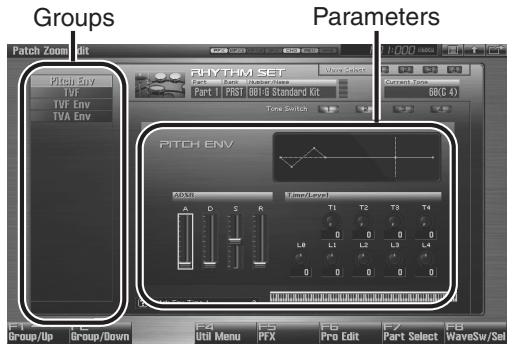
text_image
Groups Pitch Zoom Edit Pitch Env TVF TVF Env TVA Env Rhythm Set Wave Select Part 1 Part 2 Number/Units Part 1 PIST BBI-B Standard Kit BBC 4) Tone Switch PITCH ENV ADSN A D S R Wave/Temp T1 T2 T3 T4 0 0 0 L0 L1 L2 L3 L4 0 0 0 0 Group/Up Group/Down F4 F5 F6 F7 F8 Ubl Menu PTX Pro Edit Part Select WaveSw/SatF-key operations in the Patch Zoom Edit screen
| F-key | Explanation | Page | |
| F1 Group/Up | Moves the edit group tab upward. | - | |
| F2 Group/Down | Moves the edit group tab downward. | - | |
| F4 Util Menu | Rhythm Set Initialize | Initializes the settings of the currently selected rhythm set. | p. 115 |
| Rhythm Key Initialize | Initializes the settings of the currently selected rhythm key. | p. 115 | |
| Rhythm Tone Copy | Copies settings from a desired rhythm set to the currently selected rhythm set. | p. 115 | |
| F5 PFX | Accesses the PFX (Patch Multi-effect) editing screen. | p. 157 | |
| F6 Pro Edit | Accesses the Patch Pro Edit screen, where you can edit all of the parameters. | p. 114 | |
| F7 Part Select | Selects the part to be edited. | - | |
| F8 Wave Sw/Sel | Selects the tones that will sound. | p. 113 | |
- The parameters are organized into several editing groups. Press [F1 (Up)] or [F2 (Down)] to select the tab for the editing group that contains the parameter you wish to edit.
TIP
For details on each parameter, refer to the following pages.
| Parameter name | Page |
| Pitch Envelope | p. 121 |
| TVF | p. 122 |
| TVF Envelope | p. 124 |
| TVA Envelope | p. 125 |
• To change the part that you want to edit
Press [F7 (Part Select)].
-
Press [CURSOR] button to move the cursor to the parameter you wish to modify.
-
Press [F8 (Wave Sw/Sel)] to select the wave that you want to edit.
The Wave Switch/Select window will appears.

text_image
Wave Switch/Select (F1 F2 F3 F4 F5 F6 Select 1 F7 Select 2 F8 Select 3 F9 Select 4 Sw 1 Sw 2 Sw 3 Sw 4 Select 1 Select 2 Select 3 Select 4 (Push EXIT to close)Press any one of the [F5 (Select 1)]–[F8 (Select 4)] buttons to select the wave that you want to edit.
- Simultaneously editing the same parameter of multiple waves
To select the waves you want to edit at the same time, simultaneously press two or more of the [F5 (Select 1)]-[F8 (Select 4)] buttons.
• To switch a wave on/off
Press a [F1 (Sw 1)]–[F4 (Sw 4)] button to switch the corresponding wave on/off.
TIP
You can also use the pads to select waves and switch them on/off. p. 197
-
When you have made your selection, press [EXIT].
-
Turn the VALUE dial, or Press [INC] [DEC] to set a value.
If you've selected several waves for editing, their values will change while maintaining the difference between them.
-
Repeat steps 3–7 to set each parameter you want to edit.
-
If you wish to save the changes you've made, press [WRITE] to perform the Save operation (p. 116). If you do not wish to save changes, press [EXIT] to return to the Single Play screen.
If you return to the Single Play screen without saving, the “√” symbol will be displayed at the right of the rhythm set name, indicating that the rhythm set settings have been edited.
NOTE
The settings you edit are temporary, and will be lost if you turn off the power, switch the sound generator mode, or select a different sound.
Editing All Parameters (Patch Pro Edit)
The Patch Pro Edit screen allows you to edit all parameters of a patch.
- Select the rhythm set whose settings you want to edit (p. 52).

If you want to create a rhythm set from scratch (rather than starting from an existing rhythm set), execute the Initialize operation (p. 115).
- Press [PATCH] twice.
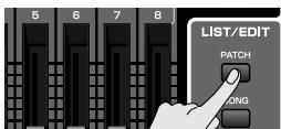
The Patch Pro Edit screen appears.
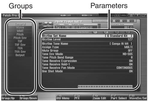
text_image
Groups RHYTHM SET Patch Pro Bkt General Wave WM1 Pitch Pitch Env TVF TVF Env TVA TVA Env Output Rhythm Set Name [ G Standard Kit ] Rhythm Level 127 Rhythm Tone Name [ Conpa Hi Mt ] Assign Type MULTI Mate Group OFF Tone Env Mode NO-SUS Tone Pitch Bend Range ON Tone Receive Expression ON Tone Receive Hold-1 ON Tone Receive Pan Mode CONTINUOUS One Shot Mode ON Parameters F4 F5 F6 F7 F8 Util Menu PTX Zoom Edit Part Select WaveSw/SellF-key operations in the Patch Pro Edit screen
| F-key | Explanation | Page | |
| F1 Group/Up | Moves the edit group tab upward. | - | |
| F2 Group/Down | Moves the edit group tab downward. | - | |
| F3 Set Stereo | This is shown if you're editing the WAVE group. It recalls the right wave (R) from the left wave (L) of a stereo wave. | p. 119 | |
| F4 Util Menu | Rhythm Set Initialize | Initializes the settings of the currently selected rhythm set. | p. 115 |
| Rhythm Key Initialize | Initializes the settings of the currently selected rhythm key. | p. 115 | |
| Rhythm Tone Copy | Copies the settings of a desired rhythm set to the currently selected rhythm set. | p. 115 | |
| F5 PFX | Accesses the PFX (Patch Multi-effect) editing screen. | p. 157 | |
| F6 Zoom Edit | Accesses the Patch Zoom Edit screen, where you can edit the most important parameters. | p. 112 | |
| F7 Part Select | Selects the part to be edited. | - | |
| F8 Wave Sw/Sel | Selects the tones that will sound. | p. 113 | |
- The parameters are organized into several editing groups. Press [F1 (Up)] or [F2 (Down)] to select the tab for the editing group that contains the parameter you wish to edit.
See “Functions of Rhythm Set Parameters” (p. 117) for each parameter’s functions.
- To change the part that you want to edit Press [F7 (Part Select)].
-
Use ▲ or ▼ to move the cursor to the parameter you wish to modify.
-
Press [F8 (Wave Sw/Sel)] to select the wave that you want to edit.
The Wave Switch/Select window will appears.

text_image
Wave Switch/Select (F1 F2 F3 F4 F5 F6 Select 1 F7 Select 2 Select 3 F8 Select 4 Sw 1 Sw 2 Sw 3 Sw 4 Select 1 Select 2 Select 3 Select 4 (Push EXIT) to close)Press any one of the [F5 (Select 1)]–[F8 (Select 4)] buttons to select the wave that you want to edit.
- Simultaneously editing the same parameter of multiple waves
To select the waves you want to edit at the same time, simultaneously press two or more of the [F5 (Select 1)]-[F8 (Select 4)] buttons.
• To switch a wave on/off
Press a [F1 (Sw 1)]–[F4 (Sw 4)] button to switch the corresponding wave on/off.

You can also use the pads to select waves and switch them on/off. p. 197
- When you have made your selection, press [EXIT].
- Turn the VALUE dial, or Press [INC] [DEC] to set a value.
- Repeat steps 3–7 to set each parameter you want to edit.
- If you wish to save the changes you've made, press [WRITE] to perform the Save operation (p. 116). If you do not wish to save changes, press [EXIT] to return to the Single Play screen.
If you return to the Single Play screen without saving, the “√” symbol will be displayed at the right of the rhythm set name, indicating that the rhythm set settings have been edited.

The settings you edit are temporary, and will be lost if you turn off the power, switch the sound generator mode, or select a different sound.
Initializing Rhythm Set/Key Settings (Rhythm Set Initialize/Rhythm Key Initialize)
"Initialize" means to return the settings of the currently selected sound to a standard set of values or to the factory settings.
NOTE
The Initialize operation will affect only the currently selected sound. If you wish to restore all of the Fantom's settings to their factory values, perform a Factory Reset (p. 284).
-
Select the rhythm set that you want to initialize (p. 52).
-
Press [PATCH].
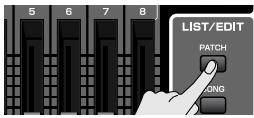
- Press [F4 (Util Menu)].
The Rhythm Set Utility Menu window appears.
- Press ▲ or ▼ to choose what you want to initialize, and then press [F8 (Select)].
• Rhythm Set Initialize:
All keys of the rhythm set will be initialized. (This is the same as the rhythm set initialize procedure described above.)
• Rhythm Key Initialize:
One key will be initialized.
- Press [F8 (Select)].
To cancel, press [F7 (Cancel)].
A message will ask you for confirmation.
- Press [F7 (OK)] to execute.
To cancel, press [F8 (EXIT)].
Copying Rhythm Tone Settings (Rhythm Tone Copy)
This operation copies the settings of any desired rhythm set to the currently selected rhythm set. You can use this feature to make the editing process faster and easier.
- Select the copy-destination Rhythm set (p. 52).
- Press [PATCH].
- Press [F4 (Util Menu)].
The Rhythm Utility Menu window appears.
- Press ▲ or ▼ to choose "Rhythm Tone Copy," and then press [F8 (Select)].
To cancel, press [F7 (Cancel)].
The Rhythm Tone Copy window appears.
- Using [CURSOR] to move the cursor, select the "Source (copy-source)" bank and number, and the rhythm tone.
- Turn the VALUE dial or use [INC] [DEC] to make the setting.
- Using [CURSOR] to move the cursor, select the "Destination (copy-destination)" rhythm tone number.
- Turn the VALUE dial or use [INC] [DEC] to make the setting.
- Press [F8 (Execute)].
A message will ask for confirmation.
- Press [F7 (OK)] to return to the Rhythm Edit screen.
To cancel, press [F8 (EXIT)].
The Compare Function
For the Rhythm Tone Copy operations, you can use the Compare function.
If you want to play the copy-source patch, press [F6 (Compare)].
NOTE
The rhythm set auditioned using the Compare function may sound slightly different than when it is played normally.
Cautions When Selecting a Waveform
The sounds of the Fantom-G are based on complex PCM waveforms, and if you attempt to make settings that are contrary to the type of the original waveform, the results will not be as you expect.
The internal waveforms of the Fantom-G fall into the following two groups.
One-shot:
These waveforms contain sounds that have short decays. A one-shot waveform records the initial rise and fall of the sound. Some of the Fantom-G's one-shot waveforms are sounds that are complete in themselves, such as percussive instrument sounds. The Fantom-G also contains many other one-shot waveforms that are elements of other sounds. These include attack components such as piano-hammer sounds and guitar fret noises.
Looped:
These waveforms include sounds with long decays as well as sustained sounds. Loop waveforms repeatedly play back (loop) the portion of the waveform after the sound has reached a relatively steady state. The Fantom-G's looped waveforms also include components of other sounds, such as pianostring resonant vibrations and the hollow sounds of brass instruments.
Cautions When Using a One-shot Waveform
It is not possible to use the envelope to modify a one-shot waveform to create a decay that is longer than the original waveform, or to turn it into a sustaining sound. If you were to program such an envelope, you would be attempting to shape a portion of the sound that simply doesn't exist, and the envelope would have no effect.
Cautions When Using a Loop Waveform
With many acoustic instruments such as piano and sax, extreme timbral changes occur during the first few moments of each note. This initial attack is what defines much of the instrument's character. For such waveforms, it is best to use the complex tonal changes of the attack portion of the waveform just as they are, and to use the envelope only to modify the decay portion. If you attempt to use the envelope to modify the attack portion as well, the characteristics of the original waveform may prevent you from getting the sound that you intend.
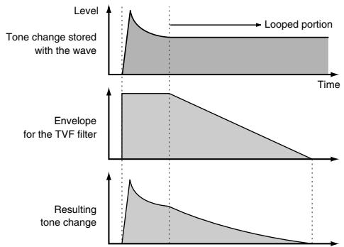
area
| Time Segment | Value | | ------------------------- | ----- | | Level | 0 | | Looped portion | 1 | | Envelope for the TVF filter | 0 | | Resulting tone change | 1 |Saving Rhythm Sets You've Created (Write)
The settings you edit are temporary, and will be lost if you turn off the power, switch the sound generator mode, or select a different sound. If you want to keep the modified sound, you must save it in the user bank.
When you edit the rhythm set settings, the “√” symbol will appear in the Single Play screen. When you save the rhythm set, the “√” symbol will disappear.
NOTE
When you perform the save procedure, the data that previously occupied the save destination will be lost.
- Make sure that the Rhythm Set you wish to save is selected.
- Press [WRITE].
The WRITE MENU window appears.
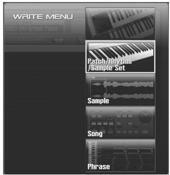
text_image
WRITE MENU RGB1-CM Grand Piano Tone Switch Patch/Phrytirm /Sample Set Sample Song Phrase- Select "Patch / Rhythm / Sample Set."
Press ▲ or ▼ to select "Patch / Rhythm / Sample Set," and then press [F8 (Select)].
The Rhythm Set Name window appears.
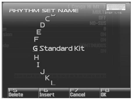
text_image
RHYTHM SET NAME C D E F G Standard Kit H I J K L F5 Delete F6 Insert F7 Cancel F8 OK OFF NO-SUS ON CONTINUOUS ON MULT STEP 1/16- Assign a name to the rhythm set.
cf.
For details on assigning names, refer to “Assigning a Name” (p. 42).
- When you have finished inputting the name, press [F8 (OK)].
A screen will appear, allowing you to select the write-destination rhythm set.
- Turn the VALUE dial or use [INC] [DEC] to select the rhythm set number.
TIP
By pressing [F6 (Compare)] you can check the save-destination Rhythm set (Compare function).
- Press [F8 (Write)].
A message will ask you for confirmation.
NOTE
Never switch off the Fantom-G while data is being saved.
- Press [F7 (OK)] to execute the save operation.
To cancel, press [F8 (EXIT)].
Auditioning the Save-Destination Rhythm Set (Compare)
Before you save a rhythm set, you can audition the rhythm set which currently occupies the save destination to make sure that it is one you don't mind overwriting. This can help prevent important rhythm sets from being accidentally overwritten and lost.
- Follow the procedure in "Saving Rhythm Sets You've Created (Write)" through step 5 to select the save destination.
- Press [F6 (Compare)] to turn on.
The Rhythm Compare window appears, making it possible to sound the currently selected save destination rhythm set.
- Play the keyboard or pad to sound the save destination rhythm set, then check whether you really want to overwrite it.
NOTE
The rhythm set auditioned using the Compare function may sound slightly different than when it is played normally.
- If you wish to change the save destination, re-specify the save-destination rhythm set by turning the VALUE dial.
- Press [F8 (Write)].
A message will ask you for confirmation.
- Press [F7 (OK)] once again to execute the Save operation.
Functions of Rhythm Set Parameters
This section explains the functions the different rhythm set parameters have, as well as the composition of these parameters. If a number is displayed for the parameter name, (1, 2, 3, 4), you can use the realtime controller knob of the corresponding number (the left most knob is number 1, the right most knob is number 4) to set the value.
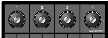
text_image
1 2 3 4 MAGIC CTRLMaking Settings Common to the Entire Rhythm Set (General)
NOTE
Rhythm Set Name and Rhythm Level applies to the entire rhythm set; the other parameters are set individually for each rhythm tone.
Rhythm Set Name
Specifies the name of the rhythm set.
By pressing [ENTER], you can assign a name to the rhythm set.
Value: space, A-Z, a-z, 0-9,!" # \$ % & ' ( ) * + ,-. / : ;<=> ? @ [ \ ] ^ _ ` { | }
cf.
For details on entering a name, refer to “Assigning a Name” (p. 42).
Rhythm Level (Rhythm Set Level)
Sets the volume of the rhythm set.
Value: 0–127
TIP
The volume levels of the tones from which the rhythm set is composed is set with the Tone Level parameter (p. 124). The volume levels of the Waves from which the rhythm tone is composed is set with the Wave Level parameter (p. 120).
Rhythm Tone Name
You can assign a name of up to 12 characters to the rhythm tone.
By pressing [ENTER], you can assign a name to the rhythm tone.
Value: space, A-Z, a-z, 0-9,!" # \$ % & ' ( ) * + , - . / : ; <= > ? @ [ \ ] ^ _ ` { | }
cf.
For details on assigning names, refer to “Assigning a Name” (p. 42)
Assign Type
Assign Type sets the way sounds are played when the same key is pressed a number of times.
Value
MULTI: Layer the sound of the same keys. Even with continuous sounds where the sound plays for an extended time, such as with crash cymbals, the sounds are layered, without previously played sounds being eliminated.
SINGLE: Only one sound can be played at a time when the same key is pressed. With continuous sounds where the sound plays for an extended time, the previous sound is stopped when the following sound is played.
Mute Group
On an actual acoustic drum set, an open hi-hat and a closed hi-hat sound can never occur simultaneously. To reproduce the reality of this situation, you can set up a Mute Group.
The Mute Group function allows you to designate two or more rhythm tones that are not allowed to sound simultaneously. Up to 31 Mute Groups can be used. rhythm tones that are not belong to any such group should be set to “OFF.”
Value: OFF, 1–31
Tone Env Mode (Rhythm Tone Envelope Mode)
When a loop waveform (p. 116) is selected, the sound will normally continue as long as the key is pressed. If you want the sound to decay naturally even if the key remains pressed, set this to “NO-SUS.”
Value: NO-SUS, SUSTAIN
NOTE
If a one-shot type Wave (p. 116) is selected, it will not sustain even if this parameter is set to "SUSTAIN."
Tone Pitch Bend Range
(Rhythm Tone Pitch Bend Range)
Specifies the amount of pitch change in semitones (4 octaves) that will occur when the Pitch Bend Lever is moved. The amount of change when the lever is tilted is set to the same value for both left and right sides.
Value: 0–48
Tone Receive Expression (Rhythm Tone Receive Expression Switch)
For each rhythm tone, specify whether MIDI Expression messages will be received (ON), or not (OFF).
Value: OFF, ON
Tone Receive Hold-1
(Rhythm Tone Receive Hold-1 Switch)
For each rhythm tone, specify whether MIDI Hold-1 messages will be received (ON), or not (OFF).
Value: OFF, ON
NOTE
If "NO-SUS" is selected for Env Mode parameter (p. 118), this setting will have no effect.
Tone Receive Pan Mode
(Rhythm Tone Receive Pan Mode)
For each rhythm tone, specify how pan messages will be received.
Value
CONTINUOUS: Whenever Pan messages are received, the stereo position of the tone will be changed.
KEY-ON: The pan of the tone will be changed only when the next note is played. If a pan message is received while a note is sounding, the panning will not change until the next key is pressed.
NOTE
If “PFX (Patch Multi-Effects)” (p. 157) is on, the Tone Receive Pan Mode setting is ignored.
NOTE
The channels cannot be set so as not to receive Pan messages.
One Shot Mode
The sound will play back until the end of the waveform (or the end of the envelope, whichever comes first). The result will be the same as when the envelope's Tone Env Mode parameter (p. 118) is set to NO-SUS. If you have set Wave Group (p. 119) to Sample, the loop setting will be forced to ONE SHOT.
Value: OFF, ON
Modifying Waveforms (Wave)
MEMO
With rhythm tones, sounds are created by combining up to four Waves (eight for stereo).
Tips on Creating a Rhythm Tone
The Waves for the bass drum, snare, hi-hat, toms, and other percussion instruments are each assigned to one rhythm tone. When adding 3D effects to the sound, make the Pan settings for each rhythm tone individually.
Wave Group
Select the groups containing the Waves comprising the rhythm tone.
Value
INT: Waveforms stored in internal
SAMP: Sample waveforms
Wave Number L (Mono) Wave Number R
This selects the Waves comprising the rhythm tone. Along with the Wave number, the Wave name appears at the lower part of the display.
When in monaural mode, only the left side (L) is specified. When in stereo, the right side (R) is also specified.
Value: OFF, 1– (The upper limit will depend on the wave group.)
MEMO
If you want to select a left/right pair of Waves, select the left (L) Wave number and then press [F3 (Set Stereo)]; the right (R) (Wave) will be recalled.
* When using a sample in stereo, you must specify the same number for L and R.
Wave Gain
Sets the gain (amplification) of the waveform. The value changes in 6 dB (decibel) steps—an increase of 6 dB doubles the waveform's gain.
Value: -6, 0, +6, +12
Wave Tempo Sync
When you wish to synchronize a Phrase Loop to the clock (tempo), set this to "ON." This is valid only when selected as the sample for a wave.
Value: OFF, ON
NOTE
- If a sample is selected for a tone, you must first set the BPM (tempo) parameter of the sample.
- If a sample is selected for a tone, Wave Tempo Sync will require twice the normal number of voices.
Phrase Loop
Phrase loop refers to the repeated playback of a phrase that's been pulled out of a song (e.g., by using a sampler). One technique involving the use of Phrase Loops is the excerpting of a Phrase from a pre-existing song in a certain genre, for example dance music, and then creating a new song with that Phrase used as the basic motif. This is referred to as "Break Beats."
Realtime Time Stretch
If the wave group is "SAMP," and the Wave Tempo Sync parameter is turned "ON," you can vary the playback speed of the waveform without affecting the pitch.
Wave FXM Switch
This sets whether FXM will be used (ON) or not (OFF).
Value: OFF, ON
FXM
FXM (Frequency Cross Modulation) uses a specified waveform to apply frequency modulation to the currently selected waveform, creating complex overtones. This is useful for creating dramatic sounds or sound effects.
Wave FXM Color
Specifies how FXM will perform frequency modulation. Higher settings result in a grainier sound, while lower settings result in a more metallic sound.
Value: 1–4
Wave FXM Depth
Specifies the depth of the modulation produced by FXM.
Value: 0–16
NOTE
When the Tempo Sync parameter is set to "ON," settings related to Pitch (p. 121) and FXM (p. 120) are disabled.
Changing How a Rhythm Tone Is Sounded (WMT)
The WMT (Wave Mix Table) uses key velocity to control the four waveforms assigned to the rhythm tone.
Wave Coarse Tune
Adjusts the pitch of the waveform's sound up or down in semitone steps (+/-4 octaves).
Value: -48- +48
TIP
The Coarse Tune of the entire rhythm tone is set by the Tone Coarse parameter (p. 121).
Wave Fine Tune
Adjusts the pitch of the waveform's sound up or down in 1-cent steps (+/-50 cents).
Value: -50- +50
MEMO
One cent is 1/100th of a semitone.
TIP
The Fine Tune of the entire rhythm tone is set by the Tone Fine Tune parameter (p. 121).
Wave Level
You can set the volume of the waveform.
Value: 0–127
TIP
The volume level of each rhythm tone is set with the Tone Level parameter; the volume levels of the entire rhythm set is set with the Rhythm Level parameter (p. 117).
Wave Pan
This specifies the pan of the waveform. "L64" is far left, "0" is center, and "63R" is far right.
Value: L63-0-63R
Wave Random Pan Switch
Use this setting to cause the waveform's panning to change randomly each time a key is pressed (ON) or not (OFF).
Value: OFF, ON
* The range of the panning change is set by the Rnd Pan Depth parameter (p. 124).
Wave Alternate Pan Switch
This setting causes panning of the waveform to be alternated between left and right each time a key is pressed. Set Alternate Pan Switch to “ON” to pan the Wave according to the Alter Pan Depth parameter (p. 125) settings, or to “REV” when you want the panning reversed. If you do not want the panning to change each time a key is pressed, set this to “OFF.”
Range: OFF, ON, REV
WMT Velocity Control (WMT Velocity Control Switch)
WMT Velocity Control determines whether a different rhythm tone is played (ON) or not (OFF) depending on the force with which the key is played (velocity).
When set to "RND," the rhythm set's constituent rhythm tones will sound randomly, regardless of any Velocity messages.
Value: OFF, ON, RANDOM
Velocity Fade Width Lower
This determines what will happen to the tone's level when the tone is played at a velocity lower than its specified velocity range. Higher settings produce a more gradual change in volume. If you want notes played outside the specified key velocity range to not be sounded at all, set this to "0."
Value: 0–127
Velocity Range Lower
This sets the lowest velocity at which the waveform will sound. Make these settings when you want different waveforms to sound in response to notes played at different strengths.
Value: 1-UPPER
Velocity Range Upper
This sets the highest velocity at which the waveform will sound. Make these settings when you want different waveforms to sound in response to notes played at different strengths.
Value: LOWER-127
NOTE
If you attempt to set the Lower velocity limit above the Upper, or the Upper below the Lower, the other value will automatically be adjusted to the same setting.
Velocity Fade Width Upper
This determines what will happen to the tone's level when the tone is played at a velocity greater than its specified velocity range. Higher settings produce a more gradual change in volume. If you want notes played outside the specified key velocity range to not be sounded at all, set this to "0."
Value: 0–127
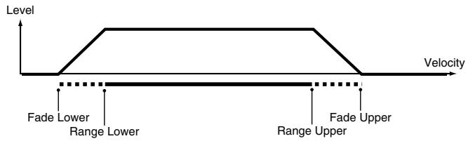
text_image
Level Velocity Fade Lower Range Lower Range Upper Fade UpperModifying Pitch (Pitch/Pitch Env)
Pitch
Tone Coarse Tune (Rhythm Tone Coarse Tune)
Selects the pitch at which a rhythm tone sounds.
Value: C-1–G9
TIP
Set the coarse tuning for Waves comprising the rhythm tones with the Wave Coarse Tune parameter (p. 120).
Tone Fine Tune (Rhythm Tone Fine Tune)
Adjusts the pitch of the rhythm tone's sound up or down in 1-cent steps (+/-50 cents).
Value: -50- +50
MEMO
One cent is 1/100th of a semitone.
TIP
Set the fine tuning for Waves comprising the rhythm tones with the Wave Fine Tune parameter (p. 120).
Tone Random Pitch Depth
This specifies the width of random pitch deviation that will occur each time a key is pressed. If you do not want the pitch to change randomly, set this to “0.” These values are in units of cents (1/100th of a semitone).
Value: 0, 1, 2, 3, 4, 5, 6, 7, 8, 9, 10, 20, 30, 40, 50, 60, 70, 80, 90, 100, 200, 300, 400, 500, 600, 700, 800, 900, 1000, 1100, 1200
Pitch Env (Pitch Envelope)
Pitch Env Depth
Adjusts the effect of the Pitch Envelope. Higher settings will cause the pitch envelope to produce greater change. Negative (-) settings will invert the shape of the envelope.
Value: -12- +12
Pitch Env Velocity Sens
Keyboard playing dynamics can be used to control the depth of the pitch envelope. If you want the pitch envelope to have more effect for strongly played notes, set this parameter to a positive (+) value. If you want the pitch envelope to have less effect for strongly played notes, set this to a negative (-) value.
Value: -63- +63
Pitch Env Time 1 Velocity Sens
This allows keyboard dynamics to affect the Time 1 of the Pitch envelope. If you want Time 1 to be speeded up for strongly played notes, set this parameter to a positive (+) value. If you want it to be slowed down, set this to a negative (-) value.
Value: -63- +63
Pitch Env Time 4 Velocity Sens
Use this parameter when you want key release speed to affect the Time 4 value of the pitch envelope. If you want Time 4 to be speeded up for quickly released notes, set this parameter to a positive (+) value. If you want it to be slowed down, set this to a negative (-) value.
Value: -63- +63
Pitch Env Time 1-4
Specify the pitch envelope times (Time 1–Time 4). Higher settings will result in a longer time until the next pitch is reached. (For example, Time 2 is the time over which the pitch changes from Level 1 to Level 2.)
Value: 0–127
Pitch Env Level 0-4
Specify the pitch envelope levels (Level 0–Level 4). It determines how much the pitch changes from the reference pitch (the value set with Coarse Tune or Fine Tune on the Pitch screen) at each point. Positive (+) settings will cause the pitch to be higher than the standard pitch, and negative (-) settings will cause it to be lower.
Value: -63- +63
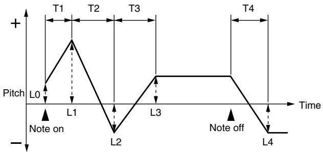
line
| Time | Pitch | Annotation | |------|-------|----------------| | T1 | + | Pitch L0 | | T2 | + | Pitch L1 | | T3 | + | Pitch L2 | | T4 | + | Pitch L3 | | L0 | - | Note on | | L1 | - | Note on | | L2 | - | Note on | | L3 | + | Note off | | L4 | - | Note off |T: Time L: Level
Modifying the Brightness of a Sound with a Filter (TVF/TVF Env)
TVF
Filter Type
Selects the type of filter. A filter cuts or boosts a specific frequency region to change a sound's brightness, thickness, or other qualities.
Value
OFF: No filter is used.
LPF: Low Pass Filter. This reduces the volume of all frequencies above the cutoff frequency (Cutoff Freq) in order to round off, or un-brighten the sound. This is the most common filter used in synthesizers.
BPF: Band Pass Filter. This leaves only the frequencies in the region of the cutoff frequency (Cutoff Frequency), and cuts the rest. This can be useful when creating distinctive sounds.
HPF: High Pass Filter. This cuts the frequencies in the region below the cutoff frequency (Cutoff Frequency). This is suitable for creating percussive sounds emphasizing their higher ones.
PKG: Peaking Filter. This emphasizes the frequencies in the region of the cutoff frequency (Cutoff Frequency). You can use this to create wah-wah effects by employing an LFO to change the cutoff frequency cyclically.
LPF2: Low Pass Filter 2. Although frequency components above the Cutoff frequency (Cutoff Frequency) are cut, the sensitivity of this filter is half that of the LPF. This makes it a comparatively warmer low pass filter. This filter is good for use with simulated instrument sounds such as the acoustic piano.
LPF3: Low Pass Filter 3. Although frequency components above the Cutoff frequency (Cutoff Frequency) are cut, the sensitivity of this filter changes according to the Cutoff frequency. While this filter is also good for use with simulated acoustic instrument sounds, the nuance it exhibits differs from that of the LPF2, even with the same TVF Envelope settings.
NOTE
If you set "LPF2" or "LPF3," the setting for the Resonance parameter will be ignored.
Cutoff Frequency
Selects the frequency at which the filter begins to have an effect on the waveform's frequency components.
Value: 0–127
With “LPF/LPF2/LPF3” selected for the Filter Type parameter, lower cutoff frequency settings reduce a tone’s upper harmonics for a more rounded, warmer sound. Higher settings make it sound brighter.
If “BPF” is selected, harmonic components will change depending on the TVF Cutoff Frequency setting. This can be useful when creating distinctive sounds.
With "HPF" selected, higher Cutoff Frequency settings will reduce lower harmonics to emphasize just the brighter components of the sound.
With “PKG” selected, the harmonics to be emphasized will vary depending on Cutoff Frequency setting.
Resonance
Emphasizes the portion of the sound in the region of the cutoff frequency, adding character to the sound. Excessively high settings can produce oscillation, causing the sound to distort.
[Non-Text]
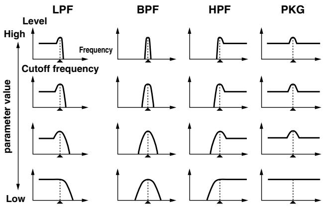
line
| Method | Level | Cutoff frequency | parameter value | |--------|-------|------------------|-----------------| | LPF | High | Low | Low | | BPF | High | Low | Low | | HPF | High | Low | Low | | PKG | High | Low | Low |Cutoff Velocity Curve
Selects one of the following seven curves that determine how keyboard playing dynamics (velocity) influence the cutoff frequency. Set this to “FIXED” if you don’t want the Cutoff frequency to be affected by the keyboard velocity.
Value: FIXED, 1–7

text_image
1 2 3 4 5 6 7Cutoff Velocity Sens
Use this parameter when changing the cutoff frequency to be applied as a result of changes in playing velocity. If you want strongly played notes to raise the cutoff frequency, set this parameter to positive (+) settings. If you want strongly played notes to lower the cutoff frequency, use negative (-) settings.
Value: -63- +63
Resonance Velocity Sens
This allows keyboard velocity to modify the amount of Resonance. If you want strongly played notes to have a greater Resonance effect, set this parameter to positive (+) settings. If you want strongly played notes to have less Resonance, use negative (-) settings.
Value: -63- +63
TVF Env Velocity Curve
Selects one of the following 7 curves that will determine how keyboard playing dynamics will affect the TVF envelope. Set this to "FIXED" if you don't want the TVF Envelope to be affected by the keyboard velocity.
Value: FIXED, 1–7

text_image
1 2 3 4 5 6 7TVF Env Velocity Sens
Specifies how keyboard playing dynamics will affect the depth of the TVF envelope. Positive (+) settings will cause the TVF envelope to have a greater effect for strongly played notes, and negative (-) settings will cause the effect to be less.
Value: -63- +63
TVF Env Time 1 Velocity Sens
This allows keyboard dynamics to affect the Time 1 of the TVF envelope. If you want Time 1 to be speeded up for strongly played notes, set this parameter to a positive (+) value. If you want it to be slowed down, set this to a negative (-) value.
Value: -63- +63
TVF Env Time 4 Velocity Sens
The parameter to use when you want key release speed to control the Time 4 value of the TVF envelope. If you want Time 4 to be speeded up for quickly released notes, set this parameter to a positive (+) value. If you want it to be slowed down, set this to a negative (-) value.
Value: -63- +63
TVF Env
TVF Env Depth
Specifies the depth of the TVF envelope. Higher settings will cause the TVF envelope to produce greater change. Negative (-) settings will invert the shape of the envelope.
Value: -63- +63
Specify the TVF envelope times (Time 1– Time 4). Higher settings will lengthen the time until the next cutoff frequency level is reached. (For example, Time 2 is the time over which Level 1 will change to Level 2.)
Value: 0–127
TVF Env Level 0-4 (TVF Envelope Level 0-4)
Specify the TVF envelope levels (Level 0–Level 4). These settings specify how the cutoff frequency will change at each point, relative to the standard cutoff frequency (the cutoff frequency value specified in the TVF screen).
Value: 0–127
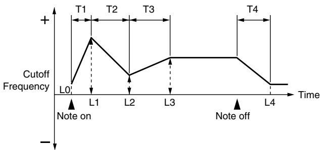
line
| Time | Cutoff Frequency | |------|------------------| | L0 | 0 | | L1 | Peak (T1) | | L2 | Low | | L3 | High | | L4 | Low |T: Time L: Level
Adjusting the Volume (TVA/TVA Env)
TVA
Tone Level (Rhythm Tone level)
Sets the volume of the rhythm tone. Use this parameter to adjust the volume balance between rhythm tones.
Value: 0–127
TIP
The volume levels of the Waves from which the rhythm tone is composed is set with the WMT1–4 Wave Level parameter (p. 120).
Level Velocity Curve
You can select from seven curves that determine how keyboard playing strength will affect the volume. If you do not want the volume of the rhythm tone to be affected by the force with which you press the key, select "FIXED."
Value: FIXED, 1–7

text_image
1 2 3 4 5 6 7Level Velocity Sens
Set this when you want the volume of the rhythm tone to change depending on the force with which you press the keys. Set this to a positive (+) value to have the changes in rhythm tone volume increase the more forcefully the keys are played; to make the tone play more softly as you play harder, set this to a negative (-) value.
Value: -63- +63
Tone Pan (Rhythm Tone Pan)
Sets the pan for the rhythm tone. "L64" is far left, "0" is center, and "63R" is far right.
Value: L64-0-63R
TIP
Set the Pan for Waves comprising the rhythm tones with the Wave Pan parameter (p. 120).
Random Pan Depth
Use this parameter when you want the stereo location to change randomly each time you press a key. Higher settings will produce a greater amount of change.
Value: 0–63
NOTE
This will affect only waves whose Wave Rnd Pan Sw parameter (p. 120) is ON.
Alternate Pan Depth
This setting causes panning to be alternated between left and right each time a key is pressed. Higher settings will produce a greater amount of change. "L" or "R" settings will reverse the order in which the pan will alternate between left and right. For example if two rhythm tones are set to "L" and "R" respectively, the panning of the two rhythm tones will alternate each time they are played.
Value: L63-0-63R
NOTE
This will affect only waves whose Wave Alter Pan Sw parameter (p. 120) is ON or REV.
Relative Level
Corrects for the volume of the rhythm tone.
This parameter is set by the key-based controller system exclusive message. Normally, you should leave it set to 0.
Value: -64- +63
NOTE
If the rhythm tone level is set to 127, the volume will not increase beyond that point.
TVA Env
TVA Env Time 1 Velocity Sens
This allows keyboard dynamics to affect the Time 1 of the TVA envelope. If you want Time 1 to be speeded up for strongly played notes, set this parameter to a positive (+) value. If you want it to be slowed down, set this to a negative (-) value.
Value: -63- +63
TVA Env Time 4 Velocity Sens
The parameter to use when you want key release speed to control the Time 4 value of the TVA envelope. If you want Time 4 to be speeded up for quickly released notes, set this parameter to a positive (+) value. If you want it to be slowed down, set this to a negative (-) value.
Value: -63- +63
TVA Env Time 1-4
Specify the TVA envelope times (Time 1– Time 4). Higher settings will lengthen the time until the next volume level is reached. (For example, Time 2 is the time over which Level 1 will change to Level 2.)
Value: 0–127
TVA Env Level 1-3
Specify the TVA envelope levels (Level 1–Level 3). These settings specify how the volume will change at each point, relative to the standard volume (the Rhythm Tone Level value specified in the TVA screen).
Value: 0–127
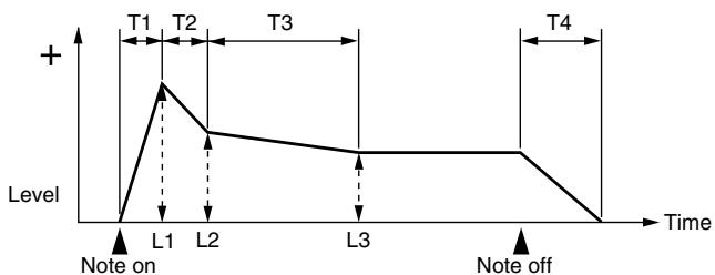
line
| Time Point | Level | | ---------- | ----- | | L1 | Peak | | L2 | Decreasing from peak | | L3 | Decreasing from peak | | Note on | 0 | | Note off | 0 |T: Time L: Level
Output Settings (Output)
Tone Output Assign
Specifies how the direct sound of each tone will be output.
Value:
PFX: Output through patch multi-effects.
DRY: Output without passing through patch multi-effects.
Tone Output Level
Specifies the signal level of each tone.
Value: 0–127
Tone Chorus Send Level
Specifies the level of the signal sent to the chorus for each tone.
Value: 0–127
Tone Reverb Send Level
Specifies the level of the signal sent to the reverb for each tone.
Value: 0–127
Setting Effects for a Rhythm Set (PFX)
You can press the [F5 (PFX)] button to access the PFX (Patch Multi-effect) editing screen (p. 157).
cf.
For details regarding effect settings, refer to the pages shown below.
• “Making Effect Settings” (p. 151)
- “Making Patch Multi-Effects Settings (PFX)” (p. 157)
With the Fantom-G, you have total control over a wide variety of settings. Each item that can be set is known as a parameter. When you change the values of parameters, you are doing what is referred to as Editing. This chapter explains the procedures used in creating sample sets, and the functions of the sample set parameters.
How to make Sample Set settings
On the Fantom-G, a waveform (wave) obtained by audio recording or sampling is called a “sample.” A sample set consists of sixteen samples handled as a set. You can specify how the samples will play when you press a pad or note on the keyboard.
Here's how to create a new sample set by starting with one of the provided sample sets.
Editing a Sample Set Quickly (Patch Zoom Edit)
The Patch Zoom Edit screen lets you edit the most important parameters. If you want to have access to all parameters, use the Patch Pro Edit screen (p. 127).
- Select the sample set whose settings you want to edit (p. 53).
- Press [PATCH].
The Patch Zoom Edit screen appears.
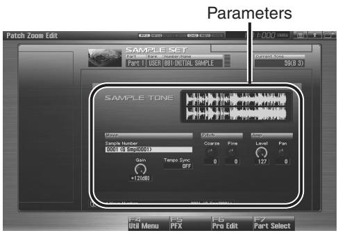
text_image
Parameters Patch Zoom Edit SAMPLE SET Part 1: Sample Number Part 1: USB (001:INITIAL SAMPLE) Current Tools 50(8.3) SAMPLE TONE Sample Number 0001 (G Smp0001) Gain +12dB Patch Colorate Fine Level Pan 0 0 127 0 Tempo Sync OFF F4 F5 F6 F7 Util Menu PFX Pro Edit Part SelectF-key operations in the Patch Zoom Edit screen
| F-key | Explanation | Page | |
| F4Util Menu | SampleSetInitialize | Initializes the settings of the currently selected sample set. | p. 127 |
| F5PFX | Accesses the PFX (Patch Multi-effect) editing screen. | p. 157 | |
| F6Pro Edit | Accesses the Patch Pro Edit screen, where you can edit all of the parameters. | p. 127 | |
| F7Part Select | Selects the part to be edited. | - | |
- Press [CURSOR] button to move the cursor to the parameter you wish to modify.
cf.
For details on each parameter, refer to the following pages.
| Parameter name | Page |
| Wave | p. 130 |
| Pitch | p. 130 |
| Amp | p. 131 |
• To change the part that you want to edit
Press [F7 (Part Select)].
- Turn the VALUE dial, or Press [INC] [DEC] to set a value.
- Repeat steps 3–4 to set each parameter you want to edit.
- If you wish to save the changes you've made, press [WRITE] to perform the Save operation (p. 128). If you do not wish to save changes, press [EXIT] to return to the Single Play screen.
If you return to the Single Play screen without saving, the “√” symbol will be displayed at the right of the sample set name, indicating that the sample set settings have been edited.
NOTE
The settings you edit are temporary, and will be lost if you turn off the power, switch the sound generator mode, or select a different sound.
Editing All Parameters (Patch Pro Edit)
The Patch Pro Edit screen allows you to edit all parameters.
- Select the sample set whose settings you want to edit (p. 53).

If you want to create a sample set from scratch (rather than starting from an existing sample set), execute the Initialize operation (p. 127).
- Press [PATCH] twice.
The Patch Pro Edit screen appears.
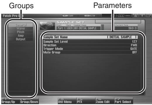
text_image
Groups Parameters Patch Pro 8 Sample SET Part 1 User Dot-Down Part 2 USER OUT-INITIAL SAMPLE Current Zone 50GB 31 Sample Set Name [ INITIAL SAMPLE ] Sample Set Level 127 Direction FWD Trigger Mode DATE Mute Group OFF F1 F2 F3 F4 F5 F6 F7 Group/Up Group/Down Opti Menu PTX Zoom Edit Part SelectF-key operations in the Patch Pro Edit screen
| F-key | Explanation | Page | |
| F1Group/Up | Moves the edit group tab upward. | - | |
| F2Group/Down | Moves the edit group tab downward. | - | |
| F3Set Stereo | This is shown if you’re editing the WAVE group. It recalls the right wave (R) from the left wave (L) of a stereo wave. | p. 130 | |
| F4Util Menu | Sample Set Initialize | Initializes the settings of the currently selected sample set. | p. 127 |
| F5PFX | Accesses the PFX (Patch Multi-effect) editing screen. | p. 157 | |
| F6Zoom Edit | Accesses the Patch Zoom Edit screen, where you can edit the most important parameters. | p. 126 | |
| F7Part Select | Selects the part to be edited. | - | |
- The parameters are organized into several editing groups. Press [F1 (Up)] or [F2 (Down)] to select the tab for the editing group that contains the parameter you wish to edit.
For details on how the parameters are grouped, refer to "Functions of Sample Set Parameters" (p. 129).
• To change the part that you want to edit
Press [F7 (Part Select)].
-
Use ▲ or ▼ to move the cursor to the parameter you wish to modify.
-
Turn the VALUE dial, or Press [INC] [DEC] to set a value.
-
Repeat steps 3–5 to set each parameter you want to edit.
- If you wish to save the changes you've made, press [WRITE] to perform the Save operation (p. 128). If you do not wish to save changes, press [EXIT] to return to the Single Play screen.
If you return to the Single Play screen without saving, the “√” symbol will be displayed at the right of the sample set name, indicating that the sample set settings have been edited.

The settings you edit are temporary, and will be lost if you turn off the power, switch the sound generator mode, or select a different sound.
Initializing Sample Set Settings (Sample Set Initialize)
"Initialize" means to return the settings of the currently selected sound to a standard set of values or to the factory settings.

The Initialize operation will affect only the currently selected sound; the sounds that are stored in user memory will not be affected. If you wish to restore all of the Fantom's settings to their factory values, perform a Factory Reset (p. 284).
- Select the sample set that you want to initialize (p. 53).
- Press [PATCH].
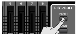
- Press [F4 (Util Menu)].
The Utility Menu window appears.
- Press ▲ or ▼ to choose "Sample Set Initialize," and then press [F8 (Select)].
To cancel, press [F7 (Cancel)].
A message will ask for confirmation.
- Press [F7 (OK)].
To cancel, press [F8 (EXIT)].
Saving Sample Sets You've Created (Write)
Changes you make to sound settings are temporary, and will be lost if you turn off the power or select another sound. If you want to keep the modified sound, you must save it in the user bank.
When you edit the sample set settings, the “√” symbol will appear in the Single Play screen. When you save the sample set, the “√” symbol will disappear.
NOTE
When you perform the save procedure, the data that previously occupied the save destination will be lost.
-
Make sure that the Sample Set you wish to save is selected.
-
Press [WRITE].
The WRITE MENU window appears.
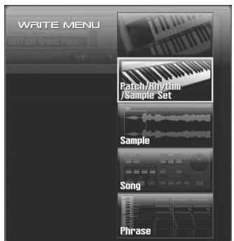
text_image
WRITE MENU DBB1-CM Grand Piano Tone Switch Patch/Braydam /Sample Set Sample Song Phrase- Select "Patch / Rhythm / Sample Set."
Press ▲ or ▼ to select "Patch / Rhythm / Sample Set," and then press [F8 (Select)].
The Sample Set Name window appears.
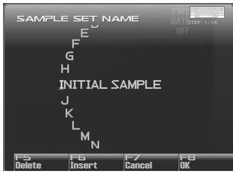
text_image
SAMPLE SET NAME E F G H INITIAL SAMPLE J K L M N F5 Delete F6 Insert F7 Cancel F8 OK- Assign a name to the sample set.
cf.
For details on assigning names, refer to “Assigning a Name” (p. 42)
- When you have finished inputting the name, press [F8 (OK)].
A screen will appear, allowing you to select the write-destination sample set.
-
Turn the VALUE dial or use [INC] [DEC] to select the sample set number.
-
Press [F8 (Write)].
A message will ask you for confirmation.
NOTE
Never switch off the Fantom-G while data is being saved.
- Press [F7 (OK)] to execute the save operation.
To cancel, press [F8 (EXIT)].
Functions of Sample Set Parameters
This section explains the functions the different sample set parameters have, as well as the composition of these parameters.
If a number is displayed for the parameter name, (1, 2, 3, 4), you can use the realtime controller knob of the corresponding number (the left most knob is number 1, the right most knob is number 4) to set the value.
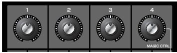
Making Settings Common to the Entire Sample Set (General)
NOTE
Sample Set Level, Sample Set MFX Switch, Sample Set Chorus Switch and Sample Set Reverb Switch applies to the entire sample set; the other parameters are set individually for each sample set tone.
Sample Set Name
Specifies the name of the sample set.
By pressing [ENTER], you can assign a name to the sample set.
Value: space, A-Z, a-z, 0-9,!" # \$ % & ' ( ) * + , - . / : ; <= > ? @ [ \ ] ^ _ ` { | }
cf.
For details on entering a name, refer to “Assigning a Name” (p. 42).
Sample Set Level
Sets the volume of the sample set.
Value: 0–127
TIP
The volume levels of the tones from which the sample set is composed is set with the Tone Level parameter (p. 131).
Direction
Specifies the direction in which the sample will play.
Value:
FWD: Play forward.
REV: Play backward.
Trigger Mode
Specifies how the sample will play when you press a pad (or key).
Value:
GATE: The sample will stop playing when you release the pad (or key).
DRUM: The sample will continue playing even after you release the pad (or key).
NOTE
The sample will begin playing when you press the pad, and will stop automatically when the end of the sample is reached. If you select the DRUM setting, the Loop setting is ignored; the sample will play only once. Note that if you select DRUM, you will not be able to interrupt the sound, so use this setting with caution if the sample is extremely long.
Mute Group
On an actual acoustic drum set, an open hi-hat and a closed hi-hat sound can never occur simultaneously. To reproduce the reality of this situation, you can set up a Mute Group.
The Mute Group function allows you to designate two or more sample tones that are not allowed to sound simultaneously. Up to 16 Mute Groups can be used. sample tones that are not belong to any such group should be set to "OFF."
Value: OFF, 1–16
Modifying Waveforms (Wave)
Sample Number L (Mono) Sample Number R
This selects the Samples comprising the sample tone. Along with the Sample number, the Sample name appears at the lower part of the display.
When in monaural mode, only the left side (L) is specified. When in stereo, the right side (R) is also specified.
Value: OFF, 0001–2000
MEMO
If you want to select a left/right pair of Samples, select the left (L) Sample number and then press [F3 (Set Stereo)]; the right (R) (Sample) will be recalled.
* When using a sample in stereo, you must specify the same number for L and R.
Wave Gain
Sets the gain (amplification) of the waveform. The value changes in 6 dB (decibel) steps—an increase of 6 dB doubles the waveform's gain.
Value: -6, 0, +6, +12
Tempo Sync (Wave Tempo Sync)
When you wish to synchronize a Phrase Loop to the clock (tempo), set this to "ON."
Value: OFF, ON
NOTE
- If a sample is selected for a tone, you must first set the BPM (tempo) parameter of the sample.
- If a sample is selected for a tone, Wave Tempo Sync will require twice the normal number of voices.
Phrase Loop
Phrase loop refers to the repeated playback of a phrase that's been pulled out of a song (e.g., by using a sampler). One technique involving the use of Phrase Loops is the excerpting of a Phrase from a pre-existing song in a certain genre, for example dance music, and then creating a new song with that Phrase used as the basic motif. This is referred to as “Break Beats.”
Realtime Time Stretch
If the Wave Tempo Sync parameter is turned "ON," you can vary the playback speed of the waveform without affecting the pitch.
Modifying Pitch (Pitch)
Tone Coarse Tune (Sample Tone Coarse Tune)
Selects the pitch at which a sample tone sounds.
Value: -48- +48
Tone Fine Tune (Sample Tone Fine Tune)
Adjusts the pitch of the sample tone's sound up or down in 1-cent steps (+/-50 cents).
Value: -50- +50
MEMO
One cent is 1/100th of a semitone.
Adjusting the Volume (Amp)
Tone Level (Sample Tone level)
Sets the volume of the sample tone. Use this parameter to adjust the volume balance between sample tones.
Value: 0–127
Tone Pan (Sample Tone Pan)
Sets the pan for the sample tone. "L64" is far left, "0" is center, and "63R" is far right.
Value: L64-0-63R
Level Velocity Sens
Set this when you want the volume of the sample tone to change depending on the force with which you press the keys. Set this to a positive (+) value to have the changes in sample tone volume increase the more forcefully the keys are played; to make the tone play more softly as you play harder, set this to a negative (-) value.
Value: -63- +63
Output Settings (Output)
Tone Output Level
Specifies the signal level for each tone.
Value: 0–127
Tone Chorus Send Level
Specifies the level of the signal sent to the chorus for each tone.
Value: 0–127
Tone Reverb Send Level
Specifies the level of the signal sent to the reverb for each tone.
Value: 0–127
Tone Output Assign
Specifies how the direct sound of each tone will be output.
Value:
PFX: Output through patch multi-effects.
DRY: Output without passing through patch multi-effects.
Setting Effects for a Sample Set (PFX)
By pressing the [F5 (PFX)] button you can access the PFX (Patch Multi-effect) editing screen (p. 157).
cf.
For details regarding effect settings, refer to the pages shown below.
- “Making Effect Settings” (p. 151)
- “Making Patch Multi-Effects Settings (PFX)” (p. 157)
With the Fantom-G, you have total control over a wide variety of settings. Each item that can be set is known as a parameter. When you change the values of parameters, you are doing what is referred to as Editing. This chapter explains the procedures used in creating Live/Studio Sets, and the functions of the Live/Studio Set parameters.
Common Settings (Utility)
Here's how to make settings that are common to the entire live set (or studio set).
- Press [LIVE] (or [STUDIO]).
- Press [F2 (Utility)].
The Utility screen will appear.
- The parameters are organized into several editing groups. Press [F1 (Up)] or [F2 (Down)] to select the tab for the editing group that contains the parameter you wish to edit.
- Press ▲ or ▼ to move the cursor to the parameter you wish to modify.
- Turn the VALUE dial or press [INC] [DEC] to get the value you want.
- If you wish to save the changes you've made, press [WRITE] to perform the Save operation (p. 148). If you do not wish to save changes, press [EXIT].
If you return to the Play screen without saving, the “√”
symbol will be displayed at the right of the live/studio set name, indicating that the patch settings have been edited.
NOTE
The settings you edit are temporary, and will be lost if you turn off the power, switch the sound generator mode, or select a different sound.
NAME
Live Set Name Studio Set Name
Specifies the name of the live/studio set.
By pressing [ENTER], you can assign a name to the live/studio set.
Value: space, A-Z, a-z, 0-9,! " # \$ % & ' ( ) * + , - . / : ; <= > ? @ [ \ ] ^ _ ` { | }
For details on entering a name, refer to “Assigning a Name” (p. 42).
Live Set Memo Studio Set Memo
You can assign a memo of up to 32 characters.
By pressing [ENTER], you can assign a memo to the live/studio set.
Value: space, A-Z, a-z, 0-9,!'' # \$ % & ' () * + ,-. / : ;<=> ? @ [ \ ] ^ _ ` { | }
Part Info
In this display you can check the receive status of various types of MIDI message for each MIDI channel. This is a convenient way to check that the sound generator is responding correctly to messages from the keyboard or external MIDI controllers.
Modulation: Modulation messages
Breath: Breath messages
Foot Type: Foot type messages
Volume: Volume messages
Panpot: Panpot messages
Expression: Expression messages
Hold 1: Hold 1 messages
Pitch Bend: Pitch Bend messages
Aftertouch: Aftertouch messages
Part Settings (Part View)
You can view the part settings as a list. This is called the "Part View" screen. In this screen you can view a list that shows settings for all parts at once, such as the patch assigned to each part, and its volume and pan settings. You can also edit these settings here.
-
Press [LIVE] (or [STUDIO]).
-
Press [F3 (Part View)].
The Part View screen will appear.
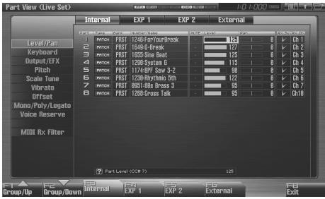
text_image
Part View (Live Set) Internal EXP 1 EXP 2 External Level/Pan Keyboard Output/UXF Pitch Scale Tone Vibrate Offset Mono/Poly/Legato Voice Reserve MIDI Rx Filter PART Level (COB 7) Group/Up Group/Down EXP 1 EXP 2 External 124 0 0 Ch 1 127 0 0 Ch 2 125 0 0 Ch 3 115 0 0 Ch 4 93 0 0 Ch 5 122 0 0 Ch 6 95 0 0 Ch 7 95 0 0 Ch10 125 124 127 125 115 93 122 95 125 125 125 125 125 125 125 125 125 125 125 125 125 125 125 125 125 125 125 125 125 125 125 125 125 130- The parameters are organized into several editing groups. Press [F1 (Up)] or [F2 (Down)] to select the tab for the editing group that contains the parameter you wish to edit.
MEMO
You can use the F-keys to switch the part group that is shown.
| F-key | Explanation |
| F3 Internal | Internal (internal sound generator) |
| F4 EXP 1 | Expansion board 1 |
| F5 EXP 2 | Expansion board 2 |
| F6 External | External MIDI output |
In the Part View screen, the edit groups that are shown will depend on the part group that's selected.
| Edit Group | F3 Internal | F4/F5 EXP 1/2 | F6 External |
| Level/Pan | √ | √ | √ |
| Keyboard | √ | √ | √ |
| Output/EFX | √ | √ | |
| Pitch | √ | √ | |
| Scale Tune | √ | √ | |
| Vibrato | √ | ||
| Offset | √ | ||
| Mono/Poly/Legato | √ | ||
| Voice Reserve | √ | ||
| MIDI Rx Filter | √ | √ | √ |
- Use [CURSOR] to move the cursor to the parameter that you want to edit.
MEMO
In this screen, the name of the parameter selected by the cursor is shown in the “?” area in the lower left of the screen. The value of the current setting is also shown here.
-
Turn the VALUE dial or press [INC] [DEC] to get the value you want.
-
If you wish to save the changes you've made, press [WRITE] to perform the Save operation (p. 148). If you do not wish to save changes, press [EXIT].
If you return to the Play screen without saving, the “√” symbol will be displayed at the right of the live/studio set name, indicating that the patch settings have been edited.
NOTE
The settings you edit are temporary, and will be lost if you turn off the power, switch the sound generator mode, or select a different sound.
Level/Pan (When the Part Group is Internal/EXP1/EXP2)
Patch Type
Sets the assignment of a patch (Patch), rhythm set (Rhythm) or sample set (Sample) to each of the parts.
Value: PATCH, RHYTHM, SAMPLE
* EXP 1 and EXP 2 parts will depend on the expansion board that is installed.
Patch Bank
Selects the group to which the desired patch or rhythm set belongs.
Value
USER: User
PRST: Preset
USAM: User Sample
GM: GM (GM2)
* EXP 1 and EXP 2 parts will depend on the expansion board that is installed.
Patch Number
Selects the desired patch, rhythm set or sample set by its number.
Value: 001–
* EXP 1 and EXP 2 parts will depend on the expansion board that is installed.
Mute Switch
Mutes (MUTE) or un-mutes (OFF) each part.
Use this setting when, for example, you want to use the instrument for karaoke by muting the part playing the melody, or when you want to play something using a separate sound module.
Value: OFF, MUTE
MEMO
The Mute Switch parameter does not turn the part off, but sets the volume to minimum so that no sound is heard. Therefore, MIDI messages are still received.
Part Level
Adjust the volume of each part. This setting's main purpose is to adjust the volume balance between parts.
Value: 0–127
Part Pan
Adjust the pan of each part. "L64" is far left, "0" is center, and "63R" is far right.
Value: L64-0-63R
Receive Switch
For each part, specify whether MIDI messages will be received (ON), or not (OFF).
If this is “OFF,” the part will not respond. Normally, you should leave this “ON,” but you can turn it “OFF” when you do not want a specific part to be playing during song playback.
Value: OFF, ON
Receive Channel
Specifies the MIDI receive channel for each part
Value: 1–16
Level/Pan (When the Part Group is External)
External Bank Select MSB
If you want a Bank Select number MSB (controller number 0) to also be transmitted when you switch Live/Studio Sets, specify the value that you want to transmit (0–127) for each part. If you do not want this message to be transmitted, set this to “---.”
Value: 0–127, ---
NOTE
The data of the part for which the Keyboard Switch is turned off will not be transmitted.
External Bank Select LSB
If you want a Bank Select number LSB (controller number 32) to also be transmitted when you switch Live/Studio Sets, specify the value that you want to transmit (0–127) for each part.
Value: 0–127, ---
NOTE
The data of the part for which the Keyboard Switch is turned off will not be transmitted.
External Program Number (External Program Change Number)
If you want a Program Change number to also be transmitted when you switch Live/Studio Sets, specify the value that you want to transmit (0–128) for each part. If you do not want this message to be transmitted, set this to “---.”
Value: 1–128, ---
NOTE
The data of the part for which the Keyboard Switch is turned off will not be transmitted.
External Level
If you want Volume messages to also be transmitted when you select a Live/Studio Set, specify the desired value (0–127) for the part. If you do not want this message to be transmitted, set this to “---.”
Value: 0–127, ---
NOTE
The data of the part for which the Keyboard Switch is turned off will not be transmitted.
External Pan
If you want Pan messages to also be transmitted when you select a Live/Studio Set, specify the desired value (L64-0-63R) for the part. If you do not want this message to be transmitted, set this to “---.”
Value: L64-0-63R, ---
NOTE
These messages will not be transmitted by parts whose Keyboard Switch is turned off.
Key Range
Keyboard Switch
Specifies, for each part, whether or not the keyboard controller section will be connected to the internal sound generator.
Normally you will leave this off; you can turn it on if you want to layer sounds.
Value: On, OFF
Keyboard Range Lower (Part Keyboard Range Lower)
Specifies the lowest note that the tone will sound for each part.
Value: C--UPPER
Keyboard Range Upper (Part Keyboard Range Upper)
Specifies the highest note that the tone will sound for each part.
Value: LOWER-G9
NOTE
When the Key Range (p. 94) is set for each individual tone in a patch, sounds are produced in the range where the Key Range of each tone and the Key Range for the part overlap.
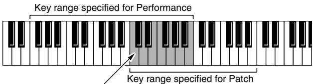
text_image
Key range specified for Performance Key range specified for PatchThe range in which notes will play
* Keyboard Range is valid only for parts whose “Keyboard Switch” (p. 135) is on.
Velocity Range Lower
For each part, specifies the bottom of the velocity range.
Value: 1–127
Velocity Range Upper
For each part, specifies the top of the velocity range.
Value: 1–127
* Velocity Range is valid only for parts whose “Keyboard Switch” (p. 135) is on.
NOTE
When the Velocity Range (p. 95) is set for each individual tone in a patch, sounds are produced in the range where the Key Range of each tone and the Key Range for the part overlap.
Part Velocity Sens Offset
This changes the volume and cutoff frequency for each part according to the velocity with which the keys are pressed. If you want strongly played notes to raise the volume/cutoff frequency, set this parameter to positive (+) settings. If you want strongly played notes to lower the volume/cutoff frequency, use negative (-) settings. Set Velocity Sensitivity to “0” when you want sounds played at a fixed volume and cutoff frequency, regardless of the force with which the keys are played.
Value: -63- +63
NOTE
Patches also contain a Velocity Sensitivity Offset setting (p. 91). The ultimate Velocity Sensitivity Offset value is the sum of the part's and the patch's Velocity Sensitivity Offsets. Accordingly, if the patch's Velocity Sensitivity Offset parameter is set to "127" (maximum), there will be no change in the part's Velocity Sensitivity Offset, even when this is set to a positive value.
* EXP 1, EXP 2, and External parts do not have this item.
Arpeggio Part Switch
Specifies the part that will use the Arpeggio function.
Value: OFF, ON
Sample Pad Part Switch
Specifies the Sample Pad Part.
Value: OFF, ON
Rhythm Pad Part Switch
Specifies the Rhythm Pad Part.
Value: OFF, ON
Output/EFX
Part Output Assign
Specifies for each part how the direct sound will be output.
Value
A, B: Output to the OUTPUT A (MIX) jack or OUTPUT B jack in stereo without passing through multi-effects.
1-4: Output to the INDIVIDUAL 1-4 jacks in mono without passing through multi-effects.
MFX1, MFX2:
Output in stereo through multi-effects. *Studio set only
In the case of parts EXP1, EXP2:
DRY: Output without being passed through the expansion board's MFX.
EXP: Accords with the settings of the expansion board.
NOTE
If you've made settings so that sounds are separately routed to the INDIVIDUAL 1 jack and INDIVIDUAL 2 jack, but no plug is actually inserted in the INDIVIDUAL 2 jack, the sounds routed to INDIVIDUAL 1 and INDIVIDUAL 2 will be mixed and output from the INDIVIDUAL 1 jack. This is due to the mechanism of the INDIVIDUAL 1 and 2 jacks.
MEMO
If the Mix/Parallel parameter is set to "MIX," all sounds are output from the OUTPUT A (MIX) jacks in stereo (p. 298).
TIP
Chorus are output in mono at all times.
- The output destination of the signal after passing through the chorus is set with the Chorus Output Select (p. 153) and the Chorus Output Assign (p. 153).
- The output destination of the signal after passing through the reverb is set with the Reverb Output Assign (p. 153).
* EXP 1 and EXP 2 parts will depend on the expansion board that is installed.
* External parts do not have this item.
Part Output Level
Set the level of the signal that is sent to the output destination specified by Part Output Assign.
Value: 0–127
* EXP 1 and EXP 2 parts will depend on the expansion board that is installed.
* External parts do not have this item.
Part Chorus Send Level
Sets the level of the signal sent to chorus for each part.
Value: 0–127
* External parts do not have this item.
Part Reverb Send Level
Sets the level of the signal sent to reverb for each part.
Value: 0–127
* External parts do not have this item.
Part EFX1 Send Level (Expansion part effect 1: Send Level)
Sets the level of the signal sent to "EFX 1 (Effect 1)" for each part of the expansion board.
Value: 0–127
* "EFX1 (Effect 1)" is an effect on the expansion board. The content of the effect will depend on the expansion board that's installed.
* Internal and External parts do not have this item.
Part EFX2 Send Level (Expansion part effect 2: Send Level)
Sets the level of the signal sent to "EFX 2 (Effect 2)" for each part of the expansion board.
Value: 0–127
* "EFX2 (Effect 2)" is an effect on the expansion board. The content of the effect will depend on the expansion board that's installed.
* Internal and External parts do not have this item.
Pitch
Part Octave Shift
Adjusts the pitch of the part's sound up or down in units of an octave (+/-3 octaves).
Value: -3- +3
Part Transpose
Adjusts the pitch of the part's sound up or down in semitone steps.
Value: -5- +6
Part Coarse Tune
Adjusts the pitch of the part's sound up or down in semitone steps (+/-4 octaves).
Value: -48- +48
* EXP 1 and EXP 2 parts will depend on the expansion board that is installed.
* External parts do not have this item.
Coarse Tune and Octave Shift
The Coarse Tune and Fine Tune parameters, along with the Octave Shift parameter, can all be seen as doing the same thing to the sound, i.e., changing the pitch of the sound. For example, if C4 (Middle C) is played with the Coarse Tune parameter set to “+12,” the note produced is C5 (one octave above C4). For example, if C4 (Middle C) is played with the Octave Shift parameter set to “+1,” the note produced is C5 (one octave above C4).
However, internally these function very differently. When the Coarse Tune parameter is set to “+12,” the pitch itself is raised one octave. On the other hand, when the Octave Shift parameter is set to “+1,” it is the same as pressing the keys one octave up. In other words, use the Coarse Tune parameter when changing the pitch, and the Octave Shift parameter when you want to shift the entire keyboard, for example, when the number of keys is insufficient.
Part Fine Tune
Adjusts the pitch of the part's sound up or down in 1-cent steps (+/-50 cents).
Value: -50- +50
MEMO
One cent is 1/100th of a semitone.
* EXP 1 and EXP 2 parts will depend on the expansion board that is installed.
* External parts do not have this item.
Part Pitch Bend Range
Specifies the amount of pitch change in semitones (2 octaves) that will occur when the Pitch Bend Lever is moved. The amount of change when the lever is tilted is set to the same value for both left and right sides. If you want to use the Pitch Bend Range setting of the patch assigned to the part (p. 96), set this to "PATCH."
Value: 0–24, PATCH
* EXP 1 and EXP 2 parts will depend on the expansion board that is installed.
* External parts do not have this item.
Part Portamento Switch
Specify whether portamento will be applied. Turn this parameter "ON" when you want to apply Portamento and "OFF" when you don't. If you want to use the Portamento Switch setting of the patch assigned to the part (p. 106), set this to "PATCH."
Value: OFF, ON, PATCH
* EXP 1, EXP 2, and External parts do not have this item.
Part Portamento Time
When portamento is used, this specifies the time over which the pitch will change. Higher settings will cause the pitch change to the next note to take more time. If you want to use the Portamento Time setting of the patch assigned to the part (p. 106), set this to "PATCH."
Value: 0–127, PATCH
NOTE
This setting is ignored for parts to which a rhythm set is assigned.
* EXP 1, EXP 2, and External parts do not have this item.
Scale Tune
Part Scale Tune C-B
Make scale tune settings for each part.
Value: -64- +63
NOTE
Scale Tune is switched on/off by means of the Scale Tune Switch parameter (p. 300).
* EXP 1 and EXP 2 parts will depend on the expansion board that is installed.
* External parts do not have this item.
Equal Temperament
This tuning divides the octave into 12 equal parts, and is the most widely used method of temperament used in Western music. The Fantom-G employs equal temperament when the Scale Tune Switch is set to "OFF."
Just Temperament (Tonic of C)
Compared with equal temperament, the principle triads sound pure in this tuning. However, this effect is achieved only in one key, and the triads will become ambiguous if you transpose.
Arabian Scale
In this scale, E and B are a quarter note lower and C#, F# and G# are a quarter-note higher compared to equal temperament. The intervals between G and B, C and E, F and G#, Bb and C#, and Eb and F# have a natural third—the interval between a major third and a minor third. On the Fantom-G, you can use Arabian temperament in the three keys of G, C and F.
| Note name | Equal temperament | Just Temperament (tonic C) | Arabian Scale |
| C | 0 | 0 | -6 |
| C# | 0 | -8 | +45 |
| D | 0 | +4 | -2 |
| Eb | 0 | +16 | -12 |
| E | 0 | -14 | -51 |
| F | 0 | -2 | -8 |
| F# | 0 | -10 | +43 |
| G | 0 | +2 | -4 |
| G# | 0 | +14 | +47 |
| A | 0 | -16 | 0 |
| Bb | 0 | +14 | -10 |
| B | 0 | -12 | -49 |
Vibrato
Part Vibrato Rate
For each part, adjust the vibrato speed (the rate at which the pitch is modulated). The pitch will be modulated more rapidly for higher settings, and more slowly with lower settings.
Value: -64- +63
* EXP 1, EXP 2, and External parts do not have this item.
Part Vibrato Depth
For each part, this adjusts the depth of the vibrato effect (the depth at which the pitch is modulated). The pitch will be modulated more greatly for higher settings, and less with lower settings.
Value: -64- +63
* EXP 1, EXP 2, and External parts do not have this item.
Part Vibrato Delay
For each part, this adjusts the time delay until the vibrato (pitch modulation) effect begins. Higher settings will produce a longer delay time before vibrato begins, while lower settings produce a shorter time.
Value: -64- +63
* EXP 1, EXP 2, and External parts do not have this item.
Offset
Part Cutoff Offset
Adjusts the cutoff frequency for the patch, rhythm set or sample set assigned to a part.
Value: -64- +63
NOTE
Patches also have a Cutoff Offset setting (p. 90). The final Cutoff frequency value is the sum of the tone Cutoff Frequency value and the patch and part Cutoff Offset values. If the tone's cutoff frequency is already set to "127" (maximum), there will be no change produced by setting the Cutoff Offset to a positive value.
* EXP 1, EXP 2, and External parts do not have this item.
Part Resonance Offset
Adjusts the Resonance for the patch, rhythm set or sample set assigned to a part.
Value: -64- +63
NOTE
Patches also have a Resonance Offset setting (p. 91). The final Resonance value is the sum of the tone Resonance value and the patch and part Resonance Offset values. If the tone's resonance is already set to "127" (maximum), there will be no change produced by setting the resonance offset to a positive value.
* EXP 1, EXP 2, and External parts do not have this item.
Part Attack Time Offset
Adjusts the TVA/TVF Envelope Attack Time for the patch, rhythm set or sample set assigned to a part.
Value: -64- +63
NOTE
Patches also contain the Attack Time Offset setting (p. 91). The final TVA Envelope attack time value is therefore the sum of the tone's TVA Envelope Time 1 setting, the patch's Attack Time Offset, and the part's Attack Time Offset. If the tone's Time 1 parameter is already set to "127" (maximum), there will be no change produced by setting the Attack Time Offset to a positive value. The same applies to the TVF envelope.
* EXP 1, EXP 2, and External parts do not have this item.
Part Decay Time Offset
Adjusts the TVA/TVF Envelope Decay Time for the patch or rhythm set assigned to a part.
Value: -64- +63
NOTE
This setting is ignored for parts to which a sample set is assigned.
* EXP 1, EXP 2, and External parts do not have this item.
Part Release Time Offset
Adjusts the TVA/TVF Envelope Release Time for the patch, rhythm set or sample set assigned to a part.
Value: -64- +63
NOTE
Patches also contain a Release Time Offset setting (p. 91). The final TVA Envelope release time value is therefore the sum of the tone's TVA Envelope Time 4 setting, the patch's Release Time Offset, and the part's Release Time Offset. If the tone's Time 4 parameter is set to "127" (maximum), there will be no change in the Release Time Offset, even when this is set to a positive value. The same applies to the TVF envelope.
* EXP 1, EXP 2, and External parts do not have this item.
Mono/Poly/Legato
Part Mono/Poly
Set this parameter to “MONO” when the patch assigned to the part is to be played monophonically, or to “POLY” when the patch is to be played polyphonically. If you want to use the Mono/Poly setting of the patch assigned to the part (p. 105), set this to “PATCH.”
Value: MONO, POLY, PATCH
NOTE
This setting is ignored for parts to which a rhythm set is assigned.
* EXP 1, EXP 2, and External parts do not have this item.
Part Legato Switch
You can add legato when performing monophonically. The term "legato" refers to a playing style in which notes are smoothly connected to create a flowing feel. This creates a smooth transition between notes, which is effective when you wish to simulate the hammering-on and pulling-off techniques used by a guitarist.
Turn this parameter "ON" when you want to use the Legato feature and "OFF" when you don't. If you want to use the Legato Switch setting of the patch assigned to the part (p. 105), set this to "PATCH."
Value: OFF, ON, PATCH
NOTE
This setting is ignored for parts to which a rhythm set is assigned.
* EXP 1, EXP 2, and External parts do not have this item.
Voice Reserve
Part Voice Reserve
This setting specifies the number of voices that will be reserved for each part when more than 128 voices are played simultaneously.
Value: 0–63, FULL
NOTE
It is not possible for the settings of all parts to total an amount greater than 64. The remaining number of available voices will be displayed at (rest=). Pay attention to this readout as you make Voice Reserve settings.
NOTE
When playing audio tracks in a song, audio track playback will take priority over voice reserve settings. This means that if audio tracks are playing back, it may not be possible to guarantee the polyphony specified by the voice reserve settings.
Calculating the Number of Voices Being Used
The Fantom-G is able to play up to 128 notes simultaneously. The polyphony, or the number of voices (sounds) does not refer only to the number of sounds actually being played, but changes according to the number of tones used in the patches, and the number of Waves used in the tones. The following method is used to calculate the number of sounds used for one patch being played.
(Number of Sounds Being Played) x (Number of Tones Used by Patches Being Played) x (Number of Waves Used in the Tones) Realtime Stretch requires twice the normal polyphony.
Voice Monitor
Here's how you can see a graphic indication of the number of voices used by the sound generator.
MIDI Rx Filter
Receive Program Change (Receive Program Change Switch)
For each MIDI channel, specify whether MIDI Program Change messages will be received (ON), or not (OFF).
Receive Bank Select (Receive Bank Select Switch)
For each MIDI channel, specify whether MIDI Bank Select messages will be received (ON), or not (OFF).
Receive Bender (Receive Pitch Bend Switch)
For each MIDI channel, specify whether MIDI Pitch Bend messages will be received (ON), or not (OFF).
Receive Polyphonic Key Pressure (Receive Polyphonic Key Pressure Switch)
For each MIDI channel, specify whether MIDI polyphonic key pressure messages will be received (ON), or not (OFF).
Receive Channel Pressure (Receive Channel Pressure Switch)
For each MIDI channel, specify whether MIDI Channel Pressure messages will be received (ON), or not (OFF).
Receive Modulation (Receive Modulation Switch)
For each MIDI channel, specify whether MIDI Modulation messages will be received (ON), or not (OFF).
Receive Volume (Receive Volume Switch)
For each MIDI channel, specify whether MIDI Volume messages will be received (ON), or not (OFF).
Receive Pan (Receive Pan Switch)
For each MIDI channel, specify whether MIDI Pan messages will be received (ON), or not (OFF).
Receive Expression (Receive Expression Switch)
For each MIDI channel, specify whether MIDI Expression messages will be received (ON), or not (OFF).
Receive Hold-1 (Receive Hold 1 Switch)
For each MIDI channel, specify whether MIDI Hold 1 messages will be received (ON), or not (OFF).
Phase Lock (Phase Lock Switch)
Set Phase Lock to "ON" when you want to suppress discrepancies in timing of parts played on the same MIDI channel.
NOTE
When the Phase Lock parameter is set to “ON,” parts on the same MIDI channel are put in a condition in which their timing is matched, enabling them to be played at the same time. Accordingly, a certain amount of time may elapse between reception of the Note messages and playing of the sounds. Turn this setting to “ON” only as needed.
* This will not affect expansion boards.
Velocity Curve Type
Velocity Curve selects for each MIDI channel one of the four following Velocity Curve types that best matches the touch of the connected MIDI keyboard. Set this to “OFF” if you are using the MIDI keyboard’s own velocity curve.
Value: OFF, 1–4
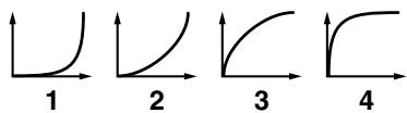
* This will not affect expansion boards.
Selecting the Parameter Controlled by the Realtime Controllers or D Beam Controller (Control Setting)
The Fantom-G lets you assign the parameters that will be affected when you operate the realtime control knobs, assignable switches, D Beam, pitch bend, or modulation lever. This lets you modify the sound in a variety of ways by operating the controllers.
- Press [LIVE] (or [STUDIO]).
- Press [F4 (Control)].
The Control Setting screen appears.
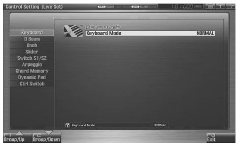
text_image
Control Setting (Live Sat) Keyboard O Beam Knob Slider Switch S1/S2 Arpeglio Chord Memory Dynamic Pad Ctrl Switch Keyboard Mode NORMAL F1 F2 F3 Group/Up Group/Down Exit-
The parameters are organized into several editing groups. Press [F1 (Up)] or [F2 (Down)] to select the tab for the editing group that contains the parameter you wish to edit.
-
Use [CURSOR] to move the cursor to the parameter that you want to edit.
-
Turn the VALUE dial or press [INC] [DEC] to get the value you want.
-
Repeat steps 3-5 to set each parameter you want to edit.
-
The settings for the Solo Synth are saved for the system settings. Press [F7 (Sys Write)] to execute the write operation.
-
The settings in the Control Setting screen are saved independently for each live/studio set. If you wish to save the changes you've made, press [WRITE] to perform the Save operation (p. 148). If you do not wish to save changes, press [EXIT].
If you return to the Play screen without saving, the "√" symbol will be displayed at the right of the live/studio set name, indicating that the patch settings have been edited.
NOTE
The settings you edit are temporary, and will be lost if you turn off the power, switch the sound generator mode, or select a different sound.
Keyboard Mode
Keyboard Mode
If you choose RPS or RHYTHM-PTN, you can use the keyboard to play RPS or Rhythm Pattern Sets. The keys that will play RPS / Rhythm Pattern Sets can be specified as described in "Note
Number" (p. 195, p. 196).
Value
NORMAL: Normal keyboard performance mode
RPS: RPS performance mode
RHYTHM-PTN: Rhythm Pattern performance mode
MEMO
The Keyboard Mode setting is not saved in Single mode. When you press [SINGLE], the Keyboard Mode will be initialized to NORMAL.
D Beam
D Beam Switch
Specifies the operating mode of the D Beam controller.
Value:
OFF: The D Beam will not be used.
PAD TRIGGER: This allows you to use the D Beam controller to sound the pads as an alternative to striking the pads.
SOLO SYNTH: This allows you to use the D Beam controller as a monophonic synthesizer.
ASSIGNABLE: The Fantom-G will control the function you assign.
MEMO
The parameters shown in the screen will depend on the choice you make here.
D Beam: PAD TRIGGER
Instead of striking the pads themselves, you can also use the D Beam controller to control the sounding of the pads.
Beam Trigger Pad
Specifies the pad number affected by the D Beam.
Value: Pad 1–Pad 16
Beam Trigger Velo (Beam Trigger Velocity)
Specifies the strength of the pad sound played by the D Beam controller.
Value: 1–127
Beam Trigger Mode
This specifies how the D Beam will behave when it is obstructed. If this is set to MOMENTARY, the parameter will be on only while the D Beam is obstructed, and will turn off when you stop obstructing it. If this is set to LATCH, the parameter will alternately be switched on/off each time you obstruct the D Beam.
Value: MOMENTARY, LATCH
D Beam: SOLO SYNTH
You can use the D Beam controller to perform in a way similar to on a mono synth.
TIP
Settings for the Solo Synth are saved for system settings. Press [F7 (Sys Write)] to execute the write operation.
MEMO
In this screen, the name of the parameter selected by the cursor
is shown in the “?” area in the lower left of the
screen. The current value of the setting is also shown here.
OSC 1/2 Waveform
Select the waveform. SAW is a sawtooth wave, and SQR is a square wave.
Value: SAW, SQR
OSC 1/2 Pulse Width
Specifies the pulse width of the waveform. By cyclically modifying the pulse width you can create subtle changes in the tone.
* The Pulse Width is activated when "SQR" is selected with OSC1/2 waveform.
Value: 0–127
LFO Osc 1 Pulse Width Depth
Specifies the depth to which the LFO will modulate the pulse width of the OSC1 waveform.
* The Pulse Width is activated when "SQR" is selected with OSC1/2 waveform.
Value: -63- +63
LFO Osc 2 Pulse Width Depth
Specifies the depth to which the LFO will modulate the pulse width of the OSC2 waveform.
* The Pulse Width is activated when "SQR" is selected with OSC1/2 waveform.
Value: -63- +63
LFO Osc 1 Pitch Depth
Specifies the depth to which the LFO will modulate the OSC1 pitch.
Value: -63- +63
LFO Osc 2 Pitch Depth
Specifies the depth to which the LFO will modulate the OSC2 pitch.
Value: -63- +63
OSC 1/2 Coarse Tune
Adjusts the pitch of the tone's sound up or down in semitone steps (+/-4 octaves).
Value: -48- +48
OSC 1/2 Fine Tune
Adjusts the pitch of the tone's sound up or down in 1-cent steps (+/-50 cents).
Value: -50- +50
OSC Sync Switch
Turning this switch on produces a complex sound with many harmonics. This is effective when the OSC1 pitch is higher than the OSC2 pitch.
Value: OFF, ON
OSC2 Level
Adjust the level.
Value: 0–127
Filter Type
Selects the type of filter.
OFF: No filter is used.
LPF: Low Pass Filter. This reduces the volume of all frequencies above the cutoff frequency (Cutoff Freq) in order to round off, or un-brighten the sound.
BPF: Band Pass Filter. This leaves only the frequencies in the region of the cutoff frequency, and cuts the rest.
HPF: High Pass Filter. This cuts the frequencies in the region below the cutoff frequency.
PKG: Peaking Filter. This emphasizes the frequencies in the region of the cutoff frequency.
Cutoff
Selects the frequency at which the filter begins to have an effect on the waveform's frequency components.
Value: 0–127
Resonance
Emphasizes the portion of the sound in the region of the cutoff frequency, adding character to the sound.
Value: 0–127
LFO Rate
Adjusts the modulation rate, or speed, of the LFO.
Value: 0–127
Range (Solo synth range)
Specifies the range in which the pitch of the solo synth will vary.
Value: 2 OCTAVES, 4 OCTAVES, 8 OCTAVES
Chorus Send Level
Sets the level of the signal sent to chorus.
Value: 0–127
Reverb Send Level
Sets the level of the signal sent to reverb.
Value: 0–127
Level
Sets the volume.
Value: 0–127
D Beam: ASSIGNABLE
By assigning a variety of functions to the D Beam controller you can apply different effects to the sound in real time.
TIP
The settings for the ASSIGNABLE are saved independently for each live/studio set as part of the live/studio set settings. This lets you create live/studio sets that make effective use of controller settings.
Type (Assignable Type)
Specifies the function controlled by the D Beam controller.
Value
OFF: Off
CC01-31, CC32(OFF), 33-95:
Control Change
AFTERTOUCH: Aftertouch
BEND UP: Controls the pitch as specified by the "Pitch Bend Range Up" setting (p. 96).
BEND DOWN: Controls the pitch as specified by the "Pitch Bend Range Down" setting (p. 96).
ARPEGGIO ACCENT: Arpeggio accent rate
ARPEGGIO SHUFFLE: Arpeggio shuffle rate
ARPEGGIO OCT UP: The range in which the arpeggio is sounded will rise in steps of an octave.
ARPEGGIO OCT DOWN: The range in which the arpeggio is sounded will lower in steps of an octave.
Range Min (D Beam Range Lower)
Specify the lower limit of the range of the D Beam controller.
Value: 0–127
Range Max (D Beam Range Upper)
Specify the upper limit of the range of the D Beam controller. By setting Range Max below Range Min you can invert the range of change.
Value: 0–127
Knob
Knob Assign 1-4
Specify the functions that will be controlled by the knobs.
Value
OFF: Off
CC01-31, CC32(OFF), 33-95:
Control Change
AFTERTOUCH: Aftertouch
PITCH BEND: Pitch Bend
ARPEGGIO ACCENT: Arpeggio accent rate
ARPEGGIO SHUFFLE: Arpeggio shuffle rate
ARPEGGIO OCT UP: The range in which the arpeggio is sounded will rise in steps of an octave.
ARPEGGIO OCT DOWN: The range in which the arpeggio is sounded will lower in steps of an octave.
MASTER LEVEL: Master Level (p. 297)
DIGITAL/USB INPUT LEVEL:
Digital/USB Input Level (p. 258)
* The system setting will be used if the system parameter “Knob Assign Source” (p. 293) is set to “System,” and the setting of the live set or studio set will be used if it is set to “TEMP.”
Slider
Slider 1-8 Assign
Specify the functions that will be controlled by the sliders.
Value
OFF: Off
CC01-31, CC32(OFF), 33-95:
Control Change
AFTERTOUCH: Aftertouch
PITCH BEND: Pitch Bend
ARPEGGIO ACCENT: Arpeggio accent rate
ARPEGGIO SHUFFLE: Arpeggio shuffle rate
ARPEGGIO OCT UP: The range in which the arpeggio is sounded will rise in steps of an octave.
ARPEGGIO OCT DOWN: The range in which the arpeggio is sounded will lower in steps of an octave.
* The system setting will be used if the system parameter “Slider Assign Source” (p. 293) is set to “System,” and the setting of the live set or studio set will be used if it is set to “TEMP.”
Switch S1/S2
Switch S1/S2 Assign
Specify the functions that will be controlled by the [S1] [S2] switches.
Value
Live Set: OFF, CC01 - CC31, CC32 (OFF), CC33 - CC95, AFTERTOUCH, MONO/POLY, PFX SWITCH, MFX SWITCH, RESERVE, CHORUS SWITCH, REVERB SWITCH, MASTERING SWITCH, MASTER KEY UP, MASTER KEY DOWN, SCALE TUNE SWITCH
Studio Set: OFF, CC01 - CC31, CC32 (OFF), CC33 - CC95, AFTERTOUCH, MONO/POLY, PFX SWITCH, MFX1 SWITCH, MFX2 SWITCH, CHORUS SWITCH, REVERB SWITCH, MASTERING SWITCH, MASTER KEY UP, MASTER KEY DOWN, SCALE TUNE SWITCH
Switch S1/S2 Assign Mode
Turns the [S1] [S2] switches function LATCH/MOMENTARY.
Value
LATCH: The on/off status will alternate each time you press [S1] [S2].
MOMENTARY: The status will be on only while you hold down [S1] [S2].
Arpeggio
Arpeggio Switch
Turns the Arpeggio function (p. 78) on/off.
Value: ON, OFF
Arpeggio Hold
Turns the Arpeggio Hold function (p. 78) on/off.
Value: ON, OFF
Arpeggio Number
Specifies the arpeggio number.
Value: 001–128
Arpeggio Part Group
Selects the part group that will use the Arpeggio function: internal (INT), expansion board 1 (EXP1), expansion board 2 (EXP2), or external MIDI output (EXT).
Value: INT, EXP1, EXP2, EXT
Arpeggio Part Number
Specifies the part that will use the Arpeggio function.
Value: Part1–16
Chord Memory
Chord Switch
Turns the Chord Memory function (p. 81) on/off.
Value: ON, OFF
Chord Form
Specifies the Chord Form (p. 81).
Value: 001–128
Rolled Chord
Turns the Rolled Chord function (p. 82) on/off.
Value: ON, OFF
Rolled Chord Type
Specifies the Rolled Chord Type (p. 82).
Value
UP: Notes will be sounded in order from bottom to top.
DOWN: Notes will be sounded in order from top to bottom.
ALTERNATE: The order in which the notes are sounded will change each time you play the keyboard.
L-DOWN: The lowest note will be sounded first, and then notes will be sounded in order from the top down.
* If you press C E G B, the notes will be sounded as C B G E.
U-UP: The highest note will be sounded first, and then notes will be sounded in order from the bottom up.
* If you press C E G B, the notes will be sounded as B C E G.
Dynamic Pad
Rhythm Pad Part Group
Selects the rhythm pad part group: internal (INT), expansion board 1 (EXP1), expansion board 2 (EXP2), or external MIDI output (EXT).
Value: INT, EXP1, EXP2, EXT
Rhythm Pad Part Number
Specifies the Rhythm Pad Part.
Value: Part1–16
Sample Pad Part Number
Specifies the Sample Pad Part.
Value: Part1–16
Ctrl Switch
You can change controller switch on/off settings for each part.
MEMO
You can use the F-keys to switch the part group that is displayed.
| F-key | Explanation |
| F3 Internal | Internal (internal sound generator) |
| F4 EXP 1 | Expansion board 1 |
| F5 EXP 2 | Expansion board 2 |
| F6 External | External MIDI output |
MEMO
In this screen, the name of the parameter selected by the cursor is shown in the “?” area in the lower left of the screen. The current value of the setting is also shown here.
Control Bender (Control Pitch Bend Switch)
For each part, specify whether MIDI Pitch Bend messages will be transmitted (ON), or not (OFF).
Value: OFF, ON
Control Aftertouch (Control Aftertouch Switch)
For each part, specify whether MIDI Aftertouch messages will be transmitted (ON), or not (OFF).
Value: OFF, ON
Control Modulation (Control Modulation Switch)
For each part, specify whether MIDI Modulation messages will be transmitted (ON), or not (OFF).
Value: OFF, ON
Control Hold Pedal (Control Hold Pedal Switch)
For each part, you can specify whether control messages from a pedal connected to the HOLD PEDAL jacks will be transmitted (ON), or not (OFF).
Value: OFF, ON
Control Pedal 1, 2 (Control Pedal 1, 2 Switch)
For each part, you can specify whether control messages from a pedal connected to the CONTROL PEDAL 1, 2 jacks will be transmitted (ON), or not (OFF).
Value: OFF, ON
Changing the Settings of the Patch Assigned to a Part
When using patches in Live/Studio Mode, some settings such as effects settings will be affected by Live/Studio Set settings. If you wish to edit a patch while hearing how it will sound in the Live/Studio Set, use this procedure:
* Here we explain how to change the setting of a patch assigned to a part. The procedure for changing the settings of rhythm sets or sample sets is the same. Substitute “rhythm set” or “sample set” wherever “patch” appears in a sentence.
- Make sure the Live Mode (or the Studio Mode) is selected.
- Press [PATCH] twice.
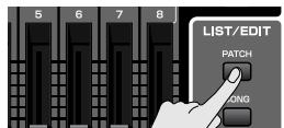
The patch assigned to the part is displayed in the Patch Pro Edit screen.
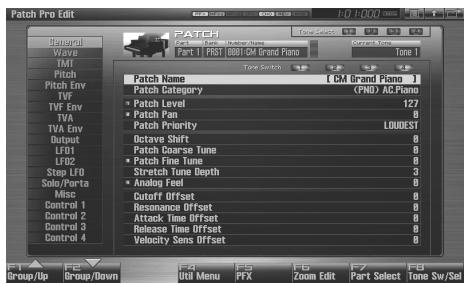
text_image
Patch Pro Edit PATCH Wave TMI Pitch Patch Env TVF TVF Env TVA TVA Env Output LFO1 LFO2 Step LFO Solo/Porta Misc Control 1 Control 2 Control 3 Control 4 F1 Group/Up Group/Down F2 Util Menu F3 PFX F4 Zoom Edit F5 Part Select F6 Tone Sw/Sel Punch Name [CM Grand Piano] Patch Category (PNU) ALPiano Patch Level 127 Patch Icon 0 Patch Priority LOUDEST Octave Shift 0 Patch Coarse Tune 0 Patch Fine Tune 0 Stretch Tone Depth 3 Analog Test 0 Cutoff Offset 0 Resonance Offset 0 Attack Time Offset 0 Release Time Offset 0 Velocity Sens Offset 0- The rest of the procedure is the same as when making changes in Single mode (p. 84).
Initializing Live/Studio Set Settings (Init)
"Initialize" means to return the settings of the currently selected sound to a standard set of values.
NOTE
The Initialize operation will affect only the currently selected sound; the sounds that are stored in user memory will not be affected. If you wish to restore all of the Fantom-G's settings to their factory values, perform a Factory Reset (p. 284).
-
Select the Live/Studio Set that you wish to initialize.
-
Press [F2 (Utility)].
-
Press [F6 (Initialize)].
The Live/Studio Set Initialize Menu window will appear.
-
Press ▲ or ▼ to select the initialization type.
-
Default: Resets the currently selected Live/Studio set in the Temporary memory to the standard values. Use this setting when you wish to create a sound from scratch.
• Sound Control: Initializes the values of the following part parameters. Cutoff Offset, Resonance Offset, Attack Time Offset, Release Time Offset, Decay Time Offset, Vibrato Rate, Vibrato, Depth, Vibrato Delay -
Press [F8 (Select)].
A message will ask you for confirmation.
- Press [F7 (OK)] to execute.
To cancel, press [F8 (EXIT)].
Saving a Live/Studio Set You've Created (Write)
The settings you edit are temporary, and will be lost if you turn off the power, switch the sound generator mode, or select a different sound. If you want to keep the modified sound, you must save it in the User bank.
When you modify the settings of a Live/Studio Set, the Live/Studio Play screen will indicate “√.” Once you save the Live/Studio Set into user area, the “√” indication goes away.
NOTE
When you perform the save procedure, the data that previously occupied the save destination will be lost.
- Make sure that the live/studio set you wish to save is selected.
- Press [WRITE].
The WRITE MENU window appears.
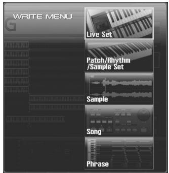
text_image
WRITE MENU Live Set Patch/Rhythm /Sample Set Sample Song Phrase- Select "Live Set / Studio Set."
Alternatively, you can use CURSOR ▲ or ▼ to select "Live Set / Studio Set" and then press [F8 (Select)]. The Live Set/Studio Set Name window appears.
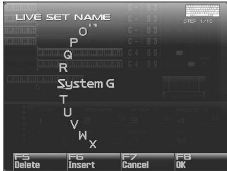
text_image
LIVE SET NAME O P Q R System G T U V W X F5 Delete F6 Insert F7 Cancel F8 OK- Assign a name to the live/studio set.
cf.
For details on assigning names, refer to “Assigning a Name” (p. 42)
- When you have finished inputting the name, press [F8 (OK)].
A screen will appear, allowing you to select the write-destination live/studio set.
-
Turn the VALUE dial or use [INC] [DEC] to select the live/studio set number.
-
Press [F8 (Write)].
A message will ask you for confirmation.
NOTE
Never switch off the Fantom-G while data is being saved.
- Press [F7 (OK)] to execute the save operation.
To cancel the operation, press [F8 (EXIT)].
When Changing the Settings for the patch, rhythm set or sample set assigned to a Part in a Live/Studio Set
If you've edited a patch, rhythm set or sample set assigned to a part in a live/studio set and then try to save the live/studio set without first saving the edited patch, rhythm set or sample set, the following message appears.
Edited patch, rhythm set or sample set will be discard, Are you sure?
In such cases, first save the patches and rhythm sets, and then save the live/studio set.
This section explains the procedures and settings for applying effects in each mode.
cf.
For details of the Fantom-G's onboard effects, refer to “About the Internal Effects” (p. 36).
Where Effect Settings are Saved
Effect settings are saved in the locations shown in the illustration below. If you want to save your effect settings, press the [WRITE] button and save them in the patch, live set, studio set, or system.
● Single Mode
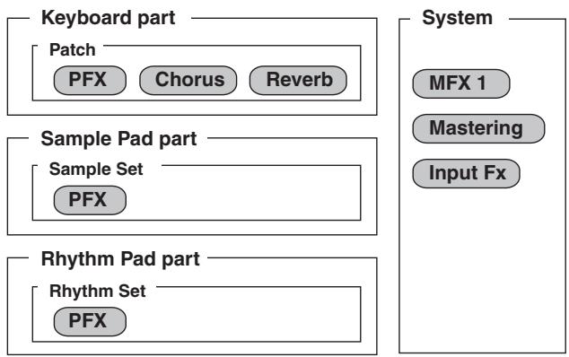
flowchart
graph TD
    A["Keyboard part"] --> B["Patch"]
    B --> C["PFX"]
    B --> D["Chorus"]
    B --> E["Reverb"]
    F["Sample Pad part"] --> G["Sample Set"]
    G --> H["PFX"]
    I["Rhythm Pad part"] --> J["Rhythm Set"]
    J --> K["PFX"]
    L["System"] --> M["MFX 1"]
    L --> N["Mastering"]
    L --> O["Input Fx"]
● Live Mode
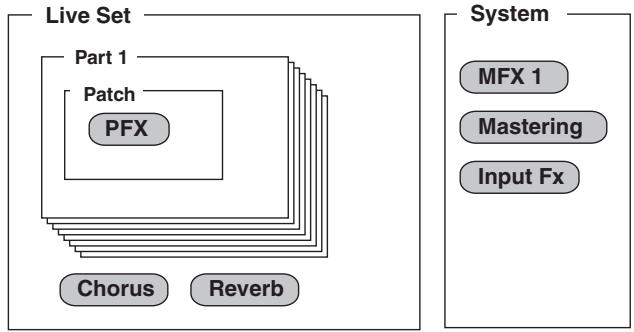
flowchart
graph TD
    A["Live Set"] --> B["Part 1"]
    A --> C["Patch"]
    A --> D["PFX"]
    A --> E["Chorus"]
    A --> F["Reverb"]
    G["System"] --> H["MFX 1"]
    G --> I["Mastering"]
    G --> J["Input Fx"]
- Studio Mode
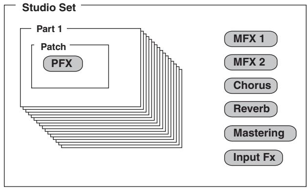
flowchart
graph TD
    A["Studio Set"] --> B["Part 1"]
    A --> C["Patch"]
    A --> D["PFX"]
    E["MFX 1"] --> F["Output"]
    G["MFX 2"] --> H["Output"]
    I["Chorus"] --> J["Output"]
    K["Reverb"] --> L["Output"]
    M["Mastering"] --> N["Output"]
    O["Input Fx"] --> P["Output"]
Turning Effects On and Off
The Fantom-G's onboard effects can be turned on/off. Turn these settings OFF when you wish to listen to the unprocessed sound as you create a sound, or when you wish to use external effects processors instead of the built-in effects.
1. Press [EFFECTS (ROUTING)] to access the Effects screen.
![ROLAND FANTOM G8 - Press [EFFECTS (ROUTING)] to access the Effects screen. - 1](/content/2025/01/130804/images/32c578667c29c892502dea6e8c553f5162f0e8d3447a37d63468a8a070ec6dee.jpg)
flowchart
graph TD
    A["Audio Track"] --> B["PART 1"]
    B --> C["PIST"]
    C --> D["8001-GM Grand Piano"]
    D --> E["1.02E-24T"]
    E --> F["Chorus OFF"]
    F --> G["Reverb"]
    G --> H["Reverb"]
    H --> I["Chorus"]
    I --> J["Reverb"]
    J --> K["Mastering"]
    K --> L["Output"]
    M["PATCH"] --> N["Tone"]
    N --> O["PFX"]
    O --> P["Equalizer"]
    P --> Q["Patch Level"]
    Q --> R["Part Level"]
    R --> S["Chorus"]
    S --> T["Reverb"]
    T --> U["Mastering"]
    U --> V["Output"]
2. Use [CURSOR] to move the cursor to the switch for each effect, and turn the VALUE dial or use [INC] [DEC] to turn the switch on/off.
![ROLAND FANTOM G8 - Use [CURSOR] to move the cursor to the switch for each effect, and turn the VALUE dial or use [INC] [DEC] to turn the switch on/off. - 1](/content/2025/01/130804/images/1eaf45aa4ce5b936889692312fd1e460f39a00a5e723ede67e1ef07cd2b59f1c.jpg)
flowchart
graph TD
    A["Channel Sw"] --> B["On"]
    B --> C["Chorus"]
    C --> D["Reverb"]
    D --> E["Mastering"]
    E --> F["Output"]
    G["Chorus Off"] --> H["OFF"]
    I["Packet Limit"] --> J["127"]
    K["Phase Level"] --> L["127"]
    M["Time 1"] --> N["127"]
    O["Tone 1"] --> P["127"]
    Q["PFX"] --> R["FF"]
    S["FFT"] --> T["FFT"]
    U["PIST"] --> V["PIST"]
    W["Control"] --> X["Control"]
    Y["Input"] --> Z["Input"]
    style A fill:#f9f,stroke:#333
    style B fill:#ccf,stroke:#333
    style C fill:#cfc,stroke:#333
    style D fill:#fcc,stroke:#333
    style E fill:#cff,stroke:#333
    style F fill:#ffc,stroke:#333
    style G fill:#f9f,stroke:#333
    style H fill:#ccf,stroke:#333
    style I fill:#cfc,stroke:#333
    style J fill:#fcc,stroke:#333
    style K fill:#cfc,stroke:#333
    style L fill:#fcc,stroke:#333
    style M fill:#cfc,stroke:#333
    style N fill:#fcc,stroke:#333
    style O fill:#cfc,stroke:#333
    style P fill:#fcc,stroke:#333
    style Q fill:#cfc,stroke:#333
    style R fill:#fcc,stroke:#333
    style S fill:#cfc,stroke:#333
    style T fill:#fcc,stroke:#333
    style U fill:#cfc,stroke:#333
Specifying the effect applied to the external audio input or an audio track
You can change the routing diagram by turning the VALUE dial or using [INC] [DEC] in the Part Group field.
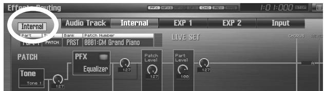
text_image
Effects Routing Internal Audio Track Internal EXP 1 EXP 2 Input Part 1 Bank Patch Number PART 1 PST PRST 0001-CM Grand Piano LIVE SET PATCH PFX Equalizer Tone Tone 1 12.7 12.7 12.7 12.7 12.7 12.7 12.7 12.7 12.7 12.7 12.7 12.7 R| Part Group | Explanation |
| Internal | Internal (internal sound generator) |
| EXP 1 | Expansion board 1 |
| EXP 2 | Expansion board 2 |
| Audio Trk | Audio tracks |
| Input | Audio input |
MEMO
You can switch the part group by holding down [SHIFT] and pressing ◀ or ▶.
Using the pads to switch effects on/off
You can use the pads to directly switch each effect on/off. For the procedure, refer to the following pages.
“11 EFFECT SW (Using the Pads to Switch the Effects)” (p. 199)
"12 PATCH MFX SW (Using the Pads to Switch Patch Multi-effects)" (p. 199)
Making Effect Settings
- In the appropriate mode, select the sound to which you want to apply effects.
- Press [EFFECTS (ROUTING)] to access the Effects screen.
- Press one of the [F1 (Routing)]-[F7 (Mastering)] tabs to select the effect that you want to edit.
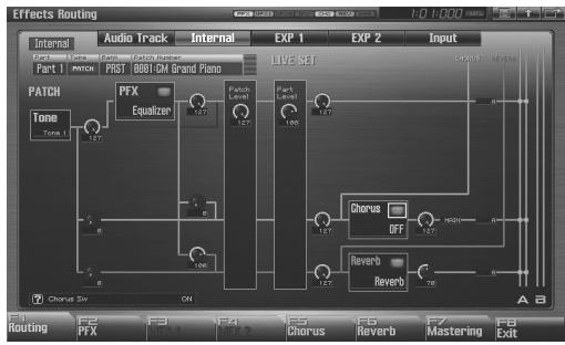
flowchart
graph TD
    A["PART 1"] --> B["PATCH"]
    B --> C["PFX"]
    C --> D["Equalizer"]
    D --> E["Chorus OFF"]
    E --> F["Reverb"]
    F --> G["Chorus Reverb"]
    G --> H["Chorus Mastering"]
    H --> I["Output"]
- Use [CURSOR] to move the cursor to the parameter you wish to modify.
- Turn the VALUE dial or press [INC] [DEC] to get the value you want.
- Press [EXIT] to return to the previous screen.
F-key operations in the effect screen
| F-key | Explanation | Page |
| F1Routing | Routing edit screen | p. 151p. 154 |
| F2PFX | Patch multi-effect edit screen | p. 157 |
| F3MFX 1 | MFX 1 edit screen | p. 158 |
| F4MFX 2 | MFX 2 edit screen | p. 158 |
| F5Chorus | Chorus edit screen | p. 159 |
| F6Reverb | Reverb edit screen | p. 159 |
| F7Mastering | Mastering edit screen | p. 160 |
| F8Exit | Returns to the previous screen | - |
Applying Effects in Single Mode
Single mode allows you to use patch FX (PFX), chorus, and reverb. These effects will operate according to the effect settings of the patch, rhythm set, or sample set that's assigned to the keyboard part.
"Specifying How the Sound will be Output (Routing)" (p. 151)
In addition, you can apply a multi-effect (MFX1) to the external audio input or audio tracks.

"Specifying the effect applied to the external audio input or an audio track" (p. 150)
Applying Effects in Live Mode
Live mode allows you to use patch FX (PFX), chorus, and reverb. These effects will operate according to the effect settings of the live set.
"Specifying How the Sound will be Output (Routing)" (p. 151)
In addition, you can apply a multi-effect (MFX1) to the external audio input or audio tracks.
"Specifying the effect applied to the external audio input or an audio track" (p. 150)
Specifying How the Sound will be Output (Routing)
Here you can make overall settings for effects, and the output destination and level of each signal.
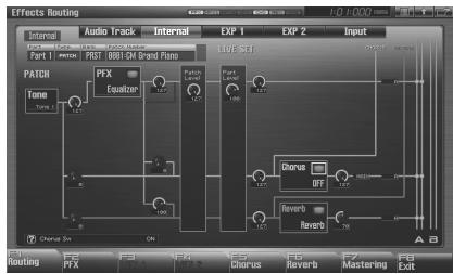
flowchart
graph TD
    A["Tone"] --> B["Chorus"]
    A --> C["Reverb"]
    B --> D["Output"]
    C --> D
    style A fill:#f9f,stroke:#333
    style D fill:#ccf,stroke:#333
For details on these settings, refer to “Making Effect Settings” (p. 151).

In this screen, the name of the parameter selected by the cursor is shown in the “?” area in the lower left of the screen. The current value of the parameter is also shown here.
Signal Flow Diagram and Parameters
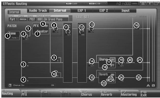
flowchart
graph TD
    A["ONE Tone 1"] --> B["Chorus Sw"]
    C["PFX Equalizer"] --> D["Chorus Sw"]
    E["OFF"] --> F["Reverb"]
    G["LIVE SET"] --> H["Chorus Inlet"]
    I["Chorus Sw"] --> J["ON"]
    K["Chorus Sw"] --> L["ON"]
    M["Chorus Sw"] --> N["ON"]
    O["Chorus Sw"] --> P["ON"]
    Q["Chorus Sw"] --> R["ON"]
    S["Chorus Sw"] --> T["ON"]
    U["Chorus Sw"] --> V["ON"]
    W["Chorus Sw"] --> X["ON"]
    Y["Chorus Sw"] --> Z["ON"]
    AA["Chorus Sw"] --> AB["ON"]
    AC["Chorus Sw"] --> AD["ON"]
    AE["Chorus Sw"] --> AF["ON"]
    AG["Chorus Sw"] --> AH["ON"]
    AI["Chorus Sw"] --> AJ["ON"]
    AK["Chorus Sw"] --> AL["ON"]
    AM["Chorus Sw"] --> AN["ON"]
    AO["Chorus Sw"] --> AP["ON"]
    AQ["Chorus Sw"] --> AR["ON"]
    AS["Chorus Sw"] --> AT["ON"]
    AU["Chorus Sw"] --> AV["ON"]
    AW["Chorus Sw"] --> AX["ON"]
    AY["Chorus Sw"] --> AZ["ON"]
MEMO
In Single mode and Live mode, MFX 1 (multi-effect) will apply only to the external input or to audio tracks, and therefore is now shown in the internal routing diagram.
① Tone Select
Select the tone for which you want to make settings.
Value: ALL, 1–4
MEMO
This parameter is Rhythm Key Select when a rhythm set is being selected. You can select the rhythm tone (A0–C8) for which you want to make settings.
② Tone Output Level
Set the level of the signal that is sent to the output destination specified by Output Assign.
Value: 0–127
③ Tone Chorus Send Level
Sets the level of the signal sent to chorus for each tone.
Value: 0–127
④ Tone Reverb Send Level
Sets the level of the signal sent to reverb for each tone.
Value: 0–127
⑤ Tone Output Assign
Specifies how the direct sound of each tone will be output.
Value:
PFX: Output through patch multi-effects (PFX).
DRY: Output without passing through patch multi-effects (PFX).
⑥ PFX Sw
Switches the patch multi-effect on/off.
Value: ON, OFF
⑦ PFX Type (Patch Multi-Effects Type)
Use this parameter to select from among the 76 available patch multi-effects. For details on patch multi-effects parameters, refer to “MFX/PFX Parameter” (p. 161).
Value: 0 (Through)-76
⑧ PFX Output Level (Patch Multi-Effects Output Level)
Adjusts the volume of the sound that has passed through the patch multi-effects.
Value: 0–127
⑨ PFX Chorus Send Level (Patch Multi-Effects Chorus Send Level)
Adjusts the amount of chorus for the sound that passes through patch multi-effects. If you don't want to add the Chorus effect, set it to "0."
Value: 0–127
⑩ PFX Reverb Send Level (Patch Multi-Effects Reverb Send Level)
Adjusts the amount of reverb for the sound that passes through patch multi-effects. If you don't want to add the Reverb effect, set it to "0."
Value: 0–127
⑪ Patch Level
Adjusts the volume of the patch.
Value: 0–127
12 Part Level
Adjusts the volume of the part.
Value: 0–127
⑬ Part Output Level
Sets the level of the signal sent to the output destination chosen by Part Output Assign.
Value: 0–127
14 Part Chorus Send Level
Sets the level of the signal sent to chorus for each part. If you don't want to add the Chorus effect, set it to "0."
Value: 0–127
15 Part Reverb Send Level
Sets the level of the signal sent to reverb for each part. If you don't want to add the Reverb effect, set it to "0."
Value: 0–127
16 Part Output Assign
Specifies for each part how the direct sound will be output.
Value:
A, B: Output to the OUTPUT A (MIX) jack or OUTPUT B jack in stereo without passing through multi-effects.
1-4: Output to the INDIVIDUAL 1-4 jacks in mono without passing through multi-effects.
NOTE
If you've made settings so that sounds are separately routed to the INDIVIDUAL 1 jack and INDIVIDUAL 2 jack, but no plug is actually inserted in the INDIVIDUAL 2 jack, the sounds routed to INDIVIDUAL 1 and INDIVIDUAL 2 will be mixed and output from the INDIVIDUAL 1 jack.
MEMO
If the Mix/Parallel parameter is set to "MIX," all sounds are output from the OUTPUT A (MIX) jacks in stereo (p. 298).
17 Chorus Sw
Switches the chorus on/off.
Value: ON, OFF
18 Chorus Type
Selects either chorus or delay. For details on chorus parameters, refer to “Chorus Parameters” (p. 184).
Value: 0 (Off)-3 (GM2 Chorus)
19 Chorus Level
Adjusts the volume of the sound that has passed through chorus.
Value: 0–127
20 Chorus Output Select
Specifies how the sound routed through chorus will be output.
Value
MAIN: Output to the OUTPUT jacks in stereo.
REV: Output to reverb in mono.
M+R: Output to the OUTPUT jacks in stereo, and to reverb in mono.
TIP
When set to "MAIN" or "M+R," the OUTPUT jack from which the sound is output is set in Chorus Output Assign.
②1 Chorus Output Assign
Selects the pair of OUTPUT jacks to which the chorus sound is routed when Chorus Output Select is set to "MAIN" or "M+R."
Value
A: Output to the OUTPUT A (MIX) jacks in stereo.
B: Output to the OUTPUT B jacks in stereo.
NOTE
When Chorus Output Select is set to "REV," this setting will have no effect.
MEMO
If the Mix/Parallel parameter is set to "MIX," all sounds are output from the OUTPUT A (MIX) jacks in stereo (p. 298).
22 Reverb Sw
Switches the reverb on/off.
Value: ON, OFF
23 Reverb Type
Selects the type of reverb. For details on reverb parameters, refer to “Reverb Parameters” (p. 185).
Value: 0 (Off)-10 (CHURCH)
24 Reverb Level
Adjusts the volume of the sound that has passed through reverb.
Value: 0–127
25 Reverb Output Assign
Specifies how the sound routed through reverb will be output. Value
A: Output to the OUTPUT A (MIX) jacks in stereo.
B: Output to the OUTPUT B jacks in stereo.
MEMO
If the Mix/Parallel parameter is set to "MIX," all sounds are output from the OUTPUT A (MIX) jacks in stereo (p. 298).
Applying Effects in Studio Mode
Studio mode allows you to use two multi-effects (MFX1, MFX2), one chorus, and one reverb.
These effects will operate according to the effect settings of the studio set.
Specifying How the Sound Will Be Output (Routing)
Here you can make overall settings for effects, and the output destination and level of each signal.
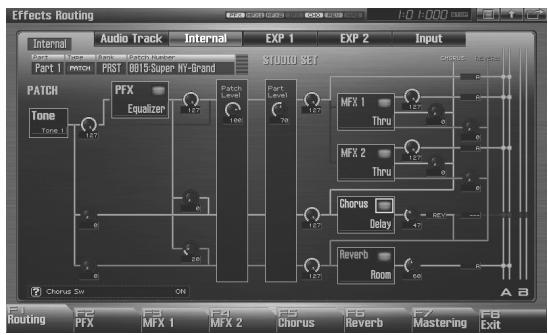
flowchart
graph TD
    A["Audio Track"] --> B["PART 1"]
    B --> C["PFX Equalizer"]
    C --> D["MUXU SET"]
    D --> E["Chorus Delay"]
    E --> F["Reverb Room"]
    F --> G["Chorus Syst"]
    H["Chorus Syst"] --> I["ON"]
    J["Tone Tone 1"] --> K["127"]
    L["Tone"] --> M["127"]
    N["Chorus"] --> O["127"]
    P["Chorus Syst"] --> Q["ON"]
    R["Chorus Syst"] --> S["ON"]
    T["Chorus Syst"] --> U["ON"]
    V["Chorus Syst"] --> W["ON"]
    X["Chorus Syst"] --> Y["ON"]
    Z["Chorus Syst"] --> AA["ON"]
    AB["Chorus Syst"] --> AC["ON"]
    AD["Chorus Syst"] --> AE["ON"]
    AF["Chorus Syst"] --> AG["ON"]
    AH["Chorus Syst"] --> AI["ON"]
    AJ["Chorus Syst"] --> AK["ON"]
    AL["Chorus Syst"] --> AM["ON"]
    AN["Chorus Syst"] --> AO["ON"]
    AP["Chorus Syst"] --> AQ["ON"]
    AR["Chorus Syst"] --> AS["ON"]
    AT["Chorus Syst"] --> AU["ON"]
    AV["Chorus Syst"] --> AW["ON"]
    AX["Chorus Syst"] --> AY["ON"]
    AZ["Chorus Syst"] --> BA["ON"]
    BB["Chorus Syst"] --> BC["ON"]
    BD["Chorus Syst"] --> BE["ON"]
    BF["Chorus Syst"] --> BG["ON"]
    BH["Chorus Syst"] --> BI["ON"]
    BJ["Chorus Syst"] --> BK["ON"]
    BL["Chorus Syst"] --> BM["ON"]
    BN["Chorus Syst"] --> BO["ON"]
    BP["Chorus Syst"] --> BPB["ON"]
    BPB --> BPB1["F6 Reverb"]
    BPB --> BPB2["F7 Mastering"]
    BPB --> BPB3["F8 Exit"]
cf.
For details on these settings, refer to “Making Effect Settings” (p. 151).
MEMO
In this screen, the name of the parameter selected by the cursor is shown in the “?” area in the lower left of the screen. The current value of the parameter is also shown here.
Signal Flow Diagram and Parameters
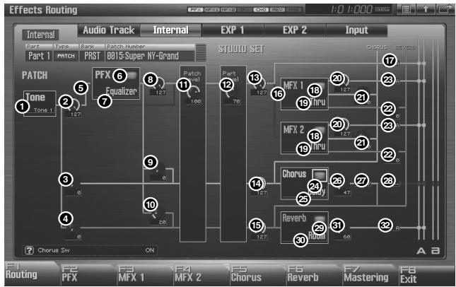
flowchart
graph TD
    A["PART 1"] --> B["TONE 1"]
    B --> C["PATCH 2"]
    C --> D["PRST 0015-Super NY-Grand"]
    D --> E["EXP 1"]
    E --> F["STUDIO SET"]
    F --> G["Chorus"]
    G --> H["Rerverb"]
    H --> I["Round 60"]
    I --> J["Chorus Sw"]
    J --> K["ON"]
    K --> L["Chorus Sw"]
    L --> M["Chorus Sw"]
    M --> N["Chorus Sw"]
    N --> O["Chorus Sw"]
    O --> P["Chorus Sw"]
    P --> Q["Chorus Sw"]
    Q --> R["Chorus Sw"]
    R --> S["Chorus Sw"]
    S --> T["Chorus Sw"]
    T --> U["Chorus Sw"]
    U --> V["Chorus Sw"]
    V --> W["Chorus Sw"]
    W --> X["Chorus Sw"]
    X --> Y["Chorus Sw"]
    Y --> Z["Chorus Sw"]
    Z --> AA["Chorus Sw"]
    AA --> AB["Chorus Sw"]
    AB --> AC["Chorus Sw"]
    AC --> AD["Chorus Sw"]
    AD --> AE["Chorus Sw"]
    AE --> AF["Chorus Sw"]
    AF --> AG["Chorus Sw"]
    AG --> AH["Chorus Sw"]
    AH --> AI["Chorus Sw"]
    AI --> AJ["Chorus Sw"]
    AJ --> AK["Chorus Sw"]
    AK --> AL["Chorus Sw"]
    AL --> AM["Chorus Sw"]
    AM --> AN["Chorus Sw"]
    AN --> AO["Chorus Sw"]
    AO --> AP["Chorus Sw"]
    AP --> AQ["Chorus Sw"]
    AQ --> AR["Chorus Sw"]
    AR --> AS["Chorus Sw"]
    AS --> AT["Chorus Sw"]
    AT --> AU["Chorus Sw"]
    AU --> AV["Chorus Sw"]
    AV --> AW["Chorus Sw"]
    AW --> AX["Chorus Sw"]
    AX --> AY["Chorus Sw"]
    AY --> AZ["Chorus Sw"]
    AZ --> BA["Chorus Sw"]
    BA --> BB["Chorus Sw"]
    BB --> BC["Chorus Sw"]
    BC --> BD["Chorus Sw"]
    BD --> BE["Chorus Sw"]
    BE --> BF["Chorus Sw"]
    BF --> BG["Chorus Sw"]
    BG --> BH["Chorus Sw"]
    BH --> BI["Chorus Sw"]
    BI --> BJ["Chorus Sw"]
    BJ --> BK["Chorus Sw"]
    BK --> BL["Chorus Sw"]
    BL --> BM["Chorus Sw"]
    BM --> BN["Chorus Sw"]
    BN --> BO["Chorus Sw"]
    BO --> BP["Chorus Sw"]
    BP --> BQ["Chorus Sw"]
    BQ --> BR["Chorus Sw"]
    BR --> BS["Chorus Sw"]
    BS --> BT["Chorus Sw"]
    BT --> BU["Chorus Sw"]
    BU --> BV["Chorus Sw"]
    BV --> BW["Chorus Sw"]
    BW --> BX["Chorus Sw"]
    BX --> BY["Chorus Sw"]
    BY --> BZ["Chorus Sw"]
    BZ --> CA["Chorus Sw"]
    CA --> CB["Chorus Sw"]
    CB --> CC["Chorus Sw"]
    CC --> CD["Chorus Sw"]
    CD --> CE["Chorus Sw"]
    CE --> CF["Chorus Sw"]
    CF --> CG["Chorus Sw"]
    CG --> CH["Chorus Sw"]
    CH --> CI["Chorus Sw"]
    CI --> CJ["Chorus Sw"]
    CJ --> CK["Chorus Sw"]
    CK --> CR["Chorus Sw"]
    CR --> CS["Chorus Sw"]
    CS --> CT["Chorus Sw"]
    CT --> CU["Chorus Sw"]
    CU --> CV["Chorus Sw"]
    CV --> CW["Chorus Sw"]
    CW --> CX["Chorus Sw"]
    CX --> CY["Chorus Sw"]
    CY --> CZ["Chorus Sw"]
    CZ --> DA["Chorus Sw"]
    DA --> DB["Chorus Sw"]
    DB --> DC["Chorus Sw"]
    DC --> DD["Chorus Sw"]
    DD --> DE["Chorus Sw"]
    DE --> DF["Chorus Sw"]
    DF --> DG["Chorus Sw"]
    DG --> DH["Chorus Sw"]
    DH --> DI["Chorus Sw"]
    DI --> DJ["Chorus Sw"]
    DJ --> DK["Chorus Sw"]
    DK --> DL["Chorus Sw"]
    DL --> DV["Chorus Sw"]
    DV --> DW["Chorus Sw"]
    DW --> DX["Chorus Sw"]
    DX --> DXB["Chorus Sw"]
① Tone Select
Select the tone for which you want to make settings.
Value: ALL, 1–4
MEMO
This parameter is Rhythm Key Select when a rhythm set is being selected. You can select the rhythm tone (A0–C8) for which you want to make settings.
② Tone Output Level
Set the level of the signal that is sent to the output destination specified by Output Assign.
Value: 0–127
③ Tone Chorus Send Level
Sets the level of the signal sent to chorus for each tone.
Value: 0–127
④ Tone Reverb Send Level
Sets the level of the signal sent to reverb for each tone.
Value: 0–127
⑤ Tone Output Assign
Specifies how the direct sound of each tone will be output.
Value:
PFX: Output through patch multi-effects (PFX).
DRY: Output without passing through patch multi-effects (PFX).
⑥ PFX Sw (Patch Multi-Effects Switch)
Switches the patch multi-effect on/off.
Value: ON, OFF
⑦ PFX Type (Patch Multi-Effects Type)
Use this parameter to select from among the 76 available patch multi-effects. For details on patch multi-effects parameters, refer to “MFX/PFX Parameter” (p. 161).
Value: 0 (Through)-76
⑧ PFX Output Level (Patch Multi-Effects Output Level)
Adjusts the volume of the sound that has passed through the patch multi-effects.
Value: 0–127
⑨ PFX Chorus Send Level (Patch Multi-Effects Chorus Send Level)
Adjusts the amount of chorus for the sound that passes through patch multi-effects. If you don't want to add the Chorus effect, set it to "0."
Value: 0–127
10 PFX Reverb Send Level (Patch Multi-Effects Reverb Send Level)
Adjusts the amount of reverb for the sound that passes through patch multi-effects. If you don't want to add the Reverb effect, set it to "0."
Value: 0–127
⑪ Patch Level
Adjusts the volume of the patch.
Value: 0–127
12 Part Level
Adjusts the volume of the part.
Value: 0–127
⑬ Part Output Level
Sets the level of the signal sent to the output destination chosen by Part Output Assign.
Value: 0–127
14 Part Chorus Send Level
Sets the level of the signal sent to chorus for each part. If you don't want to add the Chorus effect, set it to "0."
Value: 0–127
15 Part Reverb Send Level
Sets the level of the signal sent to reverb for each part. If you don't want to add the Reverb effect, set it to "0."
Value: 0–127
16 Part MFX Select
Specifies whether MFX will not be used, or which of the two multi-effects will be used.
Value: DRY, MFX-1–MFX-2
⑰ Part Output Assign
Specifies how the original sound will be output for each part. This is available only if Part MFX Select is set to DRY.
Value:
A, B: Output to the OUTPUT A (MIX) jack or OUTPUT B jack in stereo without passing through multi-effects.
1-4: Output to the INDIVIDUAL 1-4 jacks in mono without passing through multi-effects.
NOTE
If you've made settings so that sounds are separately routed to the INDIVIDUAL 1 jack and INDIVIDUAL 2 jack, but no plug is actually inserted in the INDIVIDUAL 2 jack, the sounds routed to INDIVIDUAL 1 and INDIVIDUAL 2 will be mixed and output from the INDIVIDUAL 1 jack.
MEMO
If the Mix/Parallel parameter is set to "MIX," all sounds are output from the OUTPUT A (MIX) jacks in stereo (p. 298).
18 MFX Sw (Multi-Effects Switch)
Switches the multi-effect on/off.
Value: ON, OFF
19 MFX Type (Multi-Effects Type)
Use this parameter to select from among the 78 available multi-effects. For details on multi-effects parameters, refer to “MFX/PFX Parameter” (p. 161).
Value: 0 (Through)-78
20 MFX Output Level (Multi-Effects Output Level)
Adjusts the volume of the sound that has passed through the multi-effects.
Value: 0–127
21 MFX Chorus Send Level (Multi-Effects Chorus Send Level)
Adjusts the amount of chorus for the sound that passes through multi-effects. If you don't want to add the Chorus effect, set it to "0."
Value: 0–127
22 MFX Reverb Send Level (Multi-Effects Reverb Send Level)
Adjusts the amount of reverb for the sound that passes through multi-effects. If you don't want to add the Reverb effect, set it to "0."
Value: 0–127
23 MFX Output Assign (Multi-Effects Output Assign)
Adjusts the output destination of the sound that has passed through the multi-effects.
Value
A: Output to the OUTPUT A (MIX) jacks in stereo.
B: Output to the OUTPUT B jacks in stereo.
MEMO
If the Mix/Parallel parameter is set to "MIX," all sounds are output from the OUTPUT A (MIX) jacks in stereo (p. 298).
24 Chorus Sw
Switches the chorus on/off.
Value: ON, OFF
25 Chorus Type
Selects either chorus or delay. For details on chorus parameters, refer to “Chorus Parameters” (p. 184).
Value: 0 (Off)-3 (GM2 Chorus)
26 Chorus Level
Adjusts the volume of the sound that has passed through chorus.
Value: 0–127
27 Chorus Output Select
Specifies how the sound routed through chorus will be output.
Value
MAIN: Output to the OUTPUT jacks in stereo.
REV: Output to reverb in mono.
M+R: Output to the OUTPUT jacks in stereo, and to reverb in mono.
TIP
When set to "MAIN" or "M+R," the OUTPUT jack from which the sound is output is set in Chorus Output Assign.
28 Chorus Output Assign
Selects the pair of OUTPUT jacks to which the chorus sound is routed when Chorus Output Select is set to "MAIN" or "M+R."
Value
A: Output to the OUTPUT A (MIX) jacks in stereo.
B: Output to the OUTPUT B jacks in stereo.
NOTE
When Chorus Output Select is set to "REV," this setting will have no effect.
MEMO
If the Mix/Parallel parameter is set to "MIX," all sounds are output from the OUTPUT A (MIX) jacks in stereo (p. 298).
29 Reverb Sw
Switches the reverb on/off.
Value: ON, OFF
30 Reverb Type
Selects the type of reverb. For details on reverb parameters, refer to “Reverb Parameters” (p. 185).
Value: 0 (Off)-10 (CHURCH)
31 Reverb Level
Adjusts the volume of the sound that has passed through reverb.
Value: 0–127
32 Reverb Output Assign
Specifies how the sound routed through reverb will be output.
Value
A: Output to the OUTPUT A (MIX) jacks in stereo.
B: Output to the OUTPUT B jacks in stereo.
MEMO
If the Mix/Parallel parameter is set to "MIX," all sounds are output from the OUTPUT A (MIX) jacks in stereo (p. 298).
Making Patch Multi-Effects Settings (PFX)
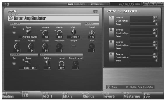
text_image
PFX PFX Control 39 Guitar Amp Simulator* PPE Amp Sw Type Volume Master Gain Output CLEAN TWIN 80 100 MIDDLE 127 Bass Middle Treble Presence Bright Pan 64 64 64 0 0 Simulation Min Sw Type Setting Level Direct Level BUILT-IN 1 2 127 0 Type 39 Guitar Amp Simulator F1 Routing F2 PFX F3 MFX 1 F4 MFX 2 F5 Chorus F6 Reverb F7 Mastering F8 Exitcf.
For details on these settings, refer to “Making Effect Settings” (p. 151)
PFX (Patch Multi-Effects)
Type (Patch Multi-Effects Type)
Use this parameter to select from among the 76 available patch multi-effects. For details on patch multi-effects parameters, refer to “MFX/PFX Parameter” (p. 161).
Value: 00: Thru-76
In this setting screen, you can edit the parameters of the patch multi-effects that is selected by the Patch Multi-effects Type setting. For details on the parameters that can be edited, refer to “MFX/PFX Parameter” (p. 161).
TIP
Patch multi-effect settings allow you to use the Realtime Control knobs to edit up to four pre-specified parameters for each type of patch multi-effect.
MEMO
Parameters marked by ☐ can be selected as a patch multi-effect control destination parameter (p. 157).
PFX Control
Source 1-4 (Multi-Effects Control Source 1-4)
Sets the MIDI message used to change the multi-effects parameter with the multi-effects control.
Value
OFF: Multi-effects control will not be used.
CC01-31, CC32(OFF), 33-95:
Control Change
PITCH BEND: Pitch Bend
AFTERTOUCH: Aftertouch
SYS CTRL1–SYS CTRL4: MIDI messages used as common multi-effects controls.
TIP
If you want to use common controllers for the entire Fantom-G, select "SYS CTRL 1"–"SYS CTRL 4." MIDI messages used as System Control 1–4 are set with the Sys Ctrl 1–4 Source parameters (p. 301).
NOTE
In patch/rhythm set/sample set, there are parameters that determine, for each tone/rhythm tone, whether or not Pitch Bend, Controller Number 11 (Expression) and Controller Number 64 (Hold 1) are received (p. 108). When these settings are “ON,” and the MIDI messages are received, then when any change is made in the settings of the desired parameter, the Pitch Bend, Expression, and Hold1 settings also change simultaneously. If you want to change the targeted parameters only, then set these to “OFF.”
- Live mode and Studio mode provide parameters that let you specify whether specific MIDI messages will be received for each MIDI channel. When using multi-effect control, make sure that reception is enabled for the MIDI messages you're using. If MIDI message reception is disabled, multi-effect control won't work.
Destination 1-4 (Multi-Effects Control Destination 1-4)
Sets the multi-effects parameters to be controlled with the multi-effects control. The multi-effects parameters available for control will depend on the multi-effects type. For details, refer to “MFX/PFX
Parameter" (p. 161).
Sens 1-4 (Multi-Effects Control Sensitivity 1-4)
Sets the amount of the multi-effects control's effect that is applied. To make an increase in the currently selected value (to get higher values, move to the right, increase rates, and so on), select a positive value; to make a decrease in the currently selected value (to get lower values, move to the left, decrease rates, and so on), select a negative value. For either positive or negative settings, greater absolute values will allow greater amounts of change. Set this to "0" if you don't want to apply the effect.
Value: -63- +63
Multi-Effects Control
If you wanted to change the volume of multi-effects sounds, the delay time of Delay, and the like, using an external MIDI device, you would need to send System Exclusive messages-MIDI messages designed exclusively for the Fantom-G. However, System Exclusive messages tend to be complicated, and the amount of data that needs to be transmitted can get quite large. For that reason, a number of the more typical of the Fantom-G's multi-effects parameters have been designed so they accept the use of Control Change (or other) MIDI messages for the purpose of making changes in their values. For example, you can use the Pitch Bend lever to change the amount of distortion, or use the keyboard's touch to change the delay time of Delay. The parameters that can be changed are predetermined for each type of multi-effect; among the parameters described in “MFX/PFX Parameter” (p. 161), these are indicated by a “#.”
In the multi-effect setting screen, a "c" symbol will be shown at the left of the parameter.
The function that allows you use MIDI messages to make these changes in realtime to the multi-effects parameters is called the Multi-effects Control. Up to four multi-effects controls can be used in a single patch/rhythm set/sample set/live set/studio set.
When the multi-effects control is used, you can select the amount of control (Sens parameter) applied, the parameter selected (Destination parameter), and the MIDI message used (Source parameter).
TIP
By using the Matrix Control instead of the Multi-effects Control, you can also change the parameters of some popular multi-effects in realtime (p. 109).
Making Multi-Effects Settings (MFX1-2)
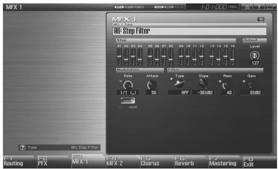
text_image
MFX 1 MFX 1 Type MFX 1 06-Step Filter Step Output Level 127 Modulation Filter Rate Attack Type Slope Reso Gain 1/1 (A) 50 HPF +36(8B) 40 0(8B) NOTE Type MFX Step Filter F1 Routing F2 PFX MFX 1 F3 MFX 2 F4 Chorus F5 Reverb F6 Mastering F7 Exitcf.
For details on these settings, refer to “Making Effect Settings” (p. 151)
Type (Multi-Effects Type)
Use this parameter to select from among the 78 available multi-effects. For details on multi-effects parameters, refer to “MFX/PFX Parameter” (p. 161).
Value: 00: Thru-78
In this setting screen, you can edit the parameters of the multi-effects that is selected by the Multi-effects Type setting. For details on the parameters that can be edited, refer to “MFX/PFX Parameter” (p. 161).
TIP
Multi-effect settings allow you to use the Realtime Control knobs to edit up to four pre-specified parameters for each multi-effect type.
Making Chorus Settings (Chorus)
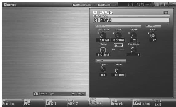
text_image
Chorus Chorus Type 81 Chorus Chorus Pre Delay Rate Depth Output Level 2.0ms1 0.50Hzcl 20 47 Phase Feedback 180deg1 0 Filter Type Cutoff HPF 800Hzcl F1 Routing F2 PFX F3 MFX 1 F4 MFX 2 F5 Chorus F6 Reverb F7 Mastering F8 Exit
For details on these settings, refer to “Making Effect Settings” (p. 151)
Type (Chorus Type)
Selects either chorus or delay. For details on chorus parameters, refer to “Chorus Parameters” (p. 184).
Value: 00: OFF-03: GM2 Chorus
* In this setting screen, you can edit the parameters of the chorus/delay that is selected by the Chorus Type setting. For details on the parameters that can be edited, refer to “Chorus Parameters” (p. 184).

If a number (1-4) is shown for a parameter in the screen, you can use the corresponding Realtime Control knob (far left knob is 1-far right knob is 4) to adjust the value of that parameter.
Making Reverb Settings (Reverb)
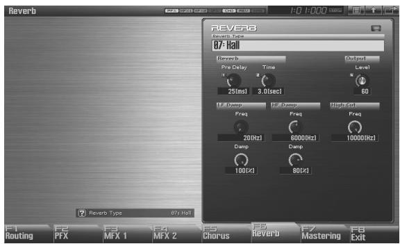
text_image
Reverb Reverb Type 07 Hall Reverb Pre Delay Time 25ms/3.0sec/1 Output Level 60 LF Delay Full Delay Single Freq Freq Freq 200Hz 6000Hz 10000Hz Damp Damp 100Hz 80Hz F1 F2 F3 F4 F5 F6 F7 F8 Routing PFX MFX 1 MFX 2 Chorus Reverb Mastering F8 Exit Reverb Type 07 Hall
For details on these settings, refer to “Making Effect Settings” (p. 151)
Type (Reverb Type)
Selects the type of reverb. For details on reverb parameters, refer to “Reverb Parameters” (p. 185).
Value: 00: OFF-10: Church
* In this setting screen, you can edit the parameters of the reverb that is selected by the Reverb Type setting. For details on the parameters that can be edited, refer to “Reverb Parameters” (p. 185).

If a number (1 - 4) is shown for a parameter in the screen, you can use the corresponding Realtime Control knob (far left knob is 4 - far right knob is 4) to adjust the value of that parameter.
Mastering Effect
This is a stereo compressor (limiter) that is applied to the final output of the Fantom-G. It has independent high, mid, and low ranges. Independently for the high-frequency, mid-frequency, and low-frequency regions, this compresses any sounds that exceed the specified level, making the volume more consistent. When mixing down to MD, or DAT, or when you procedure your own original audio CD, this lets you master at an optimized level.
* Mastering effect settings apply to the entire Fantom-G. These settings are not for individual patches or performances.
* The mastering effect is applied to the sound that is output from the OUTPUT A (MIX) jacks. It will not be applied to the sound that is output from the OUTPUT B jacks.
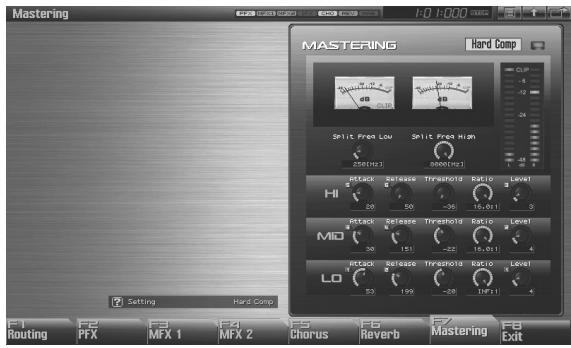
text_image
Mastering Mastering Hand Comp CLP -4 -12 -24 Split From Low Split From High 250(Hz) 250(Hz) Hi 20 50 -36 15, 2011 MIO 30 151 -32 15, 2011 LO 55 199 -28 19F21 F1 Routing PFX F2 F3 MFX 1 F4 F5 F6 F7 F8 F9 MFX 2 Chorus Reverb Mastering FB Exitcf.
For details on these settings, refer to “Making Effect Settings” (p. 151)
Setting
This recalls settings for the mastering effect.
Value: System (other than Studio Mode),
Studio (only in Studio Mode),
User, Hard Comp, Soft Comp. Low Boost,
Mid Boost, High Boost
MEMO
To save settings for the mastering effect, press the panel [WRITE] button. The settings are saved in the Setting parameter "System" ("Studio" in the case of Studio mode).
The mastering effect settings you save here are saved as system settings in the case of Single mode or Live mode. In the case of Studio mode, they are saved in the studio set.
Attack
Time from when the volume goes up the threshold level until the compressor effect applies
Value: 0–100 ms
Release
Time from when the volume falls below the threshold level until the compressor effect no longer applies
Value: 50–5000 ms
Threshold
Volume level at which compression begins
Value: -36–0 dB
Ratio
Compression ratio
Value: 1.00:1–INF:1 (INF: infinity)
Level
Output volume
Value: 0–24 dB
Split Frequency High
Frequency at which the high-frequency (HI) and mid-frequency (MID) bands are split
Value: 2000–8000 Hz
Split Frequency Low
Frequency at which the low-frequency (LO) and mid-frequency (MID) bands are split
Value: 200–800 Hz
About Threshold and Ratio
As shown in the diagram below, these parameters determine how the volume is to be compressed.
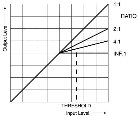
line
| Input Level | Ratio 1 | Ratio 2 | Ratio 4 | Ratio INF | | ----------- | ------- | ------- | ------- | --------- | | < THRESHOLD | 0 | 0 | 0 | 0 | | > THRESHOLD | 1:1 | 2:1 | 4:1 | INF:1 |MFX/PFX Parameter
The MFX (multi-effects) feature 78 different kinds of effects (the PFX: 76 types). Some of the effects consist of two or more different effects connected in series.
Parameters marked with a sharp “#” can be controlled using a specified controller (Two setting items will change simultaneously for “#1” and “#2”).
| FILTER (10 types) | ||
| 01 | EQUALIZER | p. 162 |
| 02 | SPECTRUM | p. 162 |
| 03 | ISOLATOR | p. 162 |
| 04 | LOW BOOST | p. 162 |
| 05 | SUPER FILTER | p. 163 |
| 06 | STEP FILTER | p. 163 |
| 07 | ENHANCER | p. 163 |
| 08 | AUTO WAH | p. 164 |
| 09 | HUMANIZER | p. 164 |
| 10 | SPEAKER SIMULATOR | p. 164 |
| MODULATION (12 types) | ||
| 11 | PHASER | p. 165 |
| 12 | STEP PHASER | p. 165 |
| 13 | MULTI STAGE PHASER | p. 165 |
| 14 | INFINITE PHASER | p. 165 |
| 15 | RING MODULATOR | p. 166 |
| 16 | STEP RING MODULATOR | p. 166 |
| 17 | TREMOLO | p. 166 |
| 18 | AUTO PAN | p. 166 |
| 19 | STEP PAN | p. 166 |
| 20 | SLICER | p. 167 |
| 21 | ROTARY | p. 167 |
| 22 | VK ROTARY | p. 167 |
| CHORUS (12 types) | ||
| 23 | CHORUS | p. 168 |
| 24 | FLANGER | p. 168 |
| 25 | STEP FLANGER | p. 168 |
| 26 | HEXA-CHORUS | p. 169 |
| 27 | TREMOLO CHORUS | p. 169 |
| 28 | SPACE-D | p. 169 |
| 29 | 3D CHORUS | p. 169 |
| 30 | 3D FLANGER | p. 170 |
| 31 | 3D STEP FLANGER | p. 170 |
| 32 | 2BAND CHORUS | p. 170 |
| 33 | 2BAND FLANGER | p. 171 |
| 34 | 2BAND STEP FLANGER | p. 171 |
| DYNAMICS (8 types) | ||
| 35 | OVERDRIVE | p. 172 |
| 36 | DISTORTION | p. 172 |
| 37 | VS OVERDRIVE | p. 172 |
| 38 | VS DISTORTION | p. 172 |
| 39 | GUITAR AMP SIMULATOR | p. 172 |
| 40 | COMPRESSOR | p. 173 |
| 41 | LIMITER | p. 173 |
| 42 | GATE | p. 173 |
| DELAY (13 types) | ||
| 43 | DELAY | p. 173 |
| 44 | LONG DELAY | p. 174 |
| 45 | SERIAL DELAY | p. 174 |
| 46 | MODULATION DELAY | p. 174 |
| 47 | 3TAP PAN DELAY | p. 175 |
| 48 | 4TAP PAN DELAY | p. 175 |
| 49 | MULTI TAP DELAY | p. 175 |
| 50 | REVERSE DELAY | p. 175 |
| 51 | SHUFFLE DELAY | p. 176 |
| 52 | 3D DELAY | p. 176 |
| 53 | TIME CTRL DELAY | p. 176 |
| 54 | LONG TIME CTRL DELAY | p. 177 |
| 55 | TAPE ECHO | p. 177 |
| LO-FI (5 types) | ||
| 56 | LOFI NOISE | p. 177 |
| 57 | LOFI COMPRESS | p. 178 |
| 58 | LOFI RADIO | p. 178 |
| 59 | TELEPHONE | p. 178 |
| 60 | PHONOGRAPH | p. 178 |
| PITCH (3 types) | ||
| 61 | PITCH SHIFTER | p. 179 |
| 62 | 2VOICE PITCH SHIFTER | p. 179 |
| 63 | STEP PITCH SHIFTER | p. 179 |
| COMBINATION (12 types) | ||
| 64 | OVERDRIVE → CHORUS | p. 179 |
| 65 | OVERDRIVE → FLANGER | p. 180 |
| 66 | OVERDRIVE → DELAY | p. 180 |
| 67 | DISTORTION → CHORUS | p. 180 |
| 68 | DISTORTION → FLANGER | p. 180 |
| 69 | DISTORTION → DELAY | p. 180 |
| 70 | ENHANCER → CHORUS | p. 181 |
| 71 | ENHANCER → FLANGER | p. 181 |
| 72 | ENHANCER → DELAY | p. 181 |
| 73 | CHORUS → DELAY | p. 181 |
| 74 | FLANGER → DELAY | p. 182 |
| 75 | CHORUS → FLANGER | p. 182 |
| PIANO (1 type) | ||
| 76 | SYMPATHETIC RESONANCE | p. 182 |
| REVERB (2 types) *MFX only | ||
| 77 | REVERB | p. 183 |
| 78 | GATED REVERB | p. 183 |
About Note
Some effect parameters (such as Rate or Delay Time) can be set in terms of a note value.
Such parameters have a num/note switch that lets you specify whether you will set the value as a note value or as a numerical value.
If you want to set Rate (Delay Time) as a numerical value, set the num/note switch to "Hz" ("msec"). If you want to set it as a note value, set the num/note switch to "NOTE."
NOTE
If a parameter whose num/note switch is set to “NOTE” is specified as a destination for multi-effect control, you will not be able to use multi-effect control to control that parameter.
01: EQUALIZER
This is a four-band stereo equalizer (low, mid x 2, high).
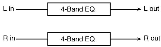
flowchart
graph LR
    A["L in"] --> B["4-Band EQ"]
    C["R in"] --> D["4-Band EQ"]
    B --> D
    E["L out"] --> B
    F["R out"] --> D
| Parameter | Value | Description |
| Low Freq | 200, 400 Hz | Frequency of the low range |
| Low Gain # | -15– +15 dB | Gain of the low range |
| Mid1 Freq | 200–8000 Hz | Frequency of the middle range 1 |
| Mid1 Gain | -15– +15 dB | Gain of the middle range 1 |
| Mid1 Q | 0.5, 1.0, 2.0, 4.0, 8.0 | Width of the middle range 1Set a higher value for Q to narrow the range to be affected. |
| Mid2 Freq | 200–8000 Hz | Frequency of the middle range 2 |
| Mid2 Gain | -15– +15 dB | Gain of the middle range 2 |
| Mid2 Q | 0.5, 1.0, 2.0, 4.0, 8.0 | Width of the middle range 2Set a higher value for Q to narrow the range to be affected. |
| High Freq | 2000, 4000, 8000 Hz | Frequency of the high range |
| High Gain # | -15– +15 dB | Gain of the high range |
| Level # | 0–127 | Output Level |
02: SPECTRUM
This is a stereo spectrum. Spectrum is a type of filter which modifies the timbre by boosting or cutting the level at specific frequencies.
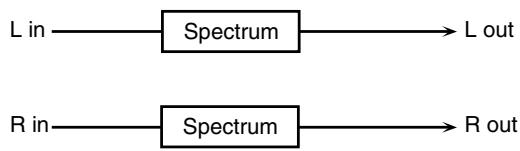
flowchart
graph LR
    A["L in"] --> B["Spectrum"] --> C["L out"]
    D["R in"] --> E["Spectrum"] --> F["R out"]
| Parameter | Value | Description |
| Band1 (250Hz) | -15– +15 dB | Gain of each frequency band |
| Band2 (500Hz) | ||
| Band3 (1000Hz) | ||
| Band4 (1250Hz) | ||
| Band5 (2000Hz) | ||
| Band6 (3150Hz) | ||
| Band7 (4000Hz) | ||
| Band8 (8000Hz) | ||
| Q | 0.5, 1.0, 2.0, 4.0, 8.0 | Simultaneously adjusts the width of the adjusted ranges for all the frequency bands. |
| Level # | 0–127 | Output Level |
03: ISOLATOR
This is an equalizer which cuts the volume greatly, allowing you to add a special effect to the sound by cutting the volume in varying ranges.
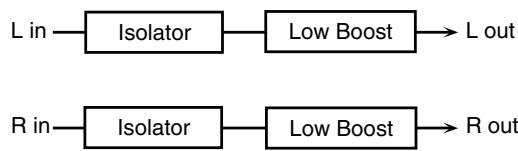
flowchart
graph LR
    A["L in"] --> B["Isolator"]
    B --> C["Low Boost"]
    C --> D["L out"]
    E["R in"] --> F["Isolator"]
    F --> G["Low Boost"]
    G --> H["R out"]
| Parameter | Value | Description |
| Boost/Cut Low # | -60–+4 dB | These boost and cut each of the High, Middle, and Low frequency ranges.At -60 dB, the sound becomes in-audible. 0 dB is equivalent to the input level of the sound. |
| Boost/Cut Mid # | ||
| Boost/Cut High # | ||
| Anti PhaseLow Sw | OFF, ON | Turns the Anti-Phase function on and off for the Low frequency ranges.When turned on, the counter-channel of stereo sound is inverted and added to the signal. |
| Anti PhaseLow Level | 0–127 | Adjusts the level settings for the Low frequency ranges.Adjusting this level for certain frequencies allows you to lend emphasis to specific parts. (This is effective only for stereo source.) |
| Anti PhaseMid Sw | OFF, ON | Settings of the Anti-Phase function for the Middle frequency rangesThe parameters are the same as for the Low frequency ranges. |
| Anti PhaseMid Level | 0–127 | |
| Low Boost Sw | OFF, ON | Turns Low Booster on/off.This emphasizes the bottom to create a heavy bass sound. |
| Low BoostLevel | 0–127 | Increasing this value gives you a heavier low end.* Depending on the Isolator and filter settings this effect may be hard to distinguish. |
| Level | 0–127 | Output Level |
04: LOW BOOST
Boosts the volume of the lower range, creating powerful lows.
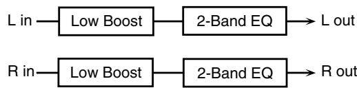
flowchart
graph LR
    A["L in"] --> B["Low Boost"]
    B --> C["2-Band EQ"]
    C --> D["L out"]
    E["R in"] --> F["Low Boost"]
    F --> G["2-Band EQ"]
    G --> H["R out"]
| Parameter | Value | Description |
| Boost Frequency # | 50–125 Hz | Center frequency at which the lower range will be boosted |
| Boost Gain # | 0– +12 dB | Amount by which the lower range will be boosted |
| Boost Width | WIDE, MID, NARROW | Width of the lower range that will be boosted |
| Low Gain | -15– +15 dB | Gain of the low frequency range |
| High Gain | -15– +15 dB | Gain of the high frequency range |
| Level | 0–127 | Output level |
05: SUPER FILTER
This is a filter with an extremely sharp slope. The cutoff frequency can be varied cyclically.
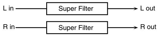
flowchart
graph LR
    A["L in"] --> B["Super Filter"]
    C["R in"] --> D["Super Filter"]
    B --> D
    E["L out"] --> D
    F["R out"] --> D
| Parameter | Value | Description |
| Filter Type | LPF, BPF,HPF, NOTCH | Filter typeFrequency range that will pass through each filterLPF: frequencies below the cutoffBPF: frequencies in the region of the cutoffHPF: frequencies above the cutoffNOTCH: frequencies other than the region of the cutoff |
| Filter Slope | -12, -24, -36 dB | Amount of attenuation per octave-36 dB: extremely steep-24 dB: steep-12 dB: gentle |
| Filter Cutoff # | 0–127 | Cutoff frequency of the filterIncreasing this value will raise the cutoff frequency. |
| Filter Resonance # | 0–127 | Filter resonance levelIncreasing this value will emphasize the region near the cutoff frequency. |
| Filter Gain | 0– +12 dB | Amount of boost for the filter output |
| Modulation Sw | OFF,ON | On/off switch for cyclic change |
| Modulation Wave | TRI, SQR,SIN, SAW1,SAW2 | How the cutoff frequency will be mod-ulatedTRI: triangle waveSQR: square waveSIN: sine waveSAW1: sawtooth wave (upward)SAW2: sawtooth wave (downward) |
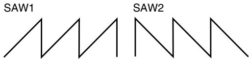 | ||
| Rate # | 0.05–10.00 Hz, note | Rate of modulation |
| Depth | 0–127 | Depth of modulation |
| Attack # | 0–127 | Speed at which the cutoff frequency will changeThis is effective if Modulation Wave is SQR, SAW1, or SAW2. |
| Level | 0–127 | Output level |
06: STEP FILTER
This is a filter whose cutoff frequency can be modulated in steps. You can specify the pattern by which the cutoff frequency will change.
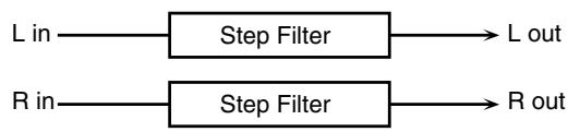
flowchart
graph LR
    A["L in"] --> B["Step Filter"]
    C["R in"] --> D["Step Filter"]
    B --> E["L out"]
    D --> F["R out"]
| Parameter | Value | Description |
| Step 01-16 | 0-127 | Cutoff frequency at each step |
| Rate # | 0.05-10.00 Hz, note | Rate of modulation |
| Attack # | 0-127 | Speed at which the cutoff frequency changes between steps |
| Filter Type | LPF, BPF, HPF, NOTCH | Filter typeFrequency range that will pass through each filterLPF: frequencies below the cutoffBPF: frequencies in the region of the cutoffHPF: frequencies above the cutoffNOTCH: frequencies other than the region of the cutoff |
| Filter Slope | -12, -24, -36 dB | Amount of attenuation per octave-12 dB: gentle-24 dB: steep-36 dB: extremely steep |
| Filter Resonance # | 0-127 | Filter resonance levelIncreasing this value will emphasize the region near the cutoff frequency. |
| Filter Gain | 0- +12 dB | Amount of boost for the filter output |
| Level | 0-127 | Output level |
07: ENHANCER
Controls the overtone structure of the high frequencies, adding sparkle and tightness to the sound.
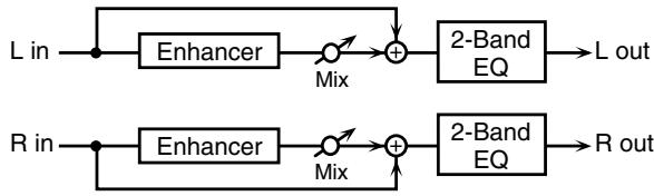
flowchart
graph LR
    A["L in"] --> B["Enhancer"]
    B --> C["Mix"]
    C --> D["+"]
    D --> E["2-Band EQ"]
    E --> F["L out"]
    G["R in"] --> H["Enhancer"]
    H --> I["Mix"]
    I --> J["+"]
    J --> K["2-Band EQ"]
    K --> L["R out"]
| Parameter | Value | Description |
| Sens # | 0–127 | Sensitivity of the enhancer |
| Mix # | 0–127 | Level of the overtones generated by the enhancer |
| Low Gain | -15– +15 dB | Gain of the low range |
| High Gain | -15– +15 dB | Gain of the high range |
| Level | 0–127 | Output Level |
08: AUTO WAH
Cyclically controls a filter to create cyclic change in timbre.
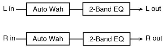
flowchart
graph LR
    A["L in"] --> B["Auto Wah"]
    B --> C["2-Band EQ"]
    C --> D["L out"]
    E["R in"] --> F["Auto Wah"]
    F --> G["2-Band EQ"]
    G --> H["R out"]
| Parameter | Value | Description |
| Filter Type | LPF, BPF | Type of filterLPF: The wah effect will be applied over a wide frequency range.BPF: The wah effect will be applied over a narrow frequency range. |
| Manual # | 0–127 | Adjusts the center frequency at which the effect is applied. |
| Peak | 0–127 | Adjusts the amount of the wah effect that will occur in the range of the center frequency.Set a higher value for Q to narrow the range to be affected. |
| Sens # | 0–127 | Adjusts the sensitivity with which the filter is controlled. |
| Polarity | UP, DOWN | Sets the direction in which the frequency will change when the auto-wah filter is modulated.UP: The filter will change toward a higher frequency.DOWN: The filter will change toward a lower frequency. |
| Rate # | 0.05–10.00 Hz, note | Frequency of modulation |
| Depth # | 0–127 | Depth of modulation |
| Phase # | 0–180 deg | Adjusts the degree of phase shift of the left and right sounds when the wah effect is applied. |
| Low Gain | -15– +15 dB | Gain of the low range |
| High Gain | -15– +15 dB | Gain of the high range |
| Level | 0–127 | Output Level |
09: HUMANIZER
Adds a vowel character to the sound, making it similar to a human voice.

flowchart
graph LR
    A["L in"] --> C["+"]
    B["R in"] --> C
    C --> D["Overdrive"]
    D --> E["Formant"]
    E --> F["2-Band EQ"]
    F --> G["L out"]
    F --> H["Pan L"]
    F --> I["Pan R"]
    F --> J["R out"]
| Parameter | Value | Description |
| Drive Sw | OFF, ON | Turns Drive on/off. |
| Drive # | 0–127 | Degree of distortionAlso changes the volume. |
| Vowel1 | a, e, i, o, u | Selects the vowel. |
| Vowel2 | a, e, i, o, u | |
| Rate # | 0.05–10.00 Hz, note | Frequency at which the two vowels switch |
| Depth # | 0–127 | Effect depth |
| Input Sync Sw | OFF, ON | Determines whether the LFO for switching the vowels is reset by the input signal (ON) or not (OFF). |
| Input Sync Threshold | 0–127 | Volume level at which reset is applied |
| Manual # | 0–100 | Point at which Vowel 1/2 switch49 or less: Vowel 1 will have a longer duration.50: Vowel 1 and 2 will be of equal duration.51 or more: Vowel 2 will have a longer duration. |
| Low Gain | -15– +15 dB | Gain of the low frequency range |
| High Gain | -15– +15 dB | Gain of the high frequency range |
| Pan # | L64–63R | Stereo location of the output |
| Level | 0–127 | Output level |
10: SPEAKER SIMULATOR
Simulates the speaker type and mic settings used to record the speaker sound.
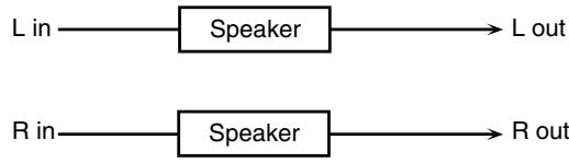
flowchart
graph LR
    A["L in"] --> B["Speaker"]
    C["R in"] --> D["Speaker"]
    B --> E["L out"]
    D --> F["R out"]
| Parameter | Value | Description |
| Speaker Type | (See “Specifications of each Speaker Type”) | Type of speaker |
| Mic Setting | 1, 2, 3 | Adjusts the location of the mic that is recording the sound of the speaker.This can be adjusted in three steps, with the mic becoming more distant in the order of 1, 2, and 3. |
| Mic Level # | 0–127 | Volume of the microphone |
| Direct Level # | 0–127 | Volume of the direct sound |
| Level # | 0–127 | Output Level |
Specifications of each Speaker Type
The speaker column indicates the diameter of each speaker unit (in inches) and the number of units.
| Type | Cabinet | Speaker | Micro-phone |
| SMALL 1 | small open-back enclosure | 10 | dynamic |
| SMALL 2 | small open-back enclosure | 10 | dynamic |
| MIDDLE | open back enclosure | 12 × 1 | dynamic |
| JC-120 | open back enclosure | 12 × 2 | dynamic |
| BUILT-IN 1 | open back enclosure | 12 × 2 | dynamic |
| BUILT-IN 2 | open back enclosure | 12 × 2 | condenser |
| BUILT-IN 3 | open back enclosure | 12 × 2 | condenser |
| BUILT-IN 4 | open back enclosure | 12 × 2 | condenser |
| BUILT-IN 5 | open back enclosure | 12 × 2 | condenser |
| BG STACK 1 | sealed enclosure | 12 × 2 | condenser |
| BG STACK 2 | large sealed enclosure | 12 × 2 | condenser |
| MS STACK 1 | large sealed enclosure | 12 × 4 | condenser |
| MS STACK 2 | large sealed enclosure | 12 × 4 | condenser |
| METAL STACK | large double stack | 12 × 4 | condenser |
| 2-STACK | large double stack | 12 × 4 | condenser |
| 3-STACK | large triple stack | 12 × 4 | condenser |
11: PHASER
A phase-shifted sound is added to the original sound and modulated.
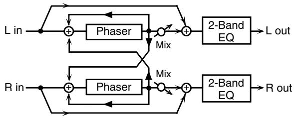
flowchart
graph TD
    A["L in"] --> B["+"]
    B --> C["Phaser"]
    C --> D["Mix"]
    D --> E["+"]
    E --> F["2-Band EQ"]
    F --> G["L out"]
    H["R in"] --> I["+"]
    I --> J["Phaser"]
    J --> K["Mix"]
    K --> L["+"]
    L --> M["2-Band EQ"]
    M --> N["R out"]
    B --> O["+"]
    O --> P["Mix"]
    P --> Q["+"]
    Q --> R["2-Band EQ"]
    R --> S["R out"]
| Parameter | Value | Description |
| Mode | 4-STAGE, 8-STAGE, 12-STAGE | Number of stages in the phaser |
| Manual # | 0-127 | Adjusts the basic frequency from which the sound will be modu-lated. |
| Rate # | 0.05-10.00 Hz, note | Frequency of modulation |
| Depth | 0-127 | Depth of modulation |
| Polarity | INVERSE, SYNCHRO | Selects whether the left and right phase of the modulation will be the same or the opposite.INVERSE: The left and right phase will be opposite. When using a mono source, this spreads the sound.SYNCHRO: The left and right phase will be the same. Select this when inputting a stereo source. |
| Resonance # | 0-127 | Amount of feedback |
| Cross Feedback | -98- +98 % | Adjusts the proportion of the phaser sound that is fed back into the effect. Negative (-) set-tings will invert the phase. |
| Mix # | 0-127 | Level of the phase-shifted sound |
| Low Gain | -15- +15 dB | Gain of the low range |
| High Gain | -15- +15 dB | Gain of the high range |
| Level | 0-127 | Output Level |
12: STEP PHASER
The phaser effect will be varied gradually.
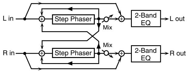
flowchart
graph TD
    A["L in"] --> B["+"]
    B --> C["Step Phaser"]
    C --> D["+"]
    D --> E["2-Band EQ"]
    E --> F["L out"]
    G["R in"] --> H["+"]
    H --> I["Step Phaser"]
    I --> J["+"]
    J --> K["2-Band EQ"]
    K --> L["R out"]
    B --> M["Mix"]
    I --> N["Mix"]
    M --> D
    N --> J
| Parameter | Value | Description |
| Mode | 4-STAGE, 8-STAGE, 12-STAGE | Number of stages in the phaser |
| Manual # | 0-127 | Adjusts the basic frequency from which the sound will be modu-lated. |
| Rate # | 0.05-10.00 Hz, note | Frequency of modulation |
| Depth | 0-127 | Depth of modulation |
| Polarity | INVERSE, SYNCHRO | Selects whether the left and right phase of the modulation will be the same or the opposite.INVERSE:The left and right phase will be opposite. When using a mono source, this spreads the sound.SYNCHRO:The left and right phase will be the same. Select this when inputting a stereo source. |
| Resonance # | 0-127 | Amount of feedback |
| Parameter | Value | Description |
| Cross Feedback | -98–+98 % | Adjusts the proportion of the phaser sound that is fed back into the effect. Negative (-) settings will invert the phase. |
| Step Rate # | 0.10–20.00 Hz, note | Rate of the step-wise change in the phaser effect |
| Mix # | 0–127 | Level of the phase-shifted sound |
| Low Gain | -15–+15 dB | Gain of the low range |
| High Gain | -15–+15 dB | Gain of the high range |
| Level | 0–127 | Output Level |
13: MULTI STAGE PHASER
Extremely high settings of the phase difference produce a deep phaser effect.
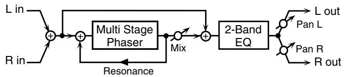
flowchart
graph LR
    A["L in"] --> B["+"]
    C["R in"] --> B
    B --> D["+"]
    E["Resonance"] --> D
    D --> F["Multi Stage Phaser"]
    F --> G["Mix"]
    G --> H["+"]
    I["2-Band EQ"] --> J["L out"]
    I --> K["Pan L"]
    I --> L["Pan R"]
    I --> M["R out"]
| Parameter | Value | Description |
| Mode | 4-STAGE, 8-STAGE,12-STAGE, 16-STAGE, 20-STAGE, 24-STAGE | Number of phaser stages |
| Manual # | 0–127 | Adjusts the basic frequency from which the sound will be modu-lated. |
| Rate # | 0.05–10.00 Hz, note | Frequency of modulation |
| Depth | 0–127 | Depth of modulation |
| Resonance # | 0–127 | Amount of feedback |
| Mix # | 0–127 | Level of the phase-shifted sound |
| Pan # | L64–63R | Stereo location of the output sound |
| Low Gain | -15– +15 dB | Gain of the low range |
| High Gain | -15– +15 dB | Gain of the high range |
| Level | 0–127 | Output Level |
14: INFINITE PHASER
A phaser that continues raising/lowering the frequency at which the sound is modulated.

flowchart
graph LR
    A["L in"] --> C["+"]
    B["R in"] --> C
    C --> D["Infinite Phaser"]
    D --> E["2-Band EQ"]
    E --> F["L out"]
    E --> G["Pan L"]
    E --> H["Pan R"]
    E --> I["R out"]
| Parameter | Range | Explanation |
| Mode | 1, 2, 3, 4 | Higher values will produce a deeper phaser effect. |
| Speed # | -100– +100 | Speed at which to raise or lower the frequency at which the sound is modulated(+: upward / -: downward) |
| Resonance # | 0–127 | Amount of feedback |
| Mix # | 0–127 | Volume of the phase-shifted sound |
| Pan # | L64–63R | Panning of the output sound |
| Low Gain | -15– +15 dB | Amount of boost/cut for the low-frequency range |
| High Gain | -15– +15 dB | Amount of boost/cut for the high-frequency range |
| Level | 0–127 | Output volume |
15: RING MODULATOR
This is an effect that applies amplitude modulation (AM) to the input signal, producing bell-like sounds. You can also change the modulation frequency in response to changes in the volume of the sound sent into the effect.

flowchart
graph LR
    A["L in"] --> B["Ring Mod"]
    B --> C["2-Band EQ"]
    C --> D["L out"]
    E["R in"] --> F["Ring Mod"]
    F --> G["2-Band EQ"]
    G --> H["R out"]
| Parameter | Value | Description |
| Frequency # | 0–127 | Adjusts the frequency at which modulation is applied. |
| Sens # | 0–127 | Adjusts the amount of frequency modulation applied. |
| Polarity | UP, DOWN | Determines whether the frequency modulation moves towards higher frequencies (UP) or lower frequencies (DOWN). |
| Low Gain | -15– +15 dB | Gain of the low frequency range |
| High Gain | -15– +15 dB | Gain of the high frequency range |
| Balance # | D100:0W–D0:100W | Volume balance between the direct sound (D) and the effect sound (W) |
| Level | 0–127 | Output level |
16: STEP RING MODULATOR
This is a ring modulator that uses a 16-step sequence to vary the frequency at which modulation is applied.
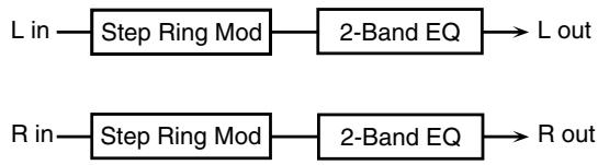
flowchart
graph LR
    A["L in"] --> B["Step Ring Mod"]
    B --> C["2-Band EQ"]
    C --> D["L out"]
    E["R in"] --> F["Step Ring Mod"]
    F --> G["2-Band EQ"]
    G --> H["R out"]
| Parameter | Range | Explanation |
| Step 01–16 | 0–127 | Frequency of ring modulation at each step |
| Rate # | 0.05–10.00 Hz, note | Rate at which the 16-step sequence will cycle |
| Attack # | 0–127 | Speed at which the modulation frequency changes between steps |
| Low Gain | -15– +15 dB | Amount of boost/cut for the low-frequency range |
| High Gain | -15– +15 dB | Amount of boost/cut for the high-frequency range |
| Balance # | D100:0W–D0:100W | Volume balance of the original sound (D) and effect sound (W) |
| Level | 0–127 | Output volume |
17: TREMOLO
Cyclically modulates the volume to add tremolo effect to the sound.
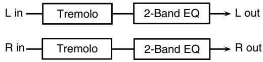
flowchart
graph LR
    A["L in"] --> B["Tremolo"]
    B --> C["2-Band EQ"] --> D["L out"]
    E["R in"] --> F["Tremolo"]
    F --> G["2-Band EQ"] --> H["R out"]
| Parameter | Value | Description |
| Mod Wave | TRI, SQR, SIN, SAW1, SAW2 | Modulation WaveTRI: triangle waveSQR: square waveSIN: sine waveSAW1/2: sawtooth wave |
SAW1 SAW2 | ||
| Rate # | 0.05–10.00 Hz, note | Frequency of the change |
| Depth # | 0–127 | Depth to which the effect is applied |
| Low Gain | -15– +15 dB | Gain of the low range |
| High Gain | -15– +15 dB | Gain of the high range |
| Level | 0–127 | Output Level |
18: AUTO PAN
Cyclically modulates the stereo location of the sound.
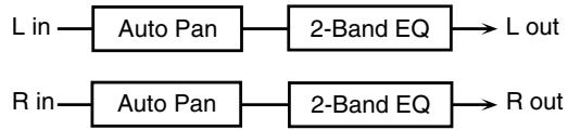
flowchart
graph LR
    A["L in"] --> B["Auto Pan"]
    B --> C["2-Band EQ"]
    C --> D["L out"]
    E["R in"] --> F["Auto Pan"]
    F --> G["2-Band EQ"]
    G --> H["R out"]
| Parameter | Value | Description |
| Mod Wave | TRI, SQR, SIN, SAW1, SAW2 | Modulation WaveTRI: triangle waveSQR: square waveSIN: sine waveSAW1/2: sawtooth wave |
SAW1 R  L L L L | ||
| Rate # | 0.05–10.00 Hz, note | Frequency of the change |
| Depth # | 0–127 | Depth to which the effect is applied |
| Low Gain | -15– +15 dB | Gain of the low range |
| High Gain | -15– +15 dB | Gain of the high range |
| Level | 0–127 | Output Level |
19: STEP PAN
This uses a 16-step sequence to vary the panning of the sound.
flowchart
graph LR
    A["L in"] --> B["Step Pan"] --> C["L out"]
    D["R in"] --> E["Step Pan"] --> F["R out"]
| Parameter | Range | Explanation |
| Step 01–16 | L64–63R | Pan at each step |
| Rate # | 0.05–10.00 Hz, note | Rate at which the 16-step sequence will cycle |
| Attack # | 0–127 | Speed at which the pan changes between steps |
| Input Sync Sw | OFF, ON | Specifies whether an input note will cause the sequence to resume from the first step of the sequence (ON) or not (OFF) |
| Input Sync Threshold | 0–127 | Volume at which an input note will be detected |
| Level | 0–127 | Output volume |
20: SLICER
By applying successive cuts to the sound, this effect turns a conventional sound into a sound that appears to be played as a backing phrase. This is especially effective when applied to sustain-type sounds.
flowchart
graph LR
    A["L in"] --> B["Slicer"]
    C["R in"] --> D["Slicer"]
    B --> E["L out"]
    D --> F["R out"]
| Parameter | Value | Description |
| Step 01-16 | 0-127 | Level at each step |
| Rate # | 0.05-10.00 Hz, note | Rate at which the 16-step sequence will cycle |
| Attack # | 0-127 | Speed at which the level changes between steps |
| Input Sync Sw | OFF, ON | Specifies whether an input note will cause the sequence to resume from the first step of the sequence (ON) or not (OFF) |
| Input Sync Threshold | 0-127 | Volume at which an input note will be detected |
| Mode | LEGATO, SLASH | Sets the manner in which the volume changes as one step progresses to the next.LEGATO: The change in volume from one step's level to the next remains unaltered. If the level of a following step is the same as the one preceding it, there is no change in volume.SLASH: The level is momentarily set to 0 before progressing to the level of the next step. This change in volume occurs even if the level of the following step is the same as the preceding step. |
| Shuffle # | 0-127 | Timing of volume changes in levels for even-numbered steps (step 2, step 4, step 6...).The higher the value, the later the beat progresses. |
| Level | 0-127 | Output level |
21: ROTARY
The Rotary effect simulates the sound of the rotary speakers often used with the electric organs of the past. Since the movement of the high range and low range rotors can be set independently, the unique type of modulation characteristic of these speakers can be simulated quite closely. This effect is most suitable for electric organ Patches.
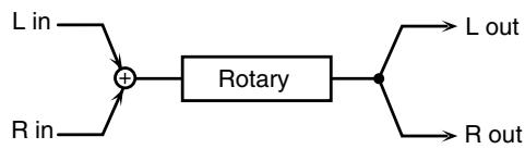
flowchart
graph LR
    A["L in"] --> C["+"]
    B["R in"] --> C["+"]
    C["+"] --> D["Rotary"]
    D["Rotary"] --> E["L out"]
    D["Rotary"] --> F["R out"]
| Parameter | Value | Description |
| Speed # | SLOW, FAST | Simultaneously switch the rotational speed of the low frequency rotor and high frequency rotor.SLOW: Slows down the rotation to the Slow Rate.FAST: Speeds up the rotation to the Fast Rate. |
| Woofer Slow Speed | 0.05–10.00 Hz | Slow speed (SLOW) of the low frequency rotor |
| Woofer Fast Speed | 0.05–10.00 Hz | Fast speed (FAST) of the low frequency rotor |
| Parameter | Value | Description |
| WooferAcceleration | 0–15 | Adjusts the time it takes the low frequency rotor to reach the newly selected speed when switching from fast to slow (or slow to fast) speed. Lower values will require longer times. |
| Woofer Level | 0–127 | Volume of the low frequency rotor |
| Tweeter Slow Speed | 0.05–10.00 Hz | Settings of the high frequency rotorThe parameters are the same as for the low frequency rotor |
| Tweeter Fast Speed | 0.05–10.00 Hz | |
| TweeterAcceleration | 0–15 | |
| Tweeter Level | 0–127 | |
| Separation | 0–127 | Spatial dispersion of the sound |
| Level # | 0–127 | Output Level |
22: VK ROTARY
This type provides modified response for the rotary speaker, with the low end boosted further.
This effect features the same specifications as the VK-7's built-in rotary speaker.

flowchart
graph LR
    A["L in"] --> C["+"]
    B["R in"] --> C
    C --> D["Rotary"]
    D --> E["2-Band EQ"] --> F["L out"]
    D --> G["2-Band EQ"] --> H["R out"]
| Parameter | Value | Description |
| Speed # | SLOW, FAST | Rotational speed of the rotating speaker |
| Brake # | OFF, ON | Switches the rotation of the rotary speaker.When this is turned on, the rotation will gradually stop. When it is turned off, the rotation will gradually resume. |
| Woofer Slow Speed | 0.05–10.00 Hz | Low-speed rotation speed of the woofer |
| Woofer Fast Speed | 0.05–10.00 Hz | High-speed rotation speed of the woofer |
| Woofer Trans Up | 0–127 | Adjusts the rate at which the woofer rotation speeds up when the rotation is switched from Slow to Fast. |
| Woofer Trans Down | 0–127 | Adjusts the rate at which the woofer rotation speeds up when the rotation is switched from Fast to Slow. |
| Woofer Level | 0–127 | Volume of the woofer |
| Tweeter Slow Speed | 0.05–10.00 Hz | Settings of the tweeterThe parameters are the same as for the woofer. |
| Tweeter Fast Speed | 0.05–10.00 Hz | |
| Tweeter Trans Up | 0–127 | |
| Tweeter Trans Down | 0–127 | |
| Tweeter Level | 0–127 | |
| Spread | 0–10 | Sets the rotary speaker stereo image. The higher the value set, the wider the sound is spread out. |
| Low Gain | -15– +15 dB | Gain of the low range |
| High Gain | -15– +15 dB | Gain of the high range |
| Level # | 0–127 | Output Level |
23: CHORUS
This is a stereo chorus. A filter is provided so that you can adjust the timbre of the chorus sound.
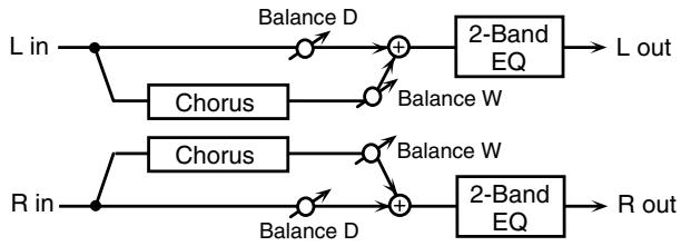
flowchart
graph LR
    A["L in"] --> B["Chorus"]
    B --> C["Balance D"]
    C --> D["+"]
    D --> E["2-Band EQ"]
    E --> F["L out"]
    G["R in"] --> H["Chorus"]
    H --> I["Balance D"]
    I --> J["+"]
    J --> K["2-Band EQ"]
    K --> L["R out"]
    D --> M["Balance W"]
    M --> N["+"]
    N --> O["2-Band EQ"]
    O --> P["Balance W"]
| Parameter | Value | Description |
| Filter Type | OFF, LPF, HPF | Type of filterOFF: no filter is usedLPF: cuts the frequency range above the Cutoff FreqHPF: cuts the frequency range below the Cutoff Freq |
| Cutoff Freq | 200–8000 Hz | Basic frequency of the filter |
| Pre Delay | 0.0–100.0 ms | Adjusts the delay time from the direct sound until the chorus sound is heard. |
| Rate # | 0.05–10.00 Hz, note | Frequency of modulation |
| Depth | 0–127 | Depth of modulation |
| Phase | 0–180 deg | Spatial spread of the sound |
| Low Gain | -15– +15 dB | Gain of the low range |
| High Gain | -15– +15 dB | Gain of the high range |
| Balance # | D100:0W–D0:100W | Volume balance between the direct sound (D) and the chorus sound (W) |
| Level | 0–127 | Output Level |
24: FLANGER
This is a stereo flanger. (The LFO has the same phase for left and right.) It produces a metallic resonance that rises and falls like a jet airplane taking off or landing. A filter is provided so that you can adjust the timbre of the flanged sound.
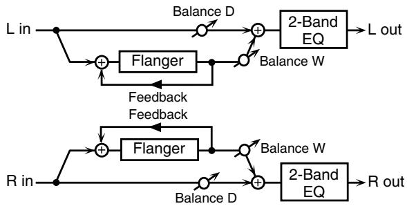
flowchart
graph TD
    A["L in"] --> B["+"]
    B --> C["Flanger"]
    C --> D["+"]
    D --> E["2-Band EQ"]
    E --> F["L out"]
    G["R in"] --> H["+"]
    H --> I["Flanger"]
    I --> J["+"]
    J --> K["2-Band EQ"]
    K --> L["R out"]
    B --> M["Feedback"]
    I --> N["Feedback"]
    M --> O["Balance D"]
    N --> P["Balance W"]
| Parameter | Value | Description |
| Filter Type | OFF, LPF, HPF | Type of filterOFF: no filter is usedLPF: cuts the frequency range above the Cutoff FreqHPF: cuts the frequency range below the Cutoff Freq |
| Cutoff Freq | 200–8000 Hz | Basic frequency of the filter |
| Pre Delay | 0.0–100.0 ms | Adjusts the delay time from when the direct sound begins until the flanger sound is heard. |
| Rate # | 0.05–10.00 Hz, note | Frequency of modulation |
| Depth | 0–127 | Depth of modulation |
| Phase | 0–180 deg | Spatial spread of the sound |
| Feedback # | -98– +98 % | Adjusts the proportion of the flanger sound that is fed back into the effect. Negative (-) settings will invert the phase. |
| Low Gain | -15– +15 dB | Gain of the low range |
| Parameter | Value | Description |
| High Gain | -15– +15 dB | Gain of the high range |
| Balance # | D100:0W–D0:100W | Volume balance between the direct sound (D) and the flanger sound (W) |
| Level | 0–127 | Output Level |
25: STEP FLANGER
This is a flanger in which the flanger pitch changes in steps. The speed at which the pitch changes can also be specified in terms of a note-value of a specified tempo.
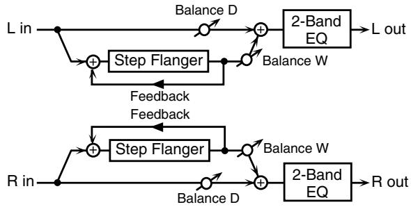
flowchart
graph TD
    L_in --> A["+"]
    A --> B["Step Flanger"]
    B --> C["+"]
    C --> D["2-Band EQ"]
    D --> L_out["L out"]
    R_in --> E["+"]
    E --> F["Step Flanger"]
    F --> G["+"]
    G --> H["2-Band EQ"]
    H --> R_out["R out"]
    A --> I["Balance D"]
    I --> J["+"]
    J --> K["Balance W"]
    K --> C
    E --> L["Balance D"]
    L --> M["+"]
    M --> N["Balance W"]
    N --> G
    A --> O["Feedback"]
    O --> P["+"]
    P --> Q["Balance W"]
    Q --> H
| Parameter | Value | Description |
| Filter Type | OFF, LPF, HPF | Type of filterOFF: no filter is usedLPF: cuts the frequency range above the Cutoff FreqHPF: cuts the frequency range below the Cutoff Freq |
| Cutoff Freq | 200–8000 Hz | Basic frequency of the filter |
| Pre Delay | 0.0–100.0 ms | Adjusts the delay time from when the direct sound begins until the flanger sound is heard. |
| Rate # | 0.05–10.00 Hz, note | Frequency of modulation |
| Depth | 0–127 | Depth of modulation |
| Phase | 0–180 deg | Spatial spread of the sound |
| Feedback # | -98– +98 % | Adjusts the proportion of the flanger sound that is fed back into the effect. Negative (-) settings will invert the phase. |
| Step Rate # | 0.10–20.00 Hz, note | Rate (period) of pitch change |
| Low Gain | -15– +15 dB | Gain of the low range |
| High Gain | -15– +15 dB | Gain of the high range |
| Balance # | D100:0W–D0:100W | Volume balance between the direct sound (D) and the flanger sound (W) |
| Level | 0–127 | Output Level |
26: HEXA-CHORUS
Uses a six-phase chorus (six layers of chorused sound) to give richness and spatial spread to the sound.
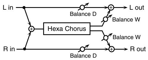
flowchart
graph TD
    L_in --> A["+"]
    R_in --> A
    A --> B["Hexa Chorus"]
    B --> C["+"]
    D["Balance D"] --> C
    E["Balance W"] --> C
    F["Balance W"] --> C
    G["Balance D"] --> H["+"]
    I["R out"] --> H
    H --> J["L out"]
| Parameter | Value | Description |
| Pre Delay | 0.0–100.0 ms | Adjusts the delay time from the direct sound until the chorus sound is heard. |
| Rate # | 0.05–10.00 Hz, note | Frequency of modulation |
| Depth | 0–127 | Depth of modulation |
| Pre Delay Deviation | 0–20 | Adjusts the differences in Pre Delay between each chorus sound. |
| Depth Deviation | -20–+20 | Adjusts the difference in modulation depth between each chorus sound. |
| Pan Deviation | 0–20 | Adjusts the difference in stereo location between each chorus sound.0: All chorus sounds will be in the center.20: Each chorus sound will be spaced at 60 degree intervals relative to the center. |
| Balance # | D100:0W–D0:100W | Volume balance between the direct sound (D) and the chorus sound (W) |
| Level | 0–127 | Output Level |
27: TREMOLO CHORUS
This is a chorus effect with added Tremolo (cyclic modulation of volume).
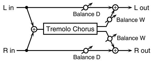
flowchart
graph TD
    L_in --> A["+"]
    R_in --> B["-"]
    A --> C["Tremolo Chorus"]
    B --> C
    C --> D1["Balance D"]
    C --> D2["Balance W"]
    C --> D3["Balance W"]
    C --> D4["Balance D"]
    D1 --> E1["L out"]
    D2 --> E2["R out"]
    D3 --> E3["Balance W"]
    D4 --> E4["Balance W"]
| Parameter | Value | Description |
| Pre Delay | 0.0–100.0 ms | Adjusts the delay time from the direct sound until the chorus sound is heard. |
| Chorus Rate # | 0.05–10.00 Hz, note | Modulation frequency of the chorus effect |
| Chorus Depth | 0–127 | Modulation depth of the chorus effect |
| Tremolo Rate # | 0.05–10.00 Hz, note | Modulation frequency of the tremolo effect |
| Tremolo Separation | 0–127 | Spread of the tremolo effect |
| Tremolo Phase | 0–180 deg | Spread of the tremolo effect |
| Balance # | D100:0W–D0:100W | Volume balance between the direct sound (D) and the tremolo chorus sound (W) |
| Level | 0–127 | Output Level |
28: SPACE-D
This is a multiple chorus that applies two-phase modulation in stereo. It gives no impression of modulation, but produces a transparent chorus effect.
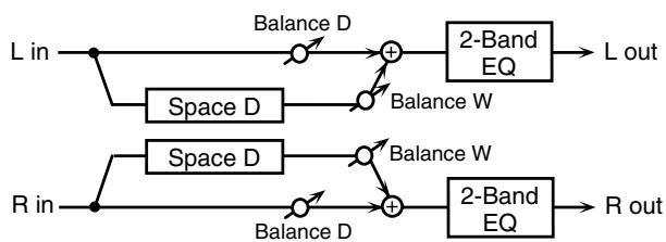
flowchart
graph LR
    L_in --> A1["Balance D"]
    A1 --> B1["+"]
    B1 --> C1["2-Band EQ"]
    C1 --> L_out["L out"]
    R_in --> A2["Balance D"]
    A2 --> B2["+"]
    B2 --> C2["2-Band EQ"]
    C2 --> R_out["R out"]
    A1 --> Space_D1["Space D"]
    Space_D1 --> B1
    B1 --> Space_D2["Space D"]
    Space_D2 --> B2
    B2 --> Space_D3["Space D"]
    Space_D3 --> B3["+"]
    B3 --> Space_D4["Balance W"]
    Space_D4 --> B4["Balance W"]
    Space_D4 --> B5["Balance W"]
| Parameter | Value | Description |
| Pre Delay | 0.0–100.0 ms | Adjusts the delay time from the direct sound until the chorus sound is heard. |
| Rate # | 0.05–10.00 Hz, note | Frequency of modulation |
| Depth | 0–127 | Depth of modulation |
| Phase | 0–180 deg | Spatial spread of the sound |
| Low Gain | -15– +15 dB | Gain of the low range |
| High Gain | -15– +15 dB | Gain of the high range |
| Balance # | D100:0W–D0:100W | Volume balance between the direct sound (D) and the chorus sound (W) |
| Level | 0–127 | Output Level |
29: 3D CHORUS
This applies a 3D effect to the chorus sound. The chorus sound will be positioned 90 degrees left and 90 degrees right.
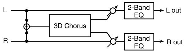
flowchart
graph LR
    L --> A["3D Chorus"]
    R --> A
    A --> B["2-Band EQ"]
    B --> C["L out"]
    A --> D["2-Band EQ"]
    D --> E["R out"]
| Parameter | Value | Description |
| Filter Type | OFF, LPF, HPF | Type of filterOFF: no filter is usedLPF: cuts the frequency range above the Cutoff FreqHPF: cuts the frequency range below the Cutoff Freq |
| Cutoff Freq | 200–8000 Hz | Basic frequency of the filter |
| Pre Delay | 0.0–100.0 ms | Adjusts the delay time from the direct sound until the chorus sound is heard. |
| Rate # | 0.05–10.00 Hz, note | Frequency of modulation |
| Depth | 0–127 | Modulation depth of the chorus effect |
| Phase | 0–180 deg | Spatial spread of the sound |
| Output Mode | SPEAKER, PHONES | Adjusts the method that will be used to hear the sound that is output to the OUTPUT jacks. The optimal 3D effect will be achieved if you select SPEAK-ER when using speakers, or PHONES when using headphones. |
| Low Gain | -15– +15 dB | Gain of the low range |
| High Gain | -15– +15 dB | Gain of the high range |
| Balance # | D100:0W–D0:100W | Volume balance between the direct sound (D) and the chorus sound (W) |
| Level | 0–127 | Output Level |
30: 3D FLANGER
This applies a 3D effect to the flanger sound. The flanger sound will be positioned 90 degrees left and 90 degrees right.
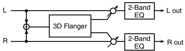
flowchart
graph LR
    L --> A["+"]
    R --> B["3D Flanger"]
    A --> C["○"]
    B --> D["○"]
    C --> E["2-Band EQ"] --> F["L out"]
    D --> G["2-Band EQ"] --> H["R out"]
| Parameter | Value | Description |
| Filter Type | OFF, LPF, HPF | Type of filterOFF: no filter is usedLPF: cuts the frequency range above the Cutoff FreqHPF: cuts the frequency range below the Cutoff Freq |
| Cutoff Freq | 200–8000 Hz | Basic frequency of the filter |
| Pre Delay | 0.0–100.0 ms | Adjusts the delay time from when the direct sound begins until the flanger sound is heard. |
| Rate # | 0.05–10.00 Hz, note | Frequency of modulation |
| Depth | 0–127 | Depth of modulation |
| Phase | 0–180 deg | Spatial spread of the sound |
| Feedback # | -98– +98 % | Adjusts the proportion of the flanger sound that is fed back into the effect. Negative (-) settings will invert the phase. |
| Output Mode | SPEAKER, PHONES | Adjusts the method that will be used to hear the sound that is output to the OUTPUT jacks. The optimal 3D effect will be achieved if you select SPEAKER when using speakers, or PHONES when using headphones. |
| Low Gain | -15– +15 dB | Gain of the low range |
| High Gain | -15– +15 dB | Gain of the high range |
| Balance # | D100:0W–D0:100W | Volume balance between the direct sound (D) and the flanger sound (W) |
| Level | 0–127 | Output Level |
31: 3D STEP FLANGER
This applies a 3D effect to the step flanger sound. The flanger sound will be positioned 90 degrees left and 90 degrees right.
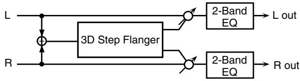
flowchart
graph LR
    L --> A["3D Step Flanger"]
    R --> A
    A --> B["2-Band EQ"]
    B --> C["L out"]
    A --> D["2-Band EQ"]
    D --> E["R out"]
| Parameter | Value | Description |
| Filter Type | OFF, LPF, HPF | Type of filterOFF: no filter is usedLPF: cuts the frequency range above the Cutoff FreqHPF: cuts the frequency range below the Cutoff Freq |
| Cutoff Freq | 200–8000 Hz | Basic frequency of the filter |
| Pre Delay | 0.0–100.0 ms | Adjusts the delay time from when the direct sound begins until the flanger sound is heard. |
| Rate # | 0.05–10.00 Hz, note | Frequency of modulation |
| Depth | 0–127 | Depth of modulation |
| Phase | 0–180 deg | Spatial spread of the sound |
| Parameter | Value | Description |
| Feedback # | -98– +98 % | Adjusts the proportion of the flanger sound that is fed back into the effect. Negative (-) settings will invert the phase. |
| Step Rate # | 0.10–20.00 Hz, note | Rate (period) of pitch change |
| Output Mode | SPEAKER, PHONES | Adjusts the method that will be used to hear the sound that is output to the OUTPUT jacks. The optimal 3D effect will be achieved if you select SPEAK-ER when using speakers, or PHONES when using headphones. |
| Low Gain | -15– +15 dB | Gain of the low range |
| High Gain | -15– +15 dB | Gain of the high range |
| Balance # | D100:0W–D0:100W | Volume balance between the direct sound (D) and the flanger sound (W) |
| Level | 0–127 | Output Level |
32: 2BAND CHORUS
A chorus effect that lets you apply an effect independently to the low-frequency and high-frequency ranges.
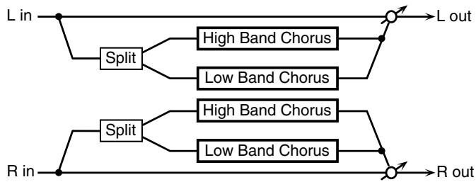
flowchart
graph TD
    A["L in"] --> B["Split"]
    B --> C["High Band Chorus"]
    B --> D["Low Band Chorus"]
    E["R in"] --> F["Split"]
    F --> G["High Band Chorus"]
    F --> H["Low Band Chorus"]
    I["L out"] --> J["Output"]
    K["R out"] --> L["Output"]
| Parameter | Range | Explanation |
| Split Freq | 200–8000 Hz | Frequency at which the low and high ranges will be divided |
| Low Pre Delay | 0.0–100.0 ms | Delay time from when the original sound is heard to when the low-range chorus sound is heard |
| Low Rate # | 0.05–10.00 Hz, note | Rate at which the low-range chorus sound is modulated |
| Low Depth | 0–127 | Modulation depth for the low-range chorus sound |
| Low Phase | 0–180 deg | Spaciousness of the low-range chorus sound |
| High Pre Delay | 0.0–100.0 ms | Delay time from when the original sound is heard to when the high-range chorus sound is heard |
| High Rate # | 0.05–10.00 Hz, note | Rate at which the low-range chorus sound is modulated |
| High Depth | 0–127 | Modulation depth for the high-range chorus sound |
| High Phase | 0–180 deg | Spaciousness of the high-range chorus sound |
| Balance # | D100:0W–D0:100W | Volume balance of the original sound (D) and chorus sound (W) |
| Level | 0–127 | Output volume |
33: 2BAND FLANGER
A flanger that lets you apply an effect independently to the low-frequency and high-frequency ranges.
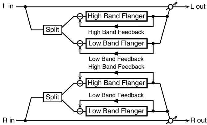
flowchart
graph TD
    A["L in"] --> B["Split"]
    B --> C1["+"]
    B --> C2["Low Band Flanger"]
    C1 --> D1["High Band Flanger"]
    C2 --> D2["Low Band Flanger"]
    D1 --> E1["L out"]
    D2 --> E2["R out"]
    F["R in"] --> G["Split"]
    G --> H1["+"]
    G --> H2["Low Band Flanger"]
    H1 --> I1["High Band Flanger"]
    H2 --> I2["Low Band Flanger"]
    I1 --> J1["L out"]
    I2 --> J2["R out"]
    K["High Band Feedback"] --> C1
    K --> D1
    L["Low Band Feedback"] --> C2
    L --> D2
| Parameter | Range | Explanation |
| Split Freq | 200–8000 Hz | Frequency at which the low and high ranges will be divided |
| Low Pre Delay | 0.0–100.0 ms | Delay time from when the original sound is heard to when the low-range flanger sound is heard |
| Low Rate # | 0.05–10.00 Hz, note | Rate at which the low-range flanger sound is modulated |
| Low Depth | 0–127 | Modulation depth for the low-range flanger sound |
| Low Phase | 0–180 deg | Spaciousness of the low-range flanger sound |
| Low Feedback # | -98– +98% | Proportion of the low-range flanger sound that is to be returned to the input (negative values invert the phase) |
| High Pre Delay | 0.0–100.0 ms | Delay time from when the original sound is heard to when the high-range flanger sound is heard |
| High Rate # | 0.05–10.00 Hz, note | Rate at which the high-range flanger sound is modulated |
| High Depth | 0–127 | Modulation depth for the high-range flanger sound |
| High Phase | 0–180 deg | Spaciousness of the high-range flanger sound |
| High Feedback # | -98– +98% | Proportion of the high-range flanger sound that is to be returned to the input (negative values invert the phase) |
| Balance # | D100:0W–D0:100W | Volume balance of the original sound (D) and flanger sound (W) |
| Level | 0–127 | Output volume |
34: 2BAND STEP FLANGER
A step flanger that lets you apply an effect independently to the low-frequency and high-frequency ranges.
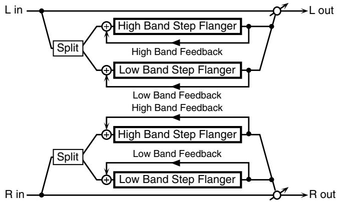
flowchart
graph TD
    A["L in"] --> B["Split"]
    B --> C1["High Band Step Flanger"]
    B --> C2["Low Band Step Flanger"]
    C1 --> D1["L out"]
    C2 --> D2["R out"]
    E["R in"] --> F["Split"]
    F --> G1["High Band Step Flanger"]
    F --> G2["Low Band Step Flanger"]
    G1 --> H1["L out"]
    G2 --> H2["R out"]
    I["High Band Feedback"] --> B
    J["Low Band Feedback"] --> C1
    K["High Band Feedback"] --> D1
    L["Low Band Feedback"] --> E
| Parameter | Range | Explanation |
| Split Freq | 200–8000 Hz | Frequency at which the low and high ranges will be divided |
| Low Pre Delay | 0.0–100.0 ms | Delay time from when the original sound is heard to when the low-range flanger sound is heard |
| Low Rate # | 0.05–10.00 Hz, note | Rate at which the low-range flanger sound is modulated |
| Low Depth | 0–127 | Modulation depth for the low-range flanger sound |
| Low Phase | 0–180 deg | Spaciousness of the low-range flanger sound |
| Low Feedback # | -98– +98% | Proportion of the low-range flanger sound that is to be returned to the input (negative values invert the phase) |
| Low Step Rate # | 0.10–20.00 Hz, note | Rate at which the steps will cycle for the low-range flanger sound |
| High Pre Delay | 0.0–100.0 ms | Delay time from when the original sound is heard to when the high-range flanger sound is heard |
| High Rate # | 0.05–10.00 Hz, note | Rate at which the high-range flanger sound is modulated |
| High Depth | 0–127 | Modulation depth for the high-range flanger sound |
| High Phase | 0–180 deg | Spaciousness of the high-range flanger sound |
| High Feedback # | -98– +98% | Proportion of the high-range flanger sound that is to be returned to the input (negative values invert the phase) |
| High Step Rate # | 0.10–20.00 Hz, note | Rate at which the steps will cycle for the high-range flanger sound |
| Balance # | D100:0W–D0:100W | Volume balance of the original sound (D) and flanger sound (W) |
| Level | 0–127 | Output volume |
35: OVERDRIVE
Creates a soft distortion similar to that produced by vacuum tube amplifiers.
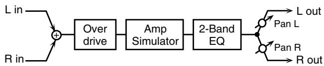
flowchart
graph LR
    A["L in"] --> C["+"]
    B["R in"] --> C
    C --> D["Over drive"]
    D --> E["Amp Simulator"]
    E --> F["2-Band EQ"]
    F --> G["L out"]
    F --> H["Pan L"]
    F --> I["Pan R"]
    F --> J["R out"]
| Parameter | Value | Description |
| Drive # | 0–127 | Degree of distortionAlso changes the volume. |
| Amp Type | SMALL,BUILT-IN,2-STACK,3-STACK | Type of guitar ampSMALL:small ampBUILT-IN:single-unit type amp2-STACK:large double stack amp3-STACK:large triple stack amp |
| Low Gain | -15– +15 dB | Gain of the low range |
| High Gain | -15– +15 dB | Gain of the high range |
| Pan # | L64–63R | Stereo location of the output sound |
| Level | 0–127 | Output Level |
36: DISTORTION
Produces a more intense distortion than Overdrive. The parameters are the same as for “35: OVERDRIVE.”
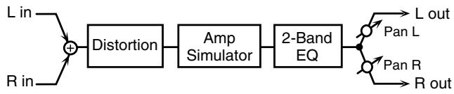
flowchart
graph LR
    A["L in"] --> C["+"]
    B["R in"] --> C["+"]
    C["+"] --> D["Distortion"]
    D --> E["Amp Simulator"]
    E --> F["2-Band EQ"]
    F --> G["Pan L"]
    F --> H["Pan R"]
    F --> I["R out"]
37: VS OVERDRIVE
This is an overdrive that provides heavy distortion.
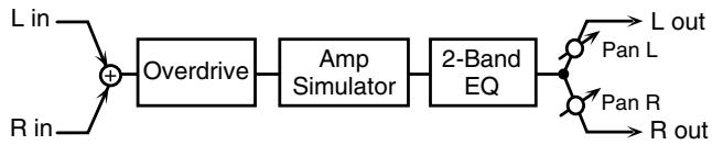
flowchart
graph LR
    A["L in"] --> C["+"]
    B["R in"] --> C
    C --> D["Overdrive"]
    D --> E["Amp Simulator"]
    E --> F["2-Band EQ"]
    F --> G["Pan L"]
    F --> H["Pan R"]
    F --> I["R out"]
| Parameter | Value | Description |
| Drive # | 0-127 | Degree of distortionAlso changes the volume. |
| Tone # | 0-127 | Sound quality of the Overdrive effect |
| Amp Sw | OFF, ON | Turns the Amp Simulator on/off. |
| Amp Type | SMALL,BUILT-IN,2-STACK,3-STACK | Type of guitar ampSMALL:small ampBUILT-IN:single-unit type amp2-STACK:large double stack amp3-STACK:large triple stack amp |
| Low Gain | -15- +15 dB | Gain of the low range |
| High Gain | -15- +15 dB | Gain of the high range |
| Pan # | L64-63R | Stereo location of the output sound |
| Level | 0-127 | Output Level |
38: VS DISTORTION
This is a distortion effect that provides heavy distortion. The parameters are the same as for “37: VS OVERDRIVE.”
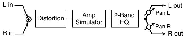
flowchart
graph LR
    A["L in"] --> C["+"]
    B["R in"] --> C["+"]
    C["+"] --> D["Distortion"]
    D --> E["Amp Simulator"]
    E --> F["2-Band EQ"]
    F --> G["Pan L"]
    F --> H["Pan R"]
    F --> I["R out"]
39: GUITAR AMP SIMULATOR
This is an effect that simulates the sound of a guitar amplifier.
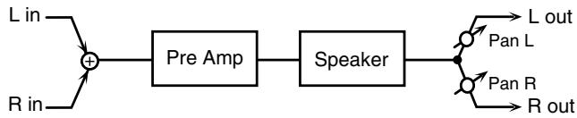
flowchart
graph LR
    A["L in"] --> C["+"]
    B["R in"] --> C["+"]
    C["+"] --> D["Pre Amp"]
    D["Pre Amp"] --> E["Speaker"]
    E["Speaker"] --> F["L out"]
    E["Speaker"] --> G["R out"]
    H["L out"] --> I["Pan L"]
    J["R out"] --> K["Pan R"]
| Parameter | Value | Description |
| Pre Amp Sw | OFF, ON | Turns the amp switch on/off. |
| Pre Amp Type | JC-120, CLEAN TWIN, MATCH DRIVE, BG LEAD, MS1959I, MS1959II, MS1959I+II, SLDN LEAD, METAL5150, METAL LEAD, OD-1, OD-2 TURBO, DISTORTION, FUZZ | Type of guitar amp |
| Pre Amp Volume # | 0–127 | Volume and amount of distortion of the amp |
| Pre Amp Master # | 0–127 | Volume of the entire pre-amp |
| Pre Amp Gain | LOW, MIDDLE, HIGH | Amount of pre-amp distortion |
| Pre Amp Bass | 0–127 | Tone of the bass/mid/treble frequency range* Middle cannot be set if “Match Drive” is selected as the Pre Amp Type. |
| Pre Amp Middle | ||
| Pre Amp Treble | ||
| Pre Amp Presence | 0–127 (MATCH DRIVE: -127 - 0) | Tone for the ultra-high frequency range |
| Pre Amp Bright | OFF, ON | Turning this “On” produces a sharper and brighter sound.* This parameter applies to the “JC-120,” “Clean Twin,” and “BG Lead” Pre Amp Types. |
| Speaker Sw | OFF, ON | Determines whether the signal passes through the speaker (ON), or not (OFF). |
| Speaker Type | (See the table below.) | Type of speaker |
| Mic Setting | 1, 2, 3 | Adjusts the location of the mic that’s capturing the sound of the speaker.This can be adjusted in three steps, from 1 to 3, with the mic becoming more distant as the value increases. |
| Mic Level | 0–127 | Volume of the microphone |
| Direct Level | 0–127 | Volume of the direct sound |
| Pan # | L64–63R | Stereo location of the output |
| Level # | 0–127 | Output level |
Specifications for each Speaker Type
The speaker column indicates the diameter of each speaker unit (in inches) and the number of units.
| Type | Cabinet | Speaker | Microphone |
| SMALL 1 | small open-back enclosure | 10 | dynamic |
| SMALL 2 | small open-back enclosure | 10 | dynamic |
| MIDDLE | open back enclosure | 12 x 1 | dynamic |
| JC-120 | open back enclosure | 12 x 2 | dynamic |
| BUILT-IN 1 | open back enclosure | 12 x 2 | dynamic |
| BUILT-IN 2 | open back enclosure | 12 x 2 | condenser |
| BUILT-IN 3 | open back enclosure | 12 x 2 | condenser |
| BUILT-IN 4 | open back enclosure | 12 x 2 | condenser |
| BUILT-IN 5 | open back enclosure | 12 x 2 | condenser |
| BG STACK 1 | sealed enclosure | 12 x 2 | condenser |
| BG STACK 2 | large sealed enclosure | 12 x 2 | condenser |
| MS STACK 1 | large sealed enclosure | 12 x 4 | condenser |
| MS STACK 2 | large sealed enclosure | 12 x 4 | condenser |
| METAL STACK | large double stack | 12 x 4 | condenser |
| 2-STACK | large double stack | 12 x 4 | condenser |
| 3-STACK | large triple stack | 12 x 4 | condenser |
40: COMPRESSOR
Flattens out high levels and boosts low levels, smoothing out fluctuations in volume.
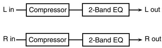
flowchart
graph LR
    A["L in"] --> B["Compressor"]
    B --> C["2-Band EQ"]
    C --> D["L out"]
    E["R in"] --> F["Compressor"]
    F --> G["2-Band EQ"]
    G --> H["R out"]
| Parameter | Value | Description |
| Attack # | 0–127 | Sets the speed at which compression starts |
| Threshold # | 0–127 | Adjusts the volume at which compression begins |
| Post Gain | 0– +18 dB | Adjusts the output gain. |
| Low Gain | -15– +15 dB | Gain of the low frequency range |
| High Gain | -15– +15 dB | Gain of the high frequency range |
| Level # | 0–127 | Output level |
41: LIMITER
Compresses signals that exceed a specified volume level, preventing distortion from occurring.
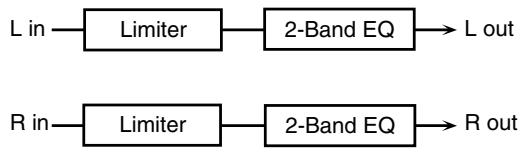
flowchart
graph LR
    A["L in"] --> B["Limiter"]
    B --> C["2-Band EQ"] --> D["L out"]
    E["R in"] --> F["Limiter"]
    F --> G["2-Band EQ"] --> H["R out"]
| Parameter | Value | Description |
| Release # | 0-127 | Adjusts the time after the signal volume falls below the Threshold Level until compression is no longer applied. |
| Threshold # | 0-127 | Adjusts the volume at which compression begins |
| Ratio | 1.5:1, 2:1, 4:1, 100:1 | Compression ratio |
| Post Gain | 0- +18 dB | Adjusts the output gain. |
| Low Gain | -15- +15 dB | Gain of the low frequency range |
| High Gain | -15- +15 dB | Gain of the high frequency range |
| Level # | 0-127 | Output level |
42: GATE
Cuts the reverb's delay according to the volume of the sound sent into the effect. Use this when you want to create an artificial-sounding decrease in the reverb's decay.
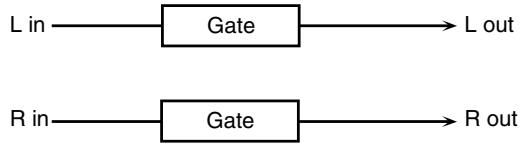
flowchart
graph LR
    A["L in"] --> B["Gate"]
    C["R in"] --> D["Gate"]
    B --> E["L out"]
    D --> F["R out"]
| Parameter | Value | Description |
| Threshold # | 0–127 | Volume level at which the gate begins to close |
| Mode | GATE, DUCK | Type of gateGATE: The gate will close when the volume of the original sound decreases, cutting the original sound.DUCK (Ducking): The gate will close when the volume of the original sound increases, cutting the original sound. |
| Attack | 0–127 | Adjusts the time it takes for the gate to fully open after being triggered. |
| Parameter | Value | Description |
| Hold | 0–127 | Adjusts the time it takes for the gate to start closing after the source sound falls beneath the Threshold. |
| Release | 0–127 | Adjusts the time it takes the gate to fully close after the hold time. |
| Balance # | D100:0W–D0:100W | Volume balance between the direct sound (D) and the effect sound (W) |
| Level | 0–127 | Output level |
43: DELAY
This is a stereo delay.
When Feedback Mode is NORMAL:
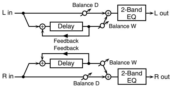
flowchart
graph TD
    A["L in"] --> B["+"]
    B --> C["Delay"]
    C --> D["+"]
    D --> E["2-Band EQ"]
    E --> F["L out"]
    G["R in"] --> H["+"]
    H --> I["Delay"]
    I --> J["+"]
    J --> K["2-Band EQ"]
    K --> L["R out"]
    M["Balance D"] --> D
    N["Balance W"] --> J
    O["Feedback Feedback"] --> B
    P["Balance D"] --> H
    Q["Balance W"] --> J
When Feedback Mode is CROSS:
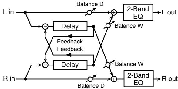
flowchart
graph TD
    A["L in"] --> B["+"]
    C["R in"] --> D["+"]
    B --> E["Delay"]
    D --> F["Delay"]
    E --> G["Balance D"]
    F --> H["Balance D"]
    G --> I["+"]
    H --> J["+"]
    I --> K["2-Band EQ"]
    J --> L["2-Band EQ"]
    K --> M["L out"]
    L --> N["R out"]
    O["Feedback Feedback"] --> B
    O --> D
    P["Balance W"] --> I
    Q["Balance W"] --> J
| Parameter | Value | Description |
| Delay Left | 0-1300 ms, note | Adjusts the time until the delay sound is heard. |
| Delay Right | ||
| Phase Left | NORMAL, INVERSE | Phase of the delay sound |
| Phase Right | ||
| Feedback Mode | NORMAL, CROSS | Selects the way in which delay sound is fed back into the effect. (See the figures above.) |
| Feedback # | -98- +98 % | Adjusts the amount of the delay sound that's fed back into the effect. Negative (-) settings invert the phase. |
| HF Damp | 200-8000 Hz, BYPASS | Adjusts the frequency above which sound fed back to the effect is filtered out. If you don't want to filter out any high frequencies, set this parameter to BYPASS. |
| Low Gain | -15- +15 dB | Gain of the low frequency range |
| High Gain | -15- +15 dB | Gain of the high frequency range |
| Balance # | D100:0W-D0:100W | Volume balance between the direct sound (D) and the delay sound (W) |
| Level | 0-127 | Output level |
44: LONG DELAY
A delay that provides a long delay time.
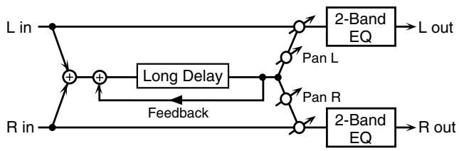
flowchart
graph TD
    A["L in"] --> B["+"]
    C["R in"] --> D["+"]
    B --> E["Long Delay"]
    D --> F["Feedback"]
    E --> G["Pan L"]
    F --> H["Pan R"]
    G --> I["2-Band EQ"]
    H --> J["2-Band EQ"]
    I --> K["L out"]
    J --> L["R out"]
| Parameter | Range | Explanation |
| Delay Time | 0–2600 ms, note | Delay time from when the original sound is heard to when the delay sound is heard |
| Phase | NORMAL, INVERSE | Phase of the delay (NORMAL: non-inverted, INVERT: inverted) |
| Feedback # | -98– +98% | Proportion of the delay sound that is to be returned to the input (negative values invert the phase) |
| HF Damp | 200–8000 Hz, BYPASS | Frequency at which the high-frequency content of the delayed sound will be cut (BY-PASS: no cut) |
| Pan # | L64–63R | Panning of the delay sound |
| Low Gain | -15– +15 dB | Amount of boost/cut for the high-frequency range |
| High Gain | -15– +15 dB | Amount of boost/cut for the high-frequency range |
| Balance # | D100:0W–D0:100W | Volume balance of the original sound (D) and delay sound (W) |
| Level | 0–127 | Output volume |
45: SERIAL DELAY
This delay connects two delay units in series. Feedback can be applied independently to each delay unit, allowing you to produce complex delay sounds.
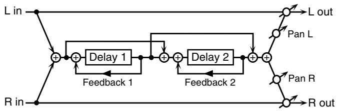
flowchart
graph TD
    A["L in"] --> B["+"]
    C["R in"] --> B
    B --> D["Delay 1"]
    D --> E["+"]
    F["Feedback 1"] --> E
    E --> G["+"]
    H["Feedback 2"] --> I["+"]
    J["Feedback 2"] --> I
    I --> K["+"]
    L["L out"] --> M["Pan L"]
    N["R out"] --> O["Pan R"]
    M --> L
    O --> P["Pan R"]
| Parameter | Range | Explanation |
| Delay1 Time | 0–1300 ms, note | Delay time from when sound is input to delay 1 until the delay sound is heard |
| Delay1 Feedback # | -98– +98% | Proportion of the delay sound that is to be returned to the input of delay 1 (negative values invert the phase) |
| Delay1 HF Damp | 200–8000 Hz, BYPASS | Frequency at which the high-frequency content of the delayed sound of delay 1 will be cut (BYPASS: no cut) |
| Delay2 Time | 0–1300 ms, note | Delay time from when sound is input to delay 2 until the delay sound is heard |
| Delay2 Feedback # | -98– +98% | Proportion of the delay sound that is to be returned to the input of delay 2 (negative values invert the phase) |
| Parameter | Range | Explanation |
| Delay2 HF Damp | 200–8000 Hz, BYPASS | Frequency at which the high-frequency content of the delayed sound of delay 2 will be cut (BYPASS: no cut) |
| Pan # | L64–63R | Panning of the delay sound |
| Low Gain | -15– +15 dB | Amount of boost/cut for the low-frequency range |
| High Gain | -15– +15 dB | Amount of boost/cut for the high-frequency range |
| Balance # | D100:0W–D0:100W | Volume balance of the original sound (D) and delay sound (W) |
| Level | 0–127 | Output volume |
46: MODULATION DELAY
Adds modulation to the delayed sound.
When Feedback Mode is NORMAL:
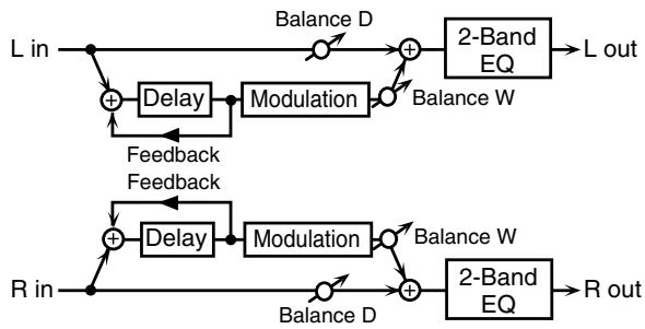
flowchart
graph TD
    A["L in"] --> B["+"]
    B --> C["Delay"]
    C --> D["Modulation"]
    D --> E["+"]
    E --> F["2-Band EQ"]
    F --> G["L out"]
    H["R in"] --> I["+"]
    I --> J["Delay"]
    J --> K["Modulation"]
    K --> L["+"]
    L --> M["2-Band EQ"]
    M --> N["R out"]
    B --> O["Feedback Feedback"]
    I --> P["Feedback Feedback"]
    O --> D
    P --> J
    style A fill:#f9f,stroke:#333
    style H fill:#f9f,stroke:#333
    style M fill:#f9f,stroke:#333
When Feedback Mode is CROSS:
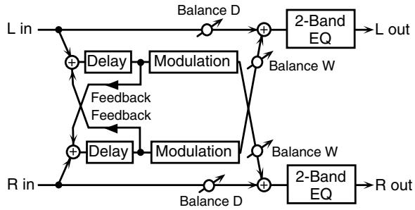
flowchart
graph TD
    L_in --> A["+"]
    R_in --> B["+"]
    A --> C["Delay"]
    B --> D["Delay"]
    C --> E["Modulation"]
    D --> F["Modulation"]
    E --> G["Balance D"]
    F --> H["Balance W"]
    G --> I["2-Band EQ"]
    H --> J["2-Band EQ"]
    I --> K["L out"]
    J --> L["R out"]
    M["Feedback Feedback"] --> A
    M --> B
    N["Balance D"] --> O["+"]
    P["Balance W"] --> Q["+"]
    R_out --> S["2-Band EQ"]
| Parameter | Value | Description |
| Delay Left | 0-1300 ms, note | Adjusts the time until the delay sound is heard. |
| Delay Right | ||
| Feedback Mode | NORMAL, CROSS | Selects the way in which delay sound is fed back into the effect (See the figures above.) |
| Feedback # | -98- +98 % | Adjusts the amount of the delay sound that's fed back into the effect. Negative (-) settings invert the phase. |
| HF Damp | 200-8000 Hz, BYPASS | Adjusts the frequency above which sound fed back to the effect is filtered out. If you don't want to filter out any high frequencies, set this parameter to BYPASS. |
| Rate # | 0.05-10.00 Hz, note | Frequency of modulation |
| Depth | 0-127 | Depth of modulation |
| Phase | 0-180 deg | Spatial spread of the sound |
| Low Gain | -15- +15 dB | Gain of the low frequency range |
| High Gain | -15- +15 dB | Gain of the high frequency range |
| Balance # | D100:0W-D0:100W | Volume balance between the direct sound (D) and the delay sound (W) |
| Level | 0-127 | Output level |
47: 3TAP PAN DELAY
Produces three delay sounds; center, left and right.
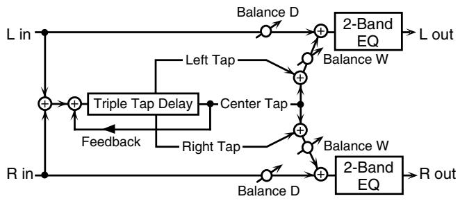
flowchart
graph TD
    L_in --> +1["+"]
    R_in --> +1
    +1 --> +2["+"]
    +2 --> +3["+"]
    +3 --> L_out["L out"]
    +2 --> +4["+"]
    +4 --> +5["+"]
    +5 --> L_out
    +3 --> +6["+"]
    +6 --> +7["+"]
    +7 --> L_out
    +6 --> +8["+"]
    +8 --> +9["+"]
    +9 --> L_out
    +8 --> +10["+"]
    +10 --> +11["+"]
    +11 --> L_out
    +9 --> +12["+"]
    +12 --> +13["+"]
    +13 --> L_out
    +10 --> +14["+"]
    +14 --> +15["+"]
    +15 --> L_out
    +12 --> +16["+"]
    +16 --> +17["+"]
    +17 --> L_out
    +10 --> +18["+"]
    +18 --> +19["+"]
    +19 --> L_out
    +8 --> +20["+"]
    +20 --> +21["+"]
    +21 --> L_out
    +6 --> +22["+"]
    +22 --> +23["+"]
    +23 --> L_out
    +4 --> +24["+"]
    +24 --> +25["+"]
    +25 --> L_out
    +20 --> +26["+"]
    +26 --> +27["+"]
    +27 --> L_out
    +16 --> +28["+"]
    +28 --> +29["+"]
    +29 --> L_out
    +14 --> +30["+"]
    +29 --> +31["+"]
    +31 --> L_out
    +12 --> +32["+"]
    +32 --> +33["+"]
    +33 --> L_out
    +8 --> +34["+"]
    +34 --> +35["+"]
    +35 --> L_out
| Parameter | Value | Description |
| Delay Left/Right/Center | 0–2600 ms, note | Adjusts the time until the delay sound is heard. |
| Center Feedback # | -98– +98 % | Adjusts the amount of the delay sound that's fed back into the effect. Negative (-) settings invert the phase. |
| HF Damp | 200–8000 Hz, BYPASS | Adjusts the frequency above which sound fed back to the effect is filtered out. If you do not want to filter out any high frequencies, set this parameter to BYPASS. |
| Left/Right/Center Level | 0–127 | Volume of each delay |
| Low Gain | -15– +15 dB | Gain of the low frequency range |
| High Gain | -15– +15 dB | Gain of the high frequency range |
| Balance # | D100:0W–D0:100W | Volume balance between the direct sound (D) and the delay sound (W) |
| Level | 0–127 | Output level |
48: 4TAP PAN DELAY
This effect has four delays.
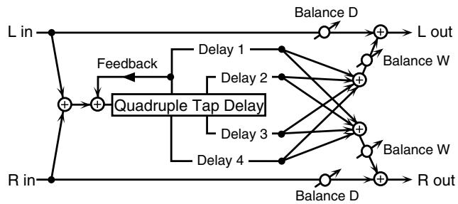
flowchart
graph TD
    L_in --> +1["+"]
    R_in --> +1
    +1 --> Feedback
    Feedback --> Quadruple_Tap_Delay
    Quadruple_Tap_Delay --> Delay1["Delay 1"]
    Quadruple_Tap_Delay --> Delay2["Delay 2"]
    Quadruple_Tap_Delay --> Delay3["Delay 3"]
    Quadruple_Tap_Delay --> Delay4["Delay 4"]
    Quadruple_Tap_Delay --> Balance_D["Balance D"]
    Quadruple_Tap_Delay --> Balance_W["Balance W"]
    Quadruple_Tap_Delay --> Balance_W
    Quadruple_Tap_Delay --> R_out["R out"]
    L_in --> +2["+"]
    R_in --> +2
    +2 --> Feedback
    Feedback --> Quadruple_Tap_Delay
    Quadruple_Tap_Delay --> Delay1
    Quadruple_Tap_Delay --> Delay2
    Quadruple_Tap_Delay --> Delay3
    Quadruple_Tap_Delay --> Delay4
    Balance_D --> +3["+"]
    Balance_W --> +3
    Balance_D --> +4["+"]
    Balance_W --> +4
    Balance_D --> R_out
    R_in --> +5["+"]
    L_out --> +6["+"]
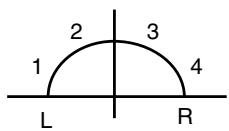
Stereo location of each delay
| Parameter | Value | Description |
| Delay 1–4 Time | 0–2600 ms, note | Adjusts the time until the delay sound is heard. |
| Delay 1 Feedback # | -98– +98 % | Adjusts the amount of the delay sound that's fed back into the effect. Negative (-) settings invert the phase. |
| HF Damp | 200–8000 Hz, BYPASS | Adjusts the frequency above which sound fed back to the effect is filtered out. If you do not want to filter out any high frequencies, set this parameter to BYPASS. |
| Delay 1–4 Level | 0–127 | Volume of each delay |
| Low Gain | -15– +15 dB | Gain of the low frequency range |
| High Gain | -15– +15 dB | Gain of the high frequency range |
| Balance # | D100:0W–D0:100W | Volume balance between the direct sound (D) and the delay sound (W) |
| Level | 0–127 | Output level |
49: MULTI TAP DELAY
This effect provides four delays. Each of the Delay Time parameters can be set to a note length based on the selected tempo. You can also set the panning and level of each delay sound.
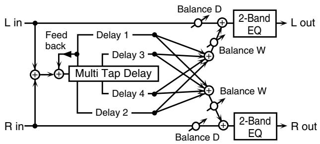
flowchart
graph TD
    L_in -->|Feedback| Multi_Tap_Delay["Multi Tap Delay"]
    R_in -->|Feedback| Multi_Tap_Delay
    Multi_Tap_Delay -->|Delay 1| Balance_D["Balance D"]
    Multi_Tap_Delay -->|Delay 2| Balance_D
    Multi_Tap_Delay -->|Delay 3| Balance_D
    Multi_Tap_Delay -->|Delay 4| Balance_D
    Multi_Tap_Delay -->|Balance W| 2_BandEQ["2-Band EQ"]
    2_BandEQ --> L_out["L out"]
    2_BandEQ --> R_out["R out"]
    2_BandEQ --> Balance_D
    2_BandEQ --> Balance_W
    2_BandEQ --> Balance_D
    style L_in fill:#f9f,stroke:#333
    style R_in fill:#f9f,stroke:#333
| Parameter | Value | Description |
| Delay 1–4 Time | 0–2600 ms, note | Adjusts the time until Delays 1–4 are heard. |
| Delay 1 Feedback # | -98– +98 % | Adjusts the amount of the delay sound that's fed back into the effect. Negative (-) settings invert the phase. |
| HF Damp | 200–8000 Hz, BYPASS | Adjusts the frequency above which sound fed back to the effect is filtered out. If you don't want to filter out any the high frequencies, set this parameter to BYPASS. |
| Delay 1–4 Pan | L64–63R | Stereo location of Delays 1–4 |
| Delay 1–4 Level | 0–127 | Output level of Delays 1–4 |
| Low Gain | -15– +15 dB | Gain of the low frequency range |
| High Gain | -15– +15 dB | Gain of the high frequency range |
| Balance # | D100:0W–D0:100W | Volume balance between the direct sound (D) and the effect sound (W) |
| Level | 0–127 | Output level |
50: REVERSE DELAY
This is a reverse delay that adds a reversed and delayed sound to the input sound. A tap delay is connected immediately after the reverse delay.
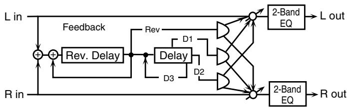
flowchart
graph TD
    A["L in"] --> B["+"]
    B --> C["+"]
    C --> D["Feedback"]
    D --> E["Rev. Delay"]
    E --> F["Delay"]
    F --> G["D1"]
    F --> H["D2"]
    G --> I["2-Band EQ"]
    H --> J["2-Band EQ"]
    I --> K["L out"]
    J --> L["R out"]
    M["R in"] --> N["+"]
    N --> O["+"]
    O --> P["Feedback"]
    P --> Q["Rev. Delay"]
    Q --> R["Delay"]
    R --> S["D3"]
    S --> T["2-Band EQ"]
    T --> U["R out"]
| Parameter | Range | Explanation |
| Threshold | 0–127 | Volume at which the reverse delay will begin to be applied |
| Rev Delay Time | 0–1300 ms, note | Delay time from when sound is input into the reverse delay until the delay sound is heard |
| Rev Delay Feedback # | -98– +98% | Proportion of the delay sound that is to be returned to the input of the reverse delay (negative values invert the phase) |
| Rev Delay HF Damp | 200–8000 Hz, BYPASS | Frequency at which the high-frequency content of the reverse-delayed sound will be cut (BYPASS: no cut) |
| Rev Delay Pan | L64–63R | Panning of the reverse delay sound |
| Rev Delay Level | 0–127 | Volume of the reverse delay sound |
| Delay 1 – 3 Time | 0–1300 ms, note | Delay time from when sound is input into the tap delay until the delay sound is heard |
| Delay 3 Feedback # | -98– +98% | Proportion of the delay sound that is to be returned to the input of the tap delay (negative values invert the phase) |
| Delay HF Damp | 200–8000 Hz, BY-PASS | Frequency at which the low-frequency content of the tap delay sound will be cut (BY-PASS: no cut) |
| Delay 1 Pan', 'Delay 2 Pan | L64–63R | Panning of the tap delay sounds |
| Delay 1 Level', 'Delay 2 Level | 0–127 | Volume of the tap delay sounds |
| Low Gain | -15– +15 dB | Amount of boost/cut for the low-frequency range |
| High Gain | -15– +15 dB | Amount of boost/cut for the high-frequency range |
| Balance # | D100:0W–D0:100W | Volume balance of the original sound (D) and delay sound (W) |
| Level | 0–127 | Output volume |
51: SHUFFLE DELAY
Adds a shuffle to the delay sound, giving the sound a bouncy delay effect with a swing feel.
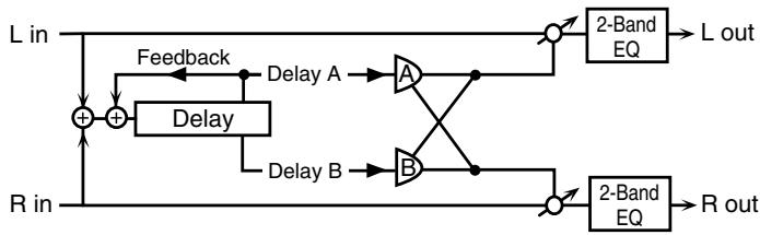
flowchart
graph TD
    L_in -->|Feedback| Delay1["Delay A"]
    R_in -->|Feedback| Delay2["Delay B"]
    Delay1 --> A["A"]
    Delay2 --> B["B"]
    A --> Out1["2-Band EQ"]
    B --> Out2["2-Band EQ"]
    Out1 --> L_out["L out"]
    Out2 --> R_out["R out"]
    L_in -->|+| Delay3["Delay"]
    R_in -->|+| Delay4["Delay"]
| Parameter | Value | Description |
| Delay Time # | 0–2600 ms, note | Adjusts the time until the delay sound is heard. |
| Shuffle Rate # | 0–100 % | Adjusts the ratio (as a percentage) of the time that elapses before Delay B sounds relative to the time that elapses before the Delay A sounds.When set to 100%, the delay times are the same. |
| Acceleration | 0–15 | Adjusts the time over which the Delay Time changes from the current setting to its specified new setting. |
| Feedback # | -98– +98 % | Adjusts the amount of the delay that's fed back into the effect. Negative (-) settings invert the phase. |
| HF Damp | 200–8000 Hz, BYPASS | Adjusts the frequency above which sound fed back to the effect is filtered out. If you don't want to filter out any high frequencies, set this parameter to BYPASS. |
| Pan A/B | 0–127 | Stereo location of Delay A/B |
| Level A/B | 0–127 | Volume of delay A/B |
| Low Gain | -15– +15 dB | Gain of the low frequency range |
| High Gain | -15– +15 dB | Gain of the high frequency range |
| Balance # | D100:0W–D0:100W | Volume balance between the direct sound (D) and the effect sound (W) |
| Level | 0–127 | Output level |
52: 3D DELAY
This applies a 3D effect to the delay sound. The delay sound will be positioned 90 degrees left and 90 degrees right.
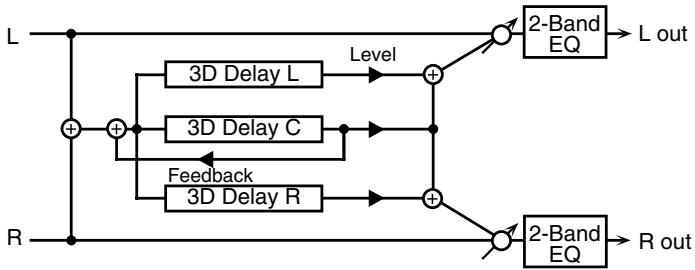
flowchart
graph TD
    L --> A["+"]
    R --> B["+"]
    A --> C["3D Delay L"]
    A --> D["3D Delay C"]
    A --> E["3D Delay R"]
    C --> F["Level"]
    D --> G["Feedback"]
    E --> H["+"]
    F --> I["2-Band EQ"]
    G --> J["2-Band EQ"]
    H --> K["2-Band EQ"]
    I --> L["L out"]
    J --> M["R out"]
| Parameter | Value | Description |
| Delay Left | 0–2600 ms, note | Adjusts the delay time from the direct sound until the delay sound is heard. |
| Delay Right | ||
| Delay Center | ||
| Center Feedback # | -98– +98 % | Adjusts the proportion of the delay sound that is fed back into the effect. Negative (-) settings will invert the phase. |
| HF Damp | 200–8000 Hz, BYPASS | Adjusts the frequency above which sound fed back to the effect will be cut. If you do not want to cut the high frequencies, set this parameter to BY-PASS. |
| Left Level | 0–127 | Output level of the delay sound |
| Right Level | ||
| Center Level | ||
| Output Mode | SPEAKER, PHONES | Adjusts the method that will be used to hear the sound that is output to the OUTPUT jacks. The optimal 3D effect will be achieved if you select SPEAKER when using speakers, or PHONES when using headphones. |
| Low Gain | -15– +15 dB | Gain of the low range |
| High Gain | -15– +15 dB | Gain of the high range |
| Balance # | D100:0W–D0:100W | Volume balance between the direct sound (D) and the effect sound (W) |
| Level | 0–127 | Output Level |
53: TIME CTRL DELAY
A stereo delay in which the delay time can be varied smoothly.
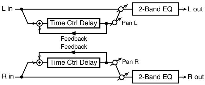
flowchart
graph TD
    A["L in"] --> B["+"]
    B --> C["Time Ctrl Delay"]
    C --> D["Pan L"]
    D --> E["2-Band EQ"]
    E --> F["L out"]
    G["R in"] --> H["+"]
    H --> I["Time Ctrl Delay"]
    I --> J["Pan R"]
    J --> K["2-Band EQ"]
    K --> L["R out"]
    B --> M["Feedback"]
    I --> N["Feedback"]
    M --> C
    N --> D
| Parameter | Value | Description |
| Delay Time # | 0–1300 ms, note | Adjusts the time until the delay is heard. |
| Acceleration | 0–15 | Adjusts the time over which the Delay Time changes from the current setting to a specified new setting.The rate of change for the Delay Time directly affects the rate of pitch change. |
| Feedback # | -98– +98 % | Adjusts the amount of the delay that’s fed back into the effect.Negative (-) settings invert the phase. |
| HF Damp | 200–8000 Hz,BYPASS | Adjusts the frequency above which sound fed back to the effect is filtered out. If you do not want to filter out any high frequencies, set this parameter to BYPASS. |
| Low Gain | -15– +15 dB | Gain of the low frequency range |
| High Gain | -15– +15 dB | Gain of the high frequency range |
| Balance # | D100:0W–D0:100W | Volume balance between the direct sound (D) and the delay sound (W) |
| Level | 0–127 | Output level |
54: LONG TIME CTRL DELAY
A delay in which the delay time can be varied smoothly, and allowing an extended delay to be produced.
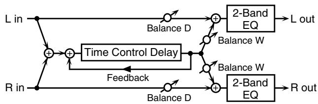
flowchart
graph TD
    L_in --> A["+"]
    R_in --> B["+"]
    A --> C["Balance D"]
    B --> D["Balance D"]
    C --> E["+"]
    D --> F["+"]
    E --> G["2-Band EQ"]
    F --> H["2-Band EQ"]
    G --> I["L out"]
    H --> J["R out"]
    K["Time Control Delay"] --> E
    K --> F
    K --> H
    L -->|Feedback| K
| Parameter | Value | Description |
| Delay Time # | 0–2600 ms, note | Adjusts the time until the delay is heard. |
| Acceleration | 0–15 | Adjusts the time over which the Delay Time changes from the current setting to a specified new setting.The rate of change for the Delay Time directly affects the rate of pitch change. |
| Feedback # | -98– +98 % | Adjusts the amount of the delay that's fed back into the effect. Negative (-) settings invert the phase. |
| HF Damp | 200–8000 Hz, BYPASS | Adjusts the frequency above which sound fed back to the effect is filtered out. If you do not want to filter out any high frequencies, set this parameter to BYPASS. |
| Pan # | L64–63R | Stereo location of the delay |
| Low Gain | -15– +15 dB | Gain of the low frequency range |
| High Gain | -15– +15 dB | Gain of the high frequency range |
| Balance # | D100:0W–D0:100W | Volume balance between the direct sound (D) and the delay sound (W) |
| Level | 0–127 | Output level |
55: TAPE ECHO
A virtual tape echo that produces a realistic tape delay sound. This simulates the tape echo section of a Roland RE-201 Space Echo.
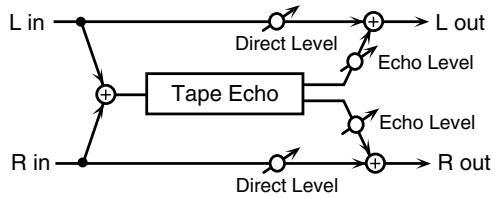
flowchart
graph LR
    L_in --> A["+"]
    R_in --> B["+"]
    A --> C["Tape Echo"]
    B --> C
    C --> D["+"]
    E_Lout --> F["+"]
    G_Rout --> H["+"]
    I_Lin --> J["Direct Level"]
    J --> K["Echo Level"]
    K --> L
    M["Rin"] --> N["Direct Level"]
    N --> O["Echo Level"]
    O --> P
    Q["Lout"] --> R
    S["Rout"] --> T
| Parameter | Value | Description |
| Mode | S, M, L,S+M, S+L,M+L,S+M+L | Combination of playback heads to useSelect from three different heads withdifferent delay times.S: short M: middle L: long |
| Repeat Rate # | 0–127 | Tape speedIncreasing this value will shorten thespacing of the delayed sounds. |
| Intensity # | 0–127 | Amount of delay repeats |
| Bass | -15– +15 dB | Boost/cut for the lower range of the echo sound |
| Treble | -15– +15 dB | Boost/cut for the upper range of the echo sound |
| Head S Pan | L64–63R | Independent panning for the short, mid-dle, and long playback heads |
| Head M Pan | ||
| Head L Pan | ||
| Tape Distortion | 0–5 | Amount of tape-dependent distortion to be addedThis simulates the slight tonal changes that can be detected by signal-analysis equipment. Increasing this value will increase the distortion. |
| Parameter | Value | Description |
| Wow/Flutter Rate | 0–127 | Speed of wow/flutter (complex variation in pitch caused by tape wear and rotational irregularity) |
| Wow/Flutter Depth | 0–127 | Depth of wow/flutter |
| Echo Level # | 0–127 | Volume of the echo sound |
| Direct Level # | 0–127 | Volume of the original sound |
| Level | 0–127 | Output level |
56: LOFI NOISE
In addition to a lo-fi effect, this adds various types of noise such as white noise and disc noise.
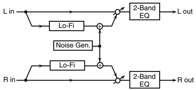
flowchart
graph TD
    A["L in"] --> B["Lo-Fi"]
    B --> C["+"]
    D["R in"] --> E["Lo-Fi"]
    E --> F["+"]
    C --> G["2-Band EQ"]
    F --> H["2-Band EQ"]
    G --> I["L out"]
    H --> J["R out"]
    K["Noise Gen."] --> C
    K --> F
| Parameter | Value | Description |
| LoFi Type | 1-9 | Degrades the sound quality. The sound quality grows poorer as this value is increased. |
| Post Filter Type | OFF, LPF, HPF | Type of filterOFF: no filter is usedLPF: cuts the frequency range above the CutoffHPF: cuts the frequency range below the Cutoff |
| Post Filter Cutoff | 200-8000 Hz | Center frequency of the filter |
| W/P Noise Type | WHITE, PINK | Switch between white noise and pink noise. |
| W/P Noise LPF | 200-8000 Hz, BYPASS | Center frequency of the low pass filter applied to the white/pink noise (BY-PASS: no cut) |
| W/P Noise Level # | 0-127 | Volume of the white/pink noise |
| Disc Noise Type | LP, EP, SP, RND | Type of record noiseThe frequency at which the noise is heard depends on the selected type. |
| Disc Noise LPF | 200-8000 Hz, BYPASS | Adjusts the cutoff frequency of the low pass filter applied to the record noise. If you don’t want to filter out any high frequencies, set this parameter to BYPASS. |
| Disc Noise Level # | 0-127 | Volume of the record noise |
| Hum Noise Type | 50 Hz, 60 Hz | Frequency of the hum noise |
| Hum Noise LPF | 200-8000 Hz, BYPASS | Center frequency of the low pass filter applied to the hum noise (BYPASS: no cut) |
| Hum Noise Level # | 0-127 | Volume of the hum noise |
| Low Gain | -15- +15 dB | Gain of the low range |
| High Gain | -15- +15 dB | Gain of the high range |
| Balance # | D100:0W-D0:100W | Volume balance between the direct sound (D) and the effect sound (W) |
| Level | 0-127 | Output level |
57: LOFI COMPRESS
This is an effect that intentionally degrades the sound quality for creative purposes.
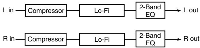
flowchart
graph LR
    A["L in"] --> B["Compressor"]
    B --> C["Lo-Fi"]
    C --> D["2-Band EQ"]
    D --> E["L out"]
    F["R in"] --> G["Compressor"]
    G --> H["Lo-Fi"]
    H --> I["2-Band EQ"]
    I --> J["R out"]
| Parameter | Value | Description |
| Pre Filter Type | 1-6 | Selects the type of filter applied to the sound before it passes through the Lo-Fi effect. |
| LoFi Type | 1-9 | Degrades the sound quality. The sound quality grows poorer as this value is increased. |
| Post Filter Type | OFF, LPF, HPF | Type of filterOFF: no filter is usedLPF: cuts the frequency range above the CutoffHPF: cuts the frequency range below the Cutoff |
| Post Filter Cutoff | 200-8000 Hz | Basic frequency of the Post Filter |
| Low Gain | -15- +15 dB | Gain of the low range |
| High Gain | -15- +15 dB | Gain of the high range |
| Balance # | D100:0W-D0:100W | Volume balance between the direct sound (D) and the effect sound (W) |
| Level # | 0-127 | Output level |
58: LOFI RADIO
In addition to a Lo-Fi effect, this effect also generates radio noise.
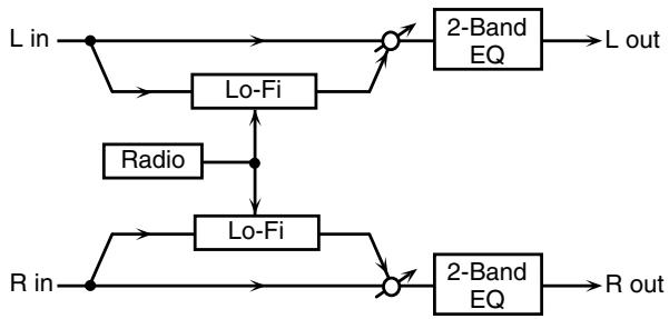
flowchart
graph TD
    A["L in"] --> B["Lo-Fi"]
    B --> C["2-Band EQ"]
    C --> D["L out"]
    E["R in"] --> F["Lo-Fi"]
    F --> G["2-Band EQ"]
    G --> H["R out"]
    I["Radio"] --> J["Lo-Fi"]
    J --> F
    B --> K["Circle"]
    F --> L["Circle"]
| Parameter | Value | Description |
| LoFi Type | 1-9 | Degrades the sound quality. The sound quality grows poorer as this value is increased. |
| Post Filter Type | OFF, LPF, HPF | Type of filterOFF: no filter is usedLPF: cuts the frequency range above the CutoffHPF: cuts the frequency range below the Cutoff |
| Post Filter Cutoff | 200-8000 Hz | Basic frequency of the Post Filter |
| Radio Detune # | 0-127 | Simulates the tuning noise of a radio. As this value is raised, the tuning drifts further. |
| Radio Noise Level # | 0-127 | Volume of the radio noise |
| Balance # | D100:0W-D0:100W | Volume balance between the direct sound (D) and the effect sound (W) |
| Level | 0-127 | Output level |
59: TELEPHONE
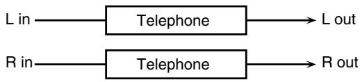
flowchart
graph LR
    A["L in"] --> B["Telephone"]
    C["R in"] --> D["Telephone"]
    B --> E["L out"]
    D --> F["R out"]
| Parameter | Value | Description |
| Voice Quality # | 0-15 | Audio quality of the telephone voice |
| Treble | -15- +15 dB | Bandwidth of the telephone voice |
| Balance # | D100:0-D0:100W | Volume balance between the direct sound (D) and the effect sound (W) |
| Level | 0-127 | Output level |
60: PHONOGRAPH
Simulates a sound recorded on an analog record and played back on a record player. This effect also simulates the various types of noise that are typical of a record, and even the rotational irregularities of an old turntable.
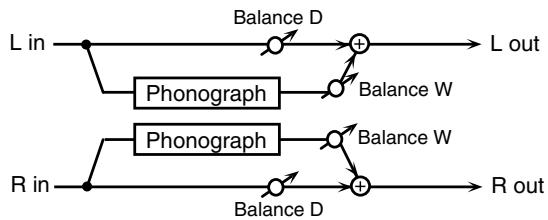
flowchart
graph LR
    L_in --> A["Phonograph"]
    A --> B["Balance D"]
    B --> C["L out"]
    R_in --> D["Phonograph"]
    D --> E["Balance W"]
    E --> F["R out"]
    A --> G["Balance D"]
    G --> H["+"]
    H --> C
    D --> I["Balance D"]
    I --> J["+"]
    J --> C
| Parameter | Value | Description |
| Signal Distortion | 0–127 | Depth of distortion |
| Frequency Range | 0–127 | Frequency response of the playback systemDecreasing this value will produce the impression of an old system with a poor frequency response. |
| Disc Type | LP, EP, SP | Rotational speed of the turntableThis will affect the frequency of the scratch noise. |
| Scratch Noise Level | 0–127 | Amount of noise due to scratches on the record |
| Dust Noise Level | 0–127 | Volume of noise due to dust on the record |
| Hiss Noise Level | 0–127 | Volume of continuous “hiss” |
| Total Noise Level # | 0–127 | Volume of overall noise |
| Wow | 0–127 | Depth of long-cycle rotational irregularity |
| Flutter | 0–127 | Depth of short-cycle rotational irregularity |
| Random | 0–127 | Depth of indefinite-cycle rotational irregularity |
| Total Wow/Flutter # | 0–127 | Depth of overall rotational irregularity |
| Balance # | D100:0W–D0:100W | Volume balance between the direct sound (D) and the effect sound (W) |
| Level | 0–127 | Output level |
61: PITCH SHIFTER (Feedback Pitch Shifter)
A stereo pitch shifter.
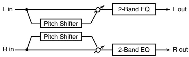
flowchart
graph LR
    L_in --> A["Node"]
    A --> B["Pitch Shifter"]
    B --> C["Node"]
    C --> D["2-Band EQ"]
    D --> E["L out"]
    R_in --> F["Node"]
    F --> G["Pitch Shifter"]
    G --> H["Node"]
    H --> I["2-Band EQ"]
    I --> J["R out"]
| Parameter | Value | Description |
| Coarse #1 | -24– +12 semi | Adjusts the pitch of the pitch shifted sound in semitone steps. |
| Fine #1 | -100– +100 cent | Adjusts the pitch of the pitch shifted sound in 2-cent steps. |
| Delay Time | 0–1300 ms, note | Adjusts the delay time from the direct sound until the pitch shifted sound is heard. |
| Feedback # | -98– +98 % | Adjusts the proportion of the pitch shifted sound that is fed back into the effect. Negative (-) settings will invert the phase. |
| Low Gain | -15– +15 dB | Gain of the low range |
| High Gain | -15– +15 dB | Gain of the high range |
| Balance # | D100:0W–D0:100W | Volume balance between the direct sound (D) and the pitch shifted sound (W) |
| Level | 0–127 | Output Level |
62: 2VOICE PITCH SHIFTER
Shifts the pitch of the original sound. This 2-voice pitch shifter has two pitch shifters, and can add two pitch shifted sounds to the original sound.
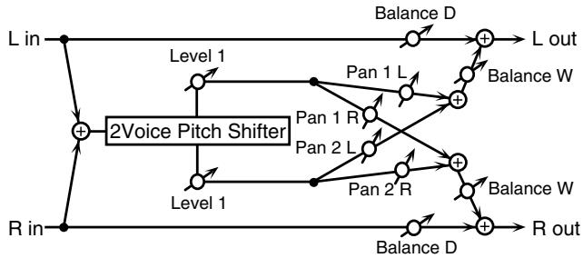
flowchart
graph TD
    L_in --> +1["+"]
    R_in --> +1
    +1 --> Level1["Level 1"]
    +1 --> Level2["Level 1"]
    +1 --> Level3["Level 1"]
    Level1 --> Pan1L["Pan 1 L"]
    Level2 --> Pan2L["Pan 2 L"]
    Level3 --> Pan2R["Pan 2 R"]
    +1 --> BalanceD["Balance D"]
    +1 --> BalanceW["Balance W"]
    +1 --> Rout["R out"]
    +1 --> Lout["L out"]
    +1 --> Rout
    +1 --> Lout
    +1 --> Lout
    +1 --> Lout
    +1 --> Lout
    +1 --> Lout
    +1 --> Lout
    +1 --> Lout
    +1 --> Lout
    +1 --> Lout
    +1 --> Lout
    +1 --> Lout
    +1 --> Lout
    +1 --> Lout
    +1 --> Lout
    +1 --> Lout

    subgraph '2Voice Pitch Shifter'
        L_in --> +1
        R_in --> +1
        L_in --> +2
        R_in --> +2
        L_in --> +3
        R_in --> +3
        L_in --> +4
        R_in --> +4
        L_in --> +5
        R_in --> +5
        L_in --> +6
        R_in --> +6
        L_in --> +7
        R_in --> +7
        L_in --> +8
        R_in --> +8
        L_in --> +9
        R_in --> +9
        L_in --> +10
        R_in --> +10
        L_in --> +11
        R_in --> +11
        L_in --> +12
        R_in --> +12
        L_in --> +13
        R_in --> +13
        L_in --> +14
        R_in --> +14
        L_in --> +15
        R_in --> +15
        L_in --> +16
        R_in --> +16
        L_in --> +17
        R_in --> +17
        L_in --> +18
        R_in --> +18
        L_in --> +19
        R_in --> +19
        L_in --> +20
        R_in --> +20
        L_in --> +21
        R_in --> +21
        L_in --> +22
        R_in --> +22
        L_in --> +23
        R_in --> +23
        L_in --> +24
        R_in --> +24
        L_in --> +25
        R_in --> +25
        L_in --> +26
        R_in --> +26
        L_in --> +27
        R_in --> +27
        L_in --> +28
        R_in --> +28
        L_in --> +29
        R_in --> +29
        L_in --> +30
        R_in --> +30
        L_in --> +31
        R_in --> +31
        L_in --> +32
        R_in --> +32
        L_in --> +33
        R_in --> +33
        L_in --> +34
        R_in --> +34
        L_in --> +35
        R_in --> +35
        L_in --> +36
        R_in --> +36
        L_in --> +37
        R_in --> +37
        L_in --> +38
        R_in --> +38
        L_in --> +39
        R_in --> +39
        L_in --> +40
        R_in --> +40
        L_in --> +41
        R_in --> +41
        L_in --> +42
        R_in --> +42
        L_in --> +43
        R_in --> +43
        L_in --> +44
        R_in --> +44
        L_in --> +45
        R_in --> +45
        L_in --> +46
        R_in --> +46
        L_in --> +47
        R_in --> +47
        L_in --> +48
        R_in --> +48
        L_in --> +49
        R_in --> +49
        L_in --> +50
        R_in --> +50

    subgraph '2Voice Pitch Shifter'
        -Level1["Level 1"] & -Level2["Level 2"] & -Level3["Level 3"]
    end

    style -Level1 fill:#f9f,stroke:#333,stroke-width:2px;
    style -Level2 fill:#f9f,stroke:#333,stroke-width:2px;
    style -Level3 fill:#f9f,stroke:#333,stroke-width:2px;
    style -Level4 fill:#f9f,stroke:#333,stroke-width:2px;
    style -Level5 fill:#f9f,stroke:#333,stroke-width:2px;
    style -Level6 fill:#f9f,stroke:#333,stroke-width:2px;
    style -Level7 fill:#f9f,stroke:#333,stroke-width:2px;
    style -Level8 fill:#f9f,stroke:#333,stroke-width:2px;
    style -Level9 fill:#f9f,stroke:#333,stroke-width:2px;
    style -Level10 fill:#f9f,stroke:#333,stroke-width:2px;
    style -Level11 fill:#f9f,stroke:#333,stroke-width:2px;
    style -Level12 fill:#f9f,stroke:#333,stroke-width:2px;
    style -Level13 fill:#f9f,stroke:#333,stroke-width:2px;
    style -Level14 fill:#f9f,stroke:#333,stroke-width:2px;
    style -Level15 fill:#f9f,stroke:#333,stroke-width:2px;
    style -Level16 fill:#f9f,stroke:#333,stroke-width:2px;
    style -Level17 fill:#f9f,stroke:#333,stroke-width:2px;
    style -Level18 fill:#f9f,stroke:#333,stroke-width:2px;
    style -Level19 fill:#f9f,stroke:#333,stroke-width:2px;
    style -Level20 fill:#f9f,stroke:#333,stroke-width:2px;
    style -Level21 fill:#f9f,stroke:#333,stroke-width:2px;
    style -Level22 fill:#f9f,stroke:#333,stroke-width:2px;
    style -Level23 fill:#f9f,stroke:#333,stroke-width:2px;
    style -Level24 fill:#f9f,stroke:#333,stroke-width:2px;
    style -Level25 fill:#f9f,stroke:#333,stroke-width:2px;
    style -Level26 fill:#f9f,stroke:#333,stroke-width:2px;
    style -Level27 fill:#f9f,stroke:#333,stroke-width:2px;
    style -Level28 fill:#f9f,stroke:#333,stroke-width:2px;
    style -Level29 fill:#f9f,stroke:#333,stroke-width:2px;
    style -Level30 fill:#f9f,stroke:#333,stroke-width:2px;
    style -Level31 fill:#f9f,stroke:#333,stroke-width:2px;
    style -Level32 fill:#f9f,stroke:#333,stroke-width:2px;
    style -Level33 fill:#f9f,stroke:#333,stroke-width:2px;
    style -Level34 fill:#f9f,stroke:#333,stroke-width:2px;
    style -Level35 fill:#f9f,stroke:#333,stroke-width:2px;
    style -Level36 fill:#f9f,stroke:#333,stroke-width:2px;
    style -Level37 fill:#f9f,stroke:#333,stroke-width:2px;
    style -Level38 fill:#f9f,stroke:#333,stroke-width:2px;
    style -Level39 fill:#f9f,stroke:#333,stroke-width:2px;
    style -Level40 fill:#f9f,stroke:#333,stroke-width:2px;
    style -Level41 fill:#f9f,stroke:#333,stroke-width:2px;
    style -Level42 fill:#f9f,stroke:#333,stroke-width:2px;
    style -Level43 fill:#f9f,stroke:#333,stroke-width:2px;
    style -Level44 fill:#f9f,stroke:#333,stroke-width:2px;
    style -Level45 fill:#f9f,stroke:#333,stroke-width:2px;
    style -Level46 fill:#f9f,stroke:#333,stroke-width:2px;
    style -Level47 fill:#f9f,stroke:#333,stroke-width:2px;
    style -Level48 fill:#f9f,stroke:#333,stroke-width:2px;
    style -Level49 fill:#f9f,stroke:#333,stroke-width:2px;
    style -Level50 fill:#f9f,stroke:#333,stroke-width:2px;
    style -Level51 fill:#f9f,stroke:#333,stroke-width:2px;
    style -Level52 fill:#f9f,stroke:#333,stroke-width:2px;
    style -Level53 fill:#f9f,stroke:#333,stroke-width:2px;
    style -Level54 fill:#f9f,stroke:#333,stroke-width:2px;
    style -Level55 fill:#f9f,stroke:#�0000000000000000000000000000000000000000000000000000000000000000000000000000000000000000000000000000 |
| Parameter | Value | Description |
| Pitch 1: Coarse #1 | -24-+12 semi | Adjusts the pitch of Pitch Shift 1 in semitone steps. |
| Pitch 1:Fine #1 | -100-+100 cent | Adjusts the pitch of Pitch Shift Pitch 1 in 2-cent steps. |
| Pitch 1:Delay | 0-1300 ms, note | Adjusts the delay time from the direct sound until the Pitch Shift 1 sound is heard. |
| Pitch 1:Feedback # | -98- +98 % | Adjusts the proportion of the pitch shifted sound that is fed back into the effect. Negative (-) settings will invert the phase. |
| Pitch 1:Pan # | L64-63R | Stereo location of the Pitch Shift 1 sound |
| Pitch 1:Level | 0-127 | Volume of the Pitch Shift1 sound |
| Pitch 2: Coarse #2 | -24-+12 semi | Settings of the Pitch Shift 2 sound.The parameters are the same as for the Pitch Shift 1 sound. |
| Pitch 2:Fine #2 | -100-+100 cent | |
| Pitch 2:Delay | 0-1300 ms, note | |
| Pitch 2:Feedback # | -98- +98 % | |
| Pitch 2:Pan # | L64-63R | |
| Pitch 2:Level | 0-127 | |
| Low Gain | -15- +15 dB | Gain of the low range |
| Parameter | Value | Description |
| High Gain | -15– +15 dB | Gain of the high range |
| Level Balance | A100:0B-A0:100B | Volume balance between the Pitch Shift 1 and Pitch Shift 2 sounds |
| Balance | D100:0W-D0:100W | Volume balance between the direct sound (D) and the pitch shifted sound (W) |
| Level | 0-127 | Output Level |
63: STEP PITCH SHIFTER
A pitch shifter in which the amount of pitch shift is varied by a 16-step sequence.
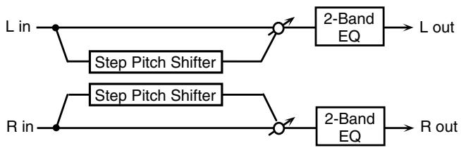
flowchart
graph LR
    A["L in"] --> B["Step Pitch Shifter"]
    B --> C["2-Band EQ"]
    C --> D["L out"]
    E["R in"] --> F["Step Pitch Shifter"]
    F --> G["2-Band EQ"]
    G --> H["R out"]
| Parameter | Range | Explanation |
| Step 01–16 | -24– +12 semi | Amount of pitch shift at each step (semitone units) |
| Rate # | 0.05–10.00 Hz, note | Rate at which the 16-step sequence will cycle |
| Attack # | 0–127 | Speed at which the amount of pitch shift changes between steps |
| Gate Time # | 0–127 | Duration of the pitch shifted sound at each step |
| Fine | -100– +100 cent | Pitch shift adjustment for all steps (2-cent units) |
| Delay Time | 0–1300 ms, note | Delay time from the original sound until the pitch-shifted sound is heard |
| Feedback # | -98– +98% | Proportion of the pitch-shifted sound that is to be returned to the input (negative values invert the phase) |
| Low Gain | -15– +15 dB | Amount of boost/cut for the low-frequency range |
| High Gain | -15– +15 dB | Amount of boost/cut for the high-frequency range |
| Balance # | D100:0W–D0:100W | Volume balance of the original sound (D) and pitch-shifted sound (W) |
| Level | 0–127 | Output volume |
64: OVERDRIVE → CHORUS
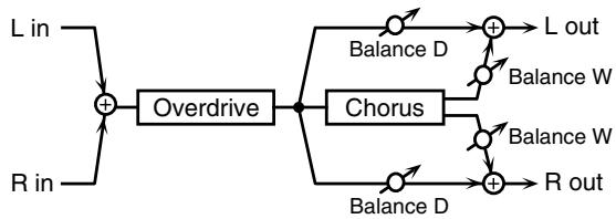
flowchart
graph TD
    A["L in"] --> B["+"]
    C["R in"] --> B
    B --> D["Overdrive"]
    D --> E["Chorus"]
    E --> F["Balance D"]
    E --> G["Balance W"]
    E --> H["Balance W"]
    E --> I["Balance D"]
    E --> J["Balance W"]
    E --> K["R out"]
    F --> L["L out"]
    G --> M["R out"]
| Parameter | Value | Description |
| Overdrive Drive # | 0–127 | Degree of distortionAlso changes the volume. |
| Overdrive Pan # | L64–63R | Stereo location of the overdrive sound |
| Chorus Pre Delay | 0.0–100.0 ms | Adjusts the delay time from the direct sound until the chorus sound is heard. |
| Chorus Rate # | 0.05–10.00 Hz, note | Frequency of modulation |
| Chorus Depth | 0–127 | Depth of modulation |
| Chorus Balance # | D100:0W–D0:100W | Adjusts the volume balance between the sound that is sent through the chorus (W) and the sound that is not sent through the chorus (D). |
| Level | 0–127 | Output Level |
65: OVERDRIVE → FLANGER
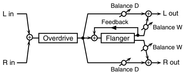
flowchart
graph TD
    A["L in"] --> B["+"]
    C["R in"] --> B
    B --> D["Overdrive"]
    D --> E["+"]
    F["Balance D"] --> G["+"]
    H["Balance W"] --> I["+"]
    J["Balance W"] --> K["+"]
    L["Balance D"] --> M["+"]
    N["Balance D"] --> O["+"]
    P["R out"] --> Q["+"]
    R["Feedback"] --> S["Flanger"]
    S --> D
    T["L out"] --> G
| Parameter | Value | Description |
| Overdrive Drive # | 0–127 | Degree of distortionAlso changes the volume. |
| Overdrive Pan # | L64–63R | Stereo location of the overdrive sound |
| Flanger Pre Delay | 0.0–100.0 ms | Adjusts the delay time from when the direct sound begins until the flanger sound is heard. |
| Flanger Rate # | 0.05–10.00 Hz, note | Frequency of modulation |
| Flanger Depth | 0–127 | Depth of modulation |
| Flanger Feedback # | -98–+98 % | Adjusts the proportion of the flanger sound that is fed back into the effect. Negative (-) settings will invert the phase. |
| Flanger Balance # | D100:0W–D0:100W | Adjusts the volume balance between the sound that is sent through the flanger (W) and the sound that is not sent through the flanger (D). |
| Level | 0–127 | Output Level |
66: OVERDRIVE → DELAY
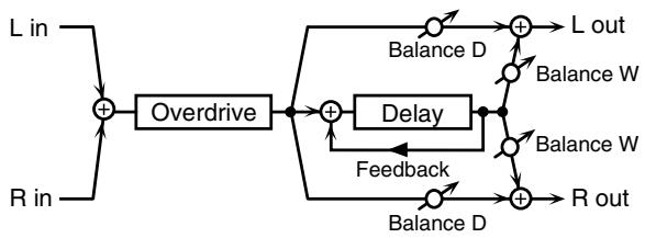
flowchart
graph TD
    A["L in"] --> B["+"]
    C["R in"] --> B
    B --> D["Overdrive"]
    D --> E["+"]
    F["Balance D"] --> G["+"]
    H["Balance W"] --> I["+"]
    J["Balance W"] --> K["+"]
    L["Balance D"] --> M["+"]
    N["Balance D"] --> O["+"]
    P["Feedback"] --> Q["+"]
    R["L out"] --> S["+"]
    T["R out"] --> U["+"]
| Parameter | Value | Description |
| Overdrive Drive # | 0–127 | Degree of distortionAlso changes the volume. |
| Overdrive Pan # | L64–63R | Stereo location of the over-drive sound |
| Delay Time | 0–2600 ms, note | Adjusts the delay time from the direct sound until the delay sound is heard. |
| Delay Feedback # | -98– +98 % | Adjusts the proportion of the delay sound that is fed back into the effect. Negative (-) settings will invert the phase. |
| Delay HF Damp | 200–8000 Hz, BYPASS | Adjusts the frequency above which sound fed back to the effect will be cut. If you do not want to cut the high frequencies, set this parameter to BY-PASS. |
| Delay Balance # | D100:0W–D0:100W | Adjusts the volume balance between the sound that is sent through the delay (W) and the sound that is not sent through the delay (D). |
| Parameter | Value | Description |
| Level | 0–127 | Output Level |
67: DISTORTION → CHORUS
The parameters are essentially the same as in “64: OVERDRIVE → CHORUS,” with the exception of the following two.
Overdrive Drive → Distortion Drive, Overdrive Pan → Distortion Pan
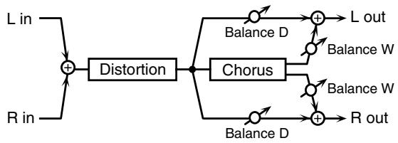
flowchart
graph TD
    A["L in"] --> B["+"]
    C["R in"] --> B
    B --> D["Distortion"]
    D --> E["Chorus"]
    E --> F["Balance D"]
    E --> G["Balance W"]
    E --> H["Balance W"]
    E --> I["Balance D"]
    E --> J["Balance W"]
    E --> K["R out"]
    F --> L["L out"]
    G --> M["R out"]
68: DISTORTION → FLANGER
The parameters are essentially the same as in “65: OVERDRIVE → FLANGER,” with the exception of the following two.
Overdrive Drive → Distortion Drive, Overdrive Pan → Distortion Pan

flowchart
graph TD
    A["L in"] --> B["+"]
    C["R in"] --> B
    B --> D["Distortion"]
    D --> E["+"]
    F["Balance D"] --> G["+"]
    H["Balance W"] --> I["+"]
    J["Balance W"] --> K["+"]
    L["Balance D"] --> M["+"]
    N["Balance W"] --> O["+"]
    P["R out"] --> Q["+"]
    G --> R["L out"]
    I --> S["Balance W"]
    K --> T["Balance W"]
    Q --> U["Balance D"]
    V["Feedback"] --> G
    V --> I
    V --> K
69: DISTORTION → DELAY
The parameters are essentially the same as in "66: OVERDRIVE → DELAY," with the exception of the following two.
Overdrive Drive → Distortion Drive, Overdrive Pan → Distortion Pan
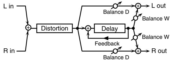
flowchart
graph TD
    A["L in"] --> B["+"]
    C["R in"] --> B
    B --> D["Distortion"]
    D --> E["+"]
    F["Balance D"] --> G["+"]
    H["Balance W"] --> I["+"]
    J["Balance W"] --> K["+"]
    L["Balance D"] --> M["+"]
    N["Balance D"] --> O["+"]
    P["Feedback"] --> Q["+"]
    R["R out"] --> S["+"]
    T["L out"] --> G
    U["R out"] --> V["+"]
70: ENHANCER → CHORUS
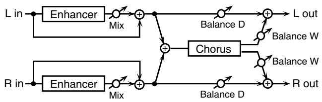
flowchart
graph LR
    L_in --> Enhancer1["Enhancer"]
    R_in --> Enhancer2["Enhancer"]
    L_in --> Mix1["Mix"]
    R_in --> Mix2["Mix"]
    Mix1 --> Add1["+"]
    Mix2 --> Add2["+"]
    Add1 --> Chorus["Chorus"]
    Add2 --> Chorus
    Chorus --> L_out["L out"]
    Chorus --> R_out["R out"]
    Balance_D["Balance D"] --> Add1
    Balance_W["Balance W"] --> Add2
    Balance_D --> Add3["+"]
    Balance_W --> Add4["+"]
    Balance_D --> Add5["+"]
    Balance_W --> Add5
    R_in --> Add6["+"]
    L_in --> Add7["+"]
    R_in --> Add8["+"]
| Parameter | Value | Description |
| Enhancer Sens # | 0–127 | Sensitivity of the enhancer |
| Enhancer Mix # | 0–127 | Level of the overtones generated by the enhancer |
| Chorus Pre Delay | 0.0–100.0 ms | Adjusts the delay time from the direct sound until the chorus sound is heard. |
| Chorus Rate # | 0.05–10.00 Hz, note | Frequency of modulation |
| Chorus Depth | 0–127 | Depth of modulation |
| Chorus Balance # | D100:0W–D0:100W | Adjusts the volume balance between the sound that is sent through the chorus (W) and the sound that is not sent through the chorus (D). |
| Level | 0–127 | Output Level |
| Parameter | Value | Description |
| Enhancer Sens # | 0–127 | Sensitivity of the enhancer |
| Enhancer Mix # | 0–127 | Level of the overtones generated by the enhancer |
| Flanger Pre Delay | 0.0–100.0 ms | Adjusts the delay time from when the direct sound begins until the flanger sound is heard. |
| Flanger Rate # | 0.05–10.00 Hz, note | Frequency of modulation |
| Flanger Depth | 0–127 | Depth of modulation |
| Flanger Feedback # | -98– +98 % | Adjusts the proportion of the flanger sound that is fed back into the effect. Negative (-) settings will invert the phase. |
| Flanger Balance # | D100:0W–D0:100W | Adjusts the volume balance between the sound that is sent through the flanger (W) and the sound that is not sent through the flanger (D). |
| Level | 0–127 | Output Level |
72: ENHANCER → DELAY
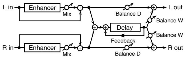
flowchart
graph TD
    A["L in"] --> B["Enhancer"]
    B --> C["Mix"]
    C --> D["+"]
    D --> E["Balance D"]
    E --> F["L out"]
    G["R in"] --> H["Enhancer"]
    H --> I["Mix"]
    I --> J["+"]
    J --> K["Balance D"]
    K --> L["+"]
    L --> M["R out"]
    N["Delay"] --> O["Feedback"]
    P["Balance W"] --> Q["+"]
    R["Balance W"] --> S["+"]
    T["Balance D"] --> U["+"]
    V["Balance D"] --> W["+"]
    X["Balance D"] --> Y["+"]
    Z["Balance D"] --> AA["+"]
    AB["Balance D"] --> AC["+"]
    AD["Balance D"] --> AE["+"]
    AF["Balance D"] --> AG["+"]
    AH["Balance D"] --> AI["+"]
    AJ["Balance D"] --> AK["+"]
    AL["Balance D"] --> AM["+"]
    AN["Balance D"] --> AO["+"]
    AP["Balance D"] --> AQ["+"]
    AR["Balance D"] --> AS["+"]
    AT["Balance D"] --> AU["+"]
    AV["Balance D"] --> AW["+"]
    AX["Balance D"] --> AY["+"]
    AZ["Balance D"] --> BA["+"]
    BB["Balance D"] --> BC["+"]
    BD["Balance D"] --> BE["+"]
    BF["Balance D"] --> BG["+"]
    BH["Balance D"] --> BI["+"]
    BJ["Balance D"] --> BK["+"]
    BL["Balance D"] --> BM["+"]
    BN["Balance D"] --> BO["+"]
    BP["Balance D"] --> BQ["+"]
    BR["Balance D"] --> BS["+"]
    BT["Balance D"] --> BU["+"]
    BV["Balance D"] --> BW["+"]
    BX["Balance D"] --> BY["+"]
    BZ["Balance D"] --> CA["+"]
    CB["Balance D"] --> CC["+"]
    CD["Balance D"] --> CE["+"]
    CF["Balance D"] --> CG["+"]
    CH["Balance D"] --> CI["+"]
    CJ["Balance D"] --> CK["+"]
    CL["Balance D"] --> CM["+"]
    CN["Balance D"] --> CO["+"]
    CP["Balance D"] --> CS["+"]
    CT["Balance D"] --> CU["+"]
    CV["Balance D"] --> CW["+"]
    CX["Balance D"] --> CY["+"]
    CZ["Balance D"] --> DA["+"]
    DB["Balance D"] --> DC["+"]
    DD["Balance D"] --> DJ["+"]
    DK["Balance D"] --> DL["+"]
    DV["Balance D"] --> DW["+"]
    DX["Balance D"] --> DXB["+"]
    DXB --> DXC["-"]
    DXC --> DXD["-"]
    DXD --> DXE["-"]
    DXE --> DXF["-"]
    DXF --> DXG["-"]
    DXG --> DXH["-"]
    DXH --> DXI["-"]
    DXI --> DXJ["-"]
    DXJ --> DXK["-"]
| Parameter | Value | Description |
| Enhancer Sens # | 0–127 | Sensitivity of the enhancer |
| Parameter | Value | Description |
| Enhancer Mix # | 0–127 | Level of the overtones generated by the enhancer |
| Delay Time | 0–2600 ms, note | Adjusts the delay time from the direct sound until the delay sound is heard. |
| Delay Feedback # | -98– +98 % | Adjusts the proportion of the delay sound that is fed back into the effect. Negative (-) settings will invert the phase. |
| Delay HF Damp | 200–8000 Hz, BYPASS | Adjusts the frequency above which sound fed back to the effect will be cut. If you do not want to cut the high frequencies, set this parameter to BY-PASS. |
| Delay Balance # | D100:0W–D0:100W | Adjusts the volume balance between the sound that is sent through the delay (W) and the sound that is not sent through the delay (D). |
| Level | 0–127 | Output Level |
73: CHORUS → DELAY
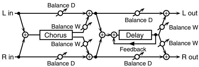
flowchart
graph LR
    L_in -->|Balance D| +1["+"]
    R_in -->|Balance D| +2["+"]
    +1 -->|Balance W| +3["+"]
    +2 -->|Balance W| +4["+"]
    +3 -->|Balance D| +5["+"]
    +4 -->|Balance D| +6["+"]
    +5 --> L_out["L out"]
    +6 --> R_out["R out"]
    +3 --> Delay["Delay"]
    +4 --> Delay
    +5 --> Delay
    +6 --> Delay
    Delay --> Feedback["Feedback"]
    style L_in fill:#f9f,stroke:#333
    style R_in fill:#f9f,stroke:#333
    style L_out fill:#ccf,stroke:#333
    style R_out fill:#ccf,stroke:#333
| Parameter | Value | Description |
| Chorus Pre Delay | 0.0–100.0 ms | Adjusts the delay time from the direct sound until the chorus sound is heard. |
| Chorus Rate # | 0.05–10.00 Hz, note | Frequency of modulation |
| Chorus Depth | 0–127 | Depth of modulation |
| Chorus Balance # | D100:0W–D0:100W | Volume balance between the direct sound (D) and the chorus sound (W) |
| Delay Time | 0–2600 ms, note | Adjusts the delay time from the direct sound until the delay sound is heard. |
| Delay Feedback # | -98– +98 % | Adjusts the proportion of the delay sound that is fed back into the effect. Negative (-) settings will invert the phase. |
| Delay HF Damp | 200–8000 Hz, BYPASS | Adjusts the frequency above which sound fed back to the effect will be cut. If you do not want to cut the high frequencies, set this parameter to BY-PASS. |
| Delay Balance # | D100:0W–D0:100W | Adjusts the volume balance between the sound that is sent through the delay (W) and the sound that is not sent through the delay (D). |
| Level | 0–127 | Output Level |
74: FLANGER → DELAY
* MFX only
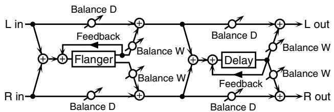
flowchart
graph TD
    L_in["L in"] -->|Balance D| Sum1["+"]
    R_in["R in"] -->|Balance D| Sum2["+"]
    Sum1 --> Feedback["Feedback"]
    Sum2 --> Flanger["Flanger"]
    Flanger --> BalanceW1["Balance W"]
    BalanceW1 --> Sum1
    Sum1 -->|Balance D| L_out["L out"]
    Sum1 -->|Balance W| R_out["R out"]
    Sum2 -->|Balance D| L_out
    Sum2 -->|Balance W| R_out
    Sum2 -->|Balance W| Flanger
    Flanger --> Feedback
    Feedback --> Sum1
    Sum1 --> Delay["Delay"]
    Delay --> Return["+"]
    Return --> L_out
    Return --> R_out
| Parameter | Value | Description |
| Flanger Pre Delay | 0.0–100.0 ms | Adjusts the delay time from when the direct sound begins until the flanger sound is heard. |
| Flanger Rate # | 0.05–10.00 Hz, note | Frequency of modulation |
| Flanger Depth | 0–127 | Depth of modulation |
| Flanger Feedback # | -98– +98 % | Adjusts the proportion of the flanger sound that is fed back into the effect. Negative (-) settings will invert the phase. |
| Flanger Balance # | D100:0W–D0:100W | Volume balance between the direct sound (D) and the flanger sound (W) |
| Delay Time | 0–2600 ms, note | Adjusts the delay time from the direct sound until the delay sound is heard. |
| Delay Feedback # | -98– +98 % | Adjusts the proportion of the delay sound that is fed back into the effect. Negative (-) settings will invert the phase. |
| Delay HF Damp | 200–8000 Hz, BYPASS | Adjusts the frequency above which sound fed back to the effect will be cut. If you do not want to cut the high frequencies, set this parameter to BYPASS. |
| Delay Balance # | D100:0W–D0:100W | Adjusts the volume balance between the sound that is sent through the delay (W) and the sound that is not sent through the delay (D). |
| Level | 0–127 | Output Level |
75: CHORUS → FLANGER
* MFX only
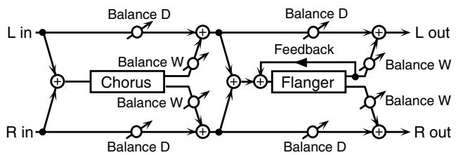
flowchart
graph LR
    L_in --> A["+"]
    R_in --> B["+"]
    A --> C["Balance D"]
    B --> D["Balance D"]
    C --> E["Chorus"]
    D --> F["Feedback"]
    E --> G["Balance W"]
    F --> H["Balance W"]
    G --> I["Flanger"]
    H --> I
    I --> J["Balance D"]
    J --> K["R out"]
    L_out --> L
    L_in --> Lout
    R_in --> R
    L --> Lout
    R --> Lout
    L --> Lout
    L --> Lout
    L --> Lout
    L --> Lout
    L --> Lout
    L --> Lout
    L --> Lout
| Parameter | Value | Description |
| Chorus Pre Delay | 0.0–100.0 ms | Adjusts the delay time from the direct sound until the chorus sound is heard. |
| Chorus Rate # | 0.05–10.00 Hz, note | Modulation frequency of the chorus effect |
| Chorus Depth | 0–127 | Modulation depth of the chorus effect |
| Chorus Balance # | D100:0W–D0:100W | Volume balance between the direct sound (D) and the chorus sound (W) |
| Flanger Pre Delay | 0.0–100.0 ms | Adjusts the delay time from when the direct sound begins until the flanger sound is heard. |
| Flanger Rate # | 0.05–10.00 Hz, note | Modulation frequency of the flanger effect |
| Parameter | Value | Description |
| Flanger Depth | 0–127 | Modulation depth of the flanger effect |
| Flanger Feedback # | -98– +98 % | Adjusts the proportion of the flanger sound that is fed back into the effect. Negative (-) settings will invert the phase. |
| Flanger Balance # | D100:0W–D0:100W | Adjusts the volume balance between the sound that is sent through the flanger (W) and the sound that is not sent through the flanger (D). |
| Level | 0–127 | Output Level |
76: SYMPATHETIC RESONANCE
On an acoustic piano, holding down the damper pedal allows other strings to resonate in sympathy with the notes you play, creating rich and spacious resonances. This effect simulates these sympathetic resonances.
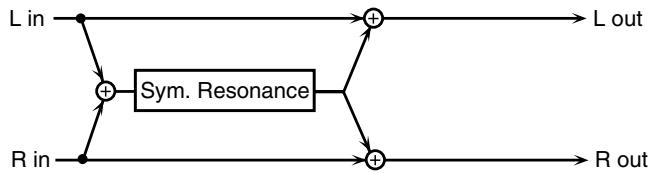
flowchart
graph LR
    L_in --> A["+"]
    R_in --> B["+"]
    A --> C["Sym. Resonance"]
    B --> C
    C --> D["+"]
    E["L out"] --> D
    F["R out"] --> D
| Parameter | Range | Explanation |
| Damper # | 0–127 | Depth to which damper pedal is pressed (controls the sympathetic resonance) |
| Depth # | 0–127 | Depth of the effect |
| Octave | -3– +3 oct | Octave shift amount for the sympathetic resonance |
| Detune | -50– +50 cent | Pitch shift amount for the sympathetic resonance |
| Phase | NORMAL, INVERSE | Phase at which the sympathetic resonance is generated |
| Low Damp Freq | 20–1000 Hz | Frequency at which the low range of the sympathetic resonance is cut |
| Low Damp | 1–100 % | Amount of attenuation by which the low range of the sympathetic resonance is cut (100%: no effect) |
| High Damp Freq | 1000–10000 Hz | Frequency at which the high range of the sympathetic resonance is cut |
| High Damp | 1–100 % | Amount of attenuation by which the high range of the sympathetic resonance is cut (100%: no effect) |
| Time | 10–5000 ms | Time over which the sympathetic resonance will decay (lowering the Octave setting will make this more noticeable) |
| Level | 0–127 | Output Level |
77: REVERB
Adds reverberation to the sound, simulating an acoustic space.
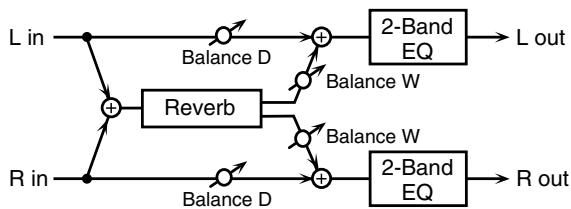
flowchart
graph LR
    L_in --> A["+"]
    R_in --> B["+"]
    A --> C["Balance D"]
    B --> D["Balance D"]
    C --> E["Reverb"]
    D --> F["Reverb"]
    E --> G["+"]
    F --> H["+"]
    G --> I["2-Band EQ"]
    H --> J["2-Band EQ"]
    I --> K["L out"]
    J --> L["R out"]
    style A fill:#f9f,stroke:#333
    style B fill:#f9f,stroke:#333
    style C fill:#ccf,stroke:#333
    style D fill:#ccf,stroke:#333
    style E fill:#cfc,stroke:#333
    style F fill:#cfc,stroke:#333
    style G fill:#cfc,stroke:#333
    style H fill:#cfc,stroke:#333
    style I fill:#fcc,stroke:#333
    style J fill:#fcc,stroke:#333
| Parameter | Value | Description |
| Type | ROOM1, ROOM2, STAGE1, STAGE2, HALL1, HALL2 | Type of reverbROOM1: dense reverb with short decayROOM2: sparse reverb with short decaySTAGE1: reverb with greater late reverberationSTAGE2: reverb with strong early reflectionsHALL1: reverb with clear reverberanceHALL2: reverb with rich reverberance |
| Pre Delay | 0.0–100.0 ms | Adjusts the delay time from the direct sound until the reverb sound is heard. |
| Time # | 0–127 | Time length of reverberation |
| HF Damp | 200–8000 Hz, BYPASS | Adjusts the frequency above which the reverberant sound will be cut.As the frequency is set lower, more of the high frequencies will be cut, resulting in a softer and more muted reverberance. If you do not want to cut the high frequencies, set this parameter to BYPASS. |
| Low Gain | -15– +15 dB | Gain of the low range |
| High Gain | -15– +15 dB | Gain of the high range |
| Balance # | D100:0W–D0:100W | Volume balance between the direct sound (D) and the reverb sound (W) |
| Level | 0–127 | Output Level |
78: GATED REVERB
This is a special type of reverb in which the reverberant sound is cut off before its natural length.
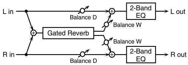
flowchart
graph LR
    L_in --> GatedReverb
    R_in --> GatedReverb
    GatedReverb -->|Balance D| A1["+"]
    GatedReverb -->|Balance W| A2["+"]
    GatedReverb -->|Balance W| A3["+"]
    A1 --> B1["2-Band EQ"]
    A2 --> B2["2-Band EQ"]
    A3 --> B3["2-Band EQ"]
    B1 --> L_out["L out"]
    B2 --> L_out
    B3 --> R_out["R out"]
| Parameter | Value | Description |
| Type | NORMAL, REVERSE, SWEEP1, SWEEP2 | Type of reverbNORMAL: conventional gated reverbREVERSE: backwards re-verbSWEEP1: the reverberant sound moves from right to leftSWEEP2: the reverberant sound moves from left to right |
| Pre Delay | 0.0–100.0 ms | Adjusts the delay time from the direct sound until the re-verb sound is heard. |
| Parameter | Value | Description |
| Gate Time | 5–500 ms | Adjusts the time from when the reverb is heard until it disappears. |
| Low Gain | -15– +15 dB | Gain of the low range |
| High Gain | -15– +15 dB | Gain of the high range |
| Balance # | D100:0W–D0:100W | Volume balance between the direct sound (D) and the re-verb sound (W) |
| Level # | 0–127 | Output Level |
When Using 3D Effects
The following 3D effects utilize RSS (Roland Sound Space) technology to create a spaciousness that cannot be produced by delay, reverb, chorus, etc.
52: 3D DELAY
29: 3D CHORUS
30: 3D FLANGER
31: 3D STEP FLANGER
When using these effects, we recommend that you place your speakers as follows. Also, make sure that the speakers are at a sufficient distance from the walls on either side.
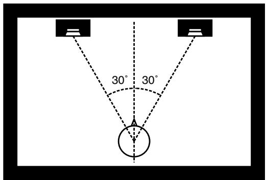
text_image
30° 30°If the left and right speakers are too far apart, or if there is too much reverberation, the full 3D effect may not appear.
Each of these effects has an “Output Mode” parameter. If the sound from the OUTPUT jacks is to be heard through speakers, set this parameter to “SPEAKER.” If the sound is to be heard through headphones, set it to “PHONES.” This will ensure that the optimal 3D effect will be heard. If this parameter is not set correctly, the full 3D effect may not appear.
About the STEP RESET function
06: STEP FILTER
16: STEP RING MODULATOR
19: STEP PAN
20: SLICER
63: STEP PITCH SHIFTER
The above five types contain a sixteen-step sequencer.
For these types, you can use a multi-effect control to reset the sequence to play from the first step.
To do this, set the multi-effect control Destination to "Step Reset."
For example if you are using the modulation lever to control the effect, you would make the following settings.
Source: CC01: MODULATION
Destination: Step Reset
Sens: +63
With these settings, the sequence will play back from the first step whenever you operate the modulation lever.
note:
♂3 (Sixty-fourth-note triplet), ♩ (Sixty-fourth note), ♪ 3 (Thirty-second-note triplet),
(Thirty-second note), ♩₃ (Sixteenth-note triplet), ♩. (Dotted thirty-second note),
♪ (Sixteenth note), ♪₃ (Eighth-note triplet), ♫. (Dotted sixteenth note),
♪ (Eighth note), ♩ (Quarter-note triplet), ♪. (Dotted eighth note),
(Quarter note), (Half-note triplet), (Dotted quarter note), (Half note),
o3 (Whole-note triplet), (Dotted half note), o (Whole note),
Ioll3 (Double-note triplet), (Dotted whole note), IIoll (Double note)
Chorus Parameters
The Fantom-G's Chorus effect unit can also be used as a stereo delay unit.
These settings allow you to select chorus or delay, and the characteristics of the selected effect type.
| Parameter | Value | Description |
| Chorus Type | 00 (OFF), 01 (CHORUS), 02 (DELAY), 03 (GM2 CHORUS) | Selects either Chorus or Delay. 0 (OFF): Neither Chorus or Delay is used. 1 (CHORUS): Chorus is used. 2 (DELAY): Delay is used. 3 (GM2 CHORUS): GM2 Chorus is used. |
| Type: 01 (CHORUS) | ||
| Rate | 0.05–10.00 Hz, note | Frequency of modulation |
| Depth | 0–127 | Depth of modulation |
| Pre Delay | 0.0–100.0 ms | Adjusts the delay time from the direct sound until the chorus sound is heard. |
| Feedback | 0–127 | Adjusts the amount of the chorus sound that is fed back into the effect. |
| Filter Type | OFF, LPF, HPF | Type of filter OFF: no filter is used LPF: cuts the frequency range above the Cutoff Freq HPF: cuts the frequency range below the Cutoff Freq |
| Cutoff Freq | 200–8000 Hz | Basic frequency of the filter |
| Phase | 0–180° | Spatial spread of the sound |
| Type: 02 (DELAY) | ||
| Delay Left | 0–1000 ms, note | Adjusts the delay time from the direct sound until the delay sound is heard. |
| Delay Right | ||
| Delay Center | ||
| Center Feedback | -98–+98 % | Adjusts the proportion of the delay sound that is fed back into the effect. Negative (-) settings will invert the phase. |
| HF Damp | 200–8000 Hz, BYPASS | Adjusts the frequency above which sound fed back to the effect will be cut. If you do not want to cut the high frequencies, set this parameter to BYPASS. |
| Left Level | 0–127 | Volume of each delay sound |
| Right Level | ||
| Center Level | ||
| Type: 03 (GM2 CHORUS) | ||
| Pre-LPF | 0–7 | Cuts the high frequency range of the sound coming into the chorus. Higher values will cut more of the high frequencies. |
| Level | 0–127 | Volume of the chorus sound |
| Feedback | 0–127 | Adjusts the amount of the chorus sound that is fed back into the effect. |
| Delay | 0–127 | Adjusts the delay time from the direct sound until the chorus sound is heard. |
| Rate | 0–127 | Frequency of modulation |
| Depth | 0–127 | Depth of modulation |
| Send Level To Reverb | 0–127 | Adjusts the amount of chorus sound that will be sent to the reverb. |
note:
♪3 (Sixty-fourth-note triplet), ♪ (Sixty-fourth note), ♪3 (Thirty-second-note triplet),
♪ (Thirty-second note), ♪_3 (Sixteenth-note triplet), ♪ . (Dotted thirty-second note),
(Sixteenth note), ♩₃ (Eighth-note triplet), ♩. (Dotted sixteenth note),
♪ (Eighth note), ♩ (Quarter-note triplet), ♪. (Dotted eighth note),
(Quarter note), (Half-note triplet), (Dotted quarter note), (Half note),
o3 (Whole-note triplet), (Dotted half note), o (Whole note),
lloll3 (Double-note triplet), o- (Dotted whole note), loll (Double note)
Reverb Parameters
These settings allow you to select the desired type of reverb, and its characteristics.
| Parameter | Value | Description |
| Reverb Type | 00 (OFF),01 (REVERB),02 (SRV ROOM),03 (SRV HALL),04 (SRV PLATE),05 (GM2 RE-VERB),06 (ROOM),07 (HALL),08 (PLATE),09 (STUDIO),10 (CHURCH) | Type of reverb |
| Type: 01 (REVERB) | ||
| Type | ROOM1,ROOM2,STAGE1,STAGE2,HALL1, HALL2,DELAY,PAN-DELAY | Type of reverb/delayROOM1: short reverb with high densityROOM2: short reverb with low densitySTAGE1: reverb with greater late rever-berationSTAGE2: reverb with strong early reflectionsHALL1: very clear-sounding reverbHALL2: rich reverbDELAY: conventional delay effectPAN-DELAY: delay effect with echoes that pan left and right |
| Time | 0–127 | Time length of reverberation(Type: ROOM1-HALL2)Delay time(Type: DELAY, PAN-DELAY) |
| HF Damp | 200–8000 Hz,BYPASS | Adjusts the frequency above which the high-frequency content of the reverb sound will be cut, or “damped.” If you do not want to cut the high frequencies, set this parameter to BYPASS. |
| Delay Feedback | 0–127 | Adjusts the amount of delay feedback when the Type setting is DELAY or PAN-DELAY. |
| Type: 02 (SRV ROOM)/03 (SRV HALL)/04 (SRV PLATE) | ||
| Pre Delay | 0.0–100.0 ms | Adjusts the delay time from the direct sound until the reverb sound is heard. |
| Time | 0–127 | Time length of reverberation |
| Size | 1–8 | Size of the simulated room or hall |
| High Cut | 160 Hz–12.5 kHz,BYPASS | Adjusts the frequency above which the high-frequency content of the reverb will be reduced. If you do not want to reduce the high frequencies, set this parameter to BYPASS. |
| Density | 0–127 | Density of reverb |
| Diffusion | 0–127 | Adjusts the change in the density of the reverb over time. The higher the value, the more the density increases with time. (The effect of this setting is most pronounced with long reverb times.) |
| LF Damp Freq | 50–4000 Hz | Adjusts the frequency below which the low-frequency content of the reverb sound will be reduced, or “damped.” |
| LF Damp Gain | -36–0 dB | Adjusts the amount of damping applied to the frequency range selected with LF Damp. With a setting of “0,” there will be no reduc-tion of the reverb’s low-frequency content. |
| HF Damp Freq | 4000 Hz–12.5 kHz | Adjusts the frequency above which the high-frequency content of the reverb sound will be reduced, or “damped.” |
| HF Damp Gain | -36–0 dB | Adjusts the amount of damping applied to the frequency range selected with HF Damp. With a setting of “0,” there will be no reduc-tion of the reverb’s high-frequency content. |
| Type: 05 (GM2 REVERB) | ||
| Character | 0–7 | Type of reverb0–5: reverb6, 7: delay |
| Pre-LPF | 0–7 | Cuts the high frequency range of the sound coming into the reverb.Higher values will cut more of the high frequencies. |
| Level | 0–127 | Output level of reverbration |
| Time | 0–127 | Time length of reverberation |
| Delay Feedback | 0–127 | Adjusts the amount of the delay sound that is fed back into the effect when the Reverb Character setting is 6 or 7. |
| Parameter | Value | Description |
| Type: 06 (ROOM)/09 (STUDIO) | ||
| Pre Delay | 0–127 | Adjusts the delay time from the direct sound until the reverb sound is heard. |
| Time | 0.1–3.0 sec | Time length of reverberation |
| Low Damp Freq | 20–1000 Hz | Adjusts the frequency below which the low-frequency content of the reverb sound will be reduced, or “damped.” |
| Low Damp | 1–100 % | Adjusts the amount of damping applied to the frequency range selected with LF Damp. With a setting of “100%,” there will be no reduction of the reverb’s low-frequency content. |
| Hi Damp Freq | 1000–10000 Hz | Adjusts the frequency above which the high-frequency content of the reverb sound will be reduced, or “damped.” |
| High Damp | 1–100 % | Adjusts the amount of damping applied to the frequency range selected with HF Damp. With a setting of “100%,” there will be no reduction of the reverb’s high-frequency content. |
| High Cut | 1000–10000 Hz | Adjusts the frequency above which the high-frequency content of the reverb will be reduced. |
| Type: 07 (HALL)/08 (PLATE)/10 (CHURCH) | ||
| Pre Delay | 0–127 | Adjusts the delay time from the direct sound until the reverb sound is heard. |
| Time | 0.1–6.0 sec | Time length of reverberation |
| Low Damp Freq | 20–1000 Hz | Adjusts the frequency below which the low-frequency content of the reverb sound will be reduced, or “damped.” |
| Low Damp | 1–100 % | Adjusts the amount of damping applied to the frequency range selected with LF Damp. With a setting of “100%,” there will be no reduction ofthe reverb’s low-frequency content. |
| Hi Damp Freq | 1000–10000 Hz | Adjusts the frequency above which the high-frequency content of the reverb sound will be reduced, or “damped.” |
| High Damp | 1–100 % | Adjusts the amount of damping applied to the frequency range selected with HF Damp. With a setting of “100%,” there will be no reduction ofthe reverb’s high-frequency content. |
| High Cut | 1000–10000 Hz | Adjusts the frequency above which the high-frequency content of the reverb will be reduced. |
Input Effect Parameters
Selects the type of effect that will be applied to the external input source.
01: EQUALIZER
Adjusts the tone of the low-frequency and high-frequency ranges.
| Parameter | Range | Explanation |
| Low Freq | 200, 400 Hz | Center frequency of the low-frequency range |
| Low Gain | -15– +15 dB | Amount of low-frequency boost/cut |
| High Freq | 2000, 4000, 8000 Hz | Center frequency of the high-frequency range |
| High Gain | -15– +15 dB | Amount of high-frequency boost/cut |
02: ENHANCER
Modifies the harmonic content of the high-frequency range to add sparkle to the sound.
| Parameter | Range | Explanation |
| Sens | 0–127 | Depth of the enhancer effect |
| Mix | 0–127 | Volume of the harmonics that are generated |
03: COMPRESSOR
Restrains high levels and boosts low levels to make the overall volume more consistent.
| Parameter | Range | Explanation |
| Attack | 0–127 | Time from when the input exceeds the Threshold until the volume begins to be compressed |
| Threshold | 0–127 | Volume level at which compression will begin |
| Post Gain | 0– +18 dB | Level of the output sound |
04: LIMITER
Compresses the sound when it exceeds a specified volume, to keep distortion from occurring.
| Parameter | Range | Explanation |
| Release | 0–127 | Time from when the input falls below the Threshold until compression ceases |
| Threshold | 0–127 | Volume level at which compression will begin |
| Post Gain | 0– +18 dB | Level of the output sound |
05: NOISE SUPPRESSOR
Suppresses noise during periods of silence.
| Parameter | Range | Explanation |
| Threshold | 0–127 | Volume at which noise suppression will begin |
| Release | 0–127 | Time from when noise suppression begins until the volume reaches zero. |
06: CENTER CANCELER
Removes the sounds that are localized at the center of the stereo input. This is a convenient way to eliminate a vocal.
| Parameter | Range | Explanation |
| Ch Balance | -50–+50 | Volume balance of the L (left) and R (right) channels for removing the sound |
| Range Low | 16–15000 Hz | Lower frequency limit of the band to be removed |
| Range High | 16–15000 Hz1 | Upper frequency limit of the band to be removed |
05: Pads (Using the Pads)
This chapter explains how to use the pads.
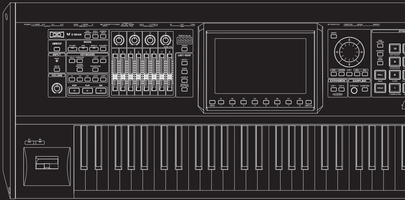
text_image
PROKES L/L MISO 2/R 3/L 4/R LEVEL L-MISO 5 MECUTAIN LEVEL 6 M.1.2 GURAN HOLD I-CTR=2 IN OUT TURU OUTPUT LINE INPUT INPUT PRANTOR PAC FOUR PIEDAL IN V8 D BEAM SOLDER SOULD ASSEMBLY MODE STUDIO LIVE SINGLE FAUCERS INPUT PEAK HOLD APPROXED 3OCT 4OCT CHORD MENTION TRANSPONSE VOLUME STOP PLAY REC LIST/EDIT PATCH DOYS SAMPLE CAPSIC (RDT/RDS) EXPANSION SAMPLING EXP 1 EXP 2 SKEEBACK SAMPLING HOLD 1 SAMPLE PAD 2 S1 SB WIFE TAB/BOX 13 FAD MODE 9 ROLL 5 B/SCHOOL 6/WR DINJ COMPUTER MOUSE MEMORY IN-COMP-OUT COMPUTER MOUSE MEMORY F1 F2 F3 F4 F5 F6 F7 F8 MENU 1 2 3 4 5 6 7 8 DISPLAYCommon Operations for Pads
Switching the Pad Mode (PAD MODE)
You can strike the Fantom-G's pads to play samples, rhythms, or phrases, or you can use the pads as sixteen switches to turn various parameters on/off. The pads can operate in one of sixteen modes. Press [PAD MODE] to switch the pad mode.
1. Press [PAD MODE].
The pad mode window will appear in the screen.
[PAD MODE] will blink, and the currently selected pad mode (pad [1]–[16]) will blink.
MEMO
If you decide not to switch the pad mode, press [PAD
MODE] once again. [PAD MODE] will go dark, and you'll return to the previous state.
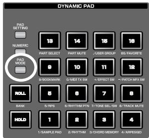
text_image
DYNAMIC PAD PAD SETTING NUMERIC PAD MODE 18 14 16 18 PART SELECT PART MUTE /USER GROUP BS/FAVCHTE 9 10 11 12 S/BOOKMARK O/MDT TX SW +EFFECT SW -7/PATCH MFX SW ROLL 5 6 7 8 BANK 5/TPS 6/RHYTHM PTN 7/TONE SEL/SW 8/TRACK MUTE HOLD 1 2 3 4 1/SAMPLE PAD 2/RHYTHM 3/CHORD MEMORY 4/ARPEGADO2. Press a pad [1]–[16].
The pad mode will be switched. For details about operation in each pad mode, refer to the table below and the corresponding reference pages.
| Pad number | Pad mode | Explanation | Page |
| 1 | SAMPLE PAD | The pads play a sample set | p. 191 |
| 2 | RHYTHM | The pads play a rhythm set | p. 192 |
| 3 | CHORD MEMORY | The pads switch chord form for the Chord Memory function (p. 81) | p. 193 |
| 4 | ARPEGGIO | The pads switch styles for the Arpeggio function (p. 78) | p. 193 |
| 5 | RPS | The pads play phrases | p. 194 |
| 6 | RHYTHM PTN | The pads play rhythm patterns | p. 196 |
| 7 | TONE SEL/SW | The pads act as tone select and on/off switches | p. 197 |
| 8 | TRACK MUTE | The pads switch muting on/off for sequencer tracks | p. 197 |
| 9 | BOOKMARK | The pads recall frequency-used screens that you’ve registered | p. 198 |
| 10 | MIDI TX SW | The pads act as on/off switches for external MIDI transmit channels (1-16) | p. 198 |
| 11 | EFFECT SW | The pads switch the effects (other than the patch multi-effects) | p. 199 |
| 12 | PATCH MFX SW | The pads switch the patch multi-effect for each part | p. 199 |
| 13 | PART SELECT | The pads select parts (1-16) and banks (INT/EXP1/EXP2/EXT) | p. 200 |
| 14 | PART MUTE | The pads switch muting on/off for parts (1-16) and banks (INT/EXP1/EXP2) | p. 200 |
| 15 | USER GROUP | The pads register/recall patches, live sets, or studio sets from the user group | p. 201 |
| 16 | FAVORITE | The pads register/recall Favor-ite settings | p. 202 |
| Pad number | Pad mode | Explanation | Page |
| 1 | SAMPLE PAD | The pads play a sample set | p. 191 |
| 2 | RHYTHM | The pads play a rhythm set | p. 192 |
| 3 | CHORD MEMORY | The pads switch chord form for the Chord Memory function (p. 81) | p. 193 |
| 4 | ARPEGGIO | The pads switch styles for the Arpeggio function (p. 78) | p. 193 |
| 5 | RPS | The pads play phrases | p. 194 |
| 6 | RHYTHM PTN | The pads play rhythm patterns | p. 196 |
| 7 | TONE SEL/SW | The pads act as tone select and on/off switches | p. 197 |
| 8 | TRACK MUTE | The pads switch muting on/off for sequencer tracks | p. 197 |
| 9 | BOOKMARK | The pads recall frequency-used screens that you’ve registered | p. 198 |
| 10 | MIDI TX SW | The pads act as on/off switches for external MIDI transmit channels (1-16) | p. 198 |
| 11 | EFFECT SW | The pads switch the effects (other than the patch multi-effects) | p. 199 |
| 12 | PATCH MFX SW | The pads switch the patch multi-effect for each part | p. 199 |
| 13 | PART SELECT | The pads select parts (1-16) and banks (INT/EXP1/EXP2/EXT) | p. 200 |
| 14 | PART MUTE | The pads switch muting on/off for parts (1-16) and banks (INT/EXP1/EXP2) | p. 200 |
| 15 | USER GROUP | The pads register/recall patches, live sets, or studio sets from the user group | p. 201 |
| 16 | FAVORITE | The pads register/recall Favor-ite settings | p. 202 |
Using the Pads as Numeric Keys (NUMERIC)
If you press the pad [NUMERIC] button to make it light, the pads will act as numeric keys.
→ “Using the pad for numeric input” (p. 41)
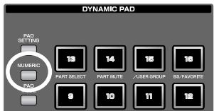
text_image
DYNAMIC PAD PAD SETTING NUMERIC PAD 13 14 15 16 PART SELECT PART MUTE USER GROUP BS-FONCRTE 8 10 11 12Using the Hold Function to Sustain the Sounds (HOLD)
By using the Hold function, you can make the sound continue even after you take your finger off the pad. This is convenient when you want a sound to continue, such as a phrase that you want to loop (play repeatedly).
MEMO
The Hold function is available only if the pad mode is 1 SAMPLE PAD or 2 RHYTHM.
Sustaining a sound while you play other sounds
1. While holding down a pad, press [HOLD].
[HOLD] and the pad will blink.
That pad will be held, and will continue sounding even after you release your finger from it. If you press another pad in this state, it will sound only as long as you continue holding it.
![ROLAND FANTOM G8 - While holding down a pad, press [HOLD]. - 1](/content/2025/01/130804/images/fb16034c1d939d4054e9c18f53272f34c3032d9a53784d4d22a98e741a35a219.jpg)
text_image
DYNAMIC PAD PAD SETTING NUMERIC PAD MODE ROLL RANK HPLD 13 14 15 16 PART SELECT PART MUTE USER GROUP BS/FAVORATS 9 10 11 8/BOOKMARK O/MET TX SW F/EFFECT SW &/PATCH MFX S 5 6 7 8 5/RPS 6/RHYTHM PTN 7/TONE SEL/SW 8/TRACK MUTI 1 2 3 4 1/7/10/10/10/10/10/10/10/10/10/10/10/10/10/10/10/10/10/10/10/10/10/10/10/10/10/10/10/10/10/10/10/10/10/102. The pad that was being held will stop sounding when you press the blinking pad or [HOLD] once again.
Sustaining multiple sounds
1. Press [HOLD] to make the pad light.
2. Press a pad.
The pad will blink, and will continue sounding. If you press other pads in this state, they will also continue sounding.
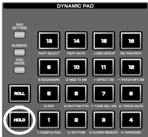
text_image
DYNAMIC PAD PAD SETTING NUMERC PAD MODE PART SELECT 8/BOOKMARK ROLL 5/NPS HOLD 1/SAMPLE PAD 14 PART MUTE 10 0/MIDI TX SW 8 6/RYTHM PTN 2/RYTHM 13 USER GROUP 11 +/-EFFECT SW 7/PATH MFX SW 8 7/TONE SEL/SW 3/CHORD MEMORY 4/ARPEGIDG3. The sound will stop when you once again press a blinking pad. If you press [HOLD], all pads will stop sounding.
NOTE
The Hold function won't work in the following situations.
- For a rhythm set in which “Tone Env Mode” (p. 108) is set to “NO-SUS”
- For a sample set in which “One Shot Mode” (p. 118) is turned on
- For a sample set in which “Trigger Mode” (p. 129) is set to “DRUM”
Using the Roll Function (ROLL)
The Roll function lets you play the sound repeatedly (as if you are playing a drum roll) as long as you continue holding down the pad.
MEMO
The Roll function is available only if the pad mode is 1 SAMPLE PAD or 2 RHYTHM.
1. Hold down [ROLL] and press a pad (1–16).
* If you press only [ROLL], the Roll function will be enabled for all sixteen pads.
In this state, the sound will continue repeating as long as you hold down a pad.
2. When you release the pad, it will stop sounding.
* You can't use this to switch images with the V-Link function (p. 305).
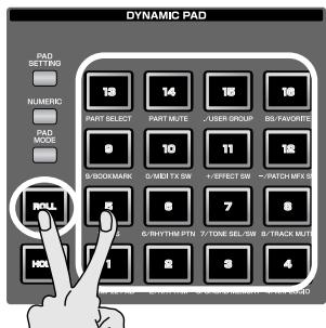
text_image
DYNAMIC PAD PAD SETTING 13 14 15 16 NUMERIC PART SELECT PART MUTE USER GROUP ISS-FAVOREDS 0 10 11 12 PAD MODE B-BOOKMARK 0-MET TX SW 7-EFFECT SW 7-PATCH MFG SW ROLL 6-RHYTH PTH 7-TONE SEL/SW 8-TRACK MUTS 1 2 3 4 HOLDSettings for the Roll function
Press [PAD SETTING]– [F1 (System)] to access the System Setup screen, and use the Pad Roll Resolution field to specify the speed at which repeated strikes occur when using the Roll function.
cf.
- “Editing settings common to all pads (System settings)” (p. 190)
- “Pad Roll Resolution” (p. 292)
Switching Banks (BANK)
You can use the pad [ROLL] (BANK) button to switch banks in the following pad modes.
| Pad number | Pad mode | Number of banks |
| 9 | BOOKMARK | 8 |
| 13 | PART SELECT | 4 (INT/EXP1/EXP2/EXT) |
| 14 | PART MUTE | 3 (INT/EXP1/EXP2) |
| 15 | USER GROUP | 4 |
| 16 | FAVORITE | 16 |
1. Press [ROLL] (BANK).
[ROLL] (BANK) will blink, and pads that correspond to selectable banks will blink. The pad corresponding to the currently selected bank will be lit.
2. Press the bank (a blinking number pad) for the desired bank.
The selected pad will light.
3. Press [ROLL] (BANK) once again.
[ROLL] (BANK) will go dark, and the pads will return to their normal indication.
![ROLAND FANTOM G8 - Press [ROLL] (BANK) once again. - 1](/content/2025/01/130804/images/bcfa638a1b853d21f8970c4a96d03f0d354f47b7ee901c4545f044e519afbaaf.jpg)
text_image
DYNAMIC PAD PAD SETTING 13 14 15 16 NUMERIC PART SELECT PART MUTE USER GROUP B/S-FAVORTE PAD MODE 9 10 11 16 B/BOOKMARK MIDI TX SW + EFFECT SW ~/PATCH MFX SW ROLL 8 8 7 8 5/IPS 6/ RHYTHM PTR 7/ TONE SEL/SW B/TRACK MUTE HOLD 1 2 3 4 1/SAMPLE PAD 2/ RHYTHM 3/ CHORD MEMORY 4/ ARFCD/30Editing the Pad Settings (PAD SETTING)
Press [PAD SETTING] to access the pad settings/information screen.
1. Press [PAD SETTING].
The Pad Setting screen will appear. The content shown in the screen will depend on the pad mode.
2. Use [CURSOR] to move the cursor to a parameter.
3. Turn the VALUE dial or use [INC] [DEC] to edit the pad settings.
4. To save the settings, press [F7 Write].
MEMO
The location in which the settings are saved will depend on the sound generator mode, the pad mode, and the settings of “Pad Assign Source” (p. 292).
5. Press [F8 Exit] to return to the previous screen.
F-key operations in the Pad Setting screen
| F-key | Explanation | Display mode |
| F1System | Pad settings for System (p. 190) | All modes* Except for 15 USER GROUP and 16 FAVORITE |
| F2Pad Exchg | Pad Exchange function (p. 190) | 2 RHYTHM,3 CHORD MEMORY,4 ARPEGGIO,5 RPS,6 RHYTHM PTN,9 BOOKMARK only |
| F3Quick Setup | Quick Setup function (p. 192, p. 195, p. 197) | 2 RHYTHM,5 RPS,6 RHYTHM PTN only |
| F4PlayMode All | Applies the Play Mode to all (p. 195) | 5 RPS only |
| F6Rhythm Ptn / RPS | Switches you between the RHYTHM PTN and RPS modes. | 5 RPS,6 RHYTHM PTN only |
| F7Write | Saves the settings of the Pad Setting screen | 1 SAMPLE PAD,2 RHYTHM,3 CHORD MEMORY,4 ARPEGGIO,5 RPS,6 RHYTHM PTN only |
| F8Exit | Exits the Pad Setting screen | All modes* Except for 15 USER GROUP and 16 FAVORITE |
![ROLAND FANTOM G8 - Press [F8 Exit] to return to the previous screen. - 1](/content/2025/01/130804/images/54098f169d4739060b2ac3d3d4ae8aa6221261af6d583e19f125127fbb63467a.jpg)
text_image
DYNAMIC PAD PAD SETTING NOMING 13 14 15 16 PART SELECT PART MUTE USER GROUP B5/FAVORATE 0 10 11 12 9/BOOKMARK 0/MET TX SW +EFFECT SW ~/PATCH MFX SW ROLL 8 8 7 8 5/IPS 6/RHYTHM PTR 7/TONE SEL/SW 8/TRACK MUTE HOLD 1 2 3 4 1/SAMPLE PAD 2/RHYTHM 3/WORD MEMORY 4/ARPEGGOEditing settings common to all pads (System settings)
In the Pad Setting screen, press [F1 System] to access the system setting screen where you can edit settings that are common to all pads. Here you can edit the following parameters.
- "Pad Assign Source" (p. 292)
- “Pad Velocity” (p. 292)
- “Pad Sens (Pad Sensitivity)” (p. 292)
- “Pad Aftertouch Sens (Pad Aftertouch Sensitivity)” (p. 292)
- “Pad Roll Resolution” (p. 292)
- “Pad Mode” (p. 292)
1. Press [PAD SETTING].
The Pad Setting screen will appear.
2. Press [F1 System].
The pad-related items of the System Setup screen will appear.
cf.
For details on each parameter, refer to "Dynamic Pad" (p. 292).
3. To save the settings, press [F7 Sys Write].
4. Press [F8 Exit] to return to the Pad Setting screen.
Exchanging Pads (Pad Exchange)
Here's how to exchange two selected pads.
MEMO
This function is available only if the pad mode is 2 RHYTHM, 3 CHORD MEMORY, 4 ARPEGGIO, 5 RPS, 6 RHYTHM PTN, or 9 BOOKMARK.
1. Press [PAD SETTING].
![ROLAND FANTOM G8 - Press [PAD SETTING]. - 1](/content/2025/01/130804/images/2a92f52b4b1d471793428f7c8736211e93f9e8ca3bfcf007529c8c589cd55231.jpg)
text_image
DYNAMIC PAD PAD SETTING NOMING 13 14 15 16 PART SELECT PART MUTE USER GROUP BS-FAVORATE 0 10 11 12 9/1000MARK 0/MET TX SW 4/EFFECT SW 7/PATCH MFX SW ROLL 5 6 7 8 BANK 5/TIPS 6/RHYTHM PTN 7/TONE SEL SW 8/TRACK MUTE HOLD 1 2 3 4 1/SAMPLE PAD 2/RHYTHM 3/CHORD MEMORY 4/APPLICADO2. Press [F2 (Pad Exchg)].
3. Select the two pads you want to exchange.
Use the VALUE dial or [INC] [DEC], or press the pads directly.
4. Press [F8 (Execute)] to execute the exchange.
1 SAMPLE PAD (Using the Pads to Play Samples)
This pad mode allows you to play samples by striking the pads. You can assign a sample to each of the sixteen pads. (The sixteen samples assigned to the pads are collectively called a "sample set.")
- Press [PAD MODE], and then press pad [1] (SAMPLE PAD).
- Press the pads [1]–[16] to play the assigned samples.
- Pads that can play samples will be lit. Currently-playing pads will blink.
You can press [HOLD] to sustain the sound p. 188
You can press [ROLL] to play a roll p. 189
About Samples
You can add samples in either of the following ways.
Sampling (p. 258)
You can use the Sampling function to record audio. The recorded samples will be added to the sample list.
Import from your computer (p. 287)
You can import WAV or AIFF files from your computer. The imported WAV or AIFF files will be added to the sample list as samples.
Editing the Pad Settings
You can press [PAD SETTING] to edit the following settings.
For details on editing and saving, refer to “Editing the Pad Settings (PAD SETTING)” (p. 190).
Number/Name (Sample set number)
Selects the sample set played by the pads.
Value: 001–128
If you want to create a new sample set or perform more detailed editing, refer to “Creating a Sample Set” (p. 126).
Sample Number
Selects the sample. The screen will show the sample name together with the sample number.
Value: OFF, 0001–2000
Level (Sample tone level)
Sets the volume of the sample. You'll use this mainly to adjust the volume balance between samples.
Value: 0–127
Pan (Sample tone pan)
Sets the panning of the sample tone. "L64" is far left, "0" is center, and "63R" is far right.
Value: L64-0-63R
Direction
Specifies the playback direction of the sample.
Value
FWD: Play forward.
REV: Play in reverse.
Trigger Mode
Specifies how the sample will play when you press a pad (or a key).
Value
GATE: The sample will stop playing when you release the pad (or key).
DRUM: The sample will continue playing even if you release the pad (or key).
NOTE
The sample will begin playing when you press the pad, and will stop automatically when the end of the sample is reached. If you select the DRUM setting, the Loop setting is ignored; the sample will play only once. Note that if you select DRUM, you will not be able to interrupt the sound, so use this setting with caution if the sample is extremely long.
Mute Group
In an acoustic drum set, it is impossible for the open hi-hat and closed hi-hat sounds to occur simultaneously. You can use the Mute Group setting to simulate such restrictions.
Mute Group is a function that prevents sample tones belonging to the same mute group from sounding simultaneously. There are sixteen mute groups. Choose the “OFF” setting for sample tones that you don’t want to associate with any mute group.
Value: OFF, 1–16
Pad Velocity
Specifies the strength of the sound produced when you strike the pad. If this is set to “SYSTEM,” the System setting of “Pad Velocity” (p. 292) will be used. If you set this to a value of “1–127,” that velocity value will be used to play the sound generator.
Value: SYSTEM, 1–127

You can save the pad settings by pressing [F7 (Write)].
2 RHYTHM (Using the Pads to Play a Rhythm Set)
This pad mode allows you to play a rhythm set by striking the pads. You can use the sixteen pads to play rhythm tones. (A set of rhythm tones is called a “rhythm set.”)
- Press [PAD MODE], and then press pad [2] (RHYTHM).
- Press the pads [1]–[16] to play rhythm tones.
- Pads that can play rhythm tones will light.
You can press [HOLD] to sustain the sound p. 188

You can press [ROLL] to play a roll → p. 189
Editing the Pad Settings
You can press [PAD SETTING] to edit the following settings.
For details on editing and saving, refer to “Editing the Pad Settings (PAD SETTING)” (p. 190).
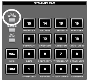
text_image
DYNAMIC PAD PAD SETTING NUMERIC 13 14 15 16 PART SELECT PART MUTE ;USER GROUP BS-FAVORITE 0 10 11 12 9:BOOKMARK 0/MBT TX SW +;EFFECT SW +;PATCH MEX SW ROLL 5 6 7 8 BANK 5/TPS 6/RHYTHM PTN 7/TONE SEL/SW 8/TRACK MUTE HOLD 1 2 3 4 1/SAMPLE PAD 2/RHYTHM 3/CHORD MEMORY 4/ARPLUGOIn the Pad Setting screen, you can press [F2 (Pad Exchg)] to exchange two pads (Pad Exchange, p. 190).
Bank (Rhythm set bank)
Selects the bank of the rhythm set that will be played by the pads.
Value: USER, PRST, GM
Number / Name
Selects the rhythm set that will be played by the pads.
Value:
•Bank USER: 001-064
• Bank PRST: 001-064
• Bank GM: 001-009
If you want to create a new sample set or perform more detailed editing, refer to “Creating a Rhythm Set” (p. 112).
Pad Note Number
Specifies the note number transmitted by each pad (1–16). The rhythm tone name will be displayed together with the note number.
Value: 0 (C-1)-127 (G9)
Pad Velocity
Specifies the strength of the sound produced when you strike the pad. If this is set to “SYSTEM,” the System setting of “Pad Velocity” (p. 292) will be used. If you set this to a value of “1–127,” that velocity value will be used to play the sound generator.
Value: SYSTEM, 1–127
Quick Setup
When the pad mode is “2 RHYTHM,” you can use this function to make basic settings. For efficient work-flow, choose the quick setup that is closest to your needs, and then make detailed settings for each pad as desired.
- In the Pad Setting screen, press [F3 (Quick Setup)].
The Quick Setup window will appear.
* This operation is not possible unless the pad mode is "2 RHYTHM."
- Move the cursor and make the desired settings.
- Template Set
Value
Note: The sixteen consecutive notes starting with the note number you specify as the base note will be automatically assigned to the pads.
Rhythm: The note numbers will be arranged optimally for playing a rhythm set.
Multi Velo: Multi Velocity is a special setting that assigns all sixteen pads to the same number, with only the velocities differing between the pads. This is a good choice when you need precise control of the velocity for your performance.
- Base Note
Set this parameter if you've selected Note or Multi Velo as the Template Set.
If you've selected Note, the Base Note specifies the starting (lowest) note number.
If you've selected Multi Vel, the Base Note specifies the note number used by all of the pads.
Value: 0 (C-1)-127 (G9)
- Press [F8 (Execute)].

You can save the pad settings by pressing [F7 (Write)].
3 CHORD MEMORY (Using the Pads to Switch Chord Forms)
This pad mode allows you to use the pads to switch chord forms for the Chord Memory function (p. 81).
- Press [PAD MODE], and then press pad [3] (CHORD MEMORY).
- Press pads [1]–[16] to switch between different chord forms for the Chord Memory function (p. 81).
- Pads that can be selected will light.
Editing the Pad Settings
You can press [PAD SETTING] to edit the following settings.
For details on editing and saving, refer to “Editing the Pad Settings (PAD SETTING)” (p. 190).
In the Pad Setting screen,
you can press [F2 (Pad Exchg)] to exchange two pads (Pad Exchange, p. 190).
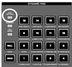
text_image
DYNAMIC PAD PAD SETTING 13 14 15 16 NUMERIC PART SELECT PART MUTE USER GROUP DS-FAVORTE PAD MODE 9 10 11 12 9/BOOKMARK 0/MBI TX SW ~EFFECT SW ~PATCH MFX SW ROLL 5 6 7 8 BANK 5/TPS 6/RYRTH PTN 7/TONE SEL/SW 8/TRACK MUTE HOLD 1 2 3 4 1/SAMPLE PAD 2/RYRTH 3/CHORD MEMORY 4/ARPEGGNumber / Name (Chord memory set number)
Selects the chord memory set that will be played by the pads.
Value: 001–128
For details on Chord Memory, refer to “Using the Chord Memory Function (Chord Memory)” (p. 81).
Chord Form
Selects the chord form number that will be played by each pad (1–16).
Value: 001–128

You can save the pad settings by pressing [F7 (Write)].
4 ARPEGGIO (Using the Pads to Switch Arpeggio Styles)
This pad mode allows you to use the pads to switch styles for the Arpeggio function (p. 78).
- Press [PAD MODE], and then press pad [4] (ARPEGGIO).
- Use the Arpeggio function as described in "Playing Arpeggios" (p. 78).
- Press pads [1]–[16] to switch between different styles for the Arpeggio function.
- Pads that can be selected will light.
Editing the Pad Settings
You can press [PAD SETTING] to edit the following settings.
For details on editing and saving, refer to “Editing the Pad Settings (PAD SETTING)” (p. 190).
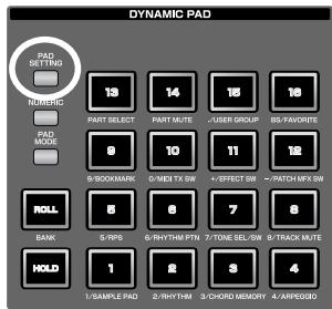
text_image
DYNAMIC PAD PAD SETTING Numeric 19 14 15 16 PART SELECT PART MUTE USER GROUP RS-FAVORATE PAD MODE 9 10 11 12 B/BOOKMARK C/MET TX SW C/EFFECT SW /-PATCH MFX SW ROLL 8 6 7 8 BANK 5/RPS 6/RYTHM PTN 7/TONE SEL/SW 8/TRACK MUTE HOLD 1 2 3 4 1/SAMPLE PAD 2/RYTHM 3/CHORD MEMORY 4/ARPEGID
In the Pad Setting screen, you can press [F2 (Pad Exchg)] to exchange two pads (Pad Exchange, p. 190).
Number / Name (Arpeggio set number)
Selects the arpeggio set.
Value: 001–128
For details on arpeggios, refer to “Playing Arpeggios” (p. 78).
Arpeggio Number
Specifies the arpeggio number selected by each pad (1–16).
Value: 001–128

You can save the pad settings by pressing [F7 (Write)].
5 RPS (Using the Pads to Play Phrases)
This pad mode allows you to use the pads to trigger phrases generated by the RPS (Realtime Phrase Sequence) function.
For example, complex phrases that would be difficult to play manually in a live performance can be assigned to the pads, and then triggered by a single finger at the appropriate moment.
You can also create phrases for individual instruments such as drums, bass, or keyboard, and combine these to create a new song. In addition, you can record this performance, allowing you to use this function in a way similar to phrase sampling.
- Press [PAD MODE], and then press pad [5] (RPS).
- Press the pads [1]–[16] to trigger the phrase assigned to each pad.
- Pads that can play phrases will light. Currently-playing pads will blink.
TIP
You must play back the song if you want to play phrases in synchronization with the song, or if you want to play multiple phrases in synchronization.
- If the song is not playing, the phrase will begin playing as soon as you press the pad, regardless of how the Trigger Quantize parameter is set.
- Phrases will play in synchronization with the song's time signature (beat track). This means that if no performance data has been recorded, the song will not play, and therefore the phrases cannot play back in synchronization. In this case, you'll have to insert several empty measures into the phrase track, and then play it as a loop.
Recording a phrase
Before you use the RPS function, you'll need to record some phrases.
For details on the recording procedure, refer to “Recording into a Phrase” (p. 220).
NOTE
If large amounts of MIDI messages were recorded, playing back a phrase via RPS may cause notes to be delayed.
Specifying the Tempo for Phrase Playback
The phrase playback tempo will be the same as the song playback tempo.
- Press [TEMPO].
- The Tempo window will appear, indicating the current tempo.
- Turn the VALUE dial or use [INC] [DEC] to specify the tempo value (5.00–300.00). If you hold down [SHIFT] and turn the VALUE dial you'll be able to adjust the value below the decimal point. You can also specify the tempo by repeatedly pressing [F6 (Tap Tempo)] at the desired tempo (Tap Tempo function).
MEMO
If you press [F7 (Click)] to turn it on, the click will sound.
- When you've finished making settings, press [F8 (Close)].
Editing the Pad Settings
You can press [PAD SETTING] to edit the following settings.
cf.
For details on editing and saving, refer to “Editing the Pad Settings (PAD SETTING)” (p. 190).
cf.
In the Pad Setting screen, you can press [F2 (Pad Exchg)] to exchange two pads (Pad Exchange, p. 190).
MEMO
Pressing [F6 (Rhythm Ptn)] switches you to the RHYTHM PTN mode.
RPS Set Number
Selects the RPS set.
Value: 01–64
MEMO
RPS Set Numbers are stored on an individual Live/Studio Set basis. Using “RPS Set Assign Source” (p. 292), you can choose to have the RPS Set Number follow the setting of each Live/Studio Set (TEMP), or follow the Fantom-G’s global settings (SYS).
Phrase Number
Selects the phrase that is assigned to each pad 1–16. The name of the selected phrase is shown along with the phrase number.
Choose "OFF" for keys or pads to which you don't want to assign a phrase. If you assign "STOP" to a pad, that pad will act as the "stop trigger" that stops the currently-playing phrases.
Value: STOP, OFF, 0001–2000
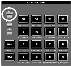
text_image
DYNAMIC PAD PAD SETTING PAD NIMERIC 13 14 15 16 PART SELECT PART MUTE USER GROUP BS-FAVORITE PAD MODE 9 10 11 12 B/BOOKMARK MIDI TX SW EFFECT SW 7/ATCH MFX SW ROLL 8 8 7 8 BANK 5/NPS 6/RHYTHM PTN 7/TONE SEL/SW 8/TRACK MUTE HOLD 1 2 3 4 1/SAMPLE PAD 2/RHYTHM 3/CHORD MEMORY 4/ARPEGGPlay Mode
Specifies how the phrase will be played.
Value
LOOP1: The phrase will play repeatedly while you hold down the pad.
LOOP2: The phrase will play repeatedly. To stop playback, press the stop trigger pad, or press the same pad once again.
ONCE: The phrase will play only once.
Mute Group
This function prevents phrases of the same mute group from playing simultaneously. For example in an actual performance, a fill-in will not be played at the same time as a bridge. To simulate this type of situation, assign the fill-in and bridge to the same mute group number. You can specify 31 different mute groups. If you don't want to assign a mute group, choose the "OFF" setting.
Value: OFF, 1–31
Note Number
If the “Keyboard Mode” (p. 143) is set to RPS you’ll be able to specify the keys that will play RPS Sets.
Value: OFF, 21 (A0)–108 (C8)
MEMO
Move the cursor to the "Note Number" field and press one of the Fantom-G's keys to specify the key that will play the RPS.
Trigger Quantize
Specifies how the phrase will begin playing when you press a pad to trigger it while the song is playing or being recorded.
Value
REAL: The phrase will play immediately when you press the trigger pad.
BEAT: If you press the trigger pad while the song is playing or recording, the phrase will begin playing at the beginning of the next beat.
MEASURE: If you press the trigger pad while the song is playing or recording, the phrase will begin playing at the beginning of the next measure.
MEMO
The Trigger Quantize parameter is a setting maintained within each song.
Velocity Sens (Velocity sensitivity)
Turn this “OFF” if you want the phrase to play with the velocities at which it was recorded.
If you want the velocity of the phrase to vary according to how strongly you pressed the pad, choose "LOW," "MID," or "HIGH."
Value: OFF, LOW, MID, HIGH
MEMO
You can save the pad settings by pressing [F7 (Write)].
Quick Setup
In the Pad Setting screen you can press [F3 (Quick Setup)] to specify the note numbers for sixteen RPS together. For the procedure, refer to “Quick Setup” (p. 192). The parameters will be as follows.
- Template Set
Starting at the base note, the sixteen notes will be assigned to the following keys.
Value
All: White and black keys
White Keys: White keys
Black Keys: Black keys
- Base Note
Specify the lowest note. When the cursor is located at Base Note, you can specify this by pressing a key.
Applying the Play Mode to all (Play Mode All)
In the Pad Setting screen, when the cursor is at the Play Mode field, pressing [F4 (PlayMode All)] will change all sixteen RPS to the Play Mode value of the current cursor location.
6 RHYTHM PTN (Using the Pads to Play Rhythm Patterns)
This pad mode allows you to use the pads to play phrases (Phrase0001–Phrase2000) generated by the Rhythm Pattern function. With the factory settings, sixteen phrases (rhythm patterns) are assigned to the pads. You can create your own rhythm patterns and assign them to the pads, and use the pads as a rhythm machine. A set of these sixteen phrases is called a “rhythm pattern set.”
- Press [PAD MODE], and then press pad [6] (RHYTHM PTN).
- Press the pads [1]–[16] to start the rhythm patterns assigned to each pad.
- Pads that can play rhythm patterns will light. The currently-playing pad will blink.
• To stop playback, press the blinking pad.
Specifying the Tempo for Rhythm Pattern Playback
The rhythm pattern playback tempo will be the same as the song playback tempo.
- Press [TEMPO].
- The Tempo window will appear, indicating the current tempo.
- Turn the VALUE dial or use [INC] [DEC] to specify the tempo value (5.00–300.00). If you hold down [SHIFT] and turn the VALUE dial you'll be able to adjust the value below the decimal point. You can also specify the tempo by repeatedly pressing [F6 (Tap Tempo)] at the desired tempo (Tap Tempo function).
MEMO
If you press [F7 (Click)] to turn it on, the click will sound.
- When you've finished making settings, press [F8 (Close)].
Editing the Pad Settings
You can press [PAD SETTING] to edit the following settings.
cf.
For details on editing and saving, refer to “Editing the Pad Settings (PAD SETTING)” (p. 190).
cf.
In the Pad Setting screen, you can press [F2 (Pad Exchg)] to exchange two pads (Pad Exchange, p. 190).
MEMO
Pressing [F6 (RPS)] switches you to the RPS mode.
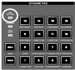
text_image
DYNAMIC PAD PAD SETTING Numeric 13 14 15 16 PART SELECT PART MUTE USER GROUP BS FAVORITE 8 10 11 12 B:9000MARK O:MEL TX SW EFFECT SW /ATCH MFX SW ROLL 5 6 7 8 BANK 5/PPS 6/RHYTH PTN TONE SEL/SW 6/TRACK MUTE HOLD 1 2 3 4 1/SAMPLE PAD 2/RHYTH 3/CHORD MEMORY 4/ARPEGGORhythm Pattern Set Number
Selects the rhythm pattern set that the pads will play.
Value: 01–64
MEMO
Rhythm Pattern Set Numbers are stored on an individual Live/Studio Set basis. Using “Rhythm Pattern Set Assign Source” (p. 292), you can choose to have the Rhythm Pattern Set Number follow the setting of each Live/Studio Set (TEMP), or follow the Fantom-G’s global settings (SYS).
Rhythm Pattern
Specifies the phrase that is assigned to each pad 1–16.
Value: OFF, 0001–2000
Note Number
If the “Keyboard Mode” (p. 143) is set to RHYTHM-PTN, you’ll be able to specify the keys that will play Rhythm Pattern Sets.
Value: OFF, 21 (A0)–108 (C8)
MEMO
Move the cursor to the "Note Number" field and press one of the Fantom-G's keys to specify the key that will play the Rhythm Pattern.
Trigger Quantize
Specifies how the phrase will begin playing when you press a pad to trigger it while the song is playing or being recorded.
Value
REAL: The phrase will play immediately when you press the trigger pad.
BEAT: If you press the trigger pad while the song is playing or recording, the phrase will begin playing at the beginning of the next beat.
MEASURE: If you press the trigger pad while the song is playing or recording, the phrase will begin playing at the beginning of the next measure.
MEMO
The Trigger Quantize parameter is a setting maintained within each song.
Velocity Sens (Velocity sensitivity)
Turn this “OFF” if you want the phrase to play with the velocities at which it was recorded.
If you want the velocity of the phrase to vary according to how strongly you pressed the pad, choose "LOW," "MID," or "HIGH."
Value: OFF, LOW, MID, HIGH
MEMO
You can save the pad settings by pressing [F7 (Write)].
Quick Setup
In the Pad Setting screen you can press [F3 (Quick Setup)] to specify the note numbers for sixteen Rhythm Patterns together. For the procedure, refer to “Quick Setup” (p. 192). The parameters will be as follows.
- Template Set
Starting at the base note, the sixteen notes will be assigned to the following keys.
Value
All: White and black keys
White Keys: White keys
Black Keys: Black keys
- Base Note
Specify the lowest note. When the cursor is located at Base Note, you can specify this by pressing a key.
7 TONE SEL/SW (Using the Pads to Select Tones or Switch Them On/Off)
This pad mode allows you to use the pads to switch the four tones on/off, or to select the current tone.
- Press [PAD MODE], and then press pad [7] (TONE SEL/SW).
- Press pads [1]–[4] to turn tones 1–4 on/off.
- Press pads [5]–[8] to select tones 1–4.
MEMO
Pad [5] corresponds to tone 1, pad [6] to tone 2, pad [7] to tone 3, and pad [8] to tone 4.
TIP
This function is convenient when you're creating a patch (p. 84). A patch consists of up to four tones. You can use this function to turn off unused tones, or to turn off the other tones when you want to hear only the sound of a specific tone.
Checking the Pad Status
By pressing [PAD SETTING] you can check the current pad status.
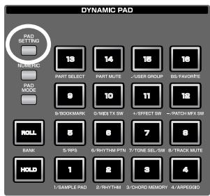
text_image
DYNAMIC PAD PAD SETTING NOMING 13 14 15 16 PART SELECT PART MUTE USER GROUP B5-FAVORATE 0 10 11 16 B/BOOKMARK 0-MET TX SW +EFFECT SW ~/PATCH MFX SW ROLL 8 8 7 8 BANK 5-PPS 6-RHYTHM PTR 7-TONE SEL/SW 8/TRACK MUTE HOLD 1 2 3 4 1-SAMPLE PAD 2-RHYTHM 3/ORDER MEMORY 4-ARFECGO8 TRACK MUTE (Using the Pads to Mute Tracks)
This pad mode allows you to use the pads to directly mute (silence) up to sixteen tracks in the song screen.
1. Press [PAD MODE], and then press pad [8] (TRACK MUTE).
- Pads [1]–[16] correspond to the first sixteen tracks at the top of the song screen.
- Pressing a pad [1]–[16] will switch the corresponding track between muted/play status.
- Each pad will be lit to indicate play status, or blinking to indicate muted.
- You can't use the pads to mute the seventeenth and subsequent tracks. Use [CURSOR] or a USB mouse to switch the mute status of these tracks.
Checking the Pad Status
By pressing [PAD SETTING] you can check the current pad status.
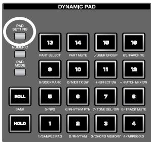
text_image
DYNAMIC PAD PAD SETTING NUMBIG 13 14 15 16 PART SELECT PART MUTE USER GROUP BB/FAVORITE PAD MODE 9 10 11 12 9/BOOKMARK 0/MIDI TX SW /-EFFECT SW ~/PATCH MFX SW ROLL 8 6 7 8 BANK 5/PIP5 6/RYTHM PTN 7/TONE SEL/SW 8/TRACK MUTE HOLD 1 2 3 4 1/SAMPLE PAD 2/RYTHM 3/CHORD MEMORY 4/ARPEGQD9 BOOKMARK (Using the Pads to Recall Frequently Used Screens)
This pad mode lets you use the pads to register and recall frequently used screens. For example if you frequently move between the patch edit screen and effect screen, you can use this function to make the switch easier.
- Press [PAD MODE], and then press pad [9] (BOOKMARK).
Registering a Screen
- Access the screen that you want to register.
- Hold down [PAD SETTING], and press the pad to which you want to register the current screen.
For example if you want to register the current screen to pad [3], the screen will indicate "Bookmarked to #3."
- Press [EXIT].
The setting will be stored.
* If you fail to press [EXIT], the setting will be lost when you turn off the power.
Recalling a Screen
- Press [PAD SETTING].
The Bookmark screen will appear.
Pads to which screens have been registered will lit.
- Press a lit pad, and the screen registered to that pad will be recalled.
* If you want to delete a
registered screen, hold down
[PAD SETTING] in the screen of step 1, and press the pad whose registration you want to clear.
You can press [ROLL] (BANK) to switch banks (1–8). → p. 189
In the Pad Setting screen, you can press [F2 (Pad Exchg)] to exchange two pads (Pad Exchange, p. 190).
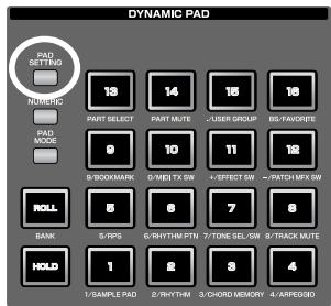
text_image
DYNAMIC PAD PAD SETTING Numeric 13 14 15 16 PART SELECT PART MUTE USER GROUP GS-FAVOREE PAD MODE 9 10 11 12 9/BOOKMARK 9/METI TX SW ~/EFFECT SW ~/PATCH MEX SW NOLL 5 6 7 8 BANK 5/TPS 6/RHYTH PTN 7/TONE SEL/SW 8/TRACK MUTE HOLD 1 2 3 4 1/SAMPLE PAD 2/RHYTH 3/CHORD MEMORY 4/ARPEGID10 MIDI TX SW (Using the Pads to Turn External MIDI Transmit Channels (1-16) On/Off)
This pad mode allows you to use the pads to turn external MIDI transmit channels (1–16) on/off.
-
Press [PAD MODE], and then press pad [10] (MIDI TX SW).
-
Pressing pads [1]–[16] will switch external MIDI transmit channels 1–16 on/off.
- Each pad will be lit when transmission is on, or dark when it is off.
Checking the Pad Status
By pressing [PAD SETTING] you can check the current pad status.
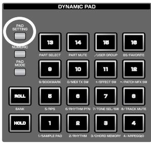
text_image
DYNAMIC PAD PAD SETTING NÚMÍCIC 13 14 15 16 PART SELECT PART MUTE USER GROUP BS-FAVIORETE PAD MODE 9 10 11 12 B/SBOOKMARK O/MIDI TX SW +/-EFFECT SW ~/PATCH MFX SW ROLL 8 8 7 8 BANK 5/IPS 6/RHYTHM PTR 7/TONE SEL/SW 8/TRACK MUTE HOLD 1 2 3 4 1/-SAMPLE PAD 2/RHYTHM 3/CHORD MEMORY 4-/APPROQDNOTE
If numerous MIDI channels are turned on, a large amount of MIDI messages will be transmitted, possibly causing notes to be delayed.
11 EFFECT SW (Using the Pads to Switch the Effects)
This pad mode allows you to use the pads to switch the effects (other than the patch multi-effect) on/off.
1. Press [PAD MODE], and then press pad [11] (EFFECT SW).
- Pressing pads [1]–[6] will switch the following effects on/off.
| Pad | Effect |
| 1 | Input Effect |
| 2 | Chorus |
| 3 | Reverb |
| 4 | Mastering |
| 5 | MFX 1 |
| 6 | MFX 2 (Studio mode only) |
* If you want to turn PFX on/off, use pad mode "12 PATCH MFX SW."
- A pad will be lit when the corresponding effect is on, or blinking when it is off. Pads not used in this pad mode will be dark.
Checking the Pad Status
By pressing [PAD SETTING] you can check the current pad status.
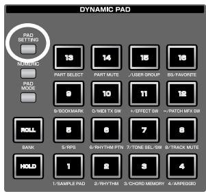
text_image
DYNAMIC PAD PAD SET TIN NIMNIC 13 14 15 16 PART SELECT PART MUTE USER GROUP DIS-FAVORET PAD MODE 8 10 11 9/100KMARK 0/MIDI TX SW /-EFFECT SW ~/PATCH MFX SW ROLL 5/IPS 6/RHYTHM PTN 7/TONE SEL SW 8/TRACK MUTE BANK 5/IPS 6/RHYTHM PTN 7/TONE SEL SW 8/TRACK MUTE HOLD 1 2 3 4 1/SAMPLE PAD 2/RHYTHM 3/CHORD MEMORY 4/ASPEGSD12 PATCH MFX SW (Using the Pads to Switch Patch Multi-effects)
This pad mode allows you to use the pads to individually switch the patch multi-effect of each part (1–16) on/off.
1. Press [PAD MODE], and then press pad [12] (PATCH MFX SW).
- When you press a pad, the patch multi-effect of the corresponding part will be switched on/off. The number of parts will depend on the sound generator mode.
| Mode | Number of parts |
| Single | 1 |
| Live | 8 |
| Studio | 16 |
- A pad will be lit when the corresponding effect is on, or blinking when it is off. Pads not used in this pad mode will be dark.
Checking the Pad Status
By pressing [PAD SETTING] you can check the current pad status.
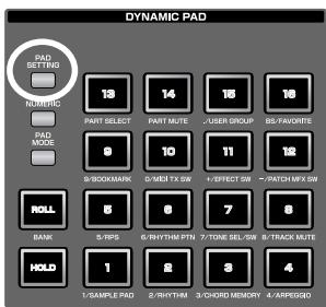
text_image
DYNAMIC PAD PAD SETTING NOMING 13 14 15 16 PART SELECT PART MUTE USER GROUP RS-FAVORATE PAD MODE 9 10 11 12 9-SBOOKMARK G-MET TX SW F-EFFECT SEL 7-PATCH MFX SW ROLL 8 6 7 8 BANK 5/IPS 6/RHYTHM PTN 7-TONE SEL/SW 8-TRACK MUTE HOLD 1 2 3 4 1/SAMPLE PAD 2/RHYTHM 3/CHORD MEMORY 4/APPROVED13 PART SELECT (Using the Pads to Select Parts)
This pad mode allows you to use the pads to select parts (1–16) and banks (INT/EXP1/EXP2/EXT).
1. Press [PAD MODE], and then press pad [13] (PART SELECT).
- Press a pad to select the current part. The number of parts will depend on the sound generator mode.
| Mode | Number of parts |
| Single | 1 |
| Live | 8 |
| Studio | 16 |
- The pad corresponding to the current part will be blinking. The pads for other parts will light. Pads not used will be dark.
- You can press [ROLL] (BANK) to switch banks (1–4). → p. 189
| Pad | Bank name |
| 1 | INT (internal sound generator) |
| 2 | EXP1 (expansion board 1) |
| 3 | EXP2 (expansion board 2) |
| 4 | EXT (external MIDI output) |
* The number of parts on an expansion board will depend on the expansion board.
Checking the Pad Status
By pressing [PAD SETTING] you can check the current pad status.
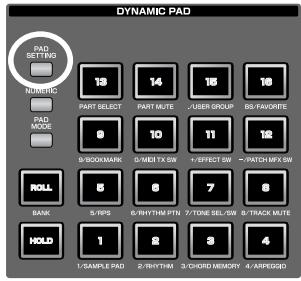
text_image
DYNAMIC PAD PAD SETTING NOMING 13 14 15 16 PART SELECT PART MUTE USER GROUP B5-FAVORITE 9 10 11 12 9/BOOKMARK 0/MIDI TX SW 1/EFFECT SW ~7/PATCH M/FX SW ROLL 8 8 7 8 5/IPS 6/RHYTHM PTR 7/TONE SEL/SW 8/TRACK MUTE HOLD 1 2 3 4 1/SAMPLE PAD 2/RHYTHM 3/CHORD MEMORY 4/ARPEGQO14 PART MUTE (Using the Pads to Mute Parts)
This pad mode lets you use the pads to mute (silence) parts (1–16) and banks (INT/EXP1/EXP2).
1. Press [PAD MODE], and then press pad [14] (PART MUTE).
- You can press [ROLL] (BANK) to switch banks (1–3). → p. 189
| Pad | Bank name |
| 1 | INT (internal sound generator) |
| 2 | EXP1 (expansion board 1) |
| 3 | EXP2 (expansion board 2) |
- Press a pad to switch the corresponding part between muted/play.
* The number of internal sound generator parts will depend on the sound generator mode.
| Mode | Number of parts |
| Single | 3 |
| Live | 8 |
| Studio | 16 |
* The number of parts on an expansion board will depend on the expansion board.
- Pads whose corresponding part is muted will blink. The pads of other parts will be lit. Unused pads will be dark.
Checking the Pad Status
By pressing [PAD SETTING] you can check the current pad status.
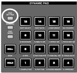
text_image
DYNAMIC PAD PAD SETTING NIMING 13 14 15 16 PART SELECT PART MUTE -USER GROUP BS-FAVORATE 9 10 11 12 S/BOOKMARK G/MET TX SW +EFFECT SW ~/PATCH MEX SW ROLL 8 8 7 8 BANK 5/TIPS 6/RHYTHM PTN 7/TONE SEL SW 8/TRACK MUTE HOLD 1 2 3 4 1/SAMPLE PAD 2/RHYTHM 3/CHORD MEMORY 4/APPEEQ15 USER GROUP (Using the Pads to Register/Recall User Groups)
You can register frequently-used sounds as a user group. This pad mode lets you instantly select these sounds by pressing a pad. You can register sixteen sounds (corresponding to the sixteen pads) in each of four banks, giving you a total of 64 sounds for quick recall. You can register and recall the following user groups, depending on the sound generator mode.
| Mode | User group |
| Single | Patch |
| Live | Live set |
| Studio | Studio set |
MEMO
How User Group differs from Favorite (p. 202)
User Group let you register sounds within the mode (single, live, or studio), while Favorite lets you register settings across modes (single, live, or studio).
Recalling a User Group Sound
-
Press [PAD MODE], and then press pad [15] (USER GROUP).
-
You can press a pad [1]–[16] to select the sound that's registered in that pad.
- By pressing [ROLL] (BANK) you can switch banks (1–4). → p. 189
NOTE
If you want to use the pads to successively select live sets (or studio sets), set the system setting on “Pad Assign Source” (p.292) to “SYS.” If this is set to “TEMP,” the pad mode will switch to the setting of the newly selected live set (or studio set) when you switch live sets (or studio sets).
Registering a Sound in a User Group
- Press [PAD SETTING].
- The User Group screen will appear. Proceed to step 4 of "Registering a sound in the User Group screen," below.
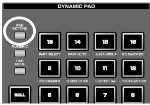
text_image
DYNAMIC PAD PAD SETTING NURRIC 13 14 15 16 PART SELECT PART MUTE USER GROUP BIS FAVORITE 8 10 11 12 S-BOOKMARK C-MET TX SW E-FECTION SW P-ATCH MEX SW ROLL 8 8 7 8Registering a sound in the User Group screen
MEMO
Here's how to register a patch in the patch list screen. Using the same procedure (steps 3 and following), you can use the live set list screen (p. 60) to register a live set in the user group, or the studio set list screen (p. 68) to register a studio set.
- Press [SINGLE] to access the Single Play screen, and select the patch that you want to register (p. 46).
- Press [F1 (Patch List)].
- Press [F6 (User Group)]. The User Group screen will appear.
- Use [F1 (Up)] and [F2 (Down)] to select the destination bank.
- Use [CURSOR] to select the number.
- Press [F5 (Regist)] to register the patch.
- When you've finished registering patches, press [F6 (Exit)] to close the User Group List screen.
TIP
You can press [F8 (Select)] to select a patch and close the User Group screen.
Removing a registered patch
Press [F4 (Remove)] to remove the patch that's selected in the User Group List screen.
16 FAVORITE (Using the Pads to Register/Recall Favorite Settings)
You can create a list of sounds (settings) that you frequently use in live performance, and recall them instantly. You can register patches, rhythm sets, sample sets, live sets, or studio sets, and recall the settings you need for your performance without regard to the mode you might be in.
Sixteen settings can be registered in one list (one bank), and you can create sixteen such banks.
For example you could use bank 1 for the sounds you use in the first song of your live performance, and register up to sixteen sounds in the order in which they are used in your song.
MEMO
How Favorite differs from User Group (p. 201)
User Group let you register sounds within the mode (single, live, or studio), while Favorite lets you register settings across modes (single, live, or studio).
cf.
For details on the Favorite function, refer to “Creating a List of Frequently Used Sounds (Favorite)” (p. 54).
Recalling a Favorite Sound (Setting)
1. Press [PAD MODE], and then press pad [16] (FAVORITE).
- You can press a pad [1]–[16] to select the sound (setting) that's registered in that pad.
- By pressing [ROLL] (BANK) you can switch banks (1–16). → p. 189
![ROLAND FANTOM G8 - Press [PAD MODE], and then press pad [16] (FAVORITE). - 1](/content/2025/01/130804/images/c755351f22fd3d382ab8087e59c864df5e3d91f8f6911990989b11445fe31e50.jpg)
text_image
DYNAMIC PAD PAD SETTING 18 14 15 16 NUMERC PART SELECT PART MUTE -USER GROUP BS-FAVORTE PAD MODE 0 10 11 12 B/DOMMARK 0/MDT TX SW +EFFECT SW ~PATCH-MFX SW ROLL 5 6 7 8 HOLD 1 2 3 4 1/5/6/7/8/9/10/11/12/13/14/15/16/17/18/19/20/21/22/23/24/25/26/27/28/29/30/31/32/33/34/35/36/37/38/39/40/41/42/43/44/45/46/47/48/49/50/51/52/53/54/55/56/57/58/59/60/61/62/63/64/65/66/67/68/69/70/71/72/73/74/75/76/77/78/79/80/81/82/83/84/85/86/87/88/89/90NOTE
If you want to use the pads to successively select live
sets (or studio sets), set the system setting on “Pad Assign Source” (p. 292) to “SYS.” If this is set to “TEMP,” the pad mode will switch to the setting of the newly selected live set (or studio set) when you switch live sets (or studio sets).
Registering a Favorite Sound (Setting)
1. Press [PAD SETTING].
The Favorite screen (p. 54) will appear.
![ROLAND FANTOM G8 - Press [PAD SETTING]. - 1](/content/2025/01/130804/images/8276ed57526984e49c8a475358acabb0b3fa4fcaf5bb439c6997d917566dbaf1.jpg)
text_image
DYNAMIC PAD PAD SETTING NAMBIG 13 14 16 18 PART SELECT PART MUTE USER GROUP BS-FAVORTE B/BOOKMARK G-MET TX SW +EFFECT +PATCH HFX SW ROLL 5/RPS 6/RHYTHM PTR 7/TONE SEL/SW 8/TRACK MUTE HOLD 1 2 3 4cf.
For details on operations in the Favorite screen, refer to "Creating a List of Frequently Used Sounds (Favorite)" (p. 54).
06: Sequencer (Creating a Song)
This chapter explains how to use the sequencer to play, record, and edit songs.
- Playing Back a Song ...... p. 204
- Recording MIDI......p. 217
- Recording Audio......p. 228
• Editing Songs ...... p. 232 - Saving a Song....p. 254
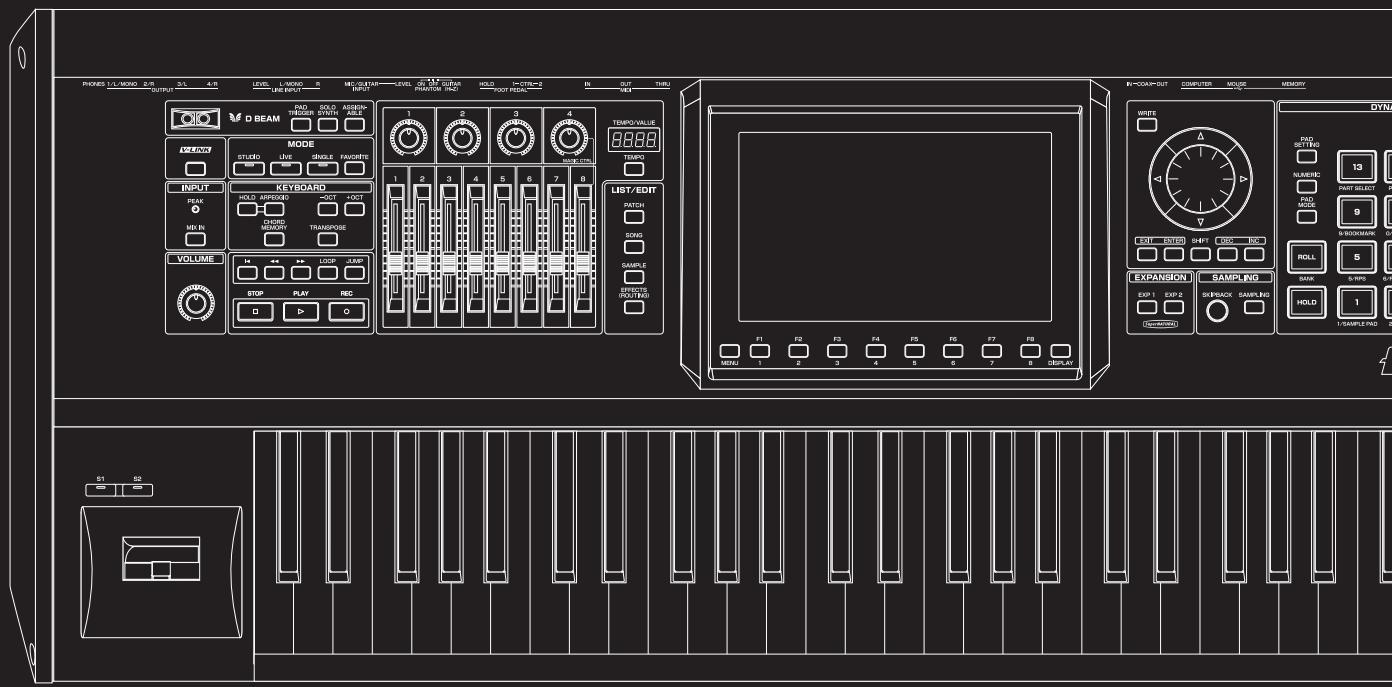
text_image
PROKES L/L MISO 2/R OUTPUT 3/L 4/R LEVEL L-MISO 5 MECUTAIN LEVEL 6 M.1.2 GURAN HOLD I-CTR=2 IN OUT TURU D BEAM RAD TRIGGER SWORD ASSEMB- MODE STUDIO LIVE SINGLE FAUCERS INPUT PEAK HOLD APPROX 3OCT 4OCT CHORD MEOCON TRANSPOSE VOLUME STOP PLAY REC LIST/EDIT MATCH DOYS SAMPLE CAPSIC (RDT/RDS) EXPANSION SAMPLING EXP 1 EXP 2 SREBACK SAMPLING HOLD 1 SAMPLE RAD 2 S1 SB MINI 1 2 3 4 5 6 7 8 DISPLAY IN-COMP-OUT COMPUTER MOUSE MEMORY WIFE PAD SETTING FLAVENIX 13 FAST SELECT 9 BLOODMARK ON ROLL 5 SANK 6-RP0 6-RP1 F1 F2 F3 F4 F5 F6 F7 F8 S1 SBThis section explains how to use the Fantom-G's sequencer to play back a song.
TIP
We recommend that you put the sound generator in Studio mode when creating or playing a song.
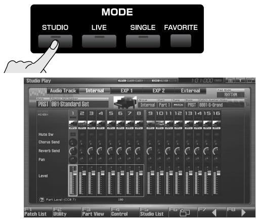
text_image
MODE STUDIO LIVE SINGLE FAVORITE Studio Play Audio Track Internal EXP 1 EXP 2 External PGBT BBI-Standard Set Internal Part 1 PINT POST BBII-G-Standard HADS 1 2 3 4 5 6 7 8 9 10 11 12 13 14 15 16 Hute Sw Chorus Send Reverb Send Pan Level Part Level (CODE 7) 100 Patch List Utility Part View Control Studio List FB F7 FBIn Studio mode you can use up to sixteen sounds to play a different instrument for each part, so this is the ideal mode for playing a song that uses an ensemble of multiple instruments such as drums, bass, and piano.
Three Ways to Play Back
There are three ways to play back: you can play Fantom-G songs, Standard MIDI Files (SMF), or phrases (MIDI Phrases).
Playing a song (p. 204)
You can play Fantom-G songs.
Playing Standard MIDI Files (SMF) (p. 212)
You can copy Standard MIDI Files (SMF) from your computer to the Fantom-G, and play them or import them into a song or phrase.
Playing phrases (MIDI Phrase) (p. 214)
You can audition phrases from within a Fantom-G project.
Playing a Song (Song Play)
Here's how to play a Fantom-G song.
Loading a Song (Song List)
Here's how to access the Song List and load a song from the project.
NOTE
When you load a song, the temporary area (p. 35) of the sound generator will be in the state it was when you created the song. Before loading a song, you should save the patch or live set or studio set that you were editing.
1. Press [SONG].
![ROLAND FANTOM G8 - Press [SONG]. - 1](/content/2025/01/130804/images/64b04ae8d2bfeaadd3880e544a4046d89e8eff5e65e8c892417a43b4d1dd010d.jpg)
The Song Play screen will appear.
2. Press [F1 (Song List)].
The Song List screen will appear.
![ROLAND FANTOM G8 - Press [F1 (Song List)]. - 1](/content/2025/01/130804/images/f64785e64f309d4a2efd711711c4ad85154e257974c61bdf31f0fb088d9e24ef.jpg)
text_image
Song List SONG LIST #001: Fantom G Number Song Name Files 1/58 001 Fantom G FantomG SVG 002 INIT SONG 003 INIT SONG 004 INIT SONG 005 INIT SONG 006 INIT SONG 007 INIT SONG 008 INIT SONG 009 INIT SONG 010 INIT SONG 011 INIT SONG 012 INIT SONG F4 Delete Song F7 FB Exit LoadF-key operations in the Song List screen
| F-key | Explanation | Page |
| F4Delete Song | Deletes a song file from the project. | p. 210 |
| F7Exit | Returns to the previous screen. | - |
| F8Load | Loads the song file. | p. 204 |
- Turn the VALUE dial, or use [INC] [DEC], or use ▲ / ▼ to select a song.
- Press [F8 (Load)].
A confirmation message will appear.
- Press [F7 (OK)].
If you decide to cancel, press [F8 (Exit)].
Playing a Song (Song Play)
Here's how to play the song you loaded in the Song Play screen (p. 204).
1. Press [SONG].
![ROLAND FANTOM G8 - Press [SONG]. - 1](/content/2025/01/130804/images/d20fdb9f1fb581f526cedddec78409f52147eb9ca67207bc9c7865b5606feb58.jpg)
The Song Play screen will appear.
![ROLAND FANTOM G8 - Press [SONG]. - 2](/content/2025/01/130804/images/498c292179e696609bfdabb6147e3082d000627457a5e03997fbf10a1980866d.jpg)
text_image
Song Play 001-Fantom G Track Name: Term/No: Out Span: Rate 1 MIDI Track 1 PHASE 625000 2 MIDI Track 1 PHASE 625000 3 MIDI Track 1 PHASE 625000 4 MIDI Track 1 PHASE 625000 5 MIDI Track 1 PHASE 625000 6 MIDI Track 1 PHASE 625000 7 MIDI Track 1 PHASE 625000 8 MIDI Track 1 PHASE 625000 9 S Sep10001 MFX2 625000 10 S Sep10002 MFX2 625000 11 S Sep10003 MFX2 625000 12 S Sep10004 MFX2 625000 13 MFX2 625000 14 MFX2 625000 15 MFX2 625000 16 MFX2 625000 Current Track Track 881(MIDI Track88) F1 Song List SMF List Phrase List Studio Play Loop F6 Marker F7 Song Util Song EditF-key operations in the Song Play screen
| F-key | Explanation | Page | |
| F1Song List | Displays the Song List, where you can load a song. | p. 204 | |
| F2SMF List | Displays the SMF List, where you can play or import SMF data. | p. 212 | |
| F3Phrase List | Displays the MIDI Phrase List, where you can audition or edit phrases. | p. 214 | |
| F4Studio Play/ Live Play/ Single Play | Displays the Studio Play/Live Play/Single Play screen. | - | |
| F5Loop | Opens the Loop window, where you can specify the loop region. | p. 208 | |
| F6Marker | Opens the Marker window, where you can set markers. | p. 208 | |
| F7Song Util | Zoom/ Track Order | Zooms in/out on the track, and changes the order in which the tracks are displayed. | p. 209 |
| Song Clear | Erases the song. | p. 211 | |
| Track Clear | Erases the track. | p. 235 | |
| Track Name | Assigns a name to the track. | p. 235 | |
| Track Edit Insert | Inserting a Blank Measure | p. 237 | |
| Track Edit Delete | Deleting Unwanted Measures | p. 237 | |
| Track Edit Copy | Copying Measures | p. 237 | |
| Tempo Track | Changes the tempo. | p. 235 | |
| Beat Track | Changes the time signature. | p. 236 | |
| Save As SMF | Save As an SMF File | p. 256 | |
| F8Song Edit | Opens the Song Edit screen, where you can edit a song. | p. 232 | |
SHIFT + F-keys operations in the Song Play screen
| F-key | Explanation | Page |
| SHIFT + F1 Trk Edit Ins | Inserting a Blank Measure | p. 237 |
| SHIFT + F2 Trk Edit Del | Deleting Unwanted Measures | p. 237 |
| SHIFT +F3 Trk Edit Copy | Copying Measures | p. 237 |
| SHIFT +F8 Zoom | Zooms the track display, or changes the displayed order of the tracks. | p. 209 |
2. Press [PLAY] to start playback.
![ROLAND FANTOM G8 - Press [PLAY] to start playback. - 1](/content/2025/01/130804/images/1ac0c796c4f80b9cce2dba73790a51f7f21fcbe48408ff4f7b4c47c626b85ab0.jpg)
Playback will stop automatically when the song ends. If you want to stop before the end of the song, press [STOP].
Operations in the Song Play Screen
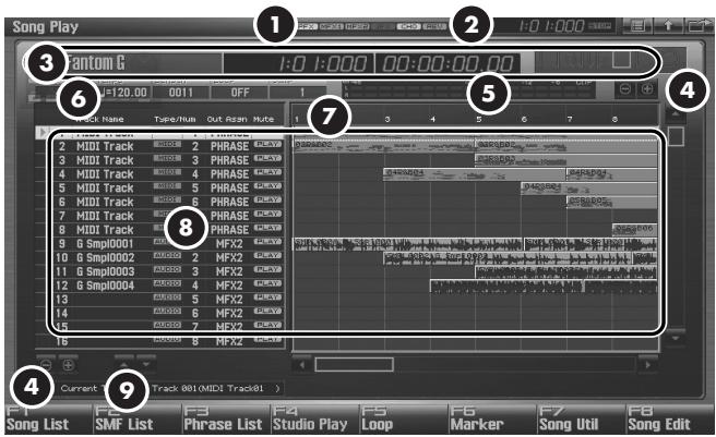
text_image
Song Play 1:0 1:000 00:00:00.00 2 1:0 1:000 3 Phantom G 4 1:0 1:000 00:00:00.00 5 1:0 1:000 00:00:00.00 6 1:120.00 0011 OFF 7 1:120.00 0011 OFF 8 1:120.00 0011 OFF 9 1:120.00 0011 OFF 10 1:120.00 0011 OFF 11 1:120.00 0011 OFF 12 1:120.00 0011 OFF 13 1:120.00 0011 OFF 14 1:120.00 0011 OFF 15 1:120.00 0011 OFF 16 1:120.00 0011 OFF 17 1:120.00 0011 OFF 18 1:120.00 0011 OFF 19 1:120.00 0011 OFF 2 MIDI Track 2 PHRASE 4X8X8 3 MIDI Track 3 PHRASE 4X8X8 4 MIDI Track 4 PHRASE 4X8X8 5 MIDI Track 5 PHRASE 4X8X8 6 MIDI Track 6 PHRASE 4X8X8 7 MIDI Track 7 PHRASE 4X8X8 8 MIDI Track 8 PHRASE 4X8X8 9 SmpI0001 MFX2 4X8X8 10 SmpI0002 MFX2 4X8X8 11 SmpI0003 MFX2 4X8X8 12 SmpI0004 MFX2 4X8X8 13 MFX2 4X8X8 14 MFX2 4X8X8 15 MFX2 4X8X8 16 MFX2 4X8X8 17 MFX2 4X8X8 18 MFX2 4X8X8 19 MFX2 4X8X8 Current Track (MIDI Track) F1 F2 F3 F4 F5 F6 F7 F8 Song List SMF List Phrase List Studio Play Loop Marker Song Util Song Edit| Number | Explanation |
| 1 | Indicates the on/off status of each effect.PFX Patch multi-effectMFX1 Multi-effect 1MFX2 Multi-effect 2IFX Input effectCHO ChorusREV ReverbMAS Mastering effect |
| 2 | Indicates the current location of the song, and the status of the sequencer. |
| 3 | Indicates the number and name of the currently selected song, the current location, and the status of the sequencer. |
| 4 | Track zoom button (for a USB mouse). |
| 5 | Level meter for the Output jacks. |
| 6 | Indicates the song's time signature, tempo, and loop play on/off status. |
| 7 | Indicates markers and measures. |
| 8 | Indicates the track name and track information. |
| 9 | Track order change button (for USB mouse). |
Selecting a Sound (Part or Patch) in the Song Screen
In the Song Play/Song Edit screen, you can select a part or patch by pressing [PATCH].
1. In the Song Play/Song Edit screen, press [PATCH].
The Part Select window will appear.
Use ◀ / ▶ to move the cursor, and use the VALUE dial or [INC] [DEC] to change the value.
| Value | Explanation |
| Group | Part Group |
| Part | Part |
| Type | Patch Type |
| Bank | Patch Bank |
| Patch Number/Name | Patch Number/Name |
| F-Key | Explanation |
| F5Patch Edit | Edit a patch. |
| F6Patch List | Open the Patch List screen. |
| F7Rehearsal(displayed only during recording) | Audition Sounds(Rehearsal Function) |
| F8Close | Close the Part Select window. |
NOTE
If you change the part during recording, the recording track will not change even if the Auto Track function (p. 222) is on.
Fast-forwarding or Rewinding during Playback
You can fast-forward, rewind, or jump within a song not only while the song is stopped, but also during playback. Perform the following actions.
Fast-forward: Press [▶▶]
Continue fast-forwarding: Hold down [▶▶]
Fast-forward rapidly: Press [▶▶] and then press [◀◀]
Rewind: Press [◀◀]
Continue rewinding: Hold down [◀◀]
Rewind rapidly: Press [◀◀] and then press [▶▶]
Jump to the preceding marker: Hold down [SHIFT] and press [◀◀]
Jump to the next marker: Hold down [SHIFT] and press [▶▶]
Jump to the beginning of the song: Press [◀]
Jump to the JUMP marker: Press [JUMP]
NOTE
Song playback will pause if you jump to the beginning or end of the song while playing-back.
Muting the Playback of a Track (MUTE)
You can mute a track so that it will not produce sound during playback.
- Press [SONG].
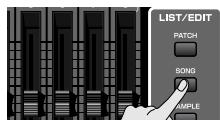
The Song Play screen will appear.
-
Turn the VALUE dial or use ▲ / ▼ to select the track that you want to mute.
-
Use ◀ / ▶ to move the cursor to "PLAY."
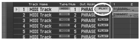
text_image
Track Name Type/Num Out Assign 1 2 1 MIDI Track MIDI 1 PHRASE PLAY 01P2B01 2 MIDI Track MIDI 2 PHRASE PLAY 02P2B02 3 MIDI Track MIDI 3 PHRASE PLAY 4 MIDI Track MIDI 4 PHRASE PLAY 5 MIDI Track MIDI 5 PHRASE PLAY 6 MIDI Track MIDI 6 PHRASE PLAY- Press [DEC] to select the "MUTE" setting.
cf.
You can also use the pads to switch the track muting.
→ “8 TRACK MUTE (Using the Pads to Mute Tracks)” (p. 197)
Accessing the Mixer Screen
For a song you've created in Studio mode, you can use the Studio mode Studio Play screen to adjust the volume of each internal sound generator part and audio track.
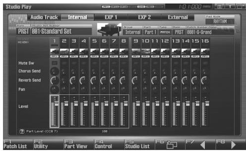
text_image
Studio Play Audio Track Internal EXP 1 EXP 2 External PRST 0001-Standard Set REDB1 1 2 3 4 5 6 7 8 9 10 11 12 13 14 15 16 Mute Sw Chorus Send Reverb Send Pam Level Part Level (CCT 7) 100 F1 F2 F3 F4 F5 F6 F7 F8 Patch List Utility Part View Control Studio List
For details on operation, refer to “Displaying Studio Play Screen” (p. 66).
Changing the Playback Tempo of the Song
When a song plays back, its tempo is determined by the data in the tempo track, but you can also adjust the tempo of the overall song during playback. This adjustment is called the " playback tempo."
NOTE
The playback tempo is a temporary setting. It will be lost when you switch to a different song or turn off the power. If you want the song to always play at this tempo, you must re-save the song (p. 254).
MEMO
The tempo is stored on an individual Live/Studio Set basis. Using “Tempo Assign Source” (p. 296), you can choose to have the tempo follow the setting of each Live/Studio Set (TEMP), or follow the Fantom-G’s global settings (SYS).
1. Press [TEMPO].
The Tempo window will appear.
![ROLAND FANTOM G8 - Press [TEMPO]. - 1](/content/2025/01/130804/images/4a6b8a31ef2e52b0e31d87aa1c1ef6d4b834f702a7c41204b66c6a519fdb9b9d.jpg)
text_image
Tempo Tempo J=120.00 F6 F7 F8 Tap Tempo Click Close2. Turn the VALUE dial or use [INC] [DEC] to specify the playback tempo. By holding down [SHIFT] and turning the VALUE dial you can make fine adjustments below the decimal point.
- If you press [F7 (Click)] to turn it on, a click will sound at the specified tempo. The click will turn on/off each time you press the button.
- You can specify the tempo by pressing [F6 (Tap Tempo)] at the desired interval (Tap Tempo). Press the button at least three times at quarter-note intervals of the desired playback tempo.
3. When you've finished making settings, press [F8 (Close)].
Playing a Song Repeatedly (Loop)
You can make the song play repeatedly according to the loop points you specify.
NOTE
You can't specify loop points for a phrase.
- Press [SONG].
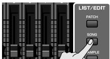
The Song Play screen will appear.
- Press [F5 (Loop)].
The Loop window will appear.
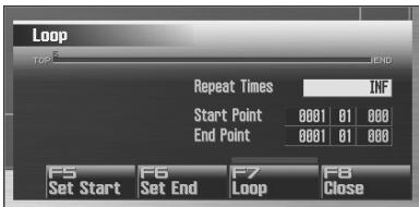
text_image
Loop T00 END Repeat Times INF Start Point 0001 01 000 End Point 0001 01 000 F5 F6 F7 F8 Set Start Set End Loop Close- Move the cursor to the desired parameter, and turn the VALUE dial or use [INC] [DEC] to set the value.
* Stop the sequencer before you make these settings. You can make these settings if the sequencer is running.
- Repeat Times
Specifies the number of times (1–99) that the specified region will repeat. If you want it to repeat until you press [STOP], choose "INF."
- Start Point
Specifies the starting point of the loop region.
If you press [F5 (Set Start)], the current location in the song will be specified as the loop start point.
- End Point
Specifies the ending point of the loop region. The location you specify is not included in the loop region.
If you press [F6 (Set End)], the current location in the song will be specified as the loop end point.
- To enable the loop settings, press [F7 (Loop)] to turn it on.
MEMO
You can use the [LOOP] button on the panel to turn looping on/off.
MEMO
You can open this screen by holding down [SHIFT] and pressing [LOOP].
- Press [F8 (Close)] to close the window.
Placing Markers in a Song (Marker)
You can place up to sixteen markers in a song at units of one measure. This will make song editing easier, since it will be easier for you to see the structure of your song, or to move quickly to the location of a marker.
Here's how to view and edit a list of the markers in a song.
- Press [SONG].
The Song Play screen will appear.
- Press [F6 (Marker)].
The Marker window will appear.
The buttons perform the following operations.
- VALUE dial, [INC] [DEC], ▲ ▼ Select a marker within the list. The current location also will be jumped.
- [F4 (Name)] Assigns a name to the currently selected marker. Choose a name from the displayed list, and press [F8 (Select)] to finalize your choice.
• [F5 (Set)]
Adds a marker at the beginning of the current measure.
• [F6 (Clear)]
Deletes the selected marker.
• [F7 (Jump)]
Specifies the marker to which you will move when you press the front panel [JUMP] button.
- Press [F8 (Close)] to close the window.
MEMO
When the Marker window is open, you can press a pad 1–16 to jump to the marker of the corresponding number.
MEMO
You can open this screen by holding down [SHIFT] and pressing [JUMP].
Jumping to a marker
Here's how to jump to markers within a song.
Jumping to the previous marker:
Hold down [SHIFT] and press [◀◀].
Jumping to the next marker:
Hold down [SHIFT] and press [▶▶].
Jumping to the beginning of the song:
Press [ ◀ ].
Jumping to the JUMP marker:
Press [JUMP].
Changing the Track Display Zoom and Display Order (Zoom/Track Order)
Here's how to change the zoom ratio of the track display, and change the order in which tracks are displayed.
1. Press [SONG].
The Song Play screen will appear.
2. Press [F7 (Song Util)].
The Song Utility Menu window will appear.
MEMO
In the Song Play/Song Edit screen, you can also access the Song View window by holding down [SHIFT] and pressing [F8].
3. Use ▲ / ▼ to choose "Zoom/Track Order," and press [F8 (Select)].
To cancel, press [F7 (Cancel)].
The Zoom/Track Order window will appear.
Changing the track display zoom
4. Use [CURSOR] to change the zoom ratio.
• Horizontal axis (time axis of the tracks)
Press ◀ to shrink the display.
Press ▶ to magnify the display.
• Vertical axis (vertical axis of the tracks)
Press ▲ to magnify the display.
Press ▼ to shrink the display.
Even without accessing the zoom window, you can hold down [SHIFT] in the Song Play screen and zoom the horizontal axis in/out by pressing ◀ or ▶ or zoom the vertical axis in/out by pressing [INC] or [DEC].
MEMO
If you're using a USB mouse, you can change the zoom in the Song Play screen by clicking the buttons shown in the illustration.
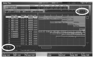
text_image
Audio Play Track List GND List Phase List Loop Marker Play Song Web Send Edit Add Add Add Add Add Add Add Add Add Add Add Add Add Add Add Add Add Add Add Add Add Add Add Add Add Add Add Add Add Add Add Add Add Add Add Add Add Add Add Add Add Add Add Add Add Add Add Add Add Add EditChanging the track display order
- By turning the VALUE dial or using [INC] [DEC] to change the value in the "Track Order" field, you can change the order in which the currently selected track is displayed.
MEMO
If you're using a USB mouse, you can also change the track display order from the Song Play screen by clicking the button shown in the illustration.
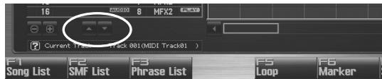
text_image
16 8 MFX2 Current Track - Track 001(MIDI Track01) F1 Song List F2 SMF List F3 Phrase List F5 Loop F6 Marker- Press [F8 (Close)] to close the Zoom/Track Order window.
Naming a Track (Track Name)
Here's how to assign a name of a track.
MEMO
In the Song Play/Song Edit screen when the track name is blank, the first-recorded patch name (or for an audio track, the sample name) will automatically be the track name.
- Press [SONG].
The Song Play screen will appear.
-
Turn the VALUE dial or use ▲ / ▼ to select the track you want to name.
-
Use ◀ / ▶ to move the cursor to the track name field.
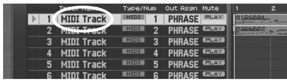
text_image
Track Name Type/Num Out Assn Mute 1 MIDI Track MIDI 1 PHRASE PLAY 2 MIDI Track MIDI 2 PHRASE PLAY 3 MIDI Track MIDI 3 PHRASE PLAY 4 MIDI Track MIDI 4 PHRASE PLAY 5 MIDI Track MIDI 5 PHRASE PLAY 6 MIDI Track MIDI 6 PHRASE PLAY-
Press [ENTER].
-
Assign the desired name.
cf.
For details on entering a name, refer to “Assigning a Name” (p. 42).
- Press [F8 (Write)] to finalize the name.
Specifying a Track's Output Destination (Output Assign)
Here's how to specify the output destination of each track.
- Press [SONG].
The Song Play screen will appear.
-
Turn the VALUE dial or use ▲ / ▼ to select the track whose output destination you want to assign.
-
Use ◀ / ▶ to move the cursor to the location shown in the illustration.
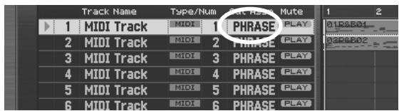
text_image
Track Name Type/Num Rate/Play Mute 1 MIDI Track MIDI 1 PHRASE PLAY 2 MIDI Track MIDI 2 PHRASE PLAY 3 MIDI Track MIDI 3 PHRASE PLAY 4 MIDI Track MIDI 4 PHRASE PLAY 5 MIDI Track MIDI 5 PHRASE PLAY 6 MIDI Track MIDI 6 PHRASE PLAY- Use [INC] [DEC] to specify the output destination.
For a MIDI track
PHRASE: Output according to the setting recorded in the phrase. Normally you will choose this.
INT: Play the Fantom-G's internal sound generator.
EXT: Play an external sound module connected to the MIDI OUT connector.
BOTH: Play the Fantom-G's internal sound generator and an external sound module connected to the MIDI OUT connector.
EXP1: Play expansion board ARX1.
EXP2: Play expansion board ARX2.
OFF: Nothing will be played.
For an audio track
OUT A, OUT B:
Output the sound in stereo from the OUTPUT A (MIX) jacks or OUTPUT B jacks without sending it through the multi-effect.
MFX1-2: Send the sound through the multi-effect, and output it in stereo. This also allows you to apply chorus or reverb to the sound that has passed through the multi-effect.
Deleting a Song File (Song Delete)
Here's how to delete a song file from the project.
- Press [SONG].
The Song Play screen will appear.
- Press [F1 (Song List)].
The Song List screen will appear.
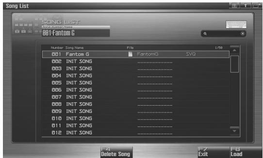
text_image
Song List SONG LIST Stocksource 001 Fantom G Number Song Name File 1/59 001 Fantom G FantomG SVG 002 INIT SONG 003 INIT SONG 004 INIT SONG 005 INIT SONG 006 INIT SONG 007 INIT SONG 008 INIT SONG 009 INIT SONG 010 INIT SONG 011 INIT SONG 012 INIT SONG F4 Delete Song F7 F8 Exit Load-
Turn the VALUE dial or use [INC] [DEC] or ▲ / ▼ to select the song that you want to delete.
-
Press [F4 (Delete Song)].
A confirmation message will appear.
- Press [F7 (OK)] to execute the operation.
If you decide to cancel, press [F8 (EXIT)].
Song Automatically Loaded at Power-on (When Loading a Project)
When the Fantom-G is powered-on (when loading a project), song 001 (the top song in the Song List) will be loaded automatically.
TIP
If you don't want a song to be loaded automatically at power-on (when loading a project), delete song 001 as described in "Deleting a Song File (Song Delete)" (p. 210).
TIP
When you execute a Factory Reset (p. 284), the demo song will be written to song 001.
Erasing the Currently-open Song (Song Clear)
Here's how to erase the song that's currently opened in the Song Play screen. Use this function when you want to record a new song. This will not delete the actual song file that's saved in the project.
NOTE
If a song you're editing is open, save the song before you continue (p. 254).
- Press [SONG].
The Song Play screen will appear.
- Press [F7 (Song Util)].
The Song Utility Menu window will appear.
- Use ▲ / ▼ to choose "Song Clear," and press [F8 (Select)].
To cancel, press [F7 (Cancel)]. A confirmation message will appear.
- Press [F7 (OK)] to execute.
If you decide not to execute, press [F8 (EXIT)].
Playing a Standard MIDI File (SMF)
Standard MIDI File (SMF) data from your computer can be copied to the Fantom-G for listening, or imported into a song or phrase.
Copying a Standard MIDI File (SMF) from Your Computer to the Fantom-G
Here's how to copy a standard MIDI file from your computer to the Fantom-G.
- Prepare a standard MIDI file (.MID) on your computer.
- Use the USB Storage function (p. 285) to copy the standard MIDI file (.MID) to the following folder of the Fantom-G's internal memory or of your USB memory.
"FantomG.Prj/SEQ/SMF" folder
MEMO
"FantomG.Prj" will be the project folder name in the Fantom-G's internal memory. You can save more than one project in USB memory. By default, the project folders will be named consecutively as "FantomG001.Prj."
"FantomG002.Prj," etc., and the portion of the name preceding the file name extension will be the project name you assigned when saving the file.
Playing a Standard MIDI File (SMF) (SMF List)
You can access the SMF List and listen to a standard MIDI file (SMF) that you copied as described in “Copying a Standard MIDI File (SMF) from Your Computer to the Fantom-G” (p. 212).
TIP
When playing SMF data, we recommend that you put the sound generator in Studio mode. The Fantom-G is GM/GM2 compatible, so if the music data is compatible with GM/GM2, it will automatically play back with the appropriate sounds.
- Press [SONG].
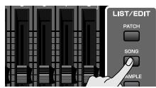
The Song Play screen will appear.
- Press [F2 (SMF List)].
The SMF List screen will appear.
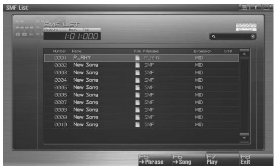
text_image
SMF List 1:0 1:000 Number Name File Filename Extension L/18 0001 P.RHY F.RHY MID 0002 New Song SMF MID 0003 New Song SMF MID 0004 New Song SMF MID 0005 New Song SMF MID 0006 New Song SMF MID 0007 New Song SMF MID 0008 New Song SMF MID 0009 New Song SMF MID 0010 New Song SMF MID F5 F6 F7 F8 →Phrase →Song Play ExitF-key operations in the SMF List screen
| F-key | Explanation | Page |
| F5-> Phrase | Imports an SMF file into a phrase. | p. 213 |
| F6-> Song | Imports an SMF file into a song. | p. 213 |
| F7Play | Plays the SMF file selected in the list. | p. 212 |
| F8EXIT | Returns to the previous screen. | - |
- Turn the VALUE dial or use [INC] [DEC] or ▲ / ▼ to select an SMF file.
- Press [PLAY] or [F7 (Play)].
You will hear the selected SMF file.
Importing an SMF into a Phrase (Import Phrase)
You can access the SMF List and import a standard MIDI file (SMF) from the project into a phrase. You can then use the imported SMF as a phrase.
- Press [SONG].
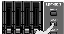
The Song Play screen will appear.
- Press [F2 (SMF List)].
The SMF List screen will appear.
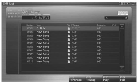
text_image
SMF List 1:0 1:000 Number Name File Filename Extension 1/18 0001 P_HRY P_HRY MID 0002 New Song SMF MID 0003 New Song SMF MID 0004 New Song SMF MID 0005 New Song SMF MID 0006 New Song SMF MID 0007 New Song SMF MID 0008 New Song SMF MID 0009 New Song SMF MID 0010 New Song SMF MID F5 F6 F7 FB →Phrase →Song Play Exit-
Turn the VALUE dial or use [INC] [DEC] or ▲ / ▼ to select an SMF file.
-
Press [F5 (->Phrase)].
A confirmation message will appear.
- Press [F7 (OK)] to execute.
If you decide to cancel, press [F8 (EXIT)].
When you execute, the selected SMF file will automatically be imported into a vacant number of the phrase list, and the Phrase Edit screen (p. 238) will appear.
MEMO
The imported phrase is temporary, and will be lost if you turn off the power. If you want to keep the phrase, press [WRITE] to save it (p. 216).
Importing an SMF into a Song (Import Song)
You can access the SMF List and import a standard MIDI file (SMF) from the project into a song. You can then use the imported SMF as a Fantom-G song.
- Press [SONG].
The Song Play screen will appear.
- Press [F2 (SMF List)].
The SMF List screen will appear.
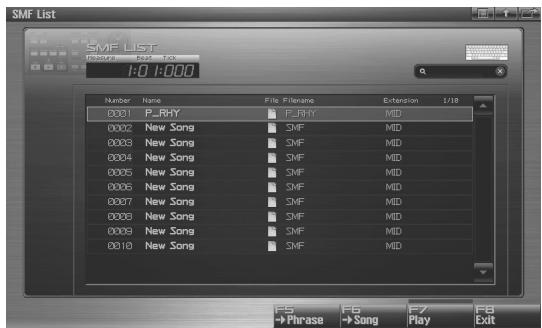
text_image
SMF List 1:0 1:000 Number Name File Filename Extension 1/18 0001 P_RHY P_RHY MID 0002 New Song SMF MID 0003 New Song SMF MID 0004 New Song SMF MID 0005 New Song SMF MID 0006 New Song SMF MID 0007 New Song SMF MID 0008 New Song SMF MID 0009 New Song SMF MID 0010 New Song SMF MID F5 F6 F7 F8 →Phrase →Song Play Exit-
Turn the VALUE dial or use [INC] [DEC] or ▲ / ▼ to select an SMF file.
-
Press [F6 (->Song)].
A confirmation message will appear.
- Press [F7 (OK)] to execute.
If you decide to cancel, press [F8 (EXIT)].
When you execute, the selected SMF file will automatically be imported into a vacant number of the song list, and the Song Play screen (p. 205) will appear.
MEMO
The imported song is temporary, and will be lost if you turn off the power. If you want to keep the song, press [WRITE] to save it (p. 254).
Playing Phrases (MIDI Phrase)
Phrases from within the Fantom-G project can be auditioned from a list.
Auditioning a Phrase (MIDI Phrase List)
Here's how to access the Phrase List and audition a phrase from the project.
1. Press [SONG].
![ROLAND FANTOM G8 - Press [SONG]. - 1](/content/2025/01/130804/images/84fed1114d46dfa9e8d7d1e11fa7daa9b7c2d1f5280cfe25f9e4d722cf07b8f5.jpg)
The Song Play screen will appear.
2. Press [F3 (Phrase List)].
The MIDI Phrase List screen will appear.
![ROLAND FANTOM G8 - Press [F3 (Phrase List)]. - 1](/content/2025/01/130804/images/19acebc73bed811cdfe31cf12cc681c07b3096ffe1fa2bca33a8e2791fea68c7.jpg)
text_image
MIDI Phrase List MIDI PHRASE LIST 0:0 1:000 Number Phrase Name P16 6/2008 0006 05R&B05 0006 SVP 0007 07R&B07 0007 SVP 0008 08R&B08 0008 SVP 0009 09R&B09 0009 SVP 0010 10HipHp1 0010 SVP 0011 11HipHp2 0011 SVP 0012 12R&B10 0012 SVP 0013 13Pop1 0013 SVP 0014 14HipHp3 0014 SVP 0015 15Pop2 0015 SVP 0016 16R&B11 0016 SVP 0017 17HipHp1 0017 SVPF-key operations in the MIDI Phrase List screen
| F-key | Explanation | Page | |
| F1Load | Loads a phrase from the project into memory. | p. 214 | |
| F2Save | Saves the selected phrase to the project. | p. 216 | |
| F3Util Menu | Save All | Save all phrases | p. 216 |
| Delete Phrase | Deletes the phrase file from the project | p. 215 | |
| Duplicate | Duplicates the phrase | p. 215 | |
| F6Edit | Returns to the previous screen. | - | |
| F7Preview | Auditions the selected phrase. | p. 214 | |
| F8Phrase Edit | Displays the edit screen for the selected phrase. | p. 238 | |
3. Turn the VALUE dial or use [INC] [DEC] or ▲ / ▼ to select a phrase.
4. Press and hold [F7 (Preview)].
You'll hear the selected phrase.
Loading a Phrase (Load)
Here's how to load a phrase from the project into memory.
1. Press [SONG].
![ROLAND FANTOM G8 - Press [SONG]. - 1](/content/2025/01/130804/images/f97485757219c79c5ec383e274bd995be26ca5bdadf30b74ec8745c3f2e3f8a0.jpg)
The Song Play screen will appear.
2. Press [F3 (Phrase List)].
The MIDI Phrase List screen will appear.
![ROLAND FANTOM G8 - Press [F3 (Phrase List)]. - 1](/content/2025/01/130804/images/515bc47ccc6fc2cdb98ab88a4f57f0730272e9496dfd044d11b02fffa27d9925.jpg)
text_image
MIDI Phrase List MIDI PHRASE LIST 0:0 1:000 Number Phrase Name Pfd 5/2000 0006 05R&805 0036 SVP 0007 07R&807 0007 SVP 0008 08R&808 0008 SVP 0009 09R&809 0039 SVP 0010 10HipHp1 0010 SVP 0011 11HipHp2 0011 SVP 0012 12R&810 0012 SVP 0013 13Pop1 0013 SVP 0014 14HipHp3 0014 SVP 0015 15Pop2 0015 SVP 0016 16R&811 0016 SVP 0017 51HipHp1 0017 SVP3. Turn the VALUE dial or use [INC] [DEC] or ▲ / ▼ to select a phrase.
4. Press [F1 (Load)].
A confirmation message will appear.
5. Press [F7 (OK)] to execute.
If you decide to cancel, press [F8 (EXIT)].
The phrase list shows the current phrase status
| Phrase name | This shows the phrase name. If this field indicates “EMPTY,” the phrase has not been loaded into memory. Load the phrase as needed. |
| [30X3] | This indicates whether the file exists in the project. Phrases without the symbol have not been saved, and therefore will be lost when you turn off the power. Save the phrase if necessary. |
| [47YZ] | This indicates a phrase that has been edited. The changes you made will be lost when you turn off the power. Save the phrase if necessary. |
Deleting a Phrase from the Project (Delete Phrase)
This operation will completely delete a phrase from the project along with its file.
NOTE
If that phrase is used by a song within the project, the portion of the song occupied by that phrase will no longer sound.
1. Press [SONG].
![ROLAND FANTOM G8 - Press [SONG]. - 1](/content/2025/01/130804/images/155bb87b324533c7d5cc7a3525e9a29ee1de8c30f383b7fd58dabdfd0323b70c.jpg)
The Song Play screen will appear.
2. Press [F3 (Phrase List)].
The MIDI Phrase List screen will appear.
![ROLAND FANTOM G8 - Press [F3 (Phrase List)]. - 1](/content/2025/01/130804/images/45528f0f476f8f799d7508c24da95e6458de70ccf6261f74387356210239ea28.jpg)
text_image
MIDI Phrase List MIDI PHRASE LIST 1:0 1:000 Number Phrase Name P16 6/2008 0006 05R&B05 0005 SVP 0007 07R&B07 0007 SVP 0008 08R&B08 0008 SVP 0009 09R&B09 0009 SVP 0010 10HipHp1 0010 SVP 0011 11HipHp2 0011 SVP 0012 12R&B10 0012 SVP 0013 13Pop1 0013 SVP 0014 14HipHp3 0014 SVP 0015 15Pop2 0015 SVP 0016 16R&B11 0016 SVP 0017 17HipHp1 0017 SVP3. Turn the VALUE dial or use [INC] [DEC] or ▲ / ▼ to select a phrase.
4. Press [F3 (Util Menu)].
The Phrase Utility Menu window will appear.
5. Use ▲ / ▼ to choose "Delete Phrase," and press [F8 (Select)].
To cancel, press [F7 (Cancel)].
A confirmation message will appear.
6. Press [F7 (OK)].
If you decide to cancel, press [F8 (EXIT)].
Duplicating a Phrase (Duplicate)
This operation will duplicate a phrase to a vacant number in the list. You can use this to create variations by modifying an existing phrase.
1. Press [SONG].
![ROLAND FANTOM G8 - Press [SONG]. - 1](/content/2025/01/130804/images/944b0d3f1277226c0321ba39b2228e2e65c0bb20b6c77c82f9f1579da9e2c246.jpg)
The Song Play screen will appear.
2. Press [F3 (Phrase List)].
The MIDI Phrase List screen will appear.
![ROLAND FANTOM G8 - Press [F3 (Phrase List)]. - 1](/content/2025/01/130804/images/81a1479d0b28efab89c76074d3b9cf0d6d9cfde2dfb7710896d45e2ced37b8d0.jpg)
text_image
MIDI Phrase List MIDI PHRASE LIST 0:0 1:000 Number Phrase Name Pigs 6/2000 0006 05R&B06 0005 SVP 0007 07R&B07 0007 SVP 0008 08R&B08 0008 SVP 0009 09R&B09 0009 SVP 0010 10HipHp1 0010 SVP 0011 11HipHp2 0011 SVP 0012 12R&B10 0012 SVP 0013 13Pop1 0013 SVP 0014 14HipHp3 0014 SVP 0015 15Pop2 0015 SVP 0016 16R&B11 0016 SVP 0017 17HipHp1 0017 SVP3. Turn the VALUE dial or use [INC] [DEC] or ▲ / ▼ to select a phrase.
4. Press [F3 (Util Menu)].
The Phrase Utility Menu window will appear.
5. Use ▲ / ▼ to choose "Duplicate," and press [F8 (Select)].
To cancel, press [F7 (Cancel)].
A confirmation message will appear.
6. Press [F7 (OK)] to execute.
If you decide to cancel, press [F8 (EXIT)].
When you execute, the selected phrase will automatically be duplicated to a vacant number in the phrase list.
Saving a Phrase (Save)
This operation will save the selected phrase to the project.
A phrase you recorded or edited is temporary, and will be lost when you turn off the power. If you want to keep the phrase, you must save it.
- Press [SONG].
- Press [F3 (Phrase List)].
The MIDI Phrase List screen will appear.
Phrases without the symbol and phrases with the symbol have not been saved.
-
Turn the VALUE dial or use [INC] [DEC] or ▲ / ▼ to select the phrase that you want to save.
-
Press [F2 (Save)].
-
Assign a name to the phrase.
For details on assigning a name, refer to “Assigning a Name” (p. 42).
- When you've finished assigning a name, press [F8 (OK)].
A message will ask you to confirm the Write operation.
Never turn off the power while writing is in progress.
- Press [F7 (OK)] to execute.
If you decide to cancel, press [F8 (EXIT)].
* You can't save a phrase by overwriting an existing phrase.
Saving all Phrases (Save All)
This operation will save all phrases of the phrase list into the project.
- Press [SONG].
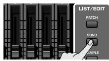
- Press [F3 (Phrase List)].
The MIDI Phrase List screen will appear.
Phrases without the symbol and phrases with the symbol have not been saved.
- Press [F3 (Util Menu)].
The Phrase Utility Menu window will appear.
- Press ▲ / ▼ to choose "Save All," and then press [F8 (Select)].
To cancel, press [F7 (Cancel)].
A confirmation message will appear.
- Press [F7 (OK)] to execute.
If you decide to cancel, press [F8 (EXIT)].

When you execute Save All, the phrases will be written into the same numbers of the phrase list. Phrase names will be assigned automatically.
This section explains how to use the Fantom-G's sequencer to record MIDI.
Phrases and Songs
A “phrase” is a chunk of recorded MIDI data. You can create a song simply by placing phrases in the MIDI tracks of a song.
You can record MIDI either by recording it directly into a MIDI track of a song, or by recording into a phrase.
Recording into a song (p. 218)
In the Song Play screen, select a track and a recording start location, and then begin recording. After recording, the phrase will be attached to the recording start location.
Recording into a phrase (p. 220)
In the MIDI Phrase List screen, select a phrase number and then begin recording. After recording, the phrase will be added to the list.
Two Methods of Recording
There are two ways to record MIDI: realtime recording and step recording. Use the method that's suitable for your needs.
Realtime recording (p. 222)
With this method, your performance on the keyboard and pads, and the controller movements you make, are recorded exactly as you perform them.
Step recording (p. 226)
Step recording allows you to enter notes and rests one by one. This method is suitable when you need to enter notes at a precise timing, such as when recording drums or bass.
NOTE
You can't step-record directly into a song. You can use step recording to record a phrase.
Undo function
This cancels the result of the following edit/recording operations, reverting to the original state.
- Phrase modify (p. 239)
- Microscope (p. 250)
• Phrase recording (realtime/step) (p. 220) -
Track Edit (p. 237)
-
Perform the above editing or recording operation.
- Press [MENU].
- Press [F5 (Undo)].
MEMO
Undo cancels the editing or recording operation that was performed immediately before you executed Undo. If Undo is not possible, the button will be shown in gray and will be disabled.
- A window will ask you to confirm the Undo operation. To execute the Undo, press [F7 (OK)]. If you decide to cancel, press [F8 (CANCEL)].
The result of editing or recording will be cancelled, reverting to the original state.
MEMO
Phrase edit (phrase modify/microscope), phrase recording (realtime/step) and track edit allow you to Undo and Redo.
NOTE
Song recording (realtime recording/audio recording) does not allow for a Redo. Once you carry out an Undo, the recorded result is discarded, and cannot be redone.
MEMO
You can also Undo by holding down [SHIFT] and pressing [EXIT].
Recording into a Song
Recording work-flow
When recording a new song, the work-flow is as follows.
- Select the sound you want to use for recording.
- Erase the song that's in the temporary area.
- Specify the time signature of the song (p. 219).
- Specify the tempo (p. 219).
- Select a MIDI track and the recording-start measure (p. 219).
- Perform realtime recording (p. 222).
- Use song editing to edit the song (p. 232).
- Use phrase editing (p. 238) or microscope editing (p. 250) to edit the phrase.
- Save the song (p. 254).
Selecting a Sound for Recording
Before you record a song, select Studio mode and choose the sound you'll use for recording.
TIP
The Fantom-G's sequencer can record your performance regardless of the sound generator mode (Single, Live, or Studio), but we recommend that you choose Studio mode when you want to record a song. In Studio mode, when you use the Fantom-G's keyboard and pads to record, you'll hear only the sound of the specified MIDI channel, and you can use a different sound for each part (up to sixteen sounds) to play back the recorded song. This means that Studio mode is the appropriate choice when recording or playing back an ensemble performance using multiple instruments such as drums, bass, and piano.
TIP
We recommend that you turn the Keyboard Switch (p. 69) off for all parts. If this is on, multiple parts of your performance will be recorded to a single phrase, which is not what you want when creating a song.
cf.
| Selecting Studio mode | → p. 66 |
| Selecting a Studio Set | → p. 67 |
| Selecting a sound for each part | → p. 68 |
Erasing the Song/Phrases from the Temporary Area (Song Clear)
When you record a song, the performance data is recorded into the temporary area. If you want to record a new song, you'll need to erase the existing performance data from the temporary area before you begin.
NOTE
If you've been editing the currently-opened song, save the song before you continue (p. 254).
- Press [SONG].
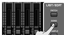
The Song Play screen will appear.
- Press [F7 (Song Util)].
The Song Utility Menu window will appear.
- Use ▲ / ▼ to choose "Song Clear," and then press [F8 (Select)].
To cancel, press [F7 (Cancel)].
A confirmation message will appear.
- Press [F7 (OK)] to execute.
If you decide to cancel, press [F8 (EXIT)].
Specifying the Time Signature (Beat Track)
When you record a new song, start by specifying the time signature. However, if you've just executed the Song Clear operation or turned on the power, the time signature will always be set to 4/4, so you'll need to change this only if the song you're recording uses a different time signature.
-
Press [SONG].
-
Press [F8 (Song Edit)].
The Song Edit screen will appear.
- Press [F7 (Song Util)].
The Song Edit Utility Menu window will appear.
- Press ▲ / ▼ to choose "Beat Track," and press [F8 (Select)].
To cancel, press [F7 (Cancel)].
The Microscope screen for the beat track will appear.
- Move the cursor to "Beat Change," and specify the time signature.
If you want the beat to change in the middle of the song, refer to “Changing the Time Signature during the Song (Beat Track)” (p. 236).
- Press [EXIT] to return to the Song Edit screen.
Specifying the Tempo
Here's how to specify the tempo at which you'll record the song.
- Press [TEMPO].
The Tempo window will appear.
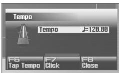
-
Turn the VALUE dial or use [INC] [DEC] to specify the tempo. By holding down [SHIFT] while you turn the VALUE dial, you can adjust the value below the decimal point.
-
If you press [F7 (Click)] to turn it on, the click will sound at the specified tempo. It will turn on/off each time you press the button.
-
You can specify the tempo by pressing [F6 (Tap Tempo)] at the desired interval (Tap Tempo). Press the button at least three times in quarter-note intervals of the desired tempo.
-
When you've finished making settings, press [F8 (Close)].
Selecting a MIDI Track and the Recording-start Measure
Here's how to select the MIDI track on which you'll record, and specify the recording-start measure.
You can record on any of the tracks 1–128 that indicates "MIDI."
TIP
You are free to simultaneously record MIDI data for multiple sound generator parts on the same MIDI track, and you are also free to use multiple MIDI tracks to record MIDI data for a single sound generator part. Initially, you'll probably want to keep things simple by using the MIDI track of the same number as the sound generator part it's playing.
- Press [SONG].
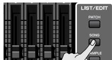
The Song Play screen will appear.
- Turn the VALUE dial or use ▲ / ▼ to select the MIDI track on which you want to record.
Select a track that has the "MIDI" indication.
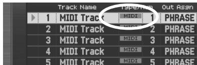
text_image
Track Name 1 MIDI Track 2 MIDI Track 3 MIDI Track 4 MIDI Track 5 MIDI Track MIDI 1 PHRASE MIDI 2 PHRASE MIDI 3 PHRASE MIDI 4 PHRASE MIDI 5 PHRASE
You can change the order in which the tracks are displayed. → “Changing the Track Display Zoom and Display Order (Zoom/Track Order)” (p. 209)
- Use [◀◀] [▶▶] to specify the measure at which you want to start recording.
The recording-start measure is indicated in the "Measure" field at the top of each PLAY screen.
If a phrase already exists at the recording-start location
The existing phrase will be overwritten by your new recording.
If a phrase already exists following the recording-start location
A new phrase will be recorded. You'll be able to record up to the location of the subsequent phrase.
Proceed to Realtime Recording → p. 222
Recording into a Phrase
Recording work-flow
When recording a new phrase, the work-flow is as follows.
- Select the sound you want to use for recording.
- Specify the tempo.
- In the MIDI Phrase List, select the phrase that you want to record (p. 221).
- Perform realtime recording (p. 222) or step recording (p. 226).
- Use phrase editing (p. 238) or microscope editing (p. 250) to edit the phrase.
- Save the phrase (p. 216).
Selecting a Sound for Recording
Before you record a phrase, select Studio mode and choose the sound you'll use for recording.
TIP
The Fantom-G's sequencer can record your performance regardless of the sound generator mode (Single, Live, or Studio), but we recommend that you choose Studio mode when recording.
In Studio mode, when you use the Fantom-G's keyboard and pads to record, you'll hear only the sound of the specified MIDI channel, and you can use a different sound for each part (up to sixteen sounds) to play back the recorded song. This means that Studio mode is the appropriate choice when recording or playing back an ensemble performance using multiple instruments such as drums, bass, and piano.
TIP
We recommend that you turn the Keyboard Switch (p. 69) off for all parts. If this is on, multiple parts of your performance will be recorded to a single phrase, which is not what you want when creating a song.
cf.
Selecting Studio mode → p. 66
Selecting a Studio Set → p. 67
Selecting a sound for each part → p. 68
Specifying the Tempo
Here's how to specify the tempo at which you'll record the phrase.
NOTE
Tempo or time signature settings cannot be stored in a phrase. Phrases always play back at the tempo of the song.
The tempo you're specifying here is a temporary tempo setting for recording.
1. Press [TEMPO].
The Tempo window will appear.
![ROLAND FANTOM G8 - Press [TEMPO]. - 1](/content/2025/01/130804/images/0aa66b55ca389f2fb5bfbb2dbc59813ecca4d1f8b5fbce1cf203d3c999b44a34.jpg)
2. Turn the VALUE dial or use [INC] [DEC] to specify the tempo. By holding down [SHIFT] while you turn the VALUE dial, you can adjust the value below the decimal point.
- If you press [F7 (Click)] to turn it on, the click will sound at the specified tempo. It will turn on/off each time you press the button.
- You can specify the tempo by pressing [F6 (Tap Tempo)] at the desired interval (Tap Tempo). Press the button at least three times in quarter-note intervals of the desired tempo.
3. When you've finished making settings, press [F8 (Close)].
Selecting the Phrase to Record
Access the MIDI Phrase List, and select the phrase that you want to record.
MEMO
Recording operations can also be performed in the Phrase Edit screen (p. 238).
1. Press [SONG].
![ROLAND FANTOM G8 - Press [SONG]. - 1](/content/2025/01/130804/images/a36acad521ed693233a21b924869a90586a26909afd9a4f9a5054ac69e18166e.jpg)
The Song Play screen will appear.
2. Press [F3 (Phrase List)].
The MIDI Phrase List screen will appear.
![ROLAND FANTOM G8 - Press [F3 (Phrase List)]. - 1](/content/2025/01/130804/images/10a34d0f797597259354a188c2effb9f78448da0c24577bb861b9db5fc8f9ae2.jpg)
text_image
MIDI Phrase List MIDI PHRASE LIST 0:0 1:000 Number Phrase Name Files 6/2008 0006 05R&B05 0006 SVP 0007 07R&B07 0007 SVP 0008 08R&B08 0008 SVP 0009 09R&B09 0009 SVP 0010 10HipHp1 0010 SVP 0011 11HipHp2 0011 SVP 0012 12R&B10 0012 SVP 0013 13Pop1 0013 SVP 0014 14HipHp3 0014 SVP 0015 15Pop2 0015 SVP 0016 16R&B11 0016 SVP 0017 01HipHp1 0017 SVP3. Turn the [VALUE] dial or use [INC] [DEC] or ▲ / ▼ to select the phrase that you want to record.
If a phrase already exists in the selected number
The existing phrase will be overwritten by your new recording.
If there is no phrase in the selected number
A new phrase will be recorded.
Proceed to Realtime Recording
→ p. 222
Proceed to Step Recording
→ p. 226
Recording Your Performance Just as You Play It (Realtime Recording)
Realtime recording is the recording method in which your keyboard performance and controller operations are recorded exactly as you perform them. Choose this recording method when you want to capture the nuances of your performance.
Auto Track Function
In the Realtime Rec Standby window, when recording a song, this function will automatically select the same track number as the part you're recording. For example, if the current part of the sound generator is part 3, MIDI track 3 of the song will be selected. If the current part of the sound generator is part 10, MIDI track 10 of the song will be selected. This provides a more intuitive relationship between the parts of the sound generator and the tracks of the song.
The Auto Track function will automatically select the following tracks.
| Current Part | Track |
| Internal 1–16 | MIDI Track 1–16 |
| EXP1 1–16 | MIDI Track 17–32 |
| EXP2 1–16 | MIDI Track 33–48 |
| External 1–16 | MIDI Track 49–64 |
| Audio Track 1–24 (MIXER Screen) | Audio Track 1–24 |
NOTE
If you change the part during recording, the recording track will not change even if the Auto Track function is on.
Turning the Auto Track Function On/Off
By default, the Auto Track function will be on. If you turn the Auto Track function off, the track selected in the Realtime Rec Standby window when recording a song will be the current track of the song.
- Press the [MENU], and then press [F2 (System)].
- Press [F2 (Group/Down)] a number of times to access the Startup group.
- In the "Sequencer Auto Track" field, specify the desired on/off setting.
VALUE
OFF: Auto Track function is off
ON: (default) Auto Track function is on
Basic Procedure for Realtime Recording
- Make sure that you've made the appropriate preparations for recording as described in "Recording into a Song" (p. 218) or "Recording into a Phrase" (p. 220).
- Press [REC].
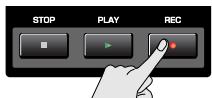
The [REC] indicator will blink, and the Realtime Rec Standby window will appear.
In this window you can set various parameters related to realtime recording.
- Use [CURSOR] to move the cursor to the various parameters, and turn the VALUE dial or use [INC] [DEC] to set them.
cf.
For details on the parameters, refer to “Realtime Rec Standby Parameters” (p. 223).
MEMO
In the Realtime Rec Standby windows, you can press [F6] to switch between recording MIDI and audio.
MEMO
In the Realtime Rec Standby windows, you can select the recording track in the “Recording Track Number” field. If you want to change the recording track, make the desired change in the “Recording Track Number” field.
- When you've finished making settings in the Realtime Rec Standby window, press [PLAY] or [F8 (Start)].
The Realtime Rec Standby window will close, the [REC] indicator will change from blinking to lit, and recording will start.
When recording starts, the Realtime Recording window will appear.
To close this window, press [F8 (Close)] or [PLAY]. To open it again, press [PLAY].
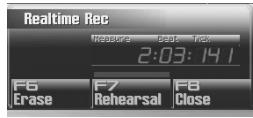
In this window you can perform the following operations.
• Realtime erase (Erase p. 225)
• Rehearsal function (Rehearsal p. 225)
For details on these operations, refer to the corresponding page.
- When you've finished recording, press [STOP].
- A window will ask you to confirm the recording. If you want to keep the recorded result, press [F7 (OK)]. If you decide to cancel, press [F8 (CANCEL)].
MEMO
If you cancel, the recorded phrase will not be pasted into the song, nor will it be added to the phrase list; it will be discarded.
MEMO
You can Undo the result of recording (p. 217).
MEMO
You can change the Input Quantize setting during recording. In the Realtime Rec window that is shown during recording, you can change the following parameters.
- Input Quantize
- Grid Resolution
• Grid Quantize Strength - Shuffle Resolution
- Shuffle Rate
Realtime Rec Standby Parameters
This section explains the Realtime Rec Standby parameters.
Rec Mode
Selects how recording is to take place.
Value
MIX: Mix-recording will be carried out. Normally, you will record using this method. If a performance has already been recorded on the recording-destination phrase, your newly recorded performance will be added to the existing performance without erasing it. By using this in conjunction with Loop-recording, you can record repeatedly over a specified area without erasing the previously recorded performance. For example, this is a convenient way to record a drum performance one instrument at a time; bass drum → snare drum → hi-hat, etc.
REPLACE: Replace-recording will be carried out. If a performance has already been recorded on the recording-destination phrase, it will be erased as you record your new performance. Use this when you want to re-record.
Count In
Selects how recording is to begin.
Value
OFF: Recording will begin immediately when you press [PLAY].
1 MEAS: When you press [PLAY], a count ( playback) will begin one measure before the recording-start location, and recording will begin when you reach the recording-start location.
2 MEAS: When you press [PLAY], a count ( playback) will begin two measures before the recording-start location, and recording will begin when you reach the recording-start location.
WAIT NOTE: As an alternative to pressing [PLAY], you can play the keyboard, strike a pad, or press the Hold pedal to start recording.
Tempo Rec Switch
Specifies whether tempo changes will be recorded (ON) or not recorded (OFF).
If you want the tempo to change during the song, you can record those tempo changes in the tempo track. If tempo
changes have already been recorded, they will be overwritten by your new tempo changes.
Value: OFF, ON
Loop Switch
Specifies whether loop recording will be on (ON) or off (OFF). The loop region is from the Rec Start Point to the Rec End Point.
Value: OFF, ON
Rec Start Point
Indicates the measure, beat, and tick at which recording will start.
Rec End Switch
Specifies whether a recording end point will be assigned (ON) or not assigned (OFF).
Rec End Point
Specifies the measure, beat, and tick at which recording will end.
This setting is ignored if Rec End Switch is "OFF."
Rec Length
Specifies the length of the recording region in measures, beats, and ticks. The Rec Length setting and Rec End Point setting are linked.
Input Quantize
The Quantize function automatically corrects inaccuracies in the timing of your keyboard or pad performance, aligning the notes to accurate timing intervals. During realtime recording, you can quantize while you record.
Specify whether to quantize while recording.
Value
OFF: Quantize will not be applied while recording.
GRID: Grid Quantize will be applied while recording. Use this when you want the timing to be accurate, such as when recording drums or bass.
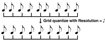
text_image
Grid quantize with Resolution = ♪SHUFFLE: Shuffle Quantize will be applied while recording. Use this when you want to give the rhythm a "shuffle" or "swing" character.
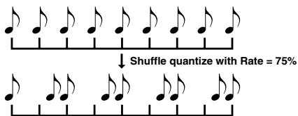
text_image
↓ Shuffle quantize with Rate = 75%Grid Resolution
Make this setting when you are using Grid Quantize. Specify the quantization interval in terms of a note value. Select the shortest note value that will occur in the range to which Grid Quantize will be applied.
Value: ♣, ♣₃, ♣, ♣₃, ♣, ♣₃, ♣
Grid Quantize Strength
Make this setting when you are using Grid Quantize. It specifies the degree to which notes will be adjusted toward the timing intervals specified by the Grid Resolution parameter. With a setting of “100%,” the notes will be corrected precisely to the timing of the Grid Resolution parameter. As you lower this setting, the note timing will be corrected to a lesser extent, and with a setting of “0%” the timing will not be adjusted at all.
Value: 0–100%
Shuffle Resolution
When you are using Shuffle Quantize, make this setting to specify the note value used for quantization.
Value: ♪, ♪
Shuffle Rate
Make this setting when using Shuffle Quantize. It specifies the degree to which the backbeat will be separated from the downbeat specified by the Shuffle Resolution parameter. With a setting of “50%,” the backbeat will be exactly between adjacent downbeats. With a setting of “0%,” the backbeat will be moved to the same timing as the preceding downbeat. With a setting of “100%,” the backbeat will be moved to the same timing as the following downbeat.
Value: 0–100%
Selecting the Sequencer Data that will Be Recorded (Recording Select)
When you use realtime recording, all of your sequencer data will normally be recorded. If you want to avoid recording a specific type of data, you can turn its Recording Select setting "OFF."
- Press [REC].
- Press [F7 (Rec Select)].
The Recording Select window appears.
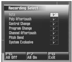
text_image
Recording Select Note Poly Aftertouch Control Change Program Change Channel Aftertouch Pitch Bend System Exclusive F6 All Off F7 All On F8 Exit- Use ▲ or ▼ to select the sequencer data (MIDI messages) that will be recorded.
| Note: | Note messages. These MIDI messages represent notes. |
| Poly Aftertouch: | Polyphonic aftertouch. These MIDI messages apply aftertouch to individual keys. |
| Control Change: | Control change messages. These MIDI messages apply various effects such as modulation or expression. |
| Program Change: | Program change messages. These MIDI messages select sounds. |
| Channel Aftertouch: | Channel aftertouch messages. These MIDI messages apply aftertouch to an entire MIDI channel. |
| Pitch Bend: | Pitch bend messages. These MIDI messages change the pitch. |
| System Exclusive: | System exclusive messages. These MIDI messages are used to make settings unique to the Fantom-G, such as sound parameters. |
- Turn the VALUE dial or press [INC] [DEC] to add a check mark.
The message will be recorded if you assign a check mark (√), and will not be recorded if you remove the check mark. If you press [F6 (All Off)], no sequencer data will be recorded. If you press [F7 (All On)], all of the sequencer data will be recorded.
- Press [F8 (Close)] to close the Recording Select window.
Erasing Unwanted Data While You Record (Realtime Erase)
Realtime Erase is a function that erases unwanted data during realtime recording. This is particularly convenient during loop recording, since it lets you erase data without stopping recording.
NOTE
Realtime Erase can be executed only if the Recording Mode is set to "MIX."
1. Begin realtime recording (p. 222).
The Realtime Recording window appears.
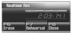
2. Press [F6 (Erase)].
The Realtime Erase window appears.
![ROLAND FANTOM G8 - Press [F6 (Erase)]. - 1](/content/2025/01/130804/images/51c9306af95496f14aa3322639e04ae18abcf4a02f842744be8da5702128305f.jpg)
text_image
Realtime Erase Lowest Note ----(----) Highest Note ----(----) Press keys. F7 Erase All F8 Close 3:02:32 13. Erase unwanted data.
To erase all data, press [F7 (Erase All)]. Data will be erased for as long as you hold down the button.
To erase notes of a specific key, hold down that key. Data for that note will be erased for as long as you hold down that key. To erase notes of a specific key range, hold down the top and bottom keys of that range. Data for that range will be erased for as long as you hold down those keys.
4. Press [F8 (Close)] to close the Realtime Erase window.
You will return to the normal recording state.
Auditioning Sounds or Phrases While Recording (Rehearsal Function)
The Rehearsal function lets you temporarily suspend recording during realtime recording. This is convenient when you want to practice the phrase that you will record next.
1. Begin realtime recording (p. 222).
The Realtime Recording window appears.
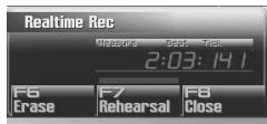
2. Press [F7 (Rehearsal)] or [REC].
The [REC] indicator will blink, indicating that you are in rehearsal mode. In this state, nothing will be recorded when you play the keyboard.
3. To return to record mode, press [F7 (Rehearsal)] or [REC] once again.
Inputting Data One Step at a Time (Step Recording)
Step recording lets you record notes and rests one at a time, just as though you were writing them onto a musical staff.
NOTE
You can't step-record directly into a song. You can use step recording to record a phrase.
Entering Notes and Rests
-
Make sure that you've made the appropriate preparations for recording as described in "Recording into a Phrase" (p. 220).
-
Press [F8 (Phrase Edit)] in the MIDI Phrase List.
The Phrase Edit screen will appear.
- Press [F5 (Step Rec)]
The [REC] indicator will blink, and the Step Recording Standby window will appear.
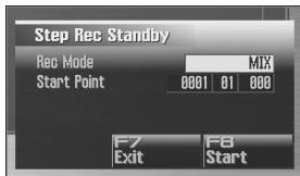
text_image
Step Rec Standby Rec Mode MIX Start Point 0001 01 000 F7 F8 Exit StartMEMO
You can also access the Step Recording Standby window by holding down [SHIFT] and pressing [REC] in the MIDI Phrase List.
- Make settings for step recording. Use [CURSOR] to move the cursor to the desired parameter, and turn the VALUE dial or use [INC] [DEC] to set the parameter.
• Rec Mode (Recording Mode)
Selects how recording is to take place.
Value
MIX: Mix-recording will be carried out. Normally, you will record using this method. If a performance has already been recorded on the recording-destination phrase, your newly recorded performance will be added to the existing performance without erasing it.
REPLACE: Replace-recording will be carried out. If a performance has already been recorded on the recording-destination phrase, it will be erased as you record your new performance. Use this when you want to re-record.
- Start Point
Specifies the location (measure-beat-tick) at which recording will begin.
- Press [F8 (Start)] or [PLAY].
The [REC] indicator will light, and the Step Rec (Note) screen appears.
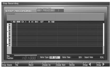
text_image
Step Recording STEP RECOORING BOOT(PHASE:8001) 1:02:000 Ch 1 E 4(64) 127 8:192 Reo Position 1:0 1:000 Note Type M (A) Gate Time 80% Input Velo REAL F1 Step Back F2 Tie F3 Rest F4 Zoom In F5 Zoom Out F6 Untie F7 Step F8 Step- Specify the note that you want to input. Use ◀ or ▶ to select the desired parameter.
- Note Type
Specifies the length of the notes that you want to input, in terms of a note value. The length of the note value indicates the length from one note-on to the next note-on.
Value: ♪ , ♪3 , ♪ , ♪ , ♪3 , ♪ , ♪ , ♪3 , ♪ , ♪ , ♪3 ,
$$ \text { ♣. }, \text { ♣, } \text { ♂3 }, \text { ♣. }, \text { ♂, } \text { ♂, } \text { ♂ } $$
- Gate Time
Specifies the proportion of the gate time relative to the Note Type. The gate time is the length between note-on and note-off. Specifies a lower value if you want the notes to be played staccato, or a higher value if you want the notes to be played tenuto, or as a slur. Normally, you will set this to about “80%.”
Value: 1–100%
- Input Velo
Specifies the strength with which the note will be played. If you want this to be the strength with which you actually pressed a key or a pad, select "REAL." Otherwise, use settings of p (piano)=60, mf (mezzo forte)=90, or f (forte)=120 as general guidelines.
Value: REAL, 1–127
-
Turn the VALUE dial or press [INC] [DEC] to make the setting.
-
Press [F7 ( )] or [F8 ( )] to move to the desired input location, and press a note on the keyboard or a pad.
When you press a key or a pad, the note messages are displayed as a bar. The velocities are displayed as a bar graph.
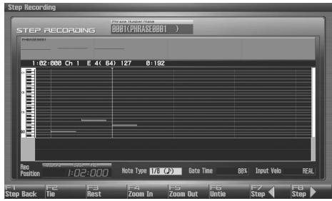
text_image
STEP RECORDING STEP RECORDING (0000000000000000000000000000000000000000000000000000000000000000000000000000000000000 1:02:000 Ch 1 E 4( 64) 127 8:192 Step Back F2 F3 F4 F5 F6 F7 F8 Tie Rest Zoom In Zoom Out Untic Step Step Note Type (M /s) Data Time BB1 Input Velo PEXLYou can use the function buttons ([F1] [F2] [F3] [F4] [F5] [F6]) to perform the following operations.
- Step Back
Cancel the previously input note.
- Tie
Extend the length of the previously input note by the current setting.
- Rest
Inputs a rest. First set the Note Type parameter to a length that is the same as the rest you want to input.
- Zoom In
Narrow the range of keys shown in the display. Use this when you want to view certain notes at greater magnification.
- Zoom Out
Expand the range of notes shown in the display. Use this when you want to see which notes have been input.
- Untie
Removes the most recently input tie.
9. Repeat the above steps to continue inputting.
TIP
The previous value of each parameter is remembered. This means that if you want to use the same settings as the previously input note, there is no need to change the settings. Once you have set the Gate Time parameter and Input Velocity parameter, it is not normally necessary to change them, so all you have to do is set the Note Type parameter and specify the pitch (keyboard, pad) of each note.
10. When you are finished step recording, press [STOP].
The [REC] indicator will go dark.
MEMO
You can Undo the result of recording (p. 217).
Inputting a Chord
Press the chord. The cursor will move to the next step when you release all keys or pads.
Moving the input location
- Pressing [F8 (→)] will move the input location forward by the current Note Type value.
- Pressing [F7 (←)] will move the input location backward by the current Note Type value.
- Hold down [SHIFT] and press [F8 (→)] will advance the input location by one measure.
- Hold down [SHIFT] and press [F7 ( )] will return the input location by one measure.
Moving the display region
Pressing ▲ or ▼ will move the displayed region of notes upward or downward.
The Relation between Note Value Length and Gate Time
The relation between the length of the note value and the gate time is shown below. Since the Fantom-G's sequencer uses a TPQN (Ticks Per Quarter Note; i.e., resolution) of 480, a quarter note gate time is 480 ticks.
| Note | Gate time |
| 30 | |
| 40 | |
| 45 | |
| 60 | |
| 80 | |
| 90 | |
| 120 | |
| 160 | |
| 180 | |
| 240 | |
| 320 | |
| 360 | |
| 480 | |
| 640 | |
| 720 | |
| 960 | |
| 1920 | |
| 3840 |
TIP
The gate time that is recorded in step recording will be the original gate time value multiplied by the value of the Gate Time parameter. For example, if the Gate Time parameter is set to “80%,” inputting a quarter note will mean that the gate time is 480 × 0.8 = 384 .
This section explains how to use the Fantom-G's sequencer to record audio.
TIP
About the audio recording time
The Fantom-G has 32 MB of built-in memory, which allows you to record approximately six minutes of mono audio or approximately 3 minutes of stereo audio. If you want to record for longer than this, you'll need to install commercially available memory (DIMM) (p. 312, p. 314).
Samples and Songs
A piece of recorded audio data is called a "sample." You can create a song simply by placing samples in an audio track of a song.
You can record audio either by recording directly into an audio track of a song, or by recording only samples (sampling), or by importing WAV or AIFF files from your computer.
Recording into a song (p. 228)
From the Song Play screen, select a track and a record-start location, and then record.
After recording, the sample will be assigned to the record-start location of the track.
Sampling (p. 258)
You can use the Sampling function to record audio. The samples you record will be added to the sample list. You can create a song by freely placing these samples in an audio track of the song.
Importing from your computer (p. 287)
You can import WAV or AIFF files from your computer. The imported WAV or AIFF files will be added to the sample list as samples. You can create a song by freely placing these samples in an audio track of the song.
Recording into a Song
When recording audio into a song, the work-flow is as follows.
- Select an audio track and the recording-start location (p. 229).
- Perform audio recording (p. 230).
- Use song editing (p. 232) to edit the song.
- Edit the samples (p. 263).
- Save the song (p. 254).
Selecting an Audio Track and the Recording-start Measure
Here's how to select an audio track for recording, and specify the recording-start measure.
You can record on any of the tracks 1–24 that are marked "AUDIO."
1. Press [SONG].
![ROLAND FANTOM G8 - Press [SONG]. - 1](/content/2025/01/130804/images/99fae41cb5511408d531eeaf14a0d40a4a4e9bfc5805dbd8b33876412fcd5248.jpg)
The Song Play screen will appear.
2. Turn the VALUE dial or use ▲ / ▼ to select the audio track on which you want to record.
Select a track that's marked "AUDIO."
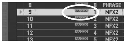
text_image
8 9 AUDIO: 1 AUDIO: 2 AUDIO: 3 AUDIO: 4 AUDIO: 5 PHRASE MFX2 MFX2 MFX2 MFX2 MEX2cf.
You can change the order in which the tracks are displayed. → “Changing the Track Display Zoom and Display Order (Zoom/Track Order)” (p. 209)
3. Use [◀◀] [▶▶] to specify the measure at which you'll start recording.
The recording-start measure is shown in the "Measure" field located at the top of each PLAY screen.
If the track already contains a sample
Each audio track always plays only one sample per track. If samples overlap in a track, the latter sample will be heard.
4. Press the [REC] button to enter record-standby mode.
![ROLAND FANTOM G8 - Press the [REC] button to enter record-standby mode. - 1](/content/2025/01/130804/images/83c9b303f91ffc51ecacb254de2f87f58f832a94a996d27ef075085eb33924e5.jpg)
Proceed to Audio Recording
→ p. 230
Audio Recording
Here's how to record audio input from an audio device, mic, or CD onto an audio track.
Basic Procedure for Audio Recording
-
Make sure that you've completed the preparations for recording as described in "Selecting an Audio Track and the Recording-start Measure" (p. 229).
-
Press [REC].
* This step is the same as step 4 on “Selecting an Audio Track and the Recording-start Measure” (p. 229).
The [REC] indicator will blink, and the Audio Rec Standby window will appear.
In this window you can set various parameters related to audio recording.
MEMO
Pressing [F7 (Inp Setting)] will access the Input Setting screen (p. 258), where you can make settings for the external input.
MEMO
You can apply effects such as equalizer or compressor to the audio input. Press [F7 (Inp Setting)] to access the INPUT EFFECT screen, where you can make effect settings. For details on the parameters that you can set, refer to “Input Effect Parameters” (p. 186).
MEMO
In the Realtime Rec Standby/Audio Rec Standby windows, you can press [F6] to switch between recording MIDI and audio.
MEMO
In the Realtime Rec Standby/Audio Rec Standby windows, you can select the recording track in the "Recording Track Number" field. If you want to change the recording track, make the desired change in the "Recording Track Number" field.
- Use [CURSOR] to move the cursor to the desired parameter, and turn the VALUE dial or use [INC] [DEC] to set the value.
cf.
For details on each parameter, refer to “Audio Rec Standby Parameters” (p. 231).
- If you're recording from the AUDIO INPUT, turn the rear panel LEVEL knob (p. 24) to adjust the input level from your external source.
* This adjustment is not needed if you're using DIGITAL IN.
* If the volume of the external input is too high, the PEAK indicator will light. In this case, turn down the LEVEL knob until the PEAK indicator no longer lights.
* If the recording level is too high, the level meter in the screen will indicate "CLIP."
* If an external device is connected to the DIGITAL AUDIO IN connector, and you disconnect the cable or power-off your external device, noise may subsequently be heard in the input from DIGITAL AUDIO IN. If this occurs, re-connect the external device correctly, or turn off the Fantom-G's [MIX IN] switch.
- Press [PLAY] or [F8 (Start)].
The Audio Rec Standby window will close, the [REC] indicator will change from blinking to lit, and recording will start.
When recording starts, the Realtime Recording window will appear.
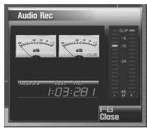
text_image
Audio Rec dB dB CLIP -5 -12 -24 -48 1:03:28.1 F8 Close- When you're finished recording, press [STOP].
- A window will ask you to confirm the recording. If you want to keep the recorded result, press [F7 (OK)]. If you decide to cancel, press [F8 (CANCEL)].
MEMO
If you cancel, the recorded sample will not be pasted into the song, nor will it be added to the sample list; it will be discarded.
The [REC] indicator will go dark.
The sample you recorded will be placed in the audio track.
MEMO
You can Undo the result of recording (p. 217).
MEMO
The recorded sample will be lost when you turn off the power.
If you want to keep the sample, you must save it (p. 274).
Audio Rec Standby Parameters
This section explains the Realtime Rec Standby parameters.
Audio Rec Mode (Audio recording mode)
Specifies how recording will occur.
Value
SOLO: While playing the internal sound generator as usual, record only the sound from the external input.
* Effects other than the Input Effect cannot be applied to the external input sound.
SOLO WITH FX: While playing the internal sound generator, record only the sound from the external input. While doing so, you can apply an effect to the external input sound.
* If the recording mode is "SOLO WITH FX," you cannot apply MFX (multi-effect) to the sound of the internal sound generator.
RE-SAMPLING: Record the sound of the internal sound generator (including the audio tracks). The external input will not be heard.
* The volume of resampled phrases may be less than the original volume of the phrase. As needed, use Normalize (p. 270) to raise the volume.
Input Select
Selects the input source.
Value
DIGITAL IN: DIGITAL AUDIO IN jack
LINE IN L/R: INPUT jacks L/R (stereo)
LINE IN L: INPUT jack L (mono)
MIC/GUITAR: MIC/GUITAR jack
USB AUDIO: USB connector
Audio Rec Channel (Audio recording channel)
When recording an audio track, selects whether the recorded track will be stereo or mono.
Value
MONO: Recording in mono.
STEREO: Recording in stereo.
Count In
Selects how recording will begin.
Value
OFF: Recording will begin as soon as you press [PLAY].
1 MEAS: When you press [PLAY], there will be a count starting one measure before the recording-start location, and recording will begin at the recording-start location.
2 MEAS: When you press [PLAY], there will be a count starting two measures before the recording-start location, and recording will begin at the recording-start location.
Rec Start Point (Recording start point)
Indicates the measure, beat, and tick at which recording will start.
Rec End Switch (Recording end switch)
Selects whether a recording-end point will be specified (ON) or not (OFF).
Rec End Point (Recording end point)
Specifies the measure, beat, and tick at which recording will end.
This setting will have no effect if the Rec End Switch is "OFF."
Rec Length (Recording length)
Specifies the length of the recorded region in measures, beats, and ticks. This setting is linked with the Rec End Point settings.
This section explains how to edit songs.
Three Ways to Edit
Editing a song (p. 232)
In the Song Play screen and Song Edit screen you can edit the entire song. Here you can make settings for each track, and rearrange the phrases and samples. The tracks of a song do not contain the samples or phrases themselves, but merely hold information telling “at this point, play sample (or phrase) number so-and-so.”
Editing a phrase (p. 238)
You can edit the individual phrases that are assigned to the tracks. Use the Phrase Edit screen to edit phrases.
Editing a sample (p. 263)
You can edit the individual samples that are assigned to the tracks. Use the Sample Edit screen to edit samples.
Editing a Song (Song Edit)
Opening the Song Edit Screen
To edit a song, access the Song Edit screen.
1. Press [SONG].
![ROLAND FANTOM G8 - Press [SONG]. - 1](/content/2025/01/130804/images/3e6ef954ac11736eab546514c8184e91ec1a63f6e1776ea5d526f2c0fec279c4.jpg)
The Song Play screen will appear.
2. Press [F8 (Song Edit)].
The Song Edit screen will appear.
![ROLAND FANTOM G8 - Press [F8 (Song Edit)]. - 1](/content/2025/01/130804/images/55d255cfe98fb338139de294b53b67c3f7611eff85af0aa1e7f74ffee84d5f9b.jpg)
You can also access the Song Edit screen by pressing [SONG] twice in succession.
![ROLAND FANTOM G8 - Press [F8 (Song Edit)]. - 2](/content/2025/01/130804/images/f25c785bb49457f00b1359e7ce6ed1e615ff5e24c1076289f1da6fe5c83bf279.jpg)
text_image
Song Edit 001-INT SONG 4/4 #120.00 0006 ON OFF Track Name Type/No 1 2 3 4 5 6 7 8 1 #0111111 1 2 #0111111 2 3 #0111111 3 4 #0111111 4 5 #0111111 5 6 #0111111 6 7 #0111111 7 8 #0111111 8 9 #0.5mp0001 9 10 C50000 2 11 C50000 3 12 C50000 4 13 C50000 5 14 C50000 6 15 C50000 7 16 C50000 8 Interlatch Properties F1 Insert F2 Delete F3 Copy F4 Edit F5 Loop F6 F7 Marker F8 F9 F10 Song Util F11 Song PlayF-keys operations in the Song Edit screen
| F-key | Explanation | Page | |
| F1 Insert | Inserts a sample/phrase at the specified location. | p. 233 | |
| F2 Delete | Deletes the selected sample/phrase from the track. | p. 234 | |
| F3 Copy | Copies the selected sample/phrase. | p. 234 | |
| F4 Edit | If a sample is selected: Opens the Sample Edit screen. | p. 266 | |
| If a phrase is selected: Opens the Phrase Edit screen. | p. 238 | ||
| F5 Loop | Opens the Loop window, where you can specify the loop region. | p. 208 | |
| F6 Marker | Opens the Marker window, where you can assign markers. | p. 208 | |
| F7 Song Util | Zoom/ Track Order | Zooms the track display, or changes the displayed order of the tracks. | p. 209 |
| Song Clear | Erases the song. | p. 235 | |
| Track Clear | Erases the track. | p. 235 | |
| Track Name | Assigns a name to the track. | p. 235 | |
| Track Edit Insert | Inserting a Blank Measure | p. 237 | |
| Track Edit Delete | Deleting Unwanted Measures | p. 237 | |
| Track Edit Copy | Copying Measures | p. 237 | |
| Tempo Track | Changes the tempo. | p. 235 | |
| Beat Track | Changes the time signature. | p. 236 | |
| Save As SMF | Save As an SMF File | p. 256 | |
| F8 Song Edit | Opens the Song Play screen. | p. 205 | |
SHIFT + F-keys operations in the Song Edit screen
| F-key | Explanation | Page |
| SHIFT + F1 Trk Edit Ins | Inserting a Blank Measure | p. 237 |
| SHIFT + F2 Trk Edit Del | Deleting Unwanted Measures | p. 237 |
| SHIFT +F3 Trk Edit Copy | Copying Measures | p. 237 |
| SHIFT +F8 Zoom | Zooms the track display, or changes the displayed order of the tracks. | p. 209 |
Moving a Sample/Phrase (Move)
Here's how to move the currently selected sample/phrase to another track or location.
-
Access the Song Edit screen (p. 232).
-
Use [CURSOR] to select the sample/phrase that you want to move.
-
Press [SHIFT].
The cursor will change to the following shape.
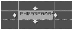
- Continuing to hold down [SHIFT], press ▲ or ▼.
The sample/phrase will move to a different track.
MEMO
Samples can be moved to audio tracks, and phrases can be moved to MIDI tracks.
- Continuing to hold down [SHIFT], use the following buttons to move the sample/phrase.
[INC] [DEC] Move the sample/phrase in steps of one tick.

Move the sample/phrase in steps of one measure.
VALUE dial Move the sample/phrase in steps of a 16th note (120 ticks).
MEMO
If you're using a USB mouse, you can move a phrase by using the mouse to drag it (hold down the left mouse button and move it).
Inserting a Sample/Phrase at a Specified Location (Insert)
Here's how to insert a sample/phrase at the location you specify. Samples will automatically be selected for an audio track, and phrases will automatically be selected for a MIDI track.
-
Access the Song Edit screen (p. 232).
-
Use ▲ / ▼ to select the track into which you want to insert a sample/phrase.
-
Specify the location at which you want to insert a sample/phrase.
The buttons will operate as follows.
[◀] Move the current location to the beginning of the song.
[INC] [DEC] Move the current location in steps of one tick.
[◀◀] [▶▶] Move the current location in steps of one measure.
VALUE dial Move the current location in steps of one beat.
- Press [F1 (Insert)].
For a MIDI track
The MIDI Phrase Select screen will appear.
For an audio track
The Sample Select screen will appear.
- Select the sample/phrase that you want to insert, and press [F8 (Select)].
The sample/phrase will be inserted at the specified location.
Deleting a Sample/Phrase from a Track (Delete)
Here's how to delete the selected sample/phrase from the track.
- Access the Song Edit screen (p. 232).
- Use [CURSOR] to select the sample/phrase that you want to delete.
- Press [F2 (Delete)].
The selected sample/phrase will be deleted from the track.
MEMO
This operation simply deletes the sample/phrase from the track; the actual data will remain in the sample/phrase list.
Copying a Sample/Phrase (Copy)
Here's how to copy the currently selected sample/phrase.
- Access the Song Edit screen (p. 232).
- Use [CURSOR] to select the sample/phrase that you want to copy.
- Press [F3 (Copy)].
The currently selected sample/phrase will be copied immediately following itself.
MEMO
If you're using a USB mouse, you can copy a sample/phrase by holding down [SHIFT] and clicking the sample/phrase with the mouse.
Editing a Sample/Phrase (Edit)
Here's how to edit the currently selected sample/phrase.
If a sample is selected: The Sample Edit window will appear.
If a phrase is selected: The Phrase Edit window will appear.
- Access the Song Edit screen (p. 232).
- Use [CURSOR] to select the sample/phrase that you want to edit.
- Press [F4 (Edit)].
For a sample
The Sample Edit screen will appear → p. 266
For a phrase
The Phrase Edit screen will appear → p. 238
Song Utility (Song Util)
Changing the Track Display Zoom and Display Order (Zoom/Track Order)
cf.
"Changing the Track Display Zoom and Display Order (Zoom/Track Order)" (p. 209)
Erasing the Currently-open Song (Song Clear)
Here's how to erase the song that's currently open in the Song Play screen. Use this operation when you want to record a new song. The song file itself that's saved in the project will not be deleted.
NOTE
If you've edited the currently-open song, save it before you continue (p. 254).
-
Access the Song Edit screen (p. 232).
-
Press [F7 (Song Util)].
The Song Edit Utility Menu window will appear.
- Use ▲ / ▼ to choose "Song Clear," and press [F8 (Select)].
To cancel, press [F7 (Cancel)]. A confirmation message will appear.
- Press [F7 (OK)] to execute.
If you decide to cancel, press [F8 (EXIT)].
Clearing a Track (Track Clear)
Here's how to erase the selected track. The track name and track setup data will also return to the default settings.
-
Access the Song Edit screen (p. 232).
-
Use ▲ / ▼ to select the track that you want to clear.
-
Press [F7 (Song Util)].
The Song Edit Utility Menu window will appear.
- Use ▲ / ▼ to choose "Track Clear," and press [F8 (Select)].
To cancel, press [F7 (Cancel)]. A confirmation message will appear.
- Press [F7 (OK)] to execute.
If you decide to cancel, press [F8 (EXIT)].
Naming a Track (Track Name)
You can assign a name of a track.
- Access the Song Edit screen (p. 232).
- Use ▲ / ▼ to select the track that you want to rename.
- Press [F7 (Song Util)].
The Song Edit Utility Menu window will appear. -
Use ▲ / ▼ to choose "Track Name," and press [F8 (Select)]. To cancel, press [F7 (Cancel)].
-
Assign the name.
cf.
For details on assigning a name, refer to “Assigning a Name” (p. 42).
- Press [F8 (Write)] to finalize the name.
Changing the Tempo during the Song (Tempo Track)
If you want the tempo to change during the song, insert new tempo change data into the tempo track. Following the location at which you insert the tempo change, the song will play at that tempo. However, if you want to create a gradual tempo change such as a ritardando or accelerando, it's more convenient to use Tempo Recording (p. 223).
TIP
If you want to make the overall tempo of the song faster or slower, you can adjust the playback tempo in the various PLAY screens.
- Access the Song Edit screen (p. 232).
- Press [F7 (Song Util)].
The Song Edit Utility Menu window will appear. - Use ▲ / ▼ to choose "Tempo Track," and press [F8 (Select)]. To cancel, press [F7 (Cancel)].
- Press [F1 (Create)].
The Create Event window will appear. In the window, "Tempo Change" will be selected. - Press [F8 (Execute)].
The Create Position window will appear. - Use ◀ / ▶ to move the cursor to "Measure (Meas)," "Beat," and "Tick."
- Turn the VALUE dial or use [INC] [DEC] to specify the location at which the tempo change will be inserted.
- Press [F8 (Execute)] to insert the tempo change.
- The inserted tempo change will have the default tempo value, so adjust the value as desired.
MEMO
For details on editing the tempo track, refer to “Editing Individual Items of Sequencer Data (Microscope)” (p. 250).
However, the only data that can be handled by the tempo track is as described in “Tempo Change” (p. 236).
Data handled by the tempo track
The tempo track records tempo data for the song.
Tempo Change
This data specifies the tempo. The song will play according to the value of these tempo changes.
The value shown in “ ♪ =^** ” is the tempo at which the song will actually play (the playback tempo), and can be adjusted in the PLAY screen of each mode.
If the tempo change value differs from the playback tempo, this means that the playback tempo has been changed temporarily. In other words, the tempo change values have not been rewritten, so this setting will be lost if you switch to a different song or turn off the power. If you want the song to play at this tempo the next time as well, you must re-save the song. This will rewrite the tempo change values to match the actual playback tempo.
Changing the Time Signature during the Song (Beat Track)
If you want the time signature to change during the song, insert new beat change data into the beat track. Following the location at which you insert the beat change, the song will play at that time signature.
NOTE
You can't change the time signature in the middle of a measure. The time signature can be changed only at the beginning of a measure.
- Access the Song Edit screen (p. 232).
- Press [F7 (Song Util)].
The Song Edit Utility Menu window will appear. - Use ▲ / ▼ to choose "Beat Track," and press [F8 (Select)]. To cancel, press [F7 (Cancel)].
- Press [F1 (Create)].
The Create Event window will appear. In the window, "Beat Change" will be selected. - Press [F8 (Execute)].
The Create Position window will appear. - Use ◀ / ▶ to move the cursor to “Measure (Meas).”
- Turn the VALUE dial or use [INC] [DEC] to specify the location at which the beat change will be inserted.
- Press [F8 (Execute)] to insert the beat change.
- The inserted beat change will have the default value, so adjust the value as desired.
MEMO
For details on editing the beat track, refer to “Editing Individual Items of Sequencer Data (Microscope)” (p. 250). However, the only data that can be handled by the beat track is as described on “Beat Change” (p. 236).
Data handled by the beat track
The beat track records time signature data.
Beat Change
This data specifies the time signature (Beat).
Track Edit Function
In the Song Play/Song Edit screen you can perform Track operations such as Insert (Inserting a Blank Measure), Delete (Deleting Unwanted Measures), or Copy (Copying Measures).
NOTE
The Track Edit functions do not edit the phrases or samples themselves. For example, if you have assigned a ten-measure long phrase to measure 1, and then use the track edit function "Track Edit Delete" (Deleting Unwanted Measures) to delete measures 2–3, no content within the phrase will be deleted. If you want to delete material from within the phrase, use a Phrase Modify function (p. 239) to edit the phrase.
- In the Song Play/Song Edit screen, press [F7 (Song Util)].
- From the menu that appears, select one of the following items and press [F8 (Select)].
| Menu | Explanation |
| Track Edit Insert | Inserting a Blank Measure |
| Track Edit Delete | Deleting Unwanted Measures |
| Track Edit Copy | Copying Measures |
cf.
Details about the windows for each of the Track Edit functions are explained in the section on each function.
MEMO
You can also perform track edit functions in the Song Play/ Song Edit screen by holding down [SHIFT] and pressing [F1]-[F3].
- Set the parameters for each function. Use the cursor buttons to move the cursor to the desired parameter, and turn the VALUE dial or use [INC]/[DEC] to set the value.
- Press [F8 (Execute)].
A confirmation screen will appear.
- Press [F7 (OK)] to execute.
MEMO
You can undo the result of the editing operation by pressing [MENU]→[F5 (Undo)].
Inserting Blank Measures into a Track (Track Edit Insert)
This function inserts blank measures into a specified phrase position.
Source Track
Select the track that you want to edit. If you want to edit all tracks, select "ALL."
Measure, For (Edit Range)
Specifies the measure location at which the blank measures are to be inserted, and the number of blank measures to be inserted.
Beat (Time Signature)
Specify the time signature.
Deleting Unwanted Measures from a Track (Track Edit Delete)
This function deletes a specified area of sequencer data, and moves the subsequent data to fill the gap. As a result, the measure length will be shortened by the number of deleted measures.
Source Track
Select the track that you want to edit. If you want to edit all tracks, select "ALL."
Measure, For (Edit Range)
Specifies the range of measures that are to be deleted. If you set "For" to "ALL," all measures will be specified.
Copying Measures of a Track (Track Edit Copy)
You can copy measures of the specified region in a track.
NOTE
If the region to copy does not include the beginning of a phrase or sample, that phrase or sample will not be copied.
Source Track
Select the track that you want to edit. If you want to edit all tracks, select "ALL."
Src Measure, For (Edit Range)
Specifies the range of copy-source measures. If you set "For" to "ALL," all measures will be specified.
Dst Measure (Destination Measure)
Specifies the copy-destination measure.
If you want the copy destination to be right after the last measure of a phrase, set this parameter to "END."
Copy Times
Specifies the number of times that the data will be copied to the copy destination.
Editing a Phrase (Phrase Edit)
NOTE
If a certain phrase is used by multiple songs in a project, editing that phrase will affect the content of all these songs. If you will be editing a phrase that is used by other songs, it's a good idea to duplicate the phrase beforehand.
→ “Duplicating a Phrase (Duplicate)” (p. 215)
Opening the Phrase Edit Screen
To edit a phrase, access the Phrase Edit screen.
The Phrase Edit screen can be opened from the MIDI Phrase List or from the Song Edit screen.
From MIDI Phrase List
- Press [SONG].
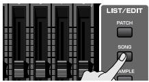
The Song Play screen will appear.
- Press [F3 (Phrase List)].
The MIDI Phrase List screen will appear.
-
Turn the VALUE dial or use [INC] [DEC] or ▲ / ▼ to select the phrase that you want to edit.
-
Press [F8 (Phrase Edit)].
The Phrase Edit screen will appear.
From Song Edit
- Press [SONG].
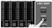
The Song Play screen will appear.
- Press [F8 (Song Edit)].
The Song Edit screen will appear.
-
Use [CURSOR] to select the phrase that you want to edit.
-
Press [F4 (Edit)].
The Phrase Edit screen will appear.
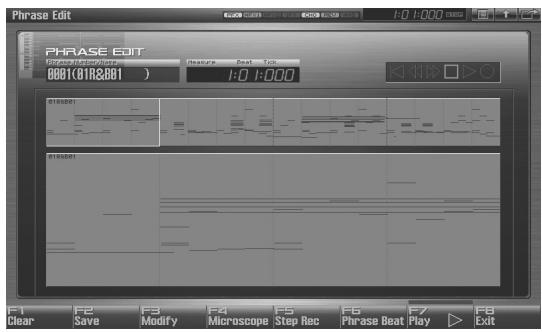
text_image
PHRASE EDIT PHRASE EDIT 0001(C01R&801) Feature Beat Tools 1:0 1:000 F1 Clear F2 Save F3 Modify F4 Microscope Step Rec F5 Step Rec F6 Phrase Beat Play ▶ F7 ExitF-key operations in the Phrase Edit screen
| F-key | Explanation | Page | |
| F1 Clear | Erases the currently-edited phrase. The phrase file itself that's saved in the project will not be deleted. | p. 239 | |
| F2 Save | Saves the phrase to the project. | p. 239 | |
| F3 Modify | Quantize | Corrects the timing of the phrase | p. 240 |
| Erase | Erases unwanted performance data | p. 242 | |
| Delete | Deletes unwanted measures | p. 243 | |
| Copy | Copies data | p. 243 | |
| Insert | Inserts blank measures | p. 244 | |
| Transpose | Transposes the pitch | p. 244 | |
| Change Velocity | Changes the velocity (volume) | p. 245 | |
| Change Channel | Changes the MIDI channel | p. 246 | |
| Change Duration | Changes the length of the notes | p. 247 | |
| Shift Clock | Moves the performance data forward or backward | p. 248 | |
| Data Thin | Thins-out performance data | p. 249 | |
| Truncate | Deletes the blank region at the beginning | p. 249 | |
| F4 Microscope | Edits individual MIDI messages and performance data recorded in the phrase. | p. 250 | |
| F5 Step Rec | Executes step recording, allowing you to enter notes and rests individually. | p. 226 | |
| F6 Phrase Beat | Specifies the time signature of a phrase. | p. 239 | |
| F7 Play | Plays the currently-edited phrase. | p. 238 | |
| F6 Exit | Returns to the previous screen. | - | |
Playing a Phrase (Play)
Here's how to play the currently-edited phrase.
- Access the Phrase Edit screen (p. 238).
- Press [PLAY] or [F7 (Play)].
Erasing the Currently-edited Phrase (Clear)
Here's how to erase the currently-edited phrase. This operation will not delete the phrase file that's saved in the project.
-
Access the Phrase Edit screen (p. 238).
-
Press [F1 (Clear)].
A confirmation message will appear.
- Press [F7 (OK)] to execute.
If you decide to cancel, press [F8 (EXIT)].
Saving a Phrase (Save)
This operation will save the phrase to the project.
A phrase you recorded or edited is temporary, and will be lost when you turn off the power. If you want to keep the phrase, you must save it.
-
Access the Phrase Edit screen (p. 238).
-
Press [F2 (Save)].
-
Assign a name to the phrase.
For details on assigning a name, refer to “Assigning a Name” (p. 42).
- When you've finished assigning a name, press [F8 (OK)].
A screen will appear where you can select the writing-destination phrase.
-
Turn the VALUE dial or use [INC] [DEC] to select the phrase number.
-
Press [F8 (Write)].
A message will ask you to confirm the Write operation.
Never turn off the power while writing is in progress.
- Press [F7 (OK)] to execute.
If you decide to cancel, press [F8 (EXIT)].
Specifying the Time Signature of a Phrase (Phrase Beat)
Here's how to specify the time signature of a phrase.
-
Access the Phrase Edit screen (p. 238).
-
Press [F6 (Phrase Beat)].
-
Use the cursor buttons and the Value dial to specify the time signature of the phrase.
-
Press [F8 (Close)].
Phrase Modify Menu
-
Access the Phrase Edit screen (p. 238).
-
Press [F3 (Modify)].
The Phrase Modify Menu window will appear.
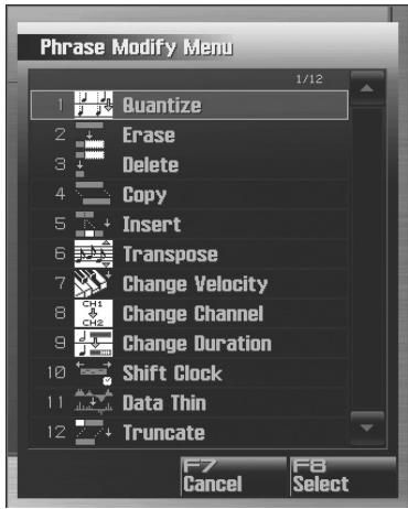
text_image
Phrase Modify Menu 1 Quantize 2 Erase 3 Delete 4 Copy 5 Insert 6 Transpose 7 Change Velocity 8 Change Channel 9 Change Duration 10 Shift Clock 11 Data Thin 12 Truncate F7 Cancel F8 Select- Use ▲ / ▼ to choose the desired function, and then press [F8 (Select)].
Quantize → p. 240
Erase → p. 242
Delete → p. 243
Copy p. 243
Insert → p. 244
Transpose → p. 244
Change Velocity → p. 245
Change Channel → p. 246
Change Duration → p. 247
Shift Clock → p. 248
Data Thin → p. 249
Truncate → p. 249
MEMO
When the phrase modify menu is displayed, you can press a dynamic pad to jump to the respective modify screen.
cf.
For details on the edit window for each phrase modify function, refer to the corresponding explanation.
-
Set the parameters of the edit function you chose. Use [CURSOR] to move the cursor to the desired parameter, and turn the VALUE dial or use [INC] [DEC] to make settings. Verify that you've selected the object you intended to edit, and make changes if necessary.
-
Press [F8 (Execute)] to execute.
When the operation is completed, the display will briefly indicate "Completed!".
TIP
If you decide to cancel, press [F7 (Cancel)].
MEMO
You can Undo the result of editing (p. 217).
Aligning a Phrase's Timing (Quantize)
In the chapter “Recording MIDI” (p. 217), we explained Recording Quantize, which lets you quantize during realtime recording.
Alternatively, it is also possible to quantize a phrase that has already been recorded.
NOTE
The Quantize operation will correct only the timing at which notes were pressed (note-on) and released (note-off), and will not correct any other sequencer data. This means that if you record MIDI messages such as bend range or modulation along with notes, quantization can cause the notes to go out of sync with the MIDI messages, skewing timing. To avoid such problems it is better to record non-keyboard data afterward, using mix recording, etc.
cf.
For details on the settings, refer to “Phrase Modify Menu” (p.239)
Part Group
Specifies the Part Group.
| Value | Explanation |
| Internal | Internal (internal sound generator) |
| EXP1 | Expansion board 1 |
| EXP2 | Expansion board 2 |
| External | External MIDI output |
| ALL | All part group |
Ch (MIDI Channel)
Specifies the MIDI channel(s) of the notes to be quantized.
If you wish to quantize all notes, set this parameter to "ALL." When quantizing only the notes of a specific MIDI channel, select that channel.
Value: ALL, Ch1–Ch16
Measure, For (Edit Range)
Sets the range of measures that are to be quantized. If you set "For" to "ALL," all measures will be specified.
Quantize Type
Specifies the Quantize range.
Value
GRID:
Grid Quantize will be applied to recording. Since the notes will be adjusted to the timing of the specified note value, you can use this when you want drums or bass (for example) to play in an accurate rhythm.
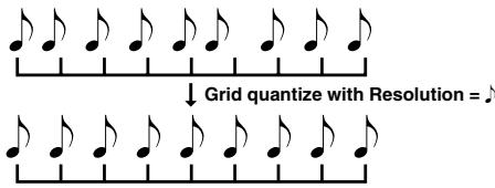
text_image
Grid quantize with Resolution = ♪SHUFFLE:
Shuffle Quantize will be applied to recording. Use this when you want to produce a "shuffle" or "swing" rhythmic feel.
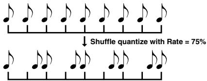
text_image
↓ Shuffle quantize with Rate = 75%TEMPLATE:
The Fantom-G provides 71 quantize templates. These templates contain various quantize settings for applying rhythmic ‘feels’ of many different musical categories. Select the template you want for quantization.
* If your sequencer data notes are too far off from accurate time, Template Quantize may not work that efficiently so you won't achieve the desired results. If this is the case, apply Grid Quantize to your sequencer data first to lose timing mistakes.
Resolution (Grid Quantize Resolution)
This parameter is used when Grid Quantize is selected. Specifies quantization time interval as a note value. Choose a Resolution that matches the smallest note in the area you're quantizing.
Value: ♣, ♣₃, ♣, ♣₃, ♣, ♣₃, ♣
Strength (Grid Quantize Strength)
This parameter is used when Grid Quantize is selected. This parameter specifies a percentage of how note timing will be corrected toward the timing interval that is specified by the Resolution parameter. With a setting of “100%,” the note will move all the way to the nearest timing interval of the Grid Resolution setting. A setting of “0%” will not change note timing at all.
Resolution (Shuffle Quantize Resolution)
This parameter is used when Shuffle Quantize is selected. Specifies quantization time interval as a note value.
Value: ♪, ♪
Rate (Shuffle Quantize Rate)
This parameter is used when Shuffle Quantize is selected. Specifies how far apart you want a down-beat specified by the Shuffle Resolution parameter to be from the up-beat that immediately follows. By shifting the timing of an up-beat, you can create a “swing” feel. A setting of “50%” will place the timing of the up-beat note at the exact mid point between the down-beat and the next down-beat. A setting of “0%” will move the up-beat note to the same timing as the previous down-beat. A setting of “100%” will move it to the same timing as the following down-beat.
Value: 0–100%
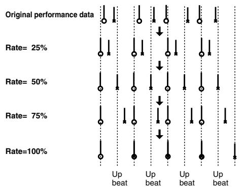
bar
| Rate | Condition | Up beat | Up beat | | -------- | --------- | ------- | ------- | | 25% | Original | Yes | Yes | | 25% | Rate | No | No | | 50% | Original | Yes | Yes | | 50% | Rate | No | No | | 75% | Original | Yes | Yes | | 75% | Rate | No | No | | 100% | Original | Yes | Yes | | 100% | Rate | No | No |Quantize Template (Quantize Template)
Specifies the template you wish to use.
Here is a list of preset groove templates.
| 001 | Dance (small dynamics) |
| 002 | Dance (large dynamics) |
| 003 | Dance (light swing) |
| 004 | Dance (heavy swing) |
| 005 | Dance (dragging beats, small dynamics) |
| 006 | Dance (dragging beats, large dynamics) |
| 007 | Dance (dragging beats, light swing) |
| 008 | Dance (dragging beats, heavy swing) |
| 009 | Dance (pushing beats, small dynamics) |
| 010 | Dance (pushing beats, large dynamics) |
| 011 | Dance (pushing beats, light swing) |
| 012 | Dance (pushing beats, heavy swing) |
| 013 | Fusion (small dynamics) |
| 014 | Fusion (large dynamics) |
| 015 | Fusion (light swing) |
| 016 | Fusion (heavy swing) |
| 017 | Fusion (dragging beats, small dynamics) |
| 018 | Fusion (dragging beats, large dynamics) |
| 019 | Fusion (dragging beats, light swing) |
| 020 | Fusion (dragging beats, heavy swing) |
| 021 | Fusion (pushing beats, small dynamics) |
| 022 | Fusion (pushing beats, large dynamics) |
| 023 | Fusion (pushing beats, light swing) |
| 024 | Fusion (pushing beats, heavy swing) |
| 025 | Reggae (small dynamics) |
| 026 | Reggae (large dynamics) |
| 027 | Reggae (light swing) |
| 028 | Reggae (heavy swing) |
| 029 | Reggae (dragging beats, small dynamics) |
| 030 | Reggae (dragging beats, large dynamics) |
| 031 | Reggae (dragging beats, light swing) |
| 032 | Reggae (dragging beats, heavy swing) |
| 033 | Reggae (pushing beats, small dynamics) |
| 034 | Reggae (pushing beats, large dynamics) |
| 035 | Reggae (pushing beats, light swing) |
| 036 | Reggae (pushing beats, heavy swing) |
| 037 | Pops (small dynamics) |
| 038 | Pops (large dynamics) |
| 039 | Pops (light swing) |
| 040 | Pops (heavy swing) |
| 041 | Pops (dragging beats, small dynamics) |
| 042 | Pops (dragging beats, large dynamics) |
| 043 | Pops (dragging beats, light swing) |
| 044 | Pops (dragging beats, heavy swing) |
| 045 | Pops (pushing beats, small dynamics) |
| 046 | Pops (pushing beats, large dynamics) |
| 047 | Pops (pushing beats, light swing) |
| 048 | Pops (pushing beats, heavy swing) |
| 049 | Rhumba (small dynamics) |
| 050 | Rhumba (large dynamics) |
| 051 | Rhumba (light swing) |
| 052 | Rhumba (heavy swing) |
| 053 | Rhumba (dragging beats, small dynamics) |
| 054 | Rhumba (dragging beats, large dynamics) |
| 055 | Rhumba (dragging beats, light swing) |
| 056 | Rhumba (dragging beats, heavy swing) |
| 057 | Rhumba (pushing beats, small dynamics) |
| 058 | Rhumba (pushing beats, large dynamics) |
| 059 | Rhumba (pushing beats, light swing) |
| 060 | Rhumba (pushing beats, heavy swing) |
| 061 | Samba (for Pandeiro, etc.) |
| 062 | Samba (for Surdo, Timbale) |
| 063 | Axe (for Caixa) |
| 064 | Axe (for Surdo) |
| 065 | Salsa (for Cascala) |
| 066 | Salsa (for Conga) |
| 067 | Triplets |
| 068 | Quintuplets |
| 069 | Sextuplets |
| 070 | Septuplets over two beats |
| 071 | Lagging triplets |
* The templates are designed for a 4/4 time signature. Applying them to a performance of a different time signature may not produce the desired result.
* The style names shown here are only for your convenience; they are not intended to imply that the templates are usable only for the named style. You can certainly try them with other styles of music.
Timing (Quantize Timing)
This specifies how much a note will move toward the timing interval of the template you pick. At a setting of 100%, the note will be perfectly timed with the template. At a setting of 0%, the note will not move at all.
Value: 0–100%
Range Min, Range Max
Specifies the range of note numbers to be quantized.
For example, if you want to quantize the range between C3 and C4, set "Note Min" to "C3," and set "Note Max" to "C4."
You can also specify the key range by pressing keys on the keyboard.
Erasing Unwanted Performance Data (Erase)
This function erases all the sequencer data inside the specified area. As the erased data is replaced by rests, the original measures will remain.
For details on the settings, refer to “Phrase Modify Menu” (p.239).
Part Group
Specifies the Part Group.
| Value | Explanation |
| Internal | Internal (internal sound generator) |
| EXP1 | Expansion board 1 |
| EXP2 | Expansion board 2 |
| External | External MIDI output |
| ALL | All part group |
Ch (MIDI Channel)
Selects the MIDI channel of the data to be erased.
When you want to erase all sequencer data, set this parameter to "ALL." To erase sequencer data of one specific MIDI channel only, select that MIDI channel.
Value: ALL, Ch1–Ch16
Measure, For (Edit Range)
Specifies the range of measures that are to be erased. If you set "For" to "ALL," all measures will be specified.
Status
Selects the type of data to be erased.
Value
ALL
NOTE
Poly Aftertouch
Control Change
Program Change
Channel Aftertouch
Pitch Bend
System Exclusive
Tune Request
Range Min, Range Max
If you have set the Status parameter to "NOTE," "P.AFT," "C.C," or "PROG," specify the range. Set "Range Min" to the lowest value of the range, and "Range Max" to the highest value of the range.

To erase all notes or polyphonic aftertouch data, set "Range Min" to "C -1" and "Range Max" to "G9." To erase C4, set "Range Min" and "Range Max" to "C4." To erase C3 through C4, set "Range Min" to "C 3" and "Range Max" to "C4."
- To erase all controller numbers, set "Range Min" to "0" and "Range Max" to "127." To erase all program numbers, set "Range Min" to "1" and "Range Max" to "128." To erase number 4, set "Range Min" and "Range Max" to "4." To erase numbers 3 through 14, set "Range Min" to "3" and "Range Max" to "14."
Deleting Unwanted Measures (Delete)
This function deletes a specified area of sequencer data, and moves the subsequent data to fill the gap. As a result, the measure length will be shortened by the number of deleted measures.
For details on the settings, refer to “Phrase Modify Menu” (p.239).
Measure, For (Edit Range)
Specifies the range of measures that are to be deleted. If you set "For" to "ALL," all measures will be specified.
Copying Phrases (Copy)
This function copies a specified area of sequencer data.
For details on the settings, refer to “Phrase Modify Menu” (p.239).
Part Group
Specifies the Part Group.
| Value | Explanation |
| Internal | Internal (internal sound generator) |
| EXP1 | Expansion board 1 |
| EXP2 | Expansion board 2 |
| External | External MIDI output |
| ALL | All part group |
Ch (MIDI Channel)
Selects the MIDI channel of the data to be copied.
When you want to copy all the sequencer data, set this parameter to "ALL." To copy only the sequencer data of a specific MIDI channel, select the MIDI channel.
Value: ALL, Ch1–Ch16
Src Measure, For (Edit Range)
Specifies the range of copy-source measures. If you set "For" to "ALL," all measures will be specified.
Dst Measure (Destination Measure)
Specifies the copy-destination measure.
If you want the copy destination to be right after the last measure of a phrase, set this parameter to "END."
Copy Mode
Specifies whether you want to preserve the existing data in the copy destination when copying.
Value
MIX: Combines the data from the copy source with the existing data in the copy destination.
REPLACE: Musical data in the copy destination will be erased (i.e., overwritten) when the copy takes place. Only the sequencer data of the MIDI channels specified by the Channel parameter will be overwritten, and data of other MIDI channels will remain.
Copy Times
Specifies the number of times that the data will be copied to the copy destination.
Status
Selects the type of data to be copied.
Value
ALL
NOTE
Poly Aftertouch
Control Change
Program Change
Channel Aftertouch
Pitch Bend
System Exclusive
Tune Request
Range Min, Range Max
If you have selected "NOTE," "P.AFT," "C.C," or "PROG" for the Status parameter, specify the range. Set "Range Min" to the lowest value of the range, and "Range Max" to the highest value of the range.

To copy all notes or polyphonic aftertouch data, set "Range Min" to "C-1" and "Range Max" to "G9." To copy C4, set "Range Min" and "Range Max" to "C4." To copy C3 through C4, set "Range Min" to "C3" and "Range Max" to "C4."
- To copy all controller numbers, set "Range Min" to "0" and "Range Max" to "127." To copy all program numbers, set "Range Min" to "1" and "Range Max" to "128." To copy number 4, set "Range Min" and "Range Max" to "4." To copy numbers 3 through 14, set "Range Min" to "3" and "Range Max" to "14."
Inserting a Blank Measure (Insert)
This function inserts blank measures into a specified phrase position.
For details on the settings, refer to “Phrase Modify Menu” (p.239).
Measure, For (Edit Range)
Specifies the measure location at which the blank measures are to be inserted, and the number of blank measures to be inserted.
Transpose the Key (Transpose)
This transposes the pitch of notes within a specified area, over a +/- 127 semitone range. Use this function to modulate from one key to another in a phrase, or to transpose the entire phrase.
For details on the settings, refer to “Phrase Modify Menu” (p.239).
Part Group
Specifies the Part Group.
| Value | Explanation |
| Internal | Internal (internal sound generator) |
| EXP1 | Expansion board 1 |
| EXP2 | Expansion board 2 |
| External | External MIDI output |
| ALL | All part group |
Ch (MIDI Channel)
Specifies the MIDI channel(s) of the notes to be transposed.
Set this parameter to “ALL” for transposing all notes. When transposing only the notes of specific MIDI channel(s), select the MIDI channel(s) using this parameter.
Value: ALL, Ch1–Ch16
Measure, For (Edit Range)
Sets the range of measures that are to be transposed. If you set "For" to "ALL," all measures will be specified.
Range Min, Range Max
Specifies the range of note numbers to be transposed. For example, if you want to transpose notes in the range of C3 through C4, set "Range Min" to "C3" and "Range Max" to "C4." You can also specify the key range by pressing keys on the keyboard.
Bias
Specifies the transpose amount in semitone steps. Set a “+” (positive) value to raise the pitch, or a “-” (negative) value to lower the pitch. If you do not want to transpose, set this to “0.”
Value: -127- +127
If You Want to Lower the Bass Sound One Octave...
If your bass is played one octave higher than the staff notation, use the Transpose function to lower it one octave.
To lower the bass sound one octave, set the Range parameter to "Lowest-Highest" for the bass part, and set the Bias parameter to "-12."
When You Want to Change Percussion Sounds...
You can also use the Transpose function to change percussion sounds.
Suppose you want to change conga to tom. If the conga sound is assigned to the D4 key, and the tom sound is assigned to the C3 key, set the Range parameter to "D4–D4" and the Bias parameter to "-14."
Changing the Velocity (Change Velocity)
This function modifies the keyboard playing dynamics (velocity) of a specified note area.

For details on the settings, refer to “Phrase Modify Menu” (p. 239).
Part Group
Specifies the Part Group.
| Value | Explanation |
| Internal | Internal (internal sound generator) |
| EXP1 | Expansion board 1 |
| EXP2 | Expansion board 2 |
| External | External MIDI output |
| ALL | All part group |
Ch (MIDI Channel)
Specifies the MIDI channel(s) of notes for which velocity will be modified.
To modify velocity for all notes, set this parameter to "ALL." When modifying the velocity for only the notes of a specific MIDI channel, select that MIDI channel using this parameter.
Value: ALL, Ch1–Ch16
Measure, For (Edit Range)
Specifies the range of measures whose velocity will be changed. If you set "For" to "ALL," all measures will be specified.
Bias
Use this parameter to add a fixed bias amount to all velocities. If you want to increase the velocity values by 10, set this to “+10.”
Value: -99- +99
Magnify
Set this parameter if increases or decreases in velocity variations are desired. For less velocity variation, use settings of "99%" or less. For more velocity variation, set it to "101%" or greater. With a setting of "100%," velocity values do not change.
Value: 0–200%
Range Min, Range Max
Specifies the range of note numbers for which velocity will be modified. For example, if you want to modify the velocity of notes in the range of C3 through C4, set “Range Min” to “C3” and “Range Max” to “C4.” You can also specify the key range by pressing keys on the keyboard.
Changing the MIDI Channel (Change Channel)
This function transfers the MIDI channel of a specified area of sequencer data into a different MIDI channel.
For details on the settings, refer to “Phrase Modify Menu” (p.239).
Part Group
Specifies the Part Group.
| Value | Explanation |
| Internal | Internal (internal sound generator) |
| EXP1 | Expansion board 1 |
| EXP2 | Expansion board 2 |
| External | External MIDI output |
| ALL | All part group |
Measure, For (Edit Range)
Specifies the range of measures in which the MIDI channel will be changed. If you set “For” to “ALL,” all measures will be specified.
Status
Selects the type of data for which you wish to change the MIDI channel.
Value
ALL
NOTE
Poly Aftertouch
Control Change
Program Change
Channel Aftertouch
Pitch Bend
Range Min, Range Max
If you have set the Status parameter to "NOTE," "P.AFT," "C.C," or "PROG," you can specify the range of data. Set "Range Min" to the lowest value of the range, and "Range Max" to the highest value of the range.

To change the MIDI channel of all notes or polyphonic aftertouch data, set "Range Min" to "C -1" and "Range Max" to "G9." To change the MIDI channel of C4, set "Range Min" and "Range Max" to "C4." To change C3 through C4," set "Range Min" to "C3" and "Range Max" to "C4."
- To change the MIDI channel of all controller numbers, set "Range Min" to "0" and "Range Max" to "127." To change the MIDI channel of all program numbers, set "Range Min" to "1" and "Range Max" to "128." To change number 4, set "Range Min" and "Range Max" to "4." To change numbers 3 through 14, set "Range Min" to "3" and "Range Max" to "14."
Src Channel, Dst Channel (MIDI Channel)
Set Src Channel to the MIDI channel that you want to change, and set Dst Channel to the MIDI channel to which it will be changed. If you have selected ALL for the source MIDI channel, the sequencer data of all MIDI channels will be combined into the destination MIDI channel.
Value: ALL, 1–16

It is not possible to select "ALL" for the destination MIDI channel.
Modifying the Length of Notes (Change Duration)
This function modifies the duration (time from note-on to note-off) of notes within a specified area. Depending on the setting, you can also create staccato or tenuto.
cf.
For details on the settings, refer to “Phrase Modify Menu” (p.239).
Part Group
Specifies the Part Group.
| Value | Explanation |
| Internal | Internal (internal sound generator) |
| EXP1 | Expansion board 1 |
| EXP2 | Expansion board 2 |
| External | External MIDI output |
| ALL | All part group |
Ch (MIDI Channel)
Specifies the MIDI channel(s) of notes for which duration will be modified.
If you wish to modify the duration for notes of all MIDI channels, set this parameter to ALL. When changing the duration for notes of a specific MIDI channel only, select that MIDI channel using this parameter.
Value: ALL, Ch1–Ch16
Measure, For (Edit Range)
Specifies the range of measures whose durations will be changed. If you set "For" to "ALL," all measures will be specified.
Bias
Set this parameter if you wish to increase or decrease all durations by a fixed amount. If you want to extend all duration by 10, set this to “+10.”
Value: -4800- +4800
Magnify
Set this parameter if you wish to increase or decrease durations by a specified ratio. When set to “100%,” no change is made. A value of “101%” or higher increases the duration; values of “99%” or lower decrease the duration. For example, to halve duration, set this parameter to “50%.” To double durations, set this parameter to “200%.”
Value: 0–200%
Range Min, Range Max
Specifies the range of note numbers for which duration will be modified. For example, if you want to change the duration of notes in the range of C3 to C4, set “Range Min” to “C3” and “Range Min” to “C4.” You can also specify the key range by pressing keys on the keyboard.
Shifting Performance Data Forward and Back (Shift Clock)
This function shifts the timing of sequencer data backward or forward in time within a specified area in steps of 1 tick. Slight shifts of timing can speed up or drag performance.
NOTE
When this function is executed, data that would be moved to a point before the beginning of the phrase will automatically shift to the beginning of the phrase. If data would be moved to a point past the end of the phrase, additional new measures will be created automatically as needed. The time signature of the newly created measures will be the same as that of the measure immediately preceding.
cf.
For details on the settings, refer to “Phrase Modify Menu” (p.239)
Part Group
Specifies the Part Group.
| Value | Explanation |
| Internal | Internal (internal sound generator) |
| EXP1 | Expansion board 1 |
| EXP2 | Expansion board 2 |
| External | External MIDI output |
| ALL | All part group |
Ch (MIDI Channel)
Selects the MIDI channel of the data to be shifted in time.
To shift ticks of all sequencer data, set this parameter to "ALL." To shift the sequencer data tick of just one specific MIDI channel, select that MIDI channel.
Value: ALL, Ch1–Ch16
Measure, For (Edit Range)
Specifies the range of measures in which the sequencer data will be moved in units of one tick. If you set "For" to "ALL," all measures will be specified.
Bias
Specify the amount (number of ticks) by which the sequencer data will be moved.
Value: -4800- +4800
Status
Selects the type of data to be shifted in time.
Value
ALL
NOTE
Poly Aftertouch
Control Change
Program Change
Channel Aftertouch
Pitch Bend
System Exclusive
Tune Request
Range Min, Range Max
If you set the Status parameter to "NOTE," "P.AFT," "C.C," or "PROG," specify the range of data. Set "Range Min" to the lowest value of the range, and "Range Max" to the highest value of the range.
TIP
To shift all notes or polyphonic aftertouch data, set "Range Min" to "C -1" and "Range Max" to "G9." To shift C4, set "Range Min" and "Range Max" to "C4." To shift C3 through C4, set "Range Min" to "C3" and "Range Max" to "C4."
- To shift all controller numbers, set "Range Min" to "0" and "Range Max" to "127." To shift all program numbers, set "Range Min" to "1" and "Range Max" to "128." To shift number 4, set "Range Min" and "Range Max" to "4." To shift numbers 3 through 14, set "Range Min" to "3" and "Range Max" to "14."
Thinning Out the Sequencer Data (Data Thin)
Continuously variable controllers such as aftertouch, pitch bend, and expression tend to create unexpectedly large amounts of data when operated. Data Thin will strip out redundant data to increase the amount of memory available for the sequencer.
For details on the settings, refer to “Phrase Modify Menu” (p.239).
Part Group
Specifies the Part Group.
| Value | Explanation |
| Internal | Internal (internal sound generator) |
| EXP1 | Expansion board 1 |
| EXP2 | Expansion board 2 |
| External | External MIDI output |
| ALL | All part group |
Ch (MIDI Channel)
Selects MIDI channel of the data to be thinned.
To thin all sequencer data, set this parameter to “ALL.” To thin sequencer data of just one specific MIDI channel, select that MIDI channel.
Value: ALL, Ch1–Ch16
Measure, For (Edit Range)
Specifies the range of measures whose sequencer data will be thinned. If you set “For” to “ALL,” all measures will be specified.
Data Thin Value
For thinning data which incorporates rapid changes, use higher settings. If you don't want to thin that much data even though it is subject to rapid change, use lower settings.
Data Thin Time
If you are thinning data that changes gradually over time, use higher settings. If you don't want to thin that much data even though the changes are gradual, use lower settings.
Status
Selects the type of data to be thinned.
Value
ALL
Poly Aftertouch
Control Change
Channel Aftertouch
Pitch Bend
Range Min, Range Max
If you set the Status parameter to "P.AFT" or "C.C," specify the range of data. Set "Range Min" to the lowest value of the range, and "Range Max" to the highest value of the range.

To thin out all polyphonic aftertouch data, set "Range Min" to "C -1" and "Range Max" to "G9." To thin out C4, set "Range Min" and "Range Max" to "C4." To thin out C3 through C4, set "Range Min" to "C3" and "Range Max" to "C4."
- To thin out all controller numbers, set "Range Min" to "0" and "Range Max" to "127." To thin out number 4, set "Range Min" and "Range Max" to "4." To thin out numbers 3 through 14, set "Range Min" to "3" and "Range Max" to "14."
Deleting Blank Measures (Truncate)
Copying may sometimes create blank measures at the beginning of a phrase. Truncate deletes silent portions from the beginning of the specified phrase to the first note-on.
NOTE
If other sequencer data (such as program changes or control changes) is recorded between the beginning and the first note-on of the specified phrase, only the last data event of each type will be placed before the note-on.
For details on the settings, refer to “Phrase Modify Menu” (p.239).
- Press [F8 (Execute)] to execute the Truncate operation.
Editing Individual Items of Sequencer Data (Microscope)
Microscope lets you edit individual items of sequencer data recorded in a phrase, such as MIDI messages.
Editing Sequencer Data (Basic Procedure in the Microscope)
Access the Microscope screen when you want to view the sequencer data recorded in a phrase. Each line indicates the location (measure-beat-tick) at which the sequencer data is recorded, and the data recorded at that location.
1. Access the Phrase Edit screen (p. 238).
2. Press [F4 (Microscope)].
The Microscope screen will appear.
Use ▲ / ▼ to view the performance data.
![ROLAND FANTOM G8 - Press [F4 (Microscope)]. - 1](/content/2025/01/130804/images/cd96a98fb95d09507b9dd933f49eea13448eef346ac1a1c42a23e86b3fecf9b3.jpg)
text_image
Indicates the parameter data at the cursor location MIDI channel Microscope 1:01-000 Microscope 8881(MIDI Phrase8881) 1:01-000 ALL (AT-Q1E) On AP Touch 8881 1-01-000 / Track 52/6 31 115 0-001 64 012 / Channel 9/4/6 Touch 13 091 / Channel 9/4/6 Touch 15 100 / Channel 9/4/6 Touch 21 101 / Channel 9/4/6 Touch 65 0-000 64 110 / Channel 9/4/6 Touch 25 120 / Channel 9/4/6 Touch 38 129 / Channel 9/4/6 Touch 54 206 / Channel 9/4/6 Touch 25 215 / Channel 9/4/6 Touch 34 216 / Track 52/6 31-180 0-000 64 217 / Track 52/6 31-180 0-000 64 Performance data Location of the performance data (Measure - Beat - Tick) Part Group INT EXP1 EXP2 EXTF-key operations in the Microscope screen
| F-key | Explanation | Page |
| F1Create | Inserts data. | p. 252 |
| F2Erase | Erases data. | p. 252 |
| F3Move | Moves data. | p. 253 |
| F4Copy | Copies data. | p. 253 |
| F5Place | Pastes the copied data. | p. 253 |
| F6☐ | Switches the display of the piano roll. | p. 250 |
| F7Channel | Switches the part whose data is displayed. | p. 250 |
| F8View | Selects the data that is displayed. | p. 252 |
3. You can press [F6 (☐)] to switch the display of the piano roll.
4. Press [F7 (Channel)] to select the part whose performance data you want to view or edit.
Choose "ALL" if you want to view performance data of all MIDI channels.
Channel: ALL, 1–16
Part Group: ALL, INT, EXP1, EXP2, EXT
MEMO
In order to make efficient use of the display space in the screen, locations in which no performance data exists are normally not shown.
cf.
For an explanation of the various types of performance data, refer to “Sequencer Data Handled by Phrases” (p. 251).
5. When you've finished editing, press [F8 (Close)].
6. Use ▲ / ▼ to select the performance data that you want to edit.
7. Use ◀ / ▶ to select the parameter that you want to edit.
8. Turn the VALUE dial or use [INC] [DEC] to change the value.
TIP
Notes, the note name (note number) of polyphonic aftertouch data, and the on-velocity or off-velocity of a note can also be specified by pressing a note on the keyboard.
TIP
If you press [ENTER], the performance data currently indicated by “■” will be transmitted from the MIDI OUT connector. In the case of a note message, pressing [ENTER] will sound that note.
cf.
If you're editing a system exclusive message, refer to "Editing a system exclusive message" on the following page.
9. Repeat steps 3 through 8 to edit the data.
10. To close the Microscope screen, press [EXIT].
MEMO
You can Undo the result of editing (p. 217).
Editing a System Exclusive Message
-
Use ▲ or ▼ to move the cursor to the location of the system exclusive message that you want to edit.
-
Press ▶.
The System Exclusive Edit window appears.
-
Press ◀ or ▶ to move the cursor to the data that you want to edit.
-
Turn the VALUE dial or press [INC] [DEC] to edit the value. If you want to add data between "F0:" and ":F7," move the cursor to that location and press [F3 (Insert)]. A value of "00" will be inserted. Change this to the desired value. To delete data, move the cursor to the relevant location and press [F2 (Delete)].
-
When you are finished editing, press [F8 (Execute)] to finalize the values of the system exclusive message. To cancel, press [F7 (Cancel)].
TIP
If you decide to discard the changes you made to the system exclusive message and return to the Microscope screen, press [EXIT].
- In the case of a Roland type IV system exclusive message, the checksum can be calculated automatically when you finalize the values. If you do not want to calculate the checksum automatically, press [F1 (Auto Sum)] to turn off the light.
- When you press [F4 (Test)], the system exclusive message you are editing will be transmitted from the MIDI OUT connector.
Sequencer Data Handled by Phrases
Phrases can record the following eight types of sequencer data. The recorded location (measure-beat-tick) is displayed at the far left of each data item, and the MIDI channel number is displayed beside it.
Note
These MIDI messages represent notes. From the left, the parameters are Note Number, which indicates the name of the note; On Velocity, which specifies the force with which the key is pressed; Duration, which specifies the duration of the note; and Off Velocity, which determines the force with which the key is released.
Program Change
This MIDI message switches sounds. The program number (PC#) selects the sound.
Control Change
This MIDI message applies various effects such as modulation or expression. The controller number (CC#) selects the function, and Value specifies the depth of the effect.
Pitch Bend
This MIDI message changes the pitch. The value specifies the amount of pitch change.
Poly Aftertouch
This MIDI messages apply aftertouch to an individual note. From the left, the parameters are Note Number which specifies the key, and Value which specifies the depth of the aftertouch.
Channel Aftertouch
This MIDI message applies aftertouch to an entire MIDI channel. Value specifies the depth of the aftertouch.
System Exclusive
These are MIDI messages used to make settings unique to the Fantom-G, such as sound settings. Input the data between "F0" and "F7."
Tune Request
This MIDI message causes an analog synthesizer to tune itself.
Viewing Sequencer Data (View)
Since a phrase contains a large amount of sequencer data, the display may be cluttered and difficult to read. For this reason, the Fantom-G lets you specify the type(s) of sequencer data that will be displayed in the screen. This is convenient when you want to check or edit only a specific type of sequencer data.
-
Access the Microscope screen (p. 250).
-
Press [F8 (View)].
The View Select window appears.
- Use ▲ or ▼ to select the sequencer data that will be displayed.
| Note: | Note messages. These MIDI messages represent notes. |
| Poly Aftertouch: | Polyphonic aftertouch. These MIDI messages apply aftertouch to individual keys. |
| Control Change: | Control change messages. These MIDI messages apply various effects such as modulation or expression. |
| Program Change: | Program change messages. These MIDI messages select sounds. |
| Channel Aftertouch: | Channel aftertouch messages. These MIDI messages apply aftertouch to an entire MIDI channel. |
| Pitch Bend: | Pitch bend messages. These MIDI messages change the pitch. |
| System Exclusive: | System exclusive messages. These MIDI messages are used to make settings unique to the Fantom-G, such as those for the sound parameters. |
| Tune Request: | This MIDI Message cause an analog synthesizer to tune it self. |
- Press [INC] or [DEC] to switch.
If you press [F6 (ALL OFF)], none of the sequencer data will be displayed.
If you press [F7 (ALL ON)], all of the sequencer data will be displayed.
- Press [F8 (Close)] to close the View Select window.
Inserting Sequencer Data (Create)
You can insert new sequencer data into a desired location of a phrase.
For details on the sequencer data that can be inserted, refer to “Sequencer Data Handled by Phrases” (p. 251).
- Access the Microscope screen for the phrase into which you want to insert sequencer data (p. 250).
- Press [F1 (Create)].
The Create Event window appears. - Press ▲ or ▼ to select the sequencer data that will be inserted.
- Press [F8 (Execute)] to insert the performance data.
- The sequencer data that was inserted will have the default parameter values, so edit them as necessary.
Erasing Sequencer Data (Erase)
If desired, you can erase just an individual event of sequencer data.

Data recorded in the tempo track (p. 235) or beat track (p. 236) can also be erased in the same way.
You can't erase the tempo change located at the beginning of the tempo track, or the beat change and phrase beat located at the beginning of the beat track.
- Access the Microscope screen for the phrase from which you want to erase sequencer data (p. 250).
- Press ▲ or ▼ to move the cursor to the sequencer data that you want to erase.

To erase a multiple consecutive data, hold down [SHIFT] and press ▲ or ▼ to select the sequencer data.
- Press [F2 (Erase)] to erase the sequencer data.
Moving Sequencer Data (Move)
You can move an individual item of sequencer data to a different location.
MEMO
Data recorded in the tempo track (p. 235) or beat track (p. 236) can also be moved in the same way.
You can't move the tempo change located at the beginning of the tempo track, or the beat change and phrase beat located at the beginning of the beat track.
- Access the Microscope screen for the phrase whose data you want to move (p. 250).
- Press ▲ or ▼ to move the cursor to the sequencer data that you want to move.
TIP
To move a multiple consecutive data, hold down [SHIFT] and press ▲ or ▼ to select the sequencer data.
- Press [F3 (Move)].
The Move Event window appears.
- Press ◀ or ▶ to move the cursor to the “measure,” “beat,” and “tick” fields.
- Turn the VALUE dial or Press [INC] [DEC] to specify the location to which the data will be moved.
- Press [F8 (Execute)] to move the sequencer data.
Copying Sequencer Data (Copy)
Sequencer data can be copied to the desired location. This is convenient when you want to use the same sequencer data at multiple locations.
MEMO
Data recorded in the tempo track (p. 235) or beat track (p. 236) can also be copied in the same way.
- Access the Microscope screen for the phrase whose sequencer data you want to copy (p. 250).
- Press ▲ or ▼ to move the cursor to the sequencer data that you want to copy.
- Press [F4 (Copy)].
- Press [F5 (Place)].
The Place Event window appears. - Press ◀ or ▶ to move the cursor to the “measure,” “beat,” and “tick” fields.
- Turn the VALUE dial or Press [INC] [DEC] to specify the location to which the data will be copied.
- Press [F8 (Execute)] to paste the data.
A song you record is initially held in the temporary area. The song in the temporary area will be lost if you turn off the power or load a different song. If you want to keep this song, you'll need to save it to the project.
What the Saved Song Data Contains
Along with the sequencer data, the song data also contains the studio set, live set, patch, and system setup data that you were using at that time.
The studio set, live set, and patch data saved within the song data is special data for reproducing the song; it is separate from the user studio sets, live sets, and user patches.
* If you want to use this data with a different song, or to use it independently of any song, you must save the data in the user area.
What is Saved at the Same Time as the Song
The samples and phrases used by the song are automatically saved when you save the song.
Saving a Song (Save)
cf.
If you want to save phrases individually
→ “Saving a Phrase (Save)” (p. 216)
cf.
If you want to save samples individually
→ “Saving a Sample (Save)” (p. 274)
- In the Song Play screen or Song Edit screen, press [WRITE].
The WRITE MENU window appears.
- Use ▲ / ▼ to select "Song," and then press [F8 (Select)].
The Song Name window will appear.
- Assign a name to the song.
cf.
For details on how to assign a name, refer to “Assigning a Name” (p. 42).
- When you've finished assigning the name, press [F8 (OK)].
A screen will appear, allowing you to select the writing-destination song.
-
Turn the VALUE dial or use [INC] [DEC] to select a song number.
-
Press [F8 (Save)].
A writing confirmation message will appear.
NOTE
Never turn off the power while data is being written.
- To write the data, press [F7 (OK)].
* If you decide to cancel, press [F8 (EXIT)].
Resampling the Contents of All Tracks to a Single Sample
Here's how you can combine the performance of all audio tracks and MIDI tracks to a single sample.
After creating a sample in this way, you can save it on your computer or another device as a completed song.
-
Load the song that you want to resample (p. 204).
-
Press [◀] to move the song position to the beginning.
-
Press the [SAMPLING] button.
-
Press [F2 (Re-Sampling)].
-
Press [F2 (Auto Trig)].
-
Press [PLAY].
Resampling will begin.
- When the song ends, press [F7 (Stop)].
TIP
Alternatively, you can set the “Stop Trigger” (p. 260) parameter to “TIME” and set the “Sampling Length” (p. 261) parameter to the ending location of the song so that resampling will stop automatically.
- In the Sample Edit screen (p. 266), listen to the sample you just created by resampling.
TIP
The volume of resampled phrases may be less than the volume of the original phrases. As necessary, use the Normalize operation (p. 270) to raise the volume.
NOTE
The resampled sample will be lost if you turn off the power. If you want keep the sample, press [WRITE] to save it (p. 274).
Copying a Resampled Sample to Your Computer to Create a CD or MP3
A sample you created by resampling can be copied to your computer. The sample will be a WAV file, which you can use to create a CD or MP3 on your computer.
-
Verify the number of the sample you resampled. (In this example we'll assume it's number 0001.)
-
Use the USB Storage function (p. 285) to copy the following sample to your computer.
"FantomG.Prj/SMPL/0001.WAV"
(The number in the .WAV file name will be the sample number.)
MEMO
"FantomG.prj" is the name of the project folder in the Fantom-G's internal memory. Multiple projects can be saved in USB memory. By default, the project folders will be numbered as "FantomG001.Prj," "FantomG002.Prj," etc., and the portion preceding the filename extension will be the project name you assigned when saving.
Save As an SMF File (Save As SMF)
Here's how to save the song that you loaded (temporary song) or MIDI phrase as an SMF file.
- In the Song Play/Song Edit screen, press [F7 (Song Util)], choose "Save As SMF" from the menu that appears, and then press [F8 (Select)].
The Save As SMF screen will appear.
MEMO
If you want to convert a MIDI phrase to an SMF file, press [F3 (Util Menu)] in the MIDI Phrase List screen, choose "Save As SMF" from the menu that appears, and then press [F8 (Select)].
- Specify SMF Format, the desired Part Group, and then press [F8 (Execute)].
- SMF Format Select
| Format | Explanation |
| Format 0 | Convert the song to a Format 0 Standard MIDI File (all performance data is saved in one track) and save it. An extension of “.MID” will be added automatically. |
| Format 1 | Convert the song to a Format 1 Standard MIDI File (performance data is saved in more than one track) and save it. An extension of “.MID” will be added automatically. |
- Part Group
The performance data of the part group you specified will be saved as an SMF file.
| Value | Explanation |
| Internal | Internal (internal sound generator) |
| EXP1 | Expansion board 1 |
| EXP2 | Expansion board 2 |
| External | External MIDI output |
| ALL | All part group |
- Assign a file name, and then press [F8 (OK)].
A screen will ask for confirmation.
- Press [F7 (OK)] to execute.
The SMF file will be saved in the SMF folder of the project. In the case of a project in internal memory, the SMF file will be saved in the "FantomG.Prj/SEQ/SMF" folder.
* The filename extension will be “.MID” whether you select “Save SMF (Format 0)” or “Save SMF (Format 1).” The two cannot be distinguished in this way.
NOTE
When you save data in SMF format, the sound setup data will not be saved. In order to ensure that the correct sounds are played, you must record the appropriate bank select and program numbers.
NOTE
Audio tracks are not saved in an SMF file.
07: Sampler
This chapter explains how to sample sounds and edit samples.
- Sampling ...... p. 258
• Editing a Sample ...... p. 263
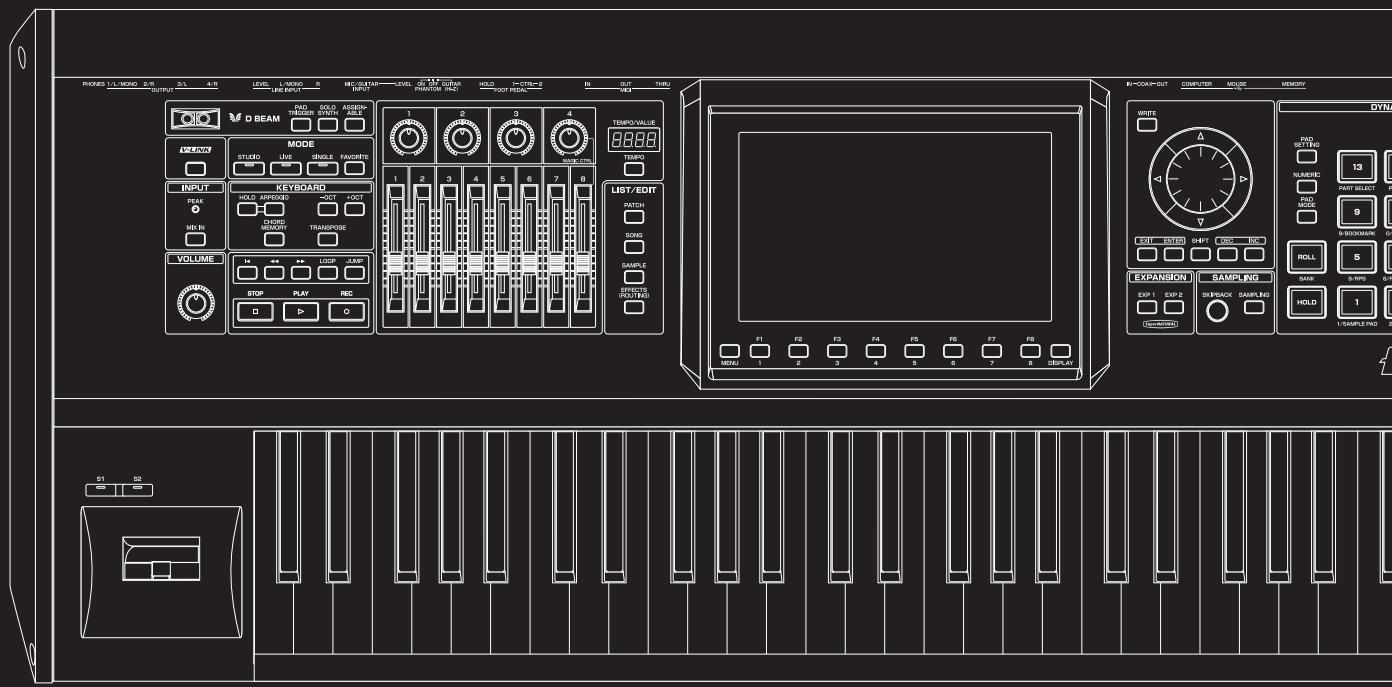
text_image
PROKES L/L MISO 2/R 3/L 4/R LEVEL L-MISO 5 MECUTAIN LEVEL 6 M.1.2 GRAV HOLD I-CTR=2 IN OUT TURI OUTPUT LINE INPUT INPUT PRANTOR PAC FOUR PIEDAL IN V8 D BEAM SODA ASSIMANCE TEMPO VALUE MODE STUDIO LIVE SINGLE FAUCERS INPUT PEAK HOLD APPROD SOCT OCT CHORD MEOCON TRANSPOSE MD IN VOLUME STOP PLAY REC LIST/EDIT PATCH DOYS SAMPLE CAPSIC (RDT/RDS) EXPANSION SAMPLING EXP 1 EXP 2 SKEEBACK SAMPLING HOLD 1 SAMPLE PAD 2 S1 SB WIFE TAB/SETTA FLAVENZA 13 FAST SELECT 0 BLOODMARK ON ROLL 5 SANK 6-RP0 6-RP1 F1 F2 F3 F4 F5 F6 F7 F8 MIN: 1 2 3 4 5 6 7 8 DISPLAYThe Fantom-G lets you sample audio sources, such as an audio device, mic, or CD.
This section explains the sampling procedure and what the parameters do.
TIP
Sampling time
The Fantom-G contains 32 MB of memory, which allows about 6 minutes of mono or about 3 minutes of stereo sampling. If you want to sample for a longer time than this, you must install separately sold memory (DIMM) (p. 312, p. 314).
* The available recording time may be shorter depending on how memory is being used.
Switching External Input On/Off
1. Press [MIX IN] to turn it on.
The button will light.
MEMO
You can use the System setting “Mix In Switch” (p. 301) to memorize the on/off setting.
2. To turn it off, press [MIX IN] again.
Making Input Source Settings (Input Setting)
1. Connect your CD player, mic, or other audio source to the AUDIO INPUT jacks, MIC/GUITAR jack or to the DIGITAL AUDIO IN connector located on the rear panel of the Fantom-G.
cf.
For details on connecting your equipment, refer to the Quick Start Guide section entitled “Connecting your equipment” (p. 38).
Cautions when using a microphone
Howling could be produced depending on the location of microphones relative to speakers. This can be remedied by:
- Changing the orientation of the microphone(s).
- Relocating microphone(s) at a greater distance from speakers.
- Lowering volume levels.
* When connection cables with resistors are used, the volume level of equipment connected to the inputs (AUDIO INPUT) may be low. If this happens, use connection cables that do not contain resistors.
* If an external device is connected to the DIGITAL AUDIO IN connector, disconnecting the cable or powering-off the external device may cause noise to be subsequently heard in the input from DIGITAL AUDIO IN. If this occurs, correctly re-connect your external device, or turn off the Fantom-G's [MIX IN] switch.
- Hold down [SHIFT] and press [MIX IN].
- Press [CURSOR] to select the parameter that you want to set.
- Turn the VALUE dial or press [INC] [DEC] to set the value.
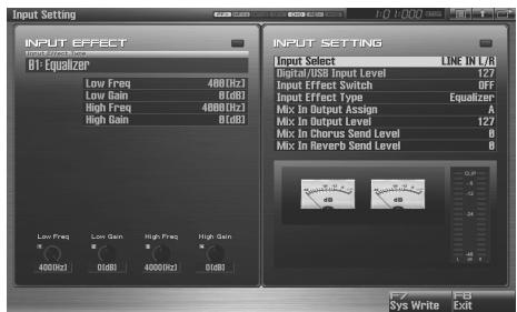
text_image
Input Setting INPUT EFFECT Output: 480Hz BF-EqualizeBP Low Freq 480Hz Low Gain 0dB1 High Freq 480Hz High Gain 0dB1 Input Select LINE IN V8 Digital/USB Input Level 127 Input Effect Switch OFF Input Effect Type Equalizer Mix In Output Assign A Mix In Output Level 127 Mix In Chorus Send Level 0 Mix In Reverb Send Level 0 Low Freq Low Gain High Freq High Gain 400Hz 0dB 4000Hz 0dB1cf.
See “Functions of Input Setting Parameters” (p. 258) for each parameter’s functions.
- Play back the external input source.
- If you use AUDIO INPUT, turn the LEVEL knob (rear panel: p. 24) to adjust the volume.
* If you're using DIGITAL AUDIO IN or USB AUDIO, this adjustment is not necessary.
* If the volume of the external source is too high, the PEAK indicator will light. If this occurs, turn down the LEVEL knob until the PEAK indicator no longer lights.
- Press [EXIT] to return to the previous screen.
Functions of Input Setting Parameters
This section explains the functions the different Input Setting parameters have, as well as the composition of these parameters.
- Mix In Switch
Turns the external input on/off.
Value: OFF, ON
- Input Select
Specifies the input source of the sound to be sampled.
Value
DIGITAL IN: DIGITAL AUDIO IN jack
LINE IN L/R: INPUT jacks L/R (stereo)
LINE IN L: INPUT jack L (mono)
MIC/GUITAR: MIC/GUITAR jack
USB AUDIO: USB connector
• Digital/USB Input Level
If you've set Input Select to DIGITAL IN or USB AUDIO, this adjusts the input level.
Value: 0–127
- Input Effect Switch
Specifies whether the external input sound will be sent through the effects processor (Input Effect).
Value: OFF, ON
- Input Effect Type
Selects the type of effect that will be applied to the external input source.
Value: Equalizer, Enhancer, Compressor, Limiter, Noise Suppressor, Center Canceler
When you press [F7 (Input Effect)], the parameter setting screen for the currently selected input effect will be displayed “Input Effect Setup Settings” (p. 259).
- Mix In Output Assign
Output destination of the external input sound that is mixed in Value
A: Output to OUTPUT (A) jacks without passing through effects
B: Output to OUTPUT (B) jacks without passing through effects
MFX1: Output through multi-effects 1
MFX2: Output through multi-effects 2 (* Studio Mode only)
EXP1: Output through expansion board 1
EXP2: Output through expansion board 2
* EXP1 or EXP2 is available only when the corresponding expansion board supports audio input.
- Mix In Output Level
Volume level of the external input sound.
Value: 0–127
• Mix In Chorus Send Level
Adjusts the depth of chorus that will be applied to the external input source. Set this to “0” if you do not want to apply chorus.
Value: 0–127
• Mix In Reverb Send Level
Depth of reverb applied to the external input sound. Set this to "0" if you don't want to apply reverb.
Value: 0–127
Input Effect Setup Settings
1. Hold down [SHIFT] and press [MIX IN].
The Input Effect Setup screen appears.
![ROLAND FANTOM G8 - Hold down [SHIFT] and press [MIX IN]. - 1](/content/2025/01/130804/images/81f052ec63c1c1beff870c9b351b7f0630b8d0741cf5683658bca64dc82db89b.jpg)
text_image
INPUT SETTING INPUT EFFECT BIT-Equalized Low Freq 480(Hz) Low Gain 0(BD) High Freq 480(Hz) High Gain 0(BD) Input Select LINE IN V13 Digital/USB Input Level 127 Input Effect Switch OFF Input Effect Type Equalizer Mix In Output Assign A Mix In Output Level 127 Mix In Chorus Send Level 0 Mix In Reverb Send Level 0 Low Freq Low Gain High Freq High Gain 400(Hz) 0dB 400(Hz) 0dB F7 FB Sys Write Exit2. Press [CURSOR] to move the cursor to a parameter.
3. Turn the VALUE dial, or press [INC] /[DEC] to set the value.
- Input Effect Type
Selects the input effect type.
| Parameter | Explanation |
| 01: Equalizer | Adjusts the tone of the low-frequency and high-frequency ranges. |
| 02: Enhancer | Modifies the harmonic content of the high-frequency range to add sparkle to the sound. |
| 03: Compressor | Restrains high levels and boosts low levels to make the overall volume more consistent. |
| 04: Limiter | Compresses the sound when it exceeds a specified volume, to keep distortion from occurring. |
| 05: Noise Suppressor | Suppresses noise during periods of silence. |
| 06: Center Canceler | Removes the sounds that are localized at the center of the stereo input. This is a convenient way to eliminate a vocal. |
In this settings screen, you can edit parameters for the type of input effect you selected.
MEMO
For details on the parameters that can be edited, refer to the section “Input Effect Parameters” (p. 186).
4. Press [F8 (Exit)] or [EXIT] to return to the previous screen.
Sampling Procedure
1. Press [SAMPLING] to access the Sampling Menu screen.
![ROLAND FANTOM G8 - Press [SAMPLING] to access the Sampling Menu screen. - 1](/content/2025/01/130804/images/d1d26cf5c1f4a71aedf8afa772a1073a7a733340fbe1b72658620226711a7dd6.jpg)
![ROLAND FANTOM G8 - Press [SAMPLING] to access the Sampling Menu screen. - 2](/content/2025/01/130804/images/bbcfe30c135b2457091c4f6d173d5c4dae6bcde070bfe4d1c3ae02d779b21c98.jpg)
text_image
Sampling Menu 163MB(59.8%) Free TRESCHEART: 2000000000000000000000000000000000000000000000000000000000000000000000000000000000000 Sampling F1 - F6 to select the sampling mode. Sampling F2 Re-Sampling Mix F3 Auto Divide F4 Solo F5 Solo with FX F6 Exit SAMPLING MENU DF 17.2.1 17.2.2 17.2.3 17.2.4 17.2.5 17.2.6 17.2.7 17.2.8 17.2.9 17.2.10 17.2.11 17.2.12 17.2.13 17.2.14 17.2.15 17.2.16 17.2.17 Press F1 - F6 to select the sampling mode.The upper part of the screen will show the amount of free memory. If the free memory reaches 0%, no further sampling is possible.
2. Press [F1 (Sampling)]–[F6 (Solo with FX)] to select the sampling mode. The sampling-standby screen will appear.
To cancel, press [F8 (Exit)].
* You cannot sample the sound that is output from the OUTPUT B jacks. You'll need to set things up so that the sound you want to sample is output from the OUTPUT A (MIX) jacks.
Sampling mode
![ROLAND FANTOM G8 - Press [F1 (Sampling)]–[F6 (Solo with FX)] to select the sampling mode. The sampling-standby screen will appear. - 1](/content/2025/01/130804/images/ef59e23845913b847f1d76d968a8308cbbdd6b3fcc003493ae248b5d747e5672.jpg) |
| Mode | Explanation |
| Solo sampling: [F5 (Solo)] | While playing the internal sound generator as usual, sample only the sound from the external input.* Effects other than the Input Effect can't be applied to the external input sound. |
| Solo with effects sampling: [F6 (Solo with FX)] | While playing the internal sound generator, only the sounds from the external input will be recorded. At this time, an effect can be applied to the external input sound.* MFX (multi-effect) can't be applied to the sound of the internal sound generator. |
3. Make the settings for things such as the input source of the sound to be sampled, and triggering.

text_image
Sampling Standby SAMPLING 000:00:00 Input Select LINE IN UN Starter Switch 51800 Pre Sample Time 160ms Stop Trigger MANUAL Sampling Length 5 Auto Trigger Level 5 Gap Time 2880ms F1 F2 F3 Ino Setting Auto Trig Trim Sw F7 F8 Cancel Start- Input Select
Specifies the input source of the sound that is to be sampled.
Value
DIGITAL IN: DIGITAL AUDIO IN jack
LINE IN L/R: INPUT jacks L/R (stereo)
LINE IN L: INPUT jack L (mono)
MIC/GUITAR: MIC/GUITAR jack
USB AUDIO: USB connector
* This cannot be set when resampling.
- Stereo Switch
Specifies whether the sound will be sampled in stereo or in monaural. Mono sampling uses half as much memory space.
Value
MONO: The sound will be sampled as one wave. If the sound is stereo, the left and right signals will be mixed.
STEREO: The sound will be sampled as two waves, L and R.
- Pre Sample Time
The length of sound preceding the moment at which sampling was manually or automatically initiated that will be captured in the sample. This lets you prevent the attack portion of the sound from being omitted from the sample.
Value: 0–1000 ms
- Stop Trigger
Specifies how sampling will end.
Value
MANUAL: Continue sampling until you press [STOP].
BEAT: Stop sampling after the specified number of beats at the current tempo (BPM).
TIME: Sample the specified length of time.
- Sampling Length
You can specify this if Stop Trigger is "BEAT" or "TIME."
Value
When Stop Trigger is "BEAT":
1–20000: Number of beats to continue sampling
When Stop Trigger is "TIME":
000'00"010-107'47"000: length of time to continue sampling
MEMO
By holding down [SHIFT] and turning the VALUE dial you can adjust this in steps of one second.
- Auto Trigger Level
Specifies the volume at which sampling will begin if you have pressed [F2 (Auto Trig)] to turn Auto Trig ON.
Value: 0–7 (A setting of 0 is the minimum.)
- Gap Time
Specifies the length of the silences at which the sample will be divided if the Sampling Mode is set to Auto Divide. Whenever there is a silent region longer than the specified time, the sample will be divided at that point, and the next sample number will be assigned to the sound that follows.
Value: 500, 1000, 1500, 2000 ms
* This parameter is valid only when you are using Auto Divide Sampling.
- Input Setting: [F1 (Inp Setting)]
Makes settings for the external input (p. 258).
• Auto Trigger Sw: [F2 (Auto Trig)]
If this is on, sampling will begin automatically when the input sound is detected.
NOTE
Before you turn Auto Trig on, perform steps 4 and 5 to set the input level.
- Trim Sw: [F3 (Trim Sw)]
If this is turned on, the Start point and End point settings (p.267) will be automatically adjusted after sampling is performed, so any silent portions at the beginning or end of the sampled sound are excluded.
4. Play the external input source.
5. If you use AUDIO INPUT, turn the LEVEL knob (rear panel: p. 24) to adjust the volume.
* If you're using DIGITAL IN, this adjustment is not necessary.
* If the volume of the external source is too high, the PEAK indicator will light. If this occurs, turn down the LEVEL knob until the PEAK indicator no longer lights.
* If the level of the sound to be sampled is too high, the word "CLIP" will appear in the level meter in the screen.
* Using a connection cable that contains a resistor can cause the sound level to be low. Use a connection cable that does not contain a resistor.
6. Press [F8 (Start)] to begin sampling.
* If the Auto Trigger setting is on, sampling will begin as soon as sound is input.
7. If Stop Trigger is set to MANUAL, press [F7 (Stop)] to stop sampling.
The Sample Edit (p. 266) screen will appear.
* If you want to edit the sample, refer to p. 263.
![ROLAND FANTOM G8 - If Stop Trigger is set to MANUAL, press [F7 (Stop)] to stop sampling. - 1](/content/2025/01/130804/images/6a29694147d7a198264aad9d91181b9c634dd40cfb2ef32eb0bd64ec203a7fc4.jpg)
text_image
Sample Edit 0001 (C-Simpl6001) Sample List F2 F3 F4 F5 F6 F7 F8 Sample List Param Modify F4 F5 F6 Zoom Preview Exit Start Point 00000000 Loop Start 00000000 End Point 00B45B48 Zoom Horz 1/256 Zoom Vert x1 Original Key 60(C 4) BPM J=126.00 Sample Sum +0.01When you finish sampling, the sample will automatically be added to the sample list. Press [F1 (Sample List)] to view the sample list.
![ROLAND FANTOM G8 - If Stop Trigger is set to MANUAL, press [F7 (Stop)] to stop sampling. - 2](/content/2025/01/130804/images/00b788d3b89c86dd37ee1b5a033df414ccff5624b0e3bcc08dc2cf3296f6402e.jpg)
text_image
Sample List G Smp10001 G Smp10002 G Smp10003 G Smp10004 G Smp10005 G Smp10006 Empty Empty Empty Empty Empty Empty Empty Empty Empty Empty Empty Empty Empty Empty Empty Empty Empty Empty Empty Empty Empty Empty Empty Empty Empty Empty Empty Empty Empty Empty Empty Empty Empty Empty Empty Empty Empty Empty Empty Empty Empty Empty Empty Empty Empty Empty Empty Empty Empty Empty BalanceSamples you record will be lost when you turn off the
power. If you want to keep your sample, press [F2 (Save)] to save it (p. 274).
Samples without the “☐” symbol and samples with the “√” symbol have not been saved.
8. Press [EXIT] to go back to where you were before you entered the Sampling screen.
Dividing a Sample During Sampling
1. During sampling, press [F8 (Divide)].
The sample will be divided at the point where you pressed the button, and the subsequent material will be sampled as a sample of the next number.
* When sampling in mono, you can divide the material into a maximum of 256 samples. When sampling in stereo, you can divide the material into a maximum of 128 samples (L/R total 256 samples).
Sampling Earlier in Time (Skip Back Sampling)
Skip Back Sampling is a function that lets you sample what were playing immediately prior to that point, even if you were not recording. When you press the SKIPBACK button, the performance that you were playing for a certain length of time before that moment will be sampled.
This is extremely convenient if you've been playing a phrase repeatedly, and want to sample it only after you've managed to play it correctly.
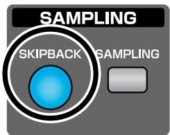
text_image
SAMPLING SKIPBACK SAMPLINGButton lit: Skip-back sampling can be performed in this state. Button unlit: Skip-back sampling cannot be performed. Not operating. You cannot use skip-back sampling if there is insufficient free memory.
Button blinking: Skip Back Sampling will be executed.
- Play the Fantom-G's keyboard or pads, or connect an instrument or some other device to the AUDIO IN jacks or DIGITAL AUDIO IN and input sounds or phrases.
2. Press [SKIPBACK].
Skip Back Sampling will be executed.
When Skip Back Sampling ends, the Sample Edit screen will appear (p. 266).
NOTE
Samples captured by Skip Back Sampling will be lost when you turn off the power. If you want to keep the sample, perform the Save procedure (p. 274).
MEMO
You can specify how far back sampling will occur when you perform skip-back sampling (5–40 seconds). With the factory settings this is set to 10 seconds (“Skip Back Time” (p. 302)).
This section explains how you can edit a sample that you sampled/imported.
Editing is performed in sample memory—a memory area dedicated to samples.
* You cannot execute this with more than one sample selected.
Selecting a Sample (Sample List)
Select a sample from the list.
Selecting a Sample
1. Press [SAMPLE] twice.
![ROLAND FANTOM G8 - Press [SAMPLE] twice. - 1](/content/2025/01/130804/images/df693bb6adae594eb3929dad4ea60857ccb35ef80ec3b43c5c29701f012f0855.jpg)
text_image
PATCH SONG SAMPLE ECTS (OUTING)The Sample List display appears.
![ROLAND FANTOM G8 - Press [SAMPLE] twice. - 2](/content/2025/01/130804/images/7674065cc1561d9c076741bd2bf67423ac7583c6f5f0458266a679838e26e49d.jpg)
text_image
Sample List Number Sample Name Ch Size Fk L/2000 0001 G Snap/0001 STREDO 0002 G Snap/0002 STREDO 0003 G Snap/0003 STREDO 0004 G Snap/0004 STREDO 0005 G Snap/0005 STREDO 0006 G Snap/0006 STREDO 0007 EMPTY 0008 EMPTY 0009 EMPTY 0010 EMPTY 0011 EMPTY 0012 EMPTYF-key operations in the Sample List screen
| F-key | Explanation | Page | |
| F1Load | Loads a sample from the project into memory. | p. 264 | |
| F2Save | Saves the selected sample to the project. | p. 274 | |
| F3Util Menu | Save All | Saves all samples. | p. 274 |
| Load All | Loads all samples | p. 264 | |
| Delete Sample | Deletes the sample from the project. | p. 265 | |
| Unload | Deletes the sample from memory. | p. 264 | |
| F4Mark | Adds a check mark to each sample | p. 263 | |
| F5Mark All | Adds check marks to all samples in the list | p. 263 | |
| F6Exit | Returns to the previous screen. | - | |
| F7Preview | Auditions the selected sample. | - | |
| F8Sample Edit | Displays the edit screen for the selected sample. | p. 266 | |
2. Use VALUE dial, [INC] [DEC], or ▲ ▼ to select a sample.
If you hold down [SHIFT] while you operate the above buttons, the sample number will change in steps of ten.
You can press [F7 (Preview)] to audition the selected sample.
3. Press [F8 (Sample Edit)].
The Sample Edit Screen appears. (p. 266)
The sample list shows the current state of the samples.
| Sample name | Indicates the name of the sample. Sample for which this field indicates “EMPTY” have not been loaded into memory. Load them if necessary. |
| Indicates whether the file exists in the project. Samples for which the “☐” symbol is not shown have not been saved, and will be lost when you turn off the power. Save them if necessary. | |
| Indicates that the sample has been edited. Your edits will be lost when you turn off the power. Save the sample if necessary. |
MEMO
By pressing [F4 (Mark)] or [F5 (Mark All)], you can add marks to the list, allowing you to perform operations (such as Delete or Import) on multiple samples in a single operation.
- If you want to select multiple samples, press [F4 (Mark)] to add a check mark to each sample you want to select.
- If you select a marked sample and press [F4 (Mark)], the check mark will be removed.
- If you press [F5 (Mark All)], a check mark will be added to all samples in the list.
- If you press [F5 (Mark All)] when all samples in the list already have a check mark, the check marks will be cleared from all samples.
Loading a Sample (Load)
Here's how you can load a sample from the project into sample memory.
- Press [SAMPLE].
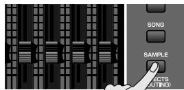
The Sample Edit screen will appear.
- Press [F1 (Sample List)].
The Sample List display appears.
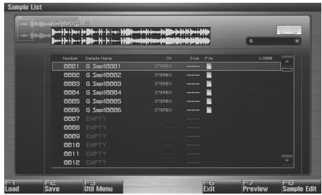
text_image
Sample List GSPID001 G SempID001 GSPID002 G SempID003 G SempID004 G SempID005 G SempID006 EMPTY EMPTY EMPTY EMPTY EMPTY EMPTY F1 Load F2 Save F3 Util Menu F6 Exit F7 Preview F8 Sample Edit-
Use VALUE dial, [INC] [DEC], or ▲ ▼ to select a sample.
-
Press [F1 (Load)].
A message will ask you for confirmation.
- Press [F7 (OK)] to execute.
To cancel, press [F8 (EXIT)].
Loading All Samples (Load All)
Here's how you can load all samples from the project into sample memory.
- Press [SAMPLE].
The Sample Edit screen will appear.
- Press [F1 (Sample List)].
The Sample List display appears.
- Press [F3 (Util Menu)].
The Sample Utility Menu window will appear.
- Press ▲ or ▼ to select "Load All," and then press [F8 (Select)].
To cancel, press [F7 (Cancel)].
A message will ask you for confirmation.
- Press [F7 (OK)] to execute.
To cancel, press [F8 (EXIT)].
Unloading a Sample (Unload)
This operation erases (unloads) the sample from sample memory. The sample file itself that is saved in the project will not be deleted.
- Press [SAMPLE].
The Sample Edit screen will appear.
- Press [F1 (Sample List)].
The Sample List display appears.
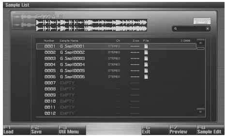
text_image
Sample List GAM205 Number Sample Name Ch Size F/Fy 1/2008 0001 G Smp10001 STREEO ---- 0002 G Smp10002 STREEO ---- 0003 G Smp10003 STREEO ---- 0004 G Smp10004 STREEO ---- 0005 G Smp10005 STREEO ---- 0006 G Smp10006 STREEO ---- 0007 EMPTY ---- 0008 EMPTY ---- 0009 EMPTY ---- 0010 EMPTY ---- 0011 EMPTY ---- 0012 EMPTY -----
Use VALUE dial, [INC] [DEC], or ▲ ▼ to select a sample.
-
Press [F3 (Util Menu)].
The Sample Utility Menu window will appear.
- Press ▲ or ▼ to select "Unlode," and then press [F8 (Select)].
To cancel, press [F7 (Cancel)].
A message will ask you for confirmation.
- Press [F7 (OK)] to execute.
To cancel, press [F8 (EXIT)].
Deleting a Sample (Delete)
This operation completes deletes the sample saved in the project, along with its file.
1. Press [SAMPLE].
![ROLAND FANTOM G8 - Press [SAMPLE]. - 1](/content/2025/01/130804/images/111b553824cb7de4e686a620b3aaae92dbcd7b24bcb717934bc4cd4a9ffcffa2.jpg)
The Sample Edit screen will appear.
2. Press [F1 (Sample List)].
The Sample List display appears.
![ROLAND FANTOM G8 - Press [F1 (Sample List)]. - 1](/content/2025/01/130804/images/7a0dbb97392e7c00f67a794514e5a26a549092be793e1cd078bba4bb9b5ebe27.jpg)
text_image
Sample List SAMPLES 1/2000 Number Sample Name On Size Exit 0001 G Smp10001 STREDO 0002 G Smp10002 STREDO 0003 G Smp10003 STREDO 0004 G Smp10004 STREDO 0005 G Smp10005 STREDO 0006 G Smp10006 STREDO 0007 EMPTY 0008 EMPTY 0009 EMPTY 0010 EMPTY 0011 EMPTY 0012 EMPTY- Use VALUE dial, [INC] [DEC], or ▲ ▼ to select a sample.
4. Press [F3 (Util Menu)].
The Sample Utility Menu window will appear.
- Press ▲ or ▼ to select "Delete Sample," and then press [F8 (Select)].
To cancel, press [F7 (Cancel)].
A message will ask you for confirmation.
6. Press [F7 (OK)] to execute.
To cancel, press [F8 (EXIT)].
Importing an Audio File (WAV/AIFF) from Your Computer
Audio files (WAV/AIFF) from your computer can be imported into memory as samples.
"Importing Audio file (Import Audio)" (p. 287)
Displaying Sample Edit Screen (Sample Edit)
1. Press [SAMPLE].
The Sample Edit screen will appear.
![ROLAND FANTOM G8 - Press [SAMPLE]. - 1](/content/2025/01/130804/images/84d8532be8a8ff028e5a30ced1502c1b620c053976c1651e4622cb8fa45801db.jpg)
text_image
Sample Edit SAMPLE EDIT 8801 (C 5mp8801) Start Point 88888888 Loop Start 88888888 End Point 88845648 Zoom Horz 1/256 Zoom Vert x1 Original Key 8BC 4) BPM J=120.00 Sample Set: +0.001 Sample List Param Modify F4 F5 F6 F7 F8 Preview ExitNOTE
Samples that you edit will be lost when you turn off the power. If you want to keep them, you must Save them (p. 274).
F-key operations in the Sample Edit screen
| F-key | Explanation | Page | |
| F1Sample List | Shows the sample list. | p. 263 | |
| F2Param | Displays the Sample Parameter screen, where you can make various settings for the sample. | p. 268 | |
| F3Modify | Truncate | Cuts an unwanted portion | p. 269 |
| Emphasis | Boosts/limits the high frequency range | p. 269 | |
| Normalize | Maximizes the volume | p. 270 | |
| Amp | Applies a volume envelope | p. 270 | |
| Time Stretch | Stretches/shrinks the sample | p. 271 | |
| Chop | Divides the sample | p. 272 | |
| F4Beat ◀ | Specifies the start/end point of the sample in units of a beat. | p. 267 | |
| F5Beat ▶ | Specifies the start/end point of the sample in units of a beat. | p. 267 | |
| F6Zoom | Zooms the waveform display. | p. 266 | |
| F7Preview | Auditions the selected sample. | - | |
| F8Exit | Returns to the previous screen. | - | |
Parameters in the Sample Edit screen
| Parameter | Explanation | Page |
| Start Point | The point at which playback will start. | p. 267 |
| Loop Start | The point at which loop playback (second time and onwards) will start. | p. 267 |
| End Point | The point at which playback will end. | p. 267 |
| Zoom Horz | The magnification (horizontal axis) of the display. | p. 266 |
| Zoom Vert | The magnification (vertical axis) of the display. | p. 266 |
| Original Key | Note number that will play the sample at the pitch at which it was sampled. | p. 268 |
| BPM | Specifies the original tempo of the sample. | p. 268 |
| Sample Gain | Adjusts the gain of the sample. | p. 268 |
Magnifying/Shrinking the Waveform Display (Zoom)
Here's how to change the magnification of the sample display.
1. In the Sample Edit screen, press [F6 (Zoom)].
The Zoom window will appear.
2. Use [CURSOR] to change the magnification of the display.
• Horizontal axis (time axis): 1/1–1/65536
Press ▶ to increase the display magnification.
Press ◀ to decrease the display magnification.
• Vertical axis (waveform amplitude axis): x1–x128
Press ▲ to increase the display magnification.
Press ▼ to decrease the display magnification.
3. Press [F8 (Close)] to close the window.
Even without displaying the Zoom window, you can press ◀ to expand/shrink the horizontal axis, or hold down [SHIFT] and press ▲ ▼ to expand/shrink the vertical axis.
Setting the Start/End Points of the Sample
You can specify the portion of the sample that will actually sound. You can also specify the region that is to be looped.
1. Select the sample you want to edit, and access the Sample Edit screen.
* For details on how to select a sample, refer to “Selecting a Sample” (p. 263).
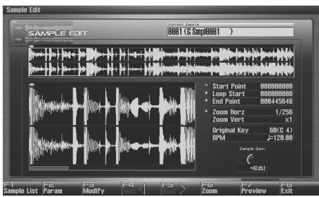
text_image
Sample Edit 0001 (G Smp8991 ) Sample List Param Modify F4 F5 F6 Zoom Preview Exit Start Point 00000000 Loop Start 00000000 End Point 00045648 Zoom Horz 1/250 Zoom Vert x1 Original Key 60°C 47 BPM J=126.88 Sample Data +65.632. Use ▲ or ▼ to select the point that you want to set.
- Start Point:
This is the point at which playback will start. Set this so that any unwanted portion at the beginning of the sample will be skipped, and the sound will begin at the desired moment.
- Loop Start:
This is the point at which loop playback (second and subsequent times) will start. Set this if you want to loop the sound from a point other than the start point.
- End Point:
This is the point at which playback will end. Set this so that any unwanted portion at the end of the sample will not be heard.
MEMO
By pressing [F7 (Preview)] you can audition the region between the start point and end point.
MEMO
If you hold down [F7 (Preview)] and edit the start/loop/end point, the sample will play repeatedly across that point. Since the sound in the region you're specifying will play repeatedly, this is a convenient way to check your setting.
(Zooming-in or zooming-out on the waveform will change the region that loops.)
3. Either turn the VALUE dial or use [INC], [DEC] to move the point so it's where you want it to be.
You'll probably find it convenient to zoom-in when making fine adjustments, and zoom-out when making major adjustments (p. 266).
You can move the point in units of one beat by pressing [F4]
(Beat ◀) or [F5 (Beat ▶)].
MEMO
After specifying the start point and end point, you can execute Truncate (p. 269) to delete unwanted portions at the beginning and end of the sample.
About the beat
Samples contain beat data. Up to 100 beat locations are specified for one sample. If the sample contains more than 100 beats, fifty beat locations will be specified from the beginning and end of the sample, respectively.
When you want to reset the beat indication (Reset Grid function [F7 (Reset Grid)])
From the Sample Edit screen, specify the start point of the sample, press [F2 (Sample Param)] to access the Sample Prm screen, specify the BPM, and then press [F7 (Reset Grid)]. This will reapply the grid to the sample according to the start point and BPM you specified. To execute, press [F8 (Execute)].
NOTE
Sample modify menu operations (Chop, Normalize, etc.) apply to the entire sample. Even if you specify a start point or end point, they will be ignored. If you want to apply the operation only to the region between the start point and end point, use Truncate to delete unwanted portions of the sample, and then perform the sample modify menu operation.
Using the Knobs to Edit the Points
You can use the knobs to edit each point. Using the knobs is convenient when you need to make large changes to the value.
1. Use the CONTROL knobs to specify the following editing points.
From the left, the knobs have the following functions.
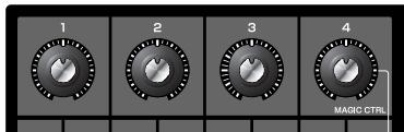
text_image
1 2 3 4 MAGIC CTRL- : Start Point
E1 : Loop Start
EL : End Point
- : Zoom-in/zoom-out the horizontal axis of the display
Making Settings for Sample (Sample Parameters)
Here you can make various settings for the sample.
-
Select the sample that you want to edit (p. 263).
-
Press [SAMPLE] to access the Sample Edit screen, and press [F2 (Param)].
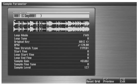
text_image
Sample Parameter Current Sample 0001 (G Smpl0001 ) Loop Mode FW0 Loop Tune 0 Original Key 68CC 4) BPM J=120.00 Time Stretch Type TYPE01 Start Fine 0 Loop Start Fine 0 Loop End Fine 0 Sample Gain *6[Gdb] Sample Fine Tune 0 Sample Level 127 F8 F7 FB Reset Grid Preview Exit-
Press ▲ or ▼ to select a parameter.
-
Use VALUE dial or [INC], [DEC] to edit the value.
- Loop Mode
Specifies how the sample will be played.
Value
FWD (Forward):
After the Sample played back from the Start point to the End point, it will then be repeatedly played back in the forward direction, from the Loop Start point to the End point.
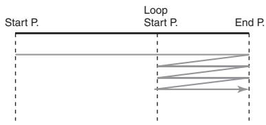
flowchart
graph LR
    A["Start P."] --> B["Loop Start P."]
    B --> C["End P."]
    style A fill:#f9f,stroke:#333
    style B fill:#ccf,stroke:#333
    style C fill:#cfc,stroke:#333
ONE-SHOT:
The sample will be played back only once, from the Start point to the End point.
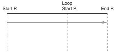
flowchart
graph LR
    A["Start P."] --> B["Loop Start P."]
    B --> C["End P."]
REV (Reverse):
When the sample has been played back from the End point to the Start point, it will be repeatedly played back in the reverse direction, from the Loop Start point to the Start point.
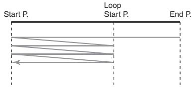
flowchart
graph TD
    A["Start P."] --> B["Loop Start P."]
    B --> C["End P."]
    style A fill:#f9f,stroke:#333
    style B fill:#ccf,stroke:#333
    style C fill:#cfc,stroke:#333
REV-ONE (Reverse One-shot):
The sample will be played back only once from the End point to the Start point in the reverse direction.
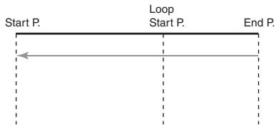
flowchart
graph LR
    A["Start P."] --> B["Loop Start P."]
    B --> C["End P."]
- Loop Tune
Specifies the pitch of the loop region.
Value: -50- +50
* Make fine adjustments in one-cent (1/100 semitone) increments.
- Original Key
Note number that will play the sample at the pitch at which it was sampled.
Value: 0 (C-1)-127 (G9)
- BPM (TEMPO)
Specifies the original tempo of the sample.
When setting the BPM (tempo) value, you can hold down [SHIFT] and turn the VALUE dial, or use [INC] [DEC] to adjust the value to the right of the decimal point.
Value: 5.00–300.00
* In order to synchronize the tempo, Wave Temp Sync (p. 92) must be turned on.
- Time Stretch Type
Specifies how the tempo will be synchronized. Decreasing this value will optimize the sound for more rapid phrases, and increasing this value will optimize the sound for slower phrases.
Value: TYPE01-TYPE10
- Start Fine
Fine adjustment of the Start point.
Value: 0–255
- Loop Start Fine
Fine adjustment of the Loop Start point.
Value: 0–255
- Loop End Fine
Fine adjustment of the End point.
Value: 0–255
- Sample Gain
This adjusts the gain of the sample, letting you boost the volume if it decreased in the process of sampling.
Value: 0, +6, +12 [dB]
- Sample Fine Tune
This adjusts the pitch of the sample in steps of one cent (over a range of +/-50 cents).
Value: -50- +50
* 1 cent = 1/100th of a semitone
- Sample Level
This adjusts the volume of the sample.
Value: 1–127
* By pressing [F7 (Reset Grid)] you can reassign the sample grid according to the specified start point and BPM. To execute, press [F8 (Execute)].
- Press [EXIT] when you are finished.
Sample BPM calculation function
Calculates the BPM (tempo) of the sample.
- Access the Sample Parameter screen.
- Press [F5 (BPM Calc)] to open the BPM Calc window.
-
Enter the sample's length (Measure) and time signature (Beat).
-
Press [F8 (Execute)] to calculate the tempo and enter the value in the BPM field of the Sample Parameter screen.
Removing Unwanted Portions of a Sample (Truncate)
This operation cuts the portions of the sample that are earlier than the Start Point and later than the Loop End Point.
- Press [SAMPLE] to access the Sample Edit screen.
- Press ▲ or ▼ to select the parameter.
- Start Point: Specifies the sample start point.
• End Point: Specifies the sample end point.
- Either turn the VALUE dial or use [INC] [DEC] to set the value.
- Press [F3 (Modify)].
The Sample Modify Menu window will appear.
- Press ▲ or ▼ to select "Truncate," and then press [F8 (Select)].
To cancel, press [F7 (Cancel)].
- If you want to replace the current sample with the truncated sample, press [F6 (Over Write)].
- Press [F8 (Execute)].
A message will ask you for confirmation.
- Press [F7 (OK)] to execute.
To cancel, press [F8 (EXIT)].
MEMO
If [F6 (Over Write)] is off, pressing [F7 (OK)] to execute will create the edited sample in the lowest unused sample number in the list.
Boosting or Limiting the High-frequency Range of the Sample (Emphasis)
In some cases, the audio quality will be improved if you boost the high-frequency range of an imported sample. Also, the high-frequency range of the sample may be emphasized when you use a sampler made by another manufacturer. In this case, you can minimize the change in tonal character by attenuating the high-frequency range.
- Press [SAMPLE] to access the Sample Edit screen.
- Press [F3 (Modify)].
The Sample Modify Menu window will appear. -
Press ▲ or ▼ to select "Emphasis," and then press [F8 (Select)].
To cancel, press [F7 (Cancel)]. -
Either turn the VALUE dial or use [INC] [DEC] to select the emphasis type.
• PreEmphasis: Emphasizes the high-frequency range.
- DeEmphasis: Attenuates the high-frequency range.
-
If you want to replace the current sample with the emphasized sample, press [F6 (Over Write)].
-
Press [F8 (Execute)].
A message will ask you for confirmation.
- Press [F7 (OK)] to execute.
To cancel, press [F8 (EXIT)].
MEMO
If [F6 (Over Write)] is off, pressing [F7 (OK)] to execute will create the edited sample in the lowest unused sample number in the list.
Maximizing the Volume of a Sample (Normalize)
This operation raises the level of the entire sample as much as possible without exceeding the maximum level. In some cases, the volume of a phrase you resampled (p. 260) will be lower than the volume of the original phrase. In this case, it is a good idea to boost the volume by executing the Normalize operation.
- Press [SAMPLE] to access the Sample Edit screen.
- Press [F3 (Modify)].
The Sample Modify Menu window will appear. - Press ▲ or ▼ to select "Normalize," and then press [F8 (Select)].
To cancel, press [F7 (Cancel)]. - If you want to replace the current sample with the normalized sample, press [F6 (Over Write)].
- Press [F8 (Execute)].
A message will ask you for confirmation. - Press [F7 (OK)] to execute.
To cancel, press [F8 (EXIT)].
MEMO
If [F6 (Over Write)] is off, pressing [F7 (OK)] to execute will create the edited sample in the lowest unused sample number in the list.
Amp
This operation applies an envelope (time-variant change) to the volume of the sample. You can also adjust the volume of the entire sample.
- Press [SAMPLE] to access the Sample Edit screen.
- Press [F3 (Modify)].
The Sample Modify Menu window will appear. -
Press ▲ or ▼ to select “Amp,” and then press [F8 (Select)].
To cancel, press [F7 (Cancel)]. -
Use VALUE dial or [INC] [DEC] to set the value.
• Rate: Specifies the rate of volume boost.
This specifies how much boost will be applied relative to the current volume. The entire sample you select will be boosted.
Value: 0–400%
- If you want to specify a point, press [F5 (Point)] to light it into red. Press ▲ or ▼ to select a parameter, and then use VALUE dial or [INC] [DEC] to set the value.
- Current Point: Specifies the currently selected point. Beginning near the start point, the points will be numbered 1, 2, 3, or 4.
Value: 1–4
- Point 1–4: Location of the current point
- Rate 1–4: Amplification ratio of the current point Specifies how the volume of each point is to be boosted relative to the current value.
Value: 0–400%
-
If you want to replace the current sample with the normalized sample, press [F6 (Over Write)].
-
Press [F8 (Execute)].
A message will ask you for confirmation.
- Press [F7 (OK)] to execute.
To cancel, press [F8 (EXIT)].
MEMO
If [F6 (Over Write)] is off, pressing [F7 (OK)] to execute will create the edited sample in the lowest unused sample number in the list.
Stretching or Shrinking a Sample (Time Stretch)
This operation stretches or shrinks the sample to modify the length or tempo. You can stretch or shrink the sample by a factor of one half to double the original length.
-
Press [SAMPLE] to access the Sample Edit screen.
-
Press [F3 (Modify)].
The Sample Modify Menu window will appear.
- Press ▲ or ▼ to select "Time Stretch," and then press [F8 (Select)].
To cancel, press [F7 (Cancel)].
- Press ▲ or ▼ to select the parameter.
- Edit Time Stretch
VALUE
BPM: Changes the BPM of the sample to the BPM you specifies.
Time: Specifies the length of the sample as a time value.
Rate: Specifies the length relative to the current length of the sample.
Value: 50.0–200.0%
- Type
Lower settings of this value will make the sound more suitable for faster phrases, and higher settings will make the sound more suitable for slower phrases.
Value: TYPE01-TYPE10
- Quality Adjust
Make fine adjustments to the tonal quality of the Time Stretch.
Value: 1–10
- Use VALUE dial or [INC] [DEC] to specify the tempo/length.
When setting the BPM (tempo) value, you can hold down [SHIFT] and turn the VALUE dial, or use [INC] [DEC] to adjust the value to the right of the decimal point.
- Press [F8 (Execute)].
A message will ask you for confirmation.
- Press [F7 (OK)] to execute.
To cancel, press [F8 (EXIT)].
Dividing a Sample into Notes (Chop)
The chop function divides a sample waveform into separate notes.
* The Create Sample Set function makes it easy to create a sample set from the chopped samples.
Procedure for Dividing a Sample
You can freely specify the point(s) at which the sample is to be divided.
-
Press [SAMPLE] to access the Sample Edit screen.
-
Press [F3 (Modify)].
The Sample Modify Menu window will appear.
- Press ▲ or ▼ to select "Chop," and then press [F8 (Select)].
To cancel, press [F7 (Cancel)].
-
Press ▲ or ▼ to move the cursor to "Current Address."
-
Either turn the VALUE dial or use [INC] [DEC] to move the point.
-
At the location where you want to divide the sample, press [F4 (Add Point)].
The current location will be the dividing point.
- Repeat steps 5 and 6 to specify other dividing points as desired.
You can specify up to 15 locations at which to divide the sample; i.e., the sample will be divided into a maximum of 16 pieces.
- Audition the sample as described in the section "Auditioning the Divided Samples" (p. 273).
If you want to re-make settings, move or delete the point (p.273).
- Press [F8 (Execute)].
A message will ask you for confirmation.
- To execute the division, press [F7 (OK)].
To cancel, press [F8 (EXIT)].
When you execute the Chop operation, a message will ask whether you want to execute Create Sample Set.
* The divided samples will be added to the sample list.
- If you want to execute Create Sample Set, press [F8 (Execute)].
NOTE
When you execute Create Sample Set, any setting changes that you've made for a patch, rhythm set, or sample set will be lost.
MEMO
When you execute Create Sample Set, a sample set with the divided samples assigned to the pads will be automatically created.
- If you don't want to execute Create Sample Set, press [F7 (Cancel)].
Automatically Dividing a Sample (Auto Chop)
Here's how you can automatically specify the points at which the sample is to be divided, and then divide the sample.
-
Press [SAMPLE] to access the Sample Edit screen.
-
Press [F3 (Modify)].
The Sample Modify Menu window will appear.
- Press ▲ or ▼ to select "Chop," and then press [F8 (Select)].
To cancel, press [F7 (Cancel)].
-
Press [F6 (Auto Chop)].
-
Either turn the VALUE dial or use [INC] [DEC] to select the method by which the sample is to be divided.
- Chop Type
Specifies how the sample will be divided.
Value
Level: Divides according to volume.
Beat: Divides at beats based on the BPM (p. 268) of the sample.
Divide x: The sample will be divided into the specified number of equal-sized samples.
-
Press ▼.
-
Either turn the VALUE dial or use [INC] [DEC] to set the value.
• Level (If Chop Type is Level)
Level at which the sample is to be divided. Lower settings of this value will cause the sample to be divided more finely.
Value: 1–10
- Beat (If Chop Type is Beat)
Beat interval at which the sample is to be divided.
Value: 1/32, 1/16T, 1/16, 1/8T, 1/8, 1/4T, 1/4, 1/2, 1/1, 2/1
• Times (If Chop Type is Divide x)
Number of samples into which the sample is to be divided.
Value: 2–16
- Press [F8 (Execute)].
The sample will be automatically divided according to your settings, and the points will be specified. A maximum of 15 division points will be set (16 regions).
To cancel, press [F7 (Cancel)].
- Audition the sample as described in the section
"Auditioning the Divided Samples" (p. 273)
If you want to re-make settings, move or delete the point "Moving a Dividing Point" (p. 273).
- Press [F8 (Execute)].
A message will ask you for confirmation.
- To execute the division, press [F8 (Execute)].
* To cancel, press [F7 (Cancel)].
When you execute Auto Chop, a message will ask you whether you want to execute Create Sample Set.
- If you want to execute Create Sample Set, press [F8 (Execute)].
MEMO
When you execute Create Sample Set, a sample set with the divided samples assigned to the pads will be automatically created.
- If you don't want to execute Create Sample Set, press [F7 (Cancel)].
You will return to the Sample Edit screen.
Auditioning the Divided Samples
After dividing the sample, you can press the pads to audition each of the divided samples.
From the sample nearest to the start point, the samples will be played by pads [1], [2],...[16].
Moving a Dividing Point
-
Press ▲ or ▼ to move the cursor to "Point No."
-
Turn the VALUE dial to select the point that you want to move.
In order from the start point, the points are numbered 1, 2,...15.
-
Press ▼.
-
Turn the VALUE dial to move the dividing point.
Deleting a Dividing Point
-
Press ▲ or ▼ to move the cursor to "Point No."
-
Turn the VALUE dial to select the point that you want to delete.
-
Press [F5 (Clear Point)].
The dividing point will be deleted.
Saving a Sample (Save)
Here's how to save the selected sample into the project.
A newly loaded sample, as well as any changes you've made in the settings for a sample will be lost as soon as you turn off the power. If you want to keep such data, you must save it as follows.
- Press [SAMPLE].
- Press [F1 (Sample List)].
The Sample List display appears.
Samples without the “☐” symbol and samples with the “√” symbol have not been saved.
-
Use VALUE dial, [INC] [DEC], or ▲ ▼ to select the sample that you want to save.
-
Press [F2 (Save)].
-
Assign a name to the sample.
For details on assigning names, refer to “Assigning a Name” (p. 42)
- When you have finished inputting the name, press [F8 (OK)].
A screen will appear allowing you to select the write-destination sample.
-
Turn the VALUE dial, or use [INC] [DEC] to select the sample number.
-
Press [F8 (Write)].
A message will ask you for confirmation.
Never switch off the Fantom-G while data is being saved.
- Press [F7 (OK)] to execute the save operation.
To cancel the operation, press [F8 (EXIT)].
- You can't save by overwriting another sample.

You can also save a sample by pressing the [WRITE] button to access the WRITE MENU, and then choosing "Sample."
Saving all samples (Save All)
Here's how to save all samples of the sample list into the project.
- Press [SAMPLE].
- Press [F1 (Sample List)].
The Sample List display appears.
Samples without the “☐” symbol and samples with the “☐” symbol have not been saved.
- Press [F3 (Util Menu)].
The Sample Utility Menu window will appear.
- Press ▲ or ▼ to select "Save All," and then press [F8 (Select)].
To cancel, press [F7 (Cancel)].
A message will ask you for confirmation.
- Press [F7 (OK)] to execute.
To cancel, press [F8 (EXIT)].

When you execute Save All, the samples will be written in the same numerical order as they appear in the sample list. The sample names will be assigned automatically.
Creating a multisample
A “multisample” is a set of different samples assigned to the notes of the keyboard. One multisample can split up to 128 samples across the keyboard. You can store 128 multisamples in user memory.
* In order to hear a multisample, you must assign it to a patch.
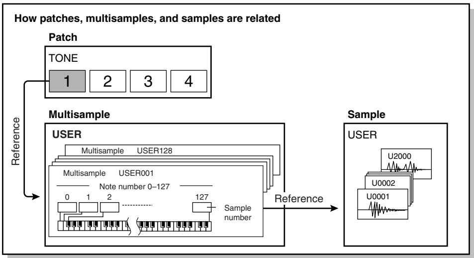
flowchart
graph TD
    A["Patch"] --> B["TONE"]
    B --> C["1"]
    B --> D["2"]
    B --> E["3"]
    B --> F["4"]
    G["Multisample"] --> H["USER"]
    H --> I["Multisample USER128"]
    I --> J["Multisample USER001"]
    J --> K["Note number 0-127"]
    K --> L["Sample number"]
    L --> M["Sample"]
    M --> N["U2000"]
    M --> O["U0002"]
    M --> P["U0001"]
    style A fill:#f9f,stroke:#333
    style G fill:#ccf,stroke:#333
    style H fill:#cfc,stroke:#333
    style I fill:#fcc,stroke:#333
    style J fill:#cff,stroke:#333
    style K fill:#ffc,stroke:#333
    style L fill:#cfc,stroke:#333
    style M fill:#fcc,stroke:#333
Creating a multisample in the Patch Edit screen
- Select the patch that you want to edit.
MEMO
You should start by initializing the patch settings. (p. 87)
MEMO
You can't create a multisample if the patch type is "Rhythm" or "Sample Set."
- Press [PATCH] twice to get the Patch Pro Edit screen.
- Press [F1 (↑)] or [F2 (↓)] to select "Wave."
- Set the parameters as follows to assign the multisample to the desired Tone 1–4.
• Wave Group: MSAM (Multisample waveforms)
• Wave Number. L (Mono): Multisample number
* For details on making this setting, refer to How to Make Patch Settings (p. 84).
* If you want to use a stereo multisample, specify the same number for L and R.
- Press [F4 (Util Menu)].
The Song Utility Menu window will appear.
- Use ▲ / ▼ to choose “Multisample Edit,” and press [F8 (Select)].
The Multisample Edit window will appear.
- Edit the multisample.
* For details on editing, refer to “Editing a multisample” (p. 276).
8. Save the multisample.
* In the Multisample Edit screen, press [WRITE] and save the multisample as directed by the screen that appears.
9. Save the patch.
* For details on how to save the patch, refer to Saving Patches You've Created (Write) (p. 88).
Editing a multisample
About the Multisample Edit screen
Multisample Edit Screen
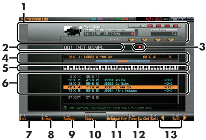
text_image
1 Ultisample Edit 1:0 1:000 PATCH Tone Select Current Tone PART 1 PART 2 Patch Integration Part 1 PART 3 001-Grand ALL Tone Switch 2 001: INIT MSMPL 3 60(C 4) U0003 0 Yea 3x 60(C 4) 4 5 6 0(C -) 35(B 1) 36(C 2) 47(B 2) U0001 ahuha 48(C 3) 59(B 3) U0002 Do Baby 60(C 4) 71(B 4) U0003 0 Yea 3x 72(C 5) 83(B 5) U0004 Aint Nobody MONO MONO MONO 97(C87) 127(G 9) ISHFT,(VALUE),(INC/DEC),(+/-) = Select Note, (+/-) = Select Zone. F1 F2 F3 F4 F5 F6 F7 F8 List Assign Copy Original Key Tone Sw/Sel Split Split 7 8 9 10 11 12 13- Shows information about the patch.
- Shows the name of the multisample.
- Indicates whether the multisample has been edited.
- Shows information about the current note.
- Indicates the original key of the sample.
- Shows a list of the samples assigned to the multisample.
- Changes the multisample assigned to a tone (p. 277).
- Erases the data from the selected region of notes (p. 277).
- Assigns a sample to the selected region (p. 277).
- Copies a sample from a key to another key (p. 277).
- Specifies the original key of the sample (p. 278).
- Opens the Tone Switch/Select window (p. 277).
- Moves the split point (p. 277).
If you hold down [SHIFT]
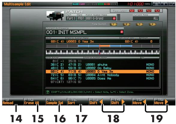
text_image
Multisample Edit PATCH Part | Part1 | PAST | 0001-C-Brand Zone Select 12 23 34 Current Tone ALL Tone Switch 2 3 4 CurrentMultiSample 001: INIT MSMPL Noise Select Sample Number/Noise 68(C 4) U0003 0 Yea 3x 68(C 4) 0(C -) 35(B 1) 36(C 2) 47(B 2) U0001 ahuha 48(C 3) 59(B 3) U0002 Oo Baby 68(C 4) 71(B 4) U0003 0 Yea 3x 72(C 5) 83(B 5) U0004 Aint Nobody 84(C 6) 86(C 7) U0005 Does Me 97(C87) 127(G 9) SHIFT,VALUE,INC/DEC,[+/-] * Select Note, [+/-] * Select Zone. F9 F10 F11 F12 F13 F14 F15 F16 Reload Erase All Sample Sel Sort Shift Shift Move Move 14 15 16 17 18 19- Returns a multisample to the last-written state (p. 277).
- Erases all notes (p. 278).
- Assigns a sample to the current zone (p. 278).
- Sorts samples in a multisample in the order of their original key (p. 278).
- Moves all samples to left or right (p. 278).
- Moves the data of the current zone to left or right (p. 278).
Selecting the notes to edit
1. Press the keyboard to select the sample you want to edit.
You can select a region by pressing two notes.
MEMO
You can also make your selection by turning the VALUE dial,
by using ◀ ▶, or by using [INC][DEC]. In this case, hold down [SHIFT] to select a region of notes.
Changing the multisample assigned to a tone (List)
Here's how you can change the multisample that's assigned to the current tone.
1. In the Multisample Edit screen, press [F1 (List)].
The Multisample List window will open.
The buttons have the following functions.
- VALUE dial, ▲ ▼ , [INC][DEC] Change the number of the multisample to be assigned.
- [F7 (Cancel)] or [EXIT] Cancel the operation and return to the previous screen.
- [F8 (Select)] Assigns the selected multisample to the current tone, and return to the previous screen.
Erasing the data from the selected region of notes (Erase)
1. In the Multisample Edit screen, press [F2 (Erase)].
The data for the selected region of notes will be erased.
Assigning a sample to the selected region (Assign)
1. In the Multisample Edit screen, press [F3 (Assign)].
The Sample List window will appear, allowing you to assign the selected sample to the selected region.
The buttons have the following functions.
• [F6 (Preview)]
Auditions the sample.
• [F7 (Exit)] or [EXIT]
Cancel the operation and return to the previous screen.
• [F8 (Select)] or [ENTER]
Selects the sample and return to the Multisample Edit screen.
Copying a sample from a key to another key (Copy)
Here's how the sample assigned to a note can be copied to a different note of the keyboard.
1. In the Multisample Edit screen, press the key to which the copy-source sample is assigned.
You can also select the note by using VALUE dial, ▲ ▼ , or [INC][DEC].
The Sample Data area shows information about the sample assigned to the current note.
2. Press [F4 (Copy)] so it lights in red.
3. Press the copy-destination key.
If you specify a region by pressing more than one key, the data will be copied to the region between the lowest and highest keys you press.
4. Take your hand off the keyboard.
[F4 (Copy)] will go dark, and you will return to the normal Multisample Edit screen.
Opening the Tone Switch/Select window (Tone Sw/Sel)
- In the Multisample Edit screen, press [F6 (Tone Sw/Sel)]. The Tone Switch/Select window will open.
This is the same as when you press [F8 (Tone Sw/Sel)] in the Single Play screen.
2. Press [EXIT] to close the window.
Moving the split point (Split Point)
The "Split Point" is the boundary between zones (p. 278).
1. In the Multisample Edit screen, press [F7 (Split⇐)][F8 (Split⇒)].
The split point of the selected sample and the adjacent sample will move to left or right.
Returning a multisample to the last-written state (Reload)
Here's how you can return the currently edited multisample to the state in which it was last written.
1. In the Multisample Edit screen, hold down [SHIFT] and press [F1 (Reload)].
A screen will ask you for confirmation.
2. Press [F7 (OK)].
If you decide to cancel, press [F8 (CANCEL)].
Erasing all notes (Erase All)
Here's how to erase all notes.
- In the Multisample Edit screen, hold down [SHIFT] and press [F2 (Erase All)].
A screen will ask you for confirmation.
- Press [F7 (OK)].
If you decide to cancel, press [F8 (CANCEL)].
Replacing the sample of the current zone (Sample Select)
A “zone” is a region to which the same sample is assigned. Here’s how to assign a sample to the currently selected zone (the “current zone”).
- In the Multisample Edit screen, hold down [SHIFT] and press [F3 (Sample Select)].
The Sample List window will appear, allowing you to assign the selected sample to the current zone.
The buttons have the following functions.
• [F7 (EXIT)] or [Exit]
Cancel the operation and return to the previous screen.
• [F6 (Preview)]
Auditions the sample.
• [F8 (Select)] or [ENTER]
Selects the sample and return to the Multisample Edit screen.
Specify the original key (Original Key) of the sample
Samples you record or import are set so that they will play at their original pitch when you press the C4 note.
In order to correctly match the key of the sample to the keyboard, you must modify the “original key” of the sample.
For example, if you sampled a sound whose pitch was E4, you'll need to change its "original key" setting to E4 so that it will play at its original pitch when you press the E4 note of the keyboard.
* A sample will not play more than two octaves higher than its original key.
- In the Multisample Edit screen, press [F5 (Original Key)].
The Sample Original Key window will open.
The buttons have the following functions.
• VALUE dial, [INC][DEC]
Change the original key of the sample assigned to the current note.
• [F7 (Preview)]
The sample will play at its current original key while you continue holding down the button.
• [F8 (Close)]
Closes the Sample Original Key window.
- Keyboard
When you play the keyboard, the original key of the sample assigned to the most recently pressed note will be displayed.
- Save the sample whose original key you changed.
* For details on saving a sample, refer to Saving a Sample (Save) (p. 274).
Sorting samples in the order of their original key (Sort)
This operation reassigns all samples currently assigned to the multisample, so that they are placed in the order of their original key setting. (This produces the same result as Create Multisample.)
- In the Multisample Edit screen, hold down [SHIFT] and press [F4 (Sort)].
A screen will ask you for confirmation.
- Press [F7 (OK)].
If you decide to cancel, press [F8 (CANCEL)].
Moving all samples to left or right (Shift)
Here's how all samples assigned to notes can be shifted to the left or right.
- In the Multisample Edit screen, hold down [SHIFT] and press [F5 (⇐)][F6 (⇒)].
Moving the data of the current zone to left or right (Move)
Here's how the sample of the current zone can be moved to left or right.
- In the Multisample Edit screen, hold down [SHIFT] and press [F7 (⇐)][F8 (⇒)].
08: Various Settings (Menu and System)
This chapter explains the menus and system settings.
- Menu Reference......p. 280
- System Settings....p. 290
• V-LINK p. 305
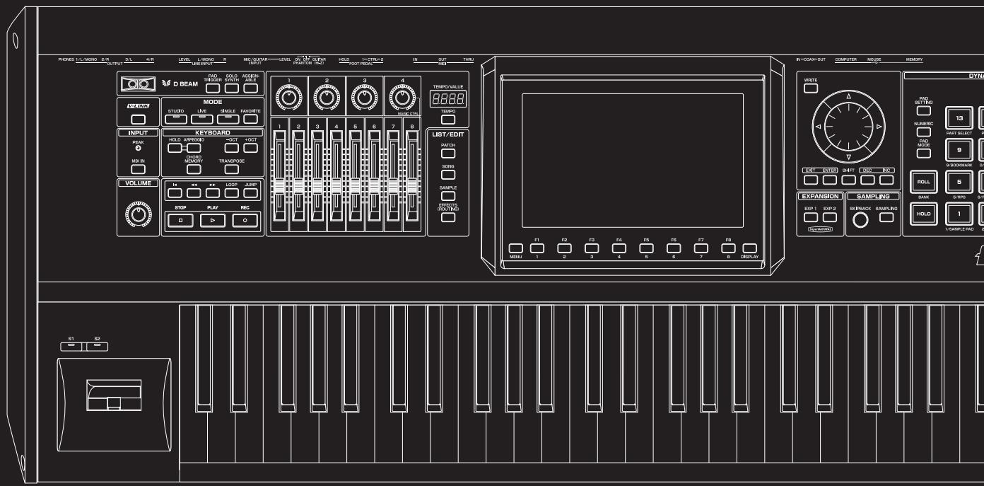
text_image
PROKES L/L MISO 2/R OUTPUT 3/L 4/R LEVEL L-MISO 5 MECUTAIN LEVEL 6 M.1.2 GURAN HOLD I-CTR=2 IN OUT TURU D BEAM RAD TRIGGER SWORD ASSEMB- MODE STUDIO LIVE SINGLE FAUCERS INPUT PEAK HOLD APPROX 3OCT 4OCT CHORD MEOCON TRANSPOSE VOLUME STOP PLAY REC LIST/EDIT MATCH DOYS SAMPLE CAPSIC (RDT/RDS) EXPANSION SAMPLING EXP 1 EXP 2 SREBACK SAMPLING HOLD 1 SAMPLE RAD 2 S1 SB MINI 1 2 3 4 5 6 7 8 DISPLAY IN-COMP-OUT COMPUTER MOUSE MEMORY WIFE PAD SETTING FLAVENIX 13 FAST SELECT 9 BLOODMARK ON ROLL 5 SANK 6-RP0 6-RP1 F1 F2 F3 F4 F5 F6 F7 F8 S1 SBMenus
The menus contain various functions you will find helpful when using the Fantom-G.
Press [MENU] to access the menu, select the desired function, and execute it.
| Menu name | Explanation | Page |
| Project | Load or save a project | p. 280 |
| System | Access the System Setting screen | p. 290 |
| Factory Reset | Reset the Fantom-G to the factory-set condition | p. 284 |
| Format USB Memory | Formats (initializes) USB memory | p. 284 |
| USB Storage | Connects the Fantom-G to a computer and mounts the internal memory as USB memory | p. 285 |
| Import Audio | Imports a WAV/AIFF format audio file into the Fantom-G | p. 289 |
Project-related Settings (Project)
Here's how to load a project from internal memory or USB memory into the Fantom-G's temporary area, or save the project from the Fantom-G's temporary area.
Load Project
This operation will load a project from internal memory or USB memory into the Fantom-G's temporary area.
NOTE
When you load a project, the contents of the temporary area will be rewritten. If the temporary area contains important data, you must save it to internal memory or USB memory before loading a project.
- Press [MENU] to access the Menu window.
- Turn the VALUE dial or use [CURSOR] to choose "Project," and then press [ENTER].
The Project Menu will appear. - Turn the VALUE dial or use [CURSOR] to choose "Load Project," and then press [F8 (Select)].
MEMO
You can also press [F1 (Load)] to execute this.
-
Press [F1 (Internal)] or [F2 (USB Memory)] to select the load-source area (internal memory or USB memory).
-
Use ▲ or ▼ to select the project that you want to load.
-
Press [F8 (Load)].
A confirmation message will appear.
- Press [F7 (OK)] to execute.
* If you decide to cancel, press [F8 (EXIT)].
Save Project
This operation will save the project from the temporary area to internal memory or USB memory.
- Press [MENU] to access the Menu window.
- Turn the VALUE dial or use [CURSOR] to choose "Project," and then press [ENTER].
The Project Menu will appear. - Turn the VALUE dial or use [CURSOR] to choose "Save Project," and press [F8 (Select)].
MEMO
You can also press [F2 (Save)] to execute this.
A confirmation message will appear.
- Press [F7 (OK)] to execute.
* If you decide to cancel, press [F8 (EXIT)].
MEMO
If an error message appears
An error message may appear if the data cannot be successfully saved, such as when there is insufficient space in internal memory or USB memory.
"Error Messages" (p. 322) lists the various errors that may appear, and explains the appropriate response.
Save As Project
This operation will save the project from the temporary area to internal memory or USB memory under a different name.
- Press [MENU] to access the Menu window.
- Turn the VALUE dial or use [CURSOR] to choose "Project," and then press [ENTER].
The Project Menu will appear. - Turn the VALUE dial or use [CURSOR] to choose "Save As Project," and press [F8 (Select)].
MEMO
You can also press [F3 (Save As)] to execute this.
-
Press [F1 (Internal)] or [F2 (USB Memory)] to select the save-destination area (internal memory or USB memory).
-
Press [F8 (Save As)].
-
The Project Name window will appear. Enter a name, and press [F8 (OK)].
MEMO
If you selected internal memory, there will be no step for entering a name.
cf.
For details on how to enter a name, refer to “Assigning a Name” (p. 42).
A confirmation message will appear.
- Press [F7 (OK)] to execute.
* If you decide to cancel, press [F8 (EXIT)].
MEMO
If an error message appears
An error message may appear if the data cannot be successfully saved, such as when there is insufficient space in internal memory or USB memory.
"Error Messages" (p. 322) lists the various errors that may appear, and explains the appropriate response.
Create Project
This operation will create a new project.
When you execute a factory reset, preload data is loaded into the User Patch and User Live / Studio Set areas. If you don't need the preload data, choose internal memory when executing Create Project. This allows you to create a project in which all data is initialized.
NOTE
If you create a new project by selecting the internal memory, the user project that is inside the Fantom-G will be overwritten (erased). If you have important data, please backup to USB memory.
- Press [MENU] to access the Menu window.
- Turn the VALUE dial or use [CURSOR] to choose "Project," and then press [ENTER].
The Project Menu will appear. - Turn the VALUE dial or use [CURSOR] to choose "Create Project," and press [F8 (Select)].
You can also press [F4 (Create)] to execute this. - Press [F1 (Internal)] if you want to create the new project in internal memory, or press [F2 (USB)] if you want to create it in USB memory. Then press [F8 (Create)].
- If you selected USB memory, the Project Name window will appear. Enter a name, and press [F8 (OK)].
MEMO
MEMO
If you selected internal memory, the Project Name window will not appear; proceed to step 6. below.
cf.
For details on how to enter a name, refer to “Assigning a Name” (p. 42).
A confirmation message will appear.
- Press [F7 (OK)] to execute.
* If you decide to cancel, press [F8 (EXIT)].
MEMO
If an error message appears
An error message may appear if the data cannot be successfully saved, such as when there is insufficient space in internal memory.
"Error Messages" (p. 322) lists the various errors that may appear, and explains the appropriate response.
MEMO
If you selected USB memory, according to the default settings, projects will be named using a sequential number, like this: "FantomG001," "FantomG002," etc., but you are free to change this. On your computer, projects will appear as folders named "Project name.Prj" located in the root of the USB memory. If you rename the folder (project name) on your computer, you will not be able to use "." as the first character. Do not modify the filename extension. Also, there are certain characters (\ / : ; * ? " <> |) that cannot be used in the name.
Backup Project
This operation will back up a project from internal memory to USB memory (only one).
- Press [MENU] to access the Menu window.
- Turn the VALUE dial or use [CURSOR] to choose "Project," and then press [ENTER].
The Project Menu will appear. - Turn the VALUE dial or use [CURSOR] to choose "Backup Project," and then press [F8 (Select)].
MEMO
You can also press [F5 (Backup)] to execute this.
A confirmation message will appear.
- Press [F7 (OK)] to execute.
* If you decide to cancel, press [F8 (EXIT)].
MEMO
If an error message appears
An error message may appear if the data cannot be successfully saved, such as when there is insufficient space in internal memory.
"Error Messages" (p. 322) lists the various errors that may appear, and explains the appropriate response.
Restore Project
By executing this operation, a project previously backed up to USB memory using Backup Project can be restored into internal memory.
NOTE
Restoring a backup will overwrite the internal memory. If internal memory contains important data, save it to USB memory before you execute the Restore Project operation.
- Press [MENU] to access the Menu window.
- Turn the VALUE dial or use [CURSOR] to choose "Project," and then press [ENTER].
The Project Menu will appear. - Turn the VALUE dial or use [CURSOR] to choose "Restore Project," and then press [F8 (Select)].
MEMO
You can also press [F6 (Restore)] to execute this.
A confirmation message will appear.
- Press [F7 (OK)] to execute.
* If you decide to cancel, press [F8 (EXIT)].
System Settings (System)
cf.
"System Settings (Settings Common to All Modes)" (p. 290)
Reset to Default Factory Settings (Factory Reset)
This restores all data in the Fantom-G to the factory-set condition (Factory Reset).
NOTE
If there is important data you've created that's stored in the Fantom-G's User memory, all such data is discarded when a Factory Reset is performed (the data of the internal user memory will be lost). If you want to keep the existing data, save it on a USB memory (p. 281) or save it via USB to your computer (p. 285).
- Press [MENU] to open the Menu window.
- Turn the VALUE dial or use [CURSOR] to select "Factory Reset," and then press [ENTER].
A message will ask confirmation.
- Press [F7 (OK)] to execute the Factory Reset.
* To cancel, press [F8 (EXIT)].
NOTE
This process will require several minutes. Never turn off the power until this process has been completed.
- When the display indicates "Factory Reset Completed!," press [F7 (OK)].
Format USB Memory
This formats (initializes) the USB memory that's connected to the rear panel USB MEMORY connector.
NOTE
If the format of the USB memory is other than FAT, it won't be recognized by the Fantom-G. (Nor will the Fantom-G be able to format it.) In this case, use your computer to format the USB memory using the "FAT" or "FAT32" file system. (If you're using Mac OS X, format the USB memory using the "MS-DOS file system (FAT32).")
- Press [MENU] to open the Menu window.
- Turn the VALUE dial or use [CURSOR] to select "Format USB Memory," and then press [ENTER].
A message will ask confirmation.
- Press [F7 (OK)] to execute the Format USB memory.
* To cancel, press [F8 (Cancel)]. - When the display indicates "Format USB memory Completed!," press [F7 (OK)].
Exchanging Files with Your Computer (USB Storage)
By connecting the Fantom-G with your computer via a USB cable, you can transfer files from Internal memory or a USB memory to and from the hard disk or other media of your computer, in order to back up your data.
You can use software on your computer to edit WAV/AIFF files you've
created on the Fantom-G. Conversely, WAV/AIFF files that you've created on your computer can be used on the Fantom-G.
In this way, USB Storage mode lets you transfer files such as patch and waves to or from a connected computer.
NOTE
Close the DAW software on your computer before you enter USB Storage mode.
Never connect or disconnect the USB cable or turn off the power while in USB Storage mode.
Connections
- With the Fantom-G not connected, start up your computer.
- Use a USB cable to connect the Fantom-G to your computer.
- Turn on the power (POWER ON switch) of the Fantom-G.
Specify the Connection-Destination
When the Fantom-G is connected to your computer, you can select the area on the Fantom-G to which a connection is to be made; either the internal user area or the USB memory.
- Press [MENU].
- Turn the VALUE dial or use [CURSOR] to select "USB Storage," and then press [ENTER].
The USB Storage screen will appear. - Press [F1 (Internal)] or [F2 (USB memory)] to connect with your computer.
* To cancel the connection, press [Exit].
- The display will differ as follows, depending on the computer you're using.
• Windows Vista/XP users
A drive named "FANTOM G" will be displayed within My Computer. If a USB memory is connected, its volume name will be displayed.
- Mac OSX users
A drive icon named "FANTOM G" will appear on the desktop. If a USB memory is connected, its volume name will be displayed.
Cautions Regarding Folders and Files
You must observe the following points when the Fantom-G is connected to your computer via USB.
- Don't use your computer to move or delete folders within the Fantom-G.
- Don't use your computer to format or optimize the Fantom-G's user memory or USB memory, or execute operations such as Scan Disk.
- The Fantom-G can only handle filenames consisting of single-byte alphanumeric characters.
You cannot use a period “.” at the beginning of a file name. Certain other characters (\ / : , ; * ? “ <> |) can also not be used in a file name.
- Only the following types of files can be transferred between the Fantom-G and your computer.
Song files (.SVQ/.SVA/.SVP)
Standard MIDI Files (.MID)
Audio files (.WAV/.AIF/.AIFF)
Bitmap files (.BMP) (800 x 480 pixels)
Text file (.TXT)
- To handle these files, use the appropriate method described below.
| Standard MIDI Files | Place the files in the following folder.FantomG.Prj/SEQ/SMF folder"FantomG.Prj" is the name of the project folder in the Fantom-G's internal memory.Multiple projects can be saved in USB memory. By default, the project folder names will be numbered as "FantomG001.Prj," "FantomG002.Prj," etc., but the portion preceding the filename extension will be the project name you assign when saving the project. |
| Audio files | When placing the files from your computer, place them in the following location.IMPORT folderThen import the audio files.If you want to use your computer to read samples that were written by the Fantom-G, load the files from the Project folder/SMPL folder into your computer. |
| BMP files | When placing the files from your computer, place them in the following location.IMPORT folder |
| Text files | When placing the files from your computer, place them in the following location.IMPORT folderThen import the text file. |
Exiting Storage Mode
Windows Vista/XP Users
- In My Computer, right-click the “removable hard disk” icon and execute “Remove.”
- Press [EXIT].
Mac OSX Users
- Drag the Fantom-G drive icon into the trash.
- Press [EXIT].
Examples of Using Storage Mode
Copying a standard MIDI file (SMF) from your computer to the Fantom-G
Here's how to copy a standard MIDI file from your computer to the Fantom-G.
- On your computer, prepare the standard MIDI file (.MID) that you want to copy.
- Use the USB Storage function (p. 285) to copy the standard MIDI file (.MID) to the following folder of the Fantom-G's internal memory or the USB memory.
“FantomG.Prj/SEQ/SMF” folder
MEMO
"FantomG.Prj" is the name of the project folder in the Fantom-G's internal memory. Multiple projects can be saved in USB memory. By default, the project folder name will be numbered as "FantomG001.Prj," "FantomG002.Prj," etc., but the portion preceding the filename extension will be the project name you assign when saving the project.
Importing Audio file (Import Audio)
cf.
"Import Audio" (p. 289)
Using a Bitmap File as a Background in the Display (Import BMP)
Via USB memory (or internal memory), you can use a bitmap file (Windows BMP format, 24-bit, 800x480 pixel) as wallpaper for the Fantom-G.
- On your computer, prepare the bitmap file (Windows BMP format, 24-bit, 800x480 pixel) that you want to use as wallpaper.
- Using the USB Storage function, copy the bitmap file to the "IMPORT" folder of USB memory or the Fantom-G's internal memory.
- Press [MENU].
- Turn the VALUE dial to select "System," and then press [ENTER].
- Press [F5 (Wallpaper)].
The Wallpaper screen will appear.
MEMO
Sixteen different images can be shown as the background. The imported file will overwrite the currently selected image. If you want to delete an imported file, select an image (1–16) and press [F2 (Delete)].
-
Press [F1 (Import BMP)].
-
Press [F1 (Internal)] or [F2 (USB Memory)] to select the import-source area (internal memory or USB memory).
-
Press ▲ or ▼ to select the file that you want to import.
-
Press [F8 (Select)].
The file you want to import will be displayed.
* To cancel, press [F7 (Cancel)].
- Press [F8 (Execute)].
The file will be imported.
* To cancel, press [F7 (Cancel)].
MEMO
The changed wallpaper setting is temporary, and will be lost when you turn off the power. If you want to keep the setting, press [F7 (Sys Write)] to write it into the Fantom-G's system memory.
Displaying Text Memos in the Favorite Screen (Import Text)
You can create a text file on your computer and display it in the Favorite screen (p. 54). Since this lets you add a note to each bank, it's a convenient way to provide reminders, such as an explanation of each screen.
- Create a text file on your computer, and save it with a filename extension of ".TXT".
- Place the file created by step 1 in the "IMPORT" folder of USB memory or the Fantom-G's internal memory.
- Execute "Import TEXT" to import the text file. For details on how to import, refer to "Importing a Text File (Import Text)" (p. 56).
Import Audio
Here's how to import an audio file (WAV/AIFF).
- On your computer, prepare the audio file (WAV/AIFF format) that you want to import.
- Using the USB Storage function, copy the audio to the "IMPORT" folder of USB memory or the Fantom-G's internal memory.
- Press [MENU].
- Turn the VALUE dial to select "Import Audio," and then press [ENTER].
- Press [F1 (Internal)] or [F2 (USB Memory)] to select the import-source area.
[F1 (Internal)]: Import from Internal memory.
[F2 (USB Memory)]: Import from a USB memory.
- Press [F8 (Import Audio)].
A message will ask you for confirmation.
* To cancel, press [F7 (Cancel)].
- Press [F7 (OK)].
The file will be imported, and the Sample List screen will appear.
* To cancel, press [F8 (EXIT)].
MEMO
The imported file will be added to the sample list as a sample. This sample is temporary, and will be lost when you turn off the power. If you want to keep it, press [WRITE] to save the data (p. 274).
MEMO
By pressing [F4 (Mark)] or [F5 (Mark All)], you can add marks to the list, allowing you to perform operations (such as Delete or Import) on multiple samples in a single operation.
- If you want to select multiple samples, press [F4 (Mark)] to add a check mark to each sample you want to select.
- If you select a marked sample and press [F4 (Mark)], the check mark will be removed.
- If you press [F5 (Mark All)], a check mark will be added to all samples in the list.
- If you press [F5 (Mark All)] when all samples in the list already have a check mark, the check marks will be cleared from all samples.
System Settings (Settings Common to All Modes)
Settings that affect the entire operating environment of the Fantom-G, such as tuning and MIDI message reception, are referred to as system functions. This section explains how to make settings for the System functions and describes the functions of the different System parameters.
How to Make System Function Settings
- Press [MENU] to open the Menu window.
- Turn the VALUE dial or use [CURSOR] to select "System," and then press [ENTER].
The System Setup screen appears.
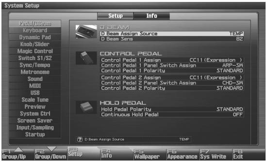
text_image
System Setup Setup Info D BEAM D Beam Assign Source TEMP D Beam Sens 82 CONTROL PEDAL Control Pedal 1 Assign CC11 (Expression ) Control Pedal 1 Panel Switch Assign ARP-SW Control Pedal 1 Polarity STANDARD Control Pedal 2 Assign CC11 (Expression ) Control Pedal 2 Panel Switch Assign CDO-SW Control Pedal 2 Polarity STANDARD HOLD PEDAL Hold Pedal Polarity STANDARD Continuous Hold Pedal OFF D Beam Assign Source TEMP F1 F2 F3 F4 F5 F6 F7 F8 Group/Up Group/Down Setup Info Wallpaper Appearance Sys Write ExitF-key operations in the System Setup screen
| F-key | Explanation | Page |
| F1Group/Up | Moves the edit group tab upward. | - |
| F2Group/Down | Moves the edit group tab downward. | - |
| F3Setup | Edits the system parameters. | p. 291 |
| F4Info | Displays system information. | p. 302 |
| F5Wallpaper | Specifies the wallpaper. | p. 303 |
| F6Appearance | Edits screen-related settings. | p. 304 |
| F7Sys Write | Saves system settings. | p. 290 |
| F8Exit | Returns to the previous screen. | - |
-
The parameters are organized into several edit groups. Use [F1 (Up)] [F2 (Down)] to switch tabs.
-
Use [CURSOR] to move the cursor to the parameter you wish to modify.
MEMO
When the cursor is located at a parameter value, you can press [ENTER] to access a window for setting the value.
-
When all the parameters cannot be shown within a single settings screen, a scroll bar will be displayed at the right side of the screen. In such cases, press ▼ to scroll the screen downward.
-
Turn the VALUE dial or press [INC] [DEC] to get the value you want.
-
Repeat steps 3–5 to set each System parameter you want to edit.
-
To save the settings you modified, press [F7 (Sys Write)] and perform the Write operation. If you do not want to save, press [EXIT] to return to the previous screen.
Saving the System Settings (System Write)
Changes you make to the System function settings are only temporary—they will be discarded as soon as the power is turned off. If you want to keep any changes you've made in the system settings, you must save them in internal system memory.
NOTE
When you perform the save procedure, the data that previously occupied the save destination will be lost. However, the factory setting data can be recovered by performing the Factory Reset procedure.
- Change the system function settings, and press [F7 (Sys Write)].
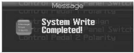
text_image
Message System Write Completed!The display will indicate "System Write Completed!" The data will be saved, and you're returned to the System Setup screen.
System Settings (Settings Common to All Modes)
Functions of System Parameters
This section explains what the different System parameters do, and also how these parameters are organized.
For details on these settings, refer to “How to Make System Function Settings” (p. 290).
Pedal/D Beam
NOTE
The usable range of the D Beam controller will become extremely small when used under strong direct sunlight. Please be aware of this when using the D Beam controller outside.
NOTE
The sensitivity of the D Beam controller will change depending on the amount of light in the vicinity of the unit. If it does not function as you expect, adjust the sensitivity as appropriate for the brightness of your location. Increase this value will raise the sensitivity (p. 291).
D Beam Assign Source
This specifies whether the D Beam Controller switch will follow the system settings (SYS) or follow the live set or studio set (TEMP).
Value: SYS, TEMP
D Beam Sens (D Beam Sensitivity)
This sets the D Beam controller's sensitivity. Increasing this value will raise the sensitivity.
Value: 0–127
Control Pedal 1 Assign Control Pedal 2 Assign
This specifies the function of each pedal connected to the FOOT PEDAL CTRL 1, 2 jacks.
Value
OFF: Off
CC01-31, 32(OFF), 33-95:
Controller numbers 1–31, 32(OFF), 33–95
AFTERTOUCH: Aftertouch
BEND UP: The pitch will rise in semitone steps (maximum 4 octaves) each time you press the pedal.
BEND DOWN: The pitch will fall in semitone steps (maximum 4 octaves) each time you press the pedal.
START/STOP: The sequencer will start/stop.
TAP TEMPO: Tap tempo (a tempo specified by the interval at which you press the pedal).
PROG UP: The next sound number will be selected.
PROG DOWN: The previous sound number will be selected.
USER GROUP UP: The user group patch of the next number or bank will be selected.
USER GROUP DOWN: The user group patch of the previous number or bank will be selected.
FAVORITE UP: The favorite patch/live set/studio set of the next number or bank will be selected.
FAVORITE DOWN: The favorite patch/live set/studio set of the previous number or bank will be selected.
PANEL SWITCH: The result will be the same as pressing the switch assigned by Panel Switch Assign (see below).
Control Pedal 1 Panel Switch Assign Control Pedal 2 Panel Switch Assign
Specifies the switch that will operate when Pedal 1 Assign or Pedal 2 Assign (see preceding item) are set to "PANEL SWITCH."
Control Pedal 1 Polarity Control Pedal 2 Polarity
Selects the polarity of the pedal. On some pedals, the electrical signal output by the pedal when it is pressed or released is the opposite of other pedals. If your pedal has an effect opposite of what you expect, set this parameter to "REVERSE." If you are using a Roland pedal (that has no polarity switch), set this parameter to "STANDARD."
Value: STANDARD, REVERSE
Hold Pedal Polarity
Select the polarity of the Hold pedal. On some pedals, the electrical signal output by the pedal when it is pressed or released is the opposite of other pedals. If your pedal has an effect opposite of what you expect, set this parameter to “REVERSE.” If you are using a Roland pedal (that has no polarity switch), set this parameter to “STANDARD.”
Range: STANDARD, REVERSE
Continuous Hold Pedal
This setting determines whether the HOLD PEDAL jack will provide support for half-pedaling (ON), or not (OFF). When this is set to support use of half-pedaling techniques, you can then connect an optional expression pedal (DP-8, etc.), and employ pedal work to achieve even finer control in performances in which piano tones are used.
Value: OFF, ON
Keyboard
Keyboard Velocity
Specifies the velocity value that will be transmitted when you play the keyboard. If you want actual keyboard velocity to be transmitted, set this to "REAL." If you want a fixed velocity value to be transmitted regardless of how you play, specify the desired value (1–127).
Value: REAL, 1–127
Keyboard Velocity Curve
Adjusts the keyboard's touch.
Value
LIGHT: Light weight synthesizer keyboard like
MEDIUM: Standard
HEAVY: Acoustic piano simulation
Keyboard Velocity Sens (Keyboard Velocity Sensitivity)
Adjusts the sensitivity of the keyboard. As you increase this setting, higher velocity values will be transmitted according to the force with which you play. Normally you will leave this set at "0."
Value: -63- +63
Aftertouch Sens (Aftertouch Sensitivity)
Specifies the Aftertouch sensitivity. Higher values will allow Aftertouch to be applied more easily. Normally you will leave this at "100."
Value: 0–100
Dynamic Pad
Pad Assign Source
Specifies whether changes in pad mode will follow the system's Pad Mode setting (SYS) or follow the live set or studio set (TEMP).
Value: SYS, TEMP
Pad Velocity
For all sixteen pads, this specifies the velocity (loudness) that is produced when you strike a pad. With the “REAL” setting, you’ll be able to produce dynamics by varying your striking force. With a setting of “1–127,” the pads will produce the specified velocity value regardless of your actual striking force.
Value: REAL, 1-127
Pad Sens (Pad Sensitivity)
Specifies the relation between your striking force and the velocity that is produced.
Value
LIGHT: It will be easy to produce the maximum velocity without having to strike very hard.
MEDIUM: This is the standard pad sensitivity setting.
HEAVY: You will have to strike quite strongly to produce the maximum velocity.
Pad Aftertouch Sens (Pad Aftertouch Sensitivity)
"Aftertouch" means additional pressure that you apply on a pad after striking it. This setting adjusts the aftertouch sensitivity. Higher values make it easier to apply aftertouch. Normally you will leave this at a setting of "100."
Value: 0-100
Pad Roll Resolution
Specifies the speed of repeated strikes when using the pads to play rolls.
Values: ♩, ♩₃, ♩, ♩₃, ♩, ♩₃, ♩, ♩₃
Pad Mode
Specifies the pad mode (p. 188) when the Fantom-G starts up (when a project is loaded).
Value: SAMPLE PAD, RHYTHM, CHORD MEMORY, ARPEGGIO, RPS, RHYTHM PTN, TONE SEL/SW, TRACK MUTE, BOOKMARK, MIDI TX SW, EFFECT SW, PATCH MFX SW, PART SELECT, PART MUTE, USER GROUP, FAVORITE
RPS Set Assign Source
You can specify whether the RPS Set Number will follow the setting of each Live / Studio Set (TEMP) or the setting for the entire Fantom-G (SYS).
Value
TEMP: Use the RPS Set Number of each Live / Studio Set
SYS: Use the Fantom-G's global settings
Rhythm Pattern Set Assign Source
You can specify whether the Rhythm Pattern Set Number will follow the setting of each Live / Studio Set (TEMP) or the setting for the entire Fantom-G (SYS).
Value
TEMP: Use the Rhythm Pattern Set Number of each Live / Studio Set
SYS: Use the Fantom-G's global settings
System Settings (Settings Common to All Modes)
Knob/Slider
Knob Slider Mode
Specifies whether, when a knob or slider is moved, its position will immediately be output as control data (DIRECT) or whether control data will be output only after the knob or slider position has passed through the value of the parameter (CATCH).
If you select "MULTI" as the Knob Slider Mode setting, you'll be able to use the knobs, sliders, D Beam, and S1/S2 buttons to simultaneously control multiple parts (each part whose keyboard switch is on).
Value
DIRECT: Moving a knob or slider will always transmit the control data of its current position
CATCH: When you move a knob or slider, it will begin transmitting control data only when its position passes the value of the parameter
MULTI: The knobs, sliders, D Beam, and S1/S2 buttons will simultaneously control multiple parts (each part whose keyboard switch is on). The knobs and sliders will operate in the same way as "DIRECT."
MEMO
MULTI (multi-part control) will control multiple parts only if CC, AFTERTOUCH, or PITCH BEND is assigned to the controller.
NOTE
Depending on the parameter being controlled with the sliders or controls, you may not be able to obtain the CATCH effect, even though you've set the Knob Slider Mode to "CATCH."
Knob Assign Select
Specifies whether the operation of knobs 1–4 will automatically change according to the screen (SCREEN) or will be fixed at the Knob 1–4 Assign settings (FIX).
Value: FIX, SCREEN
Knob Assign Source
Specifies whether the operation of knobs 1–4 will follow the system settings Knob 1–4 Assign (SYS) or the setting of the live set or studio set (TEMP).
Value: SYS, TEMP
Knob 1-4 Assign
Specify the functions that will be controlled by the knobs.
Value
OFF: Off
CC01-31, CC32(OFF), 33-95:
Control Change
AFTERTOUCH: Aftertouch
PITCH BEND: Pitch Bend
ARPEGGIO ACCENT: Arpeggio accent rate
ARPEGGIO SHUFFLE: Arpeggio shuffle rate
ARPEGGIO OCT UP: The range in which the arpeggio is sounded will rise in steps of an octave.
ARPEGGIO OCT DOWN: The range in which the arpeggio is sounded will lower in steps of an octave.
MASTER LEVEL: Master Level (p. 297)
DIGITAL/USB INPUT LEVEL:
Digital/USB Input Level (p. 258)
* If the system setting “Knob Assign Source” (p. 293) is “System,” the system setting will be used. If this is “TEMP,” the setting of the live set or studio set will be used.
Slider Assign Select
Specifies whether the operation of sliders 1–8 will automatically change according to the screen (SCREEN) or will be fixed at the Slider 1–8 Assign settings (FIX).
Value: FIX, SCREEN
Slider Assign Source
Specifies whether the operation of sliders 1–8 will follow the system settings Slider 1–8 Assign (SYS) or the settings of the live set or studio set (TEMP).
Value: SYS, TEMP
Slider 1-8 Assign
Specify the functions that will be controlled by the sliders.
Value
OFF: Off
CC01-31, CC32(OFF), 33-95:
Control Change
AFTERTOUCH: Aftertouch
PITCH BEND: Pitch Bend
ARPEGGIO ACCENT: Arpeggio accent rate
ARPEGGIO SHUFFLE: Arpeggio shuffle rate
ARPEGGIO OCT UP: The range in which the arpeggio is sounded will rise in steps of an octave.
ARPEGGIO OCT DOWN: The range in which the arpeggio is sounded will lower in steps of an octave.
* If the system setting “Slider Assign Source”(p. 293) is “System,” the system setting will be used. If this is “TEMP,” the setting of the live set or studio set will be used.
Magic Control
Magic Control is a function that automatically switches the role of knob 4 and slider 8 according to the screen. In the Patch List screen (p. 49), knob 4 will select the category, and slider 8 will scroll the list.
Knob 4 Assign
Specify the functions that will be controlled by the knob 4.
Value
OFF: Off
CATEGORY/BANK: Switch the category/bank
SCROLL COARSE: Scroll the list
SCROLL FINE: Scroll the list finely
Slider 8 Assign
Specify the functions that will be controlled by the slider 8.
Value
OFF: Off
CATEGORY/BANK: Switch the category/bank
SCROLL COARSE: Scroll the list
SCROLL FINE: Scroll the list finely
Switch S1/S2
Switch S1/S2 Assign Source
Specifies whether the S1/S2 switches will follow the system settings (SYS) or the settings of the live set or studio set (TEMP).
Value: SYS, TEMP
Switch S1/S2 Assign
Specify the functions that will be controlled by the [S1] [S2] switches.
Value
Live Set: OFF, CC01 - CC31, CC32 (OFF), CC33 - CC95, AFTERTOUCH, MONO/POLY, PFX SWITCH, MFX SWITCH, RESERVE, CHORUS SWITCH, REVERB SWITCH, MASTERING SWITCH, MASTER KEY UP, MASTER KEY DOWN, SCALE TUNE SWITCH
Studio Set: OFF, CC01 - CC31, CC32 (OFF), CC33 - CC95, AFTERTOUCH, MONO/POLY, PFX SWITCH, MFX1 SWITCH, MFX2 SWITCH, CHORUS SWITCH, REVERB SWITCH, MASTERING SWITCH, MASTER KEY UP, MASTER KEY DOWN, SCALE TUNE SWITCH
Switch S1/S2 Assign Mode
Turns the [S1] [S2] switches function LATCH/MOMENTARY.
Value
LATCH: The on/off status will alternate each time you press [S1] [S2].
MOMENTARY: The status will be on only while you hold down [S1] [S2].
System Settings (Settings Common to All Modes)
Sync/Temp
Sync Mode
Specify the synchronization message that the Fantom-G's sequencer will use for operation.
Value
MASTER: The Fantom-G will be the master. Choose this setting when using the Fantom-G by itself without synchronizing to another device, or when you want other MIDI devices to synchronize to the Fantom-G.
SLAVE-MIDI: The Fantom-G will be the slave. Choose this setting when you want the Fantom-G to synchronize to MIDI Clock messages received from another MIDI device.
SLAVE-MTC: The Fantom-G will be the slave. Choose this setting when you want the Fantom-G to synchronize to MTC (MIDI Time Code) received from an external device.
REMOTE: Use this setting when you wish an external MIDI device to have remote start/pause/stop control. The tempo will be in accord with what has been set on the Fantom-G.
MIDI Clock and MTC
MIDI Clock and MTC (MIDI Time Code) are both messages used for synchronization. Select either of them depending on the application.
MIDI Clock transmits and synchronizes operations to a sequencer's performance tempo, whereas MTC synchronizes operations between devices based on an absolute time.
Sync Output (Sync Output Switch)
Set this parameter ON when you want synchronization related MIDI messages (MIDI Clock, Start, Continue, Stop, Song Position Pointer and Song Select) to be transmitted to an external MIDI device. If not, set it OFF.
Value: OFF, ON
Clock Source
When the Sync Mode is set to SLAVE-MIDI or SLAVE-MTC, this setting specifies whether the Fantom-G will synchronize to the tempo from the MIDI IN connector or the tempo from the USB connector.
Value
MIDI: Synchronize to the tempo from the MIDI IN connector.
USB: Synchronize to the tempo from the USB connector.
MMC Mode
When synchronizing the Fantom-G with a hard disk recorder, such as one from the Roland VS series, specify which synchronization signal the Fantom-G's sequencer will use for operation.
Value
MASTER: The Fantom-G will be the master. Use this setting when you want other devices to follow the operation of the Fantom-G.
SLAVE: The Fantom-G will be the slave. Use this setting when you want the Fantom-G to receive MMC (MIDI Machine Control) from an external device and operate accordingly.
MEMO
MMC (MIDI Machine Control) is a specification that allows MIDI messages to be used to control devices such as tape recorders, VTR's, and digital recording systems. Thirty-seven MMC commands are available, including Stop and Play.
MMC Output (MMC Output Switch)
Turn this “ON” if you want to synchronize with a hard disk recorder, such as one from the Roland VS series. When set “ON,” MMC (MIDI Machine Control) related commands (Play, Stop and Locate) will be transmitted.
Value: OFF, ON
MTC Sync Output (MTC Sync Output Switch)
Set this parameter ON when you want MTC (MIDI Time Code) to be transmitted to an external MIDI device. If not, set it OFF.
Value: OFF, ON
MTC Frame Rate
Specify the MTC frame rate. Make sure that the same mode is set in both master and slave devices.
Value
24: 24 frames per second
25: 25 frames per second
29N: 29 frames per second
29D: 29 frames per second
30: 30 frames per second
TIP
When synchronizing with a hard disk recorder such as the Roland VS series, any frame rate is all right—as long as the setting matches that of the Fantom-G. However, when synchronizing operation with video devices such as video decks, the video device's frame rate is fixed, so the Fantom-G's setting must correspond to that frame rate.
Types of MTC
The types of MTC that can be selected by the Fantom-G are shown below. Select the same frame rate as that set for the external device. When not using a video device, then any frame rate may be selected as long as the rates are the same on both devices being synchronized.
30: This is 30 frames per second, non-drop format. This is used by audio devices such as analog tape recorders, and for NTSC format black and white video (used in Japan and the U.S.).
29N: This is 29.97 frames per second, non-drop format. This is used for NTSC format color video (used in Japan and the U.S.).
29D: 29.97 frames per second drop format. This is used for NTSC format color video (used in Japan and the U.S.).
25: 25 frame per second frame rate. This is used for SECAM or PAL format video, audio equipment, and film (used in Europe and elsewhere).
24: 24 frame per second frame rate. This is used for video, audio devices, and film in the US.
Non-Drop Format and Drop Format
There are two types of format used by NTSC video cassette recorders, non-drop and drop. Non-drop format features continuous time code, whereas in drop format, which is used for NTSC color video format, the first two frames of every minute are dropped, except for those at ten-minute intervals. In most video and audio production, since formats with continuous frames are easier to deal with, non-drop is generally used. In contrast, in situations such as in broadcast, where the time code must match actual clock time, drop format is used.
MTC Offset Time Hour
Coordinates the playback timing of the Fantom-G and the external device in an hour units.
Value: 00–23 hours
MTC Offset Time Minute
Coordinates the playback timing of the Fantom-G and the external device in a minute units.
Value: 00–59 minutes
MTC Offset Time Second
Coordinates the playback timing of the Fantom-G and the external device in a second units.
Value: 00–59 seconds
MTC Offset Time Frame
Coordinates the playback timing of the Fantom-G and the external device in a frame units.
Value: 00–29 frames
(The maximum value will depend on the frame rate setting.)
MTC Error Level
Determines how often the reception status is checked when MTC is being received from an external device. Stop synchronization if a problem becomes apparent with the check.
Value: 0–10 (the checking interval will be longer for larger values)
MEMO
In strict terms, the lower the numerical value set, the more accurate the check is. However, playback may be stopped overly frequently if too rigorous a check is made, and this soon becomes inconvenient. By raising the Error Level setting, then even if problems with the reception of MTC do occur, synchronization can then continue as long as such problems remain at a level that does not cause undue problems.
Tempo Assign Source
You can specify whether the tempo will follow the setting of each Live / Studio Set (TEMP) or the tempo setting of the song (SYS).
Value
TEMP: Use the tempo of each Live / Studio Set
SYS: Switching the Live / Studio Set will not change the tempo (the song's tempo will be used)
Metronome
Metronome Mode
Specifies when you want the metronome to sound.
* If [F7 (Click)] in the Tempo window which appears when you press [TEMPO] is lit in red, the metronome will always sound.
Value
OFF: Will not sound.
PLAY-ONLY: Will sound only during playback.
REC-ONLY: Metronome will sound only for recording.
PLAY&REC: Metronome will sound for playback and recording.
ALWAYS: Metronome will always sound.
Metronome Level
You can adjust the volume of the metronome.
Value: 0–10
Metronome Sound
Selects the metronome sound.
Value
TYPE 1: A conventional metronome sound will be heard. A bell will sound on the first beat.
TYPE 2: Clicks will sound.
TYPE 3: Beeps will sound.
TYPE 4: Cowbell will sound.
Beat Indicator Mode
You can specify how the [PLAY] button (beat indicator) on the panel will blink.
Value
ALWAYS: Always blinks at the specified tempo.
PLAY&REC: Blinks only during playback and recording.
Sound
Local Switch
The Local Switch determines whether the internal sound generator is disconnected (OFF) from the controller section (keyboard, pad, pitch bend/modulation lever, knobs, buttons, D Beam controller, pedal, and so on); or not disconnected (ON). Normally this is left "ON," but if you wish to use the Fantom-G's keyboard and controllers to control only external sound modules, set it to "OFF."
Value: OFF, ON
Using the Local Switch
If you're using external sequencer software in conjunction with the Fantom-G's keyboard/controllers and sound generator, you should turn the Local switch OFF for the reasons explained below.
Connecting the Fantom-G to an external sequencer
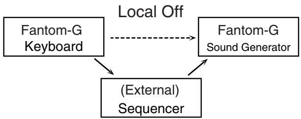
flowchart
graph TD
    A["Fantom-G Keyboard"] -->|Local Off| B["Fantom-G Sound Generator"]
    A --> C["(External) Sequencer"]
    B --> C
Typically, things are hooked up so the data travels as follows: the Fantom-G's keyboard → your external sequencer software → the Fantom-G's sound generator. Normally, the Fantom-G's keyboard section is internally connected to its sound generator section; this internal connection is controlled by the Local Switch. If you turn the Local Switch off, the Fantom-G's keyboard and sound generator sections will be independent, allowing you to use the connection described above with your external sequencer software.
Master Tune
Adjusts the overall tuning of the Fantom-G. The display shows the frequency of the A4 note (center A).
Value: 415.3–466.2 Hz
Master Level
Adjusts the volume of the entire Fantom-G.
Value: 0–127
Master Reverb Level
Adjusts the reverb level of the entire Fantom-G.
Value: 0–127
How Do I Adjust the Volume?
MASTER LEVEL adjusts the volume of both the OUTPUT A jacks and the DIGITAL AUDIO OUT jack. The front panel VOLUME knob adjusts only the volume of the OUTPUT A jacks. Here's an explanation of what you need to adjust depending on the output jacks you're using.
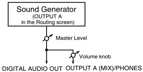
flowchart
graph TD
    A["Sound Generator (OUTPUT A in the Routing screen)"] --> B["Master Level"]
    B --> C["Digital Audio OUT OUTPUT A (MIX)/PHONES"]
    B --> D["Volume knob"]
When using the OUTPUT A jacks: adjust using the VOLUME knob
The front panel VOLUME knob controls the volume of the OUTPUT A jacks. This means that if you're outputting from the OUTPUT A jacks, the simplest way is to leave the Master Level fixed at 127 (the default setting), and use the VOLUME knob to control the volume.
When using the DIGITAL AUDIO OUT jack: adjust using Master Level
Master Level controls both the OUTPUT A jacks and the DIGITAL AUDIO OUT jack. This means that if you're outputting from DIGITAL OUT, use Master Level to adjust the volume.
NOTE
The Master Level setting is temporary, and will be lost when you turn off the power. If you want to keep the Master Level setting you edited, save the master level in the internal system memory. → “Saving the System
Settings (System Write)" (p. 290)
Output Gain
This adjusts the output gain from the Fantom-G's Analog Out and Digital Out. When, for example, there are relatively few voices being sounded, boosting the output gain can let you attain the most suitable output level for recording and other purposes.
Value: -12- +12
Mix/Parallel
Specifies how the sound of the entire Fantom-G will be output.
Value
MIX: Set this to have the collective output of all sounds output from the OUTPUT A (MIX) jacks. When you want to check the final overall sound being output, set to MIX.
MEMO
Sounds which are set in the respective Output Assign to be output from the INDIVIDUAL 3 jack are output from the left OUTPUT A (MIX) jack; sounds which are set to be output from the INDIVIDUAL 4 jack are output from the right OUTPUT A (MIX) jack.
TIP
Sounds output from the PHONES jack are the same as those output from the OUTPUT A (MIX) jacks. Therefore, any sounds set with Output Assign to be output from the OUTPUT B jacks is not output from the PHONES jack. Be sure to have any sound you want to hear through the headphones set to "MIX."
PARALLEL: Output according to each Output Assign settings.
Master Key Shift
Shifts the overall pitch of the Fantom-G in semitone steps.
Value: -24- +24
Patch Remain (Patch Remain Switch)
Specifies whether currently sounding notes will continue sounding when another patch or rhythm set is selected (ON), or not (OFF).
Value: OFF, ON
* When in Studio mode: Depending on the effect settings, currently sounding notes may not remain in some cases.
* When in Single mode or Live mode: The Patch Remain function is valid only for the most recently selected sound. Notes of a sound selected earlier may be interrupted.
* The Patch Remain setting does not apply to sounds of an expansion board.
Control Remain (Control Remain Switch)
Specifies whether changes in the sound and volume produced by received MIDI data such as volume and pan (CC 5, 7, 10, 65, 68, 71–74, RPN 0, 1, 2, MONO ON, POLY ON) and by the various controllers will be maintained (ON) or not maintained (OFF) when you select another patch or rhythm set.
Value: OFF, ON
System Settings (Settings Common to All Modes)
MIDI
Device ID (Device ID Number)
When you want to transmit or receive System Exclusive messages, set this parameter to match the Device ID number of the other MIDI device.
Value: 17–32
Studio Set Control Channel
Studio Set Control Channel selects the MIDI receive channel used during switching of studio sets when MIDI messages (Program Change/Bank Select) are sent from an external MIDI device. Set this to “OFF” if studio sets are not to be switched from an external MIDI device.
Value: 1–16, OFF
NOTE
If only a program change is received, and if the Studio Set Control Channel parameter setting coincides with the MIDI receive channel of a part, priority will be given to switching the studio set.
Live Set Control Channel
Live Set Control Channel selects the MIDI receive channel used during switching of live sets when MIDI messages (Program Change/Bank Select) are sent from an external MIDI device. Set this to “OFF” if live sets are not to be switched from an external MIDI device.
Value: 1–16, OFF
NOTE
If only a program change is received, and if the Live Set Control Channel parameter setting coincides with the MIDI receive channel of a part, priority will be given to switching the live set.
Transmit Program Change (Transmit Program Change Switch)
Specifies whether Program Change messages will be transmitted (ON) or not (OFF).
Value: OFF, ON
Transmit Bank Select (Transmit Bank Select Switch)
Specifies whether Bank Select messages will be transmitted (ON) or not (OFF).
Value: OFF, ON
Transmit Active Sensing (Transmit Active Sensing Switch)
Specifies whether Active Sensing messages will be transmitted (ON) or not (OFF).
Value: OFF, ON
Transmit Edit Data (Transmit Edit Data Switch)
Specify whether changes you make in the settings of a patch, live set or studio set will be transmitted as system exclusive messages (ON), or will not be transmitted (OFF).
Value: OFF, ON
Soft Through (Soft Through Switch)
Thru function re-transmits all messages received at the MIDI IN connector to the MIDI OUT connector without modifying them in any way.
Value: OFF, ON
Remote Keyboard Sw (Remote Keyboard Switch)
Set this parameter "ON" when you want to use an external MIDI keyboard instead of the Fantom-G's keyboard. In this case, the MIDI transmit channel of the external MIDI keyboard can be set to any channel. Normally you will leave this parameter "OFF."
Value: OFF, ON
TIP
Turn this “ON” when you want to control the Fantom-G from an external MIDI device when performing with the Arpeggio or Chord Memory function.
Receive Program Change (Receive Program Change Switch)
Specifies whether Program Change messages will be received (ON) or not (OFF).
Value: OFF, ON
Receive Bank Select (Receive Bank Select Switch)
Specifies whether Bank Select messages will be received (ON) or not (OFF).
Value: OFF, ON
Receive Exclusive (Receive System Exclusive Switch)
Specifies whether System Exclusive messages will be received (ON) or not (OFF).
Value: OFF, ON
Receive GM1 System On (Receive GM System On Switch)
Specifies whether General MIDI System On messages will be received (ON) or not (OFF).
Value: OFF, ON
Receive GM2 System On (Receive GM2 System On Switch)
Specifies whether General MIDI 2 System On messages will be received (ON) or not (OFF).
Value: OFF, ON
Receive GS Reset (Receive GS Reset Switch)
Specifies whether GS Reset messages will be received (ON) or not (OFF).
Value: OFF, ON
System Settings (Settings Common to All Modes)
USB
USB-MIDI Thru Sw (USB-MIDI Thru Switch)
This switch specifies whether MIDI messages received at the USB connector/MIDI connector will be retransmitted from the USB connector/MIDI OUT connector (ON) or not (OFF).
Value: OFF, ON
Scale Tune
Scale Tune Switch
Turn this on when you wish to use a tuning scale other than equal temperament.
Value: OFF, ON
The Fantom-G allows you to play the keyboard using temperaments other than equal temperament. The pitch is specified in one-cent units relative to the equal tempered pitch.
MEMO
One-cent is 1/100th of a semitone.
- The selected scale applies to MIDI messages received from an external MIDI device.
Patch Scale Tune for C-B
Make scale tune settings for Single mode.
Value: -64- +63
MEMO
One set of Scale Tune settings can be created in Single mode. In Live / Studio mode, this can be set for each part of the Live / Studio set (p. 138).
In Single mode, this is valid only for the keyboard part.
Equal Temperament
This tuning divides the octave into 12 equal parts, and is the most widely used method of temperament used in Western music. The Fantom-G employs equal temperament when the Scale Tune Switch is set to “OFF.”
Just Temperament (Tonic of C)
Compared with equal temperament, the principle triads sound pure in this tuning. However, this effect is achieved only in one key, and the triads will become ambiguous if you transpose.
Arabian Scale
In this scale, E and B are a quarter note lower and C#, F# and G# are a quarter-note higher compared to equal temperament. The intervals between G and B, C and E, F and G#, Bb and C#, and Eb and F# have a natural third—the interval between a major third and a minor third. On the Fantom-G, you can use Arabian temperament in the three keys of G, C and F.
| Note name | Equal temperament | Just Temperament (tonic C) | Arabian Scale |
| C | 0 | 0 | -6 |
| C# | 0 | -8 | +45 |
| D | 0 | +4 | -2 |
| Eb | 0 | +16 | -12 |
| E | 0 | -14 | -51 |
| F | 0 | -2 | -8 |
| F# | 0 | -10 | +43 |
| G | 0 | +2 | -4 |
| G# | 0 | +14 | +47 |
| A | 0 | -16 | 0 |
| Bb | 0 | +14 | -10 |
| B | 0 | -12 | -49 |
Preview
Preview Mode
SINGLE: The notes specified by Note Number 1–4 parameter will sound successively one by one.
CHORD: The notes specified by Note Number 1–4 parameter will sound simultaneously.
PHRASE: The Phrase associated with the patch's type/ category is played.
Preview 1-4 Note Number
Specify the pitch of the four notes that will sound when the Preview Mode parameter is set to "SINGLE" or "CHORD."
Value: C-1-G9
NOTE
If "PHRASE" is selected for the Preview Mode parameter, these settings will have no effect.
Preview 1-4 Velocity
Specify the velocity of the four notes that will sound when the Preview Mode parameter is set to "SINGLE" or "CHORD."
Value: OFF, 0–127
NOTE
If "PHRASE" is selected for the Preview Mode parameter, these settings will have no effect.
System Ctrl
System Control 1-4 Source
System Control Assign selects the MIDI message used as the System Control.
System Control
This function, which departs from previously used methods, and instead allows you to use MIDI messages to change tone settings in realtime, is called the Matrix Control (p. 109). Similarly, the function allowing you to use MIDI messages to change multi-effects settings in realtime is called the Multi-effects Control (p. 158).
Normally, the Matrix Control is used for making patch settings, and the Multi-effects Control for making settings to patches, rhythm sets, sample sets, live sets and studio sets. However, if you do not need to change the MIDI messages used for matrix control or multi-effects control by each patch/rhythm set/sample set/live set/studio set, or if you want to use a specific MIDI message for matrix control or multi-effects control, you will want to make use of System Control. In other words, you could call the System Controls global Matrix Control/Multi-effects Control for the entire Fantom-G.
You can use up to four System Controls.
Value
OFF: The system control will not be used.
CC01-31, CC32(OFF), 33-95:
Control Change
PITCH BEND: Pitch Bend
AFTERTOUCH: Aftertouch
Screen Saver
Screen Saver Type
Select the type of screen saver.
Value: 1–16
Screen Saver Time
Set the time (minutes) until the screen saver begins working. If this is OFF, the screen saver will not appear.
Value: OFF, 1–60 min.
Input/Sampling
Input Select
Input source of the external input sound
Value
DIGITAL IN: DIGITAL AUDIO IN jack
LINE IN L/R: INPUT jacks L/R (stereo)
LINE IN L: INPUT jack L (mono)
MIC/GUITAR: MIC/GUITAR jack
USB AUDIO: USB connector
* When an external device is connected to the DIGITAL AUDIO IN connector and you disconnect the cable or power-off the external device, noise may subsequently be heard in the input from DIGITAL AUDIO IN. If this occurs, correctly reconnect the external device, or turn the Fantom-G's [MIX IN] switch off.
Digital/USB Input Level
If you've set Input Select to DIGITAL IN or USB AUDIO, this adjusts the input level.
Value: 0–127
Mix In Switch
Turns the external input on/off.
Value: OFF, ON
Default File Type
Specifies the file format used when saving a sample.
Value: WAV, AIFF
Pre Sample Time
The length of sound preceding the moment at which sampling was manually or automatically initiated that will be captured in the sample. This lets you prevent the attack portion of the sound from being omitted from the sample.
Value: 0–1000 ms
System Settings (Settings Common to All Modes)
Trigger Level
Volume level at which sampling will begin when Auto Trig is ON. A setting of 0 is the minimum.
Value: 0–7
Gap Time
Length of silence at which the sample will be divided.
Whenever there is a silent region longer than the specified time, the sample will be divided at that point, and the next sample number will be assigned to the sound that follows. This parameter is valid only when you are using Auto Divide Sampling.
Value: 500, 1000, 1500, 2000 ms
Trimming Switch
If this is turned on, the Start point and End point settings will be automatically adjusted after sampling is performed, so any silent portions at the beginning or end of the sampled sound are excluded.
Value: OFF, ON
Skip Back Time
Specifies how much earlier in time that you want sampling to take place when you use Skip Back Sampling. If "OFF" selected, skip-back sampling cannot be performed.
Value: OFF, 5s–40s
Startup
Power Up Mode
This setting allows you to choose the mode that you want the Fantom-G to be in when load a project.
Value
SINGLE: The Fantom-G will be in Single mode when load a project.
STUDIO: The Fantom-G will be in Studio mode when load a project.
LIVE: The Fantom-G will be in Live mode when load a project.
Sequencer Auto Track Switch
In the Realtime Rec Standby window, when recording a song, this function will automatically select the same track number as the part you're recording. For example, if the current part of the sound generator is part 3, MIDI track 3 of the song will be selected. If the current part of the sound generator is part 10, MIDI track 10 of the song will be selected. This provides a more intuitive relationship between the parts of the sound generator and the tracks of the song.
"Auto Track Function" (p. 222)
Value
OFF: Auto Track function is off
ON: (default) Auto Track function is on
System Information (Info)
Here's how to view system information.
- Press [MENU] to access the menu.
- Turn the VALUE dial or use [CURSOR] to choose "System," and then press [ENTER].
- Press [F4 (Info)].
- Use [F1 (Up)] [F2 (Down)] to switch tabs.
Features
Displays the main features of the Fantom-G.
Memory Info (Memory Information)
Displays the amount of memory installed.
Expansion Info (Expansion board Information)
Displays the name of the expansion board that is installed.
Version Info (Version Information)
Displays the version of the Fantom-G.
Changing the Wallpaper (Wallpaper)
You can change the background image of the display.
Via USB memory (or internal memory), you can use your own photo or other image data as the background image.
- Press [MENU] to access the menu.
- Turn the VALUE dial or use [CURSOR] to choose "System," and then press [ENTER].
- Press [F5 (Wallpaper)].
The Wallpaper screen will appear. - Turn the VALUE dial to select the image that you want to use as the background, and press [F8 (OK)].
The selected image will be shown as the background.
MEMO
The changed wallpaper setting is temporary, and will be lost when you turn off the power. If you want to keep the setting, press [F7 (Sys Write)] to write it into the Fantom-G's system memory.
Importing an Image as Wallpaper (Import)
Via USB memory (or internal memory), you can use a bitmap file (Windows BMP format, 24-bit, 800x480 pixel) as wallpaper for the Fantom-G.
- On your computer, prepare the bitmap file (Windows BMP format, 24-bit, 800x480 pixel) that you want to use as wallpaper.
- Using the USB Storage function, copy the bitmap file to the "IMPORT" folder of USB memory or the Fantom-G's internal memory.
cf.
"Exchanging Files with Your Computer (USB Storage)" (p. 285)
-
Press [MENU] to access the menu.
-
Turn the VALUE dial to select "System," and then press [ENTER].
-
Press [F5 (Wallpaper)].
The Wallpaper screen will appear.
MEMO
Sixteen different images can be shown as the background. The imported file will overwrite the currently selected image. If you want to delete an imported file, select an image (1–16) and press [F2 (Delete)].
-
Press [F1 (Import BMP)].
-
Press [F1 (Internal)] or [F2 (USB Memory)] to select the import-source area (internal memory or USB memory).
-
Press ▲ or ▼ to select the file that you want to import.
-
Press [F8 (Select)].
The file you want to import will be displayed.
* To cancel, press [F7 (Cancel)].
- Press [F8 (Execute)].
The file will be imported.
* To cancel, press [F7 (Cancel)].
MEMO
The changed wallpaper setting is temporary, and will be lost when you turn off the power. If you want to keep the setting, press [F7 (Sys Write)] to write it into the Fantom-G's system memory.
Delete Wallpaper
Here's how to delete wallpaper that was imported by the user.
- Access the Wallpaper screen.
-
Turn the VALUE dial to select the image that you want to delete. Press [F2 (Delete)].
A confirmation window will appear. -
Press [F7 (OK)].
* If you decide to cancel, press [F8 (CANCEL)].
MEMO
You can't delete wallpaper that was provided as part of the factory settings.
Display-related Settings (Appearance)
Here you can make display-related settings. On the Fantom-G you can turn window transparency on/off, and specify the degree of transparency.
- Press [MENU] to access the menu.
- Turn the VALUE dial or use [CURSOR] to choose "System," and then press [ENTER].
- Press [F6 (Appearance)]. The Appearance screen will appear.
Transparent Switch
Specifies whether windows in the screen will be transparent (ON) or not (OFF).
Value: ON, OFF
Transparency
Specifies the degree of transparency for windows in the screen. Higher values produce greater transparency.
Value: 1–120%
What is V-LINK?
V-LINK ( V-LINK ) is a function that allows music and images to be performed together. By using MIDI to connect two or more V-LINK compatible devices, you can easily enjoy performing a wide range of visual effects that are linked to the expressive elements of a music performance.
For example, if you use the Fantom-G in conjunction with the motion dive .tokyo Performance Package, you'll be able to do the following.
- Use the Fantom-G's synthesizer to produce synchronized music and video performances.
- Play the Fantom-G's keyboard, pads or sequencer to switch images on the motion dive .tokyo Performance Package.
- Use the Fantom-G's 1–4 knobs and D Beam controller to control the brightness or hue of an image.
MEMO
In order to use V-LINK between the Fantom-G and the motion dive .tokyo Performance Package, you'll need to make connections using a MIDI cable (sold separately).
Connection Examples
As an example, we will use a setup in which the Fantom-G is connected to the motion dive .tokyo Performance Package. Use a MIDI cable to connect the Fantom-G's MIDI OUT connector to the MIDI IN connector of the Edirol MD-P1.
NOTE
To prevent malfunction or speaker damage, minimize the volume on all your equipment and turn off the power before you make connections.
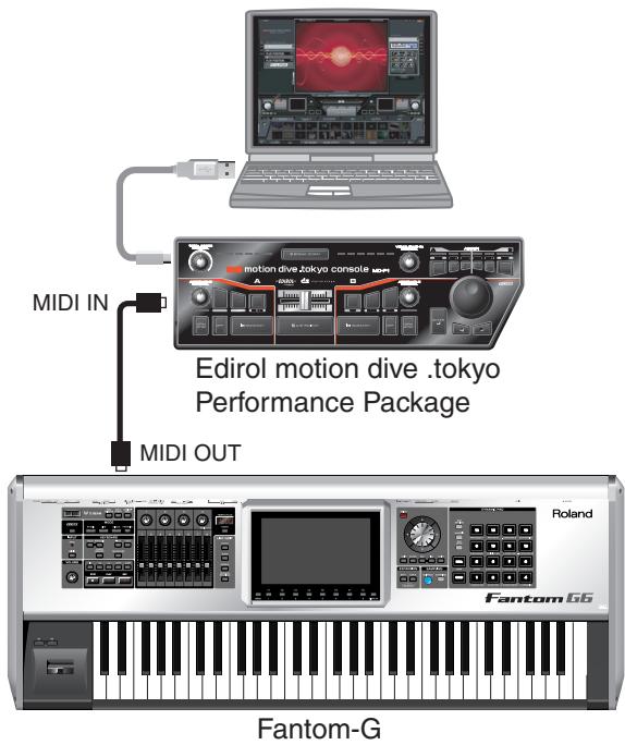
text_image
MIDI IN motion dive.tokyo console mpi A 500 40 30 20 10 B Edirol motion dive .tokyo Performance Package MIDI OUT Fantom-G Roland Fantom G6Turning the V-LINK ON/OFF
- In the left of the panel, press [V-LINK] so the indicator is lighted.
The V-LINK setting will be on.
In this state, you can operate the Fantom-G to manipulate images in sync with your performance.
MEMO
Each mode will function as usual even if V-LINK is on.
- Press [V-LINK] again.
The V-LINK button will go out, and the V-LINK setting will be off.
V-LINK Settings
- Press [V-LINK] to access the V-LINK SETUP screen.
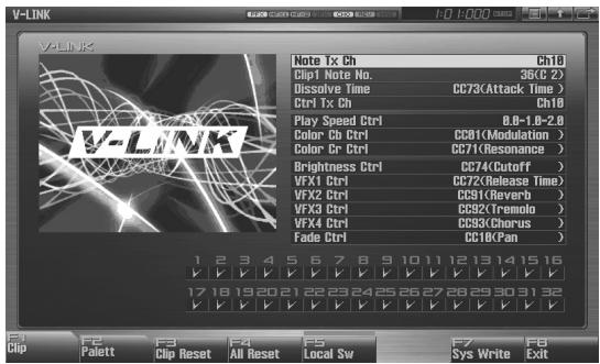
text_image
V-LINK Note Tx Ch Ch10 Clip1 Note No. 36(C 2) Dissolve Time CC73(Attack Time) Ctrl Tx Ch Ch10 Play Speed Ctrl 0.8-1.8-2.0 Color Cb Ctrl CC81(Modulation) Color Cr Ctrl CC71(Resonance) Brightness Ctrl CC74(Cutoff) VFX1 Ctrl CC72(Release Time) VFX2 Ctrl CC91(Reverb) VFX3 Ctrl CC92(Tremolo) VFX4 Ctrl CC93(Chorus) Fade Ctrl CC10(KPan) 1 2 3 4 5 6 7 8 9 10 11 12 13 14 15 16 ✓ ✓ ✓ ✓ ✓ ✓ ✓ ✓ ✓ ✓ ✓ ✓ ✓ ✓ ✓ 17 18 19 20 21 22 23 24 25 26 27 28 29 30 31 32 ✓ ✓ ✓ ✓ ✓ ✓ ✓ ✓ ✓ ✓ ✓ ✓ ✓ ✓ ✓ F1 F2 F3 F4 F5 F6 F7 F8 Clip Palett Clip Reset All ResetLocal Sw Sys Write Exit- Press [CURSOR] to move the cursor to a parameter, and turn the VALUE dial or use [INC] [DEC] to set the value.
* Specify the Pad Mode by pressing [F1 (Clip)] or [F2 (Palett)].
-
If you want to keep your settings, press [F7 (Sys Write)].
-
Press [EXIT].
You're returned to the previous screen.
V-LINK Parameters
Note Tx Ch
MIDI channel that will switch clips/palettes and will control dissolve time.
Value: 1–16
Clip 1 Note No.
Pads 1–16 correspond to clips (or palettes). We recommend that you press [PAD SETTING] to access the Pad setting screen, and set to "Note," using Quick Setup (p. 192) and set Clip1 Note No. to the same value as the "Pad Base Note" setting.
Value: 0(C-1)-127(G9)
Dissolve Time
Control change number that controls the dissolve time (time over which the image switches)
Value: OFF, CC1, CC5, CC7, CC10, CC11, CC71-74, CC91-93, Channel Aftertouch
Ctrl Tx Ch
MIDI channel that will control the color Cb/Cr, brightness, and video effect switching
Value: 1-16
Play Speed Ctrl
Range of video playback speed
The three values are the playback speeds (multiples of normal speed) at the left, center, and right positions of the pitch bend.
Value: 0.0-1.0-2.0, 0.5-1.0-2.0, 0.0-1.0-4.0, 0.5-1.0-4.0, 0.0-1.0-8.0, 0.5-1.0-8.0, 0.0-1.0-16.0, 0.5-1.0-16.0, 0.0-1.0-32.0, 0.5-1.0-32.0, 0.0-2.0-4.0, 0.0-4.0-8.0, 0.0-8.0-16.0, 0.0-16.0-32.0, -2.0-1.0-4.0, -6.0-1.0-8.0
Color Cb Ctrl
Control change number that controls the Cb color of the image
Color Cr Ctrl
Control change number that controls the Cr color of the image
Brightness Ctrl
Control change number that controls the brightness of the image
VFX1-4 Ctrl
Control change number that controls the video effect
Fade Ctrl
Control change number that controls the output fade
Value: OFF, CC1, CC5, CC7, CC10, CC11, CC71-74, CC91-93, Channel Aftertouch
PAD MODE
Selects whether the pads will switch clips or palettes.
Value: CLIP, PALETT
Press [F1 (Clip)]: switches clips
Press [F2 (Palett)]: switches palettes
Local Sw
Specifies whether the internal sound generator is disconnected (OFF) from the pads, or not (OFF).
Procedure: Press [F5 (Local Sw)].
Value: OFF, ON
Clip Filter
(check boxes 1-32)
Clips that are checked can be switched. Enable/disable switching for each clip
Value: OFF, ON
Using the Clip Filter
For example, suppose that of the rhythm set you input in the part used for V-LINK (i.e., the part of the same number as the Note Tx Channel), you want only the kick and snare to switch clips. In this case, check only the clips that correspond to the note numbers of the kick and snare. The clips will switch when the kick or snare plays.
Resetting the Image
Clip Reset
Turn off the image (solid black).
Procedure: Press [F3 (Clip Reset)].
All Reset
The effect applied to the image will be reset, and brightness, color difference, etc. will all return to the default value.
Procedure: Press [F4 (All Reset)].
09: Appendix
• Installing the Expansion Boar...... p. 308
- Expanding the DIMM Memory......p. 312
- Troubleshooting ...... p. 316
- Error Messages....p. 322
- About MIDI ...... p. 323
- Specifications ...... p. 326
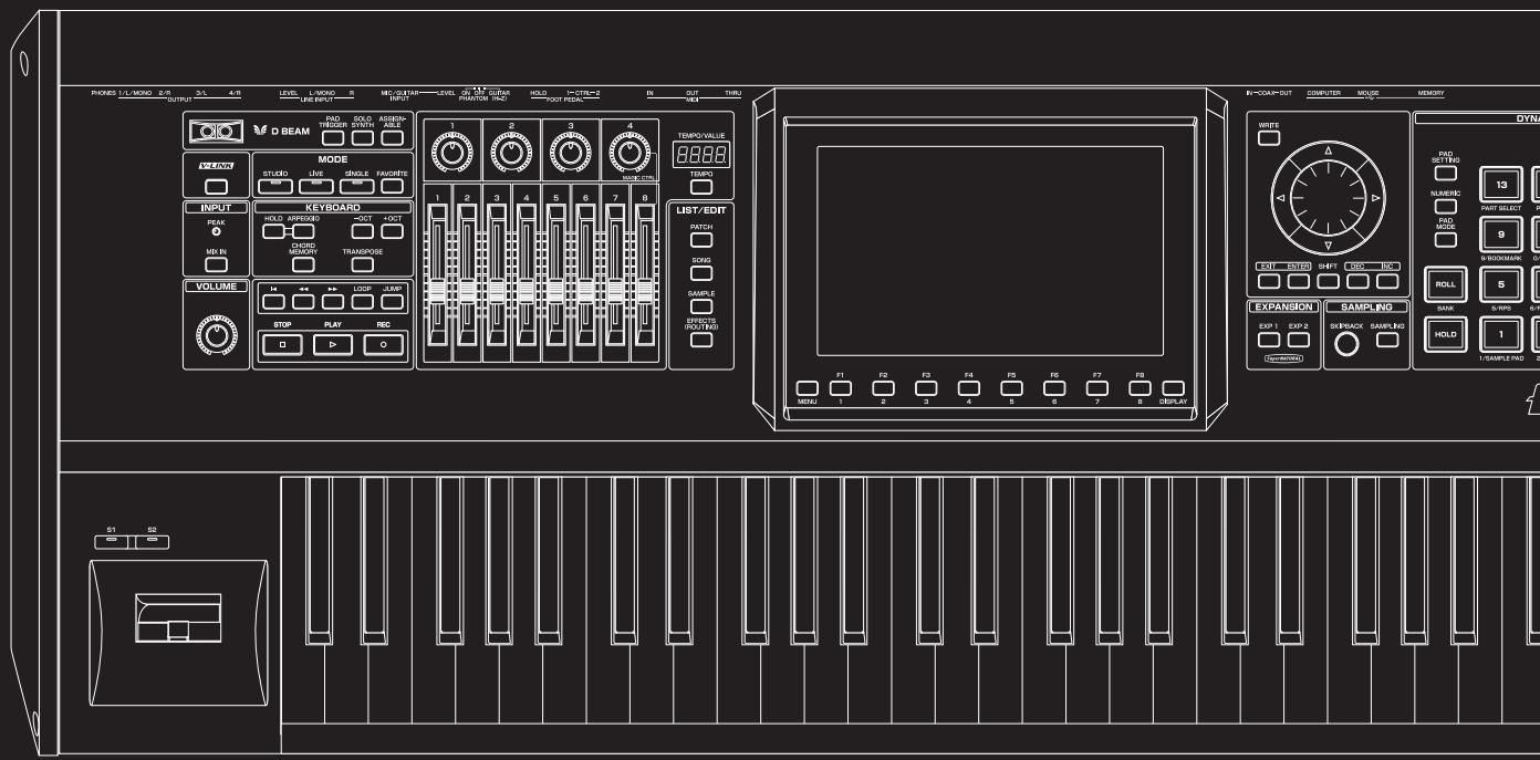
text_image
PROKES L/L MISO 2/R OUTPUT 3/L 4/R LEVEL L-MONO 5 MECUTAIN LEVEL 6 M.1.2 GRAV HOLD I-CTR=2 IN OUT TURI D BEAM RAD TRIGGER SWORD ASSEMB- MODE STUDIO LIVE SINGLE FAUCERS INPUT PEAK HOLD APPROXED 3OCT 4OCT CHORD GENDER TRANSPOSE VOLUME STOP PLAY REC LIST/EDIT MATCH DOYS SAMPLE CAPSIC (RDT/RDS) EXPANSION SAMPLING EXP 1 EXP 2 SREBACK SAMPLING HOLD 1 SAMPLE RAD 2 S1 SB MIN: 1 2 3 4 5 6 7 8 DISPLAYUp to two optional Expansion Boards (ARX series; sold separately) can be installed in the Fantom-G.
Cautions When Installing an Expansion Board
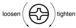
- To avoid the risk of damage to internal components that can be caused by static electricity, please carefully observe the following whenever you handle the board.
- Before you touch the board, always first grasp a metal object (such as a water pipe), so you are sure that any static electricity you might have been carrying has been discharged.
- When handling the board, grasp it only by its edges. Avoid touching any of the electronic components or connectors.
- Save the bag in which the board was originally shipped, and put the board back into it whenever you need to store or transport it.
- Use a Phillips screwdriver that is suitable for the size of the screw (a number 2 screwdriver). If an unsuitable screwdriver is used, the head of the screw may be stripped.
- To remove a screw, rotate the screwdriver counter-clockwise. To tighten the screws, rotate the screwdriver clockwise.
- When installing Expansion Boards, remove only the specified screws.
- Be careful that the screws you remove do not drop into the interior of the Fantom-G.
- Do not leave the bottom cover removed. After installation of the Expansion Boards is complete, be sure to replace the cover.
- Be careful not to cut your hand on the opening for installing the board.
- Do not touch any of the printed circuit pathways or connection terminals.
- Never use excessive force when installing a circuit board. If it doesn't fit properly on the first attempt, remove the board and try again.
- When circuit board installation is complete, double-check your work.
- Always turn the unit off and unplug the power cord before attempting installation of the circuit board (ARX series).
- Install only the specified circuit board(s) (ARX series). Remove only the specified screws.
- When turning the unit upside-down, get a bunch of newspapers or magazines, and place them under the four corners or at both ends to prevent damage to the buttons and controls. Also, you should try to orient the unit so no buttons or controls get damaged.
- When turning the Fantom-G8 upside-down, at least two persons are required to safely lift and turn the Fantom-G8. Make sure to have a firm grip, to protect yourself from injury and the instrument from damage.
- When turning the unit upside-down, handle with care to avoid dropping it, or allowing it to fall or tip over.
How to Install an Expansion Board
Install the Expansion Boards after removing the panel cover. Boards can be installed in the EXP 1–EXP 2 slots.
NOTE
If the slot in which an expansion board is installed differs from the slot in which the board was installed when you saved the live set or studio set (i.e., if you moved the expansion board to a different slot), it will not sound the same as when you saved the data. You must install the expansion board in the same slot it occupied when you saved the live set or studio set.
- Before installing the Expansion Board, turn off the power of the Fantom-G and all connected devices, and disconnect all cables, including the Power cable, from the Fantom-G.
- From the Fantom-G, remove only the screws shown in the following diagram, and detach the cover.
text_image
Screws to be removedFantom-G8 : bottom
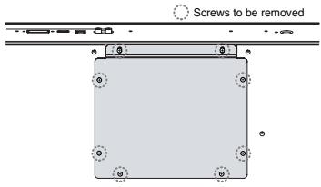
text_image
Screws to be removed- Insert the two tabs on the instrument into the holes of the expansion board so that the connectors of the instrument and expansion board are aligned.
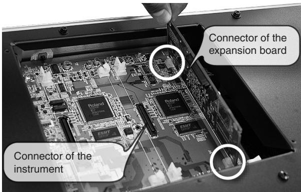
text_image
Connector of the expansion board Connector of the instrument* Do not touch any of the printed circuit pathways or connection terminals.
- Press in the expansion board in the direction shown by the photo.
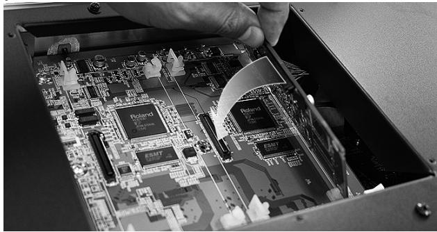
natural_image
Close-up of a hand inserting into an open circuit board with visible components (no text or symbols)* Never use excessive force when installing a circuit board. If it doesn't fit properly on the first attempt, remove the board and try again.
- Press firmly inward until the tabs on the instrument lock into the holes of the expansion board.
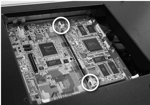
natural_image
Interior view of an electronic circuit board with visible components and two circled areas of interest (no text or symbols)- Use the screws that you removed in step 2 to fasten the cover back in place.
Removing an Expansion Board
To remove an expansion board, reverse the process by which you inserted it.
- Unlatch the Fantom-G's tabs.
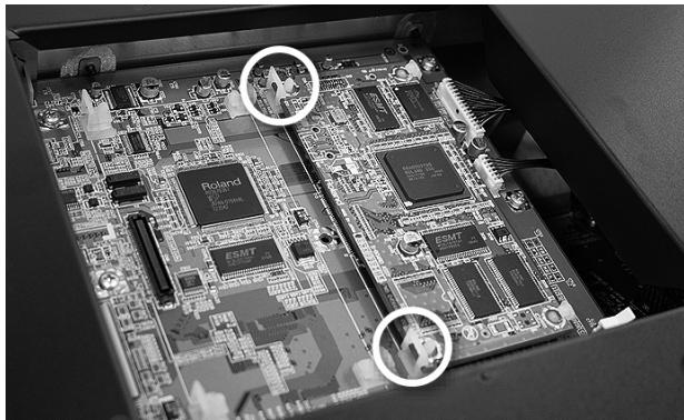
natural_image
Interior view of an electronic circuit board with multiple integrated circuits and a close-up of a device (no visible text or symbols)- Slowly raise the expansion board upright.
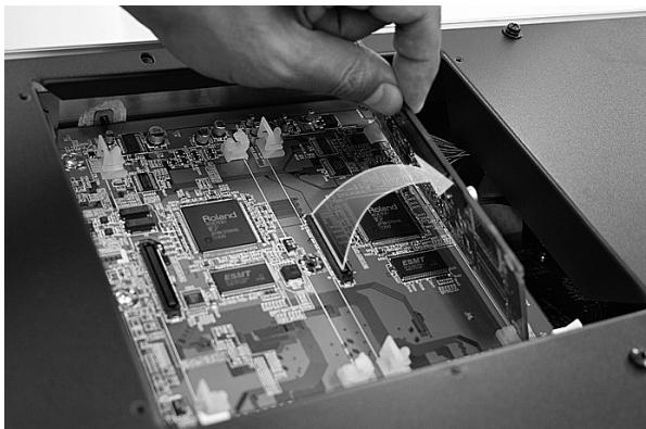
natural_image
Close-up of a hand inserting a circuit board into an open case (no visible text or symbols)-
Pull out the expansion board by reversing step 3 of the installation process.
-
Attach the cover by reversing step 2 of the installation process.
Configuring the Newly-installed Expansion Board
After you've finished installing an expansion board into the Fantom-G, you must perform the following procedure.
MEMO
You'll perform this procedure only once, the first time you turn on the power after inserting an expansion board.
- Turn on the power as described in "Turning On the Power" (p. 28).
- When the Fantom-G starts up, an install confirmation screen for the newly inserted expansion board will appear. Press [F8 (Execute)] to execute the install confirmation process.
If you decide to cancel, press [F7 (Cancel)].
NOTE
If the install confirmation screen does not appear when you start up for the first time, it is possible that the expansion board was not detected correctly. Reinstall the expansion board correctly.
NOTE
This process will require several minutes. Never turn off the power until this process has been completed.
- When the screen indicates that installation has been completed, turn the power off, and then on again.
This completes the installation process.
cf.
For details on using the expansion board, refer to the manual included with the expansion board.
(French Language for Canadian Safety Standard)
natural_image
Close-up of a hand inserting a component into an open circuit board (no visible text or symbols)natural_image
Interior view of an electronic circuit board with visible chips and components, no text or symbols present.natural_image
Interior view of an electronic circuit board with multiple integrated circuits and labeled components (no readable text or symbols)natural_image
Close-up of a hand inserting a circuit board into an open case, showing internal components and no visible text or symbols.Expanding the DIMM Memory
The Fantom-G comes with 32 MB of memory into which audio samples can be loaded. However, in some cases, 32 MB of memory will be insufficient for loading large amounts of data. In such a case, you will have to add separately sold memory (DIMM). Memory can be expanded up to 128/256/512 MB/1 GB.
Specifications of the expansion memory (DIMM) that can be used
Supports Unbuffered (non-Registered), PC133, CL=2/3, 128 MB, 256 MB, 512 MB, 1 GB (3.3 V)
Number of pins: 168-pin
Board height: 40 mm or less
NOTE
The Fantom-G is unable to use buffered (registered) DIMM memory.
NOTE
The Fantom-G has been confirmed to work with standard memory that meets the above specifications. However, we cannot guarantee that all memory of these specifications will work correctly. Please be aware that even with identical specifications, differences in the design of the memory module or the conditions of use may mean that a memory module may not be usable.
NOTE
Operation is not guaranteed for single samples larger than 512 MB.
Precautions for Expanding Memory
- Always turn the unit off and unplug the power cord before attempting installation of the memory DIMM board.
- To avoid the risk of damage to internal components that can be caused by static electricity, please carefully observe the following whenever you handle the board.
- Before you touch the board, always first grasp a metal object (such as a water pipe), so you are sure that any static electricity you might have been carrying has been discharged.
- When handling the board, grasp it only by its edges. Avoid touching any of the electronic components or connectors.
- Save the bag in which the board was originally shipped, and put the board back into it whenever you need to store or transport it.
- Use a Phillips screwdriver that is suitable for the size of the screw (a number 2 screwdriver). If an unsuitable screwdriver is used, the head of the screw may be stripped.
- To remove a screw, rotate the screwdriver counter-clockwise. To tighten the screws, rotate the screwdriver clockwise.
- Be careful that the screws you remove do not drop into the interior of the Fantom-G.
- Be careful not to cut your hand on the edge of the cover or the opening edge while removing the cover.
- Do not touch any of the printed circuit pathways or connection
terminals.
- Never use excessive force when installing a circuit board. If it doesn't fit properly on the first attempt, remove the board and try again.
- When circuit board installation is complete, double-check your work.
- Install only the specified memory DIMM board. Remove only the specified screws.
- When turning the unit upside-down, get a bunch of newspapers or magazines, and place them under the four corners or at both ends to prevent damage to the buttons and controls. Also, you should try to orient the unit so no buttons or con
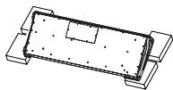
- When turning the Fantom-G8 upside-down, at least two persons are required to safely lift and turn the Fantom-G8. Make sure to have a firm grip, to protect yourself from injury and the instrument from damage.
- When turning the unit upside-down, handle with care to avoid dropping it, or allowing it to fall or tip over.
- Do not leave the bottom cover removed. After installation of the memory module is complete, be sure to replace the cover.
How to Expand the Memory
Install the memory module after removing the bottom panel cover.
- Before expanding the memory, turn off the power of the Fantom-G and all connected devices, and disconnect all cables, including the Power cord, from the Fantom-G.
- From the Fantom-G, remove only the screws shown in the following diagram, and detach the cover.
text_image
Screws to be removed Screws to be removed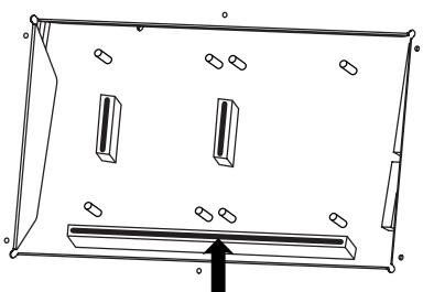
natural_image
Pure technical line drawing of a rectangular frame with internal compartments and mounting holes, no text or symbols present.- Press outward on the white clips at either end of the socket so they are in their downward position.
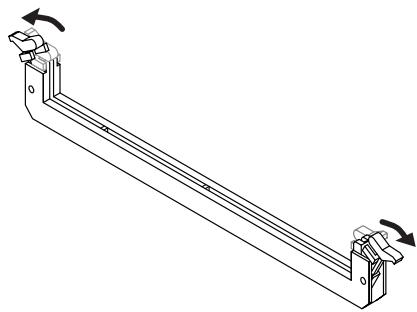
natural_image
Technical line drawing of a mechanical bracket with rotational arrows indicating motion (no text or symbols)- Paying attention to the location of the notches on the memory module and the correct orientation, insert the module vertically within the guides at either side of the socket.
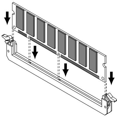
natural_image
Technical diagram of a rectangular electronic component with multiple slots and mounting brackets, showing downward force arrows (no text or symbols)TIP
If you have difficulty inserting the memory module, try tilting it a bit and inserting one end at a time.
- Move the white clips upward, and press them until the memory module is locked in place.
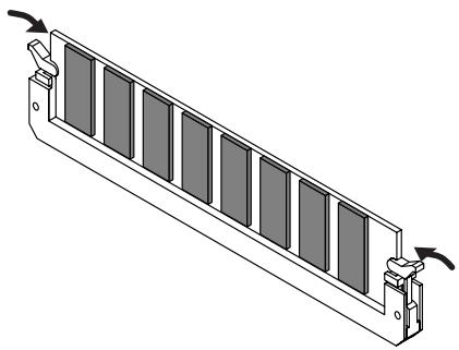
natural_image
Technical line drawing of a mechanical component with multiple slots and mounting brackets (no text or symbols)- Use the screws that you removed in step 2 to fasten the cover back in place.
Removing the Memory
To remove the memory module, reverse the installation procedure.
- Simultaneously press outward the white clips located at either end of the socket.
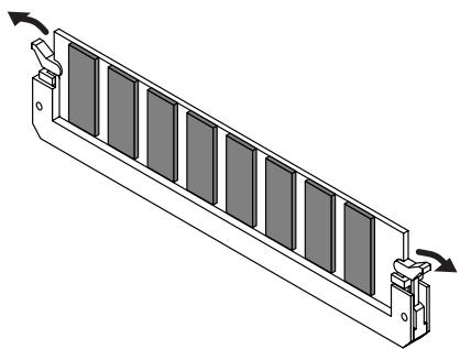
natural_image
Isometric diagram of a mechanical component with multiple slots and mounting brackets (no text or symbols)- Remove the memory module from the socket.
Checking that Memory is Installed Correctly
- Turn on the power, as described in "Turning On the Power" (p. 28).
- Press [MENU] to open the Menu window.
- Turn the VALUE dial or use [CURSOR] to select "System," and then press [ENTER].
-
Press [ENTER].
-
Press [F4 (Info)].
-
Press [F1 (Up)] or [F2 (Down)] to select "Memory Info." Verify that the screen correctly shows the amount of memory you installed.
-
Press [EXIT] to exit the System screen.
* If the correct amount of memory is not shown, it is possible that the memory is not being recognized properly. Turn off the power as described in “Turning Off the Power” (p. 28), and re-install the memory correctly.
About USB memory
The contents of DIMM memory will be lost when you turn off the power. The Fantom-G contains 50 M bytes of internal flash memory (internal memory), but if you've expanded the DIMM memory, a fully recorded project will be
too large to be saved in internal memory. In this case, you'll need to save the data in USB memory.
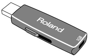
natural_image
Illustration of a Roland USB flash drive with USB port and USB cable (no text or symbols on device body)Unbuffered (non-Registered), PC133, CL=2/3, 128 MB, 256 MB, 512 MB, 1 GB (3.3 V)
Nombre de broches:168-pin
natural_image
Technical line drawing of a rectangular frame with internal compartments and mounting holes, featuring a black arrow pointing to a component (no text or symbols)natural_image
Technical line drawing of a mechanical bracket with two side supports and rotational arrows indicating motion (no text or symbols)natural_image
Technical diagram of a multi-panel electronic device with mounting brackets and downward arrows indicating assembly or alignment (no text or symbols present)natural_image
Technical line drawing of a mechanical component with multiple slots and mounting brackets (no text or symbols)natural_image
Technical line drawing of a mechanical component with multiple slots and directional arrows indicating motion (no text or symbols)If the Fantom-G does not function in the way you expect, first check the following points. If this does not resolve the problem, consult your dealer or a nearby Roland Service Station.
* If any sort of message is being displayed on the screen during an operation, refer to Error Messages (p. 322).
Problems Concerning the Entire Fantom-G
The power does not turn on.
A Make sure that the Fantom-G's AC cord is connected correctly to its power inlet and to the AC outlet (p. 25).
Issues Related to Sound
Turning the VOLUME knob doesn't change the volume.
A If you're using the DIGITAL OUT, the VOLUME knob will not change the volume. Adjust the "Master Level" (p. 297).
There is no sound.
A Check the following points.
- Is the power for connected amps and speakers turned on? Is the volume turned all the way down?
• Is the VOLUME knob turned all the way down?
• Have connections been made correctly? - Can you hear sound through headphones?
If there is sound in the headphones, it is possible that the connection cables are broken, or that your amp/mixer has malfunctioned. Check your cables and amp/mixer system once again. - If you do not hear sound when you play the keyboard, check whether the Local Switch is turned OFF. Make sure that the Local Switch parameter is turned on (p. 297).
- Have all tones in the patch been turned off? Turn the “Tone Switch” on → From the Single Play screen, press [F8 (Tone Sw/Sel)].
- Could the current part be set to External Part (external MIDI output)?
- The Part level settings may be too low. Access the Level parameter, and check the level of each part (p.134).
- Are the Effect settings correct? Check the Effect settings ON or OFF, the Effect Balance or Level. (p. 150).
- Are the settings for the output destination correct? Check the various output assign settings (p. 136).
- Is the Expansion Board properly installed? When selecting the settings that stipulate the use of EXP 1, 2 sound, check that the specified Expansion Board is installed properly in the specified slot (p. 308, p. 310).
- Has the volume been lowered by pedal operations or by MIDI messages (volume messages or expression messages) received
from an external MIDI device?
• Could the Favorite Level be set to 0? (p. 54)
TIP
In the case of Live/Studio mode, the value of volume messages (Volume) and expression messages (Expression) can be viewed in the Part Information window (p. 132).
• Have the samples been loaded correctly? (p. 264)
Q A specific Part does not sound...
A Check the following points.
- Has the volume level of the part been lowered?
Adjust the Level parameter to raise the volume of the part that is not heard (p. 134).
• Is the part being muted?
Set the Mute Switch parameter to "OFF" (p. 134).
Specific pitch ranges do not sound...
A Has a restricted range of notes been set?
If a specific range of notes does not sound, check the Key Range settings for the Patch Tone, the Live/Studio Set Part.
- Tone Key Range Key Range Lower/Upper parameter (p. 94)
- Part Key Range Key Range Lower/Upper parameter (p. 135)
The sound is distorted.
A Check the following points.
- Is an effect which distorts the sound being applied?
If the sound for a specific patch or part is distorted, lower the volume level on that part. - If all sounds are distorted, use the VOLUME knob to lower the volume level.
- Could the Output Gain be excessively high? In "System," check the "Sound" parameter.
Q Pitch is incorrect.
A Check the following points.
• Is the tuning of the Fantom-G incorrect?
Check the Master Tune parameter setting (p. 297).
- Has the pitch been changed by pedal operations or by Pitch Bend messages received from an external MIDI device?
TIP
In the case of Live/Studio mode, the value of Pitch Bend messages (Pitch Bend) can be viewed in the Part Information window (p. 132).
- Have the Coarse Tune or Fine Tune parameters been set for specific Parts?
Check the Coarse Tune parameter and Fine Tune parameter settings (p. 137).
- Check the Scale Tune setting. (System Setting: p. 300, Part Setting: p. 138)
The sound is interrupted.
A Sounds will be interrupted if more than 128 voices are used simultaneously.
- Reduce the number of Tones that you are using.
- Increase the Voice Reserve setting for parts that must not drop out. (p. 141)
When I play the keyboard, notes do not stop.
A Is the pedal polarity of the Hold Pedal reversed?
Check the Hold Pedal Polarity parameter setting (p. 291).
When I press a pad, the sound does not stop sounding.
A Could the [HOLD] pad be lit?
Press the [HOLD] pad once again so the light goes out.
The sound is interrupted when I switch studio sets in Studio mode.
A The Fantom-G can use multi-effects to apply a wide variety of effects, and when you switch studio sets, the multi-effect type specified by the patch will also change. In Studio mode, the sound may be interrupted when this occurs. If you want to switch sounds without interruption while you perform, please use Live mode or Single mode.
The sound is interrupted when I switch patches in Single mode or Live mode.
A If you turn the Patch Remain parameter (p. 298) "ON," you'll be able to switch patches without interrupting the sound. However, this function applies only to the most recently selected sound; notes of a sound selected prior to that will be interrupted.
When switching Patches in Single mode, the volume and other parameters set with Control Changes end up being reset.
A Set Control Remain parameter (p. 298) to "ON." Even once they have switched Patches, Control Change messages that have been received are carried forward, so even when switching a Patch whose level is turned all the way down by a Control Change volume message, the level remains unchanged.
If the Tone Delay time value is set to the note, then does the delay time not change beyond a fixed length when the tempo is slowed down?
A There is a maximum permissible value for the Delay Time parameter (p. 103). So, if the time setting is specified in terms of a note value, and the tempo is slowed down, this maximum permissible value will be reached, and it cannot be increased further. The upper time limit for each is the maximum value that can be set other than the numerical value for the beat.
Even when I set the Pan for a Patch completely to one side, sound still comes from the other channel...
A The Fantom-G's internal effects are in stereo, so if you have effects applied to a Patch, even if the Pan is set all the way to one side, you will still be able to hear sounds of the effect component from the other channel.
Sometimes, when playing legato, the pitch won't rise. Why is this?
A When the Legato Switch parameter (p. 105) is “ON,” and the Legato Retrigger parameter (p. 105) is “OFF,” and you hold down keys in the high register to play legato, the upper pitch limit of the wave may be exceeded, so that the pitch does not rise as far as you expect, but will stop rising at a certain point. Additionally, if differing upper pitch limits are used for the waves of a Patch that uses multiple tones, it may stop being heard in MONO. When making large pitch changes, set the Legato Retrigger parameter to “ON.”
The notes sound strange in the upper registers of the keyboard.
A Sometimes when playing the keys in the upper part of the Fantom-G's keyboard, the sound may stop, or the pitch may stop rising; or with certain keys, there may be intermittent noise. This occurs mainly when the Fantom-G's upper pitch limit is exceeded, so this issue doesn't arise in the ranges normally used. But, in any case, it does not indicate a malfunction.
The same patch sounds different depending on the sound generator mode.
A In Live/Studio mode, the parameters of each part of the Live/Studio Set can apply further modification to parameters such as pan, octave, and filter, relative to the settings specified by the patch. Thus, Patches in a Live/Studio Set may sound different than they do when heard in Single mode. To return these settings to their initial conditions, select the Patch after execute Factory Reset Temporary for the Live/Studio Set. (p. 284)
The volume level of the instrument connected to Fantom-G is too low.
A Check the following points.
- Could you be using a connection cable that contains a resistor? Use a connection cable that does not contain a resistor.
- Check the "Input Setting" (p. 258).
Issues Related to Effects
Effects not applied.
A Check the following points.
- The "PFX," "MFX1," "MFX2," "CHO," "REV" or "MASTER" effect switches located in the upper part of the PLAY screen may have been turned off.
Press [EFFECTS (ROUTING)] to turn them on. - Are the various effect settings correct? (p. 150)
- If the send level of each effect is set to 0, the effect will not be applied. Check the settings.
- Even with send levels to each effect set at 0, effects are not applied if the Multi-effects Output Level, the Chorus Level, or the Reverb Level is set to 0. Check each setting.
- If Output Assign is set to other than "MFX," the Multi-effects sound will not be output.
- Could the system parameter Master Reverb Level be set to 0?
The Modulation or other controller is always on.
A Check the Matrix Controller settings. (p. 109)
The Fantom-G allows you to use the Matrix Control to control Patches in real time. The Matrix Control functions as the control source for the Control Change and other MIDI messages received by the Fantom-G, and makes changes to the various Patch parameters based on these messages.
Depending on these settings, the Fantom-G may be responding to MIDI messages sent from external MIDI devices, and may result in the Patches sounding different than intended.
Raising the chorus or reverb send level for each part of a Live/Studio Set still does not cause the effect to be applied sufficiently.
Although you can make Send level settings to the Chorus and Reverb for each individual Part in a Live/Studio Set, these values only set the upper limit of the Chorus and Reverb Send levels for the Patch used. Accordingly, even when the value is set to the maximum of 127, if the Send level is lowered in the Patch being used, there will be no effect. If you want to apply the effect deeply, edit the settings of the patch.
Using the Matrix Control or other such means to control the LFO results in noise when the Pan is changed suddenly.
A Lower the change in speed (LFO Rate).
Due to the specialized processing used for the Pan, which alters the volume level in each of the left and right sides, sudden Pan movements causing rapid changes in these levels creates large changes in volume, and noise from this may be audible as a result.
Multi-effect 43: TAP DELAY or other delay time value is set to the note, and then the tempo is slowed down, does the delay time not change beyond a fixed length?
A Such Delay time settings have an upper limit, so if the upper limit of a value set to the note is exceeded when the tempo is retarded, that upper value cannot rise any further. The upper time limit for each is the maximum value that can be set other than the numerical value for the beat.
Issues Related to Saving Data
The Live/Studio Set sounds different than when it was written.
A Check the following points.
- If you have modified the settings of a patch used by a Live/Studio Set, or if the temporary patch of the Live/Studio Set has been modified by an external MIDI device, these patches must also be saved.
If patches used by a Live/Studio Set have been edited when you write that Live/Studio Set, the Fantom-G will display a message asking whether you want to discard these patches. In such cases, first save the patch (p. 88) or rhythm set (p. 116), and then save the Live/Studio Set (p. 148) again. - The Mastering Effect settings may have changed. (These settings are not stored as part of a Live set.)
- The MFX settings may have changed. (These settings are not stored as part of a Live set.)
An expansion board sound seems different from when I saved (wrote) it.
A If the expansion board is inserted in a different slot than when you saved the live set or studio set, it will not sound with the settings of when it was saved. You must insert the expansion board in the same slot as when you saved the live set or studio set.
Patches sound different than when written.
A Check the following points.
- If you used control changes from an external MIDI device to modify the sound, writing the sound will not save it in its modified state.
- The Mastering Effect settings may have changed. (These settings are not stored as part of a patch.)
The Arpeggio and D Beam controller settings in the Live/Studio Mode are different than those for the Live/Studio Set.
A Since the Fantom-G stores arpeggio and D Beam controller settings for each Live/Studio Set, it will operate according to the arpeggio and D Beam controller settings that were specified for each Live/Studio Set.
Issues Related to Sequencer
Standard MIDI files (SMF) a does not play back correctly.
A Check the following points.
- Has the Receive General MIDI/General MIDI 2 System On Switch been turned ON?
Set the Rx GM System ON/Rx GM2 System ON parameter (SYSTEM/MIDI) to "ON" (p. 299). - Are you trying to start playback from midway through the song?
The beginning of a GM score song contains a General MIDI/General MIDI 2 System On message. In some cases, a GM Score cannot be played back correctly unless this message is received. - Are you trying to play song data designed for the GS Format? Data created exclusively for the Sound Canvas Series may not play back properly on the Fantom-G.
After recording, the song does not sound when I play it back.
A Have the tracks been muted?
Defeat muting (p. 134).
The tempo is different than the last time I played back the song.
A If a song is played back after the tempo is changed, then the new tempo is not saved unless the song is saved to the user memory or USB memory. Conversely, the previous tempo will be erased when you save the song. When saving songs, carefully check the current tempo.
Sound Device Tones Are Switched Arbitrarily.
A Use the Microscope (p. 250) to check the following points.
- Has an unneeded program change been input?
- Were any mistakes made in setting the data MIDI channels when Program Change messages were input?
Data supposed to be present does not appear in microscope.
A Check the following points.
- In View Select (p. 252), is any data set not to be displayed?
After using a MIDI sequencer to play a song, sounds stopped playing, and no sound is played even when Program Changes are sent.
A It could be that a Bank Select in the song data that is not specified by the Fantom-G was encountered in the song. No sound is played if the tone group is not one designated by the Fantom-G with Bank Select MSB/LSB. Note that if you omit the Bank Select, and send only the Program Change, the tone in the currently selected group that has the specified Program Change number will play. Try resettling the tone using the panel controls. Furthermore, when selecting tones from an external MIDI device, be sure to send the Bank Select MSB/LSB and the Program Change as a single set for reliable reproduction. First sending the MSB and LSB (the order in which these are sent does not matter), followed by the Program Change. In some cases, you may be unable to hear any sound after playing the last song that was faded-out. This may be because the volume has been lowered by volume messages or expression messages. Check the value of these messages, and set them to appropriate values.
Performances are sluggish, or have interruptions.
A Problems of sluggish and interrupted performances can crop up very easily when the sequencer or sound generator used for the performance has to handle heavy data loads.
Main causes and possible corrective measures are considered below.
- Are more than 128 voices playing simultaneously? Reduce the number of voices. With certain sounds like continuous sounds with long releases, even though the actual sound may not be audible to you, processing for playing the sound is still underway, so in these cases as well, the performance data can differ from the actual number of voices being played.
TIP
In the Part Information window you can check the number of notes for which sound is actually being processed (p. 132).
- Are you using a Patch that uses a lot of LFO? Try changing to a different Patch. LFO processing invariably places a big load on the machine, so heavy use of the LFO slows down processing for the Fantom-G overall, which can end up having affecting the expression of sounds themselves.
- Is the data concentrated at the beginning of the beats in the sequence data?
Avoid overlapping data with the same timing by setting an offset of 1–2 tick instead. Data may easily become concentrated at the beginning of the beats in the song data when, for example, the song data is input using Step Recording, or if the data is quantized after being input with a keyboard in real time. Because of this, large amounts of data are sent to the Fantom-G, and the processing for expressing sounds becomes bogged down.
Troubleshooting
- Is there a Program Change at the point where the song performance is sluggish?
Change the position of the Program Change. When Program Changes are inserted in songs, processing time for switching patches increases, which may then cause the performance to become sluggish.
- Is there a System Exclusive message at the point where the song performance is sluggish?
Move the location of the data. System Exclusive messages contain large amounts of data, thus placing a heavy burden on sequencers and sound modules. Try repositioning data and changing System Exclusive messages to Control Changes for any data for which Control Changes can be substituted.
- Is there an Aftertouch or other such large Control Change at the point where the song performance is sluggish?
If the data is no longer needed, delete the data. In some cases, when using a keyboard that features aftertouch to input data, you may end up inputting huge amounts of data before realizing this is happening. Such large amounts of data can place an excessive load on your sequencer and sound module.
TIP
You can use the Phrase Modify operation Data Thin (p. 249) to thin out unwanted messages.
Issues Related to MIDI and External Devices
No Sound from connected MIDI device.
A Check the following points.
• In Live/Studio Mode
KBD switch (p. 61, p. 69)
* Could the Keyboard Switch be turned off for the external part that is transmitting data to your external MIDI device? (p. 135)
Exclusive messages are not received.
A Check the following points.
- Is the instrument set to receive Exclusive messages? Set the Rx Exclusive parameter to "ON" (p. 299).
- Does the Device ID number of the transmitting device match the Device ID number of the Fantom-G? Check the Device ID parameter (p. 299).
I connected an external sequencer or MIDI keyboard to the MIDI IN connector, and attempted to play a Fantom-G rhythm set, but there was no sound. Why?
A Check to make sure that the MIDI Transmit channel of the external MIDI device and the Fantom-G's MIDI Receive channel are matched.
When the Bend Range for a Patch is increased (48), the pitch does not rise sufficiently, even when a MIDI Pitch Bend message is received.
A While Patch Bend Ranges can be set anywhere between 0 and 48, when certain Waves in which the pitch is raised (in the + direction) are used, the pitch may stop rising at a fixed point, rather than continuing to go up. Although a value of 12 is ensured for the upper limit of raised pitches, use caution when setting the Bend Range above this figure.
Issues Related to Sampling
External input sound cannot be heard/volume is too low.
A Check the following points.
• Could [MIX IN] be unlit? Press [MIX IN] so it is lit.
- The level of the external input may be lowered. When you sample, use the EXT SOURCE "VOLUME" knob to adjust the level appropriately. Hold down [SHIFT] and press [MIX IN] to access the Input Setting screen, and check the Level settings.
- The volume of the device connected to AUDIO INPUT may be lowered. Adjust it to an appropriate level.
- Are the audio cables connected correctly? Check the connections.
• An audio cable may be broken.
- Could you be using an audio cable with a built-in resistor? Use a connection cable that does not contain a resistor (e.g., Roland PCS series).
External input sound is not stereo/is not monaural.
A Check the following points.
- Stereo Switch parameter (p. 260) may be set to monaural. - Hold down [SHIFT] and press [MIX IN] to access the Input Setting screen. Could the Input Select parameter be set to “LINE IN L,” or “Microphone”?
Q Mic sound is not output/is too weak.
A Check the following points.
- Is the mic cable connected correctly? Check the connection.
• The mic cable may be broken.
- The input source may be set to something other than mic. Hold down [SHIFT] and press [MIX IN] to access the Input Setting screen, and set "Input Select" to "Microphone."
- The mic level may have been lowered. When sampling, use the EXT SOURCE "LEVEL" knob to adjust the level appropriately.
• Could you have connected a condenser mic?
If you're using a condenser mic, you'll need to provide phantom power.
Turn the MIC/GUITAR switch "PHANTOM ON." (p. 24)
- Could the MIC/GUITAR switch be in a position "GUITAR"?
Set the INPUT gain select switch to "PHANTOM ON" or "PHANTOM OFF." (p. 24)
Can't record a sample.
A Check the following points.
• Is there enough memory capacity?
If there is insufficient sample memory, a message of "Sample Memory Full!" will appear when you attempt to sample. (p. 264)
Erase unneeded samples to increase the amount of free space. If there is still not enough, install additional memory (DIMM modules). (p. 312, p. 314)
Q Sampled sound contains excessive noise or distortion.
A Check the following points.
• Is the input level appropriate?
If the input level is too high, the sampled sound will be distorted. If it is too low, noise will be heard. When sampling, turn the LEVEL knob in the Sampling Standby screen (p. 260) to adjust the level while watching the level meter displayed in the upper part of the display. Adjust the level so that the “CLIP” indication in the upper right of the display does not appear.
- Are the effect settings appropriate?
Some types of effect may increase the level louder than the original sample, or may intentionally distort the sound. Some effects will also cause noise to be emphasized.
Temporarily turn off effects, and check whether the sample itself contains noise or distortion. Then adjust the effect settings appropriately.
- Are multiple samples being played simultaneously?
Even if the level of each individual sample is appropriate, simultaneously playing multiple samples may cause the overall level to be excessively high, causing distortion. Lower the level of each sample so that the sound is not distorted.
Can't save sampled data.
A Check the following points.
- It may be that there is insufficient space in internal memory or USB memory.
Issues Related to a USB memory
USB memory is not detected.
The files are not shown.
A Check the format of your USB memory. (p. 284)
- The Fantom-G can use USB memory that has been formatted as FAT.
If your USB memory was formatted using any other method, please re-format it using FAT.
Can't save to USB memory.
A Check the following points.
• Could the USB memory be write protected?
- Is there sufficient free space on the USB memory?
Issues Related to a USB connection
The Fantom-G is not recognized by my computer.
A You must connect the Fantom-G to a computer whose USB port supports USB 2.0 Hi-Speed connections.
If an incorrect operation is performed, or if processing could not be performed as you specified, an error message will appear. Refer to the explanation for the error message that appears, and take the appropriate action.
| Message | Meaning | Action |
| Empty Sample! | The sample contains no data. | Select a sample that contains data. |
| Empty Song! | The song has not been recorded, and therefore cannot be played. | Select a song that contains data. |
| File Name Duplicate | A file with the same name already exists. | Delete the file bearing the same name from the disk, and if overwriting and saving the data, merely save the file. If you do not want to delete the file with the same name from the disk, either save the file with a different name. |
| File Not Found! | The file was not found in USB memory. | Save the file once again in USB memory. |
| Illegal File! | The Fantom-G cannot use this file. | — |
| Memory Damaged! | The contents of internal memory may have been damaged. | Please perform the Factory Reset operation.If this does not resolve the problem, please contact your dealer or the nearest Roland Service Center. |
| Memory Full! | Saving is not possible because there is insufficient space in the internal memory or USB memory. | Delete unneeded data. |
| MIDI Buffer Full! | An unusually large amount of MIDI data was received, and could not be processed. | Reduce the amount of MIDI messages that are being transmitted. |
| MIDI Offline! | The MIDI IN connection was broken. | Check that there is no problem with the MIDI cable connected to the Fantom-G's MIDI IN, and that the MIDI cable was not disconnected. |
| No More Phrase Numbers! | No more phrases can be saved. One project can handle a maximum of 2,000 phrases. | Please delete unneeded phrases. |
| No More Sample Numbers! | The sample cannot be divided any further. | Erase unneeded samples in order to allocate 256 or more consecutive sample numbers. |
| Since fewer than 256 consecutive sample numbers are vacant, no further sampling is possible. | ||
| No More Song Numbers! | No more songs can be saved. One project can handle a maximum of fifty songs. | Please delete unneeded songs. |
| Now Playing! | Since the Fantom-G is playing, this operation cannot be executed. | Stop playback before you execute the operation. |
| Permission Denied! | The file is protected. | — |
| Playback Tempo Range Over | Tempo values exceed the allowable limit, and data is created in which the closest time available within the allowable range is specified. | — |
| Read Error! | Failed to load data from USB memory. | Make sure that USB memory is correctly connected. |
| It may be that the file is damaged. | Do not use this file. | |
| This file cannot be loaded since its format is incorrect. | Do not use this file. | |
| Rec Length Too Short! | The recording length is too short. | Lengthen the duration of the recording. |
| Rec Over Flow | Since a large amount of recorded data was input all at once, it could not be processed correctly. | Reduce the amount of recorded data. |
| Sample Length Too Short! | The sample is too short, and cannot be edited correctly. | If the sample is extremely short, editing may not produce the desired result. |
| Sample Memory Full! | Since there is insufficient sample memory, no further sampling or sample editing is possible. | Erase unneeded samples. |
| Song Format Error | This song is damaged. | This song cannot be used. |
| Song Full | Since the maximum number of notes that can be recorded in a song or phrase has been exceeded, no further recording/editing is possible. | Use the phrase edit Delete or Erase commands to remove unneeded data from the song/phrase that you are recording/editing. |
| Song Not Found | The selected song cannot be found. | — |
| System Memory Damaged! | It is possible that the contents of system memory have been damaged. | Please execute a Factory Reset.If this does not resolve the problem, contact your dealer or a nearby Roland service center. |
| USB Memory Not Ready! | USB memory is not connected. | Connect USB memory. |
| USB Offline! | The USB cable is not connected. | Check that there is no problem with the USB cable connected to the Fantom-G, and that the USB cable was not disconnected. |
| Write Error! | Failed to write data to USB memory. | Make sure that USB memory is correctly connected. |
| The file or the USB memory itself is write protected. | Make sure that the file or the USB memory is not write protected. | |
| You Cannot Erase This Message | This message cannot be erased. | — |
| You Cannot Move This Message | This message cannot be moved. | — |
MIDI (Musical Instruments Digital Interface) is a standard specification that allows musical data to be exchanged between electronic musical instruments and computers. MIDI With a MIDI cable connecting MIDI devices that are equipped with MIDI connectors, you can play multiple instruments with a single keyboard, have multiple MIDI instruments perform in ensemble, program the settings to change automatically to match the performance as the song progresses, and more.
If you mainly use the Fantom-G as a standalone keyboard instrument, you may really not need to know much at all about MIDI.
However, the following MIDI-related information is provided so you can play the Fantom-G using an external MIDI device, or master other advanced techniques.
About MIDI Connectors
The Fantom-G is equipped with the three types of MIDI connectors, each which works differently.
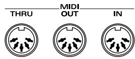
MIDI IN Connector
This connector receives MIDI messages that are transmitted from external MIDI devices. The Fantom-G can receive these messages to play notes or select sounds, etc.
MIDI OUT Connector
This connector transmits MIDI messages to external MIDI devices. The Fantom-G's MIDI OUT connector is used for sending the performance data of the keyboard controller section as well as data used for saving various settings and patterns.
MIDI THRU Connector
MIDI messages received at MIDI IN are re-transmitted without change from this connector to an external MIDI device. Use this in situations such as when you use multiple MIDI devices simultaneously.
MIDI Channels and Multi-timbral Sound Generators
MIDI transmits many types of data over a single MIDI cable. This is made possible by the concept of MIDI channels. MIDI channels allow messages intended for a given instrument to be distinguished from messages intended for another instrument. In some ways, MIDI channels are similar to television channels. By changing the channel on a television set, you can view the programs that are being broadcast by different stations. In the same way, MIDI also allows a device to select the information intended for that device out of the variety of information that is being transmitted to it.
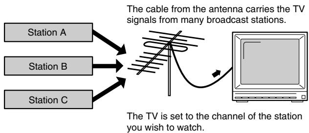
flowchart
graph TD
    A["Station A"] --> C["TV Signal"]
    B["Station B"] --> C
    D["Station C"] --> C
    C --> E["Radio Signal"]
    E --> F["TV Broadcast"]
    style E fill:#f9f,stroke:#333,stroke-width:2px
    note right of E: The cable from antenna carries the TV signals from many broadcast stations.
    note right of F: The TV is set to the channel of the station you wish to watch.
MIDI uses sixteen channels; 1 through 16. Set the receiving device so that it will receive only the channel that it needs to receive.
Example:
Set the Fantom-G to send Channel 1 and Channel 2, then set sound module A to receive only Channel 1 and sound module B only Channel 2. With this setup, you can get an ensemble performance, with, for example, a guitar sound from sound module A and bass from sound module B.
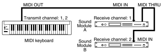
flowchart
graph TD
    A["MIDI keyboard"] -->|Transmit channel: 1, 2| B["MIDI OUT"]
    B --> C["MIDI IN"]
    C --> D["MIDI THRU"]
    D --> E["Receive channel: 1"]
    E --> F["Sound Module A"]
    F --> G["Receive channel: 2"]
    G --> H["Sound Module B"]
When used as a sound module, the Fantom-G can receive on up to sixteen MIDI channels. Sound modules like the Fantom-G which can receive multiple MIDI channels simultaneously to play different sounds on each channel are called multi-timbral sound modules.
General MIDI
General MIDI is a set of recommendations which seeks to provide a way to go beyond the limitations of proprietary designs, and standardize the MIDI capabilities of sound generating devices. Sound generating devices and music files that meet the General MIDI standard bear the General MIDI
logo (GENERAL). Music files bearing the General MIDI logo can be played back using any General MIDI sound generating unit to produce essentially the same musical performance.
General MIDI 2
The upwardly compatible General MIDI 2 (GENERAL MIDI2) recommendations pick up where the original General MIDI left off, offering enhanced expressive capabilities, and even greater compatibility. Issues that were not covered by the original General MIDI recommendations, such as how sounds are to be edited, and how effects should be handled, have now been precisely defined. Moreover, the available sounds have been expanded. General MIDI 2 compliant sound generators are capable of reliably playing back music files that carry either the General MIDI or General MIDI 2 logo.
In some cases, the conventional form of General MIDI, which does not include the new enhancements, is referred to as "General MIDI 1" as a way of distinguishing it from General MIDI 2.
| Function... | Transmitted | Recognized | Remarks | |
| Basic Channel | Default Changed | 1-161-16 | 1-161-16 | |
| Mode | Default Messages Altered | Mode 3Mono, Poly********** | Mode 3Mode 3, 4 (M = 1) | *2 |
| Note Number : True Voice | 0-127********** | 0-1270-127 | ||
| Velocity | Note On Note Off | OO | OO | |
| After Touch | Key's Channel's | OO | O *1O *1 | |
| Pitch Bend | O | O *1 | ||
| Control Change | 0, 32156, 387101164656667687172737475767778808182838491931-31, 33-9596, 9798, 99100, 101102-119 | O *1O O O O O O O O O O O O O O O O O O O O O O O O O O O O O O O O O O O O O O O O O O O O O O O O O O O O O O O O O O O O O O O O O O O O O O O O O O O O O O O O O O O O O O O O O O O O O O O O O O O O O | O *1O *1O *1O O O O O *1O *1O *1O *1O *1O *1O *1O *1O *1O *1O *1O *1O *1O *1O *1O *1O *1O *1O *1O *1O *1O *1O *1O *1O *1O *1O *1O *1O *1O *1O *1O *1O *1O *1O ***(Tone 1 Level)O (Tone 2 Level)O (Tone 3 Level)O (Tone 4 Level)O (Reverb)O (Chorus)O O (Tone 1 Level)O (Tone 2 Level)O (Tone 3 Level)O (Tone 4 Level)O (Reverb)O (Chorus)O (Reverb)O (Reverb)O (Reverb)O (Reverb)O (Reverb)O (Reverb)O (Reverb)O (Reverb)O (Reverb)O (Reverb)O (Reverb)O (Reverb)O (Reverb)O (Reverb)O (Reverb)O (Reverb)O (Reverb)O (Reverb)O (Reverb)O (Reverb)O (ReVerb)O (Reverb)O (Reverb)O (Reverb)O (Reverb)O (Reverb)O (Reverb)O (Reverb)O (Reverb)O (Reverb)O (Reverb)O (Reverb)O (Reverb)O (Reverb)O (Reverb)O (Reverb)O (Reverb)O (Reverb)O (Reverb)O (Reverb)O (Reveb)O (Reverb)O (Reverb)O (Reverb)O (Reverb)O (Reverb)O (Reverb)O (Reverb)O (Reverb)O (Reverb)O (Reverb)O (Reverb)O (Reverb)O (Reverb)O (Reverb)O (Reverb)O (Reverb)O (Reverb)O (Reverb)O (Reverb)O (Reverb)O (Reverb)O (Reverb)O (Reverb)O (Reverb)O (Reverb)O (Reverb)O (Reverb)O (Reverb)O (Reverb)O (Reverb)O (Reverb)O (Reverb)O (Reverb)O (Reverb)O (Reverb)O (Reverb)O (Reverb)O (Reverb)O (Reverb)O (Rerverb)O (Reverb)O (Reverb)O (Reverb)O (Reverb)O (Reverb)O (Reverb)O (Reverb)O (Reverb)O (Reverb)O (Reverb)O (Reverb)O (Reverb)O (Reverb)O (Reverb)O (Reverb)O (Reverb)O (Reverb)O (Reverb)O (Reverb)O (Rerbode)O (Reverb)O (Reverb)O (Reverb)O (Reverb)O (Reverb)O (Reverb)O (Reverb)O (Reverb)O (Reverb)O (Reverb)O (Reverb)O (Reverb)O (Reverb)O (Reverb)O (Reverb)O (Reverb)O (Reverb)O (Reverb)O (Reverb)O (Recomb)O (Recomb)O (Recomb)O (Recomb)O (Recomb)O (Recomb)O (Recomb)O (Recomb)O (Recomb)O (Recomb)O (Recomb)O (Recomb)O (Recomb)O (Recomb)O (Recomb)O (Recomb)O (Recomb)O (Recomb)O (Recomb)O (Recomb)O (Reweb)O (Reweb)O (Reweb)O (Reweb)O (Reweb)O (Reweb)O (Reweb)O (Reweb)O (Reweb)O (Reweb)O (Reweb)O (Reweb)O (Reweb)O (Reweb)O (Reweb)O (Reweb)O (Reweb)O (Reweb)O (Reweb)O (Reweb)O (ReWeb)O (ReWeb)O (ReWeb)O (ReWeb)O (ReWeb)O (ReWeb)O (ReWeb)O (ReWeb)O (ReWeb)O (ReWeb)O (ReWeb)O (ReWeb)O (ReWeb)O (ReWeb)O (ReWeb)O (ReWeb)O (ReWeb)O (ReWeb)O (ReWeb)O (ReWeb)O (Reweb)O (Reweb)O (Reweb)O (Reweb)O (Reweb)O (Reweb)O (Reweb)O (Reweb)O (Reweb)O (Reweb)O (Reweb)O (Reweb)O (Reweb)O (Reweb)O (Reweb)O (Reweb)O (Reweb)O (Reweb)O (Reweb)O (Reverb)O (Reverb)O (Reverb)O (Reverb)O (Reverb)O (Reverb)O (Reverb)O (Reverb)O (Reverb)O (Reverb)O (Reverb)O (Reverb)O (Reverb)O (Reverb)O (Reverb)O (Reverb)O (Reverb)O (Reverb)O (Reverb)O (Reweb)O (Reweb)O (Reweb)O (Reweb)O (Reweb)O (Reweb)O (Reweb)O (Reweb)O (Reweb)O (Reweb)O (Reweb)O (Reweb)O (Reweb)O (Reweb)O (Reweb)O (Reweb)O (Reweb)O (Reweb)O (Reweb)O (Reveb)O (Reveb)O (Reveb)O (Reveb)O (Reveb)O (Reveb)O (Reveb)O (Reveb)O (Reveb)O (Reveb)O (Reveb)O (Reveb)O (Reveb)O (Reveb)O (Reveb)O (Reveb)O (Reveb)O (Rerverb)O (Rerverb)O (Rerverb)O (Rerverb)O (Rerverb)O (Rerverb)O (Rerverb)O (Rerverb)O (Rerverb)O (Rerverb)O (Rerverb)O (Rerverb)O (Rerverb)O (Rerverb)O (Rerverb)O (Rerverb)O (Rerverb)O (Reverb)O (Reverb)O (Reverb)O (Reverb)O (Reverb)O (Reverb)O (Reverb)O (Reverb)O (Reverb)O (Reverb)O (Reverb)O (Reverb)O (Reverb)O (Reverb)O (Reverb)O (Reverb)O (Reverb)O (Reverb)O(Reverb)O(Reverb)O(Reverb)O(Reverb)O(Reverb)O(Reverb)O(Reverb)O(Reverb)O(Reverb)O(Reverb)O(Reverb)O(Reverb)O(Reverb)O(Reverb)O(Reverb)O(Reverb)O(Reverb)O(Reverb)O(Reverb)O(Reverb)O (Reverb)O(Reverb)O(Reverb)O(Reverb)O(Reverb)O(Reverb)O(Reverb)O(Reverb)O(Reverb)O(Reverb)O(Reverb)O(Reverb)O(Reverb)O(Reverb)O(Reverb)O(Reverb)O(Reverb)O(Reverb)O(Reverb)O (Reverb)O (Reverb)O (Reverb)O (Reverb)O (Reverb)O (Reverb)O (Reverb)O (Reverb)O (Reverb)O (Reverb)O (Reverb)O (Reverb)O (Reverb)O (Reverb)O (Reverb)O (Reverb)O (Reverb)O (Reverb)O (Reverb)O(Reverb)O(Resverb)O(Resverb)O(Resverb)O(Resverb)O(Resverb)O(Resverb)O(Resverb)O(Resverb)O(Resverb)O(Resverb)O(Resverb)O(Resverb)O(Resverb)O(Resverb)O(Resverb)O(Resverb)O(Resverb)O(Resverb)O(Resverb)O(Resverb)O(Reverb)O(Reverb)O(Reverb)O(Reverb)O(Reverb)O(Reverb)O(Reverb)O(Reverb)O(Reverb)O(Reverb)O(Reverb)O(Reverb)O(Reverb)O(Reverb)O(Reverb)O(Reverb)O(Reverb)O(Reverb)O(Reverb)O(Resverb)O(Resverb)O(Resverb)O(Resverb)O(Resverb)O(Resverb)O(Resverb)O(Resverb)O(Resverb)O(Resverb)O(Resverb)O(Resverb)O(Resverb)O(Resverb)O(Resverb)O(Resverb)O(Resverb)O(Resverb)O (Reverb)O(Reverb)O(Reverb)O(Reverb)O(Reverb)O(Reverb)O(Reverb)O(Reverb)O(Reverb)O(Reverb)O(Reverb)O(Reverb)O(Reverb)O(Reverb)O(Reverb)O(Reverb)O(Reverb)O(Reverb)O(Reverb)O(Resverb)O(O)(Resverb)O(O)(Resverb)O(O)(Resverb)O(O)(Resverb)O(O)(Resverb)O(O)(Resverb)O(O)(Resverb)O(O)(Resverb)O(O)(Resverb)O(O)(Resverb)O(O)(Resverb)O(O)(Resverb)O(O)(Resverb)O(O)(Resverb)O(O)(Resverb)O(O)(Resverb)O(O)(Resverb) | |
| Program Change : True Number | O *1********** | O *1O -127 | Program No. 1-128 | |
| System Exclusive | O | O *1 | ||
| System Common : Song Position : Song Select : Song Select : Song Select : Song Select : Song Select : Song Select : Song Select : Song Select : Song Select : Song Select : Song Select : Song Select : Song Select : Song Select : Song Select : Song Select : Song Select : Song Select : Song Select : Song Select : Song Select : Song Select : Song Select : Song Select : Song Select : Song Select : Song Select : Song Select : Song Select : Song Select : Song Select : Song Select : Song Select : Song Select: XXXX | XXXX | XXXX | XXXX | |
| System Common : Clock : Command : Commands : Commands : Commands : Commands : Commands : Commands : Commands : Commands : Commands : Commands : Commands : Commands : Commands : Commands : Commands : Commands : Commands : Commands : Commands : Commands : Commands : Commands : Commands : Commands : Commands : Commands : Commands : Commands : Commands : Commands : Commands : Commands : Commands : Commands : Commands : Commands : Commands : Commands : Commands : Commands : Commands : Commands : Commands : Commands : Commands : Commands : Commands : Commands : Commands : Commands : Standards : Standards : Standards : Standards : Standards : Standards : Standards : Standards : Standards : Standards : Standards : Standards : Standards : Standards : Standards : Standards : Standards : Standards : Standards : Standards : Standards : Standards : Standards : Standards : Standards : Standards : Standards : Standards : Standards : Standards : Standards : Standards : Standards : Standards : Standards : Standards : Standards : Standards : Standards : Standards : Standards : Standards : Standards : Standards : Standards : Standards : Standards : Standards : Standards : Standards : Standard : Standard : Standard : Standard : Standard : Standard : Standard : Standard : Standard : Standard : Standard : Standard : Standard : Standard : Standard : Standard : Standard : Standard : Standard : Standard : Standard : Standard : Standard : Standard : Standard : Standard : Standard : Standard : Standard : Standard : Standard : Standard : Standard : Standard : Standard : Standard : Standard : Standard : Standard : Standard : Standard : Standard : Standard : Standard : Standard : Standard : Standard : Standard : Standard : Standard :Standard : Standard : Standard : Standard : Standard : Standard : Standard : Standard : Standard : Standard : Standard : Standard : Standard : Standard : Standard : Standard : Standard : Standard : Standard : Standard : Standard : Standard : Standard : Standard : Standard : Standard : Standard : Standard : Standard : Standard : Standard : Standard : Standard : Standard : Standard : Standard : Standard : Standard : Standard : Standard : Standard : Standard : Standard : Standard : Standard : Standard : Standard : Standard : Standard : Standard : Normal : Normal : Normal : Normal : Normal : Normal : Normal : Normal : Normal : Normal : Normal : Normal : Normal : Normal : Normal : Normal : Normal : Normal : Normal : Normal : Normal : Normal : Normal : Normal : Normal : Normal : Normal : Normal : Normal : Normal : Normal : Normal : Normal : Normal : Normal : Normal : Normal : Normal : Normal : Normal : Normal : Normal : Normal : Normal : Normal : Normal : Normal : Normal : Normal : Normal : N/A : N/A : N/A : N/A : N/A : N/A : N/A : N/A : N/A : N/A : N/A : N/A : N/A : N/A : N/A : N/A : N/A : N/A : N/A : N/A : N/A : N/A : N/A : N/A : N/A : N/A : N/A : N/A : N/A : N/A : N/A : N/A : N/A : N/A | ||||
| Aux Messages : All Sound Off : Reset All Controllers : Reset All Controllers : Reset All Controllers : Reset All Controllers : Reset All Controllers : Reset All Controllers : Reset All Controllers : Reset All Controllers : Reset All Controllers : Reset All Controllers : Reset All Controllers : Reset All Controllers : Reset All Controllers : Reset All Controllers : Reset All Controllers : Reset All Controllers : Reset All Controllers : Reset All Controllers : Reset All controllers : Reset All controllers : Reset All controllers : Reset All controllers : Reset All controllers : Reset All controllers : Reset All controllers : Reset All controllers : Reset All controllers : Reset All controllers : Reset All controllers : Reset All controllers : Reset All controllers : Reset All controllers : Reset All controllers : Reset All controllers : Reset All controllers : Reset All controllers : Reset All controllers : Reset All controllers : Reset All controllers : Reset All controllers : Reset All controllers : Reset All controllers : Reset All controllers : Reset All contours : Reset All contours : Reset All contours : Reset All contours : Reset All contours : Reset All contours : Reset All contours : Reset All contours : Reset All contours : Reset All contours : Reset All contours : Reset All contours : Reset All contours : Reset All contours : Reset All contours : Reset All contours : Reset All contours : Reset All contours : Reset All contours : Reset All contours : Reset All contours : Reset All contours : Reset All contours : Reset All contours : Reset All contours : Reset All contour : Reset All contours : Reset All contours : Reset All contours : Reset All contours : Reset All contours : Reset All contours : Reset All contours : Reset All contours : Reset All contours : Reset All contours : Reset All contours : Reset All contours : Reset All contours : Reset All contours : Reset All contours : Reset All contours : Reset All contours : Reset All contours : Reset All contours : Reset All contours : Reset All contours : Reset All contours : Reset All contours : Reset All contours : Reset All volumes : Reset All volumes : Reset All volumes : Reset All volumes : Reset All volumes : Reset All volumes : Reset All volumes : Reset All volumes : Reset All volumes : Reset All volumes : Reset All volumes : Reset All volumes : Reset All volumes : Reset All volumes : Reset All volumes : Reset All volumes : Reset All volumes : Reset All volumes : Reset All volumes : Reset All volumes : Reset All volumes : Reset All volumes : Reset All volumes : Reset All volumes : Reset All volumes : Reset All volume : Reset All volume : Reset All volume : Reset All volume : Reset All volume : Reset All volume : Reset All volume : Reset All volume : Reset All volume : Reset All volume : Reset All volume : Reset All volume : Reset All volume : Reset All volume : Reset All volume : Reset All volume : Reset All volume : Reset All volume : Reset All volume : Reset All volume : Reset All volume : Reset All volume : Reset All volume : Reset All volume : Reset All volume : Reset All volumes : Reset All volumes : Reset All volumes : Reset All volumes : Reset All volumes : Reset All volumes : Reset All volumes : Reset All volumes : Reset All volumes : Reset All volumes : Reset All volumes : Reset All volumes : Reset All volumes : Reset All volumes : Reset All volumes : Reset All volumes : Reset All volumes : Reset All volumes : Reset All volumes : Reset All volumes : Reset All volumes : Reset All volumes : Reset All volumes : Reset All volumes : Reset All values : Reset All values : Reset All values : Reset All values : Reset All values : Reset All values : Reset All values : Reset All values : Reset All values : Reset All values : Reset All values : Reset All values : Reset All values : Reset All values : Reset All values : Reset All values : Reset All values : Reset All values : Reset All values : Reset All values : Reset All values : Reset All values : Reset All values : Reset All values : Reset All values : Reset All value : Reset All value : Reset All value : Reset All value : Reset All value : Reset All value : Reset All value : Reset All value : Reset All value : Reset All value : Reset All value : Reset All value : Reset All value : Reset All value : Reset All value : Reset All value : Reset All value : Reset All value : Reset All value : Reset All value : Reset All value : Reset All value : Reset All value : Reset All value : Reset All value : Reset All values : Reset All values : Reset All values : Reset All values : Reset All values : Reset All values : Reset All values : Reset All values : Reset All values : Reset All values : Reset All values : Reset All values : Reset All values : Reset All values : Reset All values : Reset All values : Reset All values : Reset All values : Reset All values : Reset All values : Reset All values : Reset All values : Reset All values : Reset All values : Reset All vials : Reset All vials : Reset All vials : Reset All vials : Reset All vials : Reset All vials : Reset All vials : Reset All vials : Reset All vials : Reset All vials : Reset All vials : Reset All vials : Reset All vials : Reset All vials : Reset All vials : Reset All vials : Reset All vials : Reset All vials : Reset All vials : Reset All vials : Reset All vias : Reset All vias : Reset All vias : Reset All vias : Reset All vias : Reset All vias : Reset All vias : Reset All vias : Reset All vias : Reset All vias : Reset All vias : Reset All vias : Reset All vias : Reset All vias : Reset All vias : Reset All vias : Reset All vias : Reset All vias : Reset All vias : Reset All vias : Reset All vialvias : Reset All vials : Reset All vials : Reset All vials : Reset All vials : Reset All vials : Reset All vials : Reset All vials : Reset All vials : Reset All vials : Reset All vials : Reset All vials : Reset All vials : Reset All vials : Reset All vials : Reset All vials : Reset All vials : Reset All vials : Reset All vials : Reset All vials : Reset All vialvials : Reset All vials : Reset All vials : Reset All vials : Reset All vials : Reset All vials : Reset All vials : Reset All vials : Reset All vials : Reset All vials : Reset All vials : Reset All vials : Reset All vials : Reset All vials : Reset All vials : Reset All vials : Reset All vials : Reset All vials : Reset All vials : Reset All vials : Reset Allvials : Reset Allvials : Reset Allvials : Reset Allvials : Reset Allvials : Reset Allvials : Reset Allvials : Reset Allvials : Reset Allvials : Reset Allvials : Reset Allvials : Reset Allvials : Reset Allvials : Reset Allvials : Reset Allvials : Reset Allvials : Reset Allvials : Reset Allvials : Reset Allvials : Reset Allvials : Reset All vials : Reset All vials : Reset All vials : Reset All vials : Reset All vials : Reset All vials : Reset All vials : Reset All vials : Reset All vials : Reset All vials : Reset All vials : Reset All vials : Reset All vials : Reset All vials : Reset All vials : Reset All vials : Reset All vials : Reset All vials : Reset All vials : ResetAll vials : ResetAll vials : ResetAll vials : ResetAll vials : ResetAll vials : ResetAll vials : ResetAll vials : ResetAll vials : ResetAll vials : ResetAll vials : ResetAll vials : ResetAll vials : ResetAll vials : ResetAll vials : ResetAll vials : ResetAll vials : ResetAll vials : ResetAll vials : ResetAll vials : ResetAll vials : ResetTotal vials: ResetTotal vials: ResetTotal vials: ResetTotal vials: ResetTotal vials: ResetTotal vials: ResetTotal vials: ResetTotal vials: ResetTotal vials: ResetTotal vials: ResetTotal vials: ResetTotal vials: ResetTotal vials: ResetTotal vials: ResetTotal vials: ResetTotal vials: ResetTotal vials: ResetTotal vials: ResetTotal vials: ResetTotal vials: ResetTotal vials : ResetTotal vials: ResetTotal vials: ResetTotal vials: ResetTotal vials: ResetTotal vials: ResetTotal vials: ResetTotal vials: ResetTotal vials: ResetTotal vials: ResetTotal vials: ResetTotal vials: ResetTotal vials: ResetTotal vials: ResetTotal vials: ResetTotal vials: ResetTotal vials: ResetTotal vials: ResetTotal vials: ResetTotal vials: Reset Total vials: ResetTotal vials: ResetTotal vials: ResetTotal vials: ResetTotal vials: ResetTotal vials: ResetTotal vials: ResetTotal vials: ResetTotal vials: ResetTotal vials: ResetTotal vials: ResetTotal vials: ResetTotal vials: ResetTotal vials: ResetTotal vials: ResetTotal vials: ResetTotal vials: ResetTotal vials: ResetTotal vials: ResetTotal vials: Reset Total vials : ResetTotal vials: ResetTotal vials: ResetTotal vials: ResetTotal vials: ResetTotal vials: ResetTotal vials: ResetTotal vials: ResetTotal vials: ResetTotal vials: ResetTotal vials: ResetTotal vials: ResetTotal vials: ResetTotal vials: ResetTotal vials: ResetTotal vials: ResetTotal vials: ResetTotal vials: ResetTotal vials: ResetTotal vials: ResetTure: 100% 100% 100% 100% 100% 100% 100% 100% 100% 100% 100% 100% 100% 100% 100% 100% 100% 100% 100% 100% 100 % 100% 100% 100% 100% 100% 100% 100% 100% 100% 100% 100% 100% 100% 100% 100% 100% 100% 100% 100% 100%. | ||||
Mode 1 : OMNI ON, POLY
Mode 3 : OMNI OFF, POLY
Mode 2 : OMNI ON, MONO
Mode 4 : OMNI OFF, MONO
O: Yes
X : No
| Function... | Transmitted | Recognized | Remarks | |
| Basic Channel | Default Changed | All channel X | All channel 1-16 | There is no specific basic channel. |
| Mode | Default Messages Altered | X X********** | X X | |
| Note Number : True Voice | 0-127********** | 0-127 0-127 | ||
| Velocity | Note On Note Off | O O | O O | |
| After Touch | Key's Channel's | O O | O *1 O *1 | |
| Pitch Bend | O | O *1 | ||
| Control Change | 0-119 | O | O *1 | |
| Program Change : True Number | O********** | O *1 0-127 | ||
| System Exclusive | O | O *1 | ||
| System Common : Puzzle Request | Quarter Frames Song Position Song Select Tune Request | O *1 O *1 X O | O *2 O *1 X O | |
| System Real Time : Commands | O *1 O *1 | O *1 O *1 | ||
| Aux Messages : All Sound Off Reset All Controllers Local On/Off All Notes Off Active Sensing System Reset | O O X *2 O *3 O X | O O X O (123-127) *3 O X | ||
| Notes | *1 O X is selectable.*2 Not stored/transmitted when received, but can be created and transmitted using Microscope.*3 Mode Messages (123-127) are recorded and transmitted, after all currently sounding notes are turned off. The All Note Message itself is not recorded or transmitted. However, it can be created in Microscope and transmitted. | |||
Mode 1 : OMNI ON, POLY
Mode 2 : OMNI ON, MONO
O : Yes
Mode 3 : OMNI OFF, POLY
Mode 4 : OMNI OFF, MONO
X : No
Fantom-G6/G7/G8:
Synthesizer Keyboard (Conforms to General MIDI 2 System)
Keyboard
[G6] 61 keys (with velocity and channel aftertouch)
[G7] 76 keys (with velocity and channel aftertouch)
[G8] 88 keys (Progressive Hammer action II Mechanism, Ivory feel, and channel aftertouch)
Sound Generator Section
Maximum Polyphony
128 voices (shared with the sampling section)
Parts
16 parts (Internal) + 16 parts (External) + 2 parts (ARX) +
24 parts (Audio Track)
Wave Memory
256 M bytes (16-bit linear equivalent)
Waveforms
2,230
Preset Memory
Patches: 1,668 + 256 (GM2)
Rhythm Sets: 64 + 9 (GM2)
Live Sets: 512
Studio Sets: 8
User Memory (per 1 project)
Patches: 512
Rhythm Sets: 64
Sample Sets: 128
Live Sets: 512
Studio Sets: 128
Effects
Patch Multi-Effects
(PFX): 16 systems, 76 types
Multi-Effects
(MFX): 2 systems, 78 types
Chorus: 1system, 3 types
Reverb: 1system, 10 types
Input Effects: 1system, 6 types
Mastering Effects: 1system, 3-band compressor
Sampling Section
Data Format
16-bit linear (File Type: .WAV/.AIFF)
Sampling Frequency
44.1 kHz (fixed)
Maximum Sampling Time
- When sampling memory isn't expanded (32 MB)
mono: 360 sec. approx., stereo: 180 sec. approx. - When sampling memory is expanded with DIMM (1 GB)
mono: 202 min. approx., stereo: 101 min. approx.
Number of Samples (per 1 project)
2,000
Sequencer Section
Tracks
MIDI tracks (Internal/External/ARX): max.128
Audio tracks: max.24
Tempo track: 1
Beat track: 1
Resolution
480 TPQN
Tempo
5.00–300.00
Song (per 1 project)
50
Phrase (per 1 project)
2,000
Note Capacity (per 1 project)
approx. 1,000,000 notes
Song Length
9,998 measures
Recording Method
Realtime recording, Step recording
Others
Arpeggiator
128
Arpeggio Sets
128
RPS Sets
64
Rhythm Pattern Sets
64
Chord Memory
128
Chord Memory Sets
128
Display
Graphic Type, 8.5inch, TFT Wide VGA(800 x 480 dots), backlit LCD (Color)
Pads
16 pads, Velocity and Polyphonic Aftertouch sensitive
Controllers
Pitch Bend/Modulation Lever
Control Knob x 4
Control Slider x 8
Assignable Switch x 2
D Beam Controller
Connectors
Headphones Jack: stereo 1/4 inch phone type
A (MIX) Output Jacks (L/MONO, R): 1/4 inch TRS phone type
B Output Jacks (L, R): 1/4 inch phone type
Input Jacks (L/MONO/MIC, R): 1/4 inch phone type
Mic./Guitar Input Jacks: 1/4 inch phone type/XLR type
(Phantom power) (Hi-Z)
Hold Pedal Jack (Half Pedal recognition)
Control Pedal Jack (assignable) x 2
MIDI Connectors (IN, OUT, THRU)
USB Computer Connector (supports file transfer (mass storage class) and Audio/MIDI)
USB Mouse Connector
Digital Audio Interface (COAXIAL INPUT/OUTPUT)
AC Inlet
Expansion Slots
- Expansion of sound generator
ARX expansion boards: 2 slots
- Expansion of sampling memory
DIMM: 1 slot (supports Unbuffered (non-Registered), PC133, CL=2/3, 128 MB, 256 MB, 512 MB, 1 GB (3.3 V))
External Storage Device
USB Flash Memory
Power Supply
AC 117 V, AC 230 V, AC 240 V (50/60 Hz)
AC 220 V (60 Hz)
Power Consumption
30 W
Dimensions
[G6] 1,066 (W) x 411 (D) x 142 (H) mm 42 (W) x 16-3/16 (D) x 5-5/8 (H) inches
[G7] 1,278 (W) x 411 (D) x 142 (H) mm 50-3/8 (W) x 16-3/16 (D) x 5-5/8 (H) inches
[G8] 1,396 (W) x 502 (D) x 183 (H) mm 55 (W) x 19-13/16 (D) x 7-1/4 (H) inches
Weight
[G6] 14.5 kg / 32 lbs
[G7] 16.6 kg / 36 lbs 10 oz
[G8] 33.6 kg / 74 lbs 2 oz
Accessories
Owner's Manual
Quick Start Guide
Sound List
Driver Installation Guide
CD-ROM (Editor, USB MIDI driver)
Power Cord
Options
Expansion Board: ARX Series
Keyboard Stand: KS-18Z (Fantom-G6/G7/G8), KS-G8 (Fantom-G8)
Pedal Switch: DP series
Foot Switch: BOSS FS-5U
Expression Pedal: EV-5
USB Memory: M-UF1G
Microphone: DR series
Headphone: RH-200
* In the interest of product improvement, the specifications and/or appearance of this unit are subject to change without prior notice.
A
AC Inlet 24
Accent Rate (Arpeggio Accent Rate) 79
Aftertouch Sens 292
Aftertouch Sens (Aftertouch Sensitivity) 292
AIFF 289
Alternate Pan Depth 101, 125
Amp 131,270
Analog Feel (Analog Feel Depth) 90
Appearance 304
Arabian Scale 138,300
Arpeggio 22,78,146,193
Arpeggio Hold 146
Arpeggio Number 146,193
Arpeggio Part Group 146
Arpeggio Part Number 146
Arpeggio Part Switch 136
Arpeggio Switch 146
Assign Type 118
Assignable 22,75
Assignable Switch 23
Attack 160
Attack Time Offset 91
Audio 36
AUDIO INPUT MIC/GUITAR Jack 24
Audio Rec Channel (Audio recording channel) 231
Audio Rec Mode (Audio recording mode) 231
Audio Track 37
Auto Chop 273
Auto Track 222
B
Backup Project 282
BANK 189
Bank (Rhythm set bank) 192
Beam Trigger Mode 73,143
Beam Trigger Pad 73,143
Beam Trigger Velo (Beam Trigger Velocity) 73,143
Beat Change 236
Beat Indicator Mode 297
Beat Track 37,219,236
Bend Mode 97
Bend Mode Control 97
Bias 101
Bias Direction 101
Bias Level 101
Bias Position 101
BOOKMARK 198
Booster 94
Booster 1&2, 3&4 (Booster Gain 1&2, 3&4) 94
C
CD 255
Change Channel 246
Change Duration 247
Change Velocity 245
Channel Aftertouch 251
Chop 272
Chord Form 81-82, 146, 193
Chord Memory 22,146,193
Chord Memory Function 81
Chord Switch 146
Chorus 36,159
Chorus Level 153, 156
Chorus Output Assign 153, 156
Chorus Output Select 153, 156
Chorus Send Level 74,144
Chorus Sw 153,156
Chorus Type 153, 156
Clear 239
Clock Source 295
Coarse Tune 137
Compare 89,117
Compare Function 87,115
Continuous Hold Pedal 291
CONTROL 23
Control 1–4 Source .... 109
Control Aftertouch (Control Aftertouch Switch) 147
Control Bender (Control Pitch Bend Switch) 147
Control Change 251
Control Destination 1–4 (Matrix Control Destination 1–4) .... 109
Control Hold Pedal (Control Hold Pedal Switch) 147
Control Knobs 1–4 ...... 23
Control Modulation (Control Modulation Switch) 147
Control Pedal 77
Control Pedal 1 Assign 291
Control Pedal 1 Panel Switch Assign 291
Control Pedal 1 Polarity 291
Control Pedal 1, 2 (Control Pedal 1, 2 Switch) .... 147
Control Pedal 2 Assign 291
Control Pedal 2 Panel Switch Assign 291
Control Pedal 2 Polarity 291
Control Remain (Control Remain Switch) 298
Control Sens 1–4 (Matrix Control Sens 1–4) .... 111
Control Setting 51,142
Control Sliders 1–8 ...... 23
Control Tone 1–4 (Tone Control Switch 1–4) .... 111
Copy 234, 243, 253
Count In 223,231
Create 252
Create Project 282
Ctrl Switch 147
Cursor 23,40
Cutoff 74,144
Cutoff Frequency 123
Cutoff Offset 90
Cutoff Velocity Curve 99,123
Cutoff Velocity Sens 99,123
D
D Beam 22,143
D Beam Assign Source 291
D Beam Controller 72-73
D Beam Sens (D Beam Sensitivity) 291
D Beam Switch 143
D Beam: ASSIGNABLE 145
D Beam: PAD TRIGGER 143
D Beam: SOLO SYNTH 143
Data Thin 249
DEC 23,41
Default File Type 301
Delay Time (LFO1/LFO2 Delay Time) 103
Delete 234, 243, 265
Delete Phrase 215
Destination 1–4 (Multi-Effects Control Destination 1–4) .... 157
Device ID (Device ID Number) 299
DIGITAL IN/OUT Connectors (S/P DIF COAXIAL) 24
Digital/USB Input Level 301
DIMM Memory 35
Direction 129, 191
DISPLAY 23
Drop Format 296
Dst 243
Duplicate 215
Dynamic Pad 23,146,292
E
Edit 234
Effect 36
EFFECT SW 199
EFFECTS (ROUTING) 23
Emphasis 269
Empty Sample! 322
Empty Song! 322
ENTER 23
Envelope 32
Equal Temperament 138,300
Erase 242,252
EXIT 23
EXP 1 23
EXP 2 23
EXPANSION 23
Expansion boards 35
Expression (Receive Expression Switch) 141
External Bank Select LSB 135
External Bank Select MSB 135
External Level 135
External Pan 135
External Program Number (External Program Change Number) 135
F
F1 40
Factory Data 35
Factory Reset 284
Fade Mode (LFO1/LFO2 Fade Mode) 104
Fade Time (LFO1/LFO2 Fade Time) 104
FAVORITE 22,202
Favorite Level 55
Favorite Screen 54
File Name Duplicate 322
File Not Found! 322
Filter Type 74,98,122,144
Font 57
FOOT PEDAL CTRL (CONTROL) 1, 2 Jack 24
Format USB memory 284
Function Button 23,40
FXM 92,120
FXM Color 92
FXM Depth 92
FXM Switch 92
G
Gap Time 302
General 89,117,129
GM 47,52
GM2 47,52
Grid Quantize Strength 224
Grid Resolution 224
GUITAR (Hi-Z) 24
H
HOLD 22-23,78,188
Hold Bend 97
HOLD Jack 24
Hold Pedal Polarity 291
|
Illegal File! 322
Import 303
Import Audio 287
Import BMP 288
Import Phrase 213
Import Song 213
Import Text 56,288
INC 23,41
INDIVIDUAL 1–4 Jacks 24
Info 302
Init 148
INPUT 22
Input Effect 36
Input Effect Setup 259
Input Quantize 223
Input Select 231,301
Input Setting 258
Input/Sampling 301
Insert 233,244
Internal Memory 35
J
JUMP 22
Just Temperament 138,300
K
KBD 61
Key Range 135
Key Trigger (Arpeggio Key Trigger) 79
Key Trigger (LFO1/LFO2 Key Trigger) 104
Keyboard 22,292
Keyboard Fade Width Lower 94
Keyboard Fade Width Upper 95
Keyboard Mode 143
Keyboard Range Lower 94
Keyboard Range Lower (Part Keyboard Range Lower) 135
Keyboard Range Upper 94
Keyboard Range Upper (Part Keyboard Range Upper) 135
Keyboard Switch 61, 69, 135
Keyboard Velocity 292
Keyboard Velocity (Arpeggio Keyboard Velocity) 79
Keyboard Velocity Curve 292
Keyboard Velocity Sens (Keyboard Velocity Sensitivity) 292
Knob 145
Knob 1–4 Assign 76,293
Knob 1–4 Settings 76
Knob 4 Assign 294
Knob Assign 1-4 145
Knob Assign Select 293
Knob Assign Source 293
Knob Slider Mode 293
Knob/Slider 293
KS-18Z 27
KS-G8 27
L
Layer 62
Layer Edit Screen 64
Legato 140
Legato Retrigger (Legato Retrigger Switch) 105
Legato Switch 105
Level 74,144,160
Level (Sample tone level) 191
Level Velocity Curve 124
Level Velocity Curve (TVA Level Velocity Curve) 100
Level Velocity Sens 124, 131
Level Velocity Sens (TVA Level Velocity Sensitivity) 100
Level/Pan 134-135
LFO 74
LFO (Low Frequency Oscillator) 32
LFO End Step 104
LFO Osc 1 Pitch Depth 74,143
LFO Osc 1 Pulse Width Depth 73,143
LFO Osc 2 Pitch Depth 74,143
LFO Osc 2 Pulse Width Depth 73,143
LFO Rate 74,144
LFO Step Type 104
LFO1/2 102-103
LFO1/LFO2 Delay Time Key Follow 103
LINE Jack (L, R) 24
LINE LEVEL knob 24
LIST/EDIT 23
LIVE 22
Live Mode 33, 39, 58, 151
Live Play (Layer/Split) Screen 58–59, 61
Live Set 33,60
Live Set Control Channel 299
Live Set Memo 132
Live Set Name 132
Live Set Part Mixer Screen 63
Load 214,264
Load All 264
Load Project 280
Local Switch 297
Loop 22,208
Loop Switch 223
Loop Waveform 88,116
M
Magic Control 294
MAGIC CTRL (Magic Control) 23
Marker 208
Master Key Shift 298
Master Level 297
Master Reverb Level 297
Master Tune 297
Mastering 160
Mastering Effect 36,160
Matrix Control Settings (Control 1–4) ...... 109
Memory Damaged! 322
Memory Full! 322
Menu 23,280
Metronome 297
Metronome Level 297
Metronome Mode 297
Metronome Sound 297
MFX 36
MFX Chorus Send Level (Multi-Effects Chorus Send Level) 155
MFX Output Assign (Multi-Effects Output Assign) 156
MFX Output Level (Multi-Effects Output Level) 155
MFX Reverb Send Level (Multi-Effects Reverb Send Level) 155
MFX Sw (Multi-Effects Switch) 155
MFX Type (Multi-Effects Type) 155
MFX/PFX Parameter 161
MFX1-2 158
MIC/GUITAR LEVEL knob 24
Microscope 250
MIDI 36,299
MIDI Buffer Full! 322
MIDI Clock 295
MIDI Connectors (IN, OUT, THRU) 24
MIDI Filter 141
MIDI Offline! 322
MIDI Phrase 214
MIDI Phrase List 214
MIDI Track 37
MIDI TX SW 198
Misc 107
MIX IN 22
Mix In Switch 301
Mix/Parallel 298
Mixer Screen 207
MMC Mode 295
MMC Output (MMC Output Switch) 295
MODE 22
Modulation Lever 23
Mono 140
Mono/Poly 105
Monophonic 50
Motif (Arpeggio Motif) 79
Move 233,253
MP3 255
MTC 295
MTC Error Level 296
MTC Frame Rate 295
MTC Offset Time Frame 296
MTC Offset Time Hour 296
MTC Offset Time Minute 296
MTC Offset Time Second 296
MTC Sync Output (MTC Sync Output Switch) 295
Multi 158
Multi-effect 36
Multi-Effects Control 158
MUTE 206
Mute Group 118, 129, 191, 195
Mute Switch 134
N
Name 42,132
No More Phrase Numbers! 322
No More Sample Numbers! 322
No More Song Numbers! 322
Non-Drop Format 296
Normalize 270
Note 251
Note Number 195-196
Now Playing! 322
Number / Name 192
Number / Name (Arpeggio set number) 193
Number / Name (Chord memory set number) 193
Number / Name (Sample set number) 191
NUMERIC 23,188
0
OCT 22
Octave Range (Arpeggio Octave Range) 79
Octave Shift 90,137
Offset 139
Offset (LFO1/LFO2 Offset) 103
One Shot Mode 118
One-shot Waveform 88,116
OSC 1/2 Coarse Tune 74,144
OSC 1/2 Fine Tune 74,144
OSC 1/2 Pulse Width 73,143
OSC 1/2 Waveform 73,143
OSC Sync Switch 74,144
OSC2 Level 74,144
Index
Output ...... 102, 125, 131
OUTPUT A (MIX) Jacks (L (MONO), R) 24
Output Assign 210
OUTPUT B Jacks (L, R) 24
Output Gain 298
Output/EFX 136
P
PAD 23
Pad Aftertouch Sens (Pad Aftertouch Sensitivity) 292
Pad Assign Source 292
Pad Exchange 190
PAD MODE 188
Pad Mode 23,43,292
Pad Note Number 192
Pad Roll Resolution 292
Pad Sens (Pad Sensitivity) 292
PAD SETTING 23,190
Pad Trigger 22,73
Pad Velocity 191-192, 292
Pan (Sample tone pan) 191
Pan Depth (LFO1/LFO2 Pan Depth) 104
Part 34
Part Attack Time Offset 139
Part Chorus Send Level 136, 152, 155
Part Coarse Tune 137
Part Cutoff Offset 139
Part Decay Time Offset 139
Part EFX1 Send Level (Expansion part effect 1: Send Level) .... 137
Part EFX2 Send Level (Expansion part effect 2: Send Level) .... 137
Part Fine Tune 137
Part Group 34
Part Info 132
Part Legato Switch 140
Part Level 134, 152, 155
Part MFX Select 155
Part Mono/Poly 140
PART MUTE 200
Part Octave Shift 137
Part Output Assign 136, 153, 155
Part Output Level 136, 152, 155
Part Pan 134
Part Pitch Bend Range 138
Part Portamento Switch 138
Part Portamento Time 138
Part Release Time Offset 140
Part Resonance Offset 139
Part Reverb Send Level 137, 152, 155
Part Scale Tune C-B 138
PART SELECT 200
Part Transpose 137
Part Velocity Sens Offset 136
Part Vibrato Delay 139
Part Vibrato Depth 139
Part Vibrato Rate 139
Part View 51,133
Part Voice Reserve 141
Patch 23,33,47,84
Patch Bank 134
Patch Category 89
Patch Coarse Tune 90
Patch Finder 48
Patch Fine Tune 90
Patch Initialize 87
Patch Level 89,152,155
Patch MFX 36
PATCH MFX SW 199
Patch multi-effect 36
Patch Name 89,132
Patch Number 134
Patch Parameters 89
Patch Priority 90
Patch Pro Edit 86,114,127
Patch Remain (Patch Remain Switch) 298
Patch Scale Tune for C-B 300
Patch Tone Copy 87
Patch Type 134
Patch Zoom Edit 84,112,126
PEAK Indicator 22
Pedal/D Beam 291
Permission Denied! 322
PFX 36,111,125,131
PFX (Patch Multi-Effects) 157
PFX Chorus Send Level (Patch Multi-Effects Chorus Send Level) 152, 155
PFX Control 157
PFX Output Level (Patch Multi-Effects Output Level) 152, 155
PFX Reverb Send Level (Patch Multi-Effects Reverb Send Level) 152, 155
PFX Sw 152
PFX Sw (Patch Multi-Effects Switch) 154
PFX Type (Patch Multi-Effects Type) 152, 154
PHANTOM OFF 24
PHANTOM ON 24
Phase Lock (Phase Lock Switch) 142
PHONES Jack 24
Phrase 220
Phrase Edit 238
Phrase Edit Screen 238
Phrase Loop 92,119,130
Phrase Modify Menu 239
Phrase Number 194
Phrase Preview 49
Phrases 36-37
Pitch 96,121,130,137
Pitch Bend 23
Pitch Bend Range Down 96
Pitch Bend Range Up 96
Pitch Depth (LFO1/LFO2 Pitch Depth) 104
Pitch Env (Pitch Envelope) 97, 121
Pitch Env Depth 97
Pitch Env Level 0–4 97, 122
Pitch Env Time 1 Velocity Sens 96,121
Pitch Env Time 1–4 ...... 97, 121
Pitch Env Time 4 Velocity Sens 97,121
Pitch Env Time Key Follow 97
Pitch Env Velocity Sens 96,121
Pitch/Pitch Env 96,121
PLAY 23
Play 238
Play Mode 195
Playback Tempo Range Over 322
Poly 140
Poly Aftertouch 251
Portamento 106
Portamento Mode 106
Portamento Start 106
Portamento Switch 106
Portamento Time 106
Portamento Type 106
POWER ON Switch 24
Power Up Mode 302
Pre Sample Time 301
Preset 47,52,60,67
Preset data 35
Preview 300
Preview 1–4 Note Number .... 301
Preview 1–4 Velocity 301
Preview Mode 300
Program Change 251
Project 35,280
PRST 47,52,60,67
Q
Quantize 240
R
Random Pan Depth 101, 124
Random Pitch Depth 96
Range (Solo synth range) 74,144
Range Max 75
Range Max (D Beam Range Upper) 145
Range Min 75
Range Min (D Beam Range Lower) 145
Rate (LFO1/LFO2 Rate) 103
Rate Detune (LFO1/LFO2 Rate Detune) 103
Ratio 160
Read Error! 322
Realtime Controller 75-76
Realtime Erase 225
Realtime Recording 222
Realtime Time Stretch 92,119,130
REC 23
Rec End Point 223
Rec End Point (Recording end point) 231
Rec End Switch 223
Rec End Switch (Recording end switch) 231
Rec Length 223
Rec Length (Recording length) 231
Rec Length Too Short! 322
Rec Mode 223
Rec Over Flow 322
Rec Start Point 223
Rec Start Point (Recording start point) 231
Receive Bank Select (Receive Bank Select Switch) 141,299
Receive Bender (Receive Pitch Bend Switch) 141
Receive Channel 134
Receive Channel Pressure (Receive Channel Pressure Switch) 141
Receive Exclusive (Receive System Exclusive Switch) 299
Receive GM1 System On (Receive GM System On Switch) 299
Receive GM2 System On (Receive GM2 System On Switch) 299
Receive GS Reset (Receive GS Reset Switch) 299
Receive Hold-1 (Receive Hold 1 Switch) .... 141
Receive Modulation (Receive Modulation Switch) 141
Receive Pan (Receive Pan Switch) 141
Receive Polyphonic Key Pressure (Receive Polyphonic Key Pressure Switch) 141
Receive Program Change (Receive Program Change Switch) 141,299
Receive Switch 134
Receive Volume (Receive Volume Switch) 141
Recording Select 224
Redo 217
Index
Rehearsal Function 225
Relative Level 125
Release 160
Release Time Offset 91
Remote Keyboard Sw (Remote Keyboard Switch) 299
Remove 55
Remove Bank 55
Remove Text 57
Resolution 240
Resonance 74,98,123,144
Resonance Offset 91
Resonance Velocity Sens 99,123
Rest 227
Restore Project 283
Reverb 36,159
Reverb Level 153, 156
Reverb Output Assign 153,156
Reverb Send Level 74,144
Reverb Sw 153, 156
Reverb Type 153, 156
RHYTHM 192
Rhythm Key Initialize 115
Rhythm Level (Rhythm Set Level) 117
Rhythm Pad Part Group 146
Rhythm Pad Part Number 146
Rhythm Pad Part Switch 136
Rhythm Pattern 196
Rhythm Pattern Set Number 196
RHYTHM PTN 196
Rhythm Set 33,52,112
Rhythm Set Initialize 115
Rhythm Set Name 117
Rhythm Set Parameter 117
Rhythm Tone 119
Rhythm Tone Copy 115
Rhythm Tone Name 118
Ring Modulator 94
ROLL 23,189
Rolled Chord 82,146
Rolled Chord Type 82,146
Routing 151, 154
RPS 194
RPS Set Number 194
S
S1 23
S1/S2 Switch Settings 77
S2 23
SAMPLE 23
Sample Edit 266
Sample Length Too Short! 322
Sample List 263
Sample Memory Full! 322
Sample Number 191
Sample Number L (Mono) 130
Sample Number R 130
SAMPLE PAD 191
Sample Pad Part Number 146
Sample Pad Part Switch 136
Sample Parameters 268
Sample Set 33,53,126
Sample Set Initialize 127
Sample Set Level 129
Sample Set Name 129
Sample Set Parameter 129
Samples 36-38
SAMPLING 23
Sampling Section 38
Save 216,254,274
Save All 216,274
Save As Project 281
Save As SMF 256
Save Project 281
Scale Tune 138,300
Scale Tune Switch 300
Screen Saver 301
Screen Saver Time 301
Screen Saver Type 301
Sens 1–4 (Multi-Effects Control Sensitivity 1–4) .... 158
SEQUENCER 22
Sequencer Auto Track 222
Set Song 56
Setting 160
SHIFT 23
Shift Clock 248
Shortcut 44
Shuffle Rate 224
Shuffle Rate (Arpeggio Shuffle Rate) 79
Shuffle Resolution 224
Shuffle Resolution (Arpeggio Shuffle Resolution) 79
SINGLE 22,46
Single Mode 33, 39, 46, 151
Single Play Screen 46
Skip Back Sampling 262
Skip Back Time 302
SKIPBACK 23
Slider 145
Slider 1-8 Assign 76,145,293
Slider 1–8 Settings 76
Slider 8 Assign 294
Slider Assign Select 293
Slider Assign Source 293
SMF 37,212,256
SMF List 212
Soft Through (Soft Through Switch) 299
Solo Synth 22,73
Solo/Porta 105
Song 23,36,218,228,232
Song Clear 211, 218, 235
Song Delete 210
Song Edit 232
Song Edit Screen 232
Song Format Error 322
Song Full 322
Song Not Found 322
Song Play 204-205
Song Play Screen 205
Song Util 235
Sound 297
Source 1–4 (Multi-Effects Control Source 1–4) .... 157
Split 62
Split Frequency High 160
Split Frequency Low 160
Standard MIDI File 37
Startup 302
Step 1–64 (LFO Step 1–64) ...... 104
Step Back 227
Step LFO 102,104
Step Recording 226
STOP 23
Stretch Tune Depth 90
Structure Type 1 & 2, 3 & 4 92
STUDIO 22
Studio Mode 33,39,66,154
Studio Play Screen 66-68
Studio Set 33,67–68
Studio Set Control Channel 299
Studio Set Memo 132
Studio Set Name 132
Style (Arpeggio Style) 78
Switch S1/S2 146,294
Switch S1/S2 Assign 77,146,294
Switch S1/S2 Assign Mode 146,294
Switch S1/S2 Assign Source 294
Sync Mode 295
Sync Output (Sync Output Switch) 295
Sync/Temp 295
System 283
System Control 1–4 Source 301
System Ctrl 301
System Exclusive messages 251
System Memory Damaged! 322
System Write 290
T
TEMPO 23
Tempo Change 236
Tempo Rec Switch 223
Tempo Sync (Wave Tempo Sync) 130
Tempo Track 37,235
TEMPO/VALUE 23
Temporary Area 35
Threshold 160
Tie 227
Time Stretch 271
Timing 241
TMT 92
TMT Control Switch 95
TMT Velocity Control (TMT Velocity Control Switch) 95
Tone 32
Tone Chorus Send Level 125, 131, 152, 154
Tone Coarse Tune 96
Tone Coarse Tune (Rhythm Tone Coarse Tune) 121
Tone Coarse Tune (Sample Tone Coarse Tune) 130
Tone Delay 107
Tone Delay Mode 107
Tone Delay Time 108
Tone Env Mode 108
Tone Env Mode (Rhythm Tone Envelope Mode) 118
Tone Fine Tune 96
Tone Fine Tune (Rhythm Tone Fine Tune) 121
Tone Fine Tune (Sample Tone Fine Tune) 130
Tone Initialize 87
Tone Level 100
Tone Level (Rhythm Tone level) 124
Tone Level (Sample Tone level) 131
Tone On/Off 50
Tone Output Assign 125, 131, 152, 154
Tone Output Level 125, 131, 152, 154
Tone Pan 101
Tone Pan (Rhythm Tone Pan) 124
Tone Pan (Sample Tone Pan) 131
Tone Pan Key Follow 101
Tone Pitch Bend Range (Rhythm Tone Pitch Bend Range) 118
Tone Random Pitch Depth 121
Tone Receive Bender (Tone Receive Pitch Bend Switch) 108
Tone Receive Expression (Rhythm Tone Receive Expression Switch) 118
Tone Receive Expression (Tone Receive Expression Switch) 108
Index
Tone Receive Hold-1 (Rhythm Tone Receive Hold-1 Switch) 118
Tone Receive Hold-1 (Tone Receive Hold Switch) 108
Tone Receive Pan Mode 108
Tone Receive Pan Mode (Rhythm Tone Receive Pan Mode) 118
Tone Redamper Switch 108
Tone Reverb Send Level 125, 131, 152, 154
TONE SEL/SW 197
Tone Select 152, 154
Track 37
Track Clear 235
TRACK MUTE 197
Track Name 209,235
Transmit Active Sensing (Transmit Active Sensing Switch) 299
Transmit Bank Select (Transmit Bank Select Switch) 299
Transmit Edit Data (Transmit Edit Data Switch) 299
Transmit Program Change (Transmit Program Change Switch) 299
Transpose 22,244
Trigger Level 302
Trigger Mode 129, 191
Trigger Quantize 195-196
Trimming Switch 302
Truncate 249,269
Tune Request 251
TVA 100,124
TVA (Time Variant Amplifier) 32
TVA Depth (LFO1/LFO2 TVA Depth) 104
TVA Env 125
TVA Env (TVA Envelope) 101
TVA Env Level 1-3 102, 125
TVA Env Time 1 Velocity Sens 101, 125
Type (Assignable Type) 145
Type (Chorus Type) 159
Type (Multi-Effects Type) 158
Type (Patch Multi-Effects Type) 157
Type (Reverb Type) 159
U
Undo 217
Unload 264
Untie 227
USAM 47
USB 300
USB COMPUTER 24
USB memory 35
USB Memory Not Ready! 322
USB MEMORY Slot 24
USB MOUSE 24
USB Offline! 322
USB Storage 35,285
USB-MIDI Thru Sw (USB-MIDI Thru Switch) 300
USER 47,52,60,67
USER GROUP 201
User Group Screen 201
User Sample 47
Utility 132
V
VALUE 23
VALUE Dial 23,41
Variation (Arpeggio Variation) 79
Velocity Curve Type 142
Velocity Fade Width Lower 95,120
Velocity Fade Width Upper 95,121
Velocity Range Lower 95,120,135
Velocity Range Upper 95,120,135
Velocity Sens (Velocity sensitivity) 195–196
Velocity Sens Offset 91
Vibrato 139
View 252
V-LINK 22,305
Voice Monitor 141
Voice Reserve 34
VOLUME 22
VOLUME Knob 22
W
Wallpaper 303
WAV 289
Wave 91,119,130
Wave Alternate Pan Switch 120
Wave Coarse Tune 120
Wave Fine Tune 120
Wave FXM Color 120
Wave FXM Depth 120
Wave FXM Switch 119
Wave Gain 92,119,130
Wave Group 91,119
Wave Level 120
Wave Number L (Mono) 91,119
Wave Number R 91,119
Wave Pan 120
Wave Pitch Key Follow 96
Wave Random Pan Switch 120
Wave Tempo Sync 92,119
Waveform (LFO1/LFO2 Waveform) 103
WG (Wave Generator) 32
Windows 40
WMT 120
WMT Velocity Control (WMT Velocity Control Switch) 120
Write 23,80,88,116,128,148
Write Error! 322
Y
You Cannot Erase This Message 322
You Cannot Move This Message 322
Z
Zoom 266
Zoom In 227
Zoom Out 227
Zoom/Track Order 209
DECLARATION OF CONFORMITY Compliance Information Statement
Model Name : Fantom-G6/G7/G8
Type of Equipment: Synthesizer Keyboard
Responsible Party : Roland Corporation U.S.
Address : 5100 S. Eastern Avenue, Los Angeles, CA 90040-2938
Telephone : (323) 890-3700

For EU Countries
This product complies with the requirements of European Directives EMC 89/336/EEC and LVD 73/23/EEC.
-For the USA
FEDERAL COMMUNICATIONS COMMISSION RADIO FREQUENCY INTERFERENCE STATEMENT
This equipment has been tested and found to comply with the limits for a Class B digital device, pursuant to Part 15 of the FCC Rules. These limits are designed to provide reasonable protection against harmful interference in a residential installation. This equipment generates, uses, and can radiate radio frequency energy and, if not installed and used in accordance with the instructions, may cause harmful interference to radio communications. However, there is no guarantee that interference will not occur in a particular installation. If this equipment does cause harmful interference to radio or television reception, which can be determined by turning the equipment off and on, the user is encouraged to try to correct the interference by one or more of the following measures:
– Reorient or relocate the receiving antenna.
– Increase the separation between the equipment and receiver.
- Connect the equipment into an outlet on a circuit different from that to which the receiver is connected.
- Consult the dealer or an experienced radio/TV technician for help.
This device complies with Part 15 of the FCC Rules. Operation is subject to the following two conditions:
(1) this device may not cause harmful interference, and
(2) this device must accept any interference received, including interference that may cause undesired operation.
Unauthorized changes or modification to this system can void the users authority to operate this equipment.
This equipment requires shielded interface cables in order to meet FCC class B Limit.
For Canada
NOTICE
This Class B digital apparatus meets all requirements of the Canadian Interference-Causing Equipment Regulations.
AVIS
When you need repair service, call your nearest Roland Service Center or authorized Roland distributor in your country as shown below.
AFRICA
EGYPT
Al Fanny Trading Office
9, EBN Hagar Al Askalany Street,
ARD E1 Golf, Heliopolis,
Cairo 11341, EGYPT
TEL: (022)-417-1828
REUNION
Royal Cape Park, Unit 24
Londonderry Road, Ottery 7800
Cape Town, SOUTH AFRICA
TEL: (021) 799 4900
ASIA
CHINA
Roland Shanghai Electronics
Co., Ltd.
5F. No.1500 Pingliang Road
Shanghai 200090, CHINA
TEL: (021) 5580-0800
Roland Shanghai Electronics
Co., Ltd.
(BEIJING OFFICE)
10F. No.18 3 Section Anhuaxili
Chaoyang District Beijing 100011
CHINA
TEL: (010) 6426-5050
HONG KONG
Tom Lee Music Co., Ltd. Service
Division
22-32 Pun Shan Street, Tsuen
Wan, New Territories,
HONG KONG
TEL: 2415 091
Parsons Music Ltd.
8th Floor, Railway Plaza, 39
Chatham Road South, T.S.T,
Kowloon, HONG KONG
TEL: 2333 1863
INDIA
Rivera Digitec (India) Pvt. Ltd.
411, Nirman Kendra Mahalaxmi
Flats Compound Off. Dr. Edwin
Moses Road, Mumbai-400011.
INDIA
TFI·(022) 2493 9051
INDONESIA
PT Citra IntiRama
VIET THUONG CORPORATION
386 CACH MANG THANG TAM ST.
DIST.3,
HO CHI MINH CITY
VIET NAM
TEL: 9316540
PHILIPPINES
G.A. Yupangco & Co. Inc.
339 Gil J. Puyat Avenue
Makati, Metro Manila 1200.
PHILIPPINES
TEL:(02) 899 9801
SINGAPORE
Theera Music Co., Ltd.
100-108 Soi Verng Nakornkasem,
New Road, Sumpantawongse,
Bangkok 10100 THAILAND
TEL: (02) 224-8821
OCEANIA
AUSTRALIA/
NEW ZEALAND
Roland Corporation
Australia Pty., Ltd.
38 Campbell Avenue
Dee Why West, NSW 2099
AUSTRALIA
For Australia
Tel: (02) 9982 8266
For New Zealand
Tel: (09) 3098 715
CENTRAL/LATIN AMERICA
ARGENTINA
Instrumentos Musicales S.A.
Av.Santa Fe 2055
(1123) Buenos Aires
ARGENTINA
TEL: (011) 4508-2700
BARBADOS
A&B Music Supplies LTD
12 Webster Industrial Park
Wildey, St.Michael, Barbados
TEL: (246)430-1100
BRAZIL
Roland Brasil Ltda.
Rua San Jose, 211
Parque Industrial San Jose
Cotia - Sao Paulo - SP. BRAZIL
TEL: (011) 4615 5666
CHILE
Comercial Fancy II S.A.
Rut.: 96.919.420-1
Nataniel Cox #739, 4th Floor
Santiago - Centro, CHILE
TEL: (02) 688-9540
COLOMBIA
Centro Musical Ltda.
Cra 43 B No 25 A 41 Bododega 9
Medellin, Colombia
TEL: (574)3812529
COSTA RICA
JUAN Bansbach Instrumentos
Musicales
Ave.1. Calle 11, Apartado 10237,
San Jose, COSTA RICA
TEL: 258-0211
CURACAO
Zeelandia Music Center Inc.
Orionweg 30
Curacao, Netherland Antilles
TEL:(305)5926866
DOMINICAN REPUBLIC
Instrumentos Fernando Giraldez
Boulevard Andrews, Albrook.
Panama City, REP. DE PANAMA
TEL: 315-010
PARAGUAY
155, New National Road
Patras 26442, GREECE
TEL: 2610 435400
HUNGARY
Roland East Europe Ltd.
List of Fantom-G shortcut keys
| Shortcut | Explanation | Page |
| Common | ||
| Controllers | ||
| [SHIFT] + D BEAM [PAD TRIGGER] | Accesses the D Beam setting screen. | p. 73 |
| [SHIFT] + D BEAM [SOLO SYNTH] | Accesses the D Beam setting screen. | p. 73 |
| [SHIFT] + D BEAM [ASSIGNABLE] | Accesses the D Beam setting screen. | p. 75 |
| [SHIFT] + knobs1-4 | Accesses the setting screen for each knob. | p. 76 |
| [SHIFT] + sliders1-8 | Accesses the setting screen for each slider. | p. 76 |
| [SHIFT] + [S1] / [S2] | Accesses the setting screen for each switch. | p. 77 |
| Arpeggio / Chord Memory | ||
| [SHIFT] + [ARPEGGIO] | Accesses the Arpeggio setting screen. | p. 78 |
| [SHIFT] + [CHORD] | Accesses the Chord Memory setting screen. | p. 81 |
| Song | ||
| [SHIFT] + [LOOP] | Accesses the Loop window. | p. 208 |
| [SHIFT] + [JUMP] | Accesses the Marker window. | p. 208 |
| [SHIFT] + [◀◀] | Jumps to the previous marker. | p. 208 |
| [SHIFT] + [▶▶] | Jumps to the next marker. | p. 208 |
| [SHIFT] + [REC] | When in the Phrase Edit screen or MIDI Phrase List screen, initiates step recording. | p. 226 |
| Other | ||
| [SHIFT] + [MIX IN] | Accesses the Input Setting screen. | p. 258 |
| [SHIFT] + [EXIT] | Undo. | p. 217 |
| Song Play screen | ||
| [SHIFT] + [DEC] / [INC] | Changes the number of tracks displayed. | p. 209 |
| [SHIFT] + [◀◀] / [▶▶] | Changes the number of measures displayed. | p. 209 |
| Song Edit screen | ||
| [SHIFT] + [▲◀] / [▼◀] | Moves the sample / phrase to another track. | p. 233 |
| [SHIFT] + [◀◀] / [▶▶] | Moves the sample / phrase in one-measure steps. | p. 233 |
| [SHIFT] + VALUE dial | Moves the sample / phrase in 16th-note steps (120 ticks). | p. 233 |
| [SHIFT] + [DEC] / [INC] | Moves the sample / phrase in one-tick steps. | p. 233 |
| Studio Play / Effects Routing / Part View / Control Setting (Ctrl Switch) screens | ||
| [SHIFT] + [◀◀] / [▶▶] | Switches the part group. | p. 67 |