
ARX-01 - Synthesizer ROLAND - Free user manual and instructions
Find the device manual for free ARX-01 ROLAND in PDF.

| Product type | Extension card for synthesizer |
| Brand | Roland |
| Model | ARX-01 |
| Category | Sound expansion card |
| Approximate dimensions | 10 × 6 × 1 cm |
| Approximate weight | 50 g |
| Power supply | Powered by the host device via the connector |
| Main functions | Adds additional sounds and effects (modulation delay) to the host synthesizer |
| Installation | Insert into a dedicated expansion slot of the host device, secured by locked brackets |
| Compatibility | Roland devices with an ARX expansion slot |
| Connector | Specific connector for expansion card |
| Material | Printed circuit board with electronic components |
| Maintenance and cleaning | Avoid humidity and static electricity; clean with a dry, antistatic cloth |
| Safety | Discharge static electricity before handling; do not touch the components |
| Spare parts and repairability | Not user-serviceable; contact Roland customer support in case of problem |
| General information | Complies with Class B of the Canadian Interference-Causing Equipment Regulations |
Frequently Asked Questions - ARX-01 ROLAND
User questions about ARX-01 ROLAND
0 question about this device. Answer the ones you know or ask your own.
Ask a new question about this device
Download the instructions for your Synthesizer in PDF format for free! Find your manual ARX-01 - ROLAND and take your electronic device back in hand. On this page are published all the documents necessary for the use of your device. ARX-01 by ROLAND.
USER MANUAL ARX-01 ROLAND
SuperNATURAL Expansion Board
ARX-01
DRUMS
Owner's Manual
取扱説明書
SuperNATURAL
ARX-01
DRUMS
Owner's Manual
Before using this product, carefully read the sections entitled: "USING THE UNIT SAFELY" and "IMPORTANT NOTES" (p. 4; p. 6). These sections provide important information concerning the proper operation of the product. Additionally, in order to feel assured that you have gained a good grasp of every feature provided by your new product, Owner's Manual should be read in its entirety. The manual should be saved and kept on hand as a convenient reference.
Copyright © 2008 ROLAND CORPORATION
All rights reserved. No part of this publication may be reproduced in any form without the written permission of ROLAND CORPORATION.
USING THE UNIT SAFELY
INSTRUCTIONS FOR THE PREVENTION OF FIRE, ELECTRIC SHOCK, OR INJURY TO PERSONS
About ⚠️ WARNING and ⚠️ CAUTION Notices
| ⚠ WARNING | Used for instructions intended to alert the user to the risk of death or severe injury should the unit be used improperly. |
| ⚠ CAUTION | Used for instructions intended to alert the user to the risk of injury or material damage should the unit be used improperly.* Material damage refers to damage or other adverse effects caused with respect to the home and all its furnishings, as well to domestic animals or pets. |
About the Symbols
| The △ symbol alerts the user to important instructions or warnings. The specific meaning of the symbol is determined by the design contained within the triangle. In the case of the symbol at left, it is used for general cautions, warnings, or alerts to danger. | |
| The ⬇ symbol alerts the user to items that must never be carried out (are forbidden). The specific thing that must not be done is indicated by the design contained within the circle. In the case of the symbol at left, it means that the unit must never be disassembled. | |
| The ● symbol alerts the user to things that must be carried out. The specific thing that must be done is indicated by the design contained within the circle. In the case of the symbol at left, it means that the power-cord plug must be unplugged from the outlet. |
ALWAYS OBSERVE THE FOLLOWING

WARNING
- Do not open or perform any internal modifications on the product.

- Do not open or perform any internal modifications on the product. (The only exception would be where this manual provides specific instructions which should be followed in order to put in place user-installable options; see p. 8.)

- Do not attempt to repair the product, or replace parts within it (except when this manual provides specific instructions directing you to do so). Refer all servicing to your retailer, the nearest Roland Service Center, or an authorized Roland distributor, as listed on the "Information" page.


WARNING
- Never use or store the product in places that are:
- Subject to temperature extremes (e.g., direct sunlight in an enclosed vehicle, near a heating duct, on top of heat-generating equipment); or are
- Damp (e.g., baths, washrooms, on wet floors); or are
- Humid; or are
- Exposed to rain; or are
- Dusty; or are
- Subject to high levels of vibration.
- In households with small children, an adult should provide supervision until the child is capable of following all the rules essential for the safe operation of the product.


WARNING
- Protect the product from strong impact. (Do not drop it!)

- Before installing the ARX-01, you must first always turn off the unit (Fantom-G6/G7/G8) and unplug its power cord.


CAUTION
- Install the circuit board only into the specified unit (Fantom-G6/G7/G8). Remove only the specified screws during the installation.

IMPORTANT NOTES
When you purchase the ARX-01 SuperNATURAL Expansion Board from an authorized Roland dealer, the included sounds and samples are licensed, not sold, to you by Roland Corporation, for commercial use in music production, public performance, broadcast, etc.
You may use any of the included phrases and/or samples in a commercial or non-commercial recording without paying any additional license fees. However, you must strictly adhere to the following crediting guidelines on any music recording that utilize material from ARX-01.
Reproduction or duplication of this collection or any of the sound recording contained in the ARX-01, either as they exist on this expansion board or by any means of reformatting, mixing, filtering, re-synthesizing, processing or otherwise
editing for use in another product or for re-sale, is strictly prohibited without the express written consent of Roland. All unauthorized giving, trading, lending, renting, re-issue, redistribution or re-sale of the sounds included in the ARX-01 are expressly prohibited.
In Plain English: Be creative in your application of the ARX-01 sounds, and keep this library for your use only. DO NOT COPY IT.
Roland constantly monitors other Soundware releases to check for copyright infringements, and will prosecute all piracy and copyright violations to the fullest extent of the law.
THIS LIBRARY IS GUARANTEED TO BE 100% COPYRIGHT CLEAN.
Placement
- This device may interfere with radio and television reception. Do not use this device in the vicinity of such receivers.
Additional Precautions
- To avoid disturbing your neighbors, try to keep the product's volume at reasonable levels (especially when it is late at night).
- When you need to transport the product, package it in the box (including padding) that it came in, if possible. Otherwise, you will need to use equivalent packaging materials.
* In the interest of product improvement, the specifications and/or appearance of this product are subject to change without prior notice.


Contents
USING THE UNIT SAFELY....4
IMPORTANT NOTES......6
Installing the expansion board in your product .... 8
Installation in your product......8
Confirmation after installation ....11
To remove the board from the product....12
Introduction......17
Main Features....17
ARX series SuperNATURAL expansion boards...... 17
Roland SuperNATURAL Technology 17
ARX-01 Drums.... 17
The structure of ARX-01 Drums....18
Creating a Kit 19
The basic screen 19
Selecting a kit 19
Group Fader....19
Saving a kit (on the Fantom-G) 20
Selecting a Tone (Tone screen) 21
Tone Settings 22
Customizing a tone (Tone/Customize screen) ...... 22
Flam/Roll settings (Tone/Flam/Roll screen) 24
Volume change and tone adjustments (Tone/Comp/EQ screen) 26
Volume adjustment (Tone/Output screen) 27
Adjusting the volume balance of the tones (Mixer screen)....28
Applying effects (Effects/Routing screen)....28
Multi-effect settings (Effects/MFX screen)....29
Multi-effect control (Effects/MFX Ctrl screen) 29
Setting of Reverb (Effects/Reverb screen)....31
Choking/muting the drum sound (Ctrl screen) ......32
Initializing a Kit/Tone or copying a Tone (Utility screen)...33
Initializing a kit or tone....33
Copying a tone 33
Multi-Effects List.... 34
Multi-Effects Types 34
Multi-Effects Parameters 35
About the STEP RESET function....66
About Note......67
Specifications 68
Index 69
Installing the expansion board in your product
Cautions when installing
- Before you install this expansion board (hereafter referred to as "the board"), you should carefully read the procedure for installing expansion boards given in the owner's manual of the product in which you're installing it.
-
To avoid the risk of damage to internal components that can be caused by static electricity, please carefully observe the following whenever you handle the board.
-
Before you touch the board, always first grasp a metal object (such as a water pipe), so you are sure that any static electricity you might have been carrying has been discharged.
- When handling the board, grasp it only by its edges. Avoid touching any of the electronic components or connectors.
- Save the bag in which the board was originally shipped, and put the board back into it whenever you need to store or transport it.
- Do not touch any of the printed circuit pathways or connection terminals.
- Never use excessive force when installing a circuit board. If it doesn't fit properly on the first attempt, remove the board and try again.
- When you've finished installing the expansion board, follow the steps described in the owner's manual of your device to verify that the board was installed correctly.
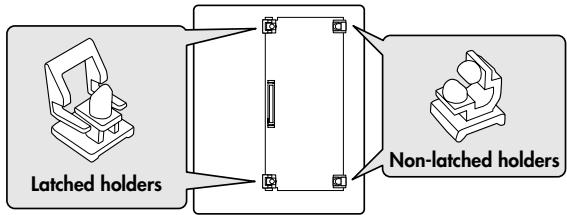
Installation in your product
- As described in your product's owner's manual, expose the slot in which the expansion board is to be installed.
- Orient the board with the slot of your product as shown in the illustration.
Slot of the product
flowchart
graph LR
    A["Latched holders"] --> B["Diagram of a rectangular structure"]
    C["Non-latched holders"] --> B
    style A fill:#f9f,stroke:#333
    style C fill:#f9f,stroke:#333
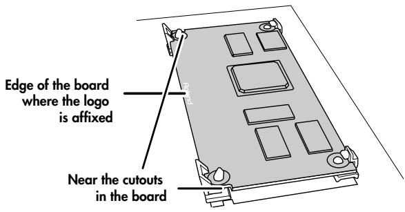
Board
(expansion board)
flowchart
graph TD
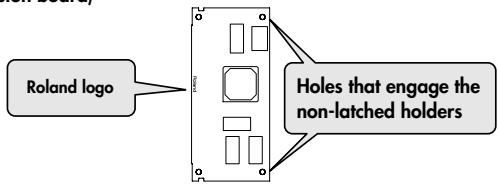
A["Roland logo"] --> B["Device"]
B --> C["Holes that engage the non-latched holders"]
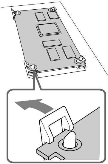
- Insert the board into the product's non-latched board holders until you hear a click.
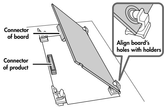
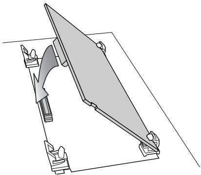
- Gently lower the board into place.
natural_image
Pure technical line drawing of a mechanical assembly without any text, numbers, or symbols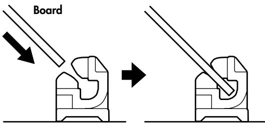
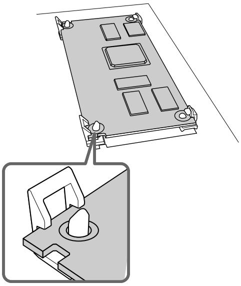
Non-latched holders
- From above, press down on the board at the three locations indicated in the illustration until the latched board holders lock into place.
- Verify that the latched board holders are locked.
natural_image
Technical line drawing of a mechanical component with mounting holes and a close-up view showing internal components (no text or symbols)- Return the expansion board installation slot to its original state.
Confirmation after installation
After you've finished installing the expansion board, you will need to perform the following procedure to confirm the installation. This installation procedure needs to be performed only the first time you power up your device after installing the expansion board.
- Power up your device as described in its owner's manual.
- If the expansion board was installed correctly, an installation confirmation screen will appear. Press [F8 (Execute)] button to begin installation.
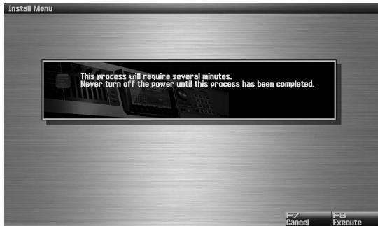
* The screen shown here is for when the board is installed in the Fantom-G.

If the installation confirmation screen does not appear the first time you power up after installing the expansion board, it is likely that the board was not installed correctly. Check once again to make sure that the board is correctly installed.

It may take five to ten minutes before installation is finished. Never turn off the power during this installation process.
- When you see the Power Off screen indicating that installation is finished, switch your device's power off, then on again as described in its owner's manual.
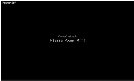
This completes the expansion board installation process.
To remove the board from the product
- As described in your product's owner's manual, expose the slot in which the expansion board was installed.
- Unlatch the latched board holders.
natural_image
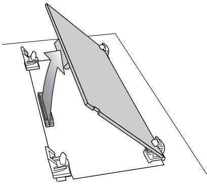
Diagram showing a device with mounting holes and a mechanical component, no text or symbols present- Verify that the two latched board holders are unlocked, then gently pull up the board and disconnect the connector.
natural_image
Technical line drawing of a mechanical assembly with no visible text or symbols- Disengage the board from the non-latched board holders, and remove the board.
for Canadian Safety Standard
natural_image
Technical line drawing of a mechanical assembly with no visible text or symbols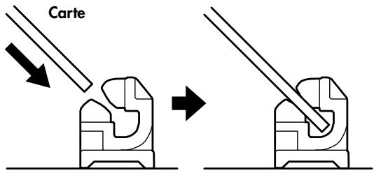
Supports non bloqués
natural_image
Technical line drawing of a mechanical component with mounting holes and a close-up view of its base (no text or symbols)natural_image
Diagram showing a device with mounting holes and a mechanical component, no text or symbols presentnatural_image
Technical line drawing of a mechanical assembly with no visible text or symbolsARX series SuperNATURAL expansion boards
The ARX series SuperNATURAL expansion boards represent a further evolution for Roland's line of expansion solutions, which began with the SR-JV80 series and SRX series—they are a completely new type of expansion board. SuperNATURAL technology delivers natural, richly expressive sounds and effects along with a dedicated graphic user interface, all adding up to a comprehensive application environment that allows an unprecedented degree of expressive playability and customization.
Roland SuperNATURAL Technology
SuperNATURAL
Proprietary Roland sound generation technology that realistically reproduces the tonal changes and performance techniques distinctive of an acoustic instrument, allowing you to perform music that is natural and richly expressive.
ARX-01 Drums
SuperNATURAL technology provides powerful drum customizing
The SuperNATURAL technology featured in the ARX-01 allows aggressive customization of the drum sounds. You can change the depth of the shell, the diameter of a cymbal, the position of the mic, or even the muffling (muting), giving you the same degree of customization that you have over an acoustic drum. Customizing the drum sound is easy, and does not require specialized knowledge. A graphical user interface allows you to edit intuitively while watching the screen. In contrast to the way in which you “choose a drum sound” on a conventional PCM synthesizer or sampler, this new technology lets you work more creatively to “make a drum kit” that’s just right for your song.
From acoustic drum sounds that cover the full range of musical styles to the sounds of vintage gear, such as the ever-popular TR-808/909, numerous presets are provided, giving you a powerful array of resources to create drum parts for your productions.
Effects that can be set independently for each tone, and powerful mixing functionality
Up to twenty-four different tones can be assigned to a single kit. A compressor and equalizer are provided for each tone. There's also a 24-channel mixer that lets you make detailed volume and pan settings
for each tone, in addition to a multi-effect and a reverb. Using just the ARX-01, you can construct drum parts that are at a level that's comparable to those used by recording studios.
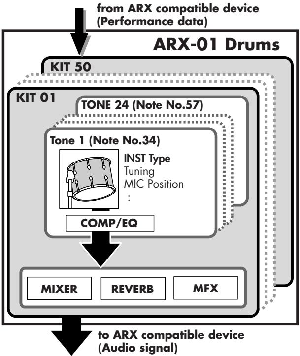
The structure of ARX-01 Drums
Basic structure
ARX series SuperNATURAL expansion boards can receive performance data and control data from devices that are compatible with the ARX series, and produce an appropriate stereo audio signal in response.
* ARX series boards support up to 16 parts, but the ARX-01 Drums board is designed to produce only one part.
Tones
A tone is the smallest unit of sound on the ARX-01 Drums board. A tone corresponds to one of the individual instruments (e.g., bass drum or cymbal) that makes up a drum set.
Each tone is provided with COMP (compressor) and EQ (equalizer).
You can also make settings such as Roll or Flam for each tone.
* You can't change the correspondence between note numbers and tones.
Kits
A group of twenty-four tones is called a Kit. A kit is provided with MFX (multi-effect) and reverb.
The twenty-four tones are assigned to note numbers 34 (B♭ 1) through 57 (A3).
The ARX-01 Drums board contains fifty kits.
If the board is installed in a Fantom-G, kit data is saved in the Fantom-G project.
flowchart
graph TD
    A["ARX-01 Drums"] --> B["KIT 50"]
    B --> C["KIT 01"]
    C --> D["TONE 24 (Note No.57)"]
    D --> E["Tone 1 (Note No.34)"]
    E --> F["COMP/EQ"]
    F --> G["MIXER"]
    F --> H["REVERB"]
    F --> I[" MFX "]
    J["to ARX compatible device (Audio signal)"] --> G
    J --> H
    J --> I
About this manual
- The screen images used in this manual are taken from a Fantom-G with the ARX-01 installed. The various procedures described also assume that you are using the ARX-01 installed in a Fantom-G.
- For details on how to move the cursor or edit a value, refer to the owner's manual for the device in which you've actually installed the ARX-01.
The basic screen
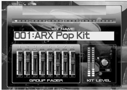
The basic screen shows the KIT NAME, twenty-four indicators that represent the Current Tone (p. 21), and the group faders.
When the basic screen is displayed, you can also assign a name to the kit and save it.
Selecting a kit
Move the cursor to KIT NAME and change the value to select a kit (001–050).
Group Fader
Eight faders are shown in the basic screen of the ARX-01. These are called the Group Faders.
You can divide the twenty-four tones among eight groups, and use these group faders to adjust the volume of the groups. To assign each tone to a group, use the Tone screen's Fader Group settings (p. 21).
Saving a kit (on the Fantom-G)
A kit you've created is temporary; it will be lost if you select a different kit. If you want to save the kit you've edited, proceed as follows.
- Press [WRITE] on the Fantom-G.
- Assign a name to the kit. For details on how to assign a name, refer to the Fantom-G owner's manual.
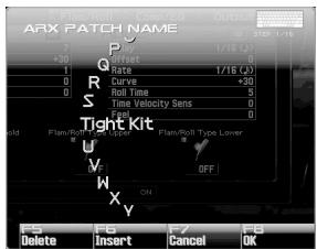
- When you've finished assigning the name, press [F8 (OK)] button.
- Select a kit number, and press [F8 (WRITE)] button.
- When the confirmation screen appears, press [F7 (OK)] button to save the kit.
Selecting a Tone (Tone screen)
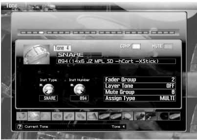
In the Tone screen you can select the tones that make up the kit.
* The Mute Switch in this screen is linked with the Mute Sw (p. 27) of the Tone/Output screen.
* The Comp Switch in this screen is linked with the Comp Sw (p. 26) of the Tone/ Comp/EQ screen.

When the Tone screen is displayed, you can switch the Current Tone by playing a key.
| Parameter | Value | Description |
| Current Tone | Tone 01 – Tone 24 | Indicates the tone number of the currently displayed tone. To select a tone, change this value. |
| Parameter | Value | Description |
| Inst Type | KICK, SNARE,TOM, HIHAT, RIDE,CYMBAL, OTHER,E.KICK, E.SNARE,E.TOM,E.HIHAT, E.RIDE,E.CYMBAL,E.OTHER | Selects the type of instrument. |
| Inst Number | (Depends on the "Inst Type") | Selects a variation of the instrument. |
| Fader Group | 1–8 | Assigns the tone to a fader group. |
| Layer Tone | OFF, Tone 01 – Tone 24 | If you want the current tone to sound simultaneously with another tone, specify the number of that tone. |
| Mute Group | 0(OFF), 1–24 | If there is a combination of tones that should not sound simultaneously,such as an open hi-hat sound and a closed hi-hat sound, set the Mute Group parameter of those tones to the same number.Mute Group is a function that prevents tones of the same setting from being heard together. If you don’t want to use this function, set this to 0. |
| Assign Type | MULTI, SINGLE | This specifies how the tone will sound when played repeatedly.MULTI: The same tone will be sounded on top of the already-sounding tone. If you repeatedly play a slow-decaying sound such as a cymbal,the new note will not silence the previous note.SINGLE: The currently sounding note will be silenced before the new note is played. |
Tone Settings
Customizing a tone (Tone/Customize screen)
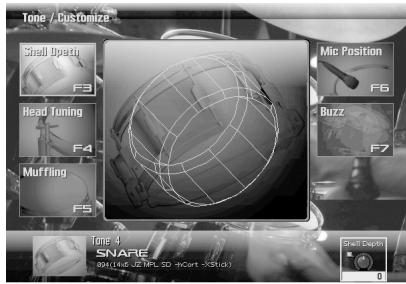
In the Tone/Customize screen you can adjust the sound in the same ways as on an acoustic drum; for example, by choosing the desired shell depth, and by installing muffling (muting).
The customizable parameters vary depending on the instrument type to which the tone belongs.
KICK, SNARE, TOM
| Parameter | Value |
| Shell Depth | -2→+2 |
| Head Tuning | -120→+120 |
| Muffling | 0→3 |
| Mic Position | -100→+100 |
| Buzz | 0→127 |
HIHAT, RIDE, CYMBAL
| Parameter | Value |
| Size | -120--+120 |
| Sustain | 0-100 |
OTHER
| Parameter | Value |
| Pitch | -120–120 |
| Sustain | 0–100 |
E.KICK
| Parameter | Value |
| Tune | -100→+100 |
| Attack Level | -100→+100 |
| Decay | -100→+100 |
| Cutoff | 0–127 |
| Resonance | 0–127 |
E.SNARE
| Parameter | Value |
| Tune | -100→+100 |
| Tone | -100→+100 |
| Attack Level | -100→+100 |
| Snpy Decay | -100→+100 |
| Cutoff | 0–127 |
| Resonance | 0–127 |
E.TOM, E.HIHAT, E.RIDE, E.OTHER
| Parameter | Value |
| Tune | -100→+100 |
| Decay | -100→+100 |
| Cutoff | 0–127 |
| Resonance | 0–127 |
E.CYMBAL
| Parameter | Value |
| Tune | -100→+100 |
| Tone | -100→+100 |
| Decay | -100→+100 |
| Cutoff | 0–127 |
| Resonance | 0–127 |
Flam/Roll settings (Tone/Flam/Roll screen)
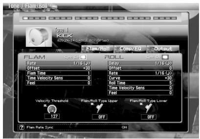
Here you can apply a fram or roll effect to each tone.
You can use note velocity to switch the flam or roll effect on/off.
| Parameter | Value | Description |
| Flam/Roll Velocity Threshold | 0–127 | Boundary between Upper and Lower |
| Flam/Roll Type Upper | OFF,FLAM,ROLL | Selects the way in which the tone will sound when the note velocity is above the Velocity Threshold setting. At OFF, the tone sounds in the normal way. |
| Flam/Roll Type Lower | OFF,FLAM,ROLL | Selects the way in which the tone will sound when the note velocity is below the Velocity Threshold setting. At OFF, the tone sounds in the normal way. |
Flam-related parameters
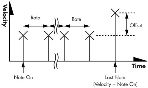
| Parameter | Value | Description |
| Rate | 1–100, note | Time interval between flam notes |
| Offset | -100–+100 | Difference in strength between note and flam note(s) |
| Flam Time | 1–16 | Number of flam notes |
| Time Velocity Sens | -100–+100 | Change in the number of flam notes in response to velocity. With a positive (+) setting, velocity will increase the number of flam notes; with a negative setting (-), velocity will decrease the number of flam notes. |
| Feel | 0–32 | Amount of random change in the strength of flam notes and their time interval |

For details on the "note" that can be selected for the Rate parameter, refer to "About Note" (p. 67)
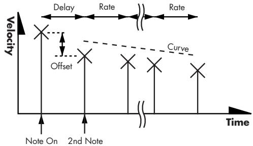
Roll-related parameters
line
| Time Point | Velocity | Annotation | | ---------- | -------- | ---------- | | 1 | High | X (Note On) | | 2 | Medium | X (Note On) | | 3 | Low | X (Note On) | | 4 | Medium | X (Note On) | | 5 | High | Curve | | 6 | Medium | X (Note On) | | 7 | Low | X (Note On) | | 8 | Medium | X (Note On) | | 9 | High | X (Note On) | | 10 | Medium | X (Note On) | | 11 | Low | X (Note On) | | 12 | Medium | X (Note On) | | 13 | High | X (Note On) | | 14 | Medium | X (Note On) | | 15 | Low | X (Note On) | | 16 | Medium | X (Note On) | | 17 | High | X (Note On) | | 18 | Medium | X (Note On) | | 19 | Low | X (Note On) | | 20 | Medium | X (Note On) | | 21 | High | X (Note On) | | 22 | Medium | X (Note On) | | 23 | Low | X (Note On) | | 24 | Medium | X (Note On) | | 25 | High | X (Note On) | | 26 | Medium | X (Note On) | | 27 | Low | X (Note On) | | 28 | Medium | X (Note On) | | 29 | High | X (Note On) | | 30 | Medium | X (Note On) | | 31 | Low | X (Note On) | | 32 | Medium | X (Note On) | | 33 | High | X (Note On) | | 34 | Medium | X (Note On) | | 35 | Low | X (Note On) | | 36 | Medium | X (Note On) | | 37 | High | X (Note On) | | 38 | Medium | X (Note On) | | 39 | Low | X (Note On) | | 40 | Medium | X (Note On) | | 41 | High | X (Note On) | | 42 | Medium | X (Note On) | | 43 | Low | X (Note On) | | 44 | Medium | X (Note On) | | 45 | High | X (Note On) | | 46 | Medium | X (Note On) | | 47 | Low | X (Note On) | | 48 | Medium | X (Note On) | | 49 | High | X (Note On) | | 50 | Medium | X (Note On) | | 51 | Low | X (Note On) | | 52 | Medium | X (Note On) | | 53 | High | X (Note On) | | 54 | Medium | X (Note On) | | 55 | Low | X (Note On) | | 56 | Medium | X (Note On) | | 57 | High | X (Note On) | | 58 | Medium | X (Note On) | | 59 | Low | X (Note On) | | 60 | Medium | X (Note On) | | 61 | High | X (Note On) | | 62 | Medium | X (Note On) | | 63 | Low | X (Note On) | | 64 | Medium | X (Note On) | | 65 | High | X (Note On) | | 66 | Medium | X (Note On) | | 67 | Low | X (Note On) | | 68 | Medium | X (Note On) | | 69 | High | X (Note On) | | 70 | Medium | X (Note On) | | 71 | Low | X (Note On) | | 72 | Medium | X (Note On) | | 73 | High | X (Note On) | | 74 | Medium | X (Note On) | | 75 | Low | X (Note On) | | 76 | Medium | X (Note On) | | 77 | High | X (Note On) | | 78 | Medium | X (Note On) | | 79 | Low | X (Note On) | | 80 | Medium | X (Note On) | | 81 | High | X (Note On) | | 82 | Medium | X (Note On) | | 83 | Low | X (Note On) | | 84 | Medium | X (Note On) | | 85 | High | X (Note On) | | 86 | Medium | X (Note On) | | 87 | Low | X (Note On) | | 88 | Medium | X (Note On) | | 89 | High | X (Note On) | | 90 | Medium | X (Note On) | | 91 | Low | X (Note On) | | 92 | Medium | X (Note On) | | 93 | High | X (Note On) | | 94 | Medium | X (Note On) | | 95 | Low | X (Note On) | | 96 | Medium | X (Note On) | | 97 | High | X (Note On) | | 98 | Medium | X (Note On) | | 99 | Low | X (Note On) | | Note | - | Note | Note on left: Offset Note on right: Offset Note on center: Note Note on right: Curve| Parameter | Value | Description |
| Rate | 1–100, note | Time interval between roll notes |
| Delay | 1–100 | Time interval until roll notes begin |
| Offset | -100–+100 | Difference in strength between note on and the first roll note |
| Curve | -100–+100 | Change in the strength of the roll notes. With a positive (+) setting, the roll notes will become stronger; with a negative (-) setting, the roll notes will become weaker. |
| Roll Time | 1–16 | Number of roll notes |
| Time Velocity Sens | -100–+100 | Change in the number of roll notes in response to velocity. With a positive (+) setting, velocity will increase the number of roll notes; with a negative setting (-), velocity will decrease the number of roll notes. |
| Feel | 0–32 | Amount of random change in the strength of roll notes and their time interval |
Volume change and tone adjustments (Tone/Comp/EQ screen)
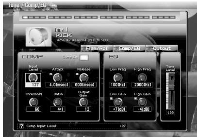
Here you can adjust the compressor and equalizer for each tone.
* The Tone Level in this screen is linked with the Tone Level parameter of the Tone/Output screen (p. 27).

Compressor
This reduces high levels and boosts low levels, making the overall volume more consistent.
Compressor-related parameters
| Parameter | Value | Description |
| Comp Sw | ON/OFF | Compressor on/off |
| Input Level | 0–127 | Volume level that is input to the compressor |
| Attack | 0.05–50.0 ms | Time from when the input exceeds the threshold until compression begins |
| Release | 0.05–200 ms | Time from when the input falls below the threshold until compression is turned off |
| Output Gain | 0–+24 dB | Level of the output sound |
| Threshold | 0–127 | Level above which compression is applied |
| Ratio | 1:1—∞:1 | Compression ratio |
EQ-related parameters
| Parameter | Value | Description |
| Low Freq | 50–400 Hz | Frequency of the low range |
| Low Gain | -15–+15 dB | Gain of the low frequency range |
| High Freq | 2000–16000 Hz | Frequency of the high range |
| High Gain | -15–+15 dB | Gain of the high frequency range |
Volume adjustment (Tone/Output screen)
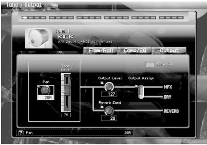
Here you can make settings related to the output of each tone.
Signal Flow
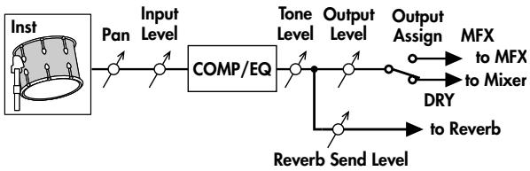
flowchart
graph LR
    A["Inst"] --> B["Pan"]
    B --> C["Input Level"]
    C --> D["COMP/EQ"]
    D --> E["Tone Level"]
    E --> F["Output Level"]
    F --> G["Output Assign"]
    G --> H["MFX to MFX to Mixer"]
    G --> I["DRY to Reverb"]
    E --> J["Reverb Send Level"]
| Parameter | Value | Description |
| Pan | L64 -0 -63R | Adjusts the pan of the tone. “L64” places the sound at far left, “0” at the center, and “63R” at the far right. |
| Tone Level | 0-127 | Specifies the volume of the tone. You’ll use this parameter mainly to adjust the volume balance relative to the other tones. |
| Output Level | 0-127 | Specifies the signal level of each tone. |
| Output Assign | DRY, MFX | Selects whether each tone will output its original sound or will use MFX.DRY: The original sound will be output without processing.MFX: The sound will be sent through the multi-effect before being output. |
| Reverb Send Level | 0-127 | Specifies the level of the signal sent from each tone to reverb. |
| Mute Sw | ON/OFF | Turns muting on/off for each tone. |
Adjusting the volume balance of the tones (Mixer screen)
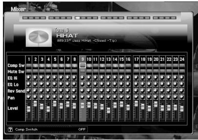
Here you can specify each tone's Comp Sw (p. 26), Mute Sw (p. 27), Reverb Send Level (p. 27), Pan (p. 27), Tone Level (p. 27), and EQ gain (p. 26).
Applying effects (Effects/Routing screen)
In the Effects/Routing screen you can make settings for multi-effect (MFX) and reverb.
| Parameter | Value | Description |
| MFX Type | 0(THRU), 1-47 | Selects the multi-effect type. For details on each type, refer to “Multi-Effects List” (p. 34) |
| MFX Output Level | 0-127 | Specifies the volume of the sound that has passed through the multi-effect. |
| MFX Reverb Send Level | 0-127 | Specifies the amount of reverb applied to the sound that has passed through the multi-effect. Choose “0” if you don’t want to apply reverb. |
| Reverb Type | 0(OFF), 1(REVERB), 2(SRV ROOM), 3(SRV HALL), 4(SRV PLATE) | Selects the type of reverb. For details on each type, refer to “Setting of Reverb (Effects/Reverb screen)” (p. 31) |
| Reverb Level | 0-127 | Specifies the volume of the sound that has passed through the reverb. |
Multi-effect settings (Effects/MFX screen)
In the Effects/MFX screen you can set the parameters of the multi-effect.
In this screen you can edit the parameters of the multi-effect you selected in "MFX Type" (p. 29). For details on the parameters that can be edited, refer to "Multi-Effects List" (p. 34).
| Parameter | Value | Description |
| MFX Type | 0(THRU), 1–47 | Selects the type of multi-effect. For details on each type, refer to “Multi-Effects List” (p. 34). |
| Control Assign 1–4 | (Depends on the “MFX Type”) | Multi-effect control lets you use MIDI messages to control the parameters of the multi-effect. For details, refer to “Multi-effect control (Effects/MFX Ctrl screen)” (p. 29). |

For details on Control Assign 1–4, refer to “Multi-effect control (Effects/MFX Ctrl screen)” (p. 29).
Multi-effect control (Effects/MFX Ctrl screen)
In order to control parameters such as the volume of the multi-effect or the delay time of a delay from an external MIDI device, you will normally need to transmit "MIDI system exclusive messages," which are a type of MIDI message that is specific to a particular device. However, system exclusive message settings are complex, and these messages will also increase the amount of data that needs to be transmitted.
Thus, this expansion board allows you to use MIDI messages such as control changes to control the most important multi-effect parameters. For example, you can use the pitch bend lever to vary the depth of distortion, or use your keyboard playing touch to change the delay time. The parameters that can be controlled in this way are pre-assigned for each multi-effect type. The parameters that are assigned for each multi-effect type are marked with a “#” in the list of “Multi-Effects Parameters” (p. 35).
This ability to use MIDI messages to vary the multi-effect parameters in real time is called "multi-effect control." The ARX-01 expansion board allows you to use four multi-effect controls simultaneously.
To use multi-effect control, you need to specify the MIDI message (Source 1–4) that will control the desired parameter (Control Assign 1–4) in the specified way (Sens 1–4).
MFX Control Source 1-4
| Value | Description |
| OFF | Multi-effect control will not be used. |
| CC01-31, 32(OFF), 33-95 | Control Change. |
| PITCH BEND | Pitch Bend. |
| AFTERTOUCH | Aftertouch. |
| AUDIO | Volume level that is input to the Multi-effect. |
MFX Control Sens 1-4
Specifies the depth to which multi-effect control will affect the parameter. Choose a positive (+) value if you want to modify the parameter from its current value toward the positive direction (higher value, toward the right, faster, etc.). Choose a negative (-) value if you want to modify the parameter from its current value toward the negative direction (lower value, toward the left, slower, etc.). With both positive (+) and negative (-) settings, the greater the number, the greater the change. Choose "0" if you don't want to modify the parameter.
Value: -63-+63
Setting of Reverb (Effects/Reverb screen)
In the Effects/Reverb screen you can set the parameters of the reverb.
| Parameter | Value | Description |
| Type | 0 (OFF),1 (REVERB),2 (SRV ROOM),3 (SRV HALL),4 (SRV PLATE) | Type of reverb |
| Type: 1 (REVERB) | ||
| Type | ROOM1,ROOM2,STAGE1,STAGE2,HALL1, HALL2,DELAY,PAN-DELAY | Type of reverb/delayROOM1: short reverb with high densityROOM2: short reverb with low densitySTAGE1: reverb with greater late reverberationSTAGE2: reverb with strong early reflectionsHALL1: very clear-sounding reverbHALL2: rich reverbDELAY: conventional delay effectPAN-DELAY: delay effect with echoes that pan left and right |
| Time | 0–127 | Time length of reverberation(Type: ROOM1.HALL2)Delay time(Type: DELAY, PAN-DELAY) |
| HF Damp | 200–8000 Hz,BYPASS | Adjusts the frequency above which the highfrequency content of the reverb sound will be cut, or “damped.” If you do not want to cut the high frequencies, set this parameter to BYPASS. |
| Parameter | Value | Description |
| Delay Feedback | 0–127 | Adjusts the amount of delay feedback when the Type setting is DELAY or PAN-DELAY. |
| Type:2(SRV ROOM)/3(SRV HALL)/4(SRV PLATE) | ||
| Pre Delay | 0.0–100.0 ms | Adjusts the delay time from the direct sound until the reverb sound is heard. |
| Time | 0–127 | Time length of reverberation |
| Size | 1–8 | Size of the simulated room or hall |
| High Cut | 160 Hz–12.5 kHz, BYPASS | Adjusts the frequency above which the high-frequency content of the reverb will be reduced. If you do not want to reduce the high frequencies, set this parameter to BYPASS. |
| Density | 0–127 | Density of reverb |
| Diffusion | 0–127 | Adjusts the change in the density of the reverb over time.The higher the value, the more the density increases with time. (The effect of this setting is most pronounced with long reverb times.) |
| LF Damp Freq | 50–4000 Hz | Adjusts the frequency below which the low-frequency content of the reverb sound will be reduced, or “damped.” |
| LF Damp Gain | -36–0 dB | Adjusts the amount of damping applied to the frequency range selected with LF Damp. With a setting of “0,” there will be no reduction of the reverb’s low-frequency content. |
| HF Damp Freq | 4000 Hz–12.5 kHz | Adjusts the frequency above which the highfrequency content of the reverb sound will be reduced, or “damped.” |
| HF Damp Gain | -36–0 dB | Adjusts the amount of damping applied to the frequency range selected with HF Damp. With a setting of “0,” there will be no reduction of the reverb’s high-frequency content. |
Choking/muting the drum sound (Ctrl screen)
Note number 58 (B♭3) is assigned the Choke/Mute function; by pressing this key, you can stop the sound of certain types of instrument that are currently sounding.
In the Ctrl screen you can specify the instrument that will be choked/muted.
* The manner of muting will depend on the velocity. A low velocity will mute the sound gradually, while a strong velocity will mute the sound quickly.
| Parameter | Value | Description |
| Mute Key Type | OFF, HHT, RID, CYM, RID-CYM, HHT-RID-CYM, ALL | Specify the type of instrument that will be choked/muted.OFF: The Choke/Mute function will not be used.HHT: The hi-hat sound will be muted.RID: The ride sound will be muted.CYM: The cymbal sound will be muted.RID-CYM: Ride and cymbal sound will be muted.HHT-RID-CYM: Hi-hat, ride and cymbal sound will be muted.ALL: All sound will be muted. |
Initializing a Kit/Tone or copying a Tone (Utility screen)
In the Utility screen you can initialize kits or tones, or copy the settings of a tone to a different tone.
Initializing a kit or tone
This operation lets you return the settings of the current kit or current tone to their default values.
Kit Init will initialize the settings of the current kit.
Tone Init will initialize the settings of the current tone.
- Select the kit or tone that you want to initialize.
- In the Utility screen, choose Kit Init or Tone Init.
- When the confirmation screen appears, press [F7 (OK)] button.
If you decide to cancel, press [F8 (EXIT)] button.
* If you've installed the ARX-01 in a Fantom-G6/G7/G8, executing a Factory Reset for the Fantom-G6/G7/G8 will reset the expansion boards to their factory-set condition.
Copying a tone
This operation lets you copy the settings of a tone to a different tone of the currently selected kit. Making good use of this operation will help you create kits efficiently.
- Select the tone that you want to copy.
- In the Utility screen, choose Tone Copy.
The Tone Copy screen will appear. - Choose the "Destination (copy-destination)" tone number.
- Press [F8 (Execute)] button.
A confirmation message will appear. - Press [F7 (OK)] button to execute the copy.
If you decide to cancel, press [F8 (EXIT)] button.
Multi-Effects Types
There are 47 types of multi-effect.
| FILTER (9 types) | ||
| 01 | STEREO EQ | p. 35 |
| 02 | SPECTRUM | p. 36 |
| 03 | ENHANCER | p. 36 |
| 04 | ISOLATOR | p. 37 |
| 05 | LOW BOOST | p. 37 |
| 06 | SUPER FILTER | p. 38 |
| 07 | STEP FILTER | p. 39 |
| 08 | AUTO WAH | p. 39 |
| 09 | HUMANIZER | p. 40 |
| MODULATION (7 types) | ||
| 10 | PHASER | p. 40 |
| 11 | STEREO PHASER | p. 41 |
| 12 | STEP PHASER | p. 41 |
| 13 | RING MODULATOR | p. 42 |
| 14 | TREMOLO | p. 43 |
| 15 | AUTO PAN | p. 43 |
| 16 | ROTARY | p. 44 |
| CHORUS (6 types) | ||
| 17 | HEXA-CHORUS | p. 45 |
| 18 | TREMOLO CHORUS | p. 45 |
| 19 | SPACE-D | p. 46 |
| 20 | STEREO CHORUS | p. 46 |
| 21 | STEREO FLANGER | p. 47 |
| 22 | STEP FLANGER | p. 48 |
| DYNAMICS (7 types) | ||
| 23 | OVERDRIVE | p. 48 |
| 24 | DISTORTION | p. 48 |
| 25 | GUITAR AMP SIMULATOR | p. 49 |
| 26 | STEREO COMPRESSOR | p. 50 |
| 27 | STEREO LIMITER | p. 51 |
| 28 | SLICER | p. 51 |
| 29 | GATE | p. 52 |
| LOFI (6 types) | ||
| 30 | LOFI NOISE | p. 53 |
| 31 | LOFI COMPRESS | p. 54 |
| 32 | LOFI RADIO | p. 54 |
| 33 | TELEPHONE | p. 55 |
| 34 | PHONOGRAPH | p. 55 |
| 35 | TAPE ECHO | p. 56 |
| PITCH (2 types) | ||
| 36 | FBK PITCH SHIFTER | p. 57 |
| 37 | 2Vo PITCH SHIFTER | p. 58 |
| REVERB (1 type) | ||
| 38 | GATED REVERB | p. 58 |
| DELAY (9 types) | ||
| 39 | STEREO DELAY | p. 59 |
| 40 | MODULATION DELAY | p. 60 |
| 41 | TRIPLE TAP DELAY | p. 61 |
| 42 | QUADRUPLE TAP DELAY | p. 61 |
| 43 | MULTI TAP DELAY | p. 62 |
| 44 | REVERSE DELAY | p. 63 |
| 45 | SHUFFLE DELAY | p. 63 |
| 46 | TIME CONTROL DELAY | p. 64 |
| 47 | TIME SKIP DELAY | p. 65 |
Multi-Effects Parameters

Each multi-effect has "Control Assign" parameters. These indicate the parameters that can be controlled via "Multi-effect control (Effects/MFX Ctrl screen)" (p. 29).

For details on the "note" that can be selected for some parameter, refer to "About Note" (p. 67)

In the parameter list below, an indication of “#1”-“#4” follows the name of parameters that are selected for Control Assign by default.
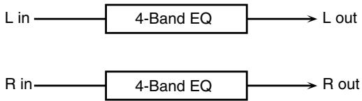
01: STEREO EQ (Stereo Equalizer)
This is a four-band stereo equalizer (low, mid x 2, high).
flowchart
graph LR
    A["L in"] --> B["4-Band EQ"] --> C["L out"]
    D["R in"] --> E["4-Band EQ"] --> F["R out"]
| Parameter | Value | Description |
| Low Freq | 200, 400 Hz | Frequency of the low range |
| Low Gain #1 | -15–+15 dB | Gain of the low frequency range |
| High Freq | 2000, 4000, 8000 Hz | Frequency of the high range |
| High Gain #4 | -15–+15 dB | Gain of the high frequency range |
| Mid1 Freq | 200–8000 Hz | Frequency of Middle Range 1 |
| Mid1 Q | 0.5, 1.0, 2.0, 4.0, 8.0 | Width of Middle Range 1Select a higher Q value to narrow Middle Range 1. |
| Mid1 Gain #2 | -15–+15 dB | Gain of Middle Range 1 |
| Mid2 Freq | 200–8000 Hz | Frequency of Middle Range 2 |
| Mid2 Q | 0.5, 1.0, 2.0, 4.0, 8.0 | Width of Middle Range 2Select a higher Q value to narrow Middle Range 2. |
| Mid2 Gain #3 | -15–+15 dB | Gain of Middle Range 2 |
| Level | 0–127 | Output level |
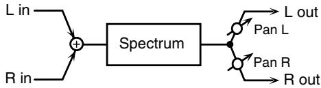
02: SPECTRUM
This is a type of filter that modifies the timbre by boosting or cutting the level of specific frequencies. It is similar to an equalizer, but has eight frequency points fixed at locations most useful for adding character to the sound.
flowchart
graph LR
    A["L in"] --> C["+"]
    B["R in"] --> C
    C --> D["Spectrum"]
    D --> E["Pan L"]
    D --> F["Pan R"]
    D --> G["R out"]
    E --> H["L out"]
    F --> I["R out"]
| Parameter | Value | Description |
| Q | 0.5, 1.0, 2.0, 4.0, 8.0 | Simultaneously adjusts the width of the adjusted ranges for all of the frequency bands. |
| Pan | L64–63R | Stereo location of the SPECTRUM output |
| Level | 0–127 | Output level |
| Band 1 (250 Hz) | -15– +15 dB | Gain of each frequency band* This can be set using the sliders of the part mixer. |
| Band 2 (500 Hz) #1 | ||
| Band 3 (1 kHz) #2 | ||
| Band 4 (1.25 kHz) | ||
| Band 5 (2 kHz) #3 | ||
| Band 6 (3.15 kHz) | ||
| Band 7 (4 kHz) #4 | ||
| Band 8 (8kHz) |
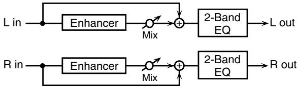
03: ENHANCER
Controls the overtone structure of the high frequencies, adding sparkle and brightness to the sound.
flowchart
graph LR
    A["L in"] --> B["Enhancer"]
    B --> C["Mix"]
    C --> D["+"]
    D --> E["2-Band EQ"]
    E --> F["L out"]
    G["R in"] --> H["Enhancer"]
    H --> I["Mix"]
    I --> J["+"]
    J --> K["2-Band EQ"]
    K --> L["R out"]
| Parameter | Value | Description |
| Sens #1 | 0–127 | Sensitivity of the enhancer |
| Mixl #2 | 0–127 | Level of the overtones generated by the enhancer |
| Low Gain | -15– +15 dB | Gain of the low frequency range of frequencies |
| High Gain | -15– +15 dB | Gain of the high frequency range of frequencies |
| Level | 0–127 | Output level |
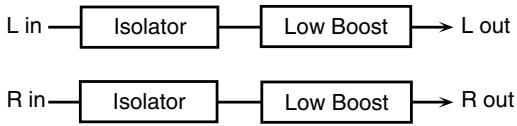
04: ISOLATOR
This is an equalizer that radically cuts the volume of selected frequencies, allowing you to create special effects cutting the volume in various ranges.
flowchart
graph LR
    A["L in"] --> B["Isolator"] --> C["Low Boost"] --> D["L out"]
    E["R in"] --> F["Isolator"] --> G["Low Boost"] --> H["R out"]
| Parameter | Value | Description |
| Boost/Cut High #3 | -60–+4 dB | These boost and cut each of the High, Middle, and Low frequency ranges.At -60 dB, the sound becomes inaudible. 0 dB is equivalent to the input level of the sound. |
| Boost/Cut Middle #2 | ||
| Boost/Cut Low #1 | ||
| AntiPhase Middle Sw | OFF, ON | Settings of the Anti-Phase function for the Middle frequency ranges.When turned on, a stereo copy of the sound is phase-inverted and added to the signal. |
| AntiPhase Middle Level | 0–127 | Adjusts the level settings for the Middle frequency ranges.Adjusting this level for certain frequencies allows you to lend emphasis to specific elements within a sound. (This is effective only for stereo source.) |
| Anti Phase Low Sw | OFF, ON | Settings of the Anti-Phase function for the Middle frequency rangesThe parameters are the same as for the Middle frequency ranges. |
| Anti Phase Low Level | 0–127 | |
| Low Boost Sw | OFF, ON | Turns Low Booster on/off.This emphasizes the bottom frequencies to create a heavy bass sound. |
| Low Boost Level | 0–127 | Increasing this value gives you a heavier low end.* Depending on the Isolator and filter settings, this effect may be hard to hear. |
| Level | 0–127 | Output level |
05: LOW BOOST
Boosts the volume of the lower range, creating powerful lows.
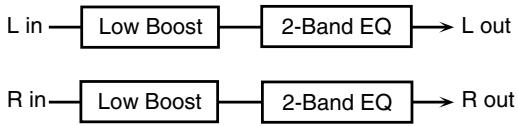
flowchart
graph LR
    A["L in"] --> B["Low Boost"]
    B --> C["2-Band EQ"]
    C --> D["L out"]
    E["R in"] --> F["Low Boost"]
    F --> G["2-Band EQ"]
    G --> H["R out"]
| Parameter | Value | Description |
| Boost Frequency #1 | 50–125 Hz | Center frequency at which the lower range will be boosted |
| Boost Gain #2 | 0–12 dB | Amount by which the lower range will be boosted |
| Boost Width #3 | WIDE, MID, NARROW | Width of the lower range that will be boosted |
| Low Gain | -15– +15 dB | Gain of the low frequency range |
| High Gain | -15– +15 dB | Gain of the high frequency range |
| Level | 0–127 | Output level |
06: SUPER FILTER
This is a filter with an extremely sharp slope. The cutoff frequency can be varied cyclically.
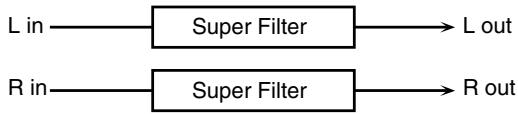
flowchart
graph LR
    A["L in"] --> B["Super Filter"] --> C["L out"]
    D["R in"] --> E["Super Filter"] --> F["R out"]
| Parameter | Value | Description |
| Filter Type #1 | LPF, BPF, HPF, NOTCH | Filter typeFrequency range that will pass through each filterLPF: frequencies below the cutoffBPF: frequencies in the region of the cutoffHPF: frequencies above the cutoffNOTCH: frequencies other than the region of the cutoff |
| Filter Slope | -12, -24,-36 dB | Amount of attenuation per octave-36 dB: extremely steep-24 dB: steep -12 dB: gentle |
| Filter Cutoff #2 | 0–127 | Cutoff frequency of the filterIncreasing this value will raise the cutoff frequency. |
| Filter Resonance #3 | 0–127 | Filter resonance levelIncreasing this value will emphasize the region near the cutoff frequency. |
| Filter Gain #4 | 0–+12 dB | Amount of boost for the filter output |
| Modulation Sw | OFF,ON | On/off switch for cyclic change |
| Modulation Wave | TRI, SQU,SIN, SAW1,SAW2 | How the cutoff frequency will be modulatedTRI: triangle waveSQR: square waveSIN: sine waveSAW1: sawtooth wave (upward)SAW2: sawtooth wave (downward) |
| Parameter | Value | Description |
| Rate | 0.05–10.0 Hz, note | Rate of modulation |
| Depth | 0–127 | Depth of modulation |
| Attack | 0–127 | Speed at which the cutoff frequency will changeThis is effective if Modulation Wave is SQR,SAW1, or SAW2. |
| Level | 0–127 | Output level |
07: STEP FILTER
This is a filter whose cutoff frequency can be modulated in steps. You can specify the pattern by which the cutoff frequency will change.
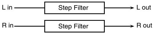
flowchart
graph LR
    A["L in"] --> B["Step Filter"] --> C["L out"]
    D["R in"] --> E["Step Filter"] --> F["R out"]
| Parameter | Value | Description |
| Rate #1 | 0.05–10.00 Hz, note | Rate of modulation |
| Attack | 0–127 | Speed at which the cutoff frequency changes between steps |
| Filter Type #2 | LPF, BPF, HPF, NOTCH | Filter typeFrequency range that will pass through each filterLPF: frequencies below the cutoffBPF: frequencies in the region of the cut-offHPF: frequencies above the cutoffNOTCH: frequencies other than the region of the cutoff |
| Filter Slope | -12, -24,-36 dB | Amount of attenuation per octave-12 dB: gentle-24 dB: steep-36 dB: extremely steep |
| Filter Resonance #3 | 0–127 | Filter resonance levelIncreasing this value will emphasize the region near the cutoff frequency. |
| Filter Gain #4 | 0– +12 dB | Amount of boost for the filter output |
| Level | 0– 127 | Output level |
| Step 01–16 | 0–127 | Cutoff frequency at each step |
08: AUTO WAH
A filter that turns on and off to create a cyclical change in timbre.
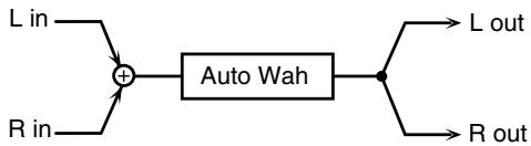
flowchart
graph LR
    A["L in"] --> C["+"]
    B["R in"] --> C
    C --> D["Auto Wah"]
    D --> E["L out"]
    D --> F["R out"]
| Parameter | Value | Description |
| Filter Type | LPF, BPF | Type of filterLPF: The wah effect is applied over a wide frequency range.BPF: The wah effect is applied over a narrow frequency range |
| Rate #3 | 0.05–10.00 Hz, note | Frequency of modulation |
| Depth #4 | 0–127 | Depth of modulation |
| Sens | 0–127 | Adjusts the sensitivity with which the filter is controlled. |
| Manual #1 | 0–127 | Adjusts the center frequency at which the effect is applied. |
| Peak #2 | 0–127 | Adjusts the amount of the wah effect that occurs in the range of the center frequency.Set a higher value for Q to narrow the range to be affected. |
| Level | 0–127 | Output level |
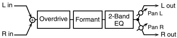
09: HUMANIZER
Adds a vowel character to the sound, making it similar to a human voice.
flowchart
graph LR
    A["L in"] --> C["+"]
    B["R in"] --> C
    C --> D["Overdrive"]
    D --> E["Formant"]
    E --> F["2-Band EQ"]
    F --> G["L out"]
    F --> H["Pan L"]
    F --> I["Pan R"]
    F --> J["R out"]
| Parameter | Value | Description |
| Drive Sw | OFF, ON | Turns Drive on/off. |
| Drive | 0–127 | Degree of distortionAlso changes the volume. |
| Vowel1 #1 | a, e, i, o, u | Selects the vowel. |
| Vowel2 #2 | a, e, i, o, u | |
| Rate #3 | 0.05–10.00 Hz, note | Frequency at which the two vowels switch |
| Depth | 0–127 | Effect depth |
| Input Sync Sw | OFF, ON | Determines whether the LFO for switching the vowels is reset by the input signal (ON) or not (OFF). |
| Input Sync Threshold | 0–127 | Volume level at which reset is applied |
| Manual #4 | 0–100 | Point at which Vowel 1/2 switch49 or less: Vowel 1 will have a longer duration.50: Vowel 1 and 2 will be of equal duration.51 or more: Vowel 2 will have a longer duration. |
| Low Gain | -15– +15 dB | Gain of the low frequency range |
| High Gain | -15– +15 dB | Gain of the high frequency range |
| Pan | L64–63R | Stereo location of the output |
| Level | 0–127 | Output level |
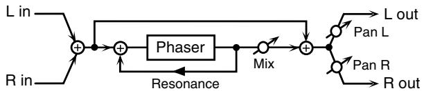
10: PHASER
Adds a phase-shifted sound to the original sound, producing a swirling modulation that creates spaciousness and depth.
flowchart
graph TD
    A["L in"] --> B["+"]
    C["R in"] --> B
    B --> D["+"]
    E["Phaser"] --> F["+"]
    G["Mix"] --> H["+"]
    I["R out"] --> H
    H --> J["L out"]
    H --> K["Pan L"]
    H --> L["Pan R"]
    H --> M["R out"]
    N["Resonance"] --> B
| Parameter | Value | Description |
| Manual #1 | 0–127 | Adjusts the basic frequency at which the sound will be modulated. |
| Rate #2 | 0.05–10.00 Hz, note | Frequency of modulation |
| Depth #3 | 0–127 | Depth of modulation |
| Resonance #4 | 0–127 | Amount of feedback |
| Mix | 0–127 | Level of the phase-shifted sound |
| Pan | L64–63R | Stereo location of the PHASER output |
| Level | 0–127 | Output Level |
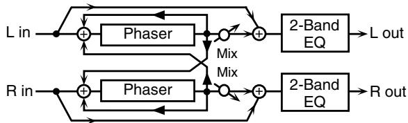
11:STEREO PHASER
This is a stereo phaser.
flowchart
graph TD
    A["L in"] --> B["+"]
    B --> C["Phaser"]
    C --> D["○"]
    D --> E["+"]
    E --> F["2-Band EQ"]
    F --> G["L out"]
    H["R in"] --> I["+"]
    I --> J["Phaser"]
    J --> K["○"]
    K --> L["+"]
    L --> M["2-Band EQ"]
    M --> N["R out"]
    B --> O["Mix Mix"]
    J --> P["Mix Mix"]
    O --> D
    P --> K
| Parameter | Value | Description |
| Mode | 4, 8 stage | Number of stages in the phaser |
| Polarity | INVERSE, SYNCHRO | Selects whether the left and right phase of the modulation are the same or opposite each other.INVERSE: The left and right phase are opposite. When using a mono source, this spreads the sound in stereo.SYNCHRO: The left and right phase are the same. Select this when working with a stereo source. |
| Rate #2 | 0.05–10.00Hz, note | Frequency of modulation |
| Depth #3 | 0–127 | Depth of modulation |
| Manual #1 | 0–127 | Adjusts the basic frequency from which the sound is modulated. |
| Resonance #4 | 0–127 | Amount of feedback |
| Cross Feedback | -98– +98 % | Adjusts the amount of the phaser sound that's fed back into the effect. Negative (-) settings invert the phase. |
| Mix | 0–127 | Level of the phase-shifted sound |
| Low Gain | -15– +15 dB | Gain of the low frequency range |
| High Gain | -15– +15 dB | Gain of the high frequency range |
| Level | 0–127 | Output level |
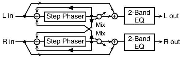
12:STEP PHASER
With the Step effects, you can also make stepped changes in the pitch of sounds to which the Phaser effect is applied.
flowchart
graph TD
    A["L in"] --> B["+"]
    B --> C["Step Phaser"]
    C --> D["+"]
    D --> E["2-Band EQ"]
    E --> F["L out"]
    G["R in"] --> H["+"]
    H --> I["Step Phaser"]
    I --> J["+"]
    J --> K["2-Band EQ"]
    K --> L["R out"]
    B --> M["Mix"]
    I --> N["Mix"]
    M --> D
    N --> J
| Parameter | Value | Description |
| Mode | 4, 8 stage | Number of stages in the phaser |
| Polarity | INVERSE, SYNCHRO | Selects whether the left and right phase of the modulation are the same or opposite each other.INVERSE:The left and right phase are opposite. When using a mono source, this spreads the sound in stereo.SYNCHRO:The left and right phase are the same. Select this when working with a stereo source. |
| Rate #2 | 0.05–10.00 Hz, note | Frequency of modulation |
| Depth | 0–127 | Depth of modulation |
| Manual #1 | 0–127 | Adjusts the basic frequency from which the sound is modulated. |
| Resonance #3 | 0–127 | Amount of feedback |
| Cross Feedback | -98– +98 % | Adjusts the amount of the phaser sound that's fed back into the effect. Negative (-) settings invert the phase. |
| Step Rate #4 | 0.1–20.0 Hz, note | Rate of pitch change |
| Mix | 0–127 | Level of the phase-shifted sound |
| Low Gain | -15– +15 dB | Gain of the low frequency range |
| High Gain | -15– +15 dB | Gain of the high frequency range |
| Level | 0–127 | Output level |
13: RING MODULATOR
This is an effect that applies amplitude modulation (AM) to the input signal, producing bell-like sounds. You can also change the modulation frequency in response to changes in the volume of the sound sent into the effect.

flowchart
graph LR
    A["L in"] --> B["Ring Mod"]
    B --> C["2-Band EQ"]
    C --> D["L out"]

flowchart
graph LR
    A["R in"] --> B["Ring Mod"]
    B --> C["2-Band EQ"]
    C --> D["R out"]
| Parameter | Value | Description |
| Frequency #1 | 0–127 | Adjusts the frequency at which modulation is applied. |
| Sens #2 | 0–127 | Adjusts the amount of frequency modulation applied. |
| Polarity | UP, DOWN | Determines whether the frequency modulation moves towards higher frequencies (UP) or lower frequencies (DOWN). |
| Low Gain | -15– +15 dB | Gain of the low frequency range |
| High Gain | -15– +15 dB | Gain of the high frequency range |
| Balance #3 | D100:0W–D0:100W | Volume balance between the direct sound (D) and the effect sound (W) |
| Level | 0–127 | Output level |
14: TREMOLO
Cyclically modulates the volume to add tremolo to the sound.
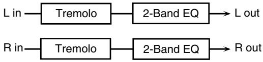
flowchart
graph LR
    A["L in"] --> B["Tremolo"]
    B --> C["2-Band EQ"] --> D["L out"]
    E["R in"] --> F["Tremolo"]
    F --> G["2-Band EQ"] --> H["R out"]
| Parameter | Value | Description |
| Modulation Wave #1 | TRI, SQR, SIN, SAW1, SAW2 | Modulation Wave TRI: triangle waveSQR: square waveSIN: sine waveSAW1: sawtooth wave (upward)SAW2: sawtooth wave (downward) |
| Rate #2 | 0.05–10.00 Hz, note | Frequency of the change |
| Depth #3 | 0–127 | Depth to which the effect is applied |
| Low Gain | -15– +15 dB | Gain of the low frequency range |
| High Gain | -15– +15 dB | Gain of the high frequency range |
| Level | 0–127 | Output level |
15: AUTO PAN
Cyclically modulates the stereo location of the sound.
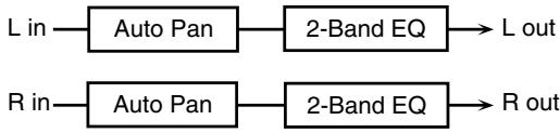
flowchart
graph LR
    A["L in"] --> B["Auto Pan"]
    B --> C["2-Band EQ"] --> D["L out"]
    E["R in"] --> F["Auto Pan"]
    F --> G["2-Band EQ"] --> H["R out"]
| Parameter | Value | Description |
| Modulation Wave #1 | TRI, SQR, SIN, SAW1, SAW2 | Modulation Wave TRI: triangle waveSQR: square waveSIN: sine waveSAW1: sawtooth wave (upward)SAW2: sawtooth wave (downward) |
| Rate #2 | 0.05–10.00 Hz, note | Frequency of the change |
| Depth #3 | 0–127 | Depth to which the effect is applied |
| Low Gain | -15–+15 dB | Gain of the low frequency range |
| High Gain | -15–+15 dB | Gain of the high frequency range |
| Level | 0–127 | Output level |
16: ROTARY
The Rotary effect simulates the sound of the rotary speakers often used with the classic electric organs. Since the movement of the high-range and low-range rotors can be set independently, the unique characteristics of these speakers can be simulated quite accurately. This effect is most suitable for electric organ Patches.
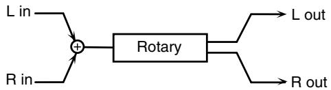
flowchart
graph LR
    A["L in"] --> C["+"]
    B["R in"] --> C
    C --> D["Rotary"]
    E["L out"] --> D
    F["R out"] --> D
| Parameter | Value | Description |
| Tweeter Slow Rate #1 | 0.05–10.00 Hz | Slow speed (SLOW) of the high-frequency rotor |
| Woofer Slow Rate #2 | 0.05–10.00 Hz | Slow speed (SLOW) of the low-frequency rotor |
| Tweeter Fast Rate #3 | 0.05–10.00 Hz | Fast speed (FAST) of the high-frequency rotor |
| Woofer Fast Rate #4 | 0.05–10.00 Hz | Fast speed (FAST) of the low-frequency rotor |
| Speed | SLOW, FAST | Simultaneously switches the rotational speed of the low frequency rotor and high frequency rotor.SLOW: Slows down the speed to the Slow Rate.FAST: Speeds up the speed to the Fast Rate. |
| Tweeter Acceleration | 0–15 | Adjusts the time it takes the high frequency rotor to reach the newly selected speed when switching between fast and slow speeds. |
| Woofer Acceleration | 0–15 | Adjusts the time it takes the low frequency rotor to reach the newly selected speed when switching between fast and slow speeds. |
| Tweeter Level | 0–127 | Volume of the high frequency rotor |
| Parameter | Value | Description |
| Woofer Level | 0–127 | Volume of the low frequency rotor |
| Separation | 0–127 | Stereo width of the sound |
| Level #2 | 0–127 | Output level |
17: HEXA-CHORUS
Uses a six-phase chorus (six layers of chorused sound) to give richness and spaciousness to the sound.
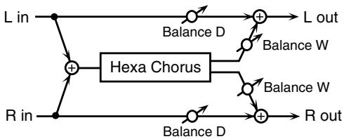
flowchart
graph TD
    L_in --> A["+"]
    R_in --> A
    A --> B["Hexa Chorus"]
    B --> C["+"]
    D["Balance D"] --> E["+"]
    F["Balance W"] --> G["+"]
    H["Balance W"] --> I["+"]
    J["Balance D"] --> K["+"]
    L_out --> E
    L_out --> G
    L_out --> I
    R_out --> K
| Parameter | Value | Description |
| Pre Delay | 0.0–100.0 ms | Adjusts the time until chorusing is heard. |
| Rate #1 | 0.05–10.00 Hz, note | Frequency of modulation |
| Depth #2 | 0–127 | Depth of modulation |
| Pre Delay Deviation | 0–20 | Adjusts the differences in Pre Delay between each chorus layer. |
| Depth Deviation | -20–+20 | Adjusts the difference in modulation depth between each chorus layer. |
| Pan Deviation | 0–20 | Adjusts the difference in stereo location between each chorus layer.0: All chorus layers are in the center.20: The chorus layers are spaced at 60-degree intervals relative to the center. |
| Balance #3 | D100:0W–D0:100W | Volume balance between the direct sound (D) and the chorus sound (W) |
| Level | 0–127 | Output level |
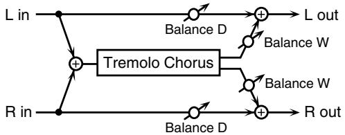
18: TREMOLO CHORUS
This is a chorus effect with added Tremolo (cyclic modulation of volume).
flowchart
graph TD
    L_in --> A["+"] --> B["Balance D"] --> C["+"] --> L_out
    R_in --> A
    A --> D["Tremolo Chorus"]
    D --> E["Balance W"] --> F["+"] --> G["R out"]
    D --> H["Balance W"] --> I["+"] --> G
    D --> J["Balance W"] --> K["+"] --> G
| Parameter | Value | Description |
| Pre Delay | 0.0–100.0 ms | Adjusts the time until the chorus sound is heard. |
| Chorus Rate | 0.05–10.00 Hz, note | Modulation frequency of the chorus effect |
| Chorus Depth | 0–127 | Modulation depth of the chorus effect |
| Tremolo Rate #1 | 0.05–10.00 Hz, note | Modulation frequency of the tremolo effect |
| Tremolo Separation | 0–127 | Spread of the tremolo effect |
| Tremolo Phase | 0–180 deg | Phase of the tremolo effect |
| Balance #2 | D100:0W–D0:100W | Volume balance between the direct sound (D) and the tremolo chorus sound (W) |
| Level | 0–127 | Output level |
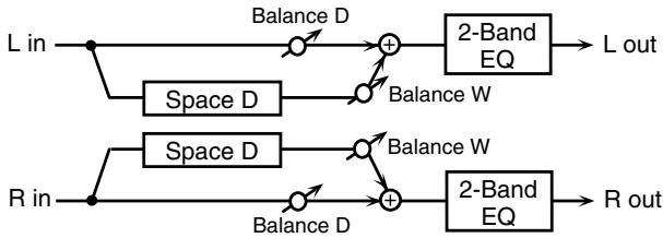
19: SPACE-D
This is a multiple chorus that applies two-phase modulation in stereo. It creates no audible modulation, yet produces a transparent chorus effect.
flowchart
graph LR
    L_in --> Space_D1["Space D"]
    Space_D1 --> Balance_D1["Balance D"]
    Balance_D1 --> Add1["+"]
    Add1 --> 2_BandEQ1["2-Band EQ"]
    2_BandEQ1 --> L_out["L out"]
    R_in --> Space_D2["Space D"]
    Space_D2 --> Balance_D2["Balance D"]
    Balance_D2 --> Add2["+"]
    Add2 --> 2_BandEQ2["2-Band EQ"]
    2_BandEQ2 --> R_out["R out"]
| Parameter | Value | Description |
| Pre Delay | 0.0–100.0 ms | Adjusts the time until the chorus sound is heard. |
| Rate #1 | 0.05–10.00 Hz, note | Frequency of modulation |
| Depth #2 | 0–127 | Depth of modulation |
| Phase | 0–180 deg | Spatial spread of the sound |
| Low Gain | -15– +15 dB | Gain of the low frequency range |
| High Gain | -15– +15 dB | Gain of the high frequency range |
| Balance #3 | D100:0W–D0:100W | Volume balance between the direct sound (D) and the chorus sound (W) |
| Level | 0–127 | Output level |
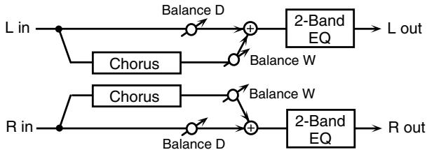
20: STEREO CHORUS
This is a stereo chorus. A filter is provided so that you can adjust the timbre of the chorused sound.
flowchart
graph LR
    A["L in"] --> B["Chorus"]
    B --> C["Balance D"]
    C --> D["+"]
    D --> E["2-Band EQ"]
    E --> F["L out"]
    G["R in"] --> H["Chorus"]
    H --> I["Balance D"]
    I --> J["+"]
    J --> K["2-Band EQ"]
    K --> L["R out"]
    D --> M["Balance W"]
    M --> N["+"]
    N --> O["2-Band EQ"]
    O --> P["Balance W"]
| Parameter | Value | Description |
| Filter Type | OFF, LPF, HPF | Type of filterOFF: no filter is usedLPF: cuts the frequency range above the Cutoff FreqHPF: cuts the frequency range below the Cutoff Freq |
| Cutoff Freq | 200–8000 Hz | Basic frequency of the filter |
| Pre Delay | 0.0–100.0 ms | Adjusts the time until the chorus sound is heard. |
| Rate #1 | 0.05–10.00 Hz, note | Frequency of modulation |
| Depth #2 | 0–127 | Depth of modulation |
| Phase | 0–180 deg | Spatial spread of the sound |
| Low Gain | -15–+15 dB | Gain of the low frequency range |
| High Gain | -15–+15 dB | Gain of the high frequency range |
| Balance #3 | D100:0W–D0:100W | Volume balance between the direct sound (D) and the chorus sound (W) |
| Level | 0–127 | Output level |
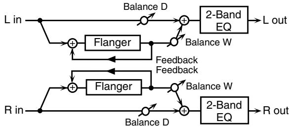
21: STEREO FLANGER
This is a stereo flanger. It produces a metallic resonance that rises and falls somewhat like a jet airplane taking off or landing. A filter is provided so that you can adjust the timbre of the flanged sound.
flowchart
graph TD
    A["L in"] --> B["+"]
    B --> C["Flanger"]
    C --> D["+"]
    D --> E["2-Band EQ"]
    E --> F["L out"]
    G["R in"] --> H["+"]
    H --> I["Flanger"]
    I --> J["+"]
    J --> K["2-Band EQ"]
    K --> L["R out"]
    M["Balance D"] --> D
    N["Balance W"] --> D
    O["Feedback Feedback"] --> H
    P["Balance W"] --> J
    Q["Balance D"] --> H
| Parameter | Value | Description |
| Filter Type | OFF, LPF, HPF | Type of filterOFF: no filter is usedLPF: cuts the frequency range above the Cutoff FreqHPF: cuts the frequency range below the Cutoff Freq |
| Cutoff Freq | 200–8000 Hz | Basic frequency of the filter |
| Pre Delay | 0.0–100.0 ms | Adjusts the time until the flanger sound is heard. |
| Rate #1 | 0.05-10.00 Hz, note | Frequency of modulation |
| Depth #2 | 0–127 | Depth of modulation |
| Phase | 0–180 deg | Spatial spread of the sound |
| Feedback #3 | -98– +98 % | Adjusts the amount of the flanger sound that's fed back into the effect. Negative (-) settings invert the phase. |
| Parameter | Value | Description |
| Low Gain | -15– +15 dB | Gain of the low frequency range |
| High Gain | -15– +15 dB | Gain of the high frequency range |
| Balance #4 | D100:0W–D0:100W | Volume balance between the direct sound (D) and the flanger sound (W) |
| Level | 0–127 | Output level |
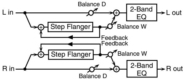
22: STEP FLANGER
This is a flanger in which the flanger pitch changes in steps. The speed at which the pitch changes can also be specified in terms of a note value based on a specified tempo.
flowchart
graph TD
    L_in --> A["+"]
    A --> B["Step Flanger"]
    B --> C["+"]
    C --> D["Balance D"]
    D --> E["2-Band EQ"]
    E --> F["L out"]
    R_in --> G["+"]
    G --> H["Step Flanger"]
    H --> I["+"]
    I --> J["Balance W"]
    J --> K["Feedback Feedback"]
    K --> B
    E --> L["2-Band EQ"]
    L --> M["R out"]
| Parameter | Value | Description |
| Pre Delay | 0.0–100.0 ms | Adjusts the time until the flanger sound is heard. |
| Rate #1 | 0.05–10.00 Hz, note | Frequency of modulation |
| Depth | 0–127 | Depth of modulation |
| Feedback #2 | -98– +98 % | Adjusts the amount of the flanger sound that's fed back into the effect. Negative (-) settings invert the phase. |
| Step Rate #3 | 0.10–20.00 Hz, note | Rate (period) of pitch change |
| Phase | 0–180 deg | Spatial spread of the sound |
| Low Gain | -15– +15 dB | Gain of the low frequency range |
| High Gain | -15– +15 dB | Gain of the high frequency range |
| Balance #4 | D100:0W–D0:100W | Volume balance between the direct sound (D) and the flanger sound (W) |
| Level | 0–127 | Output level |
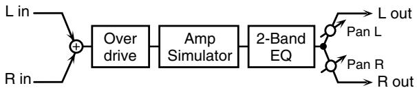
23: OVERDRIVE
Creates a soft distortion similar to that produced by vacuum tube amplifiers.
flowchart
graph LR
    A["L in"] --> C["+"]
    B["R in"] --> C
    C --> D["Over drive"]
    D --> E["Amp Simulator"]
    E --> F["2-Band EQ"]
    F --> G["L out"]
    F --> H["R out"]
    I["Pan L"] --> F
    J["Pan R"] --> F
| Parameter | Value | Description |
| Drive #1 | 0–127 | Amount of distortionAlso changes the volume. |
| Tone #2 | 0–127 | Sound Quality |
| Pan #4 | L64–63R | Stereo location of the OVERDRIVE output |
| Amp Sw | OFF, ON | Amp simulator on/off |
| Amp Type #3 | SMALL,BUILT-IN,2-STACK,3-STACK | Type of guitar ampSMALL:small ampBUILT-IN:single-unit type amp2-STACK:large double-stack amp3-STACK:large triple-stack amp |
| Low Gain | -15– +15 dB | Gain of the low frequency range |
| High Gain | -15– +15 dB | Gain of the high frequency range |
| Level | 0–127 | Output level |
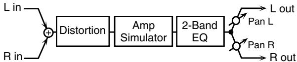
24: DISTORTION
Produces a more intense distortion than Overdrive. The parameters are the same as for "23: OVERDRIVE."
flowchart
graph LR
    A["L in"] --> B["+"]
    C["R in"] --> B
    B --> D["Distortion"]
    D --> E["Amp Simulator"]
    E --> F["2-Band EQ"]
    F --> G["L out"]
    F --> H["R out"]
    I["Pan L"] --> F
    J["Pan R"] --> F
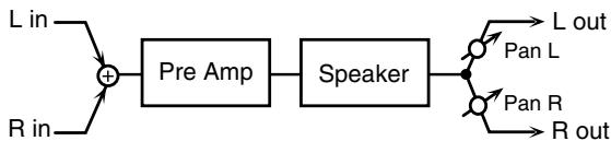
25: GUITAR AMP SIM (Guitar Amp Simulator)
This is an effect that simulates the sound of a guitar amplifier.
flowchart
graph LR
    A["L in"] --> C["+"]
    B["R in"] --> C
    C --> D["Pre Amp"]
    D --> E["Speaker"]
    E --> F["L out"]
    E --> G["Pan L"]
    E --> H["Pan R"]
    E --> I["R out"]
| Parameter | Value | Description |
| Pre Amp Sw | OFF, ON | Turns the amp switch on/off. |
| Pre Amp Type #1 | JC-120,Clean Twin,Match Drive,BG Lead,MS1959I,MS1959II,MS1959I+II, SLDNLead, Metal 5150,Metal Lead,OD-1, OD-2 TURBO,Distortion, Fuzz | Type of guitar amp |
| Pre Amp Volume #2 | 0–127 | Volume and amount of distortion of the amp |
| Pre Amp Master #3 | 0–127 | Volume of the entire pre-amp |
| Pre Amp Gain | Low, Mid, High | Amount of pre-amp distortion |
| Pre Amp Bass | 0–127 | Tone of the bass/mid/treble frequency range* Middle cannot be set if “Match Drive” is selected as the Pre Amp Type. |
| Pre Amp Middle | ||
| Pre Amp Treble | ||
| Pre Amp Presence | 0–127(MATCH DRIVE:-127 - 0) | Tone for the ultra-high frequency range |
| Parameter | Value | Description |
| Pre Amp Bright | OFF, ON | Turning this “On” produces a sharper and brighter sound.* This parameter applies to the “JC-120,” “Clean Twin,” and “BG Lead” Pre Amp Types. |
| Speaker Sw | OFF, ON | Determines whether the signal passes through the speaker (ON), or not (OFF). |
| Speaker Type #4 | (See the table below.) | Type of speaker |
| Mic Setting | 1, 2, 3 | Adjusts the location of the mic that’s capturing the sound of the speaker.This can be adjusted in three steps, from 1 to 3, with the mic becoming more distant as the value increases. |
| Mic Level | 0–127 | Volume of the microphone |
| Direct Level | 0–127 | Volume of the direct sound |
| Pan | L64–63R | Stereo location of the output |
| Level | 0–127 | Output level |
Specifications for each Speaker Type
The speaker column indicates the diameter of each speaker unit (in inches) and the number of units.
| Type | Cabinet | Speaker | Microphone |
| Small1 | small open-back enclosure | 10 | dynamic |
| Small2 | small open-back enclosure | 10 | dynamic |
| Middle | open back enclosure | 12 × 1 | dynamic |
| JC-120 | open back enclosure | 12 × 2 | dynamic |
| Built In 1 | open back enclosure | 12 × 2 | dynamic |
| Built In 2 | open back enclosure | 12 × 2 | condenser |
| Built In 3 | open back enclosure | 12 × 2 | condenser |
| Built In 4 | open back enclosure | 12 × 2 | condenser |
| Built In 5 | open back enclosure | 12 × 2 | condenser |
| BG Stack 1 | sealed enclosure | 12 × 2 | condenser |
| BG Stack 2 | large sealed enclosure | 12 × 2 | condenser |
| MS Stack1 | large sealed enclosure | 12 × 4 | condenser |
| MS Stack 2 | large sealed enclosure | 12 × 4 | condenser |
| Metal Stack | large double stack | 12 × 4 | condenser |
| 2 Stack | large double stack | 12 × 4 | condenser |
| 3 Stack | large triple stack | 12 × 4 | condenser |
26: COMPRESSOR
Flattens out high levels and boosts low levels, smoothing out fluctuations in volume.

flowchart
graph LR
    A["L in"] --> B["Compressor"]
    B --> C["2-Band EQ"]
    C --> D["L out"]

flowchart
graph LR
    A["R in"] --> B["Compressor"]
    B --> C["2-Band EQ"]
    C --> D["R out"]
| Parameter | Value | Description |
| Attack #1 | 0–127 | Sets the speed at which compression starts |
| Threshold #2 | 0–127 | Adjusts the volume at which compression begins |
| Post Gain #3 | 0–18 dB | Adjusts the output gain. |
| Low Gain | -15– +15 dB | Gain of the low frequency range |
| High Gain | -15– +15 dB | Gain of the high frequency range |
| Level | 0–127 | Output level |
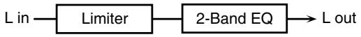
27: LIMITER
Compresses signals that exceed a specified volume level, preventing distortion from occurring.
flowchart
graph LR
    A["L in"] --> B["Limiter"]
    B --> C["2-Band EQ"]
    C --> D["L out"]

flowchart
graph LR
    A["R in"] --> B["Limiter"]
    B --> C["2-Band EQ"]
    C --> D["R out"]
| Parameter | Value | Description |
| Release #1 | 0–127 | Adjusts the time after the signal volume falls below the Threshold Level until compression is no longer applied. |
| Threshold #2 | 0–127 | Adjusts the volume at which compression begins |
| Ratio #3 | 1.5:1, 2:1, 4:1, 100:1 | Compression ratio |
| Post Gain #4 | 0–18 dB | Adjusts the output gain. |
| Low Gain | -15– +15 dB | Gain of the low frequency range |
| High Gain | -15– +15 dB | Gain of the high frequency range |
| Level | 0–127 | Output level |
28: SLICER
By applying successive cuts to the sound, this effect turns a conventional sound into a sound that appears to be played as a backing phrase. This is especially effective when applied to sustain-type sounds.

flowchart
graph LR
    A["L in"] --> B["Slicer"]
    B --> C["L out"]

flowchart
graph LR
    A["R in"] --> B["Slicer"]
    B --> C["R out"]
| Parameter | Value | Description |
| Rate #1 | 0.05–10.00 Hz, note | Rate at which the 16-step sequence will cycle |
| Attack #2 | 0–127 | Speed at which the level changes between steps |
| Input Sync Sw | OFF, ON | Specifies whether an input note will cause the sequence to resume from the first step of the sequence (ON) or not (OFF) |
| Input Sync Threshold | 0–127 | Volume at which an input note will be detected |
| Mode | LEGATO, SLASH | Sets the manner in which the volume changes as one step progresses to the next.LEGATO: The change in volume from one step's level to the next remains unaltered. If the level of a following step is the same as the one preceding it, there is no change in volume.SLASH: The level is momentarily set to 0 before progressing to the level of the next step. This change in volume occurs even if the level of the following step is the same as the preceding step. |
| Shuffle | 0–127 | Timing of volume changes in levels for even-numbered steps (step 2, step 4, step 6...).The higher the value, the later the beat progresses. |
| Level | 0–127 | Output level |
| Step 01–16 | 0–127 | Level at each step |
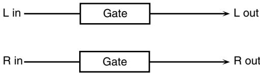
29: GATE
Cuts the reverb's delay according to the volume of the sound sent into the effect. Use this when you want to create an artificial-sounding decrease in the reverb's decay.
flowchart
graph LR
    A["L in"] --> B["Gate"] --> C["L out"]
    D["R in"] --> E["Gate"] --> F["R out"]
| Parameter | Value | Description |
| Threshold #1 | 0–127 | Volume level at which the gate begins to close |
| Mode | GATE, DUCK | Type of gateGATE: The gate will close when the volume of the original sound decreases, cutting the original sound.DUCK (Ducking): The gate will close when the volume of the original sound increases, cutting the original sound. |
| Balance | D100:0W–D0:100W | Volume balance between the direct sound (D) and the effect sound (W) |
| Attack Time #2 | 0–127 | Adjusts the time it takes for the gate to fully open after being triggered. |
| Hold Time #3 | 0–127 | Adjusts the time it takes for the gate to start closing after the source sound falls beneath the Threshold. |
| Release Time #4 | 0–127 | Adjusts the time it takes the gate to fully close after the hold time. |
| Level | 0–127 | Output level |
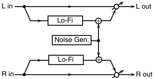
30: LOFI NOISE (Lo-Fi Noise)
In addition to a lo-fi effect, this adds various types of noise such as white noise and disc noise.
flowchart
graph TD
    A["L in"] --> B["Lo-Fi"]
    B --> C["+"]
    D["R in"] --> E["Lo-Fi"]
    E --> F["+"]
    C --> G["L out"]
    F --> H["R out"]
    I["Noise Gen."] --> C
    I --> F
| Parameter | Value | Description |
| LoFi Type #1 | 1–9 | Degrades the sound quality. The sound quality grows poorer as this value is increased. |
| Post Filter Type | OFF, LPF, HPF | Type of filterOFF: no filter is usedLPF: cuts the frequency range above the CutoffHPF: cuts the frequency range below the Cutoff |
| Post Filter Cutoff | 200–8000 Hz | Center frequency of the filter |
| W/P Noise Type | WHITE, PINK | Switch between white noise and pink noise. |
| W/P Noise LPF | 200–8000 Hz, BYPASS | Center frequency of the low pass filter applied to the white/pink noise (BYPASS: no cut) |
| W/P Noise Level #2 | 0–127 | Volume of the white/pink noise |
| Parameter | Value | Description |
| Disc Noise Type | LP, EP, SP, RND | Type of record noiseThe frequency at which the noise is heard depends on the selected type. |
| Disc Noise LPF | 200–8000 Hz, BYPASS | Adjusts the cutoff frequency of the low pass filter applied to the record noise. If you don't want to filter out any high frequencies, set this parameter to BYPASS. |
| Disc Noise Level #3 | 0–127 | Volume of the record noise |
| Hum Noise Type | 50Hz, 60Hz | Frequency of the hum noise |
| Hum Noise LPF | 200–8000 Hz, BYPASS | Center frequency of the low pass filter applied to the hum noise (BYPASS: no cut) |
| Hum Noise Level #4 | 0–127 | Volume of the hum noise |
| Balance | D100:0W–D0:100W | Volume balance between the direct sound (D) and the effect sound (W) |
| Level | 0–127 | Output level |
31: LOFI COMPRESS (Lo-Fi Compress)
This is an effect that intentionally degrades the sound quality for creative purposes.
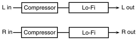
flowchart
graph LR
    A["L in"] --> B["Compressor"]
    B --> C["Lo-Fi"]
    C --> D["L out"]
    E["R in"] --> F["Compressor"]
    F --> G["Lo-Fi"]
    G --> H["R out"]
| Parameter | Value | Description |
| Pre Filter Type #2 | 1-6 | Selects the type of filter applied to the sound before it passes through the Lo-Fi effect. |
| LoFi Type #1 | 1-9 | Degrades the sound quality. The sound quality grows poorer as this value is increased. |
| Post Filter Type | OFF, LPF, HPF | Type of filterOFF: no filter is usedLPF: cuts the frequency range above the CutoffHPF: cuts the frequency range below the Cutoff |
| Post Filter Cutoff | 200-8000 Hz | Basic frequency of the Post Filter |
| Balance #3 | D100:0W-D0:100W | Volume balance between the direct sound (D) and the effect sound (W) |
| Level | 0-127 | Output level |
32: LOFI RADIO (Lo-Fi Radio)
In addition to a Lo-Fi effect, this effect also generates various types of noise, such as radio noise or disk noise.
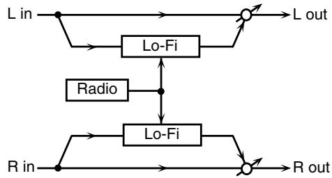
flowchart
graph TD
    A["L in"] --> B["Lo-Fi"]
    B --> C["L out"]
    D["R in"] --> E["Lo-Fi"]
    E --> F["R out"]
    G["Radio"] --> H["Lo-Fi"]
    H --> I["Lo-Fi"]
    B <--> H
| Parameter | Value | Description |
| LoFi Type #1 | 1–9 | Degrades the sound quality. The sound quality grows poorer as this value is increased. |
| Post Filter Type | OFF, LPF, HPF | Type of filterOFF: no filter is usedLPF: cuts the frequency range above the CutoffHPF: cuts the frequency range below the Cutoff |
| Post Filter Cutoff | 200–8000 Hz | Basic frequency of the Post Filter |
| Radio Detune #2 | 0–127 | Simulates the tuning noise of a radio. As this value is raised, the tuning drifts further. |
| Radio Noise Level #3 | 0–127 | Volume of the radio noise |
| Balance #4 | D100:0W–D0:100W | Volume balance between the direct sound (D) and the effect sound (W) |
| Level | 0–127 | Output level |
33: TELEPHONE
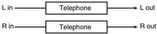
flowchart
graph LR
    A["L in"] --> B["Telephone"]
    C["R in"] --> D["Telephone"]
    B --> E["L out"]
    D --> F["R out"]
| Parameter | Value | Description |
| Voice Quality #1 | 0–15 | Audio quality of the telephone voice |
| Treble #2 | -15– +15 dB | Bandwidth of the telephone voice |
| Balance #3 | D100:0–D0:100W | Volume balance between the direct sound (D) and the effect sound (W) |
| Level | 0–127 | Output level |
34: PHONOGRAPH
Simulates a sound recorded on an analog record and played back on a record player. This effect also simulates the various types of noise that are typical of a record, and even the rotational irregularities of an old turntable.
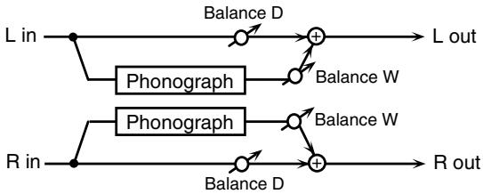
flowchart
graph LR
    L_in --> A["Phonograph"]
    A --> B["Balance D"]
    B --> C["+"]
    C --> L_out
    R_in --> D["Phonograph"]
    D --> E["Balance D"]
    E --> F["+"]
    F --> R_out
    A --> G["Balance W"]
    G --> C
    D --> H["Balance W"]
    H --> F
| Parameter | Value | Description |
| Signal Distortion | 0–127 | Depth of distortion |
| Frequency Range #1 | 0–127 | Frequency response of the playback systemDecreasing this value will produce the impression of an old system with a poor frequency response. |
| Disc Type #2 | LP, EP, SP | Rotational speed of the turntableThis will affect the frequency of the scratch noise. |
| Scratch Noise Level | 0–127 | Amount of noise due to scratches on the record |
| Dust Noise Level | 0–127 | Volume of noise due to dust on the record |
| Hiss Noise Level | 0–127 | Volume of continuous “hiss” |
| Total Noise Level #3 | 0–127 | Volume of overall noise |
| Wow | 0–127 | Depth of long-cycle rotational irregularity |
| Flutter | 0–127 | Depth of short-cycle rotational irregularity |
| Random | 0–127 | Depth of indefinite-cycle rotational irregularity |
| Total Wow/Flutter #4 | 0–127 | Depth of overall rotational irregularity |
| Balance | D100:0W–D0:100W | Volume balance between the direct sound (D) and the effect sound (W) |
| Level | 0–127 | Output level |
35: TAPE ECHO
A virtual tape echo that produces a realistic tape delay sound. This simulates the tape echo section of a Roland RE-201 Space Echo.
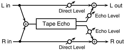
flowchart
graph TD
    A["L in"] --> B["+"]
    C["R in"] --> D["+"]
    B --> E["Tape Echo"]
    D --> E
    E --> F["+"]
    G["L out"] --> H["+"]
    I["R out"] --> J["+"]
    H --> K["Direct Level"]
    J --> L["Direct Level"]
    K --> M["Echo Level"]
    L --> N["Echo Level"]
| Parameter | Value | Description |
| Mode #1 | S, M, L, S+M,S+L, M+L,S+M+L | Combination of playback heads to useSelect from three different heads with different delay times.S: short M: middle L: long |
| Repeat Rate #2 | 0–127 | Tape speedIncreasing this value will shorten the spacing of the delayed sounds. |
| Intensity #3 | 0–127 | Amount of delay repeats |
| Bass | -15– +15 | Boost/cut for the lower range of the echo sound |
| Treble | -15– +15 | Boost/cut for the upper range of the echo sound |
| Head S Pan | L64–63R | Independent panning for the short, middle, and long playback heads |
| Head M Pan | ||
| Head L Pan | ||
| Tape Distortion | 0–5 | Amount of tape-dependent distortion to be addedThis simulates the slight tonal changes that can be detected by signal-analysis equipment. Increasing this value will increase the distortion. |
| Wow/Flutter Rate | 0–127 | Speed of wow/flutter (complex variation in pitch caused by tape wear and rotational irregularity) |
| Wow/Flutter Depth | 0–127 | Depth of wow/flutter |
| Echo Level | 0–127 | Volume of the echo sound |
| Direct Level | 0–127 | Volume of the original sound |
36: FBK PITCH SHIFTER (Feedback Pitch Shifter)
This allows the pitch-shifted sound to be fed back into the effect.
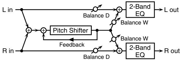
flowchart
graph TD
    L_in --> A["+"]
    R_in --> B["+"]
    A --> C["Balance D"]
    B --> D["Balance D"]
    C --> E["+"]
    D --> F["+"]
    E --> G["Balance W"]
    F --> H["Balance W"]
    G --> I["2-Band EQ"]
    H --> J["2-Band EQ"]
    I --> K["L out"]
    J --> L["R out"]
    M["Pitch Shifter"] --> N["Feedback"]
    N --> A
| Parameter | Value | Description |
| Mode | 1, 2, 3, 4, 5 | Setting a higher value for this parameter results in a slower response, but steadier pitch. |
| Coarse #1 | -24– +12 semi | Adjusts the pitch of the pitch-shifted sound in semitone steps. |
| Fine | -100– +100 cent | Adjusts the pitch of the pitch-shifted sound in 2-cent steps. |
| Delay #2 | 0.0–2000 ms, note | Adjusts the time until the pitch shifted sound is heard. |
| Feedback #3 | -98– +98 % | Adjusts the amount of the pitch-shifted sound that's fed back into the effect. Negative (-) settings invert the phase. |
| Pan | L64–63R | Stereo location of the pitch-shifted sound |
| Low Gain | -15– +15 dB | Gain of the low frequency range |
| High Gain | -15– +15 dB | Gain of the high frequency range |
| Balance #4 | D100:0W–D0:100W | Volume balance between the direct sound (D) and the pitch-shifted sound (W) |
| Level | 0–127 | Output level |
37: 2Vo PITCH SHIFTER (2-Voice Pitch Shifter)
Shifts the pitch of the original sound. This 2-voice pitch shifter has two pitch shifters, and can add two pitch-shifted versions of the original sound.
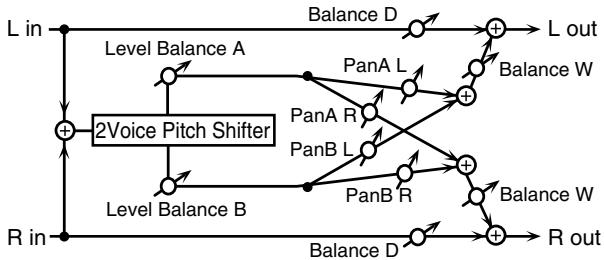
flowchart
graph TD
    L_in --> +1["+"]
    R_in --> +1
    +1 --> LevelBalanceA["Level Balance A"]
    +1 --> LevelBalanceB["Level Balance B"]
    LevelBalanceA --> PanA_L["PanA L"]
    LevelBalanceB --> PanB_L["PanB L"]
    +1 --> PanA_R["PanA R"]
    +1 --> PanB_R["PanB R"]
    +1 --> PanA_L
    +1 --> PanB_L
    +1 --> PanA_R
    +1 --> PanB_L
    +1 --> L_out["L out"]
    +1 --> R_out["R out"]
    L_in --> +2["+"]
    R_in --> +2
    +2 --> LevelBalanceA
    +2 --> LevelBalanceB
    +2 --> LevelBalanceA
    +2 --> LevelBalanceB
    L_out --> +3["+"]
    R_out --> +3
    +3 --> Lout["L out"]
| Parameter | Value | Description |
| Mode | 1, 2, 3, 4, 5 | Setting a higher value for this parameter results in a slower response, but steadier pitch. |
| Coarse A #1 | -24–+12 semi | Adjusts the pitch of Pitch Shift A/B in semitone steps. |
| Coarse B #2 | ||
| Fine A | -100–+100 cent | Adjusts the pitch of Pitch Shift A/B in 2-cent steps. |
| Fine B | ||
| Delay A #3 | 0.0–2000 ms, note | Adjusts the time until Pitch Shift A/B is heard. |
| Delay B #4 | ||
| Pan A | L64–63R | Stereo location of Pitch Shift A/B |
| Pan B | ||
| Level A | A100:0B–A0:100B | Volume balance between Pitch Shift A and Pitch Shift B |
| Level B | ||
| Balance | D100:0W–D0:100W | Volume balance between the direct sound (D) and the pitch shifted sound (W) |
| Level | 0–127 | Output level |
38: GATED REVERB
This is a special type of reverb in which the reverb is cut off without being allowed to decay naturally.
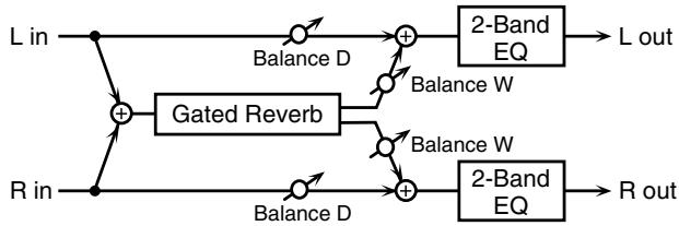
flowchart
graph LR
    L_in --> GatedReverb
    R_in --> GatedReverb
    GatedReverb --> BalanceD1["Balance D"]
    GatedReverb --> BalanceW1["Balance W"]
    GatedReverb --> BalanceW2["Balance W"]
    BalanceD1 --> GatedReverb
    BalanceW1 --> GatedReverb
    BalanceW2 --> GatedReverb
    GatedReverb --> GatedReverb
    GatedReverb --> 2-BandEQ1["2-Band EQ"]
    GatedReverb --> 2-BandEQ2["2-Band EQ"]
    2-BandEQ1 --> Lout["L out"]
    2-BandEQ1 --> Rout["R out"]
| Parameter | Value | Description |
| Type #1 | NORMAL, RE-VERSE | Type of reverbNORMAL: conventional gated reverbREVERSE: backwards reverb |
| Pre Delay #2 | 0.0–100.0 ms | Adjusts the time until the reverb sound is heard. |
| Time #3 | 5–500 ms | Adjusts the time from when the reverb is first heard until it disappears. |
| Pan | L64–63R | Stereo location of Pitch Shift |
| Low Gain | -15–+15 dB | Gain of the low frequency range |
| High Gain | -15–+15 dB | Gain of the high frequency range |
| Balance #4 | D100:0W–D0:100W | Volume balance between the direct sound (D) and the reverb sound (W) |
| Level | 0–127 | Output level |
39: STEREO DELAY
This is a stereo delay.
When Feedback Mode is NORMAL:

flowchart
graph TD
    A["L in"] --> B["+"]
    B --> C["Delay"]
    C --> D["+"]
    D --> E["2-Band EQ"]
    E --> F["L out"]
    G["R in"] --> H["+"]
    H --> I["Delay"]
    I --> J["+"]
    J --> K["2-Band EQ"]
    K --> L["R out"]
    M["Balance D"] --> D
    N["Balance W"] --> D
    O["Feedback Feedback"] --> B
    P["Balance D"] --> H
    Q["Balance W"] --> I
When Feedback Mode is CROSS:
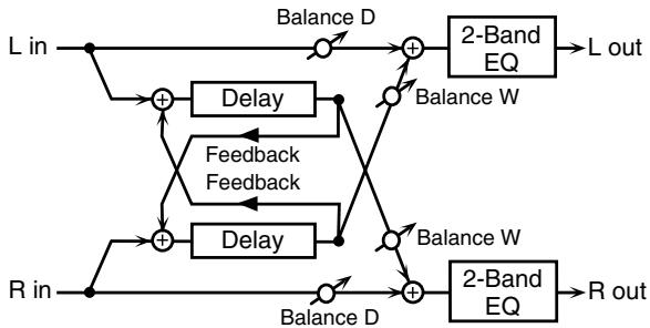
flowchart
graph TD
    A["L in"] --> B["+"]
    C["R in"] --> D["+"]
    B --> E["Delay"]
    D --> F["Delay"]
    E --> G["Balance D"]
    F --> H["Balance D"]
    G --> I["2-Band EQ"]
    H --> J["2-Band EQ"]
    I --> K["L out"]
    J --> L["R out"]
    M["Feedback Feedback"] --> B
    M --> D
    N["Balance W"] --> I
    N --> J
| Parameter | Value | Description |
| Feedback Mode | NORMAL, CROSS | Selects the way in which delay sound is fed back into the effect. (See the figures above.) |
| Delay Left #1 | 0–2000 ms, note | Adjusts the time until the delay sound is heard. |
| Delay Right #2 | ||
| Phase Left | NORMAL, INVERT | Phase of the delay sound |
| Phase Right | ||
| Feedback #3 | -98– +98 % | Adjusts the amount of the delay sound that's fed back into the effect. Negative (-) settings invert the phase. |
| HF Damp | 200–8000 Hz, BYPASS | Adjusts the frequency above which sound fed back to the effect is filtered out. If you don't want to filter out any high frequencies, set this parameter to BYPASS. |
| Low Gain | -15– +15 dB | Gain of the low frequency range |
| High Gain | -15– +15 dB | Gain of the high frequency range |
| Balance #4 | D100:0W–D0:100W | Volume balance between the direct sound (D) and the delay sound (W) |
| Level | 0–127 | Output level |
40: MODULATION DELAY
Adds modulation to the delayed sound.
When Feedback Mode is NORMAL:
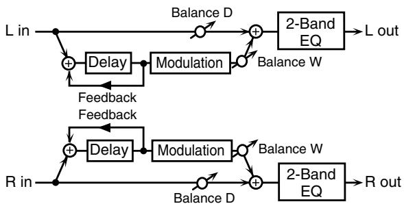
flowchart
graph TD
    A["L in"] --> B["+"]
    B --> C["Delay"]
    C --> D["Modulation"]
    D --> E["+"]
    E --> F["2-Band EQ"]
    F --> G["L out"]
    H["R in"] --> I["+"]
    I --> J["Delay"]
    J --> K["Modulation"]
    K --> L["+"]
    L --> M["2-Band EQ"]
    M --> N["R out"]
    B --> O["Feedback Feedback"]
    I --> P["Feedback Feedback"]
    O --> D
    P --> J
    style A fill:#f9f,stroke:#333
    style H fill:#f9f,stroke:#333
    style M fill:#f9f,stroke:#333
When Feedback Mode is CROSS:
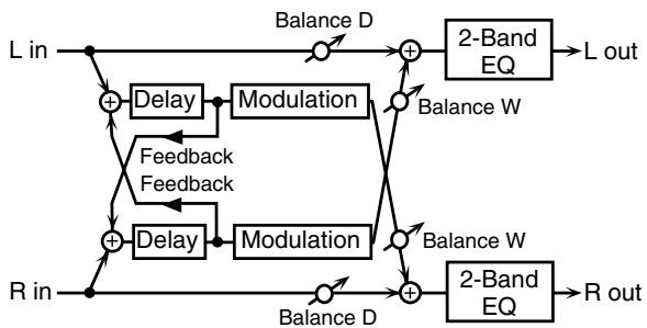
flowchart
graph TD
    L_in["L in"] -->|+| Delay1["Delay"]
    L_in -->|-| Delay2["Delay"]
    Delay1 --> Modulation1["Modulation"]
    Delay2 --> Modulation2["Modulation"]
    R_in["R in"] -->|+| Delay3["Delay"]
    R_in -->|-| Delay4["Delay"]
    Delay3 --> Feedback1["Feedback Feedback"]
    Delay4 --> Feedback2["Feedback Feedback"]
    L_in -->|Balance D| Sum1["+"]
    R_in -->|Balance D| Sum2["+"]
    Sum1 --> BalanceW1["Balance W"]
    Sum2 --> BalanceW2["Balance W"]
    BalanceW1 --> Lout["L out"]
    BalanceW2 --> Rout["R out"]
    2-BandEQ["2-Band EQ"] --> Lout
    2-BandEQ --> Rout
| Parameter | Value | Description |
| Feedback Mode | NORMAL, CROSS | Selects the way in which delay sound is fed back into the effect (See the figures above.) |
| Delay Left #1 | 0–2000 ms, note | Adjusts the time until the delay sound is heard. |
| Delay Right #2 | ||
| Feedback #3 | -98– +98 % | Adjusts the amount of the delay sound that's fed back into the effect. Negative (-) settings invert the phase. |
| HF Damp | 200–8000 Hz, BYPASS | Adjusts the frequency above which sound fed back to the effect is filtered out. If you don't want to filter out any high frequencies, set this parameter to BYPASS. |
| Rate #4 | 0.05–10.00Hz, note | Frequency of modulation |
| Depth | 0–127 | Depth of modulation |
| Phase | 0-180 deg | Spatial spread of the sound |
| Low Gain | -15– +15 dB | Gain of the low frequency range |
| High Gain | -15– +15 dB | Gain of the high frequency range |
| Balance | D100:0W–D0:100W | Volume balance between the direct sound (D) and the delay sound (W) |
| Level | 0–127 | Output level |
41: TRIPLE TAP DELAY
Produces three delay sounds; center, left and right.
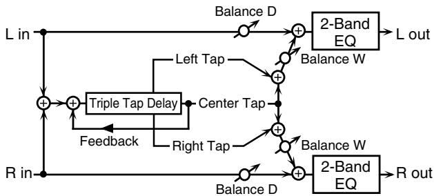
flowchart
graph TD
    A["L in"] --> B["+"]
    C["R in"] --> D["+"]
    B --> E["Triple Tap Delay"]
    D --> F["Feedback"]
    E --> G["Center Tap"]
    F --> H["Right Tap"]
    G --> I["+"]
    H --> J["+"]
    I --> K["Balance D"]
    J --> L["Balance W"]
    K --> M["2-Band EQ"]
    L --> N["2-Band EQ"]
    M --> O["L out"]
    N --> P["R out"]
| Parameter | Value | Description |
| Left #1Center #2Right #3 | 0–4000 ms, note | Adjusts the time until the delay sound is heard. |
| Feedback #4 | -98– +98 % | Adjusts the amount of the delay sound that's fed back into the effect. Negative (-) settings invert the phase. |
| HF Damp | 200–8000 Hz, BYPASS | Adjusts the frequency above which sound fed back to the effect is filtered out. If you do not want to filter out any high frequencies, set this parameter to BYPASS. |
| Left/Right/Center Level | 0–127 | Volume of each delay |
| Low Gain | -15– +15 dB | Gain of the low frequency range |
| High Gain | -15– +15 dB | Gain of the high frequency range |
| Balance | D100:0W–D0:100W | Volume balance between the direct sound (D) and the delay sound (W) |
| Level | 0–127 | Output level |
42: QUADRUPLE TAP DELAY
This effect has four delays.
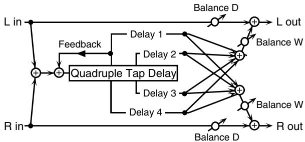
flowchart
graph TD
    A["L in"] --> B["+"]
    C["R in"] --> D["+"]
    B --> E["Quadruple Tap Delay"]
    D --> E
    E --> F["Delay 1"]
    E --> G["Delay 2"]
    E --> H["Delay 3"]
    E --> I["Delay 4"]
    F --> J["Balance D"]
    G --> K["Balance W"]
    H --> L["Balance W"]
    I --> M["Balance D"]
    J --> N["L out"]
    K --> O["R out"]
    L --> P["Balance W"]
    M --> Q["Balance D"]
    N --> R["Feedback"]
    O --> S["Feedback"]
Stereo location of each delay
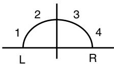
| Parameter | Value | Description |
| Delay 1–4#1–#4 | 0–4000 ms, note | Adjusts the time until the delay sound is heard. |
| Level 1–4 | 0–127 | Volume of each delay |
| FeedbackHF Damp | -98– +98 %200–8000 Hz, BYPASS | Adjusts the amount of the delay sound that's fed back into the effect. Negative (-) settings invert the phase.Adjusts the frequency above which sound fed back to the effect is filtered out. If you do not want to filter out any high frequencies, set this parameter to BYPASS. |
| Balance | D100:0W–D0:100W | Volume balance between the direct sound (D) and the delay sound (W) |
| Level | 0–127 | Output level |
43: MULTI TAP DELAY
This effect provides four delays. Each of the Delay Time parameters can be set to a note length based on the selected tempo. You can also set the panning and level of each delay sound.
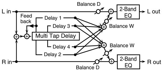
flowchart
graph TD
    A["L in"] --> B["+"]
    C["R in"] --> B
    B --> D["Multi Tap Delay"]
    D --> E["Delay 1"]
    D --> F["Delay 2"]
    D --> G["Delay 3"]
    D --> H["Delay 4"]
    D --> I["Balance D"]
    I --> J["2-Band EQ"]
    J --> K["L out"]
    D --> L["Balance W"]
    L --> M["2-Band EQ"]
    M --> N["R out"]
    style A fill:#f9f,stroke:#333
    style C fill:#f9f,stroke:#333
    style B fill:#ccf,stroke:#333
    style D fill:#cfc,stroke:#333
    style I fill:#fcc,stroke:#333
    style J fill:#cff,stroke:#333
    style K fill:#ffc,stroke:#333
    style L fill:#ffc,stroke:#333
    style M fill:#ffc,stroke:#333
    style N fill:#ffc,stroke:#333
| Parameter | Value | Description |
| Delay 1–4#1–#4 | 0–4000 ms, note | Adjusts the time until Delays 1–4 are heard. |
| Pan 1–4 | L64–63R | Stereo location of Delays 1–4 |
| Level 1–4 | 0–127 | Output level of Delays 1–4 |
| Feedback | -98– +98 % | Adjusts the amount of the delay sound that's fed back into the effect. Negative (-) settings invert the phase. |
| HF Damp | 200–8000 Hz, BYPASS | Adjusts the frequency above which sound fed back to the effect is filtered out. If you don't want to filter out any the high frequencies, set this parameter to BYPASS. |
| Low Gain | -15– +15 dB | Gain of the low frequency range |
| High Gain | -15– +15 dB | Gain of the high frequency range |
| Balance | D100:0W–D0:100W | Volume balance between the direct sound (D) and the effect sound (W) |
| Level | 0–127 | Output level |
44: REVERSE DELAY
Adds the reverse of the input sound as a delay.
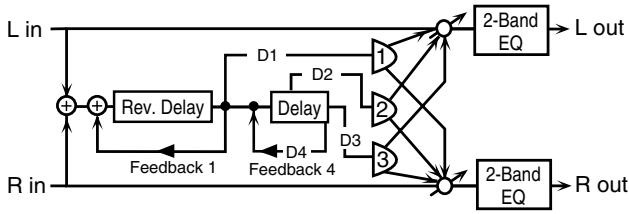
flowchart
graph TD
    A["L in"] --> B["+"]
    B --> C["Rev. Delay"]
    C --> D["Delay"]
    D --> E["D1"]
    D --> F["D2"]
    D --> G["D3"]
    E --> H["1"]
    F --> I["2"]
    G --> J["3"]
    H --> K["2-Band EQ"]
    I --> K
    J --> K
    K --> L["L out"]
    M["R in"] --> N["+"]
    N --> O["Feedback 1"]
    O --> P["Delay"]
    P --> Q["D4"]
    Q --> R["Feedback 4"]
    R --> S["1"]
    R --> T["2"]
    R --> U["3"]
    S --> V["2-Band EQ"]
    T --> V
    U --> V
    V --> W["R out"]
| Parameter | Value | Description |
| Threshold | 0–127 | Volume level at which the reverse delay begins |
| Delay 1–4 (Delay 1 #1) | 0-2000 ms, note | Adjusts the time until Delays 1–4 are heard. |
| Feedback 1 #2 | -98– +98 % | Adjusts the amount of the delay sound that's fed back into the effect. Negative (-) settings invert the phase. |
| Feedback 4 | ||
| HF Damp 1 | 200–8000 Hz, BYPASS | Adjusts the frequency above which sound fed back to the effect is filtered out. If you do not want to filter out any high frequencies, set this parameter to BYPASS. |
| HF Damp 4 | ||
| Pan 1–3 (Pan 1 #3) | L64–63R | Stereo location of Delays 1–3 sound |
| Level 1–3 | 0–127 | Output level of Delays 1–3 sound |
| Balance #4 | D100:0W–D0:100W | Volume balance between the direct sound (D) and the effect sound (W) |
| Low Gain | -15– +15 dB | Gain of the low frequency range |
| High Gain | -15– +15 dB | Gain of the high frequency range |
| Level | 0–127 | Output level |
45: SHUFFLE DELAY
Adds a shuffle to the delay sound, giving the sound a bouncy delay effect with a swing feel.
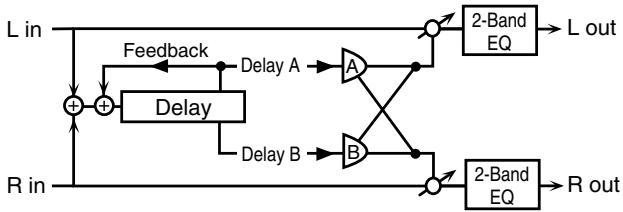
flowchart
graph TD
    L_in --> +1["+"]
    R_in --> +1
    +1 --> Delay1["Delay A"]
    +1 --> Delay2["Delay B"]
    Delay1 --> A["A"]
    Delay2 --> B["B"]
    A --> Out1["2-Band EQ"]
    B --> Out2["2-Band EQ"]
    Out1 --> L_out["L out"]
    Out2 --> R_out["R out"]
    Feedback --> +1
    Delay1 --> +2["+"]
    Delay2 --> +3["+"]
    2-BandEQ1 --> Out1
    2-BandEQ2 --> Out2
| Parameter | Value | Description |
| Delay #1 | 0–4000 ms, note | Adjusts the time until the delay sound is heard. |
| Shuffle Rate #2 | 0–100 % | Adjusts the ratio (as a percentage) of the time that elapses before Delay B sounds relative to the time that elapses before the Delay A sounds.When set to 100%, the delay times are the same. |
| Pan A/B | L64–63R | Stereo location of Delay A/B |
| Level Balance | A100:0B–A0:100B | Volume balance between Delay A and Delay B |
| Feedback #3 | -98– +98 % | Adjusts the amount of the delay that's fed back into the effect. Negative (-) settings invert the phase. |
| Acceleration | 0–15 | Adjusts the time over which the Delay Time changes from the current setting to its specified new setting. |
| HF Damp | 200–8000 Hz, BYPASS | Adjusts the frequency above which sound fed back to the effect is filtered out. If you don't want to filter out any high frequencies, set this parameter to BYPASS. |
| Low Gain | -15– +15 dB | Gain of the low frequency range |
| High Gain | -15– +15 dB | Gain of the high frequency range |
| Balance #4 | D100:0W–D0:100W | Volume balance between the direct sound (D) and the effect sound (W) |
| Level | 0–127 | Output level |
46: TIME CONTROL DELAY
This lets you smoothly vary the delay time. As the delay time is varied, the pitch will change correspondingly; lengthening the delay time will lower the pitch, and shortening it will raise the pitch.
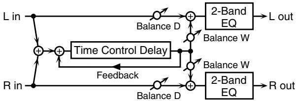
flowchart
graph TD
    L_in --> A["+"]
    R_in --> B["+"]
    A --> C["Time Control Delay"]
    B --> C
    C --> D["+"]
    E["Balance D"] --> F["2-Band EQ"]
    G["Balance W"] --> H["2-Band EQ"]
    I["Balance W"] --> J["2-Band EQ"]
    K["Balance D"] --> L["+"]
    M["Balance W"] --> N["+"]
    O["Balance D"] --> P["+"]
    Q["L out"] --> F
    R_out --> H
    S["Feedback"] --> B
| Parameter | Value | Description |
| Delay #1 | 0–4000 ms, note | Adjusts the time until the delay is heard. |
| Feedback #2 | -98– +98 % | Adjusts the amount of the delay that's fed back into the effect. Negative (-) settings invert the phase. |
| Acceleration #3 | 0–15 | Adjusts the time over which the Delay Time changes from the current setting to a specified new setting.The rate of change for the Delay Time directly affects the rate of pitch change. |
| HF Damp | 200–8000 Hz, BYPASS | Adjusts the frequency above which sound fed back to the effect is filtered out. If you do not want to filter out any high frequencies, set this parameter to BYPASS. |
| Pan | L64–63R | Stereo location of the delay |
| Low Gain | -15– +15 dB | Gain of the low frequency range |
| High Gain | -15– +15 dB | Gain of the high frequency range |
| Balance #4 | D100:0W–D0:100W | Volume balance between the direct sound (D) and the delay sound (W) |
| Level | 0–127 | Output level |
47: TIME SKIP DELAY
A delay that changes the delay time in stair-step fashion.
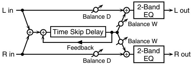
flowchart
graph TD
    L_in --> A["+"]
    R_in --> B["+"]
    A --> C["Balance D"]
    B --> D["Balance D"]
    C --> E["+"]
    D --> F["+"]
    E --> G["2-Band EQ"]
    F --> H["2-Band EQ"]
    G --> I["L out"]
    H --> J["R out"]
    K["Time Skip Delay"] --> E
    K --> F
    K --> H
    L_in --> K
    R_in --> K
    Feedback --> K
    K --> E
    K --> F
    K --> H
| Parameter | Value | Description |
| Delay #1 | 0–4000 ms, note | Adjusts the time until the delay is heard. |
| Skip Rate | 0.05–10.0 Hz, note | Frequency at which the delay time will change |
| Feedback #2 | -98– +98 % | Adjusts the amount of the delay sound that's fed back into the effect. Negative (-) settings invert the phase. |
| Acceleration #3 | 0–15 | Adjusts the time over which the Delay Time changes from the current setting to its specified new setting. |
| HF Damp | 200–8000 Hz, BYPASS | Adjusts the frequency above which sound fed back to the effect is filtered out. If you don't want to filter out any high frequencies, set this parameter to BYPASS. |
| Pan | L64–63R | Stereo location of the delay |
| Low Gain | -15– +15 dB | Gain of the low frequency range |
| High Gain | -15– +15 dB | Gain of the high frequency range |
| Balance #4 | D100:0W–D0:100W | Volume balance between the direct sound (D) and the delay sound (W) |
| Level | 0–127 | Output level |
About the STEP RESET function
07:STEP FILTER
28:SLICER
The above two types contain a sixteen-step sequencer.
For these effect types, you can use multi-effect control ("Multi-effect control (Effects/MFX Ctrl screen)" (p. 29)) to reset the step sequence to its beginning.
To do this, set the Control Assign setting for that effect type to "Step Reset."
For example, if you want to use the modulation lever to control Step Reset, you would make the following settings.
MFX Control–Source: CC01: MODULATION
MFX Control–Sens: +63
Control Assign: Step Reset
With these settings, the step sequence will be reset to the beginning each time you operate the modulation lever.
About Note
Some parameters (such as Rate or Delay Time) can be set in terms of a note value instead of a time value.
Such parameters provide a Sync switch (Sync SW) that allows you to switch between setting the parameter as a note value or as a numerical value.
If you want to set it as a note value, set the Sync SW to ON.
* If a parameter that's chosen in Control Assign for multi-effect control has its Sync SW to ON, you won't be able to use multi-effect control to control that parameter.
| Value | Description |
| 1/64T( ♪3 ) | Sixty-fourth-note triplet |
| 1/64( ♪ ) | Sixty-fourth note |
| 1/32T( ♪3 ) | Thirty-second-note triplet |
| 1/32( ♪ ) | Thirty-second note |
| 1/16T( ♪3 ) | Sixteenth-note triplet |
| 1/32.( ♪ ) | Dotted thirty-second note |
| 1/16( ♪ ) | Sixteenth note |
| 1/8T( ♪3 ) | Eighth-note triplet |
| 1/16.( ♪ . ) | Dotted sixteenth note |
| 1/8( ♪ ) | Eighth note |
| 1/4T( ♪3 ) | Quarter-note triplet |
| 1/8.( ♪ . ) | Dotted eighth note |
| 1/4( ♪ ) | Quarter note |
| 1/2T( ♪3 ) | Half-note triplet |
| 1/4.( ♪ . ) | Dotted quarter note |
| 1/2( ♪ ) | Half note |
| 1/1T( Ⓤ3 ) | Whole-note triplet |
| 1/2.( ♪ . ) | Dotted half note |
| 1/1( ⓞ ) | Whole note |
| 2/1T( Ⓤ13 ) | Double-note triplet |
| 1/1.( ⓞ · ) | Dotted whole note |
| 2/1( Ⓤ1 ) | Double note |
ARX-01 DRUMS
Maximum Polyphony
128 voices (varies according to the sound generator load)
Parts
1 part
User Memory
Drum Kits: 50 (including pre-loaded kits)
Effects
EQ/COMP: 24 systems (1 system par instrument)
Multi-Effects(MFX): 1 system, 47 types
Reverb: 1 system, 4 types
Customize Functions
SNARE, KICK, TOM:
Shell Depth, Head Tuning, Muffling, Mic Position, Buzz
HIHAT, CYMBAL, RIDE:
Size, Sustain
E.DRUM:
Tune, Decay, Cutoff, Resonance and more
Miscellaneous
24-channel Mixer, Flam/Roll effect for each tone
Accessories
Owner's manual
Screwdriver
* In the interest of product improvement, the specifications and/or appearance of this unit are subject to change without prior notice.
A
Assign Type 21
B
basic screen 19
Buzz 22
C
Comp/EQ screen 26
Control Assign 29
E
Effects/MFX Ctrl screen 29
Effects/MFX screen 29
Effects/Reverb screen 31
Effects/Routing screen 28
F
Flam/Roll screen 24
G
Group Faders 19
H
Head Tuning 22
|
Inst Number 21
Inst Type 21
K
Kit
Save 20
Select 19
Kit Init 33
L
Layer Tone 21
M
MFX
2Vo PITCH SHIFTER 58
AUTO PAN 43
AUTO WAH 39
COMPRESSOR 50
DISTORTION 48
ENHANCER 36
FBK PITCH SHIFTER 57
GATE 52
GATED REVERB 58
GUITAR AMP SIM 49
HEXA-CHORUS 45
HUMANIZER 40
ISOLATOR 37
LIMITER 51
LOFI COMPRESS 54
LOFI NOISE 53
LOFI RADIO 54
LOW BOOST 37
MODULATION DELAY 60
MULTI TAP DELAY 62
OVERDRIVE 48
PHASER 40
PHONOGRAPH 55
QUADRUPLE TAP DELAY 61
REVERSE DELAY 63
RING MODULATOR 42
ROTARY 44
SHUFFLE DELAY 63
SLICER 51
SPACE-D 46
SPECTRUM 36
STEP FILTER 39
STEP FLANGER 48
STEP PHASER 41
STEREO CHORUS 46
STEREO DELAY 59
STEREO EQ 35
STEREO FLANGER 47
STEREO PHASER 41
SUPER FILTER 38
TAPE ECHO 56
TELEPHONE 55
TIME CONTROL DELAY 64
TIME SKIP DELAY 65
TREMOLO 43
TREMOLO CHORUS 45
TRIPLE TAP DELAY 61
MFX Control Sens 30
MFX Control Source 30
MFX Ctrl screen 29
MFX Output Level 28
MFX Reverb Send Level 28
MFX screen 29
MFX Type 28-29
Mic Position 22
Mixer screen 28
Muffling 22
multi-effect 28
Multi-Effects 34
Mute 27
Mute Group 21
Mute Key Type 32
O
Output Assign 27
Output Level 27
Output screen 27
P
Pitch 22
R
Reverb Level 28
Reverb screen 31
Reverb Send Level 27
Reverb Type 28
roll 24
Routing screen 28
S
Shell Depth 22
Size 22
Sustain 22
T
Tone
Customize 22
Select 21
Tone Init 33
Tone screen 21
Tone/Comp/EQ screen 26
Tone/Customize screen 22
Tone/Output screen 27
Type 31
U
Utility screen 33
For the USA
FEDERAL COMMUNICATIONS COMMISSION RADIO FREQUENCY INTERFERENCE STATEMENT
This equipment has been tested and found to comply with the limits for a Class B digital device, pursuant to Part 15 of the FCC Rules. These limits are designed to provide reasonable protection against harmful interference in a residential installation. This equipment generates, uses, and can radiate radio frequency energy and, if not installed and used in accordance with the instructions, may cause harmful interference to radio communications. However, there is no guarantee that interference will not occur in a particular installation. If this equipment does cause harmful interference to radio or television reception, which can be determined by turning the equipment off and on, the user is encouraged to try to correct the interference by one or more of the following measures:
– Reorient or relocate the receiving antenna.
– Increase the separation between the equipment and receiver.
- Connect the equipment into an outlet on a circuit different from that to which the receiver is connected.
- Consult the dealer or an experienced radio/TV technician for help.
This device complies with Part 15 of the FCC Rules. Operation is subject to the following two conditions:
(1) this device may not cause harmful interference, and
(2) this device must accept any interference received, including interference that may cause undesired operation.
Unauthorized changes or modification to this system can void the users authority to operate this equipment. This equipment requires shielded interface cables in order to meet FCC class B Limit.
For Canada
NOTICE
This Class B digital apparatus meets all requirements of the Canadian Interference-Causing Equipment Regulations.
AVIS
DECLARATION OF CONFORMITY
Compliance Information Statement
Model Name : ARX-01
Type of Equipment : Expansion Board
Responsible Party : Roland Corporation U.S.
Address: 5100 S. Eastern Avenue, Los Angeles, CA 90040-2938
Telephone : (323) 890-3700
For EU Countries

This symbol indicates that in EU countries, this product must be collected separately from household waste, as defined in each region. Products bearing this symbol must not be discarded together with household waste.
DE Dieses Symbol bedeutet, dass dieses Produkt in EU-Ländern getrennt vom Hausmüll gesammelt werden muss gemäß den regionalen Bestimmungen. Mit diesem Symbol gekennzeichnete Produkte dürfen nicht zusammen mit den Hausmüll entsorgt werden.
FR Ce symbole indique que dans les pays de l'Union européenne, ce produit doit être collecté séparément des ordures ménagères selon les directives en vigueur dans chacun de ces pays. Les produits portant ce symbole ne doivent pas être mis au rebut avec les ordures ménagères.
Questo simbolo indica che nei paesi della Comunità europea questo prodotto deve essere smaltito separatamente dai normali rifiuti domestici, secondo la legislazione in vigore in ciascun paese. I prodotti che riportano questo simbolo non devono essere smaltiti insieme ai rifiuti domestici. Ai sensi dell'art. 13 del D.Lgs. 25 luglio 2005 n. 151.
ES Este símbolo indica que en los países de la Unión Europea este producto debe recogerse aparte de los residuos domésticos, tal como esté regulado en cada zona. Los productos con este símbolo no se deben depositar con los residuos domésticos.
PT Este símbolo indica que nos países da UE, a recolha deste produto deverá ser feita separadamente do lixo doméstico, de acordo com os regulamentos de cada região. Os produtos que apresentem este símbolo não deverão ser eliminados juntamente com o lixo doméstico.
NL Dit symbool geeft aan dat in landen van de EU dit product gescheiden van huishoudelijk afval moet worden aangeboden, zoals bepaald per gemeente of regio. Producten die van dit symbool zijn voorzien, mogen niet samen met huishoudelijk afval worden verwijderd.
DK Dette symbol angiver, at i EU-lande skal dette produkt opsamles adskilt fra husholdningsaffald, som defineret i hver enkelt region. Produkter med dette symbol må ikke smides ud sammen med husholdningsaffald.
NO Dette symbolet indikerer at produktet må behandles som spesialavfall i EU-land, iht. til retningslinjer for den enkelte regionen, og ikke kastes sammen med vanlig husholdningsavfall. Produkter som er merket med dette symbolet, må ikke kastes sammen med vanlig husholdningsavfall.
SE Symbolen anger att i EU-länder måste den här produkten kasseras separat från hushållsavfall, i enlighet med varje regions bestämmelser. Produkter med den här symbolen får inte kasseras tillsammans med hushållsavfall.
Tämä merkintä ilmaisee, että tuote on EU-maissa kerättävä erillään kotitalousjätteistä kunkin alueen voimassa olevien määräysten mukaisesti. Tällä merkinnällä varustettuja tuotteita ei saa hävittää kotitalousjätteiden mukana.
Ez a szimbólum azt jelenti, hogy az Európai Unióban ezt a terméket a háztartási hulladéktól elkülönítve, az adott régióban érvényes szabályozás szerint kell gyűjteni. Az ezzel a szimbólmmal ellátott termékeket nem szabad a háztartási hulladék közé dobni.
PL Symbol oznacza, że zgodnie z regulacjami w odpowiednim regionie, w krajach UE produktu nie należy wyrzucać z odpadami domowymi. Produktów opatrzonych tym symbolem nie można utylizować razem z odpadami domowymi.
Tento symbol udává, že v zemích EU musí být tento výrobek sbírán odděleně od domácího odpadu, jak je určeno pro každý region. Výrobky nesoucí tento symbol se nesmí vyhazovat spolu s domácím odpadem.
SK Tento symbol vyjadruje, že v krajinách EÚ sa musí zber tohto produktu vykonávať oddelene od domového odpadu, podľa nariadení platných v konkrétnej krajine. Produkty s týmto symbolom sa nesmú vyhadzovať spolu s domovým odpadom.
EE See sümbol näitab, et EL-i maades tuleb see toode olemprügist eraldi koguda, nii nagu on igas piirkonnas määratletud. Selle sümboliga märgitud tooteid ei tohi ära visata koos olmeprügiga.
LT Šis simbolis rodo, kad ES šalyse šis produktas turi būti surenkamas atskirai nuo buitinių atliekų, kaip nustatyta kiekviename regione. Šiuo simboliu paženklinti produktai neturi būti išmetami kartu su buitinėmis atliekomis.
LV Šis simbols norāda, ka ES valstīs šo produktu jāievāc atseviški no mājsaimniecības atkritumiem, kā noteikts katrā regionā. Produktus ar šo simbolu nedrīkst izmest kopā ar mājsaimniecības atkritumiem.
Si Ta simbol označuje, da je treba proizvod v državah EU zbirati ločeno od gospodinjskih odpadkov, tako kot je določeno v vsaki regiji. Proizvoda s tem znakom ni dovoljeno odlagati skupaj z gospodinjskimi odpadki.
To σύμβολο αυτό υποδηλώνει ότι στις χώρες της Ε.Ε. το συγκεχριμένο προϊόν πρέπει να συλλέγεται χωριστά από τα υπόλοπα οικιακά απορρίμματα, συφωνα με σσα προβλέπονται σε κάθε περιοχή. Τα προϊόντα που φέρουν το συγκεχριμένο σύμβολο δεν πρέπει να απορρίπονται μαζί με τα οικιακά απορρίμματα.
有关产品中所含有害物质的说明
Al Fanny Trading Office 9, EBN Hagar Al Askalany Street, ARD E1 Golf, Heliopolis, Cairo 11341, EGYPT TEL: (022)-418-5531
REUNION
Maison FO - YAM Marcel 25 Rue Jules Hermann, Chaudron - BP79 97 491 Ste Clotilde Cedex, REUNION ISLAND TEL: (0262) 218-429
SOUTH AFRICA
T.O.M.S. Sound & Music (Pty)Ltd. 2 ASTRON ROAD DEN JOHANNESBURG ZA 2 SOUTH AFRICA TEL: (011)417 3400
Paul Bothner(PTY)Ltd. Royal Cape Park, Unit 24 Londonderry Road, Ottery 7800 Cape Town, SOUTH AFRICA TEL: (021) 799 4900
ASIA
CHINA
Roland Shanghai Electronics Co., Ltd. 5F. No.1500 Pingliang Road Shanghai 200090, CHINA TEL: (021) 5580-0800
Roland Shanghai Electronics Co., Ltd.
(BEIJING OFFICE)
10F. No.18 3 Section Anhuaxil Chaoyang District Beijing 100011 CHINA
TEL: (010) 6426-5050
HONG KONG
Tom Lee Music Co., Ltd. Service Division 22-32 Pun Shan Street, Ts Wan, New Territories, HONG KONG TEL: 2415 0911
Parsons Music Ltd. 8th Floor, Railway Plaza, 39 Chatham Road South, T.S.T, Kowloon, HONG KONG TEL: 2333 1863
INDIA
Rivera Digitec (India) Pvt. Ltd. 411, Nirman Kendra Mahalaxmi Flats Compound Off. Dr. Edwin Moses Road, Mumbai-400011, INDIA TEL: (022) 2493 9051
INDONESIA
PT Citra IntiRama Jl. Cideng Timur No. 15J-15O Jakarta Pusat INDONESIA TEL: (021) 6324170
KOREA
Cosmos Corporation 1461-9, Seocho-Dong, Seocho Ku, Seoul, KOREA TEL: (02) 3486-8855
MALAYSIA
Roland Asia Pacific Sdn. Bhd. 45-1, Block C2, Jalan PJU 1/39, Dataran Prima, 47301 Petaling Jaya, Selangor, MALAYSIA TEL: (03) 7805-3263
VIET NAM
Suoi Nhac Company, Ltd 370 Cach Mang Thang Tam St. Dist.3, Ho Chi Minh City, VIET NAM TEL: 9316540
PHILIPPINES
G.A. Yupangco & Co. Inc. 339 Gil J. Puyat Avenue Makati, Metro Manila 1200, PHILIPPINES TEL: (02) 899 9801
SINGAPORE
SWEE LEE MUSIC COMPANY PTE. LTD. 150 Sims Drive, SINGAPORE 387381 TEL: 6846-3676
TAIWAN
ROLAND TAIWAN ENTERPRISE CO., LTD. Room 5, 9fl. No. 112 Chung Shan N.Road Sec.2, Taipei, TAIWAN, R.O.C. TEL: (02) 2561 3339
THAILAND
Theera Music Co., Ltd. 100-108 Soi Verng Nakornkasem, New Road, Sumpantawongse, Bangkok 10100 THAILAND TEL: (02) 224-8821
AUSTRALIA/ NEW ZEALAND
AUSTRALIA/ NEW ZEALAND
Roland Corporation Australia Pty., Ltd. 38 Campbell Avenue Dee Why West. NSW 209 AUSTRALIA
For Australia Tel: (02) 9982 8266 For New Zealand Tel: (09) 3098 715
CENTRAL/LATIN AMERICA
ARGENTINA
Instrumentos Musicales S.A. Av.Santa Fe 2055 (1123) Buenos Aires ARGENTINA TEL: (011) 4508-2700
BARBADOS
A&B Music Supplies LTD 12 Webster Industrial Park Wildey, St.Michael, Barbados TEL: (246)430-1100
BRAZIL
Roland Brasil Ltda. Rua San Jose, 780 Sala B Parque Industrial San Jose Cotia - Sao Paulo - SP, BRAZIL TEL: (011) 4615 5666
CHILE
Comercial Fancy II S.A. Rut.: 96.919.420-1 Nataniel Cox #739, 4th Floor Santiago - Centro, CHILE TEL: (02) 688-9540
COLOMBIA
Centro Musical Ltda. Cra 43 B No 25 A 41 Bododega 9 Medellin, Colombia TEL: (574)3812529
COSTA RICA
JUAN Bansbach Instrumentos Musicales Ave.1. Calle 11, Apartado 10237, San Jose, COSTA RICA TEL: 258-0211
CURACAO
Zeelandia Music Center Inc. Orionweg 30 Curacao, Netherland Antilles TEL:(305)5926866
DOMINICAN REPUBLIC
Instrumentos Fernando Giraldez Calle Proyecto Central No.3 Ens.La Esperilla Santo Domingo, Dominican Republic TEL:(809) 683 0305
ECUADOR
Mas Musika Rumichaca 822 y Zaruma Guayaquil - Ecuador TEL:(593-4)2302364
EL SALVADOR
OMNI MUSIC 75 Avenida Norte y Final Alameda Juan Pablo II, Edificio No.4010 San Salvador, EL SALVADOR TEL: 262-0788
GUATEMALA
Casa Instrumental Calzada Roosevelt 34-01, zona 11 Ciudad de Guatemala Guatemala TEL:(502) 599-2888
HONDURAS
Almacen Pajaro Azul S.A. de C.V. BO.Paz Barahona 3 Ave.11 Calle S.O San Pedro Sula, Honduras TEL: (504) 553-2029
MARTINIQUE
155, New National Road
Patras 26442, GREECE
TEL: 2610 435400
HUNGARY
Roland East Europe Ltd.
Warehouse Area 'DEPO' Pf.83
H-2046 Torokbalint,
HUNGARY
TEL: (23) 511011
IRELAND
Roland Ireland
G2 Calmount Park, Calmount
Avenue, Dublin 12
Republic of IRELAND
TEL: (01) 4294444
ITALY
Roland Italy S. p. A.
Danvik Center 28, 2 tr.
S-131 30 Nacka SWEDEN
TEL: (0)8 702 00 20
SWITZERLAND
Roland (Switzerland) AG
Atlantic Close, Swansea
Enterprise Park, SWANSEA
SA7 9FJ,
UNITED KINGDOM
TEL: (01792) 702701
MIDDLE EAST
BAHRAIN
Moon Stores
No.1231&1249 Rumaytha
Building Road 3931, Manama
339 BAHRAIN
TEL: 17 813 942
IRAN
MOCO INC.
No.41 Nike St., Dr.Shariyati Ave.,
Roberoye Cerahe Mirdamad
Tehran, IRAN
TEL: (021)-2285-4169
ISRAEL
Halilit P. Greenspoon & Sons
Ltd.
8 Retzif Ha'alia Hashnia St.
Tel-Aviv-Yafo ISRAEL
TEL: (03) 6823666
JORDAN
Al-Yousifi Service Center
P.O.Box 126 (Safat) 13002
KUWAIT
TEL: 00 965 802929
LEBANON
Chahine S.A.L.
George Zeidan St., Chahine
Bldg., Achrafieh, P.O.Box: 16-5857
Beirut, LEBANON
TEL: (01) 20-1441
OMAN
TALENTZ CENTRE L.L.C.
Malatan House No.1
Al Noor Street, Ruwi
SULTANATE OF OMAN
TEL: 2478 3443
QATAR
Al Emadi Co. (Badie Studio &
Stores)
P.O. Box 62, Doha, QATAR
TEL: 4423-554
SAUDI ARABIA
aDawliah Universal
Electronics APL
Behind Pizza Inn
Prince Turkey Street
aDawliah Building,
PO BOX 2154,
Alkhobar 31952
SAUDI ARABIA
TEL: (03) 8643601
SYRIA
Technical Light & Sound
Center
Rawda, Abdul Qader Jazairi St.
Bldg. No. 21, P.O.BOX 13520,
Damascus, SYRIA
TEL: (011) 223-5384
TURKEY
ZUHAL DIS TICARET A.S.
Galip Dede Cad. No.37
Beyoglu - Istanbul / TURKEY
TEL: (0212) 249 85 10
U.A.E.
Zak Electronics & Musical
Instruments Co. L.L.C.
Zabeel Road, Al Sherooq Bldg.,
No. 14, Ground Floor, Dubai,
U.A.E.
TEL: (04) 3360715
NORTH AMERICA
CANADA
Roland Canada Ltd.
(Head Office)
5480 Parkwood Way
Richmond B. C., V6V 2M4
CANADA
TEL: (604) 270 6626
Roland Canada Ltd.
(Toronto Office)
170 Admiral Boulevard
Mississauga On L5T 2N6
CANADA
TEL: (905) 362 9707
U. S. A.
Roland Corporation U.S.
5100 S. Eastern Avenue
Los Angeles, CA 90040-2938,
U.S.A.
TEL: (323) 890 3700
Roland Corporation
Roland
SuperNATURAL Expansion Board
ARX-01
DRUMS
取扱説明書
natural_image
Technical line drawing of a mechanical clamp or bracket assembly (no text or symbols)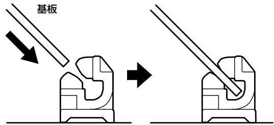
ツメなしホルダー
natural_image
Technical illustration of a mechanical component with mounting holes and a close-up view showing internal components (no text or symbols)natural_image
Diagram showing a device with mounting holes and a mechanical component, no text or symbols presentnatural_image
Technical line drawing of a mechanical assembly with no visible text or symbolsNote On 最初のロール音
flowchart
graph LR
    A["L in"] --> B["Ring Mod"]
    B --> C["2-Band EQ"]
    C --> D["L out"]

flowchart
graph LR
    A["R in"] --> B["Ring Mod"]
    B --> C["2-Band EQ"]
    C --> D["R out"]
flowchart
graph LR
    A["L in"] --> B["Gate"]
    B --> C["L out"]

flowchart
graph LR
    A["R in"] --> B["Gate"]
    B --> C["R out"]
flowchart
graph LR
    L_in --> GatedReverb
    R_in --> GatedReverb
    GatedReverb --> BalanceD1["Balance D"]
    GatedReverb --> BalanceW1["Balance W"]
    GatedReverb --> BalanceW2["Balance W"]
    BalanceD1 --> GatedReverb
    BalanceW1 --> GatedReverb
    BalanceW2 --> GatedReverb
    GatedReverb --> GatedReverb
    GatedReverb --> 2-BandEQ1["2-Band EQ"]
    2-BandEQ1 --> Lout["L out"]
    GatedReverb --> 2-BandEQ2["2-Band EQ"]
    2-BandEQ2 --> Rout["R out"]
Flam/Roll Type Lower 96
Flam/Roll Type Upper 96
Flam/Roll 画面 96
G
2Vo PITCH SHIFTER 129
AUTO PAN 115
AUTO WAH 111
COMPRESSOR 121
DISTORTION 120
ENHANCER 108
FBK PITCH SHIFTER 128
GATE 123
GATED REVERB 130
GUITAR AMP SIM 120
HEXA-CHORUS 116
HUMANIZER 112
ISOLATOR 109
LIMITER 122
LOFI COMPRESS 125
LOFI NOISE 124
LOFI RADIO 125
LOW BOOST 109
MODULATION DELAY 131
MULTI TAP DELAY 134
OVERDRIVE 119
PHASER 112
PHONOGRAPH 126
QUADRUPLE TAP DELAY 133
REVERSE DELAY 135
RING MODULATOR 114
ROTARY 115
SHUFFLE DELAY 135
SLICER 122
SPACE-D 117
SPECTRUM 108
STEP FILTER 111
STEP FLANGER 119
STEP PHASER 113
STEREO CHORUS 117
STEREO DELAY 130
STEREO EQ 107
STEREO FLANGER 118
STEREO PHASER 113
SUPER FILTER 110
TAPE ECHO 127
TELEPHONE 126
TIME CONTROL DELAY 136
TIME SKIP DELAY 137
TREMOLO 114
TREMOLO CHORUS 116
TRIPLE TAP DELAY 132
MFX Control Sens 1 \~ 4 102
MFX Control Source 1 \~ 4 102
MFX Ctrl 画面 101
MFX Output Level 100
MFX Reverb Send Level 100
MFX Type 100\~101
MFX タイプ 106
MFX 画面 101
Mic Position 94
Mixer 画面 100
Muffling 94
Mute Group 93
Mute Key Type 104
Mute Switch 99
0
Output Assign 99
Output Level 99
Output 画面 99
P
Pan 99
Pre Delay 103
R
Reverb Level 100
Reverb Send Level 99
Reverb Type 100、103
Reverb 画面 103
Routing 画面 100
S
Shell Depth 94
Size 103
T
Time 103