
DIF-AT24 - Audio Interface ROLAND - Free user manual and instructions
Find the device manual for free DIF-AT24 ROLAND in PDF.
| Product type | Digital audio interface |
| Brand | Roland |
| Model | DIF-AT24 |
| Format | 1U rack-mountable |
| Dimensions (W x D x H) | 482 x 150 x 44 mm |
| Weight | 2.0 kg |
| Power supply | 9 V DC power adapter (included) |
| Power consumption | 5 W |
| Converts | AES/EBU to S/PDIF and vice versa |
| Audio resolution | 24-bit / 96 kHz |
| Digital inputs | 1 x AES/EBU (XLR), 1 x S/PDIF (coaxial RCA) |
| Digital outputs | 1 x AES/EBU (XLR), 1 x S/PDIF (coaxial RCA) |
| Clock input | Word clock (BNC) |
| Clock output | Word clock (BNC) |
| Sample rate conversion | Yes, built-in |
| Care and cleaning | Soft, dry cloth. Do not use solvents. |
| Safety | Do not expose to moisture. Use only the provided adapter. |
| Spare parts and repairability | Power adapter available. For repairs, contact an authorized Roland service center. |
| General information | Designed for studio or sound reinforcement use. |
Frequently Asked Questions - DIF-AT24 ROLAND
User questions about DIF-AT24 ROLAND
0 question about this device. Answer the ones you know or ask your own.
Ask a new question about this device
Download the instructions for your Audio Interface in PDF format for free! Find your manual DIF-AT24 - ROLAND and take your electronic device back in hand. On this page are published all the documents necessary for the use of your device. DIF-AT24 by ROLAND.
USER MANUAL DIF-AT24 ROLAND
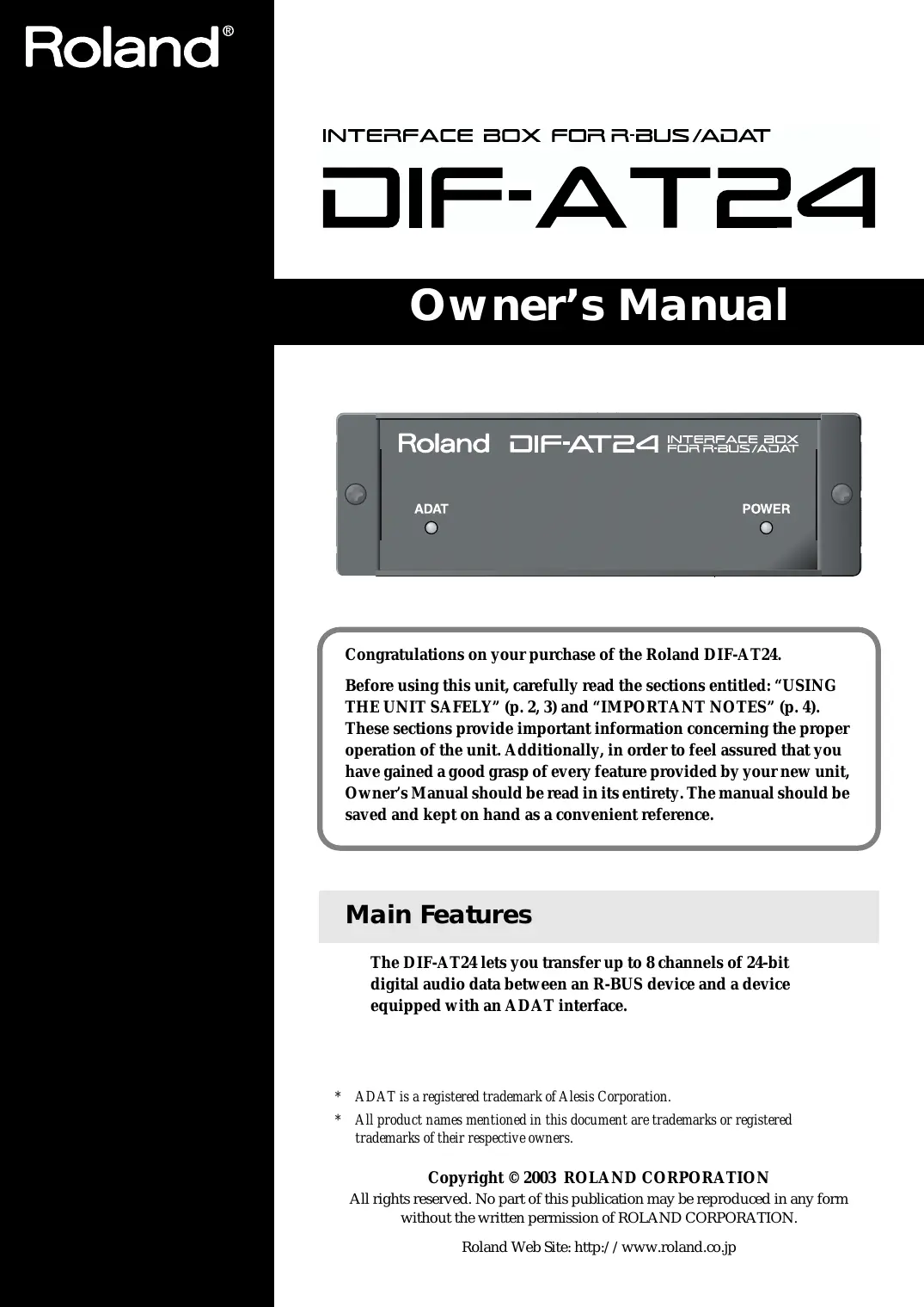
INTERFACE BOX FOR R-BUS/ADAT
DIF-AT24
Owner's Manual
Congratulations on your purchase of the Roland DIF-AT24.
Before using this unit, carefully read the sections entitled: "USING THE UNIT SAFELY" (p. 2, 3) and "IMPORTANT NOTES" (p. 4). These sections provide important information concerning the proper operation of the unit. Additionally, in order to feel assured that you have gained a good grasp of every feature provided by your new unit, Owner's Manual should be read in its entirety. The manual should be saved and kept on hand as a convenient reference.
Main Features
The DIF-AT24 lets you transfer up to 8 channels of 24-bit digital audio data between an R-BUS device and a device equipped with an ADAT interface.
- ADAT is a registered trademark of Alesis Corporation.
- All product names mentioned in this document are trademarks or registered trademarks of their respective owners.
Copyright © 2003 ROLAND CORPORATION
All rights reserved. No part of this publication may be reproduced in any form without the written permission of ROLAND CORPORATION.
USING THE UNIT SAFELY
INSTRUCTIONS FOR THE PREVENTION OF FIRE, ELECTRIC SHOCK, OR INJURY TO PERSONS
About WARNING and CAUTION Notices
| ▲WARNING | Used for instructions intended to alert the user to the risk of death or severe injury should the unit be used improperly. |
| ▲CAUTION | Used for instructions intended to alert the user to the risk of injury or material damage should the unit be used improperly. * Material damage refers to damage or other adverse effects caused with respect to the home and all its furnishings, as well to domestic animals or pets. |
About the Symbols
| △ | The △ symbol alerts the user to important instructions or warnings. The specific meaning of the symbol is determined by the design contained within the triangle. In the case of the symbol at left, it is used for general cautions, warnings, or alerts to danger. |
| ◎ | The ⊙ symbol alerts the user to items that must never be carried out (are forbidden). The specific thing that must not be done is indicated by the design contained within the circle. In the case of the symbol at left, it means that the unit must never be disassembled. |
| ◆ | The ● symbol alerts the user to things that must be carried out. The specific thing that must be done is indicated by the design contained within the circle. In the case of the symbol at left, it means that the power-cord plug must be unplugged from the outlet. |
ALWAYS OBSERVE THE FOLLOWING
WARNING
Before using this unit, make sure to read the instructions below, and the Owner's Manual.

- Do not open or perform any internal modifications on the unit.

- Do not attempt to repair the unit, or replace parts within it (except when this manual provides specific instructions directing you to do so). Refer all servicing to your retailer, the nearest Roland Service Center, or an authorized Roland distributor, as listed on the "Information" page.

- Never use or store the unit in places that are:

- Subject to temperature extremes (e.g., direct sunlight in an enclosed vehicle, near a heating duct, on top of heat-generating equipment); or are

- Damp (e.g., baths, washrooms, on wet floors); or are
- Humid; or are
- Exposed to rain; or are
- Dusty; or are
-
Subject to high levels of vibration.
-
Make sure you always have the unit placed so it is level and sure to remain stable. Never place it on stands that could wobble, or on inclined surfaces.

WARNING
- Do not allow any objects (e.g., flammable material, coins, pins); or liquids of any kind (water, soft drinks, etc.) to penetrate the unit.


- Immediately turn the power off, and request servicing by your retailer, the nearest Roland Service Center, or an authorized Roland distributor, as listed on the "Information" page when:

- If smoke or unusual odor occurs
- Objects have fallen into, or liquid has been spilled onto the unit; or
- The unit has been exposed to rain (or otherwise has become wet); or
-
The unit does not appear to operate normally or exhibits a marked change in performance.
-
In households with small children, an adult should provide supervision until the child is capable of following all the rules essential for the safe operation of the unit.

- Protect the unit from strong impact. (Do not drop it!)

CAUTION
- Try to prevent cords and cables from becoming entangled. Also, all cords and cables should be placed so they are out of the reach of children.

- Never climb on top of, nor place heavy objects on the unit.

- Disconnect all cords coming from external devices before moving the unit.

For EU Countries
CE
This product complies with the requirements of European Directive 89/336/EEC.
For the USA
FEDERAL COMMUNICATIONS COMMISSION RADIO FREQUENCY INTERFERENCE STATEMENT
This equipment has been tested and found to comply with the limits for a Class B digital device, pursuant to Part 15 of the FCC Rules. These limits are designed to provide reasonable protection against harmful interference in a residential installation. This equipment generates, uses, and can radiate radio frequency energy and, if not installed and used in accordance with the instructions, may cause harmful interference to radio communications. However, there is no guarantee that interference will not occur in a particular installation. If this equipment does cause harmful interference to radio or television reception, which can be determined by turning the equipment off and on, the user is encouraged to try to correct the interference by one or more of the following measures:
Reorient or relocate the receiving antenna.
- Increase the separation between the equipment and receiver.
- Connect the equipment into an outlet on a circuit different from that to which the receiver is connected.
- Consult the dealer or an experienced radio/TV technician for help.
This device complies with Part 15 of the FCC Rules. Operation is subject to the following two conditions:
(1) This device may not cause harmful interference, and
(2) This device must accept any interference received, including interference that may cause undesired operation.
Unauthorized changes or modification to this system can void the users authority to operate this equipment.
This equipment requires shielded interface cables in order to meet FCC class B Limit.
For Canada
NOTICE
This Class B digital apparatus meets all requirements of the Canadian Interference-Caising Equipment Regulations.
AVIS
In addition to the items listed under "USING THE UNIT SAFELY" on page 2, please read and observe the following:
Power Supply
- Before connecting this unit to other devices, turn off the power to all units. This will help prevent malfunctions and/or damage to speakers or other devices.
Placement
- This device may interfere with radio and television reception. Do not use this device in the vicinity of such receivers.
- Noise may be produced if wireless communications devices, such as cell phones, are operated in the vicinity of this unit. Such noise could occur when receiving or initiating a call, or while conversing. Should you experience such problems, you should relocate such wireless devices so they are at a greater distance from this unit, or switch them off.
- When moved from one location to another where the temperature and/or humidity is very different, water droplets (condensation) may form inside the unit. Damage or malfunction may result if you attempt to use the unit in this condition. Therefore, before using the unit, you must allow it to stand for several hours, until the condensation has completely evaporated.
Maintenance
- For everyday cleaning wipe the unit with a soft, dry cloth or one that has been slightly dampened with water. To remove stubborn dirt, use a cloth impregnated with a mild, non-abrasive detergent. Afterwards, be sure to wipe the unit thoroughly with a soft, dry cloth.
- Never use benzine, thinners, alcohol or solvents of any kind, to avoid the possibility of discoloration and/or deformation.
Additional Precautions
- Use a reasonable amount of care when using the unit's switches and when using its jacks and connectors. Rough handling can lead to malfunctions.
-
When connecting / disconnecting all cables, grasp the connector itself—never pull on the cable. This way you will avoid causing shorts, or damage to the cable's internal elements.
-
To avoid disturbing your neighbors, try to keep the unit's volume at reasonable levels (especially when it is late at night).
- When you need to transport the unit, package it in the box (including padding) that it came in, if possible. Otherwise, you will need to use equivalent packaging materials.
Copyright
- When exchanging audio signals through a digital connection with an external instrument, this unit can perform recording without being subject to the restrictions of the Serial Copy Management System (SCMS). This is because the unit is intended solely for musical production, and is designed not to be subject to restrictions as long as it is used to record works (such as your own compositions) that do not infringe on the copyrights of others. (SCMS is a feature that prohibits second-generation and later copying through a digital connection. It is built into MD recorders and other consumer digital-audio equipment as a copyright-protection feature.)
- Do not use this unit for purposes that could infringe on a copyright held by a third party. We assume no responsibility whatsoever with regard to any infringements of third-party copyrights arising through your use of this unit.
When connecting to the VM-7100/7200
- The DIF-AT24 will not operate correctly if the VM-7100/7200 system version is earlier than 1.7.
Use the following procedure to check the system version, and be sure to update to system version 1.7 or later.
For details on updating, please contact the nearest Roland office or service center.
- To check the version -
- Connect the VM-7100/7200 to the VM-C7100/C7200.
- Turn on the power to start up the system.
- Hold down [On Display] and press numeric key [0]. The version display screen will appear, with an indication like the following: "Unit X Version: 1.XXX"
- Note the version number shown in "1.XXX"
Main Features 1
USING THE UNIT SAFELY 2
IMPORTANT NOTES 4
Panel descriptions 6
Front Panel 6
Rear Panel 6
Turning the power on/off. 7
Turning the power on. 7
Turning the power off 7
Connections and settings 8
Connection example 1 Connecting the VS-2400CD and a computer. 8
Connection example 2 Connecting the VS-2400CD and a computer. 10
Connection example 3 Connecting the VS-2400CD and an ADAT device 12
Connection example 4 Connecting the VS-2400CD with an ADAT device and BRC 13
Connection example 5 Using the DIF-AT24 as an additional MIDI OUT for the MV-8000. 15
Specifications
DIF-AT24: Interface Box for R-BUS/ADAT
| Sampling Frequency | 44.1/48kHz |
| Audio Data Format | 16/20/24 bit |
| Indicators | Power indicator ADAT indicator |
| Connectors | R-BUS connector ADAT optical connectors in, out MIDI connectors in, out |
| Power Supply | Supplied from connected R-BUS device |
| Dimensions | 138 (W) x 197 (D) x 43 (H) mm 5-7/16 (W) x 7-13/16 (D) x 1-3/4 (H) inches |
| Weight | 0.5 kg 1 lb 2 oz |
| Accessories | R-BUS cable (1 m) Owner's manual |
- In the interest of product improvement, the specifications and/or appearance of this unit are subject to change without prior notice.
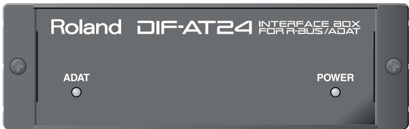
Front Panel
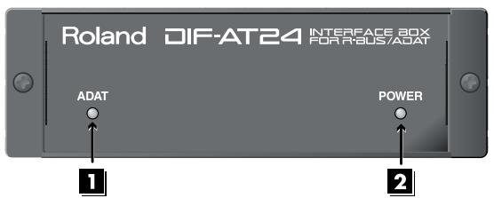
1 ADAT indicator
This indicator will light green if an ADAT interface signal is being input to the ADAT digital IN connector.
2 POWER indicator
When the R-BUS device connected to the R-BUS connector is powered up, this indicator will light red to indicate that power is being supplied to the DIF-AT24.
- Power is supplied to the DIF-AT24 via the R-BUS connector.
Rear Panel
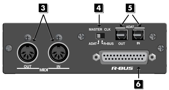
3 MIDI IN/OUT connectors
These are used mainly for MTC synchronization.
MEMO
The data that is transmitted from the MIDI OUT connector will depend on the settings of the R-BUS device connected to the R-BUS connector.
4 MASTER CLK (Master clock) switch
This switches the master clock (sampling clock) synchronization.
| MASTER CLK switch | Master clock device |
| Set to [R-BUS] | When using the R-BUS device connected to the R-BUS connector as the master clock. |
| Set to [ADAT] | When using the digital device connected to the ADAT OUT/IN connector as the master clock |
5 ADAT OUT/IN (ADAT digital out/in) connector
This is the ADAT digital interface.
It allows eight channels of digital audio data to be transferred between the DIF-AT24 and an ADAT-compatible digital device.
6 R-BUS connector
Provides for the input/output of eight channels of digital audio data, thus allowing the exchange of data between the DIF-AT24 and an R-BUS device to take place. Also transmits/receives synchronization signals.
- Power is supplied to the DIF-AT24 via the R-BUS connector.
NOTE
- Connect only an R-BUS device to the R-BUS connector. You must never connect a device with a SCSI, RS-232C, or parallel interface. Even though the connectors on such devices may look similar, they are incompatible, and damage and/or malfunction could result if you attempt their connection. Also, you must use only a special R-BUS cable to make connections.
- You must turn off the power of the R-BUS device before connecting or disconnecting the R-BUS cable. If you connect or disconnect the cable while power is being supplied, the external R-BUS device will stop working correctly, and the DIF-AT24 or the external R-BUS device may also be damaged.
- The specifications for "R-BUS" are identical to those of RMDB2 and RMDB II. You can use it with any device that is marked "RMDB2" or "RMDB II."
- R-BUS (RMDB2) is not compatible with the older RMDB specification.
Turning the power on/off
Turning the power on
Before you turn each device on, make sure that all devices are connected correctly.
Once the connections have been completed, turn on power to your various devices in the order specified. By turning on devices in the wrong order, you risk causing malfunction and/ or damage to speakers and other devices.
1.
Turn on the power of your R-BUS device.
When power is supplied to the DIF-AT24, its power indicator will light.
2
Turn on the power of your computer, ADAT device, etc.
3
Turn on the power of your audio device like audio mixers etc.
Turning the power off
1
Turn off the power of your audio device like audio mixers etc.
2
Turn off the power of your computer, ADAT device, etc.
3
Turn off the power of your R-BUS device.
Power will no longer be supplied, and the DIF-AT24's power indicator will go out.
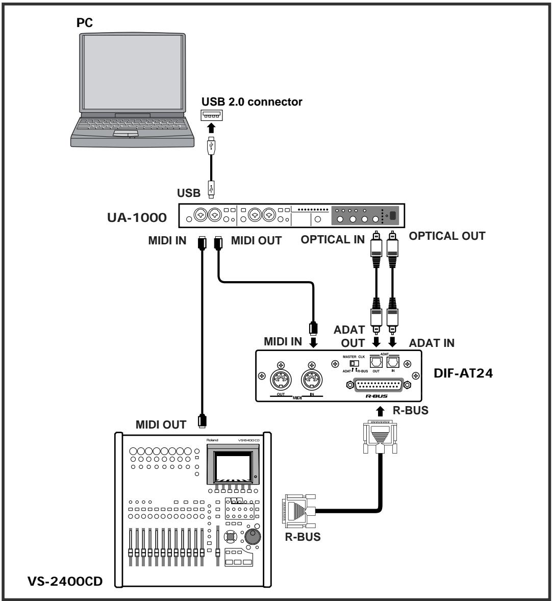
Connection example 1
Connecting the VS-2400CD and a computer
Here's an example of synchronization with computer-based sequencer software or the VS-2400CD functioning as the master.
Make connections as shown in the diagram. This example uses the UA-1000 to perform input/output with the computer via USB 2.0.

To prevent malfunction and/or damage to speakers or other devices, always turn down the volume, and turn off the power on all devices before making any connections.
Settings
Sampling Frequency settings
Set the sampling frequency of your sequencer software, the VS-2400CD, and the UA-1000 to the same setting (44.1 kHz or 48 kHz).
Master Clock settings
| Master clock device | VS-2400CD setting | DIF-AT24 MASTER CLK switch |
| VS-2400CD | PROJECT PARAMETER screen ○ MASTER CLOC.......INT | R-BUS |
| Sequencer software | PROJECT PARAMETER screen ○ MASTER CLOC.......R-BUS | ADAT |

You'll also need to set the Master Clock for your sequencer software. For details on this setting, refer to the owner's manual for your sequencer software.
Synchronization settings
Set the VS-2400CD's parameters as follows.
MMC settings
| If using the sequencer software as the MMC master | If using the VS-2400CD as the MMC master |
| MIDI PARAMETER screen | MIDI PARAMETER screen |
| ○ SysEx. Rx. Sw............ On | ○ MIDI OUT/THRU............ Out |
| ○ MMC MODE............ SLAVE | ○ SysEx. Tx. Sw............ On |
| ○ MMC SOURCE............ R-BUS | ○ MMC MODE............ MASTER |
MTC settings
| If using the sequencer software as the MMC master | If using the VS-2400CD as the MMC master |
| SYNC PARAMETER screen | SYNC PARAMETER screen |
| ○ SYNC MODE..............................EXT | ○ SYNC MODE......................INT |
| ○ EXT SYNC SOURCE......................R-BUS | ○ FRAME RATE......................Select the MTC type.* |
| ○ FRAME RATE......................Same setting as the software.* | ○ MIDI OUT SYNC Gen......................MTC |
- Check the specifications of your sequencer software, and set your software and the VS-2400CD to the same frame rate.

In order to synchronize operation with your sequencer software, you'll also need to make settings in the sequencer software. For details on these settings, refer to the owner's manual for your sequencer software.
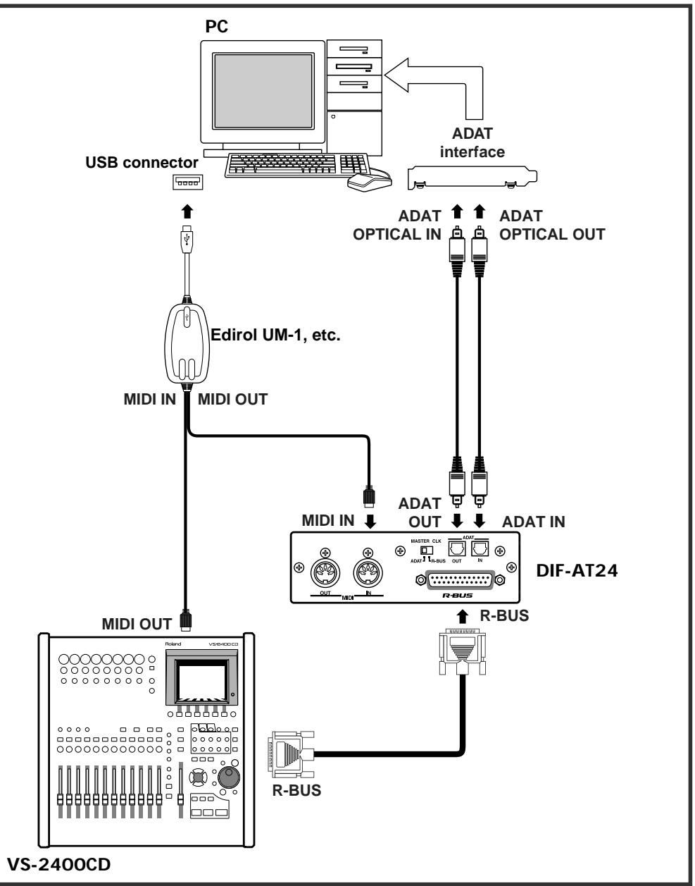
Connection example 2
Connecting the VS-2400CD and a computer
Here's an example of synchronization with computer-based sequencer software or the VS-2400CD functioning as the master.
Make connections as shown in the diagram. This example uses an ADAT interface and MIDI interface connected to your computer.

To prevent malfunction and/or damage to speakers or other devices, always turn down the volume, and turn off the power on all devices before making any connections.
Settings
Sampling Frequency settings
Set the sampling frequency of your sequencer software and the VS-2400CD to the same setting (44.1 kHz or 48 kHz).
Master Clock settings
| Master clock device | VS-2400CD setting | DIF-AT24 MASTER CLK switch |
| VS-2400CD | PROJECT PARAMETER screen ○ MASTER CLOC.......INT | R-BUS |
| Sequencer software | PROJECT PARAMETER screen ○ MASTER CLOC.......R-BUS | ADAT |

You'll also need to set the Master Clock for your sequencer software. For details on this setting, refer to the owner's manual for your sequencer software.
Synchronization settings
Set the VS-2400CD's parameters as follows.
MMC settings
| If using the sequencer software as the MMC master | If using the VS-2400CD as the MMC master |
| MIDI PARAMETER screen | MIDI PARAMETER screen |
| ○ SysEx. Rx. Sw............ On | ○ MIDI OUT/THRU............ Out |
| ○ MMC MODE............ SLAVE | ○ SysEx. Tx. Sw............ On |
| ○ MMC SOURCE............ R-BUS | ○ MMC MODE............ MASTER |
MTC settings
| If using the sequencer software as the MMC master | If using the VS-2400CD as the MMC master |
| SYNC PARAMETER screen | YNC PARAMETER screen |
| ○ SYNC MODE..............................EXT | ○ SYNC MODE......................INT |
| ○ EXT SYNC SOURCE......................R-BUS | ○ FRAME RATE......................Select the MTC type.* |
| ○ FRAME RATE......................Same setting as the software.* | ○ MIDI OUT SYNC Gen......................MTC |
- Check the specifications of your sequencer software, and set your software and the VS-2400CD to the same frame rate.

In order to synchronize operation with your sequencer software, you'll also need to make settings in the sequencer software. For details on these settings, refer to the owner's manual for your sequencer software.
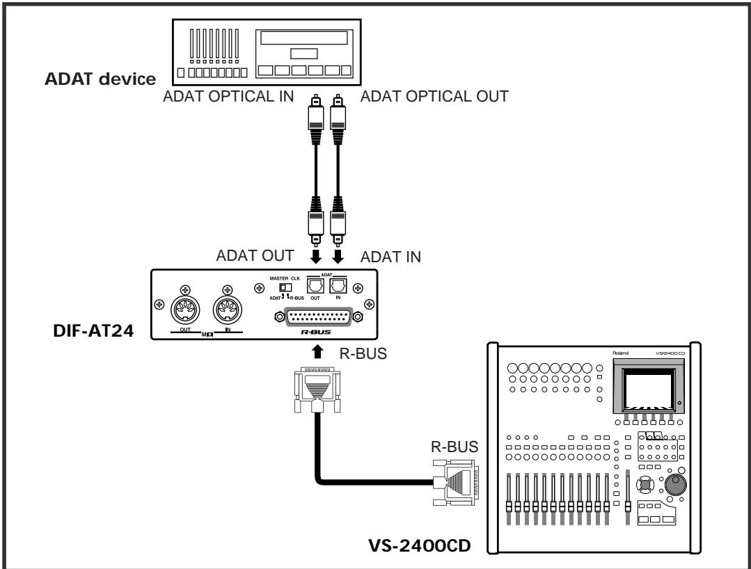
Connection example 3
Connecting the VS-2400CD and an ADAT device
This example allows digital audio signals to be transferred. Make connections as shown in the diagram.

To prevent malfunction and/or damage to speakers or other devices, always turn down the volume, and turn off the power on all devices before making any connections.
Settings
Sampling Frequency settings
Set the sampling frequency of the VS-2400CD and ADAT device to the same setting (44.1 kHz or 48 kHz).
Master Clock settings
| Master clock device | VS-2400CD setting | DIF-AT24 MASTER CLK switch |
| VS-2400CD | PROJECT PARAMETER screen ○ MASTER CLOC......INT | R-BUS |
| ADAT device | PROJECT PARAMETER screen ○ MASTER CLOC......R-BUS | ADAT |

You'll also need to set the Master Clock for the ADAT device. For details on this setting, refer to the owner's manual for the ADAT device.
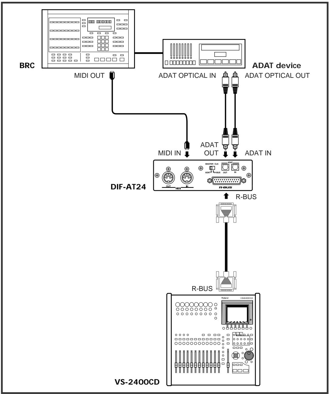
Connection example 4
Connecting the VS-2400CD with an ADAT device and BRC
The BRC is used to operate the VS-2400CD and ADAT device in synchronization. Make connections as shown in the diagram.

To prevent malfunction and/or damage to speakers or other devices, always turn down the volume, and turn off the power on all devices before making any connections.
Settings
Sampling Frequency settings
Set the sampling frequency of the VS-2400CD and ADAT device to the same setting (48 kHz).
Master Clock settings
| Master clock device | VS-2400CD setting | DIF-AT24 MASTER CLK switch |
| VS-2400CD | PROJECT PARAMETER screen ○ MASTER CLOC.......INT | R-BUS |
| ADAT device | PROJECT PARAMETER screen ○ MASTER CLOC.......R-BUS | ADAT |

You'll also need to set the Master Clock for the ADAT device. For details on this setting, refer to the owner's manual for the ADAT device.
Synchronization settings
Set the VS-2400CD's parameters as follows.
MIDI PARAMETER screen
SysEx.Rx.Sw.On
MMC MODE..SLAVE
MMC SOURCER-BUS
SYNC PARAMETER screen
SYNC MODE.EXT
EXT SYNC SOURCER-BUS
FRAME RATE.... Same setting as the software.*
BRC settings
Press [EDIT] → [GEN SYNC] → [GEN SYNC].
The screen will indicate "Generate Sync."
2 Use [A] to select "MID: MTC" and press [EDIT].
[EDIT] will go dark.
3 Press [GEN SYNC]. [GEN SYNC] will light, and the BRC will output MTC.
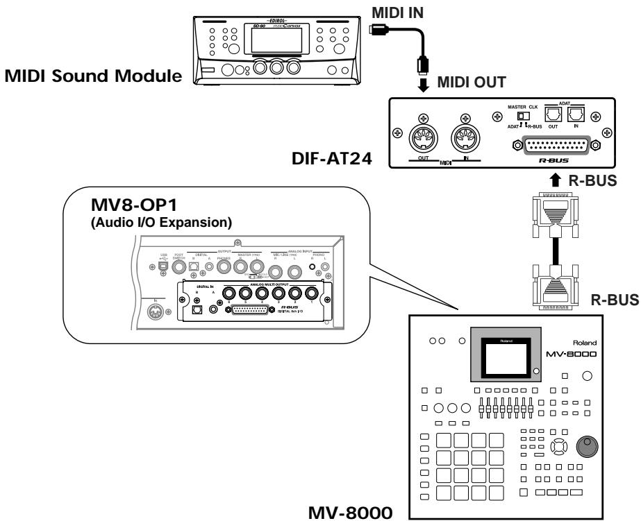
Connection example 5
Using the DIF-AT24 as an additional MIDI OUT for the MV-8000
Make connections as shown in the diagram.

To prevent malfunction and/or damage to speakers or other devices, always turn down the volume, and turn off the power on all devices before making any connections.

In order to make these connections, the MV8-OP1 (audio I/O expansion; sold separately) must be installed in the MV-8000.
Settings
MV-8000 settings

Press the [SEQUENCE] button.
The SEQUENCE screen will appear.

Move the cursor to the track whose MIDI settings you want to make.

Press function button [F1 (Track Param)].
The TRACK PARAMETER screen will appear.

In the TRACK PARAMETER screen, move the cursor to "MIDI," and select "R-1"–"R-16" as the MIDI channel on which the track will be transmitted via R-BUS.
Information
When you need repair service, call your nearest Roland Service Center or authorized Roland distributor in your country as shown below.
AFRICA
EGYPT
Al Fanny Trading Office
9 EBN Hagar Al Askalyan Street,
ARD E1 Golf, Heliopolis,
Cairo 11341, Egypt
TEL: 20-2-417-1828
REUNION
Maison FO-YAM Marcel 25 Rue Jules Hermann, Chaudron-BP79 97491 Ste Clotilde Cedex, REUNION ISLAND TEL: (0262)218-429
SOUTH AFRICA
That Other Music Shop (PTY) Ltd.
11 Melle St., Braamfontein, Johannesburg, SOUTH AFI
P.O.Box 32918, Braamfontein 201
Johannesburg, SOUTH AFRICA
TEL: (011) 403 4105
Paul Bothner (PTY) Ltd
17 Werdmuller Centre,
Main Road, Claremont 7708
SOUTH AFRICA
P.O.BOX 23032, Claremont 7735, SOUTH AFRICA
TEL: (021) 674 4030
ASIA
CHINA
Roland Shanghai Electronics Co.,Ltd. SF.No.1500 Pingliang Road Shanghai 200090,CHINA TEL:(021)5580-0800
Roland Shanghai Electronics Co.,Ltd. (BEIJING OFFICE)
10F. No.18 Anhuxili
Chaoyang District, Beijing 100011
CHINA
TEL: (010) 6426-5050
Roland Shanghai Electronics Co., Ltd.
(GUANGZHOU OFFICE)
2/F, No.30 Si You Nan Er He Yi
Xiang, Wu Yang Xin Cheng, Guangzhou 510600, CHINA
Tel: (020) 8736-0428
HONG KONG
Tom Lee Music Co., Ltd.
Service Division
22-32 Pun Shan Street, Tsuen Wan, New Territories,
HONG KONG
TEL: 2415 0911
Parsons Music Ltd.
8th Floor, Railway Plaza, 39 Chatham Road South, T.S.T. Kowloon, HONG KONG
TEL: 2331 1863
INDIA
Rivera Digitec (India) Pvt. Ltd. 409. Niraner Kendra Mahalaxmi Flats Compound Off. Dr. Edwin Moses Road, Mumbai-400011, INDIA
TEL: (022) 2493 9051
INDONESIA
PT Citra IntiRama
JL, Cideng Timur No. 15J-150
Jakarta Pusat
INDONESIA
TEL: (021) 6324170
KOREA
Cosmos Corporation 1461.9, Seocho-Dong, Seocho Ku, Seoul, KOREA TEL: (02) 3486-8855
MALAYSIA
BENTLEY MUSIC SDN BHD 140 & 142, Jalan Bukit Bintang 55100 Kuala Lumpur, MALAYSIA TEL: (03) 2144-3333
PHILIPPINES
G.A. Yupangco & Co. Inc.
339 Gill I. Puyat Avenue
Makati, Metro Manila 1200,
PHILIPPINES
TEL: (02) 889 9801
SINGAPORE
Swee Lee Company
150 Sims Drive,
SINGAPORE 387381
TEL: 6846-3676
CRISTOFORI MUSIC PTE LTD
Blk 3014, Bedok Industrial Park E, #02-2148, SINGAPORE 489980
TEL: 6243-9555
TAIWAN
ROLAND TIAWAN
ENTERPRISE CO., LTD.
Room 5, 901, No. 112 Chung Shan N Road, Sec.2, Taipei, TAIWAN, R.O.C.
TEL: (02) 2561 3339
THAILAND
Theera Music Co., Ltd. 330 Veng NakornKasem, Sol 2, Bangkok 10100. THAILAND TEL: (02) 2248821
VIETNAM
Saigon Music
Suite DP-8
40 Ba Huyen Thanh Quan Street
1500 Ho Chi Minh City, VIH
AUSTRALIA/ NEW ZEALAND
AUSTRALIA
Roland Corporation Australia Pty., Ltd. 38 Campbell Avenue Dee Why West. NSW 2099 AUSTRALIA TEL: (02) 9882 8266
NEW ZEALAND Roland Corporation Ltd.
32 Shaddock Street, Mount Eden, Auckland, NEW ZEALAND
TEL: (09) 3098 715
CENTRAL/LATINAMERICA
ARGENTINA
Instrumentsos Musicales S.
Av.Santa Fe 2055
(1123) Buenos Aires
ARGENTINA
TEL: (011) 4508-2700
BRAZIL
Roland Brasil Ltda
Rua San Jose, 780 Sala B
Parque Industrial San Jose
Cotia - São Paulo - SP, BRAZIL.
COSTA RICA
JUAN Bansbach
Instrumentos Musicales
Ave.1. Calle 11, Apartado 10237, San Jose, COSTA RICA
TEL: 258-0211
CHILE
Commercial Fancy II S.A.
Rut.: 96,919,420-1
Nataniel Cox #739, 4th Floor
Santiago - Centro, CHILE
TEL: (02) 688-9540
EL SALVA
OMNI MUSIC
75 Avenida Norte y Final
Alameda Juan Pablo II,
Edificio No.4010 San Salvador,
EL SALVADOR
TEL: 262-0788
MEXICO
Casa Veerkamp, s.a. de c.v. Av. Toluca No. 323, Col. Olivar de los Pedres 01780 Mexico D.F. MEXICO TEL: (53) 5668-6699
PANAMA
SUPRO MUNDIAL, S.A.
Boulevard Andrews, Albrook, Panama City, REP. DE PANAMA
TEL: 315-0101
PARAGUAY
Distribuidora De Instrumentos Musicales J.E. Clear y ESQ. Manduviira Asuncion PARAGUAY TEL: (021) 492-124
URUGUAY
Todo Musica S.A.
Francisco Acuna de Figueroa 1771
C.P.: 11.800
Montevede, URUGUAY
TEL: (02) 924-2335
VENEZUELA
Musicland Digital C.A.
Av. Francisco de Miranda, Centro Parque de Cristal, Nivel C2 Local 20 Caracas
VENEZUELA
TEL: (212) 285-8586
EUROPE
AUSTRIA
Roland Austria GES.M.B.H. Siemensstrasse 4, P.O. Box 74, A-6063 RUM, AUSTRIA Tel: (0512) 26 44 260
BELGIUM/HOLLAND/LUXEMBOURG
Roland Benelux N.V. Houtstraat 3.B-2260,Oevel (Westerlo) BELGIUM TEL: (014)575811
CZECH REP.
K-AUDIO
Kardasovka 626.
CZ-1980 09 Praha 3, CZECH REP.
TEL: (2) 666 10529
DENMARK
Roland Scandinavia A/S Nordhavnsvej 7, Postbox 880, DK-2100 Copenhagen DENMARK TEL:3916 6200
FRANCE
Roland France SA
4. Rue Paul Henri SPAAK,
Pac de l'Explanade, F 77 462 St.
Thibault, Lagny Cedex FRANCE
TEL: 01 600 73 500
FINLAND
Roland Scandinavia As, Filial Finland Elamontte 5 FIN-01510 Vantaan, FINLAND TEL: (09)68 24 020
GERMANY
Roland Elektronische Musikinstrumente HmbH. Ostrasche 96, 22844 Norderstedt, GERMANY TEL: (040) 5260090
GREECE
STOLLAS S.A.
Music Sound Light
155, New National Road
Patras 26442, GREECE
HUNGARY
Roland East Europe Ltd.
Warehouse Area DE'PO Pf83
H-2046 Torokalnitt, HUNGARY
TEL: (29) 511011
IRELAND
Roland Ireland
G2 Calmount Park, Calmount Avenue, Dublin 12
Republic of IRELAND
TEL: (01) 4294444
ITALY
UNITED KINGDOM
Roland (U.K.) Ltd.
Atlantic Close, Swansea
Enterprise Park, SWANSEA
SA7 9FJ
UNITED KINGDOM
TEL: +017297027071
MIDDLE EAST
BAHRAIN
Moon Stores
No.16, Bab Al Bahrain Avenue, P.O.Box 247, Manama 304, State of BAHRAIN
TEL: 211 005
CyPRUS Radex Sound Equipment Ltd. 17, Diagorou Street, Nicosia, CYPRUS TEL: (022) 66-9426
IRAN
MOCO.INC. No.41 Nike St.,Dr.Shariyati Ave., Robereoy Cerahé Mirdamad Tehran, IRAN TEL: (021) 285-4169
ISRAEL
Halilit P. Greenspoon & Sons Ltd.
8 Retzif Ha allya Hashinya St.
Tel-Aviv-Yafo ISRAEL
TEL: 031 68236666
JORDAN
AMMAN Trading Agency
245 Prince Mohammad St.,
Amman 1118, JORDAN
TEL: (06) 464-1200
KUWAIT
Easa Husain Al Yousifi Est. Abdullah Saleem Street, Safat.KUWAIT Tel:243-6399
LEBANON
Chahine S.A.L.
Gerge Zeidan St., Chahine Bldg.,
Achrafieh, P.O.Box: 16-5857
Beirut, LEBANON
TEL: (01) 20-1441
QATAR
Al Emadi Co. (Badie Studio & Stores)
P.O. Box 62, Doha, QATAR
TEL: 4425-554
SAUDI ARABIA
aDawlah Universal Electronics API Corniche Road, Aldossary Bie 1st Floor, Alkohbar, SAUDI ARBIA
P.O.Box 2154,Alkharib 31952 SAUDI ARABIA 1001001001
SYRIA
Technical Light & Sound Center
Khaled Ebn Al Walid St.
Bldg. No. 47, P.O.BOX 13520, Damascus, SYRIA
TEL: (011) 223-5384
TURKEY
Ant Muzik Aletieri Ithalat
Ve Ihracat Ltd Sti
Siraselvir Cadesci Siraselvier
Pasaji No/74/20
Taksim - Istanbul, TURKEY
TEL: (021) 2493924
U.A.E.
Zak Electronics & Musical Instruments Co. L.L.C.
Zabeel Road, Al Sheroo Bldg.
No. 14, Grand Floor, Dubai, U.A.F.
TEL: (04) 3360715
NORTH AMERICA
CANADA
Roland Canada Music Ltd. (Head Office) 5480 Parkwood Way Richmond B.C.V6V2M4 CANADA TEL: (604) 270 6626
Roland Canada Music Ltd (Toronto Office)
170 Admiral Boulevard
Mississauga On LST 2N6
CANADA
TEL: (905) 362 9707
U.S.A
Roland Corporation U.S. 5100 S. Eastern Avenue Los Angeles, CA 90040-2938, U.S.A.
TEL: (323) 890 3700
As of November 1, 2003 (Roland)

- DIF-AT24
- OWNER'S MANUAL
- MAIN FEATURES
- USING THE UNIT SAFELY
- INSTRUCTIONS FOR THE PREVENTION OF FIRE, ELECTRIC SHOCK, OR INJURY TO PERSONS
- ALWAYS OBSERVE THE FOLLOWING
- WARNING
- CAUTION
- CE
- FEDERAL COMMUNICATIONS COMMISSION RADIO FREQUENCY INTERFERENCE STATEMENT
- NOTICE
- AVIS
- POWER SUPPLY
- PLACEMENT
- MAINTENANCE
- ADDITIONAL PRECAUTIONS
- COPYRIGHT
- WHEN CONNECTING TO THE VM-7100/7200
- TO CHECK THE VERSION
- PANEL DESCRIPTIONS 6
- TURNING THE POWER ON/OFF. 7
- CONNECTIONS AND SETTINGS 8
- SPECIFICATIONS
- DIF-AT24: INTERFACE BOX FOR R-BUS/ADAT
- FRONT PANEL
- 1 ADAT INDICATOR
- 2 POWER INDICATOR
- REAR PANEL
- 3 MIDI IN/OUT CONNECTORS
- MEMO
- 4 MASTER CLK (MASTER CLOCK) SWITCH
- 5 ADAT OUT/IN (ADAT DIGITAL OUT/IN) CONNECTOR
- 6 R-BUS CONNECTOR
- NOTE
- TURNING THE POWER ON/OFF
- TURNING THE POWER ON
- TURNING THE POWER OFF
- CONNECTION EXAMPLE 1
- CONNECTING THE VS-2400CD AND A COMPUTER
- SETTINGS
- SAMPLING FREQUENCY SETTINGS
- MASTER CLOCK SETTINGS
- SYNCHRONIZATION SETTINGS
- MMC SETTINGS
- MTC SETTINGS
- CONNECTION EXAMPLE 2
- CONNECTION EXAMPLE 3
- CONNECTING THE VS-2400CD AND AN ADAT DEVICE
- CONNECTION EXAMPLE 4
- CONNECTING THE VS-2400CD WITH AN ADAT DEVICE AND BRC
- BRC SETTINGS
- CONNECTION EXAMPLE 5
- USING THE DIF-AT24 AS AN ADDITIONAL MIDI OUT FOR THE MV-8000
- MAKE CONNECTIONS AS SHOWN IN THE DIAGRAM
- MV-8000 SETTINGS
- INFORMATION
- AFRICA
- EGYPT
- REUNION
- SOUTH AFRICA
- ASIA
- CHINA
- HONG KONG
- INDIA
- INDONESIA
- KOREA
- MALAYSIA
- PHILIPPINES
- SINGAPORE
- CRISTOFORI MUSIC PTE LTD
- TAIWAN
- THAILAND
- VIETNAM
- AUSTRALIA/ NEW ZEALAND
- AUSTRALIA
- NEW ZEALAND ROLAND CORPORATION LTD
- CENTRAL/LATINAMERICA
- BRAZIL
- COSTA RICA
- CHILE
- EL SALVA
- MEXICO
- PANAMA
- PARAGUAY
- URUGUAY
- VENEZUELA
- EUROPE
- AUSTRIA
- BELGIUM/HOLLAND/LUXEMBOURG
- CZECH REP
- DENMARK
- FRANCE
- FINLAND
- GERMANY
- GREECE
- HUNGARY
- ITALY
- MIDDLE EAST
- IRAN
- ISRAEL
- JORDAN
- KUWAIT
- LEBANON
- QATAR
- SAUDI ARABIA
- SYRIA
- TURKEY
- U.A.E
- NORTH AMERICA
- CANADA
- U.S.A
Brand : ROLAND
Model : DIF-AT24
Category : Audio Interface