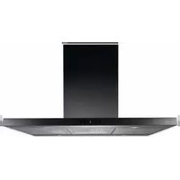
ES9192EM - Range hood Atag - Free user manual and instructions
Find the device manual for free ES9192EM Atag in PDF.


| Product type | Extractor hood |
| Brand | Atag |
| Model | ES9192EM |
| Width | 90 cm |
| Depth | 50 cm |
| Height (min-max) | 60 – 110 cm |
| Net weight | 16 kg |
| Power supply | 220-240 V, 50 Hz |
| Max power | 280 W |
| Max airflow | 650 m³/h |
| Max noise level | 65 dB(A) |
| Control type | Touch electronic |
| Number of speeds | 4 + intensive |
| Lighting | LED, 2 x 3 W |
| Filter type | Washable metal + optional charcoal |
| Filter maintenance | Dishwasher or hand wash |
| Energy class | A+ |
| Special functions | Delayed shut-off, filter saturation detection |
| Safety | Automatic shut-off in case of overheating |
| Spare parts available | Filters, LED bulbs, remote control |
| Repairability | Repairability index: 8.2/10 |
Frequently Asked Questions - ES9192EM Atag
User questions about ES9192EM Atag
0 question about this device. Answer the ones you know or ask your own.
Ask a new question about this device
Download the instructions for your Range hood in PDF format for free! Find your manual ES9192EM - Atag and take your electronic device back in hand. On this page are published all the documents necessary for the use of your device. ES9192EM by Atag.
USER MANUAL ES9192EM Atag
natural_image
Exterior view of a stainless steel kitchen air conditioner unit (no text or symbols visible)ES9111EM
ES9192EM
ES9111EX
Gebruiksaanwijzing
afzuigkappen
Mode d'emploi
hotte cheminée
Bedienungsanleitung
Dunstabzugshaube
Instructions for use
cooker hood
Anvendelse
emhætte
ATAG
NL
natural_image
Diagram of a brick wall with a ladder and directional arrows indicating movement or force (no text or symbols)
natural_image
Diagram of a vertical structure with brick wall and column, showing directional arrows indicating movement or force (no text or symbols)Bediening

BACD
natural_image
Illustration of a hand inserting a card into a rectangular device (no text or symbols visible)natural_image
Architectural cross-section diagram showing structural layers and a magnified inset of a stairwell detail (no text or labels)natural_image
Diagram of a mechanical assembly with a fan and lever, showing motion direction (no text or symbols)Lampen vervangen
natural_image
Technical line drawing of a mechanical lifting or assembly structure, showing internal components and a close-up inset (no text or symbols)
natural_image
Technical line drawing of a mechanical device with internal threading and a handle (no text or symbols)natural_image
Isometric view of a vertical cabinet with a downward arrow indicating compression or cooling (no text or symbols)natural_image
Diagram of a brick wall with a door and directional arrows indicating movement or force (no text or symbols)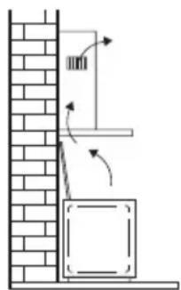

Commandes
BACD
natural_image
Diagram of a hand holding a clipboard with a curved arrow indicating motion (no text or symbols)natural_image
Architectural diagram showing structural components with an inset magnified view of a hand holding a bracket (no text or labels)natural_image
Diagram of a cooking pan with a handle and a lid, showing a lever and directional arrow (no text or symbols)
natural_image
Technical line drawing of a mechanical lifting or assembly structure, showing internal components and a close-up inset (no text or symbols)
natural_image
Technical illustration of a mechanical assembly with hands operating a component (no text or symbols visible)natural_image
Isometric view of a vertical cabinet with a downward arrow indicating compression or cooling (no text or symbols)natural_image
Diagram of a brick wall with a ladder and directional arrows indicating movement or force (no text or symbols)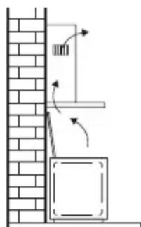

Bedienung

BACD
natural_image
Illustration of a hand inserting a card into a rectangular device (no text or symbols visible)Kohlenstofffilter

natural_image
Technical line drawing of a mechanical assembly with an inset showing a detail (no text or symbols)natural_image
Technical diagram of a mechanical assembly with a fan and lever, showing alignment and movement (no text or symbols)Lampen ersetzen
natural_image
Technical line drawing of a mechanical lifting or lifting mechanism, showing structural components and a magnified inset (no text or symbols)
natural_image
Technical illustration of a mechanical assembly with hands holding a coiled component (no text or symbols visible)natural_image
Isometric diagram of a vertical elevator with a downward arrow indicating airflow or pressure, mounted on a platform (no text or symbols)natural_image
Symbol of a trash bin with crossed x-marks and a blank base (no text or numbers)| Precautions you must take | 5 | |
| Extraction | systems |
Use
| Controls | 7 |
Maintenance
| Cleaning | 9 | ||
| Grease | filters | ||
| Carbon | filter | ||
| LED | lighting |
Installation
| General | 11 | |
| Electrical | connection | 1 |
| Mounting | 13 |
Appendix
| Disposal | 15 |
Description
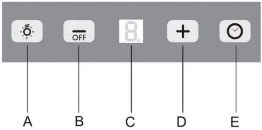
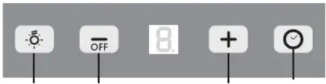
A Lighting
B Off switch
C Display chosen speed and cleaning
D Switching on the ventilator / increasing speed
E Timer
Introduction
This user manual gives you a quick overview of all the possibilities offered by the appliance. You will find information on safety measures and maintaining the appliance.
Please retain this user manual and the installation guide. They may be of use to future users of the appliance.

Precautions you must take

Make sure the appliance is installed by an authorised installer (see "Installation" chapter). Do not connect the appliance to the mains before completing the installation.
- Connect the appliance in accordance with the applicable regulations in your area.
- We advise you to wear protective work gloves during the installation of the cooker hood because of possible sharp edges.
- The appliance has been manufactured in accordance with the latest safety standards. However we do advise that persons with a mental or motor impairment do not use this appliance without the proper supervision of a competent person. The same applies to children.
- Never use the cooker hood if the grease filter has not been properly installed!
• Do not lean against the cooker hood. - Never place objects on the hood unless specifically indicated.
- Make sure there is sufficient ventilation when you use the cooker hood on a gas cooker.
- The exhaust must never be connected to a flue that is also used for other heating appliances.
- Never flambé under the cooker hood and always clean the filters promptly. Never leave frying pans unattended during use, as the heated fat may catch fire.
- The cooker hood needs to be cleaned regularly (at least once a month) on the inside as well as on the outside. Insufficient cleaning or late replacement of filters may pose a fire hazard.
- If the connection cable becomes damaged, it should be replaced by the manufacturer's service department or by a person with equivalent qualifications, in order to prevent dangerous situations from arising.
- Attention! Intensive use may cause condensation to form on the cooker hood. Condensation can be removed easily with a dry cloth.
Precautions you must take
- When replacing the lights, first disconnect the appliance from the mains! Only use identical lamps with the wattage indicated. Only use the cooker hood with lamps installed, in order to reduce the risk of electric shock.
- Accessible parts may become hot when used with cooking appliances.
- The grease filters become hot during operation. Wait a minimum of 30 minutes after cooking before cleaning the filters.
- The power must be switched off during repairs or cleaning. Remove the plug from the mains socket or turn the switch in the meter cupboard to zero.
- Grease and oil are flammable when they are overheated. Stay in the vicinity of the cooker when preparing food.
- We will not accept any responsibility for any faults, damage to the appliance, or fires resulting from non-observance of the instructions included in this manual.
Extraction systems
Depending on the type, the cooker hoods can be connected in one of two ways:
-
To a duct. The cooking vapours extracted by suction are carried outside, once the grease particles have been filtered. This is the best method.
-
Recirculation hood. When the hood is connected as a recirculation hood, the grease particles and odour in the extracted vapours are filtered.
The extracted air is not carried outside but recirculates in the kitchen. In this case you must have a carbon filter fitted.

Attention! The carbon filter needs to be ordered separately.

natural_image
Diagram of a brick wall with a ladder and directional arrows indicating movement or force (no text or symbols)
natural_image
Diagram of a brick wall with a vertical structure and directional arrows indicating movement or force (no text or symbols)Operation

BACD
Switching the extractor fan on and off
Push the OFF button B.
The extractor fan switches on at the lowest setting.
Push the OFF button B for a minimum of two seconds.
The extractor fan switches off.
Switching the lighting on and off
Push the lighting button A
The lighting switches on.
Push button A again.
The lighting switches off.
Adjusting the speed
Push the +button C.
The extractor fan switches to a higher speed. After speed 3 the extractor fan switches to the intensive setting.
Timer
Push button D.
The timer is activated. The extractor fan remains switched on at the chosen setting for 15 minutes, after which it switches off.
Push button D again.
The timer is switched off.
The timer does not work in the intensive setting!
Operation
Clean air
Push button D for 2 seconds (when switched off).
The Clean air function is activated.
The extractor fan is switched on for 10 minutes every hour. In the display this function is indicated with 2 revolving segments.
After 10 minutes the extractor fan switches off and 'C' is shown in the display.
Replacing filters
If the letter ‘F’ is shown in the display alternating with the chosen setting, the grease filters must be cleaned.
If the letter ‘A’ is shown in the display alternating with the chosen setting, the carbon filters must be replaced.
Reset the controls after replacement or cleaning of the filters.
Push the lighting button A for 5 seconds.
Letter ‘F’ or ‘A’ disappears from the display.
Cleaning

Attention! Before performing any maintenance operation, isolate the hood from the electrical supply by unplugging the appliance or switching off your household's master switch. The cooker hood should be cleaned regularly (at least as frequently as the grease filters are cleaned) both internally and externally. Do not use abrasive products.
Do not use alcohol!
Attention! Failure to comply with the basic recommendations for cleaning the cooker hood and cleaning/replacing the filters may lead to a fire. Therefore, we recommend that you observe these instructions. The manufacturer declines all responsibility for any damage to the motor or any fire damage linked to inappropriate maintenance or failure to observe the above safety recommendations.
Cooker hood
Clean the cooker hood with soapy water and a soft cloth. Then wipe with clean water to rinse. Do not apply aggressive cleaning agents such as caustic soda. The paintwork on the cooker hood will remain shiny if it is periodically rubbed with wax.

Stainless steel canopy hoods
Do not use any sort of scourer. Treat with a stainless steel care product and polish with the structure of the stainless steel.
Metal grease filters
These must be cleaned once a month (or when indicated by the filter saturation indication system, if present on your model) using non-aggressive detergents, either by hand or in the dishwasher, which must be set to a low temperature and a short cycle. The openings must be placed downwards to let the water run out of the filters. When washed in a dishwasher, aluminium grease filters may be discoloured slightly. This is normal and does not affect their filtering capacity.
Grease filters

natural_image
Illustration of a hand inserting a card into a rectangular panel with a curved arrow indicating motion (no text or symbols)Carbon filter

natural_image
Diagram showing a 3D object with a magnified inset of its interior (no text or symbols)Removing grease filters
Switch off the main Voltage! Remove the plug from the socket or turn the switch in the meter box to zero. Pull the filter towards you and tilt it down and forwards.
Replacing the carbon filter
Use a carbon filter if the extractor fan is not connected to an exhaust duct.
-
Remove the grease filters
-
Install the carbon filters
-
Install the grease filters.
Important:
- The saturation of the filter depends on the intensity of use, the cooking method and the regularity with which the grease filters are cleaned.
- The carbon filter must be replaced a minimum of every four months.
- Carbon filters cannot be washed for re-use. Saturated carbon is not environmentally friendly. Replace the filter in time.
Bulbs

natural_image
Diagram of a kitchen sink with a pan and tool, showing a valve and handle (no text or symbols)Replacing bulbs
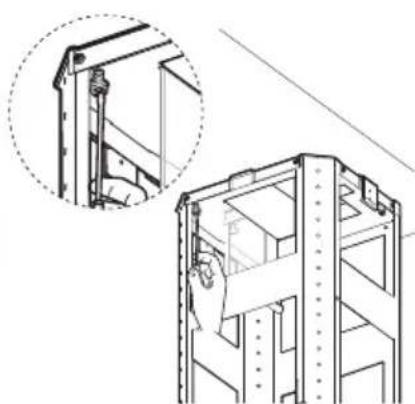
- Remove the cover from the bulb
- Replace the halogen bulb with a new bulb of a maximum of 20 Watts.
• Install the cover again.
General
This appliance must be connected to the electric mains by an authorised installer who is familiar with the safety precautions and will carry them out. The appliance is in compliance with European guidelines.
Important information:
- The distance between the lowest point of the cooker hood and a gas hob must be at least 65 cm. If using an electric, ceramic or induction hob, this distance must be at least 55 cm.
- If the cooker hood is connected to an existing exhaust duct, no other appliance must be connected to the duct (such as a hot water heater or a stove).
- Consider local regulations with respect to the ventilation of gas appliances.
- The shorter the duct, and the fewer bends in it, the better the cooker hood will work.
- Check before you start drilling that no installation pipe(s) is/are present.
- The connection pipe to the cooker hood has a diameter of 125 or 150 mm. We recommend that the exhaust pipe has as large a diameter as possible.
- The enclosed installation materials are suitable for reinforced concrete and brick walls. For some types of wall you may need special plugs and screws.
Connection
Electric connection for model: ES91..EM
The appliance has been manufactured as a class II, therefore no earth cable is necessary.
Make sure the supply voltage ratings correspond with those stated on the appliance data plate. The connection to the mains is carried out as follows:
BROWN = phase L
BLUE = phase N.
Electric connection for model: ES91..EX
This appliance is manufactured in class I, it must therefore be connected to the earth system.
- Connection to the power mains must be carried out as follows:
BROWN = Phase L
BLUE = N neutral
YELLOW/GREEN = Earth.
The neutral cable is to be connected to the clamp with symbol N while the YELLOW/GREEN cable is to be connected to the clamp next to the earthing symbol ⏻
During the electrical connection make sure that the electrical socket is equipped with earth connection.
This hood has been provided with a power plug. When installing the hood, make sure that this plug remains accessible. We recommend installing the wall socket out of view, behind the chimney cover.
Attention:
If you want to make a fixed connection, ensure that a multi-pole switch with a distance between contacts of 3 mm is installed in the supply cable.

Fitting

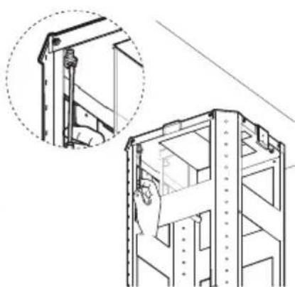
- the extractor fan from the packaging and remove the 2 screws A from the inner frame. You can now separate the inner frame from the top part.

- Hold the drilling template against the ceiling. Ensure that the arrow is on the control panel side of the extractor fan.
- Drill the connection holes with a diameter of 8 mm for fitting the inner frame B in the ceiling.
- Place suitable plugs in the drilled holes.
- Do not place a screw at position X. Do place screws in the remaining three holes. Do not tighten these screws completely.


natural_image
Technical line drawing of a multi-level building structure with an inset close-up showing internal components (no text or symbols)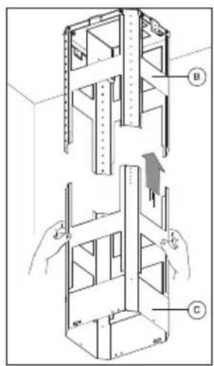
- Slide the inner frame B over the three screws.
- Make a small turning movement so that the three screws fall into the grooves.
- Fasten the fourth screw X and tighten all screws.
- Fasten the bottom part of the inner frame C to the top part B.
- Adjust the desired height.
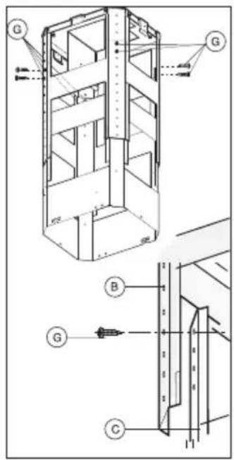
- Fasten the inner frame C with the 8 supplied screws G.

natural_image
Technical illustration of a mechanical device with a handle and internal coil (no text or symbols)- Motor version: Fasten the flexible exhaust pipe to the appropriate hole in the air exhaust.

- Recirculation version: Connect the flexible exhaust tube to the T-piece M. Screw screw P into the appropriate hole.

- Fasten the top part of the telescopic tube to the inner frame with 2 screws A.
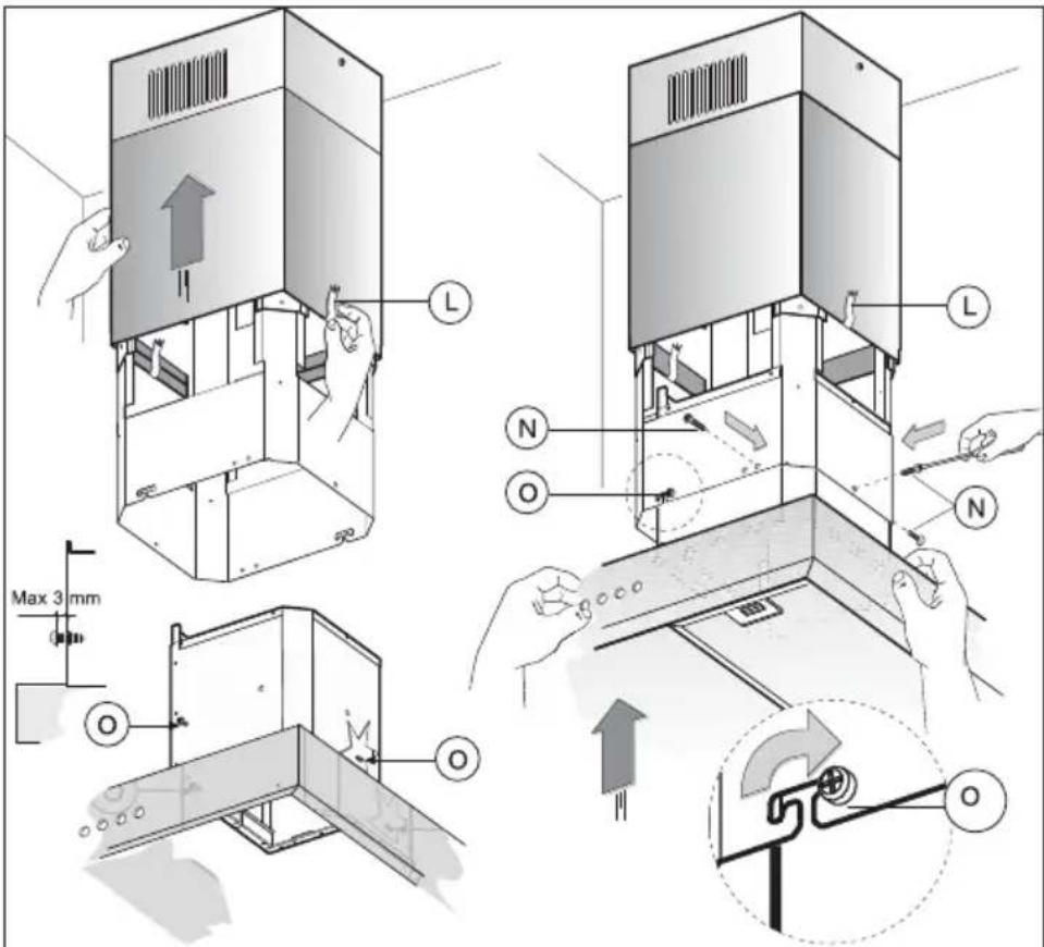
- Connect the bottom telescopic tube to the top tube. Fasten them to each other temporarily but carefully with adhesive tape L.
- Unscrew the two screws O a maximum of 3 mm.
- Fasten the housing to the bottom telescopic tube, whereby the screws O must be slid into the grooves of the bottom tube.
- Tighten the 3 supplied screws N and then the 2 screws O.

- I there is an external motor, this must be connected to the connector box depicted opposite.
- Connect the motor in accordance with the diagram in the connection box.

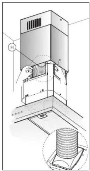
- Fasten the flexible exhaust pipe H to the flange F.

natural_image
Isometric diagram of a vertical elevator with a downward arrow indicating airflow or pressure, mounted on a platform (no text or symbols)- Remove the adhesive tape L and allow the bottom telescopic tube to slide down on to the extractor fan.
- Check that the extractor fan functions correctly.
Disposal
Disposal of appliance and packaging
This appliance was manufactured using sustainable materials. It must be disposed of responsibly at the end of its life cycle. The local authorities can provide you with the relevant information.
The packaging of this appliance is recyclable. It may have been made from:
- cardboard;
• polythene film (PE);
• CFRP-free polystyrene (PS hard foam).
You need to dispose of these materials responsibly in accordance with official regulations.

To draw attention to the fact that the segregated processing of household electrical appliances is compulsory, this appliance carries the symbol of a crossed-out dustbin. This means that you may not dispose of the appliance as household refuse at the end of its useful life. Instead, it should be taken to a special segregated refuse collection centre run by the local authority or to a dealer providing this service.
Segregated processing of household appliances prevents any negative impact on the environment and public health that might otherwise arise. It allows the recovery of the materials used to manufacture this appliance, thus generating considerable savings in terms of raw materials and energy.
CE
Declaration of conformity
We declare that our products meet the applicable European Directives, Decisions and Regulations and the requirements listed in the standards referenced.
Deres emhætte
natural_image
Diagram of a brick wall with a ladder and directional arrows indicating movement or force (no text or symbols)

Betjening

BACD
natural_image
Illustration of a hand holding a clipboard with a curved object inside (no text or symbols)natural_image
Architectural cross-section diagram showing structural layers and a magnified inset of a stair mechanism (no text or labels)natural_image
Diagram of a mechanical or electrical setup with a fan, lever, and circular component (no text or symbols)
natural_image
Technical line drawing of a multi-level building structure with an inset showing a detail view (no text or symbols)
natural_image
Technical line drawing of a mechanical device with internal threading and a handle (no text or symbols)Motorversion:
natural_image
Technical diagram of a mechanical device with a cylindrical component inserted, showing internal components and a magnified inset (no text or symbols)natural_image
Isometric view of a vertical cabinet with a downward arrow indicating compression or cooling (no text or symbols)



- ATAG
- NL
- Bediening
- Lampen vervangen
- Commandes
- Bedienung
- Kohlenstofffilter
- Lampen ersetzen
- Description
- Introduction
- Precautions you must take
- Make sure the appliance is installed by an authorised installer (see "Installation" chapter). Do not connect the appliance to the mains before completing the installation.
- Extraction systems
- Depending on the type, the cooker hoods can be connected in one of two ways:
- Operation
- Switching the extractor fan on and off
- Switching the lighting on and off
- Adjusting the speed
- Timer
- Clean air
- Replacing filters
- Cleaning
- Do not use alcohol!
- Cooker hood
- Stainless steel canopy hoods
- Metal grease filters
- Grease filters
- Carbon filter
- Removing grease filters
- Replacing the carbon filter
- Important:
- Bulbs
- Replacing bulbs
- General
- Important information:
- Connection
- Electric connection for model: ES91..EM
- Electric connection for model: ES91..EX
- Attention:
- Fitting
- Disposal
- Disposal of appliance and packaging
- Declaration of conformity
- Betjening
Brand : Atag
Model : ES9192EM
Category : Range hood