
3320-01 - Drill SKIL - Free user manual and instructions
Find the device manual for free 3320-01 SKIL in PDF.


| Product type | Corded drill |
| Brand | Skil |
| Model | 3320-01 |
| Power supply | Mains electric (220-240 V) |
| Power | 550 W |
| No-load speed | 0-2600 rpm |
| Chuck | Self-tightening chuck 10 mm (3/8") |
| Drilling capacity (steel) | 10 mm |
| Drilling capacity (wood) | 25 mm |
| Weight | 1,3 kg |
| Cable length | 2 m |
| Sound level | 86 dB(A) |
| Vibration | 3,5 m/s² |
| Main functions | Drilling, screwdriving, variable speed, forward/reverse |
| Maintenance and cleaning | Clean with a dry cloth; avoid solvents |
| Safety | Double insulation, safety trigger |
| Spare parts and repairability | Replaceable carbon brushes, interchangeable chuck |
| General information | User manual included |
Frequently Asked Questions - 3320-01 SKIL
User questions about 3320-01 SKIL
0 question about this device. Answer the ones you know or ask your own.
Ask a new question about this device
Download the instructions for your Drill in PDF format for free! Find your manual 3320-01 - SKIL and take your electronic device back in hand. On this page are published all the documents necessary for the use of your device. 3320-01 by SKIL.
USER MANUAL 3320-01 SKIL
IMPORTANT: IMPORTANT : IMPORTANTE: Read Before Using Lire avant usage Leer antes de usar

natural_image
Icon of a person reading a book inside a circle (no text or symbols)Operating/Safety Instructions Consignes d'utilisation/de sécurité Instrucciones de funcionamiento y seguridad
3320
natural_image
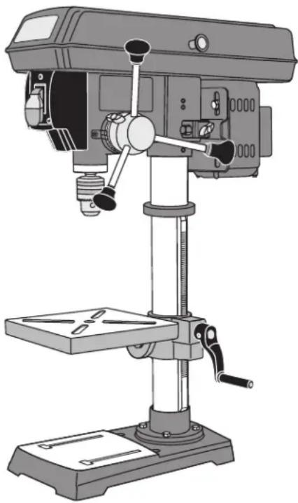
Illustration of a drill press machine with adjustable arms and base (no text or symbols)
Call Toll Free for Consumer Information & Service Locations
General Safety Rules

"READ ALL INSTRUCTIONS" Failure to follow the safety rules listed below and other basic safety precautions may result in serious personal injury.
Work Area
KEEP CHILDREN AWAY
Do not let visitors contact tool or extension cord. All visitors should be kept safe distance from work area.
KEEP WORK AREAS CLEAN
Cluttered areas and benches invite accidents.
MAKE WORKSHOP KID-PROOF
With padlocks, master switches, or by removing starter keys.
AVOID DANGEROUS ENVIRONMENTS
Don't use power tools in damp or wet locations. Keep work area well lit. Do not expose power tools to rain. Do not use the tool in the presence of flammable liquids or gases.
Personal Safety
Read and understand the owner's manual and labels affixed to the tool. Learn its application and limitations as well as the specific potential hazards peculiar to this tool.
DON'T OVERREACH
Keep proper footing and balance at all times.
STAY ALERT
Watch what you are doing. Use common sense. Do not operate tool when you are tired. Do not operate while under medication or while using alcohol or other drugs.
WEAR PROPER APPAREL
Do not wear lose clothing, gloves, neckties, rings, bracelets, or other jewelry which may get caught in moving parts. Nonslip footwear is recommended. Wear protective hair covering to contain long hair.
ALWAYS USE SAFETY GLASSES
Also use face or dust mask if cutting operation is dusty, and ear plugs during extended periods of operation. Everyday eyeglasses have only impact resistant lenses, they are NOT safety glasses.
Prevent body contact with grounded surfaces. For example: pipes, radiators, ranges, refrigerator enclosures.
DISCONNECT TOOLS FROM POWER SOURCE
When not in use, before servicing, when changing blades, bits, cutters, etc.
KEEP GUARDS IN PLACE
In working order, and in proper adjustment and alignment.
REMOVE ADJUSTING KEYS AND WRENCHES
When not in use, before servicing, when changing blades, bits, cutters, etc.
REDUCE THE RISK OF UNINTENTIONAL STARTING
Make sure the switch is in the "OFF" position before plugging in tool.
GROUND ALL TOOLS
This tool is equipped with an approved 3-conductor cord and a 3 prong grounding type plug to fit the proper grounding type receptacle. The green conductor in the cord is the grounding wire. Never connect the green wire to a live terminal.
NEVER STAND ON TOOL OR ITS STAND
Serious injury could occur if the tool is tipped or if the cutting tool is accidentally contacted. Do not store materials on or near the tool such that it is necessary to stand on the tool or its stand to reach them.
CHECK DAMAGED PARTS
Before further use of the tool, a guard or other part that is damaged should be carefully checked to ensure that it will operate properly and perform its intended function. Check for alignment of moving parts, mounting, and any other conditions that may affect its operation. A guard or other part that is damaged should be properly replaced.

All repairs, electrical or mechanical, should be attempted only by trained contact the nearest Skil Factory Service orized Service Station or other repair service.

Use only Skil replacement parts; any others may create a hazard.

The use of any other accessories not specified in the current Skil catalog, hazard
"SAVE THESE INSTRUCTIONS"
Additional Safety Rules
Tool Use
DON'T FORCE TOOL
It will do the job better and safer at the rate for which it was designed.
USE THE RIGHT TOOL
Don't force a small tool or attachment to do the job of a heavy duty tool. Don't used tool for purpose not intended—for example, don't use a circular saw for cutting tree limbs or logs.
SECURE WORK
Use clamps or a vise to hold work. It's safer than using your hand and it frees both hands to operate the tool.
NEVER LEAVE TOOL RUNNING UNATTENDED
Turn power off. Don't leave tool until it comes to a complete stop.
Tool Care
DO NOT ALTER OR MISUSE TOOL
These tools are precision built. Any alteration or modification not specified is misuse and may result in dangerous conditions.
AVOID GASEOUS AREAS
Do not operate electric tools in a gaseous or explosive atmosphere. Motors in these tools normally spark, and may result in a dangerous condition.
MAINTAIN TOOLS WITH CARE
Keep tools sharp and clean for best and safest performance. Follow instructions for lubricating and changing accessories. Inspect tool cords periodically and if damaged, have repaired by authorized service facility. Inspect extension cords periodically and replace if damaged. Keep handles dry, clean and free from oil and grease.
WARNING
Before connecting the tool to a power source (receptacle, outlet, etc.), be sure voltage supplied is the same as that specified on the nameplate of the tool. A power source with a voltage greater than that specified for the tool can result in serious injury to the user, as well as damage to the tool. If in doubt, DO NOT PLUG IN THE TOOL. Using a power source with a voltage less than the nameplate rating is harmful to the motor.
WARNING
For your own safety, do not operate your drill press until it is completely assembled and installed according to the instructions ... and until you have read and understood the following:
- Safety Rules 2-5
- Motor Specifications .... 6
- Getting To Know Your Drill Press .....9
- Assembly and Adjustments ..... 10–17
- Operation 17-19
- Maintaining Your Drill Press 20
- Troubleshooting .....20
9. STABILITY OF THE DRILL PRESS
If there is any tendency of the drill press to tilt or move during any use, bolt it to the bench top or to a piece of 3/4" exterior plywood large enough to stabilize the drill press. Bolt the plywood to the underside of the base so it extends beyond the sides of the base. DO NOT USE PRESSED WOODS PANELS. They can break unexpectedly. If the workpiece is too large to easily support with one hand, provide an auxiliary support.
10. LOCATION
Use the drill press in a well lit area and on a level surface, clean and smooth enough to reduce the risk of trips and falls. Use it where neither the operator nor the casual observer is forced to stand in line with a potential kickback.
- PROTECTION: Eyes, hands, ears and body.
WARNING
TO AVOID BEING PULLED INTO THE SPINNING TOOL—
DO NOT WEAR: Loose fitting gloves
Necktie
Loose clothing
Jewelry
DO: TIE BACK LONG HAIR
ROLL LONG SLEEVES ABOVE ELBOWS
a. If any part of your drill press is missing, mal functioning, has been damaged or broken ... such as the motor switch, or other operating control, a safety de vice or the power cord ... cease operating imme diately until the particular part is properly repaired or replaced.
b. Never place your fingers in a position where they could contact the drill bit or other cutting tool if the workpiece should unexpectedly shift or your hand should slip.
Additional Safety Rules
c. To avoid injury from parts thrown by the spring, follow the instructions exactly as given and shown in "SPINDLE RETURN SPRING" section on Page 15.
d. To prevent the workpiece from being torn from your hands, spinning on the table, shattering the tool, or being thrown, always support your work so it won't shift or bind on the tool.
- Always position "backup material" (used beneath the work piece) to contact the left side of the column.
- Whenever possible, position the workpiece to contact the left side of the column — if it is short or the table is tilted, clamp solidly to the table. Use table slots or clamping ledge around the outside edge of the table.
- When using a drill press vise, always fasten to the table.
- Never do any work “free hand” (hand holding a work - piece rather than supporting it on the table), except when polish ing.
- Securely lock head and table support to column, and table to table support before operating drill press.
- Never move the head or table support while the tool is running.
- Before starting the operation, jog the motor switch to make sure the drill bit or other cutting tool does not wobble or cause vibration.
- If a workpiece overhangs the table such that it will fall or tip if not held, clamp it to the table or provide auxiliary support.
- Use fixtures for unusual operations to adequately hold, guide and position the workpiece.
- Use the SPINDLE SPEED recommended for the specific operation and workpiece material — check the panel inside the pulley cover for drilling information; for accessories, refer to the instructions provided with the accessories.
e. Never climb on the drill press table; it could break or pull the entire drill press down on you.
f. Turn the motor switch "OFF" and unplug from power source when not in operation.
g. To avoid injury from thrown work or tool contact, DO NOT perform layout, assembly, or setup work on the table while the cutting tool is rotating.
h. Clamp workpiece or brace against column to prevent rotation.
i. Before starting, be certain chuck key is removed from chuck and that motor head and table are locked.
j. Keep pulley cover closed when not making belt adjustments.
k. Do not expose to rain or use in damp locations.
12. USE ONLY ACCESSORIES DESIGNED FOR THIS DRILL PRESS TO AVOID SERIOUS INJURY FROM THROWN, BROKEN PARTS OR WORK PIECES.
a. WHEN CUTTING LARGE DIAMETER HOLES:
Clamp the workpiece firmly to the table. Otherwise the cutter may grab and spin at high speed. Use only one-piece, cup-type, hole cutters. DO NOT use fly cutters or multi-part hole cutters as they come apart or be come unbalanced in use.
b. Drum sanders must NEVER be operated on this drill press at a speed greater than the speed rating of the drum sander.
c. Do not install or use any drill bit that exceeds 7" in length or extends 6" below the chuck jaws. They can suddenly bend outward or break.
d. Do not use wire wheels, router bits, shaper cutters, circle (fly) cutters, or rotary planers on this drill press.
e. Use recommended speed for drill accessory and workpiece material.
f. Accessories must be rated for at least the spindle speed setting of the drill press. This drill press has 5 spindle speeds. Check spindle speed setting of the drill press based on pulley speed chart located inside the pulley housing. Ensure accessories used has a higher speed rating than the current spindle speed setting of the drill press. Accessories running over its rated speed can fly apart and cause injury.
13. DIRECTION OF FEED FOR DRUM SANDING

WARNING
Feed workpiece into a sanding drum or other approved accessory, against the notation.

WARNING
A kickback occurs when workpiece suddenly binds on the cutting edge of the
tool and the workpiece is thrown by the cutter in the direction of the cutter's rotation. This can cause serious injury.
Additional Safety Rules
- NOTE AND FOLLOW THE SAFETY WARNINGS AND INSTRUCTIONS THAT APPEAR ON THE PANEL ON THE RIGHT SIDE OF THE DRILL PRESS HEAD:

- THIS DRILL PRESS HAS 5 SPEEDS: 570 RPM, 900 RPM, 1390 RPM, 2050 RPM AND 3050 RPM.
See inside of guard for specific placement of belt on pulleys.
- THINK SAFETY
SAFETY IS A COMBINATION OF OPERATOR COM - MON SENSE AND ALERTNESS AT ALL TIMES WHEN THE DRILL PRESS IS BEING USED.

WARNING
Do not allow familiarity (gained from
commonplace. Always remember that a care less fraction of a second is sufficient to inflict severe injury.

The operation of any power tool can result in foreign objects being thrown into the eyes, which can result in severe eye damage. Always wear safety goggles that comply with ANSI Z87.1 (shown on
Package) before commencing power tool operation.
WARNING
Some dust created by power sanding, sawing, grinding, drilling, and other construction activities contains chemicals known to cause cancer, birth defects or other reproductive harm. Some examples of these chemicals are:
- Lead from lead-based paints,
- Crystalline silica from bricks and cement and other masonry products, and
- Arsenic and chromium from chemically treated lumber.
Your risk from these exposures varies, depending on how often you do this type of work. To reduce your exposure to these chemicals: work in a well ventilated area, and work with approved safety equipment, such as those dust masks that are specially designed to filter out microscopic particles.
Laser safety

WARNING
To reduce the risk of injury:
- Do not stare directly at the laser beam. Eye damage may occur if you deliberately stare into the beam.
- The laser light beam used in this system is Class II with maximum 1 mW and 650 nm wavelengths. AVOID DIRECT EYE EXPOSURE.
-
The laser must be used and maintained in accordance with the manufacturer's instructions:
-
Never aim the beam at any person or an object other than the workpiece.
- Do not project the laser beam into the eyes of others.
- Always ensure the laser beam is aimed at a workpiece without reflective surfaces as the laser beam could be projected into your eyes or the eyes of others.
CAUTION
Use of controls or adjustments or performance of procedures other than those specified herein may result in hazardous radiation exposure.

Motor Specifications and Electrical Requirements
General Specifications
Voltage Rating ....120 V, 60 Hz
Amperage Rating ....3.2 A
No Load Speed ....N 1,700/min
Drilling capacity 23/8" (6 cm)
Chuck capacity .....1/16"-1/2" (1.5-13 mm)
Pulley speeds . . . (570, 900, 1390, 2050, 3050 RPM)
Table size ....7 5/8 x 7 5/8"
Motor Specifications
In the event of a malfunction or breakdown, grounding provides a path of least resistance for electric current to reduce the risk of electric shock. This tool is equipped with an electric cord having an equipment-grounding conductor and a grounding plug. The plug must be plugged into a matching outlet that is properly installed and grounded in accordance with all local codes and ordinances.
This Drill Press is designed to use a 1700 RPM motor. It is wired for operation on 110-120 volts, 60 Hz. alternating current. Before connecting the motor cord to power source, make certain the switch is in the "OFF" position and be sure the electric current is of the same characteristics as stamped on the drill press nameplate.
Connection To A Power Source
This machine must be grounded while in use to protect the operator from electric shock.
Plug power cord into a 110-120V properly grounded type outlet protected by a 15-amp dual element time delay fuse or circuit breaker.
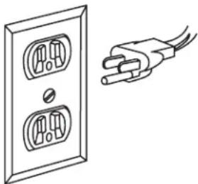
Not all outlets are properly grounded. If you are not sure that your outlet, as pictured in Fig. 1, is properly grounded; have it checked by a qualified electrician.

DANGER
To avoid electric shock, do not touch the metal prongs on the plug when installing the plug to or from the outlet.

DANGER
Failure to properly ground this power tool can cause electrocution or serious
shock, particularly when used near metal plumbing or other metal objects. If shocked, your reaction could cause your hands to hit the tool.,

WARNING
If power cord is worn, cut or damaged in any way, have it replaced immediately to fire hazard.
Your unit is for use on 120 volts; it has a plug that looks like the one in Figure 1.
FIG. 1
natural_image
Line drawing of a wall socket connected to a plug, showing electrical wiring (no text or symbols)This power tool is equipped with a 3-conductor cord and grounding type plug, approved by Underwriters Laboratories and the Canadian Standards Association. The ground conductor has a green jacket and is attached to the tool housing at one end and to the ground prong in the attachment plug at the other end.
If the outlet you are planning to use for this power tool is of the two-prong type, DO NOT REMOVE OR ALTER THE GROUNDING PRONG IN ANY MAN NER. Have a qualified electrician replace the TWO-prong outlet with a properly grounded THREE-prong outlet.
Improper connection of the equipment-grounding conductor can result in a risk of electric shock. The conductor with insulation having an outer surface that is green with or without yellow stripes is the equipment-conductor. If repair or replacement of the electric cord or plug is necessary, do not connect the equipment-grounding conductor to a live terminal.
Check with a qualified electrician or service personnel if the grounding instructions are not completely understood, or if in doubt as to whether the tool is properly grounded.
Always use proper extension cord. The use of any extension cord will cause some loss of power. To keep this to a minimum and to prevent overheating and motor burn-out, use the table below to determine the minimum wire size (A.W.G.) extension cord. Use only 3-wire extension cords which have 3-prong grounding type plugs and 3-pole receptacles which accept the tool's plug. Make sure your extension cord is in good condition.
Extension Cord Length Wire Size A.W.G.
0-25 feet 18
26-50 feet 16
51-100 feet 16
"SAVE THESE INSTRUCTIONS"
Table of Contents
General Safety Rules....2
Additional Safety Rules....3-5
Motor Specifications and Electrical Requirements....6
Table of Contents....7
Unpacking and Checking Contents ....8
Getting to Know Your Drill Press 9
Assembly and Adjustments ....10-13
Basic Drill Press Operation....17-19
Maintaining Your Drill Press....20
Troubleshooting 20
Unpacking and Checking Contents
WARNING To reduce the risk of injury, never connect plug to power source outlet until all assembly steps are complete and until you have read and understood the entire owner's manual.
Model 3320 Motorized Drill Press is shipped complete in one box.
- Unpacking and Checking Contents. Separate all parts from packing materials and check each one with the "Table of Loose Parts" to make sure all items are accounted for before discarding any packing material.
WARNING If any parts are missing, do not attempt to assemble the drill press, plug in power cord or turn the switch on until the missing parts are obtained and are installed correctly.
- Remove the protective oil that is applied to table, base and column. Use any ordinary household type grease and spot remover.
WARNING To avoid fire or toxic reaction, never use gasoline, naptha or similar highly volatile solvents.
- Apply a coat of paste wax to the table, column and machined surfaces of base to prevent rust. Wipe all parts thoroughly with a clean dry cloth.
Table of Loose Parts
ITEM DESCRIPTION QTY.
A Head Assembly 1
B "AA" Batteries 2
C Feed Handles 3
D Crank Handle 1
E Hex Head Bolts 4
F Table/Support Assembly 1
G Base 1
H Column & Flange Assembly 1
I Chuck Key 1
J Chuck 1
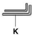
K Hex Wrench 2
L Table Support Lock Handle 1
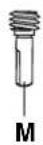
M Worm 1
N Operating Guide 1


Getting To Know Your Drill Press
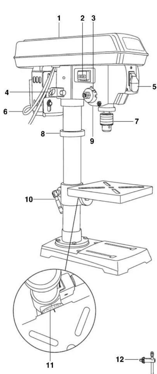

1 Pulley housing cover
2 Laser switch
3 Feed return spring and cover
4 Tension lock knob
5 On/off switch
6 Power cord
7 Chuck
8 Rack collar
9 Laser lights (2)
10 Support lock handle
11 Bevel scale
12 Chuck key
13 Belt/pulley speed chart
14 Pulley housing knob
15 Motor pulley
16 Feed handle
17 Spindle pulley
18 Depth tension knob
19 Depth scale
20 Motor
21 Quill
22 Locking screws
23 Column
24 Rack
25 Table
26 Crank handle
27 Column support
28 Base
Assembly and adjustments
WARNING To reduce the risk of injury, never connect plug to power source outlet until all assembly steps are completed.
Tools needed for assembly
- Adjustable wrench
- Phillips ^ screwdriver
• Hammer and block of wood - Ruler, level, or framing square
• Ccombination square

Base to column (Fig. 3)
- Set the base (1) on the floor.
- Place the column tube (2) on the base (1), align the column support holes with the base holes.
- Install a bolt (3) in each column support hole and tighten with the wrench.
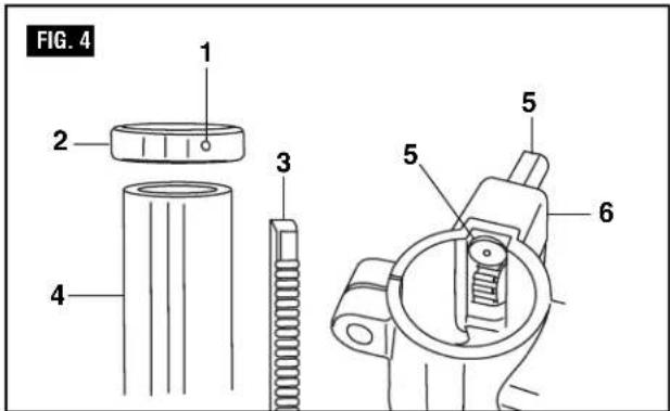
Table to column (Fig. 4–7)
- Loosen set screw (2) in column ring (1) and remove the ring.
- Remove the rack (3) from the column (4).
- Insert worm shaft (5) into the hole of the table support crank handle (6) from inside the table support. The worm shaft (5) should extend outside the housing about 1".
- Insert the rack (3) into the geared groove of the table support (6). Make sure the worm shaft (5) on the inside of the table support is engaged with the teeth of the rack. The table support should sit at the center of the rack.
- Slide the table support and rack assembly (3, 5, 6) down together onto the column. Insert the bottom edge of the rack into the lip (7) of the column support. HOLD IN THIS POSITION until step 6 is completed.
- Place the collar (1) bevel side down over the rack. Tighten the set screw (2) with the 3 mm Allen wrench to hold the rack in position.
Note: Make sure there is enough clearance to allow the table to rotate around the column. The collar must sit loosely over rack and not angled on the column. To avoid column or collar damage, only tighten the set screw enough to keep collar in place (Figure 6).


Assembly and adjustments
-
Insert the table support crank handle (9) into the worm gear shaft on the side of the table support (8). Make sure the set screw (10) is aligned on the flat of the shaft and as close to the table support as possible. Tighten the set screw (Figure 7).
-
Position the table in the same direction as the base, and tighten the column lock handle (11).
Drill press head to column (Fig. 8)
-
Lift the drill press head assembly (1) carefully and place the mounting hole of the drill press head onto the top of the column (2). Make sure the head is seated properly on the column.
-
Align the direction of the drill press head to the direction of the base and the table.
-
Tighten the two set screws (3) using an Allen wrench.
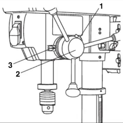
Feed handles (Fig. 9)
-
Thread the three feed handle rods (1) into the holes on the feed hub (2).
-
Hand tighten.
Note: One or two of the feed handles may be removed if an unusually-shaped workpiece interferes with handle rotation.
Laser batteries (Fig. 10)
- Turn off the laser.
- Press the tab (1) located below the laser switch (2) and lift up the laser switch cover (3).
- Insert 2 "AA" batteries in the laser battery compartment (4).
- Close the laser switch cover.
CAUTION
Remove the laser light batteries when the tool is to be stored
without use for a few days or more. If left in position, the batteries might leak and damage the laser light assembly. Damage due to leaking batteries is not covered under the warranty.
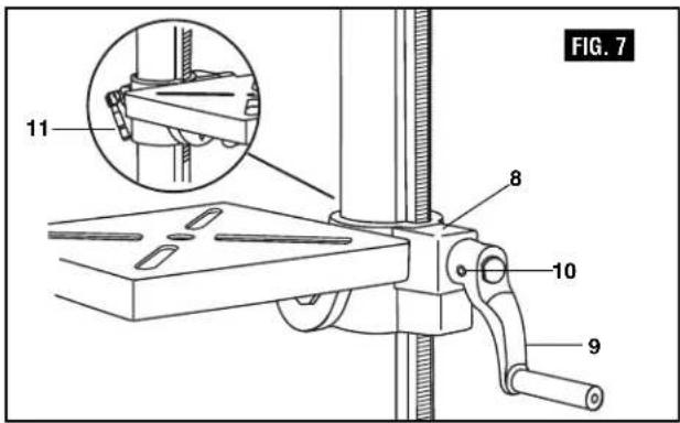
FIG. 8
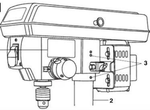
FIG. 9

FIG. 10

Assembly and adjustments
Mount the drill press (Fig. 11)
Your drill press must be securely fastened through the mounting holes (1) to a stand or work bench with heavy-duty fasteners. This will prevent the drill press from tipping over, sliding, or walking during operation.
IMPORTANT: If the stand or workbench has a tendency to move during operation, fasten it securely to the floor.
Install the chuck (Fig. 12)
- Inspect and clean the taper hole in the chuck (1) and the spindle (2). Remove all grease, coatings, and particles from the chuck and spindle surfaces with a clean cloth.
- Open the chuck jaws (3) by turning the chuck barrel clockwise by hand. Make sure the jaws are completely recessed inside the chuck.
- Seat the chuck on the spindle by placing a block of wood (4) under the chuck (1) and tapping the wood with a hammer (5) or tap the chuck with a rubber mallet.

CAUTION
To avoid damaging the chuck, make sure the jaws are completely recessed into the chuck. Do not use a metal hammer directly to drive the chuck into the spindle.
Remove the chuck (Fig. 13)
- Turn the feed handles (1) to lower the chuck (2) to the lowest position.
- Place a ball joint separator (not shown) above the chuck (3) and tap it lightly with a hammer (4) to cause the chuck to drop from the spindle.
Note: To avoid possible damage, be prepared to catch the chuck as it falls.


Operating Adjustments

WARNING
To reduce the risk of injury:
- Turn switch "OFF" and remove plug from the power source before making adjustments.
- Follow instructions carefully and wear eye protection to avoid thrown parts due to spring release.
- Never operate drill press with pulley cover open
Install the belt (Fig. 14)
- Open the pulley and belt cover (1).
- Loosen the belt tension lock knobs (2) on both sides of the drill press.
- Slide the motor (3) as close to the drill press head as possible.
- Place a belt (4) on the motor pulley (5) and the spindle pulley (6) in the proper position for the desired speed (see Fig. 17).
- Pull the motor away from the drill press head until the belt is properly tensioned. Tighten the belt tension lock knobs (2).
Note: The belt (4) should be tight enough to prevent slippage. Correct tension is set if the belt flexes about 1/2" when thumb pressure is applied at the midpoint of the belt between the pulleys.
Align the belt pulleys (Fig. 15)
- Check the alignment of the pulleys with a straight edge (1) (such as a ruler, level, or framing square) by laying the straight edge across the top of the pulleys (2).
- If the pulleys are NOT aligned, release belt tension by loosening the belt tension lock knobs (3) on both sides of the head.
- Loosen the motor mount nuts (4) with an adjustable wrench, and lower or raise the motor until the pulleys are aligned.
- Tighten the motor mount nuts (4) with an adjustable wrench to maintain the position.
- Lock the motor for the proper belt tension and tighten the tension lock knobs (3).


Spindle speeds (Fig. 16)
This drill press offers 5 spindle speeds from 570 to 3050 RPM. The highest speed is obtained when the belt is
positioned on the largest motor pulley step and the smallest spindle pulley stop.

flowchart
graph TD
    A["spindle"] --> B["5"]
    C["motor"] --> D["4"]
    E["D"] --> F["3"]
    G["C"] --> H["2"]
    I["B"] --> J["A"]
    K["A"] --> L["1"]
    M["E"] --> N["5"]
    O["D"] --> P["4"]
    Q["C"] --> R["3"]
    S["B"] --> T["A"]
    U["A"] --> V["1"]
    W["spindle"] --> X["5"]
    Y["motor"] --> Z["4"]
    AA["D"] --> AB["3"]
    AC["C"] --> AD["2"]
    AE["B"] --> AF["A"]
    AG["A"] --> AH["1"]
    AI["E"] --> AJ["5"]
    AK["D"] --> AL["4"]
    AM["C"] --> AN["3"]
    AO["B"] --> AP["A"]
    AQ["A"] --> AR["1"]
    AS["spindle"] --> AT["5"]
    AU["motor"] --> AV["4"]
    AW["C"] --> AX["3"]
    AY["B"] --> AZ["A"]
    BA["A"] --> BB["1"]
    BC["E"] --> BD["5"]
    BE["D"] --> BF["4"]
    BG["C"] --> BH["3"]
    BI["B"] --> BJ["A"]
    BK["A"] --> BL["1"]
    BM["E"] --> BN["5"]
    BO["D"] --> BP["4"]
    BQ["C"] --> BR["3"]
    BS["A"] --> BT["A"]
    BU["A"] --> BV["1"]
Assembly and adjustments

CAUTION
To reduce the risk of injury, keep pulley cover in place and in proper or when operating.
Adjust speeds and tension the belt (Fig. 17)
- Open the drill press pulley cover (1).
- Loosen the belt tension knobs (2) on both sides of the drill press head.
- Pull the motor (3) toward the drill press head.
- Set the belt on the desired steps of the motor (5) and spindle (6) pulleys according to the belt positions on the spindle speed chart (Fig. 16).
- Pull the motor away from the drill press head to increase the belt tension. Tighten the tension, knobs (2).
- The belt (4) should be tight enough to prevent slippage. Correct tension is set if the belt flexes about 1/2" (13 mm) when thumb pressure is applied at the midpoint of the belt between the pulleys.
FIG. 17

Table adjustments To raise or lower (Fig. 18).
- Raise or lower the table by loosening the column lock handle (1) and turning the crank handle (2) until the table is at the desired height.
- Tighten the table lock handle (1) before drilling.
- Rotate the table around the column by loosening the column lock handle (1) and turning the table around the column to the desired position.
- Tighten the lock handle before drilling.
To tilt the table (Fig. 19)
The table can be tilted from 0 to 45° to the left and right.
- Loosen the bevel lock bolt (1) with a wrench.
- Tilt the table (2) to the desired angle, using the bevel scale (3) as a basic guide.
- Re-tighten the bevel lock bolt (1).
- To return the table to its original position, loosen the bevel lock bolt. Realign the bevel scale (3) to the 0° setting.
- Tighten the bevel lock bolt (1) with the wrench.
FIG. 18

FIG. 19

Assembly and adjustments
To square the table to the head (Fig. 20)
- Insert a 3" (7.6 cm) drill bit (1) into the chuck (2) and tighten.
- Raise and lock the table (3) about 1" (2.5 cm) from the end of the drill bit.
- Place a combination square (4) on the table as shown. The drill bit should be parallel to the straight edge of the square.
- If an adjustment is needed, loosen the bevel lock (5) with a wrench.
- Square the table to the bit by tilting the table.
- Tighten the bevel lock bolt (5) when square.
FIG. 20

Drilling depth (Fig. 21)
- To stop the drill at a specific depth for consistent and repetitive drilling, loosen the depth scale lock (1) located on the depth scale hub (2).
- Turn the hub until the pointer (3) is aligned to the desired depth on the scale.
- Tighten the depth scale lock (1). the chuck will stop after traveling downward to the distance selected.
Note: All the necessary adjustments for the working of your drill press have been done at the factory. Please do not modify them. However, because of normal wear and tear of your tool, some readjustments might be necessary.
FIG. 21
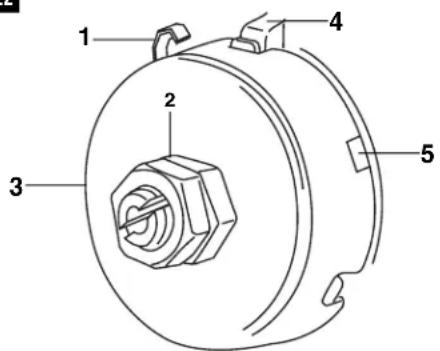
Spindle return spring (Fig. 22)
The spindle is equipped with an auto-return mechanism. The main components are a spring and a notched housing. The spring was properly adjusted at the factory and should not be readjusted unless absolutely necessary. If it needs to be adjusted, proceed as follows:
- Unplug the drill press.
- Place a screwdriver into the loop (1) to hold the spring in place.
- Loosen the two housing nuts (2) approximately 1/4" (6 mm). Do not remove the nuts from the threaded shaft.
- While firmly holding the spring housing (3), carefully pull it out until it clears the raised notch (4). Turn it until the next notch (5) is engaged with the raised notch (to increase the tension, turn it counterclockwise; to decrease the tension, turn it clockwise). Tighten the two housing nuts.
IMPORTANT! Do not overtighten the two nuts. If the nuts are tightened too much, the movement of the spindle and feed handles will be sluggish.
FIG. 22
Assembly and adjustments
Install drill bits (Fig. 23)
- Place the chuck key (1) into the side keyhole of the chuck (2), meshing the gear teeth (3).
- Turn the chuck key counterclockwise to open the chuck jaws (4).
- Insert a drill bit into the chuck far enough to obtain maximum gripping of the chuck jaws.
- Center the drill bit in the chuck jaws before final tightening of the chuck.
- Use the chuck key for the final tightening to make sure the drill bit will not slip while drilling.
WARNING To reduce the risk of injury, only use the chuck key provided with this drill press or a duplicate of it. This chuck key is self-ejecting and will "pop" out of the chuck when you let go. This action is designed to help prevent throwing of the chuck key from the chuck when power is turned "ON". Do not use any other key as a substitute; order a new one if damaged or lost.
WARNING To reduce the risk of injury, make sure the chuck key is removed from the chuck before starting any drilling operation.
FIG. 23

Assembly and adjustments

WARNING
DO NOT STARE DIRECTLY AT THE LASER BEAM! A hazard may exist if you deliberately stare into the beam. Please observe all safety rules as follows:
- The laser shall be used and maintained in accordance with the manufacturer's instructions.
- Never aim the beam at any person or an object other than the workpiece.
- Do not project the laser beam into the eyes of others.
• Always ensure the laser beam is aimed at a workpiece with out reflective surfaces as the laser beam could be projected into your eyes or the eyes of others.
Laser switch (Fig. 24)
The laser switch (1) is located on the left side of the drill press housing.
Adjust the laser line (Fig. 24 and 25)
- Place a workpiece on the table.
- Turn the laser switch (1) to the ON position.
- Lower the drill bit to meet the workpiece (2). The two laser lines should cross where the drill meets the workpiece.
- If the laser needs to be adjusted:
a. Using a 3 mm hex wrench, turn the laser adjustment hex screws (3) counterclockwise.
b. Move the laser light housing (4) until the two lines intersect where the drill meets the workpiece. DO NOT stare directly at the laser lines. - Re-tighten the adjustment hex screws (3).
Operation
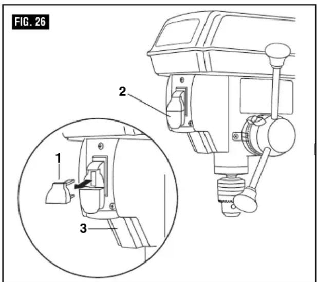
Switches (Fig. 26)
- To turn the drill press ON, insert the safety key (1) into the switch housing (2). As a safety feature, the switch cannot be turned ON without the key.
- Flip the switch upward to the ON position.
- To turn the drill press OFF, move the switch to the down position.
- To lock the switch in the OFF position, remove the safety key from the switch. Store the key in a safe place.


Operation (continued)
Position the table and workpiece (Fig. 27)
Always place a piece of backup material (1) (wood, plywood, etc.) on the table underneath the workpiece (2). This will prevent splintering on the underside of the workpiece as the drill bit breaks through. To keep the material from spinning out of control, it must contact the left side of the column as illustrated, or be clamped to the table.
Note: For small workpieces that cannot be clamped to the table, use a drill press vise (optional accessory, not included). The vise must be clamped or bolted to the table to avoid injury.
WARNING To reduce the risk of injury and the workpiece and the backup material from being torn from your hand while drilling, position them to the left side of the column. If the workpiece and the backup material are not long enough to reach the column, clamp them to the table. Failure to do this could result in personal injury.
WARNING To reduce the risk of injury, make sure the chuck key is removed from the chuck before starting any drilling operation.
Drilling a hole
Use a center punch or sharp nail to dent the workpiece where you want the hole. With the switch OFF, bring the drill bit down to the workpiece, lining it up with the hole location. Turn the switch ON and pull down on the feed handles with only enough effort to allow the drill to cut.
- Feeding too slowly might cause the drill bit to burn.
- Feeding to rapidly might stop the motor, causing the belt or drill to slip, tearing the workpiece loose, or breaking the drill bit.
- For deeper cuts, drill into the workpiece about 1/4" (6.4 mm) and raise the drill bit out of the workpiece. This will clear chips out of the hole. Drill again another 1/4" (6.4 mm) and raise the drill bit out of the hole to clear debris and chips. Repeat until finished drilling the hole.
Practice with scrap material to get the feel of the machine before attempting to do any regular drilling operation.
When drilling metal, it will be necessary to lubricate the tip of the drill with oil to prevent overheating the drill bit.
Drilling to a specific depth
Drilling a blind hole (not all the way through the workpiece) to a given depth can be done in two ways.
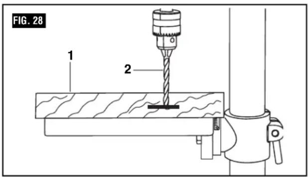
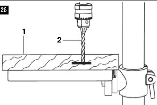
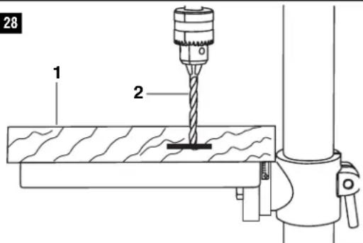
Workpiece method (Fig. 28)
- Mark the desired depth of the hole on the side of the workpiece (1).
- With the switch off, bring the drill bit (2) down until the tip is even with the mark.
- Hold the feed handle at this position.
- Lock the depth scale lock knob. The chuck and the drill bit will now be stopped at the distance selected on the depth scale.

Operation (continued)
Depth scale method (Fig. 29)
- With the switch (1) OFF, turn the feed handle (2) until the drill bit tip (3) slightly touches the top of the workpiece (4).
- Hold the feed handles in that position.
- Loosen the depth lock knob (5).
- Spin the depth scale hub (6) until the desired drilling depth is at the scale pointer.
- Lock the depth lock knob. The chuck and drill bit will now drill into the workpiece only to the distance selected on the depth scale.

General Drilling Guidelines
WARNING
To reduce the risk of injury, make sure the chuck key is removed from
the chuck before starting any drilling operation.
Drilling speeds
Important factors when determining the best drilling speed:
- Type of material
- Size of the hole to be drilled
- Type of drill bit or cutter
• Desired quality of the cut
Remember, smaller drill bits require greater speed than large drill bits. Softer materials require greater speed than harder materials.
Drilling metal
- Use metal-piercing twist drill bits.
- It is always necessary to lubricate the tip of the drill with oil to prevent overheating the drill bit.
- All metal workpieces should be clamped down securely. Any tilting, twisting, or shifting causes a rough drill hole, and increases the potential of drill bit breakage.
- Never hold a metal workpiece with your bare hands. The cutting edge of the drill bit may seize the
workpiece and throw it, causing serious injury. The drill bit will break if the metal piece suddenly hits the column.
- If the metal is flat, clamp a piece of wood under it to prevent turning. If it cannot be laid flat on the table, then it should be blocked and clamped.
Drilling wood
- Brad point bits are preferred. Metal piercing twist bits may be used on wood.
- Do not use auger bits. They turn so rapidly that they lift the workpiece off the table and whirl it around.
- Always protect the drill bit by positioning the table so the drill bit will enter the center hole when drilling through the workpiece.
- To prevent splintering, feed slowly when the bit is about to cut through to the backside of the workpiece.
- To reduce splintering and protect the point of the bit, use scrap wood as a backing or a base block under the workpiece.
Feeding the bit
- Pull down on the feed handles with only enough force to allow the drill bit to cut.
- Feeding too rapidly might stall the motor, cause the belt to slip, damage the workpiece, or break the drill bit.
- Feeding too slowly will cause the drill bit to heat up and burn the workpiece.
Maintaining Your Drill Press
Maintenance
WARNING To reduce the risk of injury, turn power switch "OFF" and remove plug from the power source outlet before maintaining or lubri cating your drill press.
Frequently blow out or vacuum sawdust or metal chips that accumulate in and on the motor, pulley housing, table, and work surface.
A coat of furniture-type paste wax applied to the table, column, and machined parts of the base will help to keep these surfaces clean.
The ball bearings in the spindle and the V-belt pulley assembly are greased and permanently sealed. Pull the spindle down and oil the spindle sleeve moderately every three months.
CAUTION Certain cleaning agents and solvents damage plastic parts. Some of these
are: gasoline, carbon tetrachloride, chlorinated cleaning solvents, ammonia and household detergents that contain ammonia. Avoiding use of these and other types of cleaning agents minimizes the probability of damage.
To avoid shock or fire hazard, if the power cord is worn, cut or damaged in any way, have it replaced immediately.
WARNING All repairs, electrical or mechanical, should be attempted only by trained
repairmen. Contact the nearest Skil Factory Service Center, Authorized Skil Service Station or other competent repair service. Use only Skil replacement parts; any other may create a hazard.
Troubleshooting
WARNING Turn switch "OFF" and always remove plug from the power source before trouble
shooting.
TROUBLE: WILL NOT START
PROBLEM 1. Power cord is not plugged in.
- Fuse or circuit breaker tripped.
- Cord damaged.
- Burned out switch.
REMEDY 1. Plug in.
- Replace fuse or reset tripped circuit breaker.
- Have cord replaced by an Authorized Skill Service Center or Service Station.
- Have switch replaced by an Authorized Skill Service Center or Service Station.
TROUBLE: DOES NOT COME UP TO SPEED
PROBLEM 1. Extension cord too light or too long.
- Low house voltage.
- Tool may not start in cold climates.
REMEDY 1. Replace with adequate cord.
- Contact your electric company.
- Tool functions best at room temperature.
natural_image
Line drawing of a wall socket connected to a power plug (no text or symbols)F Ensemble de table/support 1
G Base 1
natural_image
Simple line drawing of a folded paper or document with a label 'N' on the right page (no other text or symbols)
natural_image
Technical line drawing of a mechanical device with labeled component A (no text or symbols beyond label)


FIG. 28
PROBLÈME: NE DÉMARRE PAS
CAUSES
natural_image
Line drawing of a wall socket connected to a power plug (no text or symbols)natural_image
Simple line drawing of a rectangular object with a label 'N' and an arrow pointing upward (no text or symbols on the object itself)
natural_image
Technical line drawing of a mechanical device with labeled component A (no text or symbols beyond label)
natural_image
Technical line drawings of mechanical components (no text or symbols)



bar
FIG. 16 | RPM | buso | motor | buso | motor | |---|---|---|---|---| | 570 | E | 5 | 4 | 3 | | 570 | D | 4 | 3 | 2 | | 570 | C | 3 | 2 | 1 | | 570 | B | 2 | 1 | 1 | | 900 | E | 5 | 4 | 3 | | 900 | D | 4 | 3 | 2 | | 900 | C | 3 | 2 | 1 | | 1390 | buso | 5 | 4 | 3 | | 1390 | D | 4 | 3 | 2 | | 1390 | C | 3 | 2 | 1 | | 2050 | buso | 5 | 4 | 3 | | 2050 | D | 4 | 3 | 2 | | 2050 | C | 3 | 2 | 1 | | 3050 | buso | 5 | 4 | 3 | | 3050 | D | 4 | 3 | 2 | | 3050 | C | 3 | 2 | 1 | | 3050 | B | 2 | 1 | 1 | | 3050 | A | 1 | 1 | 1 | The chart displays a single data series for each mode at different RPM values. The x-axis represents RPM in RPM units, and the y-axis represents the count of occurrences for each mode. The legend is implicit in the color coding: black for bus, red for motor. The chart lacks explicit numerical labels but visually represents the relative proportions of each mode within the total count. The title 'FIG. 16' appears to be a figure label in the top left corner.FIG. 28
Robert Bosch Tool Corporation ("Seller") warrants to the original purchaser only, that all SKIL consumer benchtop power tools will be free from defects in material or workmanship for a period of three years from date of purchase, if original purchaser registers the product within 30 days from purchase. Product registration can be completed online at www.skil.com or by mail with the registration card included in the packaged product. Original purchasers should also retain their receipt as proof of purchase. Original purchasers that do not register their product will receive the standard Skil one year home use warranty. SKIL consumer benchtop portable power tool models will be free from defects in material or workmanship for a period of ninety days if the tool is used for professional use.
SELLER'S SOLE OBLIGATION AND YOUR EXCLUSIVE REMEDY under this Limited Warranty and, to the extent permitted by law, any warranty or condition implied by law, shall be the repair or replacement of parts, without charge, which are defective in material or workmanship and which have not been misused, carelessly handled, or misrepaired by persons other than Seller or Authorized Service Station. To make a claim under this Limited Warranty, you must return the complete product, transportation prepaid, to any SKIL Factory Service Center or Authorized Service Station. For Authorized SKIL Power Tool Service Stations, please visit www.skil.com or call 1-877-SKIL-999 (1-877-754-5999).
THIS LIMITED WARRANTY DOES NOT APPLY TO ACCESSORY ITEMS SUCH AS CIRCULAR SAW BLADES, DRILL BITS, ROUTER BITS, JIGSAW BLADES, SANDING BELTS, GRINDING WHEELS AND OTHER RELATED ITEMS.
ANY IMPLIED WARRANTIES SHALL BE LIMITED IN DURATION TO ONE YEAR FROM DATE OF PURCHASE. SOME STATES IN THE U.S., SOME CANADIAN PRO V INCESDO NOT ALLOW LIMITATIONS ON HOW LONG AN IMPLIED WARRANTY LASTS, SO THE ABOVE LIMITATION MAY NOT APPLY TO YOU.
IN NO EVENT SHALL SELLER BE LIABLE FOR ANY INCIDENTAL OR CONSEQUENTIAL DAMAGES (INCLUDING BUT NOT LIMITED TO LIABILITY FOR LOSS OF PROFITS) ARISING FROM THE SALE OR USE OF THIS PRODUCT. SOME STATES IN THE U.S. AND SOME CANADIAN PROVINCES DO NOT ALLOW THE EXCLUSION OR LIMITATION OF INCIDENTAL OR CONSEQUENTIAL DAMAGES, SO THE ABOVE LIMITATION OR EXCLUSION MAY NOT APPLY TO YOU.
THIS LIMITED WARRANTY GIVES YOU SPECIFIC LEGAL RIGHTS, AND YOU MAY ALSO HAVE OTHER RIGHTS WHICH VARY FROM STATE TO STATE IN THE U.S., PROVINCE TO PROVINCE IN CANADA AND FROM COUNTRY TO COUNTRY.
THIS LIMITED WARRANTY APPLIES ONLY TO PRODUCTS SOLD WITHIN THE UNITED STATES OF AMERICA, CANADA AND THE COMMONWEALTH OF PUERTO RICO. FOR WARRANTY COVERAGE WITHIN OTHER COUNTRIES, CONTACT YOUR LOCAL SKIL DEALER OR IMPORTER.
GARANTIE LIMITÉE DES OUTILS ÉLECTRIQUES GRAND PUBLIC SKIL DE TABLE
© Robert Bosch Tool Corporation 1800 W. Central Road Mt. Prospect, IL 60056-2230
Exportado por: Robert Bosch Tool Corporation Mt. Prospect, IL 60056-2230, E.U.A.
Importado a México por: Robert Bosch, S.A. de C.V., Calle Robert Bosch No. 405, Zona Industrial, Toluca, Edo. de México, C.P. 50070, Tel. (722) 2792300




- General Safety Rules
- Work Area
- KEEP CHILDREN AWAY
- KEEP WORK AREAS CLEAN
- MAKE WORKSHOP KID-PROOF
- AVOID DANGEROUS ENVIRONMENTS
- Personal Safety
- DON'T OVERREACH
- STAY ALERT
- WEAR PROPER APPAREL
- ALWAYS USE SAFETY GLASSES
- DISCONNECT TOOLS FROM POWER SOURCE
- KEEP GUARDS IN PLACE
- REMOVE ADJUSTING KEYS AND WRENCHES
- REDUCE THE RISK OF UNINTENTIONAL STARTING
- GROUND ALL TOOLS
- NEVER STAND ON TOOL OR ITS STAND
- CHECK DAMAGED PARTS
- "SAVE THESE INSTRUCTIONS"
- Additional Safety Rules
- Tool Use
- DON'T FORCE TOOL
- USE THE RIGHT TOOL
- SECURE WORK
- NEVER LEAVE TOOL RUNNING UNATTENDED
- Tool Care
- DO NOT ALTER OR MISUSE TOOL
- AVOID GASEOUS AREAS
- MAINTAIN TOOLS WITH CARE
- WARNING
- STABILITY OF THE DRILL PRESS
- LOCATION
- USE ONLY ACCESSORIES DESIGNED FOR THIS DRILL PRESS TO AVOID SERIOUS INJURY FROM THROWN, BROKEN PARTS OR WORK PIECES.
- a. WHEN CUTTING LARGE DIAMETER HOLES:
- DIRECTION OF FEED FOR DRUM SANDING
- Laser safety
- To reduce the risk of injury:
- CAUTION
- Motor Specifications and Electrical Requirements
- General Specifications
- Motor Specifications
- Connection To A Power Source
- DANGER
- Table of Contents
- Unpacking and Checking Contents
- Table of Loose Parts
- ITEM DESCRIPTION QTY.
- Assembly and adjustments
- Tools needed for assembly
- Base to column (Fig. 3)
- Table to column (Fig. 4–7)
- Drill press head to column (Fig. 8)
- Feed handles (Fig. 9)
- Laser batteries (Fig. 10)
- Mount the drill press (Fig. 11)
- Install the chuck (Fig. 12)
- Remove the chuck (Fig. 13)
- Operating Adjustments
- Install the belt (Fig. 14)
- Align the belt pulleys (Fig. 15)
- Spindle speeds (Fig. 16)
- Adjust speeds and tension the belt (Fig. 17)
- Table adjustments To raise or lower (Fig. 18).
- To tilt the table (Fig. 19)
- To square the table to the head (Fig. 20)
- Drilling depth (Fig. 21)
- Spindle return spring (Fig. 22)
- Install drill bits (Fig. 23)
- DO NOT STARE DIRECTLY AT THE LASER BEAM! A hazard may exist if you deliberately stare into the beam. Please observe all safety rules as follows:
- Laser switch (Fig. 24)
- Adjust the laser line (Fig. 24 and 25)
- Operation
- Switches (Fig. 26)
- Operation (continued)
- Position the table and workpiece (Fig. 27)
- Drilling a hole
- Drilling to a specific depth
- Workpiece method (Fig. 28)
- Depth scale method (Fig. 29)
- General Drilling Guidelines
- Drilling speeds
- Drilling metal
- Drilling wood
- Feeding the bit
- Maintaining Your Drill Press
- Maintenance
- Troubleshooting
- TROUBLE: WILL NOT START
- TROUBLE: DOES NOT COME UP TO SPEED
- PROBLÈME: NE DÉMARRE PAS
- CAUSES
- GARANTIE LIMITÉE DES OUTILS ÉLECTRIQUES GRAND PUBLIC SKIL DE TABLE
Brand : SKIL
Model : 3320-01
Category : Drill