
CU2200 - Security System VELLEMAN - Free user manual and instructions
Find the device manual for free CU2200 VELLEMAN in PDF.


| Product Type | Wireless Security System |
| Brand | Velleman |
| Model | CU2200 |
| Dimensions (main unit) | 150 x 100 x 30 mm |
| Weight (main unit) | 250 g |
| Power Supply | 12 V DC via mains adapter (included) |
| Power Consumption | 50 mA standby, 200 mA alarm |
| Wireless sensor range | Up to 100 m in open field |
| Number of zones | 4 programmable zones |
| Included sensors | 2 passive infrared (PIR) motion detectors |
| Built-in siren | 90 dB |
| Main features | Intrusion detection, audible alarm, auto-arm, night mode |
| Remote control | 2 RF remote controls included |
| Maintenance and cleaning | Clean sensors with a soft dry cloth. Check batteries every 6 months. |
| Safety | CE certified. Do not expose to moisture. |
| Spare parts and repairability | Sensors and remote controls available separately. Repair by an authorized professional. |
| General information | 2-year warranty. Operating temperature: -10°C to +40°C. |
Frequently Asked Questions - CU2200 VELLEMAN
User questions about CU2200 VELLEMAN
0 question about this device. Answer the ones you know or ask your own.
Ask a new question about this device
Download the instructions for your Security System in PDF format for free! Find your manual CU2200 - VELLEMAN and take your electronic device back in hand. On this page are published all the documents necessary for the use of your device. CU2200 by VELLEMAN.
USER MANUAL CU2200 VELLEMAN
To all residents of the European Union
Important environmental information about this product

This symbol on the device or the package indicates that disposal of the device after its lifecycle could harm the environment. Do not dispose of the unit (or batteries) as unsorted municipal waste; it should be taken to a specialized company for recycling. This device should be returned to your distributor or to a local recycling. Respect the local environmental rules.
If in doubt, contact your local waste disposal authorities.
Thank you for buying a VELLEMAN product! The CU2200 is equipped with a very reliable Siemens 16 bit MCU and can be used for numerous applications (except for medical and aerospace applications) such as industrial equipment or area monitoring, data capturing, home or car security... Please read the manual thoroughly before bringing this device into service. If the device was damaged in transit, don't install or use it and contact your dealer.
2. Description

Relay output jumper
1 2 3
■ ■ ■
1-2 short NC
2-3 short NO (default)
POW: 7\~12VDC power input
GND: ground
AD1/AD2: N/A
IN1, IN3, IN4, IN5, IN6, IN7, IN8, GND: 12VDC alarm input, 7\~15mA, common ground opto-coupled
IN2+, IN2-: 7\~12VDC input
OUT1: relay output, max. 1A, 24VDC, 1A, 120VAC, NC/NO (selected by jumper on board)
3. Connection

LED 1 – green status LED
Rapid flashing on/off
GSM module normal operation
Flashing on/off
GSM network connection problem
Reason:
Antenna not connected
No SIM card
Defective SIM card
Defective GSM module
LED 2 – red network LED
On
Normal
operation
Flashing on/off
Searching GSM network
Connecting to network
Receiving SMS messages
Sending SMS messages
Phone
dialling
Sound Monitoring
The CU2200 automatically picks up any phone call after eight rings. By connecting a microphone to the CU2200, you will be able to hear all actions in the room.
4. Quick Setup
- Press the yellow button so as to eject the card caddy. Insert the SIM card with the contacts facing down. Press the card back into the CU2200.
- Connect the 12VDC power supply and wait until the red LED turns on.
- Send following SMS message to the CU2200: PWD:1234,STATUS%.
- Your mobile phone will receive an SMS reply within 30 seconds reporting the health status.
NOTE: The SIM card in the CU2200 must be activated by a provider like a regular SIM card in a mobile phone. Make sure to activate the caller ID service.

natural_image
Exterior view of a device with ports and connectors, shown from multiple angles (no visible text or symbols)5. Alarm Response Time
The messenger will start the initialization after connection to the power supply. This procedure will take about 30 seconds.
In case of an alarm, the unit will send an SMS message to the control centre and to 4 pre-programmed phone numbers. The control centre can be disabled in order for the phone numbers to receive the alarm message sooner.
6. GSM Network Connectivity
- If the GSM network is suddenly inaccessible or disconnected during the SMS sending, the message will be lost.
- When the CU2200 has failed to send the message due to an inaccessible network, the unit will search for the network and keep sending the SMS when the network has been re-established.
- When failing to send SMS messages, the CU2200 will memorize up to 10 messages and send them as soon as the network is re-established.
7. SMS Command List (software version 5.0)
Configure the CU2200 through the command text sent from your mobile phone. Upon reception and processing, the unit will send a confirmation message to your mobile phone. If the command is incorrect, the unit will reply SMS format is error!
a. System Setup
- New Password Setup Command: PWD:XXXX,NEWPWD:YYYY%
XXXX Current password YYYY New password (4 digits)
Example: PWD:1234, NEWPWD:2222% Default password: 1234 New password: 2222
- Manual Health Reporting Command: PWD:XXXX,STATUS%
[SMS message received] ST:XXX;T:2005/01/28/13:00;V:XXXX;A1:0000;A2:0000;K1:X;K2:X;K3:X;K4:X;K5:X;K6:X;K7:X;K8:X;OUT1:Y;OUT2:Y;OUT3:Y;#
Example: ST:002;T:2005/01/28/13:00;V:8.15;A1:0000;A2:0000;K1:X;K2:X;K3:X;K4:1;K5:1;K6:X;K7:X;K8:X;OUT1:1;OUT2:1;OUT3:1,#
ST Unit serial number XXX ASCII code T Unit internal clock XXXX Year/month/day/time
V Operating voltage XXXX K1 Alarm channel 1 K1 \~ 8 Alarm channel 1 \~ 8 K1:0 means closed K1:1 means open
OUT1 Relay output 1 OUT1 \~ 3 Relay output 1 \~ 3 (outputs 2 and 3 are OUT1:0 means open displayed but not available) OUT1:1 means closed
- Serial Number Setup Command: PWD:XXXX,SN:YYY%
XXXX Password YYYY Serial number (0-999)
Example: PWD:1234, SN:268% Password: 1234 (default) Serial number set into the unit: 268 (default: 000)
• Control Centre Number & Health Reporting Schedule Setup
These two values are configured by one single command.
(1) The control centre number is the phone number receiving the periodic report and regular report. Besides the periodic report on schedule (command 5: power-up message), report of any command will be sent to this number in addition to the mobile phone number sending the command. Maximum 2 control centres can be defined.
Command: PWD:XXXX,CTRZ:YYYYYYYYYY,MM#%
XXXX Password
Z Control centre number (max. 2 centres)
1 means 1 ^st centre number
2 means 2^nd centre number
YYYYYYYYY Phone number in control centre
MM Period code of automatic scheduled health report
Example:
PWD:1234,CTR1:123456789,04#%
Password: 1234
Reporting health status every hour (refer to the reference table below)
(2) The periodic health report and any command from another mobile phone will be reported to the first control centre with number 123456789.
Reference table for the automatic scheduled health report
| 00 | No automatic report | 07 | Every 6 hours |
| 01 | Every 5 minutes | 08 | Every 12 hours |
| 02 | Every 15 minutes | 09 | Every day (08h00) |
| 03 | Every 30 minutes | 10 | Every odd day (08h00) |
| 04 | Every 1 hour | 11 | 1 |
| 05 | Every 2 hours | 12 | 1 |
| 06 | Every 3 hours | 13 | 1 |
| ^st , 7^th , 14^th , 21^st , 28^th day (08h00) | |
| ^st , 15^th day (08h00) | |
| ^st day of each month (08h00) |
The CU2200 automatically reports the unit's health status on a pre-defined schedule via an SMS message.
[SMS message received]
ST:XXX;T:2006/10/08/06:15;V:XXXX;A1:0000;A2:0000;K1:X;K2:X;K3:X;K4:X;K5:X;K6:X;K7:X;K8:X;OUT1:1;O
UT2:1;OUT3:1;#
ST Unit serial number XXX ASCII code
T Unit internal clock
V Operating voltage
K1 Alarm channel 1
K1:0 means closed
K1:1 means open
OUT1 Relay output 1
OUT1:0 means open
OUT1:1 means closed
Year/month/day/time
XXXX
K1 \~ 8 Alarm channel 1 \~ 8
OUT1 \~ 3 Relay output 1 \~ 3
Example:
ST:001;T:2005/01/27/12:00;V:8.14;A1:2312;A2:2131;K1:1;K2:0;K3:0;K4:1;O:1#
ST Unit serial number 001
T Unit internal clock Date: 27 Jan 2005, time: 12h00
V Operating
voltage
8.14VDC
K1 Alarm channel 1 1 Open
K2 Alarm channel 2 0 Closed
K3 Alarm channel 3 0 Closed
K4 Alarm channel 4 1 Open
O Relay output 1 1 On
- Power-Up Message
Whenever the unit is powered up, it will automatically send RESTART! to the control centre.
- System Clock Setup
Command: PWD:XXXX,TIME:AABBCDDDEE%
XXXX Password
AABBCCDDEE Year/month/day/hour/minute
Example:
PWD:1234,TIME:0602031327%
Password: 1234
Clock: 3 Feb 2006, 13h27
- Phone Number Setup
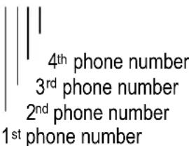
When the alarm is triggered, an SMS message is sent to following numbers:
N° 1 12345678
N° 2 36925814712
N° 3 159357456
N° 4 951753654
Example 2:
PWD:1234,ALMNU1:NUL,3:NUL#%
Password 1234
With example 1, following numbers have been cancelled:
N° 1 12345678, not made
N° 2 36925814712, retained
N° 3 159357456, not made
N° 4 951753654, retained
b. Alarm Setup
• Alarm Input Level & Alert Setup
Command: PWD:XXXX,ALMLEVELR:X,YY,ZZZZ,NNN%
XXXX Password
R Alarm channel number
X 0 means disabled
1 means closed triggers alarm
2 means open triggers alarm
3 means both closed and open triggered alarm
YY 00 means alarm not reported to control centre
10 means alarm reported to control centre 1
01 means alarm reported to control centre 2
11 means alarm reported to control centre 1 and 2
ZZZZ Selection of the alarm phone dial and alarm SMS
0 means no alarm report
1 means SMS only
2 means phone dial only
3 means SMS first, then phone dial
ZZZZ
NNN Relay output control
0 means no relay output control
1 means relay output triggered by alarm
NNN

Example 1:
PWD:1234,ALMLEVEL2:1,01,1030,100#%
Password 1234
Alarm channel 2 Once the input is closed, the alarm will be triggered
Control centre 2 will be reported by SMS
Phone number 1
Phone number 2
Phone number 3
Phone number 4
Relay output 1
Relay output 2
Relay output 3
SMS message
No report
SMS message, then phone dial
No report
Triggered
No control (not available)
No control (not available)
Example 2:
PWD:1234,ALMLEVEL1:1,11,1230,100#%
Password 1234
Alarm channel 2 Once the input is closed, the alarm will be triggered
Control centre 1 and 2 will be reported by SMS
Phone number 1
SMS message
Phone number 2
Phone dial
Phone number 3
SMS message, then phone dial
Phone number 4
No report
Relay output 1
Triggered
Relay output 2
No control (not available)
Relay output 3
No control (not available)
- SMS Alarm Message Setup
Alarm channel 1 \~ 8
Command: PWD:XXXX,ALMYTEXT:□□□□□□□□□□□#%
XXXX Password
Y Alarm channel number (1 \~ 8)
☐☐☐☐☐☐☐ SMS message (max. 100 characters – no space allowed)
Example:
PWD:1234,ALM4TEXT:DoorContact1Open#%
Password
1234
Alarm channel 4 is triggered, SMS message Door Contact 1 Open is sent to
the pre-defined phone numbers.
- SMS Message Contents
Command 8 is used to program the alarm message contents. The CU2200 will reply to the mobile phone with the programmed message for that alarm channel.
Command: PWD:XXXX,READYTEXT%
XXXX Password
Y Alarm channel number (1 \~ 8)
- Commanding the CU2200 to Send SMS Message
This command is used to make the CU2200 to send the SMS message for testing purposes.
Command: PWD:XXXX,SENDMSA:B%
XXXX Password
A Phone number (1 \~ 4)
B SMS message selection
0: schedule health check content
1\~8: alarm channel SMS message content
9: manual input message content
Example:
PWD:1234,SENDMS4:9,GoodMorning%
Password 1234
SMS message "Good Morning" will be sent to phone number 4.
Reply message: Success!: CU2200 succeeds in sending message.
Default! NONB: no preset phone number, operation failed.
Default!: Operation failed but phone number exists.
- Relay Output Control
Command: PWD:XXXX,COUTN:Y%
Password 1234
N Relay output channel (1 \~ 3) (outputs 2 and 3 not available)
| Y | 1 | Turn on (close) the output |
| 0 | Turn off (open) the output |
The relay output is N.O. by default.
Command COUTN:1 is not valid when the relay output is triggered by alarm. Reply message will be ST:XXX in this case.
In the above case, command COUTN:0 is used to reset the relay output after the alarm is triggered.
- Relay Output Delay Time
Command: PWD:XXXX,OUTNDLAY:YYYY%
XXXX Password
N Relay output channel (1 \~ 3) (outputs 2 and 3 not available)
YYYY 0000 - 9999 seconds
0000 Turn the output on or off (default)
0005 Turn on the output for 5 seconds and off again
Turn off the output for 5 seconds and on again
The relay output delay time is good for controlling e.g. an electric door lock.
- Operating Voltage Low Level Alarm Message
When the power supply voltage level is below the minimum level at 5.34VDC, the CU2200 will send an alarm SMS message.
Date 2007-06-15
Time 13:25
ST:001;TM200706121325;V:5.34#
- Operating Voltage Low Level Alarm
This command is used to set the action to be taken once the operating voltage drops below 7.0VDC. Value of the current operating voltage can be retrieved by command 2.
Command: PWD:XXXX,ADCOUT0:YY,ZZZZ,NNN%
XXXX Password
YY 00 means alarm not reported to control centre
10 means alarm reported to control centre 1
01 means alarm reported to control centre 2
11 means alarm reported to control centre 1 and 2
ZZZZ Selection of the alarm phone dial and alarm SMS
0 means no alarm report
1 means SMS only
2 means phone dial only
3 means SMS first, then phone dial
ZZZZ

NNN Relay output control
0 means no relay output control
1 means relay output triggered by alarm
NNN

- Arm/Disarm Setup
Command: PWD:XXXX,ARM%
XXXX
Password
Example:
PWD:1234,ARM%
Password
1234
Unit is armed and in alert status
Command: PWD:XXXX,DISARM%
XXXX
Password
Example:
PWD:1234,DISARM%
Password
1234
Unit is disarmed and no alarm is reported
c. System Information Report
- Default Setting
Command: PWD:1234,PARAMETER1%
ST:000;T:2006/10/01/01:01;H:1;F1:,00;F2:,00;C1:,1;C2:,1;C3:,1;C4:,1;XH:20#;
Command: PWD:1234,PARAMETER2%
ST:000;VL:7.00,O:00,0000,000;A1M:5.000,1.000,0,5.000,0.500,O:00,0000,000;A2M:5.000,1.000,0,5.000,0.00
0,O:00,0000,000;K1:1,O:00,0000,000,#;
Command: PWD:1234,PARAMETER3%
ST:000;K2:1,O:00,000,0;K3:1,O:00,000,0;K4:1,O:00,000,0;K5:1,O:00,000,0;K6:1,O:00,000,0;K7:1,O:00,000,0;K8:1,O:00,000,0;
• System Parameters RESET
Command: PWD:XXXX,PARAMETER&%
[SMS message received]
Parameter initialize success!
- Return Message
Command succeeds
SMS message: Function Code & Setting Parameters Set in the command
Command fails
SMS message: SMS Format is error!
• System Parameters Report
Command: PWD:XXXX,PARAMETER1%
[SMS message received]
ST:XXX;T:2006/10/08/08:00;H:X;F1:XXXXXXXXXX,YY;F2:XXXXXXXXXX,YY;C1XXXXXXXXXX,Y;C2:XX
XXXXXXXXXX,Y;C3:XXXXXXXXXXXX,Y;C4XXXXXXXXXXXX,Y;XH:XX#
ST: Unit serial number
T: Date/time
H:X Arm/disarm
F1 1 ^st control centre number
XXXXXXXXXX Control centre number
YY Automatic health report schedule
C1 1 ^st alarm report phone number
XXXXXXXXX Alarm report phone number
Y Alarm report enabled/disabled
XH:XX GSM network signal strength (1 \~ 31)
Command: PWD:XXXX,PARAMETER2%
About the alarm channel
[SMS message received]
ST:XXX;VL:XXXXX,O:AX,BBBB,CCC:A1M:XXXXX,XXXXX,R,WWWWW,WWWWW,O:AX,BBBB,CCC:A2M:X
XXXX,XXXXX,R,WWWWWW,WWWWWW,O:AX,BBBB,CCC;K1:N,O:AX,BBBB,CCC;#
VL Min. operating voltage (7VDC by default), alarm will be triggered if voltage drops below this level
A Alarm report to control centre 1
0 means no report
1 means report
X Alarm report to control centre 2
0 means no report
1 means report
BBBB Report status for 4 phone numbers
0 means no report
1 means SMS but no phone dial
2 means phone dial but no SMS
3 means SMS first and then phone dial
CCC Relay output control
0 means control not triggered by alarm
1 means alarm triggered control
K1:N,O:AX,BBBB,CCC refer to the alarm 1 status (see below)
Command: PWD:XXXX,PARAMETER3%
About the alarm 2 \~ 8 status
[SMS message received]
ST:XXX;K2:N,O:AX,BBBB,CCC;K3:N,O:AX,BBBB,CCC;K4:N,O:AX,BBBB,CCC;K5:N,O:AX,BBBB,CCC;K6:N,
O:AX,BBBB,CCC;K7:N,O:AX,BBBB,CCC;K8:N,O:AX,BBBB,CCC;#
K2 Alarm channel 2
N 0 means disabled
1 means closed triggered alarm
2 means open triggered alarm
3 means both closed and open triggered alarm
O Corresponding output relay status
A Alarm report to control centre 1
0 means no report
1 means report
X Alarm report to control centre 2
0 means no report
1 means report
BBBB Report status for 4 phone numbers
0 means no report
1 means SMS but no phone dial
2 means phone dial but no SMS
3 means SMS first and then phone dial
CCC Relay output control
0 means control not triggered by alarm
1 means alarm triggered control
- Manual Health Report
[SMS message received]
ST:XXX;T:2005/01/28/13:00;V:XXXX;A1:0000;A2:0000;K1:X;K2:X;K3:X;K4:X;K5:X;K6:X;K7:X;K8:X;OUT1:Y;O
UT2:Y;OUT3:Y;#
8. Technical Specifications
Electrical
Power Supply 7 \~ 12VDC
Current 500mA (SMS send/receive), 50mA (standby)
Peak Pulse Current < 2A
RS232 9 000 bps, 8 stop bits, 1 parity bit
Antenna
GSM900
RF Frequency 925 \~ 960MHz
TX Frequency 880 \~ 912MHz
RF Rating 2W, 12.5% loop loading
GSM1800
RF Frequency 1805 \~ 1880MHz
TX Frequency 1710 \~ 1785MHz
RF Rating 1W, 12.5% loop loading
Dimensions 150 x 100 x37mm
Total Weight 415g
Loading Resistance 50Ω
Radiation S/N dBi
Use this device with original accessories only. Velleman nv cannot be held responsible in the event of damage or injury resulted from (incorrect) use of this device. For more info concerning this product and the latest version of this manual, please visit our website www.velleman.eu. The information in this manual is subject to change without prior notice.
© COPYRIGHT NOTICE
The copyright to this manual is owned by Velleman nv. All worldwide rights reserved.
No part of this manual or may be copied, reproduced, translated or reduced to any electronic medium or otherwise without the prior written consent of the copyright holder.
CU2200 - DRAADLOZE SMS-ALARMMELDER
1. Inleiding
Led 2 – rode netwerkled
Aan
Normale
werking
Aan-uitknipperen
natural_image
Exterior view of a device with ports and connectors, shown from multiple angles (no visible text or symbols)[Ontvangen sms-bericht] ST:XXX;T:2005/01/28/13:00;V:XXXX;A1:0000;A2:0000;K1:X;K2:X;K3:X;K4:X;K5:X;K6:X;K7:X;K8:X;OUT1:Y;OUT2:Y;OUT3:Y;#
Voorbeeld:
ST:002;T:2005/01/28/13:00;V:8.15;A1:0000;A2:0000;K1:X;K2:X;K3:X;K4:1;K5:1;K6:X;K7:X;K8:X;OUT1:1;OUT2:1;OUT3:1;#
ST:XXX;T:2006/10/08/06:15;V:XXXX;A1:0000;A2:0000;K1:X;K2:X;K3:X;K4:X;K5:X;K6:X;K7:X;K8:X;OUT1:1;OUT2:1;OUT3:1;#
| ST | Serienummer | XXX | ASCII-code |
| T | Interne klok | XXXX | Jaar/maand/dag/uur |
| V | Voedingsspanning | XXXX | |
| K1 | Alarmkanaal 1 | K1 ~ 8 | Alarmkanaal 1 ~ 8 |
| K1:0 betekent gesloten | |||
| K1:1 betekent open | |||
| OUT1 | Relaisuitgang 1 | OUT1 ~ 3 | Relaisuitgangen 1 ~ 3 |
| OUT1:0 betekent open | |||
| OUT1:1 betekent gesloten |
Voorbeeld:
ST:001;T:2005/01/27/12:00;V:8.14;A1:2312;A2:2131;K1:1;K2:0;K3:0;K4:1;O:1#
PWD:1234,ALMNU1:NUL,3:NUL#%
Paswoord 1234
Commando: PWD:XXXX,ADCOUT0:YY,ZZZ,NNN%
XXXX Paswoord
ST:000;T:2006/10/01/01:01;H:1;F1:,00;F2:,00;C1:,1;C2:,1;C3:,1;C4:,1;XH:20#;
Commando: PWD:1234,PARAMETER2%
ST:000;VL:7.00,O:00,0000,000;A1M:5.000,1.000,0,5.000,0.500,O:00,0000,000;A2M:5.000,1.000,0,5.000,0.00
0,O:00,0000,000;K1:1,O:00,0000,000,#;
Commando: PWD:1234,PARAMETER3%
ST:000;K2:1,O:00,000,0;K3:1,O:00,000,0;K4:1,O:00,000,0;K5:1,O:00,000,0;K6:1,O:00,000,0;K7:1,O:00,000,0;K8:1,O:00,000,0;
- Resetten van de parameters
Commando: PWD:XXXX,PARAMETER&%
[Ontvangen sms-bericht]
Parameter initialize success!
- Antwoordbericht
Commando succesvol
Sms-bericht: Function Code & Setting Parameters Set in the command
Commando gefaald
Sms-bericht: SMS Format is error!
- Rapport systeemparameters
Commando: PWD:XXXX,PARAMETER1%
[Ontvangen sms-bericht]
ST:XXX;T:2006/10/08/08:00;H:X;F1:XXXXXXXXXX,YY;F2:XXXXXXXXXX,YY;C1XXXXXXXXXX,Y;C2:XX
XXXXXXXXXX,Y;C3:XXXXXXXXXXXX,Y;C4XXXXXXXXXXXX,Y;XH:XX#
ST: Serienummer
T: Datum/tijd
H:X In-/uitschakelen
O Corresponding output relay status
ST:XXX;T:2005/01/28/13:00;V:XXXX;A1:0000;A2:0000;K1:X;K2:X;K3:X;K4:X;K5:X;K6:X;K7:X;K8:X;OUT1:Y;O
UT2:Y;OUT3:Y;#
8. Technische specificaties
Elektrisch circuit
Voeding 7 \~ 12VDC
Stroom 500mA (sms
Piekimpulsstroom < 2A
natural_image
Three-panel photo showing a device with ports and connectors, no visible text or symbols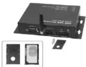
natural_image
Electronic device with ports and connectors, shown in two views (no visible text or symbols)[Message reçu] ST:XXX;T:2005/01/28/13:00;V:XXXX;A1:0000;A2:0000;K1:X;K2:X;K3:X;K4:X;K5:X;K6:X;K7:X;K8:X;OUT1:Y;OUT2:Y;OUT3:Y;#
Exemple :
ST:002;T:2005/01/28/13:00;V:8.15;A1:0000;A2:0000;K1:X;K2:X;K3:X;K4:1;K5:1;K6:X;K7:X;K8:X;OUT1:1;OUT2:1;OUT3:1,#
ST:XXX;T:2006/10/08/06:15;V:XXXX;A1:0000;A2:0000;K1:X;K2:X;K3:X;K4:X;K5:X;K6:X;K7:X;K8:X;OUT1:1;O UT2:1;OUT3:1;#
ST Numéro de série
T Horloge interne
V Operating voltage
K1 Canal d'alarme 1
K1:0 signifie ouvert
K1:1 signifie fermé
OUT1 Sortie relais 1
OUT1:0 signifie ouvert
PWD:1234,ALMNU1:NUL,3:NUL#%
Mot de passe 1234
Commande : PWD:XXXX,ALMLEVELR:X,YY,ZZZZ,NNN%
XXXX Mot de passe
ST:000;T:2006/10/01/01:01;H:1;F1:,00;F2:,00;C1:,1;C2:,1;C3:,1;C4:,1;XH:20#;
Commande : PWD:1234,PARAMETER2%
ST:000;VL:7.00,O:00,0000,000;A1M:5.000,1.000,0,5.000,0.500,O:00,0000,000;A2M:5.000,1.000,0,5.000,0.00
0,O:00,0000,000;K1:1,O:00,0000,000,#;
Commande : PWD:1234,PARAMETER3%
ST:000;K2:1,O:00,000,0;K3:1,O:00,000,0;K4:1,O:00,000,0;K5:1,O:00,000,0;K6:1,O:00,000,0;K7:1,O:00,000,0;K8:1,O:00,000,0;
ST:XXX;T:2006/10/08/08:00;H:X;F1:XXXXXXXXXXXX,YY;F2:XXXXXXXXXXXX,YY;C1XXXXXXXXXXXX,Y;C2:XX
XXXXXXXXXX,Y;C3:XXXXXXXXXXXX,Y;C4XXXXXXXXXXXX,Y;XH:XX#
ST: Numéro de série
T: Date/heure
H:X Armement/désarmement
ST:XXX;VL:XXXXX,O:AX,BBBB,CCC:A1M:XXXXX,XXXXX,R,WWWWW,WWWWW,O:AX,BBBB,CCC;A2M:X
XXXX,XXXXX,R,WWWWW,WWWWW,O:AX,BBBB,CCC;K1:N,O:AX,BBBB,CCC;#
ST:XXX;T:2005/01/28/13:00;V:XXXX;A1:0000;A2:0000;K1:X;K2:X;K3:X;K4:X;K5:X;K6:X;K7:X;K8:X;OUT1:Y;O
UT2:Y;OUT3:Y;#
Dimensions 150 x 100 x37mm
Poids 415g
Résistance 50Ω
Radiation S/B dBi
AD1/AD2: no applicable
Cable de puente de la salida relé
1 2 3
■ ■ ■
Cortocircuito entre 1-2: NC
Cortocircuito entre 2-3: NA (por defecto)
natural_image
Three-panel photo showing a device with ports and connectors, no visible text or symbols
natural_image
Electronic device with ports and a small inset showing two components (no visible text or symbols)ST:XXX;T:2006/10/08/06:15;V:XXXX;A1:0000;A2:0000;K1:X;K2:X;K3:X;K4:X;K5:X;K6:X;K7:X;K8:X;OUT1:1;OUT2:1;OUT3:1;#
ST Número de serie
T Reloj interno
PWD:1234,ALMNU1:NUL,3:NUL#%
Contraseña 1234
ST:000;T:2006/10/01/01:01;H:1;F1:,00;F2:,00;C1:,1;C2:,1;C3:,1;C4:,1;XH:20#;
Mando: PWD:1234,PARAMETER2%
ST:000;VL:7.00,O:00,0000,000;A1M:5.000,1.000,0,5.000,0.500,O:00,0000,000;A2M:5.000,1.000,0,5.000,0.00
0,O:00,0000,000;K1:1,O:00,0000,000,#;
Mando: PWD:1234,PARAMETER3%
ST:000;K2:1,O:00,000,0;K3:1,O:00,000,0;K4:1,O:00,000,0;K5:1,O:00,000,0;K6:1,O:00,000,0;K7:1,O:00,000,0;K8:1,O:00,000,0;
ST:XXX;T:2006/10/08/08:00;H:X;F1:XXXXXXXXXXXX,YY;F2:XXXXXXXXXXXX,YY;C1XXXXXXXXXXXX,Y;C2:XX
XXXXXXXXXX,Y;C3:XXXXXXXXXXXX,Y;C4XXXXXXXXXXXX,Y;XH:XX#
ST: Número de serie
T: Fecha/hora
ST:XXX;T:2005/01/28/13:00;V:XXXX;A1:0000;A2:0000;K1:X;K2:X;K3:X;K4:X;K5:X;K6:X;K7:X;K8:X;OUT1:Y;O
UT2:Y;OUT3:Y;#
8. Especificaciones
Circuito eléctrico
Valor RF 2W, 12.5% bucle
GSM1800
Valor RF 1W, 12.5% bucle
Dimensiones 150 x 100 x37mm
Peso 415g
Resistencia 50Ω
Radiación S/B dBi
(envío/recepción SMS), 50mA (standby)
natural_image
Exterior view of a device with ports and connectors, shown from multiple angles (no visible text or symbols)[Empfangene Kurzmitteilung] ST:XXX;T:2005/01/28/13:00;V:XXXX;A1:0000;A2:0000;K1:X;K2:X;K3:X;K4:X;K5:X;K6:X;K7:X;K8:X;OUT1:Y;OUT2:Y;OUT3:Y;#
Beispiel:
ST:002;T:2005/01/28/13:00;V:8.15;A1:0000;A2:0000;K1:X;K2:X;K3:X;K4:1;K5:1;K6:X;K7:X;K8:X;OUT1:1;OUT2:1;OUT3:1;#
ST:XXX;T:2006/10/08/06:15;V:XXXX;A1:0000;A2:0000;K1:X;K2:X;K3:X;K4:X;K5:X;K6:X;K7:X;K8:X;OUT1:1;OUT2:1;OUT3:1;#
PWD:1234,ALMNU1:NUL,3:NUL#%
Passwort 1234
ST:000;T:2006/10/01/01:01;H:1;F1:,00;F2:,00;C1:,1;C2:,1;C3:,1;C4:,1;XH:20#;
ST:000;VL:7.00,O:00,0000,000;A1M:5.000,1.000,0,5.000,0.500,O:00,0000,000;A2M:5.000,1.000,0,5.000,0.00
0,O:00,0000,000;K1:1,O:00,0000,000,#;
ST:XXX;T:2006/10/08/08:00;H:X;F1:XXXXXXXXXXXX,YY;F2:XXXXXXXXXXXX,YY;C1XXXXXXXXXXXX,Y;C2:XX
XXXXXXXXXX,Y;C3:XXXXXXXXXXXX,Y;C4XXXXXXXXXXXX,Y;XH:XX#
ST: Seriennummer
T: Datum/Zeit
ST:XXX;T:2005/01/28/13:00;V:XXXX;A1:0000;A2:0000;K1:X;K2:X;K3:X;K4:X;K5:X;K6:X;K7:X;K8:X;OUT1:Y;O
UT2:Y;OUT3:Y;#
8. Technische Daten
Elektrischer Kreis
RF-Wert 2W, 12.5% Schleife (loop loading)
GSM1800
RF-Frequenz 1805 \~ 1880MHz
TX-Frequenz 1710 \~ 1785MHz
RF-Wert 1W, 12.5% Schleife (loop loading)
Abmessungen 150 x 100 x37mm
Gewicht 415g
Widerstand 50Ω
Abstrahlung S/R dBi
Velleman® Service and Quality Warranty
Velleman ^® has over 35 years of experience in the electronics world and distributes its products in more than 85 countries.
All our products fulfil strict quality requirements and legal stipulations in the EU. In order to ensure the quality, our products regularly go through an extra quality check, both by an internal quality department and by specialized external organisations. If, all precautionary measures notwithstanding, problems should occur, please make appeal to our warranty (see guarantee conditions).
General Warranty Conditions Concerning Consumer Products (for EU):
- All consumer products are subject to a 24-month warranty on production flaws and defective material as from the original date of purchase.
- Velleman ^3 can decide to replace an article with an equivalent article, or to refund the retail value totally or partially when the complaint is valid and a free repair or replacement of the article is impossible, or if the expenses are out of proportion.
You will be delivered a replacing article or a refund at the value of 100% of the purchase price in case of a flaw occurred in the first year after the date of purchase and delivery, or a replacing article at 50% of the purchase price or a refund at the value of 50% of the retail value in case of a flaw occurred in the second year after the date of purchase and delivery.
• Not covered by warranty:
- all direct or indirect damage caused after delivery to the article (e.g. by oxidation, shocks, falls, dust, dirt, humidity...), and by the article, as well as its contents (e.g. data loss), compensation for loss of profits;
- frequently replaced consumable goods, parts or accessories such as batteries, lamps, rubber parts, drive belts... (unlimited list);
- flaws resulting from fire, water damage, lightning, accident, natural disaster, etc.;
- flaws caused deliberately, negligently or resulting from improper handling, negligent maintenance, abusive use or use contrary to the manufacturer's instructions;
- damage caused by a commercial, professional or collective use of the article (the warranty validity will be reduced to six (6) months when the article is used professionally);
- damage resulting from an inappropriate packing and shipping of the article; - all damage caused by modification, repair or alteration performed by a third party without written permission by Velleman®.
- Articles to be repaired must be delivered to your Velleman ^ dealer, solidly packed (preferably in the original packaging), and be completed with the original receipt of purchase and a clear flaw description.
- Hint: In order to save on cost and time, please reread the manual and check if the flaw is caused by obvious causes prior to presenting the article for repair. Note that returning a non-defective article can also involve handling costs.
- Repairs occurring after warranty expiration are subject to shipping costs. - The above conditions are without prejudice to all commercial warranties.
The above enumeration is subject to modification according to the article (see article's manual).
NL

- To all residents of the European Union
- Important environmental information about this product
- Description
- Connection
- Sound Monitoring
- Quick Setup
- Alarm Response Time
- GSM Network Connectivity
- SMS Command List (software version 5.0)
- a. System Setup
- • Control Centre Number & Health Reporting Schedule Setup
- Command: PWD:XXXX,CTRZ:YYYYYYYYYY,MM#%
- b. Alarm Setup
- • Alarm Input Level & Alert Setup
- c. System Information Report
- • System Parameters RESET
- - Return Message
- • System Parameters Report
- Command: PWD:XXXX,PARAMETER2%
- Command: PWD:XXXX,PARAMETER3%
- Technical Specifications
- © COPYRIGHT NOTICE
- CU2200 - DRAADLOZE SMS-ALARMMELDER
- Inleiding
- Commando: PWD:XXXX,ADCOUT0:YY,ZZZ,NNN%
- - Resetten van de parameters
- - Antwoordbericht
- - Rapport systeemparameters
- Technische specificaties
- Especificaciones
- Technische Daten
- Velleman® Service and Quality Warranty
- General Warranty Conditions Concerning Consumer Products (for EU):
- • Not covered by warranty:
- NL
Brand : VELLEMAN
Model : CU2200
Category : Security System