
WorkFit 45-405-026 - Flat screen mount Ergotron - Free user manual and instructions
Find the device manual for free WorkFit 45-405-026 Ergotron in PDF.


| Product Type | Flat Panel Mount |
| Brand | Ergotron |
| Model | WorkFit 45-405-026 |
| Dimensions (H x W x D) | 24 x 18 x 6 inches (approx.) |
| Weight | 20 lbs |
| Material | Steel, aluminum |
| Color | Black |
| VESA Compatibility | 75x75, 100x100, 200x100, 200x200 mm |
| Weight Capacity | Up to 30 lbs (13.6 kg) |
| Screen Size Compatibility | 17" to 32" |
| Adjustment | Height, tilt, swivel, rotation |
| Tilt Range | -5° to +15° |
| Swivel Range | ±90° |
| Rotation | 360° |
| Height Adjustment | 14" range (35.6 cm) |
| Power Supply | None (manual operation) |
| Mounting Type | Desk clamp or grommet mount |
| Desk Thickness Range | 0.5" to 2.75" (1.3 to 7 cm) |
| Maintenance | Clean with a damp cloth; do not use solvents |
| Safety | Mount to solid surface; do not exceed weight limit |
| Spare Parts Availability | Contact Ergotron or authorized dealers |
Frequently Asked Questions - WorkFit 45-405-026 Ergotron
User questions about WorkFit 45-405-026 Ergotron
0 question about this device. Answer the ones you know or ask your own.
Ask a new question about this device
Download the instructions for your Flat screen mount in PDF format for free! Find your manual WorkFit 45-405-026 - Ergotron and take your electronic device back in hand. On this page are published all the documents necessary for the use of your device. WorkFit 45-405-026 by Ergotron.
USER MANUAL WorkFit 45-405-026 Ergotron
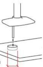
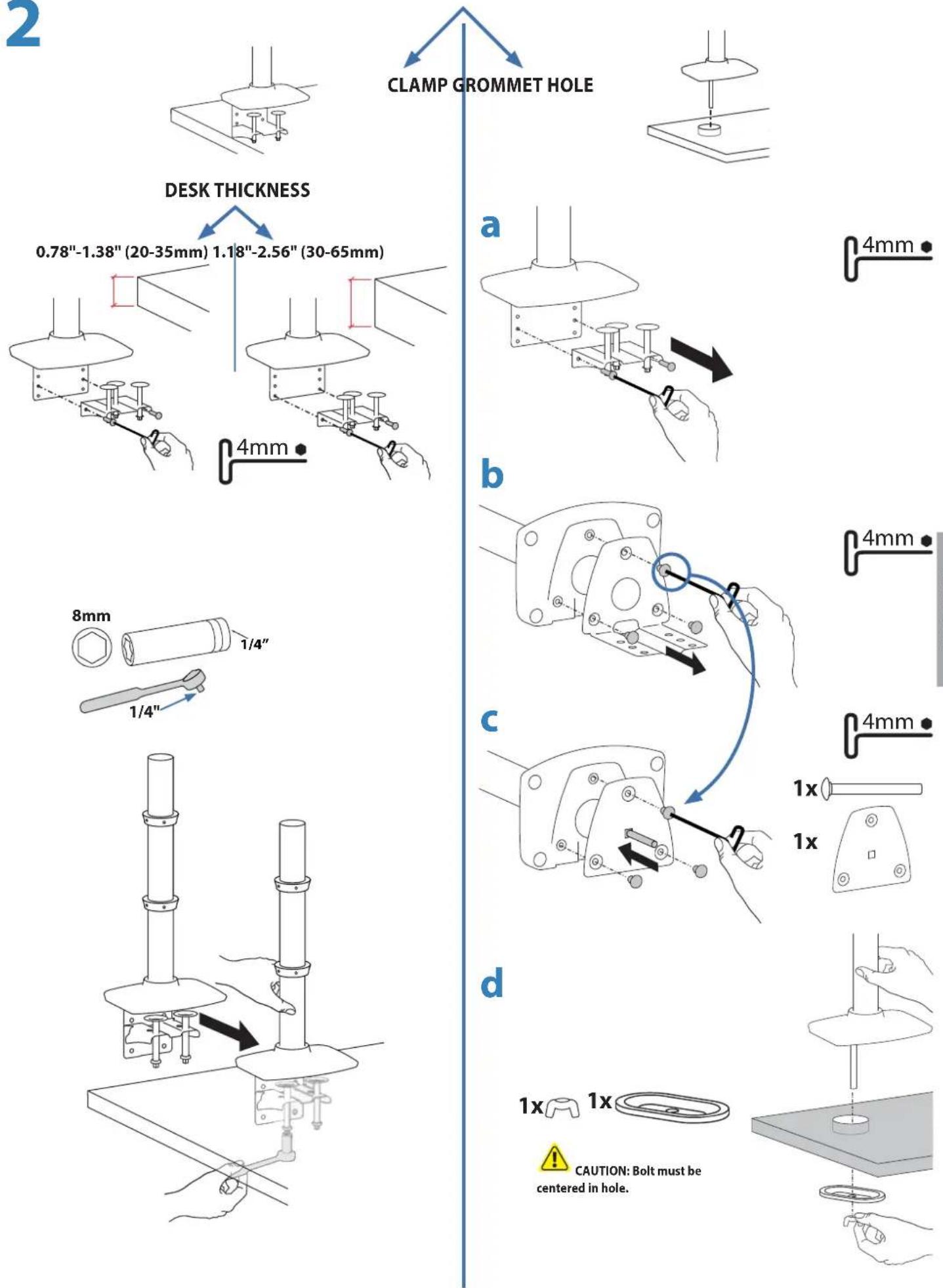
CLAMP GROMMET HOLE
0.78"-2.56"
(20-65mm)
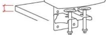
natural_image
Pure mechanical assembly diagram showing two vertical rods mounted on a bracket (no text or symbols)0.78"-2.25"(20-57mm)
0.5"-2.5" (13-64mm)
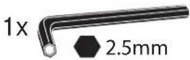
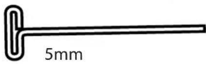
Tools Needed

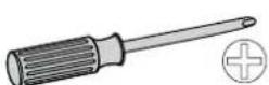
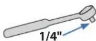
For the latest User Installation Guide please visit: www.ergotron.com

User's Guide - English
Features & Specifications
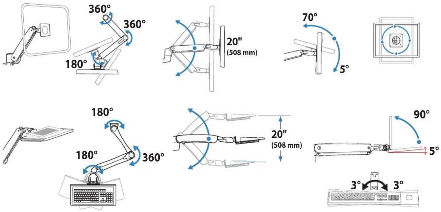
Safety

CAUTION: DO NOT rotate monitor past rear edge of desk. Doing so will create an unstable situation and may cause equipment damage or personal injury.

CAUTION: Monitor may hit Keyboard arm in some configurations. Use caution when moving your monitor and keyboard arms.
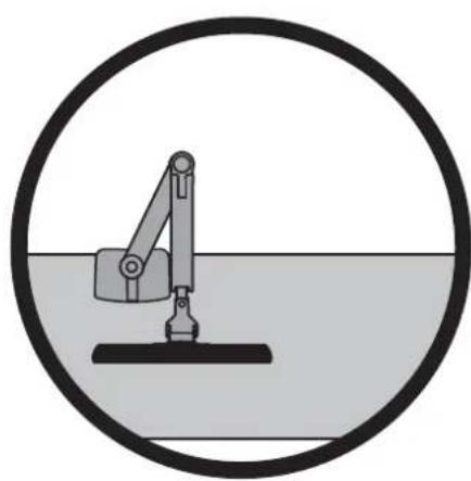
natural_image
Simple line drawing of a mechanical device inside a circle (no text or symbols)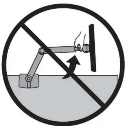
natural_image
Prohibition sign showing a robotic arm without force, crossed out by a diagonal line (no text or symbols)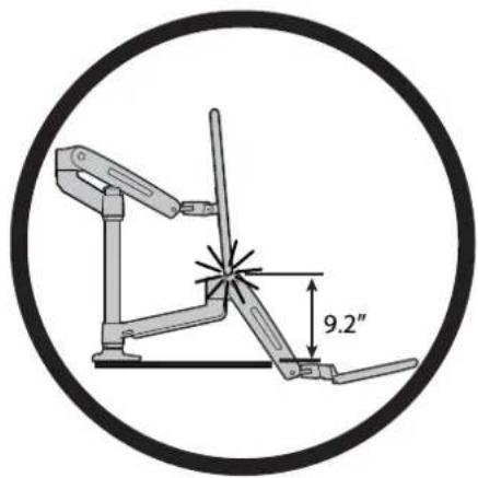

Important! You will need to adjust this product after installation is complete. Make sure all your equipment is properly installed on the product before attempting adjustments. This product should move smoothly and easily through the full range of motion and stay where you set it. If movements are too easy or difficult or if product does not stay in desired positions, follow the adjustment instructions to create smooth and easy movements. Depending on your product and the adjustment, it may take many turns to notice a difference. Any time equipment is added or removed from this product, resulting in a change in the weight of the mounted load, you should repeat these adjustment steps to ensure safe and optimum operation.
Components

| A | B | C | |||
| 1 | 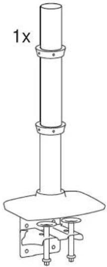 | 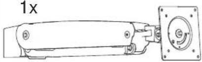 |  | 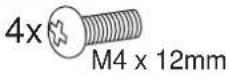 | |
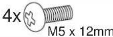 | |||||
| 2 | 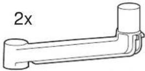 | 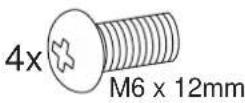 | |||
| 3 | 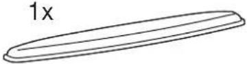 | 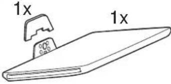 | 1x M3 x 6mm | ||
| 4x M4 x 10mm | |||||
| 4 | 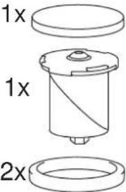 | 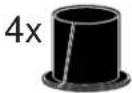 | 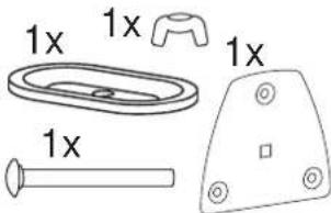 | 4x 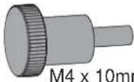 n n | |
| 4x | 4x M5 x 7mm | ||||
| 5 | 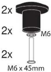 | 2x | 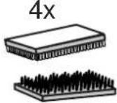 | 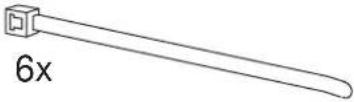 | 4x 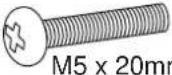 n n |
 | 4x 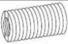 M8M5 Converter M8M5 Converter | ||||
| 6 | 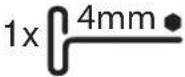 | 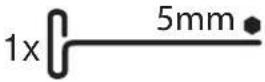 | 1x 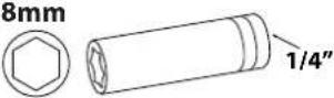 | 4x 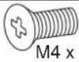 8mm 8mm | |
2x 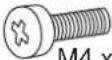 WTA 14mm WTA 14mm | |||||
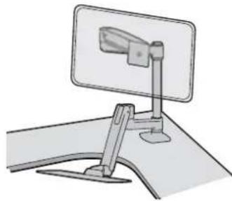
1 Desk Placement
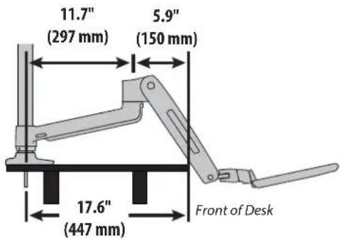
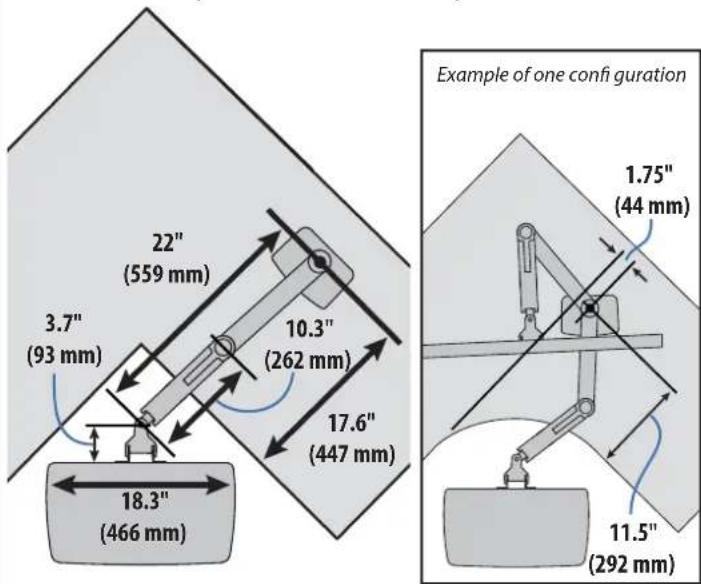
Maximum dimensions to allow keyboard arm to lower below front of desk.

CAUTION: Base must be completely on desk surface. Failure to follow these instructions may result in equipment damage or personal injury.
natural_image
Illustration of a desktop desk with a stand and monitor (no text or symbols)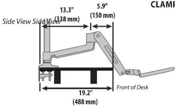
CLAMP GROMNET HOLE
Top View Top View
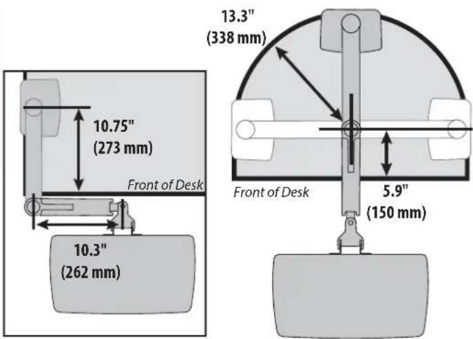
Grommet hole can be located anywhere along this arch.
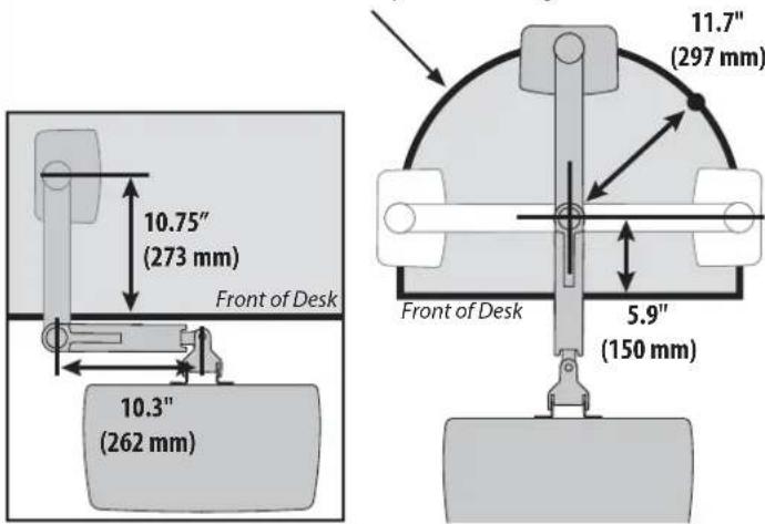
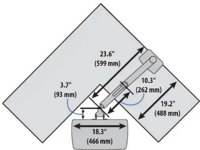
Corner mount - Top View Corner mount - Top View
888-45-323-G-00 rev.A • 03/14
2
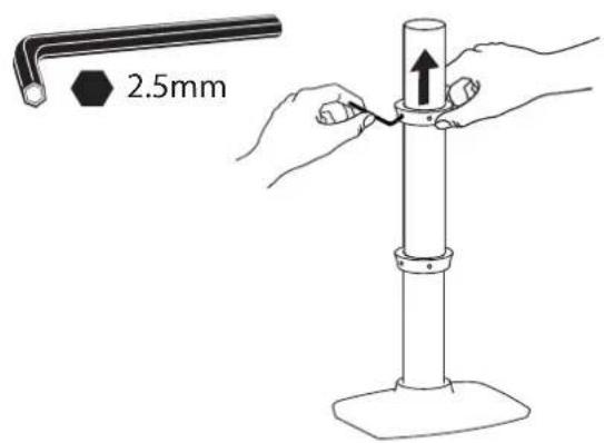
3 Mount extension and arm to pole.
a
b
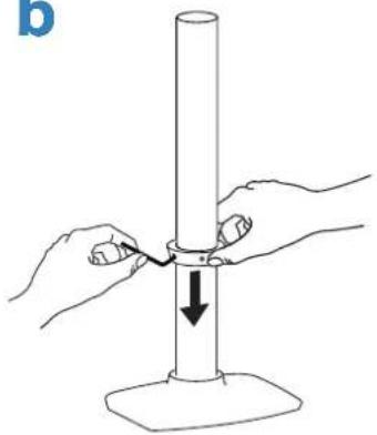
natural_image
Illustration of hands holding a cylindrical object with a downward arrow indicating force or movement (no text or symbols)C
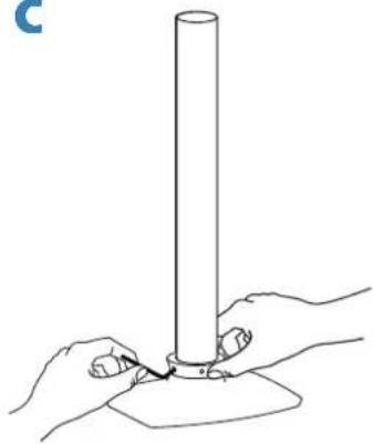
natural_image
Line drawing of two hands holding a cylindrical object with a base, no text or symbols present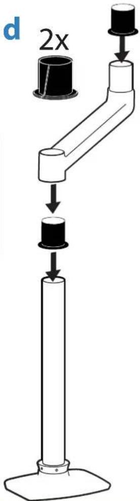
e
f
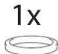
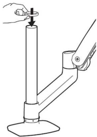
natural_image
Line drawing of a hand using a tool to lift a cylindrical mechanical component (no text or symbols)4
a
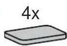
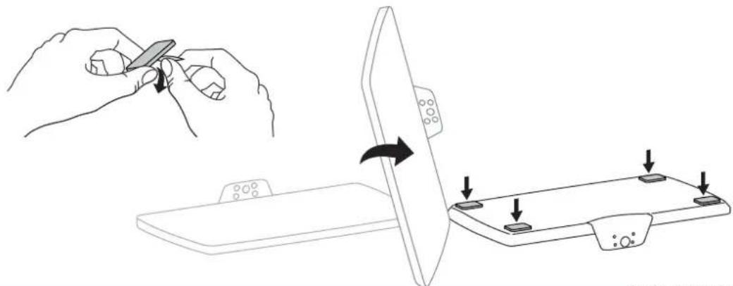
natural_image
Illustration showing a hand holding a tool interacting with a device, and a close-up of the device being adjusted (no text or symbols present)b
C
natural_image
Line drawing of a hand using a tool to press or adjust a component on a flat surface (no text or symbols)5
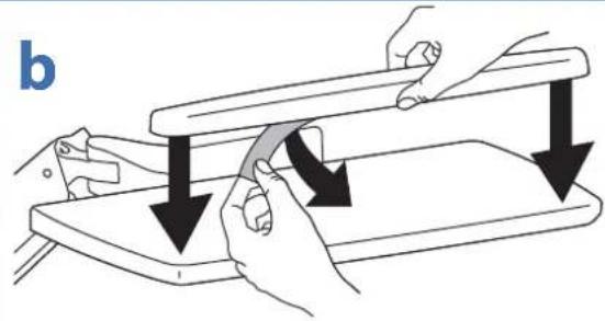
natural_image
Illustration of hands using a tool to lift a flat plate, showing motion arrows (no text or symbols)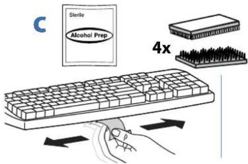
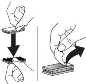
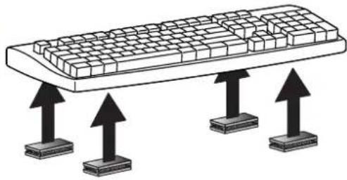
natural_image
Illustration of a computer keyboard with three upward arrows pointing to its base (no text or symbols)d
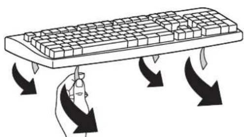
natural_image
Illustration of a hand pressing down on a keyboard with curved arrows indicating press or move (no text or symbols)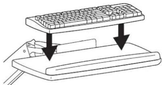
natural_image
Diagram of a computer keyboard being inserted into a slide, showing two downward arrows indicating compression or disassembly (no text or symbols present)
Portrait / Landscape Options
OPTION i If you want full portrait/landscape rotation, skip to step 8 on the next page.
OPTION ii If you do not want your TV/Monitor to rotate all all, you can stop rotation by inserting the set screw.

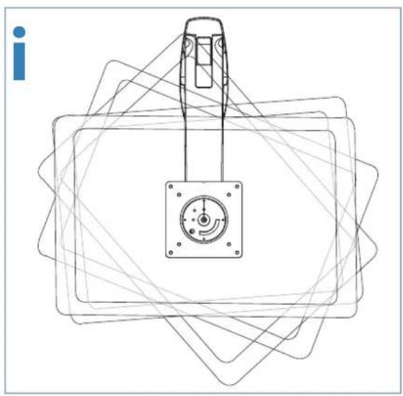
natural_image
Pure technical line drawing of a mechanical component with no text, numbers, or symbols
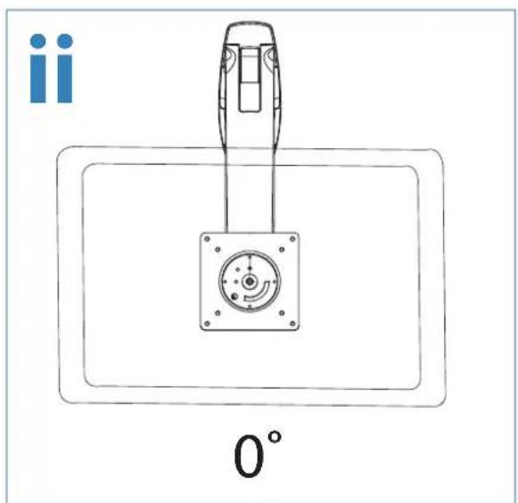
natural_image
Technical line drawing of a mechanical component with a 0° angle标注 (no text or symbols on the diagram itself)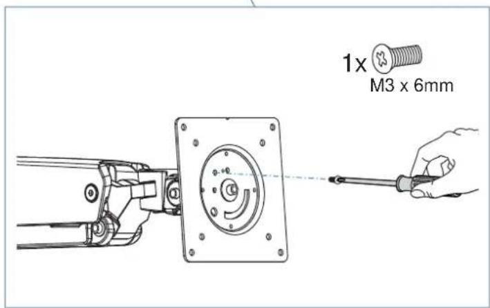
7
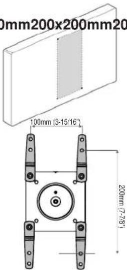
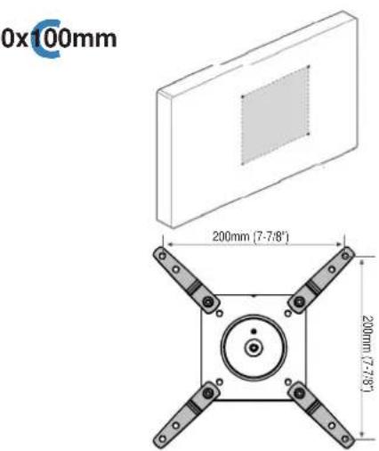
Check size of TV/Monitor hole pattern
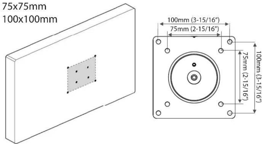
TV/Monitor Hole Pattern Sizes
A
75x75mm
100x100mm

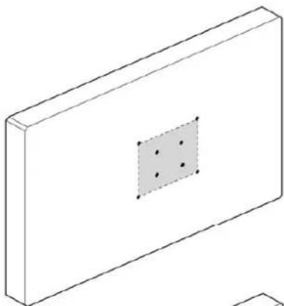
natural_image
Isometric line drawing of a rectangular block with a central square containing four dots, no text or symbols present.B
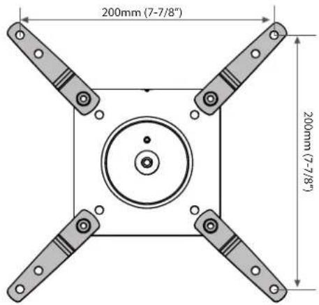
100x200mm
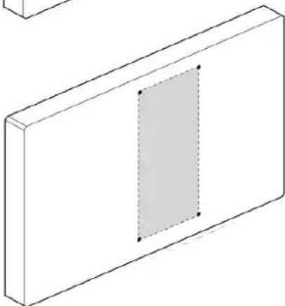
natural_image
Isometric view of a rectangular block with a shaded internal rectangle and two corner dots (no text or symbols)C
200x200mm

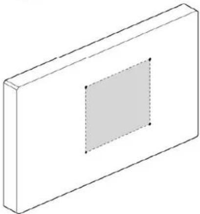
natural_image
Isometric view of a rectangular block with a central square and dashed inner rectangle (no text or symbols)D
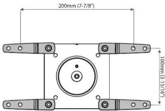
200x100mm

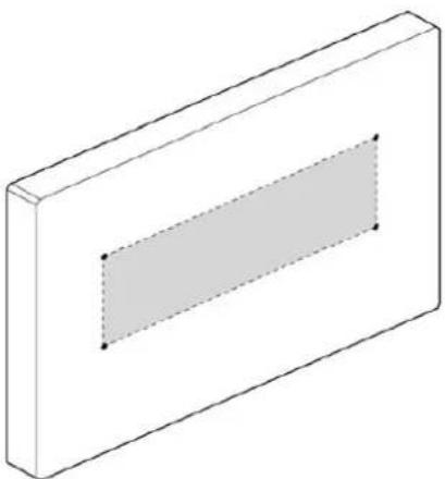
natural_image
Isometric view of a rectangular block with a shaded inner rectangle and two marked points (no text or symbols)VESA Adapter
Configurations
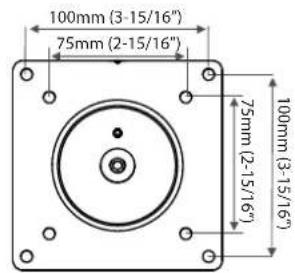
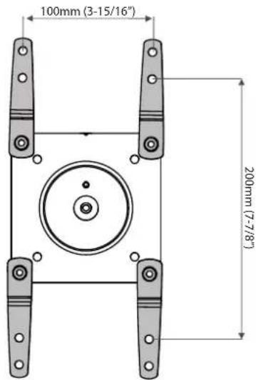
7 Mount Type A TV/Monitor to Arm
A
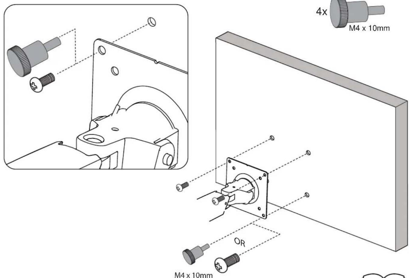
8

B
100x200mm200x200mm200x100mm
D
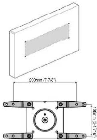
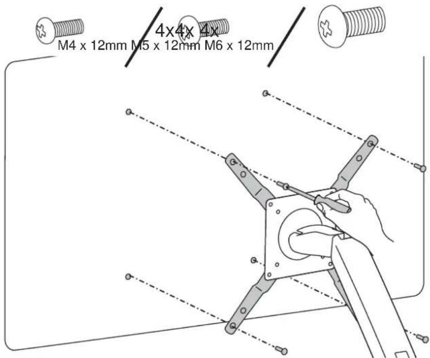
7a Mount VESA Adapters to Arm based on TV/Monitor hole pattern size (B, C, or D).
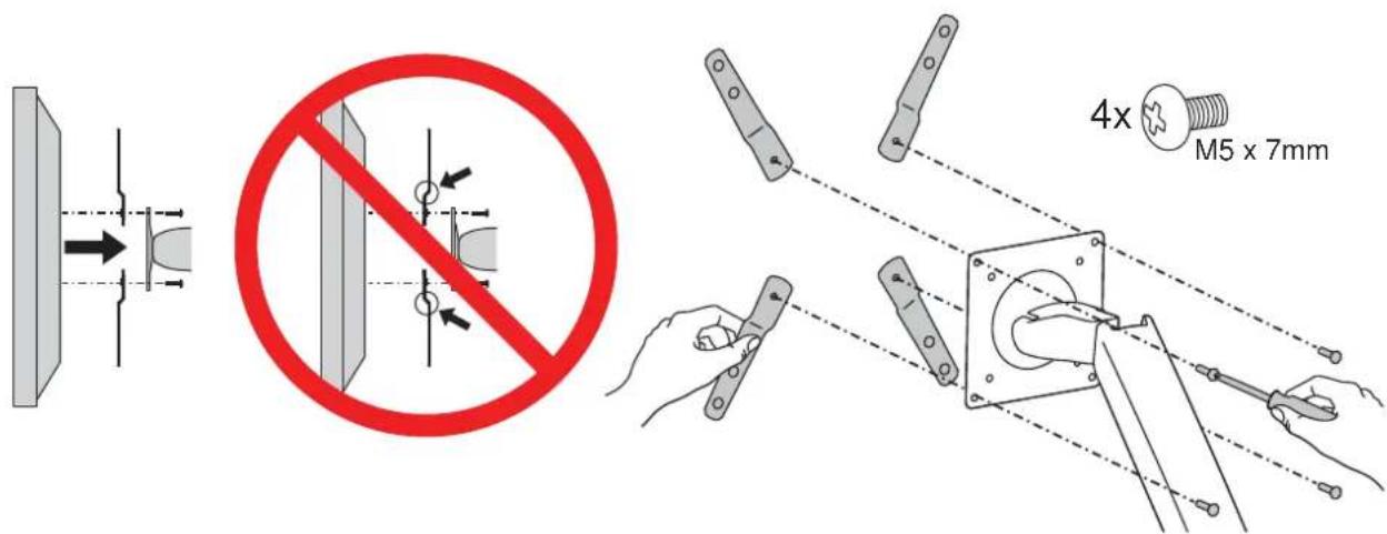
7b Mount Type B, C, or D TV/Monitor to Arm
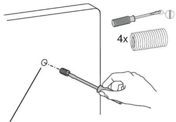
NOTE: To reduce M8 holes for use with M5 screws, or if you have a model with Samsung holder rings, follow the M8M5 KIT instructions on the next page.

M8M5 KIT Instructions
NOTE: Follow this step only if your TV/monitor has M8 holes which need to be reduced to M5.
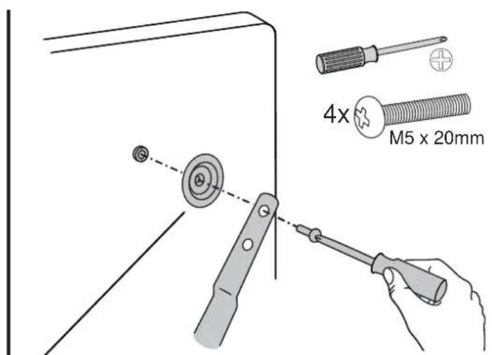
Install M8M5 reducer bushing to TV/Monitor and use M5 x 20 mm monitor screws to secure.
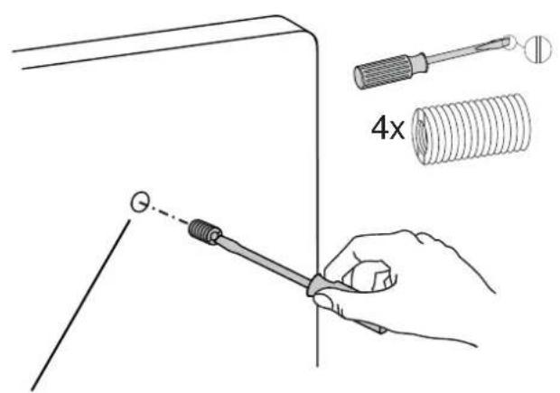
TV/Monitor Mounting M8 size hole
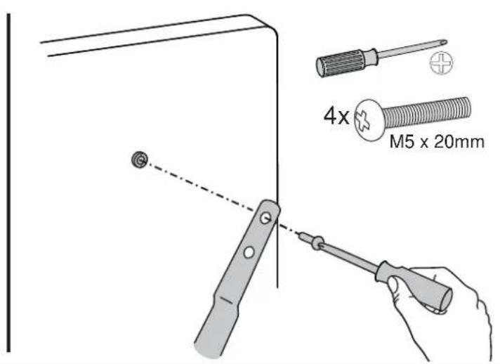
NOTE: Follow this step only for Samsung models using the holder ring.
Install M8M5 reducer bushing to TV/Monitor then use M5 x 20 mm monitor screws and Samsung holder ring to secure.
TV/Monitor Mounting M8 size hole
Holder Ring (Not included *Samsung Only)
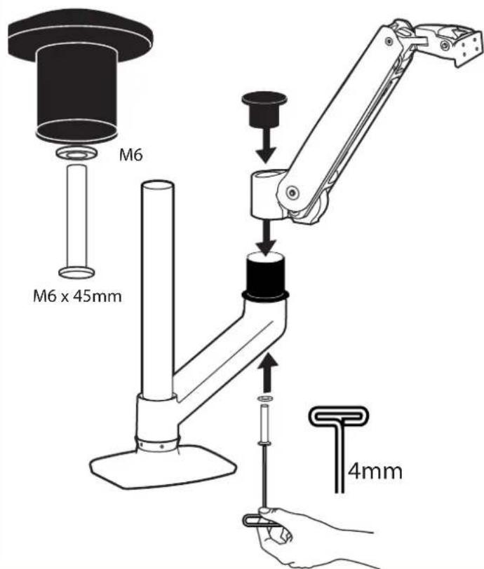
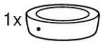
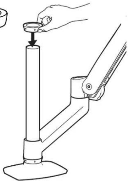
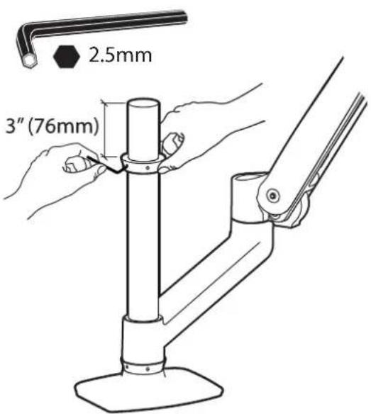
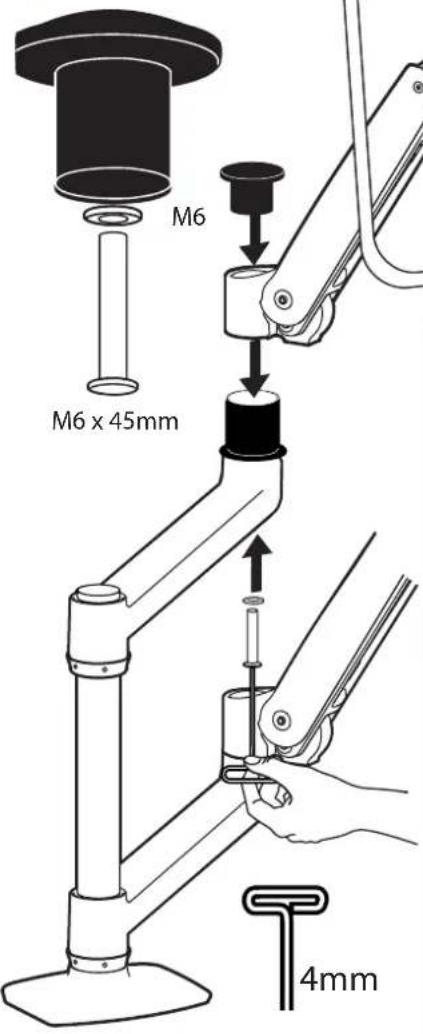
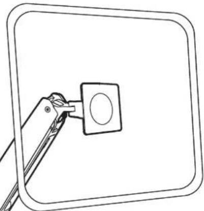
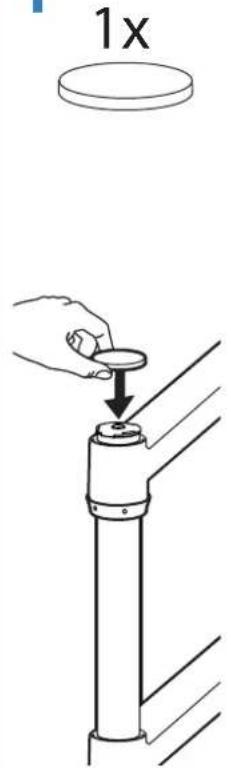
8 Mount extension and arm to pole.
a
natural_image
Line drawing of a hand operating a mechanical lever with a cylindrical component (no text or symbols)b
C
2x
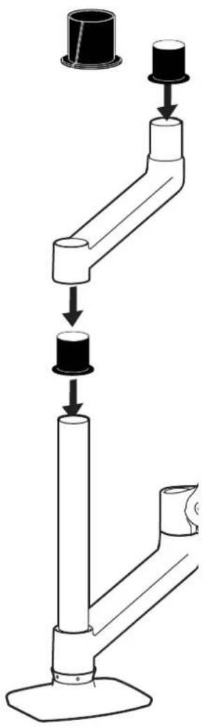
flowchart
graph TD
    A["Top cylindrical component"] --> B["Component 1"]
    B --> C["Component 2"]
    C --> D["Component 3"]
    D --> E["Bottom cylindrical component"]
d
natural_image
Line drawing of a tool interacting with a square button (no text or symbols)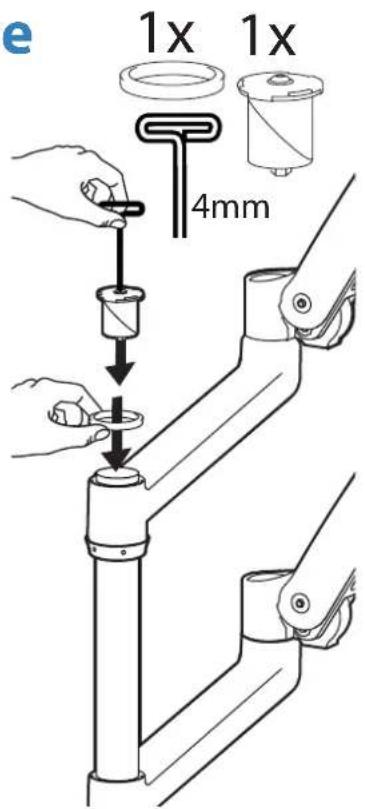
f
9
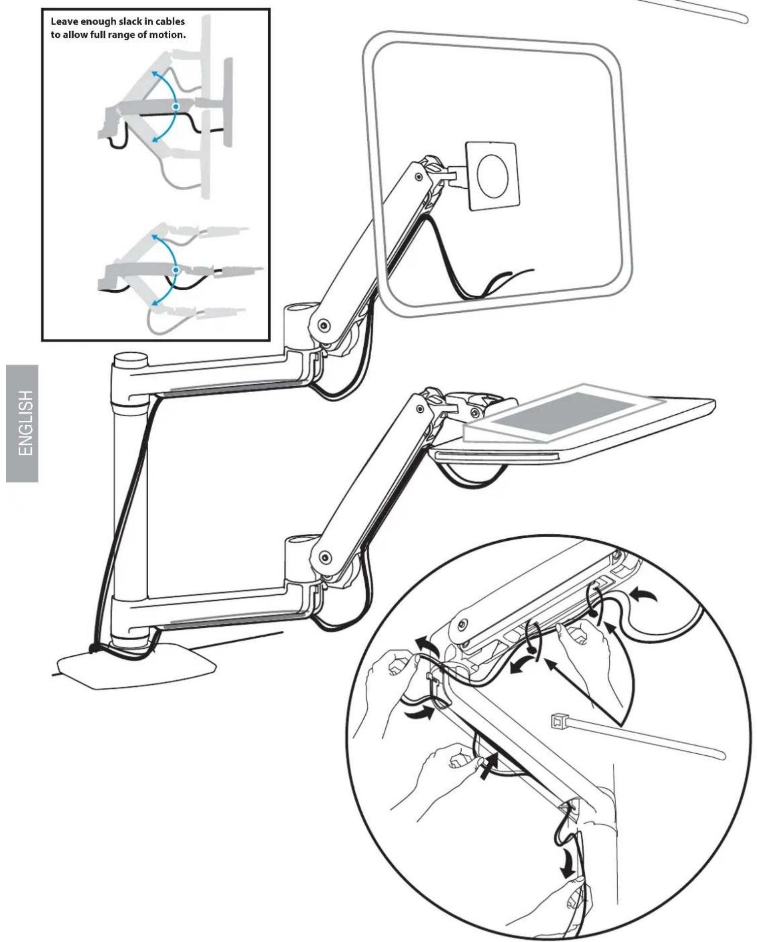
Organize and route cables

Adjustment Step
Important! You will need to adjust this product after installation is complete. Make sure all your equipment is properly installed on the product before attempting adjustments. This product should move smoothly and easily through the full range of motion and stay where you set it. If movements are too easy or difficult or if product does not stay in desired positions, follow the adjustment instructions to create smooth and easy movements. Depending on your product and the adjustment, it may take many turns to notice a difference. Any time equipment is added or removed from this product, resulting in a change in the weight of the mounted load, you should repeat these adjustment steps to ensure safe and optimum operation.
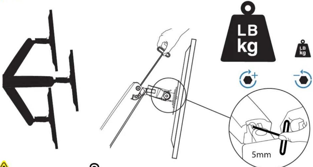
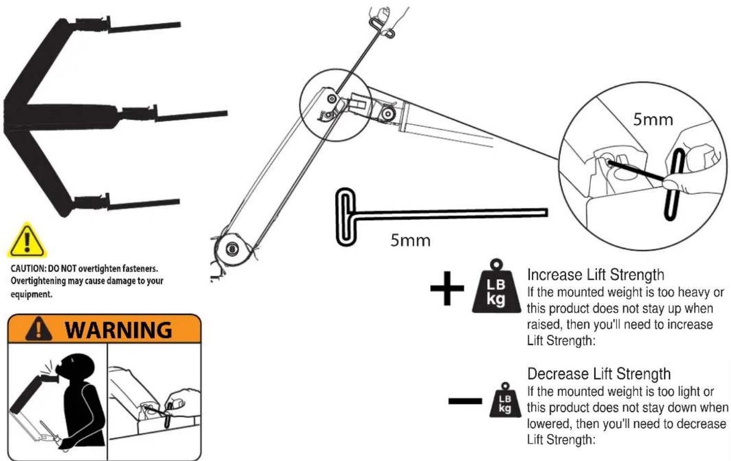
10 To adjust the arm lift:

CAUTION: DO NOT overtighten fasteners. Overtightening may cause damage to your equipment.
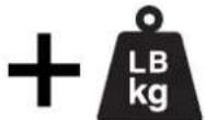
Increase Lift Strength
If the mounted weight is too heavy or this product does not stay up when raised, then you'll need to increase Lift Strength:
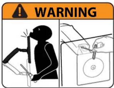
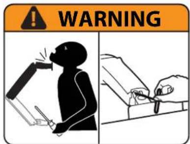
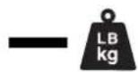
Decrease Lift Strength
If the mounted weight is too light or this product does not stay down when lowered, then you'll need to decrease Lift Strength:
WARNING! Stored Energy Hazard: The arm mechanism is under tension and will move up rapidly, on its own, as soon as attached equipment is removed. For this reason, DO NOT remove equipment unless the arm has been moved to the highest position! Failure to follow this instruction may result in serious personal injury and/or equipment damage!
11 To adjust the TV/monitor tilt:
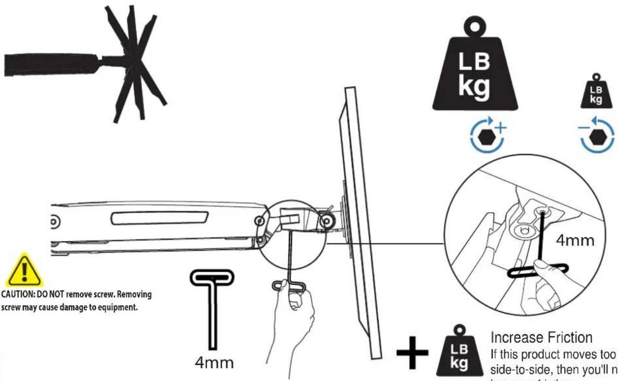
Decrease Friction
If this product is too difficult to move from side-to-side, then you'll need to decrease friction:
12 Lift – Up and down
WARNING! Stored Energy Hazard: The arm mechanism is under tension and will move up rapidly, on its own, as soon as attached equipment is removed. For this reason, DO NOT remove equipment unless the arm has been moved to the highest position! Failure to follow this instruction may result in serious personal injury and/or equipment damage!
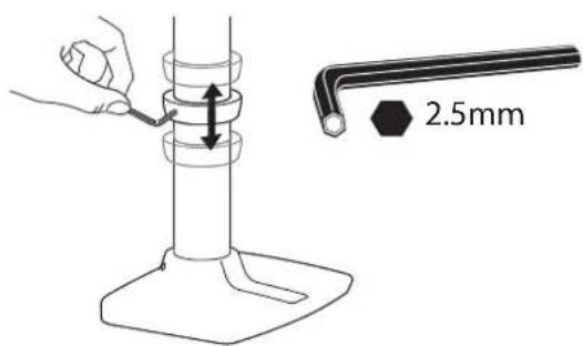
13 To adjust height on pole:
How to remove this tilting feature:
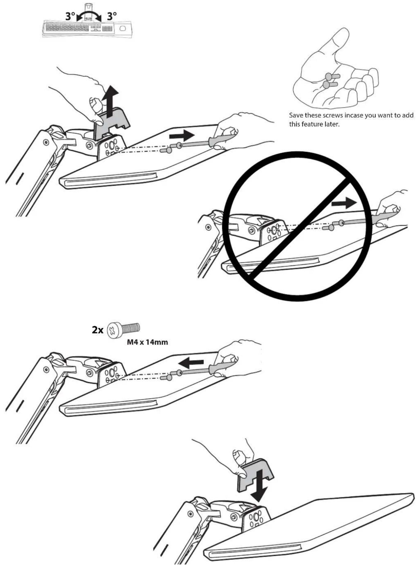
Save these screws incase you want to add this feature later.
Set Your Workstation to Work For YOU!
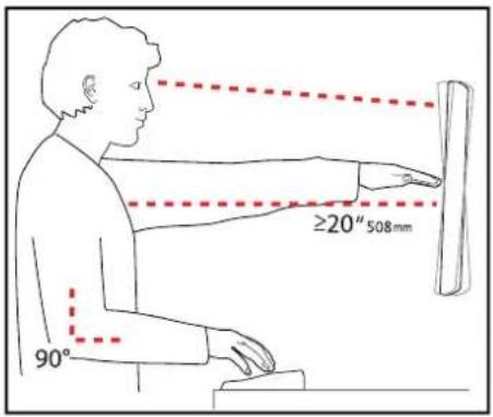
Learn more about ergonomic computer use at: www.computingcomfort.org
Height Position top of screen slightly below eye level.
Position keyboard at about elbow height with wrists fl at.
Distance Position screen an arm's length from face—at least 20" (508mm).
Position keyboard close enough to create a 90° angle in elbow.
Angle Tilt screen to eliminate glare.
Tilt the keyboard back 10° so that your wrists remain fl at.
To Reduce Fatigue
Breathe - Breathe deeply through your nose.
Blink - Blink often to avoid dry eyes.
Break • 2 to 3 minutes every 20 minutes
- 15 to 20 minutes every 2 hours.
For service and warranty visit www.ergotron.com
For local customer care phone numbers visit: http://contact.ergotron.com

NOTE: When contacting customer service, reference the serial number.
natural_image
Technical diagram of a mechanical assembly with a highlighted circular component and a separate rectangle (no text or symbols)
While Ergotron, Inc. makes every effort to provide accurate and complete information on the installation and use of its products, it will not be held liable for any editorial errors or omissions (including those made in the process of translation from English to another language), or for incidental, special or consequential damages of any nature resulting from furnishing this instruction and performance of equipment in connection with this instruction. Ergotron, Inc. reserves the right to make changes in the product design and/or product documentation without notification to its users. For the most current product information, or to know if this document is available in languages other than those herein, please contact Ergotron. No part of this publication may be reproduced, stored in a retrieval system, or transmitted in any form or by any means, electronic, mechanical, photocopying, recording or otherwise without the prior written consent of Ergotron, Inc.,1181 Trapp Road, Eagan, Minnesota, SS121, USA Patents Pending and Patented U.S. & Foreign. Ergotron is a registered trademark of Ergotron, Inc.
Americas Sales and
Corporate Headquarters
EMEA Sales
St. Paul, MN USA
(800) 888-8458
+1-651-681-7600
www.ergotron.com
sales@ergotron.com
Amersfoort, The Netherlands
+31 33 45 45 600
www.ergotron.com
info.eu@ergotron.com
APAC Sales
Tokyo, Japan
www.ergotron.com
apaccustomerservice@ergotron.com
Worldwide OEM Sales
www.ergotron.com
info.oem@ergotron.com
- Tools Needed
- Features & Specifications
- Safety
- Components
- Desk Placement
- Mount extension and arm to pole.
- Portrait / Landscape Options
- 7
- Check size of TV/Monitor hole pattern
- Mount Type A TV/Monitor to Arm
- 7a Mount VESA Adapters to Arm based on TV/Monitor hole pattern size (B, C, or D).
- 7b Mount Type B, C, or D TV/Monitor to Arm
- M8M5 KIT Instructions
- Mount extension and arm to pole.
- Adjustment Step
- To adjust the arm lift:
- Lift – Up and down
- To adjust height on pole:
- How to remove this tilting feature:
- Learn more about ergonomic computer use at: www.computingcomfort.org
Brand : Ergotron
Model : WorkFit 45-405-026
Category : Flat screen mount