
LX Sit-Stand Wall Mount LCD Arm - Flat screen mount Ergotron - Free user manual and instructions
Find the device manual for free LX Sit-Stand Wall Mount LCD Arm Ergotron in PDF.


| Product Type | Flat screen wall mount |
| Brand | Ergotron |
| Model | LX Sit-Stand Wall Mount LCD Arm |
| Application | Office, home, sit-stand workstation |
| Mounting Type | Wall mount, articulating arm |
| Vertical Adjustment | Continuous lift motion (sit-stand range: up to 13 in) |
| Horizontal Reach | Up to 25 in from wall |
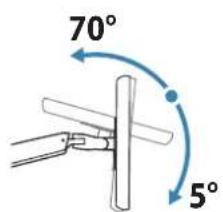
| Tilt | +75° / -5° |
| Pan | 360° |
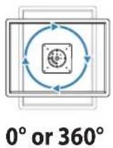
| Rotation | 360° (portrait/landscape) |
| Weight Capacity | Up to 14 kg (30 lb) |
| VESA Compatibility | 75x75 mm, 100x100 mm (adapter included for larger) |
| Display Size Support | Up to 32 in (81 cm) |
| Material | Steel and aluminum construction |
| Finished Color | Black (standard) |
| Product Dimensions (arm) | 100 x 120 x 640 mm (approx.) |
| Product Weight (arm) | 3.6 kg (8 lb) approx. |
| Power Supply | Not required (manual adjustment) |
| Included Components | Wall mount, arm assembly, hardware kit, cable management clips |
| Warranty | 10 years (onsite service) |
| User Manual | Available for free download at notice-facile.com |
Frequently Asked Questions - LX Sit-Stand Wall Mount LCD Arm Ergotron
User questions about LX Sit-Stand Wall Mount LCD Arm Ergotron
0 question about this device. Answer the ones you know or ask your own.
Ask a new question about this device
Download the instructions for your Flat screen mount in PDF format for free! Find your manual LX Sit-Stand Wall Mount LCD Arm - Ergotron and take your electronic device back in hand. On this page are published all the documents necessary for the use of your device. LX Sit-Stand Wall Mount LCD Arm by Ergotron.
USER MANUAL LX Sit-Stand Wall Mount LCD Arm Ergotron
natural_image
Line drawing of a wall-mounted device with a mounted switch, mounted on a panel (no text or symbols)
www.ergotron.com
USA 1-800-888-8458
Europe +31 (0)33-45 45 600
China 86-769-86018920

natural_image
Icon of a person reading a document inside a blue circle (no text or symbols)IMPORTANT! This product will need tension adjustments once installation is complete. Make sure all equipment is properly installed on the product before attempting range of motion or tension adjustments. Any time equipment is added or changed on this product resulting in a different mounted weight, you should repeat the adjustment steps to ensure safe and optimum operation. This product should move smoothly and easily through the full range of motion and stay where you set it. If movement is difficult or the product does not stay where you set it, follow the adjustment instructions to loosen or tighten the tension to create a smooth, easy motion. Depending on your product and the adjustment, it may take many turns to notice a difference.
For service and warranty visit www.ergotron.com
| A | B | C | D | |
| 1 |  | 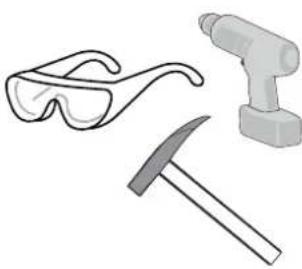 | 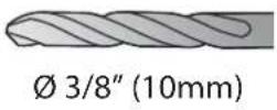 | Wood Stud MountingConcrete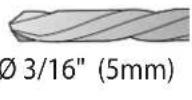 |
| 2 | 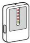 | Stud FinderLocalizador de largueros de maderaStud FinderAuswahl von MontagematerialPositiebepaler balkenRilevatore di montantiスタッド ファインダー螺栓探测器ス터드 과인더 |  |  |

| A | B | C | D | |
| 1 | 1x1x 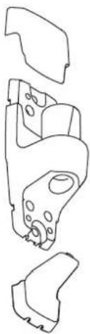 | 1v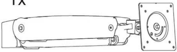 | 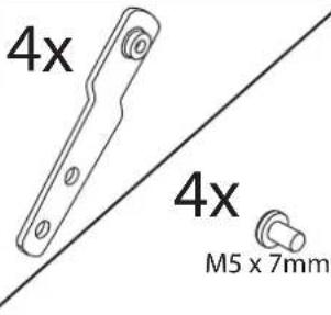 | |
| 2 | 1x | 1> 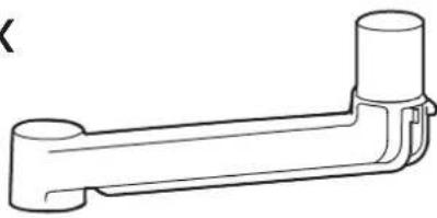 | 4x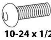 !" !" | |
| 3 | 2x | 4x M4 x 10mm M4 x 10mm | 4x 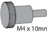 | 2x2x 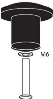 2x M6 x 45mm 2x M6 x 45mm |
| 4 | 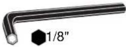 | 1x M3 x 6 M3 x 6 | 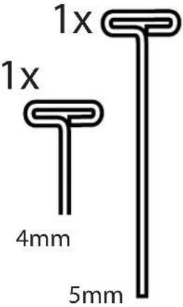 | |
| 5 | 2x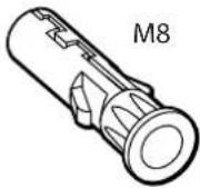 | 2x[Mi 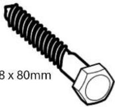 | M8 M5 Kit4: 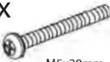 M5x201111 M5x201111 | |
| 6 | 4x 4x 4x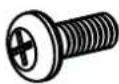 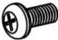 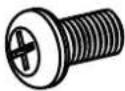 M4x12 M5x12 M6x12 M4x12 M5x12 M6x12 | 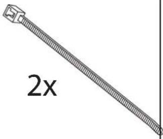 | 4x M8-M5 Reducer M8-M5 Reducer | |
1
Determine mounting location:
 | 4 x 3 | 16 x 9 | |||
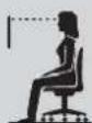 | 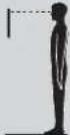 | 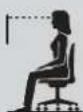 | 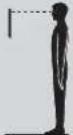 | ||
| 15" | 34.1"(866 mm) | 50.1"(1273 mm) | 34.9"(886 mm) | 50.9"(1293 mm) | |
| 16" | 33.8"(859 mm) | 49.8"(1265 mm) | 34.6"(879 mm) | 50.6"(1285 mm) | |
| 18.1" | 33.1"(841 mm) | 49.1"(1247 mm) | 34.1"(866 mm) | 50.1"(1273 mm) | |
| 20" | 32.6"(828 mm) | 48.6"(1234 mm) | 33.7"(856 mm) | 49.7"(1262 mm) | |
| 21" | 32.3"(820 mm) | 48.3"(1227 mm) | 33.4"(848mm) | 49.4"(1255 mm) | |
| 22" | 32"(813 mm) | 48"(1219 mm) | 33.2"(843 mm) | 49.2"(1250 mm) | |
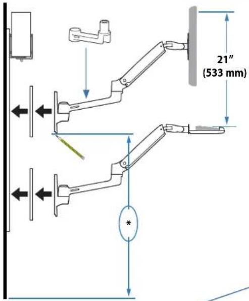
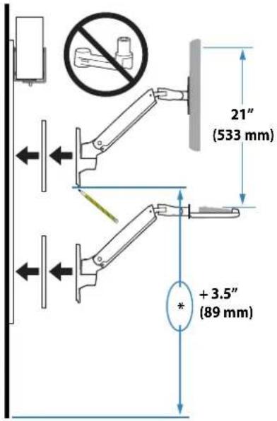
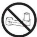
For configurations without extension, add 3.5" (89 mm) to the mounting height from the table above.
These mounting heights assume your monitor mounting holes are located in the center, relative to the monitor screen. If your monitor's mounting holes are located off-center (vertically), you can adjust your mounting height accordingly. ie. (Back of Monitor)
natural_image
Mechanical component diagram showing a piston and housing assembly with an arrow indicating direction (no text or symbols)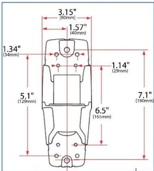
!
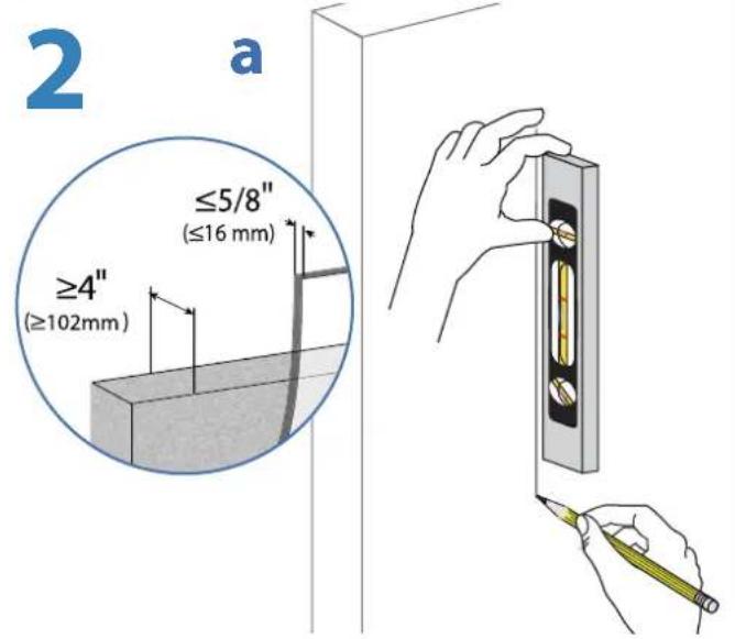
CAUTION: Make sure the wall mount bracket is level, flush and snug to the wall surface. DO NOT OVERTIGHTEN THE BOLTS.
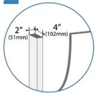
Wood
Madera
Bois

WARNING: Ensure that the wall structure is capable of supporting four times the total weight of mounted equipment. Mounting to wall surfaces that do not meet this criteria may result in an unstable, unsafe condition which could lead to personal injury and/or property damage. Consult a construction professional if you have any doubt about what this means in regard to your particular application.
NOTE: Fasteners may unwind due to vibration caused by movement of mounting solution over time. Inspect mounting solution for loose fasteners on a routine basis. If desired, apply a light duty thread locking adhesive to fasteners before installation to prevent back-out.


When attaching to Pole Clamps, use 10-24 x 5/8" screws included with pole brackets, Do NOT use 10-24 x 1/2" screws

Wood Stud Mount
2
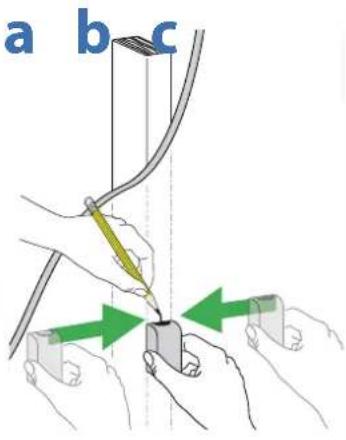
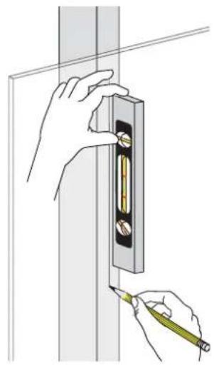
natural_image
Illustration of hands installing or adjusting a wall-mounted component with a pencil (no text or symbols present)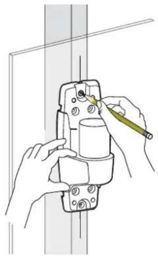
natural_image
Illustration of hands installing or adjusting a mechanical component with a tool (no text or symbols visible)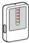
Stud Finder
Localizador de largueros de madera
Stud Finder
Auswahl von Montagematerial
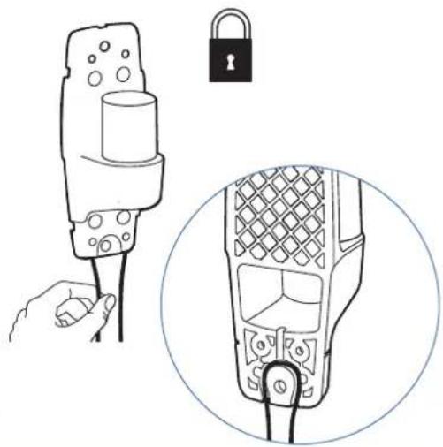
Optional locking feature (customer supplied lock)
natural_image
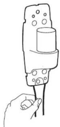
Line drawing of a handheld device with a hand holding its cable and a close-up view of its internal components (no text or symbols)3
b
C
!
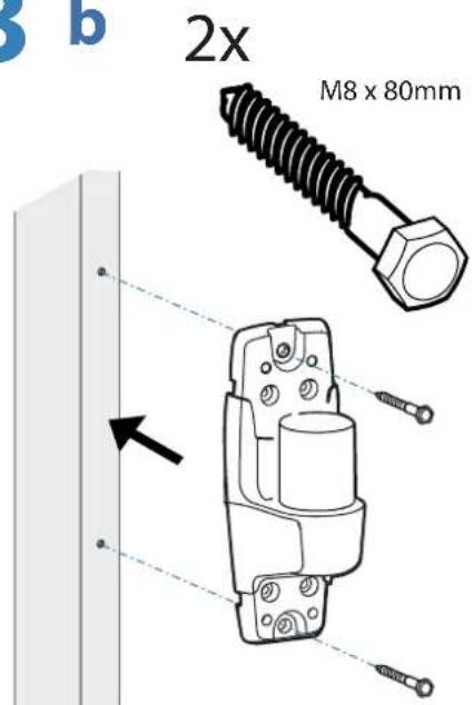
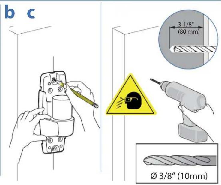
CAUTION: Make sure the wall mount bracket is level, fl ush and snug to the wall surface.
DO NOT OVER-
TIGHTEN
THE BOLTS.
Concrete Wall Mount

WARNING:
Mounting holes must be at least 3-1/8" (80mm) deep and must be located within solid concrete, not mortar or covering material. If you drill into an area of concrete that is not solid, reposition mounting holes until both anchors can be fully inserted into solid concrete!
AVISO:
Anchors that are not fully set in solid concrete will not support the applied load resulting in an unstable, unsafe condition which could lead to personal injury and/or property damage. Consult a construction professional if you have any doubt about what this means in regard to your particular situation.
AVISO:
Optional locking feature (customer supplied lock)

natural_image
Hand holding a tool with a cylindrical component inserted into a mechanical housing (no text or symbols visible)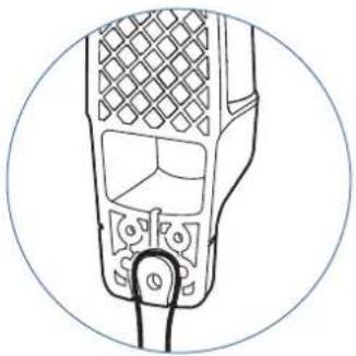
natural_image
Line drawing of a handheld electronic device with a mesh grille and connector (no text or symbols)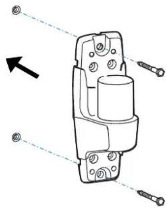
natural_image
Technical line drawing of a mechanical component with bolt holes and threaded fasteners (no text or symbols)C
!
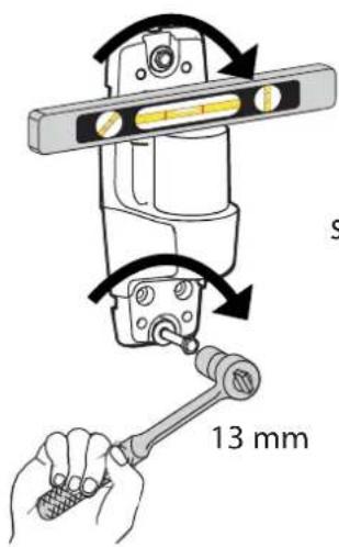
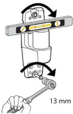
CAUTION: Make sure the wall mount bracket is level, fl ush and snug to the wall surface.
DO NOT OVERTIGHTEN THE BOLTS.
4
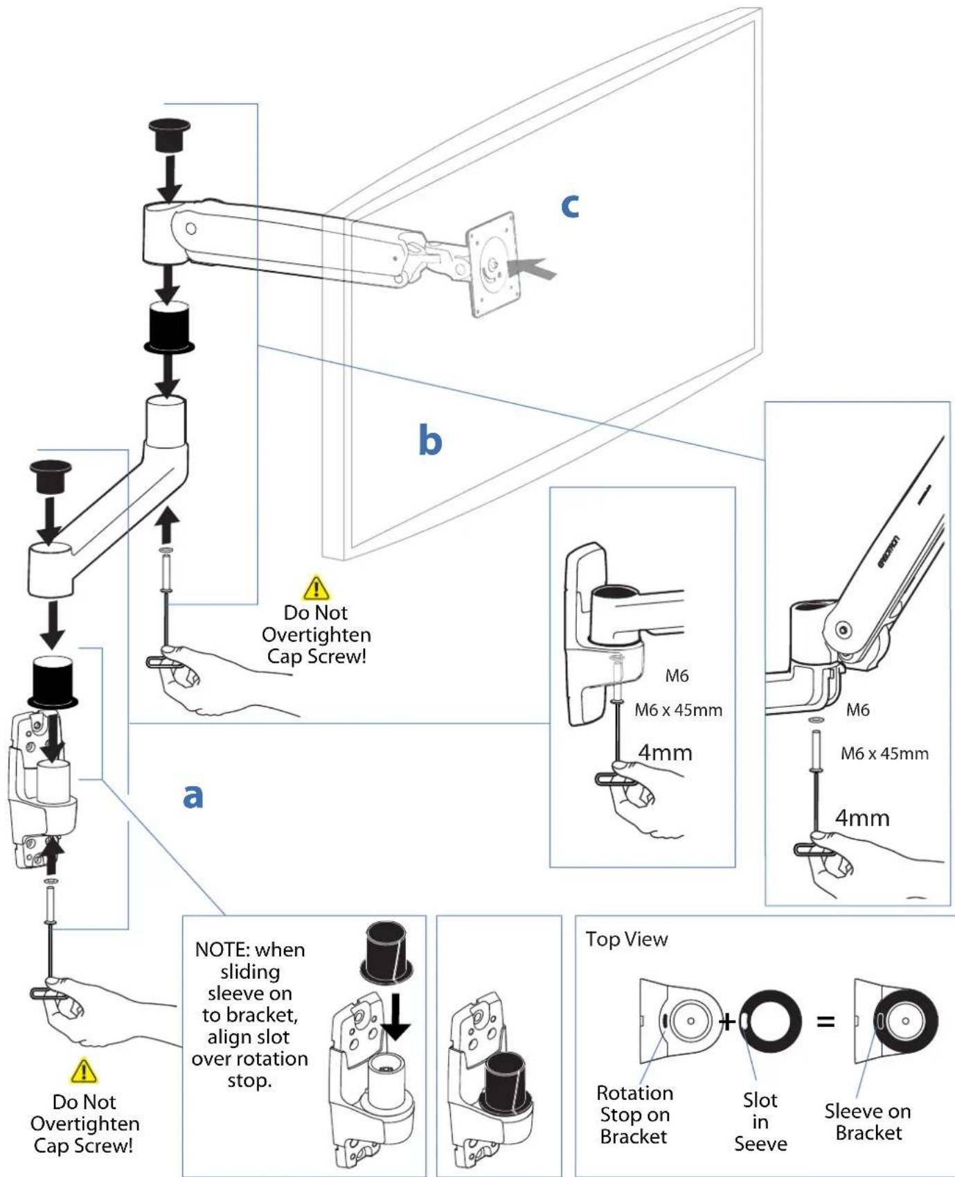
Mount extension and arm to wall bracket.
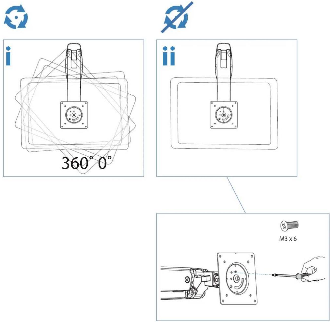
5 Portrait / Landscape Options
OPTION i If you want full 360° portrait/landscape rotation, skip to step 8 on the next page.
OPTION ii If you do not want your TV/Monitor to rotate all all, you can stop rotation by inserting the xx set screw.
6
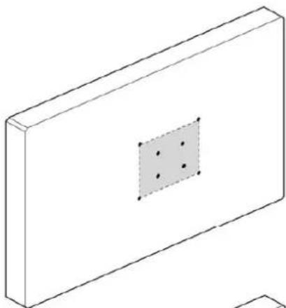
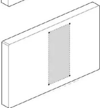
Check size of TV/Monitor hole pattern
TV/Monitor Hole Pattern Sizes
A
75x75mm
100x100mm

natural_image
Isometric line drawing of a rectangular block with a central square containing four dots, no text or symbols present.B
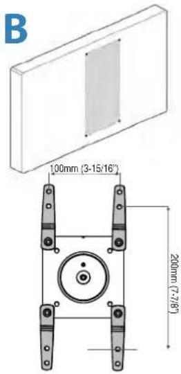
100x200mm

natural_image
Isometric view of a rectangular block with a shaded internal rectangle and two corner dots (no text or symbols)C
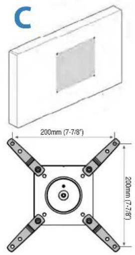
200x200mm

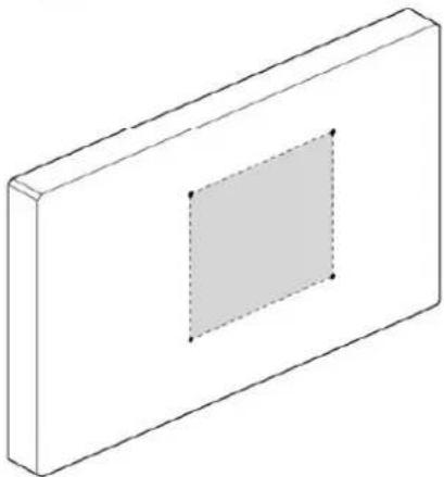
natural_image
Isometric view of a rectangular block with a central square and dashed inner rectangle (no text or symbols)D
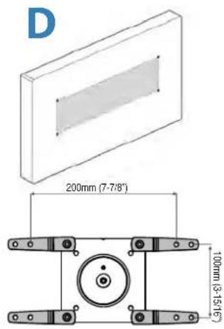
200x100mm

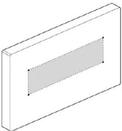
natural_image
Isometric view of a rectangular block with a shaded inner rectangle and two marked points (no text or symbols)VESA Adapter
Configurations
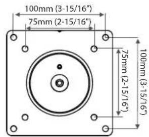
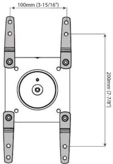
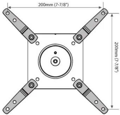
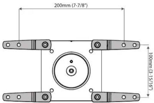
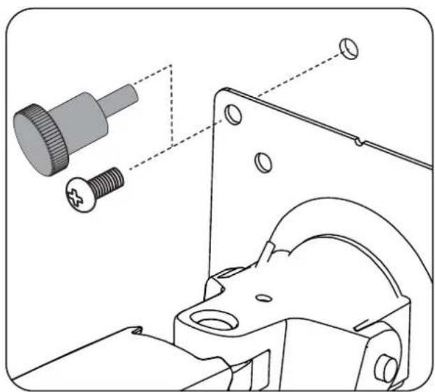
7 Mount Type A TV/Monitor to Arm
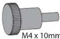
4x

M4 x 10mm
A
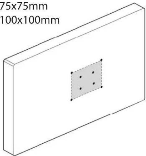
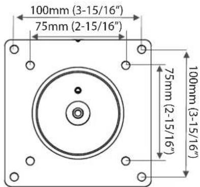
natural_image
Technical diagram showing mechanical assembly with a screw and pin, no text or symbols present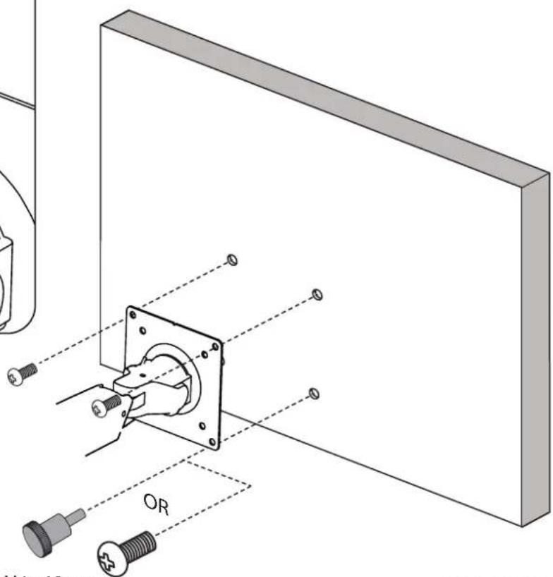
M4 x 10mm
8

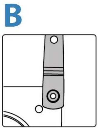
7 Mount VESA Adapters to Arm based on TV/Monitor hole pattern size (B, C, or D).
natural_image
Pure mechanical component diagram without any text, numbers, or symbols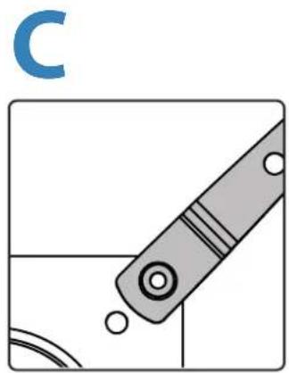
natural_image
Diagram of a mechanical tool with circular components and a blue letter 'C' in the top-left corner (no text or symbols on the tool itself)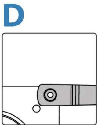
natural_image
Pure technical diagram of a mechanical component with no text, numbers, or symbols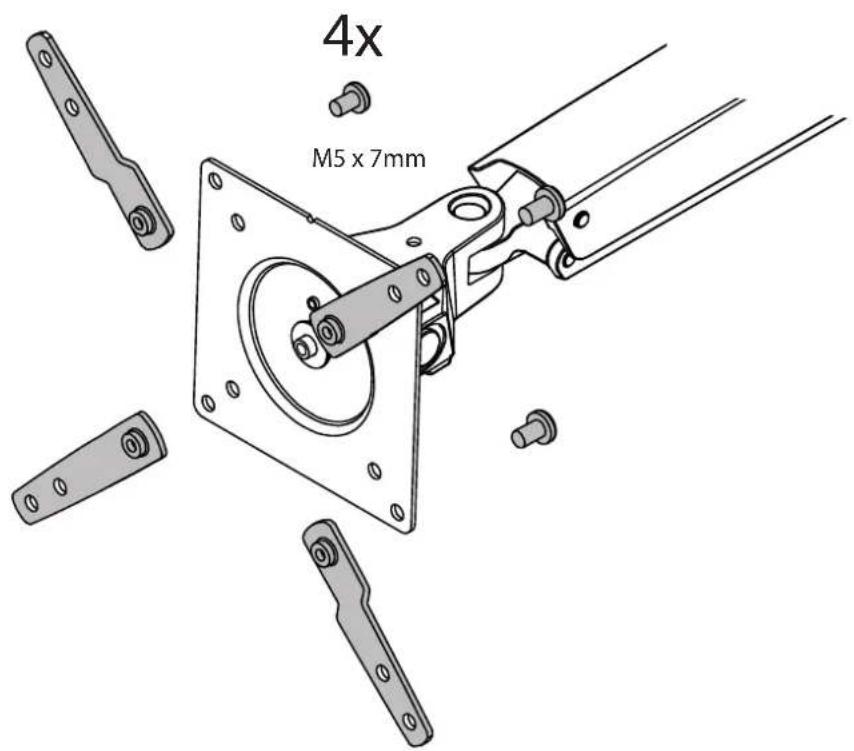
7
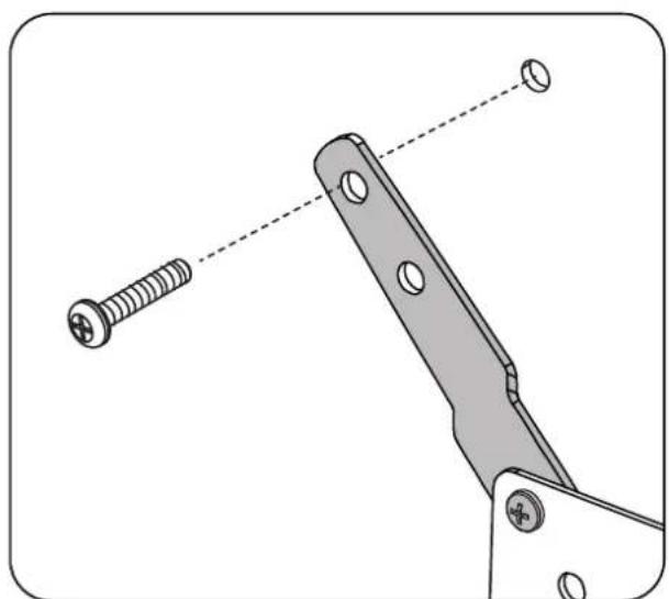
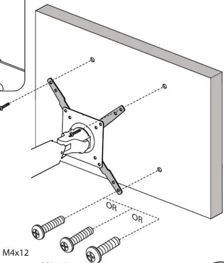
Mount Type B, C, or D TV/Monitor to Arm
natural_image
Technical illustration of a mechanical tool with a screw and two circular holes, no text or symbols presentM4x12 M5x12 M6x12
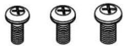
NOTE: To reduce M8 holes for use with M5 screws, or if you have a model with Samsung holder rings, follow the M8M5 KIT instructions on the next page.

M6x12
8

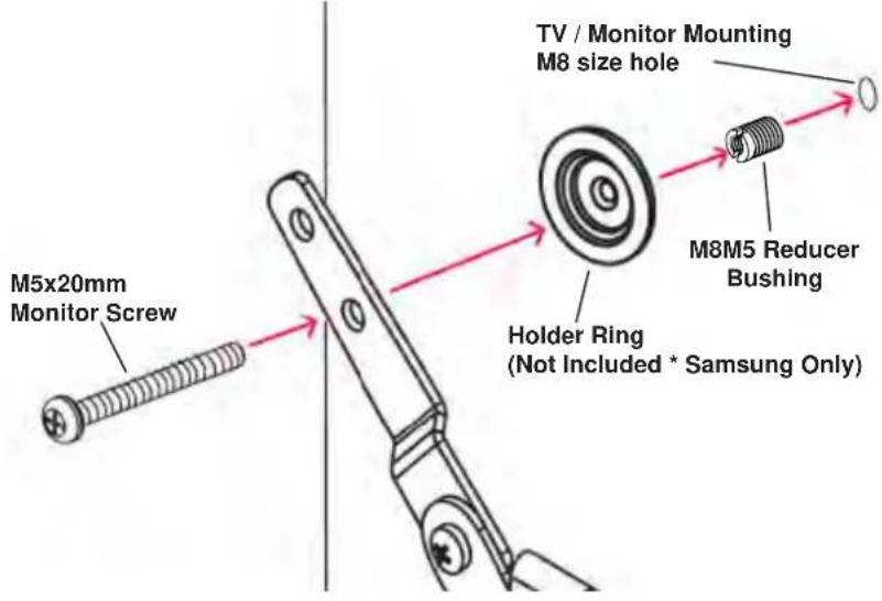
M8M5 KIT Instructions
NOTE: follow this step only if your TV/monitor has M8 holes which need to be reduced to M5 or for Samsung models using the holder ring.
Install M8M5 reducer bushing to TV/Monitor and use M5 x 20 mm monitor screws to secure when using the Samsung holder ring.
8
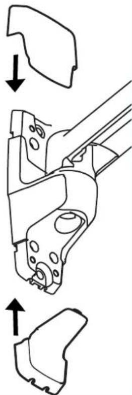
Attach top and bottom bracket covers
natural_image
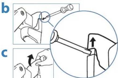
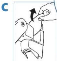
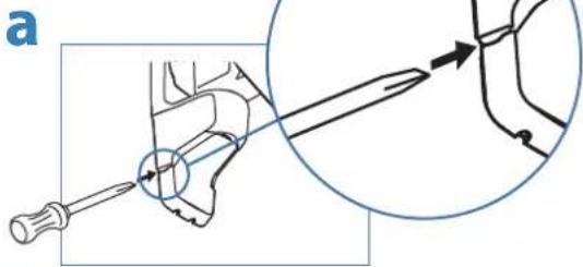
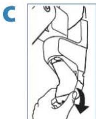
Technical line drawing of a mechanical component with three views (top, front, side), no text or symbols present.To remove covers:
a) Wedge the blade of a flat screwdriver into the gap between the wall mount bracket and the cover. Rotate the blade upward to pry the cover away.
b) Repeat on the opposite side of the wall mount bracket.
c) Once the cover is free on both sides, lift it off.
Top Cover

natural_image
Illustration of hands performing a mechanical operation with an arrow indicating direction (no text or symbols present)Bottom Cover
natural_image
Diagram showing a screwdriver inserted into a mechanical component with an inset close-up of the tool (no text or symbols present)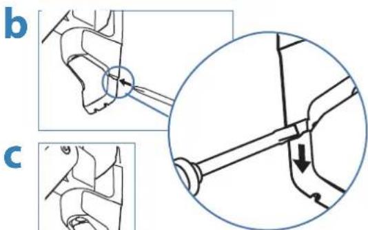
natural_image
Anatomical illustration of a human hand and wrist with a black arrow indicating a specific movement or force (no text or labels present)9
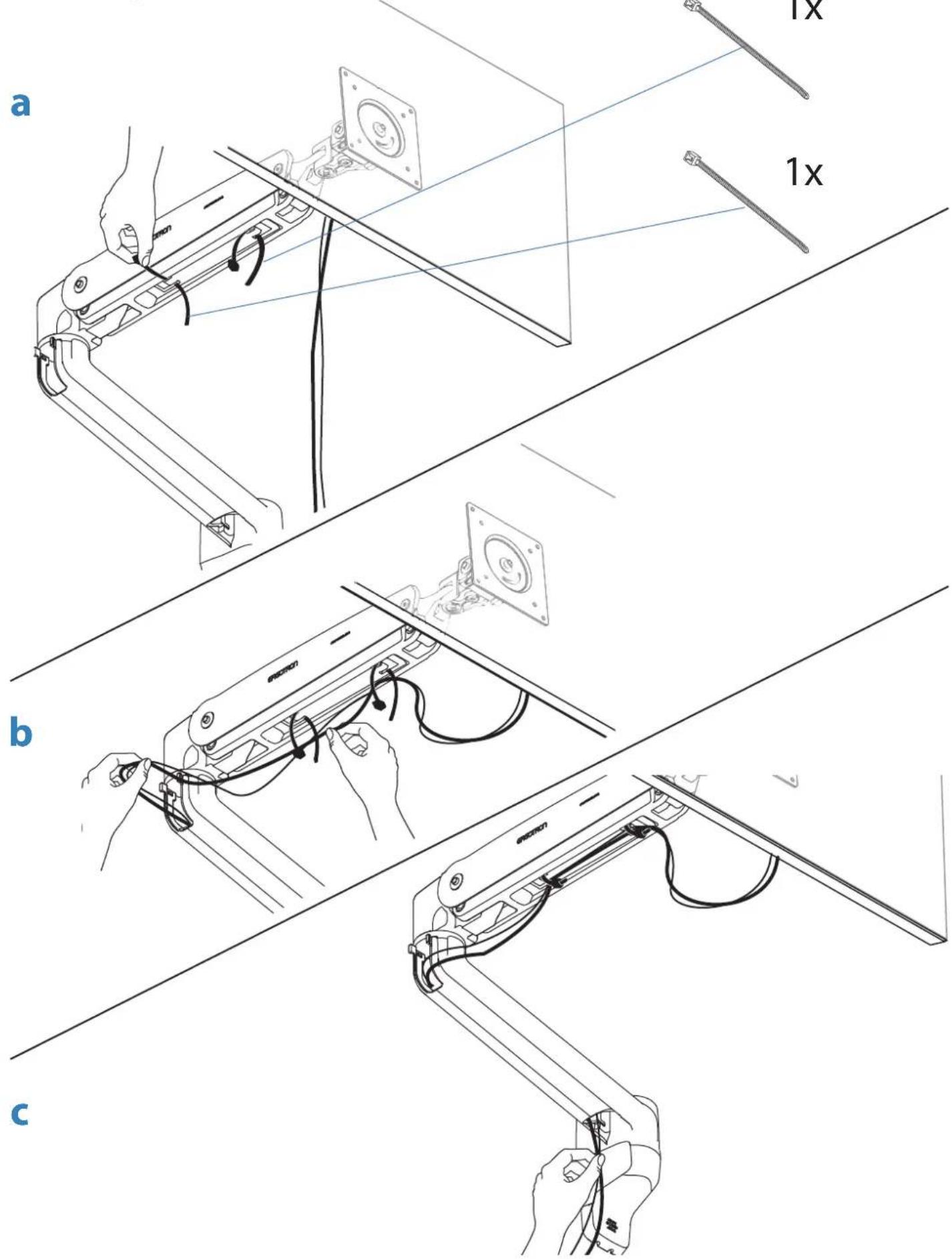
Organize and route cables
10 To adjust the arm lift:
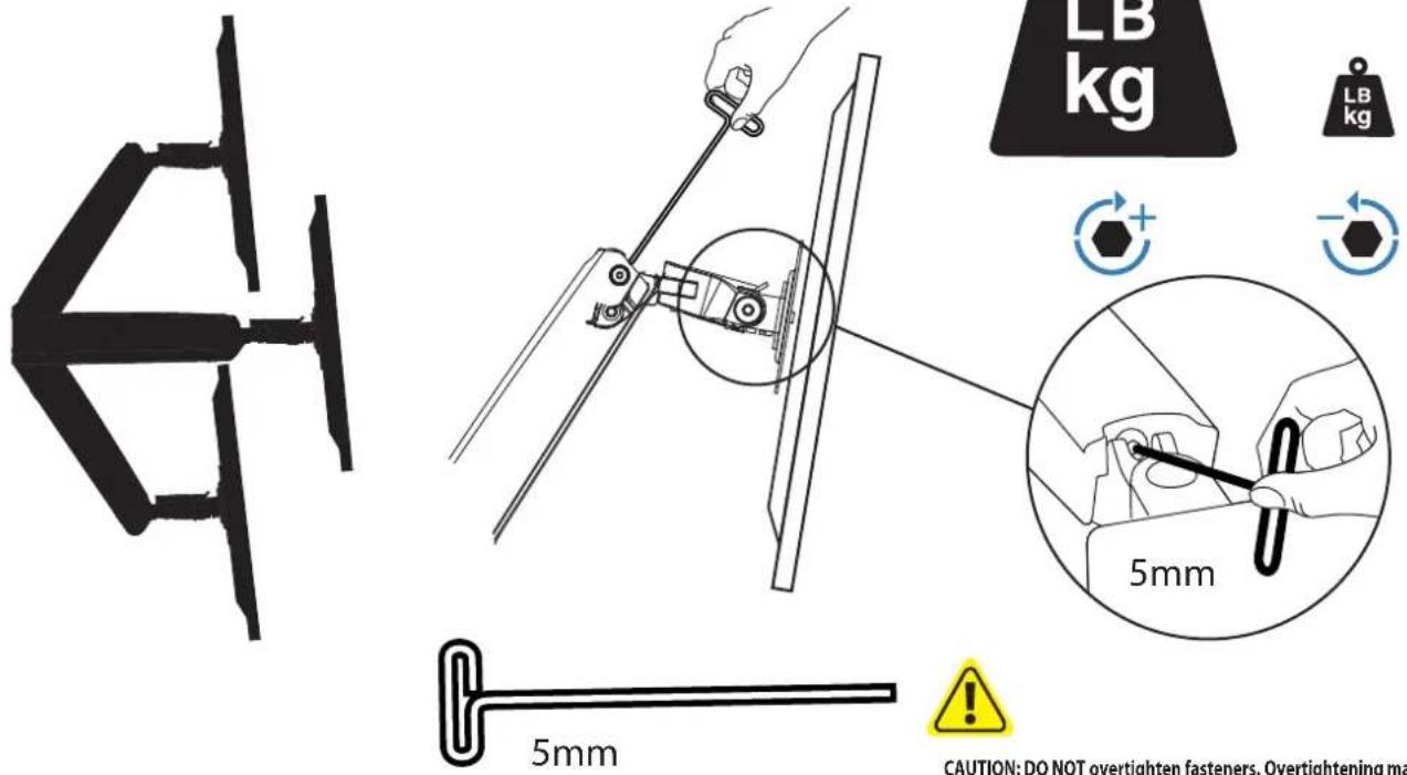
CAUTION: DO NOT overtighten fasteners. Overtightening may cause damage to your equipment.
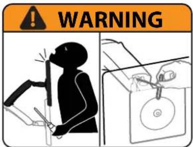
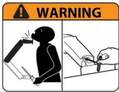
WARNING! Stored Energy Hazard: The arm mechanism is under tension and will move up rapidly, on its own, as soon as attached equipment is removed. For this reason, DO NOT remove equipment unless the arm has been moved to the highest position! Failure to follow this instruction may result in serious personal injury and/or equipment damage!

CAUTION: DO NOT remove screw. Removing screw may cause damage to equipment.
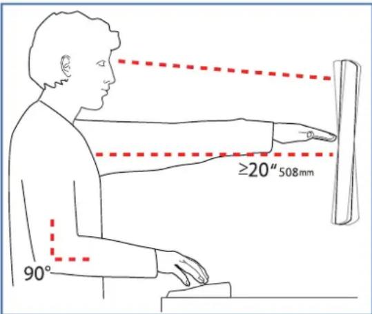
Set Your Workstation to Work For YOU!
Learn more about ergonomic computer use at:
Height Position top of screen slightly below eye level.
Position keyboard at about elbow height with wrists fl at.
Distance Position screen an arm's length from face—at least 20" (508mm).
Position keyboard close enough to create a 90° angle in elbow.
Angle Tilt screen to eliminate glare.
Tilt the keyboard back 10° so that your wrists remain fl at.
© 2012 Ergotron, Inc.
All rights reserved.
While Ergotron, Inc. makes every effort to provide accurate and complete information on the installation and use of its products, it will not be held liable for any editorial errors or omissions (including those made in the process of translation from English to another language), or for incidental, special or consequential damages of any nature resulting from furnishing this instruction and performance of equipment in connection with this instruction. Ergotron, Inc. reserves the right to make changes in the product design and/or product documentation without notification to its users. For the most current product information, or to know if this document is available in languages other than those herein, please contact Ergotron. No part of this publication may be reproduced, stored in a retrieval system, or transmitted in any form or by any means, electronic, mechanical, photocopying, recording or otherwise without the prior written consent of Ergotron, Inc., 1181 Trapp Road, Eagan, Minnesota, 55121, USA Patents Pending and Patented U.S. & Foreign. Ergotron is a registered trademark of Ergotron, Inc.
To Reduce Fatigue
Breathe - Breathe deeply through your nose.
Blink - Blink often to avoid dry eyes.
Break • 2 to 3 minutes every 20 minutes
• 15 to 20 minutes every 2 hours.
Corporate Headquarters
EMEA Sales
St. Paul, MN USA
(800) 888-8458
+1-651-681-7600
www.ergotron.com
sales@ergotron.com
Amersfoort, The Netherlands
+31 33 45 45 600
www.ergotron.com
info.eu@ergotron.com
APAC Sales
Tokyo, Japan
www.ergotron.com
apaccustomerservice@ergotron.com
Worldwide OEM Sales
www.ergotron.com
info.oem@ergotron.com
- 1
- Determine mounting location:
- WARNING:
- AVISO:
- 4
- Mount extension and arm to wall bracket.
- Portrait / Landscape Options
- Mount Type A TV/Monitor to Arm
- Mount VESA Adapters to Arm based on TV/Monitor hole pattern size (B, C, or D).
- 7
- Mount Type B, C, or D TV/Monitor to Arm
- 8
- M8M5 KIT Instructions
- To remove covers:
- To adjust the arm lift:
- Set Your Workstation to Work For YOU!
Brand : Ergotron
Model : LX Sit-Stand Wall Mount LCD Arm
Category : Flat screen mount