LX HD Wall Mount Pivot - Flat screen mount Ergotron - Free user manual and instructions
Find the device manual for free LX HD Wall Mount Pivot Ergotron in PDF.

User questions about LX HD Wall Mount Pivot Ergotron
0 question about this device. Answer the ones you know or ask your own.
Ask a new question about this device
Download the instructions for your Flat screen mount in PDF format for free! Find your manual LX HD Wall Mount Pivot - Ergotron and take your electronic device back in hand. On this page are published all the documents necessary for the use of your device. LX HD Wall Mount Pivot by Ergotron.
USER MANUAL LX HD Wall Mount Pivot Ergotron
text_image
LB kg ≤ 50 lbs. (22.7 kg)Features & Specifications
text_image
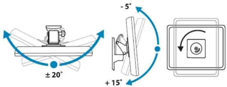
± 20° + 15° - 5°English

For the latest User Installation Guide please visit: www.ergotron.com
English, Español, Français, Deutsch, Nederlands, Italiano, Svenska, 日本語, 汉语
www.ergotron.com
USA: 1-800-888-8458
Europe: +31 (0)33-45 45 600
China: 400-120-3051
Japan: japansupport@ergotron.com
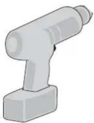
Components

natural_image
3D rendered image of a mechanical tool or bracket (no text or symbols visible)Concrete Wall Mounting
∅ 3/8" (10mm)
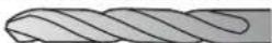
Wood Stud Mounting
∅ 3/16" (5mm)
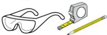
natural_image
Illustration of a pair of eyeglasses and a measuring tool (no text or symbols)
Important! You will need to adjust this product after installation is complete. Make sure all your equipment is properly installed on the product before attempting adjustments. This product should move smoothly and easily through the full range of motion and stay where you set it. If movements are too easy or difficult or if product does not stay in desired positions, follow the adjustment instructions to create smooth and easy movements. Depending on your product and the adjustment, it may take many turns to notice a difference. Any time equipment is added or removed from this product, resulting in a change in the weight of the mounted load, you should repeat these adjustment steps to ensure safe and optimum operation.
1
WALL PLATE MOUNTING INSTRUCTIONS

WARNING:
Ensure that the wall structure is capable of supporting four times the total weight of mounted equipment. Mounting to wall surfaces that do not meet this criteria may result in an unstable, unsafe condition which could lead to personal injury and/or property damage. Consult a construction professional if you have any doubt about what this means in regard to your particular application.

NOTE: Fasteners may unwind due to vibration caused by movement of mounting solution over time. Inspect mounting solution for loose fasteners on a routine basis. If desired, apply a light duty thread locking adhesive to fasteners before installation to prevent back-out.
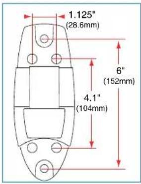
text_image
1.125" (28.6mm) 6" (152mm) 4.1" (104mm)Wood
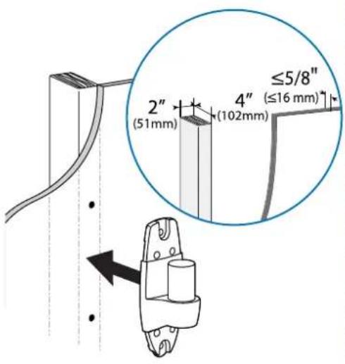
text_image
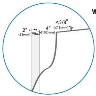
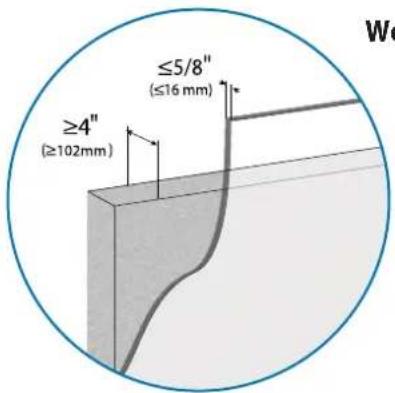
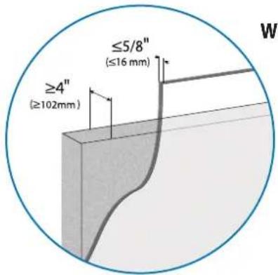
2" (51mm) 4" (102mm) ≤5/8" (≤16 mm)*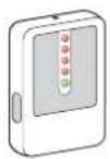
Stud Finder
Concrete Wall Mounting
∅ 3/8" (10mm)
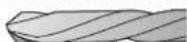
natural_image
3D illustration of a mechanical component with a cylindrical shaft and base (no text or symbols)
Concrete
text_image
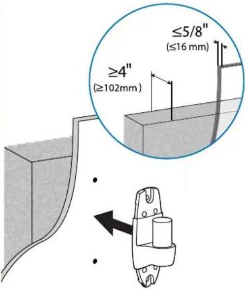
≥4" (≥102mm) ≤5/8" (≤16 mm)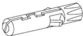
Wood Stud Mounting
∅ 3/16" (5mm)
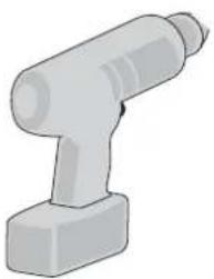
natural_image
Illustration of a mechanical tool or bracket with no visible text or symbols
Ergotron product
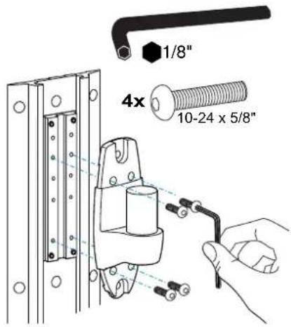
text_image
1/8" 4x 10-24 x 5/8"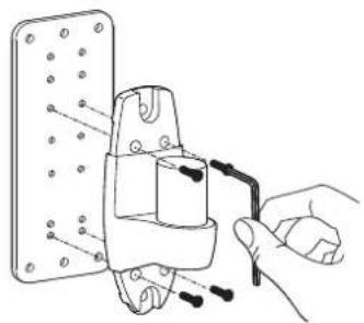
natural_image
Hand holding a tool interacting with a mechanical component (no text or symbols visible)NOTE: Wall Track and Brackets sold separately.
text_image
2" (51mm) 4" (102mm) ≤5/8" (≤16 mm)Wood
text_image
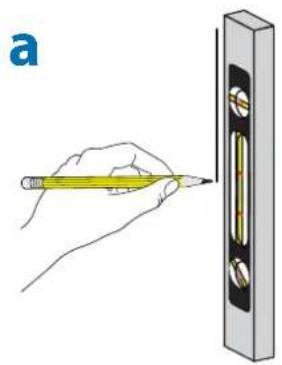
ab
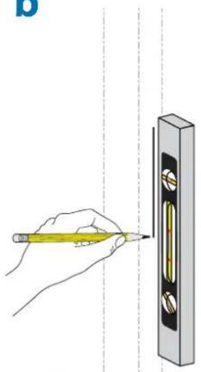
text_image
Diagram showing a hand using a pencil to measure a level in a measurement column, with dashed vertical lines indicating measurement intervals.C
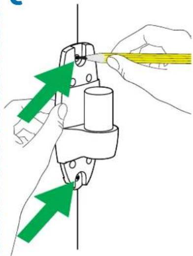
natural_image
Illustration of hands using a tool to adjust or install a mechanical component, with green arrows indicating direction (no text or symbols present)d
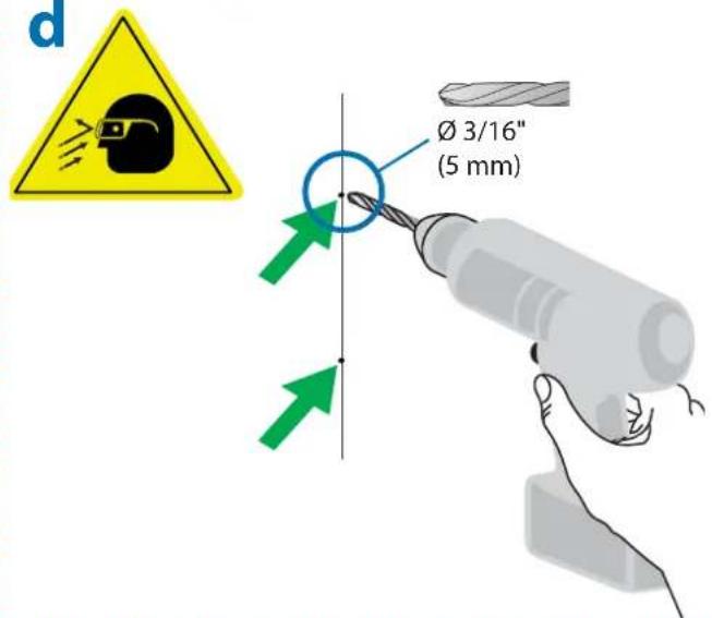
text_image
d Ø 3/16" (5 mm)e
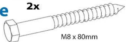
text_image
e 2x M8 x 80mm
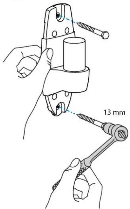
CAUTION: Make sure the wall mount bracket is level, flush and snug to the wall surface. DO NOT OVERTIGHT-EN THE BOLTS.
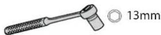
text_image
13 mmf

text_image
ERSUON
text_image
≥4" (≥102mm) ≤5/8" (≤16 mm)Wood Stud Mounting
text_image
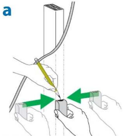
a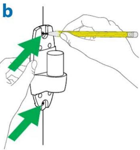
natural_image
Illustration of hands using a tool to adjust or install a mechanical component, with green arrows indicating direction (no text or symbols present)
text_image
C Mounting holes solid concrete, no that is not solid, Ø 3/8" (10 mm) 3-1/8" (80 mm)
WARNING:
Mounting holes must be at least 3-1/8" (80mm) deep and must be located within solid concrete, not mortar or covering material. If you drill into an area of concrete that is not solid, reposition mounting holes until both anchors can be fully inserted into solid concrete!
text_image
≥4" (≥102mm) ≤5/8" (≤16 mm)Wood Stud Mounting

text_image
d 2x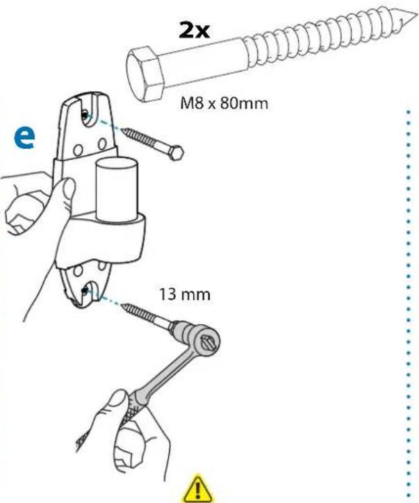
text_image
2x M8 x 80mm 13 mmCAUTION: Make sure the wall mount bracket is level, flush and snug to the wall surface. DO NOT OVERTIGHTEN THE BOLTS.

WARNING:
Anchors that are not fully set in solid concrete will not support the applied load resulting in an unstable, unsafe condition which could lead to personal injury and/or property damage. Consult a construction professional if you have any doubt about what this means in regard to your particular situation.
f

text_image
ERON
2

natural_image
Simple circular diagram with two opposing arrows pointing inward, no text or symbols present.To Stop Portrait/Landscape Rotation insert Screw


360^0^

M4 x 8mm
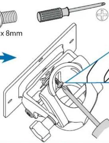
text_image
x 8mm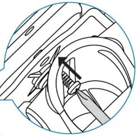
natural_image
Technical line drawing of a mechanical assembly with no visible text or symbolsTV/Monitor Hole Pattern Sizes
VESA Adapter
Configurations
3
Check size of TV/Monitor hole pattern
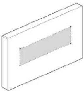
A
75x75mm
100x100mm

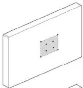
natural_image
Isometric line drawing of a rectangular block with a central square and four small dots, no text or symbols present.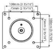
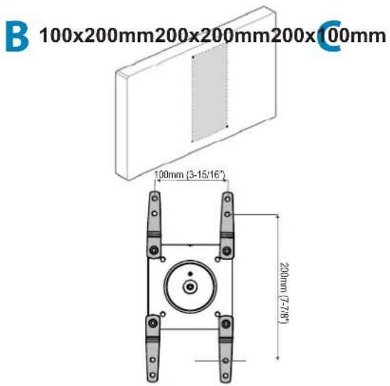
B
100×200mm

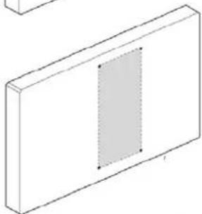
natural_image
Isometric line drawing of a rectangular block with a shaded vertical slot (no text or symbols)
text_image
100mm (3-15/16") 200mm (7-28)C
200×200mm

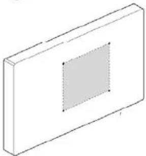
natural_image
Isometric view of a rectangular block with a central square and dashed inner circle (no text or symbols)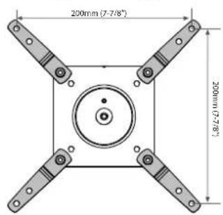
text_image
200mm (7-7/8") 200mm(1-7/8)D
200x100mm

natural_image
Isometric view of a rectangular block with a central rectangular slot (no text or symbols)
text_image
200mm (7-7/8") 100mm (3-15/16)3 Mount Type A TV/Monitor to Arm
A
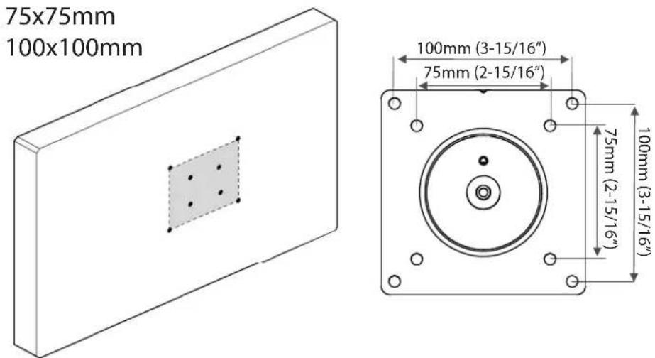
text_image
75x75mm 100x100mm 100mm (3-15/16") 75mm (2-15/16") 75mm (2-15/16") 100mm (3-15/16"75 x 75mm
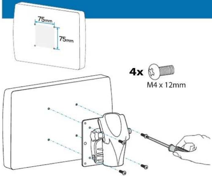
text_image
75mm 75mm 4x M4 x 12mm100 x 100mm
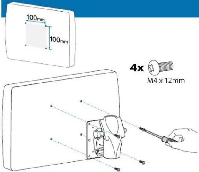
text_image
100mm 100mm 4x M4 x 12mm
text_image
B 100x200mm200x200mm200xC00mm 100mm (3-15/16") 200mm (7-78°)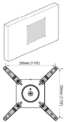
text_image
200mm (7-7/8") 200mm (7-7/8)
text_image
D 200mm (7-7/8") 100mm (3-15/16)3a Mount VESA Adapters to Arm based on TV/Monitor hole pattern size (B, C, or D).
text_image
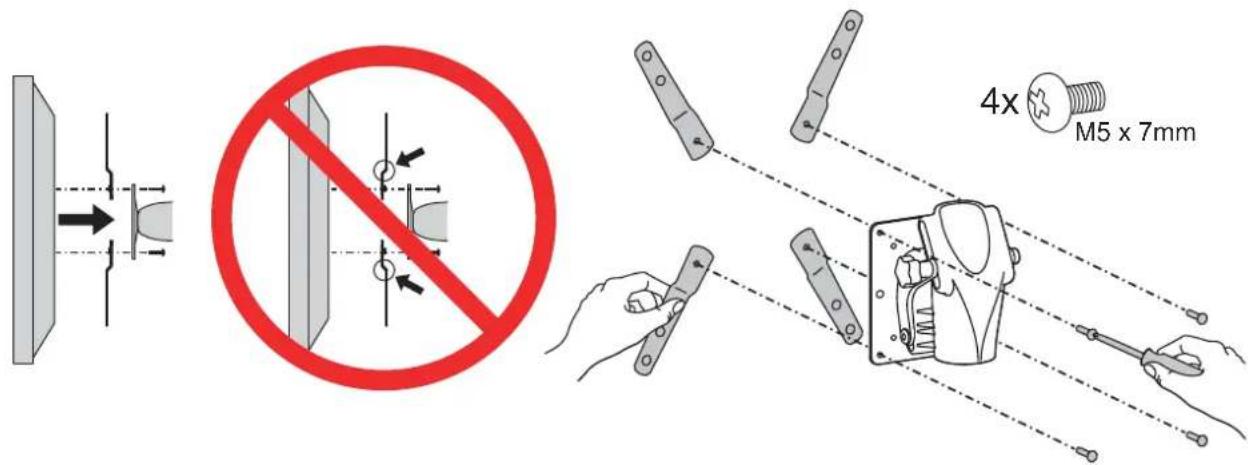
4x M5 x 7mm3b Mount Type B, C, or D TV/Monitor to Arm
text_image
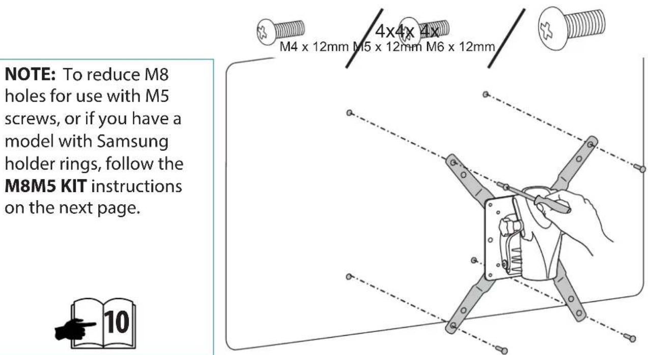
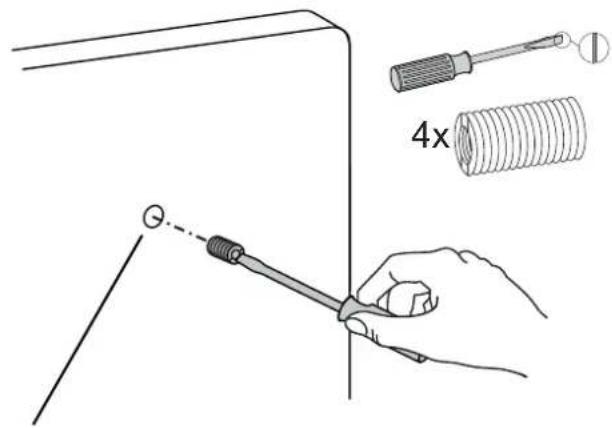
NOTE: To reduce M8 holes for use with M5 screws, or if you have a model with Samsung holder rings, follow the M8M5 KIT instructions on the next page. 10 4x4x 4x M4 x 12mm M5 x 12mm M6 x 12mmM8M5 KIT Instructions
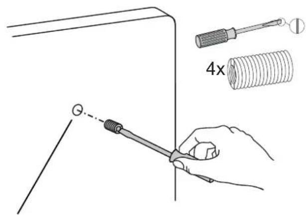
NOTE: Follow this step only if your TV/monitor has M8 holes which need to be reduced to M5.
Install M8M5 reducer bushing to TV/Monitor and use M5 x 20 mm monitor screws to secure.
text_image
4xTV/Monitor Mounting M8 size hole
text_image
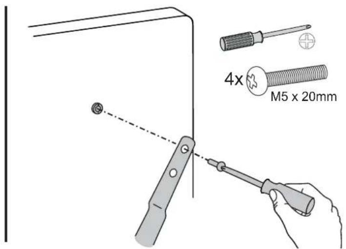
4x M5 x 20mmNOTE: Follow this step only for Samsung models using the holder ring.
Install M8M5 reducer bushing to TV/Monitor then use M5 x 20 mm monitor screws and Samsung holder ring to secure.
text_image
4xTV/Monitor Mounting M8 size hole
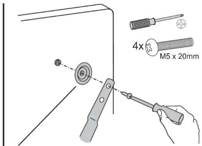
text_image
4x M5 x 20mmHolder Ring (Not included *Samsung Only)

natural_image
Line drawing of a robotic arm interacting with a device, showing a green arrow indicating motion (no text or symbols present)5

Adjustment Step
Important! You will need to adjust this product after installation is complete. Make sure all your equipment is properly installed on the product before attempting adjustments. This product should move smoothly and easily through the full range of motion and stay where you set it. If movements are too easy or difficult or if product does not stay in desired positions, follow the adjustment instructions to create smooth and easy movements. Depending on your product and the adjustment, it may take many turns to notice a difference. Any time equipment is added or removed from this product, resulting in a change in the weight of the mounted load, you should repeat these adjustment steps to ensure safe and optimum operation.
a
Tilt – Forward and Backward
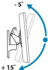
text_image
- 5° + 15°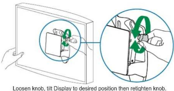
text_image
Loosen knob, tilt Display to desired position then retighten knob.
Pan - Side-to-side
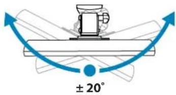
text_image
± 20°
Increase Friction
If this product moves too easily, then you'll need to increase friction:
Decrease Friction
If this product is too difficult to move, then you'll need to decrease friction:

text_image
Diagram illustrating a mechanical device with two circular insets showing positive and negative rotation indicators, likely illustrating a mechanical or electrical setup.Set Your Workstation to Work For YOU!

text_image
≥20" 508mmLearn more about ergonomic computer use at: www.computingcomfort.org
Height Position top of screen slightly below eye level.
Position keyboard at about elbow height with wrists flat.
Distance Position screen an arm's length from face—at least 20" (508mm).
Position keyboard close enough to create a 90° angle in elbow.
Angle Tilt screen to eliminate glare.
Tilt the keyboard back 10° so that your wrists remain flat.
To Reduce Fatigue
Breathe - Breathe deeply through your nose.
Blink - Blink often to avoid dry eyes.
Break • 2 to 3 minutes every 20 minutes
• 15 to 20 minutes every 2 hours.
For Warranty visit: www.ergotron.com/warranty
For Service visit: www.ergotron.com
For local customer care phone numbers visit: http://contact.ergotron.com
NOTE: When contacting customer service, reference the serial number.
ergotron®
www.ergotron.com | USA: 1-800-888-8458 | Europe: +31 (0)33-45 45 600 | China: 400-120-3051 | Japan: japansupport@ergotron.com
© 2014 Ergotron, Inc. All rights reserved.
While Ergotron, Inc. makes every effort to provide accurate and complete information on the installation and use of its products, it will not be held liable for any editorial errors or omissions (including those made in the process of translation from English to another language), or for incidental, special or consequential damages of any nature resulting from furnishing this instruction and performance of equipment in connection with this instruction. Ergotron, Inc. reserves the right to make changes in the product design and/or product documentation without notification to its users. For the most current product information, or to know if this document is available in languages other than those herein, please contact Ergotron. No part of this publication may be reproduced, stored in a retrieval system, or transmitted in any form or by any means, electronic, mechanical, photocopying, recording or otherwise without the prior written consent of Ergotron, Inc., 1181 Trapp Road, Eagan, Minnesota, S5121, USA Patents Pending and Patented U.S. & Foreign. Ergotron is a registered trademark of Ergotron, Inc.