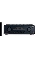
TA-FE570 - Receiver SONY - Free user manual and instructions
Find the device manual for free TA-FE570 SONY in PDF.


| Product type | Integrated stereo receiver |
| Brand | Sony |
| Model | TA-FE570 |
| Output power | 50 W per channel into 8 ohms (RMS) |
| Speaker impedance | 4 to 16 ohms |
| Total harmonic distortion | ≤ 0.05% |
| Signal-to-noise ratio | ≥ 85 dB |
| Dimensions (W × H × D) | 430 × 135 × 320 mm |
| Weight | 8.0 kg |
| Power supply | Mains 230 V AC, 50 Hz |
| Power consumption | 200 W |
| Main functions | Amplifier, FM/AM tuner, input selector, tone control (bass/treble), subsonic filter, loudness, tape deck compatible |
| Audio inputs | Phono (MM), CD, Tuner, Aux, Tape 1/2 |
| Audio outputs | Speakers A/B, headphones, Tape rec, Pre-out (subwoofer) |
| Adjustments | Balance, bass, treble, loudness, subsonic filter |
| Care and cleaning | Clean with a soft, dry cloth. Do not use solvents or abrasive products. |
| Safety | Disconnect before cleaning. Do not expose to moisture or heat sources. Use in a well-ventilated area. |
| Spare parts and repairability | Available through Sony authorized service centers. Some parts can be ordered online. |
| General information | User manual available for download. Serial number located on the rear plate. |
Frequently Asked Questions - TA-FE570 SONY
User questions about TA-FE570 SONY
0 question about this device. Answer the ones you know or ask your own.
Ask a new question about this device
Download the instructions for your Receiver in PDF format for free! Find your manual TA-FE570 - SONY and take your electronic device back in hand. On this page are published all the documents necessary for the use of your device. TA-FE570 by SONY.
USER MANUAL TA-FE570 SONY
Integrated Stereo Amplifier
Operating Instructions GB
Mode d'emploi FR
To avoid electrical shock, do not open the cabinet. Refer servicing to qualified personnel only.
Do not install the appliance in a confined space, such as a bookcase or build-in cabinet.
Install this system so that the power cord can be unplugged from the wall socket immediately in the event of trouble.
To prevent fire, do not Cover the ventilation of the apparatus with news papers, table-cloths, curtains, etc. And don't place lighted candles on the apparatus.
To prevent fire or shock hazard, do not place objects filled with liquids, such as vases, on the apparatus.

Don't throw a battery, dispose it as the injurious wastes.
Precautions
On safety
- Do not disassemble the cabinet as this may result in an electrical shock. Refer servicing to qualified personnel only.
- Should any solid object or liquid fall into the cabinet, unplug the amplifier and have it checked by qualified personnel before operating it any further.
On power sources
- Before operating the amplifier, check that the operating voltage of the amplifier is identical with your local power supply. The operating voltage is indicated on the nameplate at the rear of the amplifier.
- The unit is not disconnected from the AC power source (mains) as long as it is connected to the wall outlet, even if the unit itself has been turned off.
- If you are not going to use the amplifier for a long time, be sure to disconnect the amplifier from the wall outlet. To disconnect the AC power cord (mains lead), grasp the plug itself; never pull the cord.
- AC power cord must be changed only at the qualified service shop.
On placement
- Place the amplifier in a location with adequate ventilation to prevent heat built-up and prolong the life of the amplifier.
- Do not place the amplifier near heat sources, or in a place subject to direct sunlight, excessive dust or mechanical shock.
- Do not place anything on top of the cabinet that might block the ventilation holes and cause malfunctions.
On operation
Before connecting other components, be sure to turn off and unplug the amplifier.
On cleaning the amplifier
Clean the cabinet, panel and controls with a soft cloth slightly moistened with a mild detergent solution. Do not use any type of abrasive pad, scouring powder or solvent such as alcohol or benzine.
On the prevention of howling
Do the following:
– lower the volume.
- keep the turntable as far from the speakers as possible.
– use commercially available audio insulators on the bottom of the turntable.
- keep the microphone away from the speakers during use.
For further protection against howling, set the speakers or turntable on top of a heavy wooden board or concrete slab.
If you have any questions or problems concerning your amplifier, please consult your nearest Sony dealer.
About This Manual
The instructions in this manual are for models TA-FE570 and TA-FE370. Check your model number by looking at the rear panel of your amplifier. The TA-FE570 is the model used for illustration purposes unless stated otherwise.
Any difference in operation is clearly indicated in the text, for example, “TA-FE570 only.”
Type of differences
| Feature FE570 FE370 |
| EON reception ● |
| Tape monitor function ● |
| Switched AC outlets ●* ●* |
* Except for U.K. model.
Tip
Instructions in this manual describe the controls on the amplifier.
For details on the remote buttons control, see
"Remote button descriptions" on page 11.
Table of Contents
Parts Identification
Main unit 4
Getting Started
Unpacking 5
Hookup overview 5
Audio component hookups...... 6
Speaker system hookups 7
Mains lead hookups 7
Basic Operations
Listening to the music 8
Recording 9
Additional Information
Troubleshooting.... 10
Specifications 10
Remote button descriptions ..... 11
Parts Identification
The items are arranged in alphabetical order.
Refer to the pages indicated in parentheses () for details.
Main unit
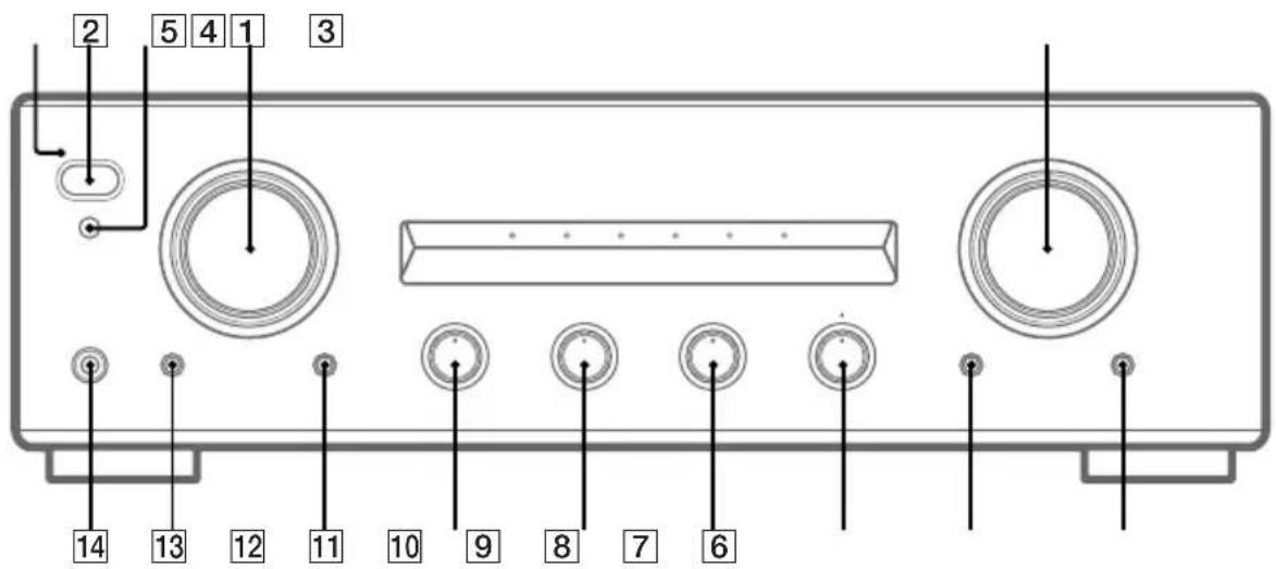
BALANCE 8 (8)
BASS 10 (8)
EON LINK (TA-FE570 only) 13 (8)
INPUT SELECTOR 4 (8, 9)
LOUDNESS 6 (8)
PHONES jack 14 (8)
SOURCE DIRECT 7 (8)
SPEAKERS selector 11 (8)
STANDBY indicator 1
TAPE1 MONITOR (TA-FE570 only) 12 (9)
TREBLE 9 (8)
VOLUME control 5 (8)
I/⏻ (power) 2 (8, 9)
R (remote control sensor) 3 (5)
Getting Started
Unpacking
Check that you have received the following supplied items:
- Remote commander (remote) RM-S325 (1)
- Sony batteries R6 (size-AA) (2)
Inserting batteries into the remote
Insert two R6 (size-AA) batteries, matching the + and - on the batteries with the markings inside the battery compartment. When using the remote, point it at the remote control sensor on the amplifier.

natural_image
Diagram of a battery pack with a switch inserted into a housing (no text or symbols)Tip
With normal use, the batteries should last for about 6 months. When the remote no longer operates the amplifier, replace all the batteries.
Notes
- Do not leave the remote near an extremely hot or humid place.
- Do not drop any foreign object into the remote casing, particularly when replacing the batteries.
- Do not expose the remote sensor to direct sunlight or lighting equipment. Doing so may cause a malfunction.
- If you don't use the remote for an extended period of time, remove the batteries to avoid possible damage from battery leakage and corrosion.
Hookup overview
The amplifier allows you to connect and control the following audio components. Follow the hookup procedure indicated for each component that you want to connect.

flowchart
graph TD
    A["DAT deck"] --> D["Speaker (L) Speaker (R)"]
    B["Tape deck Tuner"] --> D
    C["MD deck Turntable CD player"] --> D
    E["Speaker (L) Speaker (R)"] --> D
Before you get started
- Turn off the power to all components before making any connections.
- Do not connect the mains leads of the various components until all connections are completed.
- Use the audio connecting cords supplied with each component for hooking up with the amplifier. Purchase and use optionally available cords as required.
- Be sure to make connections firmly to prevent hum and noise.
- When connecting an audio connecting cord, be sure to match the R (right) and L (left) jacks of the amplifier to the R and L jacks on the other components.
Audio component hookups
Overview
Here you learn how to connect your audio components to the amplifier.
What cords will I need?
Audio connecting cord (not supplied) (2 for each tape deck, DAT deck, or MD deck; 1 for other components)

Hookups
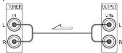
The arrow indicates signal flow.
Note
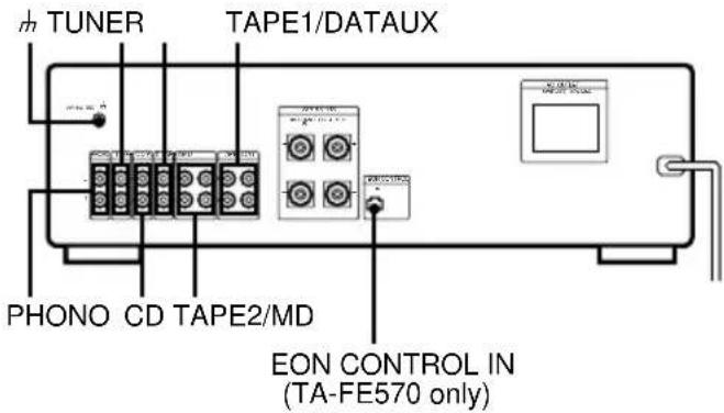
The jacks on the TA-FE570 are shown in the following illustrations.
CD player

flowchart
graph LR
    A["CD"] -->|L| B["IN"]
    A -->|R| C["R"]
    D["OUTPUT"] -->|L| E["LINE"]
    D -->|R| F["R"]
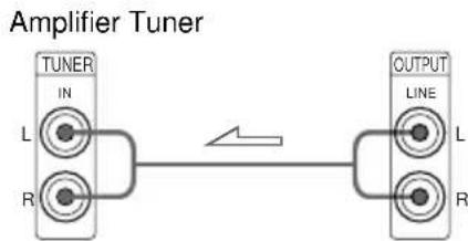
Tuner
flowchart
graph LR
    A["TUNER IN"] --> B["Line L"]
    C["OUTPUT LINE"] --> D["Line L"]
    A --> E["R"]
    C --> F["R"]
Tape deck, DAT deck, or MD deck

flowchart
graph LR
    A["TAPE1/DAT"] -->|OUT IN| B["OUTPUT LINE"]
    A -->|R| C["OUTPUT LINE"]
    B -->|L| D["INPUT LINE"]
    B -->|R| E["INPUT LINE"]
Use the configuration above to connect the OUTPUT and INPUT jacks of:
- a tape deck or DAT deck to the TAPE1/DAT jacks.
- a tape deck or MD deck to the TAPE2/MD jacks.
Turntable

Note
To prevent hum, connect the earth lead to SIGNAL GND ( ) on the amplifier.
EON CONTROL (TA-FE570 only)

flowchart
graph TD
    A["EON CONTROL"] -->|IN| B["In"]
    C["EON CONTROL"] -->|OUT| D["Out"]
If your tuner is equipped with an EON CONTROL OUT terminal, connect it to the EON CONTROL IN terminal on the amplifier to allow use of the EON (Enhanced Other Networks) function of the RDS (Radio Data System) (see page 8).
Speaker system hookups
Overview
Here you learn how to connect speakers to the amplifier. Before connecting, remove the caps from the speaker terminals.

What cords will I need?
Speaker cord (not supplied) (1 for each speaker)

Twist the stripped ends of the cord about 15 mm. Be sure to match the speaker cord to the appropriate terminal on the components: + to + and - to -. If the cords are reversed, the sound will be distorted and will lack bass.
Hookups

natural_image
Diagram showing two cylindrical objects with positive and negative charges, connected by curved lines (no text or symbols)Mains lead hookups

Connecting the mains lead
Connect the mains lead from this amplifier and from your audio/video components to wall outlets.
Tip
You can power other components through AC OUTLET on the amplifier (except for U.K. model). By connecting other audio components to AC OUTLET on the amplifier, you can supply power to the connected components through the amplifier and turn them all on or off when you turn the amplifier on or off.
Caution
Make sure that the total power consumption of all components connected to the outlets on the amplifier does not exceed 100 watts. Do not connect electrical home appliances such as an electric iron, fan, TV, or other high-wattage appliances to these outlets.
Note
Separate the mains lead, audio connecting cords and speaker cords. Noise or sound deterioration may occur when audio connecting cords are in contact with the mains lead, or when the mains lead or speaker cords are placed near the tuner's loop aerial or aerial wire.
Basic Operations
Listening to the music
1 Press I/⏻ to turn on the amplifier and turn VOLUME fully anticlockwise to prevent damaging the speakers with excessive output.
2 Turn on the programme source you want to listen to.
3 Turn INPUT SELECTOR to select the respective programme source.
To listen to a Select
| Record PHONO |
| Radio broadcast TUNER |
| Compact disc CD |
| Source connected to AUX AUX |
| Source connected to: - TAPE1/DAT TAPE1/DAT - TAPE2/MD TAPE2/MD |
4 Start the programme source.
5 Adjust the volume by turning VOLUME.
To Press or turn
| Adjust the bass BASS |
| Adjust the treble TREBLE |
| Adjust the balance BALANCE |
| Reinforce the bass and treble LOUDNESS at low listening level |
Tips
- If I / is pressed down, you can turn the amplifier on and off by pressing I / on the remote.
- To listen through the headphones, connect the headphones to PHONES and set SPEAKERS to OFF.
- To listen directly to the input signal, press SOURCE DIRECT so that the indicator lights up. Since the circuits of TONE controls, BALANCE control, and LOUDNESS button are bypassed, you cannot adjust bass, treble, the balance, reinforce the bass and treble while listening to a source directly.
Note
Avoid high speaker output at which the sound is distorted. High-frequency distortion may damage the tweeters.
To receive the Enhanced Other Networks (EON) programmes
(TA-FE570 only)
“Enhanced Other Networks (EON)” is one of the convenient RDS services. This allows the unit to automatically switch to a programme type of your choice when one starts in your broadcast area.
When your amplifier is connected to a Sony tuner with the EON CONTROL system, the amplifier switches to any EON programme that is broadcast in your EON area, and switches back to the last selected programme source when the programme ends.
1 Make sure that the amplifier and the tuner are connected through the EON CONTROL terminals (see page 6).
2 Press EON LINK so that the indicator lights up.
Whenever an EON programme starts on the radio frequency that your tuner is set to, you will receive it.
To cancel EON reception
Press EON LINK again so that the indicator goes off.
Notes
- If you select another programme source while receiving an EON programme, EON reception ends. However, as long as the EON LINK indicator lights up, you can receive EON programmes automatically.
- Make sure to cancel EON reception before starting to record since an EON programme may interfere with your recording.
- If you activate the Tape Monitor function (see page 9) while the EON LINK indicator is lit, the indicator goes off and you cannot receive EON programmes. If this happens, deactivate the Tape Monitor function so that the indicator lights up again.
Recording
1 Press I/⏻ to turn on the amplifier.
2 Turn on the programme source you want to record.
3 Turn INPUT SELECTOR to select the programme source you want to record.
To record a Select
| Record PHONO |
| Radio broadcast TUNER |
| Compact disc CD |
| Source connected to AUX AUX |
| Source connected to: - TAPE1/DAT TAPE1/DAT - TAPE2/MD TAPE2/MD |
4 Prepare the recording component for recording, then start recording.
5 Start playing the programme source.
Tips
- You can record the same source on two recording components at the same time
- You can monitor the recorded sound if the tape deck you are recording on has separate playback and recording heads (Tape Monitor function) (TA-FE570 only).
To monitor the sound, press TAPE1 MONITOR. Note that you can monitor the only sound being recorded from the TAPE1/DAT jacks.
Additional Information
Troubleshooting
If you experience any of the following difficulties while using the amplifier, use this troubleshooting guide to help you remedy the problem. Should any problem persist, consult your nearest Sony dealer.
No sound output.
- Connect the audio connecting cords firmly.
- Connect the amplifier and other audio components correctly.
- Turn INPUT SELECTOR to the appropriate programme source.
- Set SPEAKERS to ON.
No audio from one channel or unbalanced speaker output.
- Turn BALANCE to adjust the balance.
- Check the speaker and input connections of silent channel.
Weak bass or treble.
- Adjust the TONE controls.
- Change speaker positions or room conditions to eliminate obstructions in sound path.
Distorted sound.
- Improperly selected input signal.
- Insufficient input capacity of speakers. Lower the volume.
Lack of bass or ambiguity in instrument positions.
- Speaker cord and terminal polarity are reversed. Reconnect the cords with correct polarity.
Hum or noise.
- Ground the turntable system (see page 6).
- Connect the audio connecting cords firmly.
- The amplifier is picking up interference from a TV set. Move the amplifier away from the TV set or turn the TV set off.
The remote does not function.
- Remove any obstructions between the remote control sensor on the amplifier and the remote.
- Point the remote towards the remote sensor on the front of the amplifier.
- The remote is too far from the amplifier. Move closer to the amplifier.
- Replace the batteries in the remote.
Sudden loss of audio.
- Check if a short-circuit has occurred. Turn off the amplifier and check the connected components and speakers.
Specifications
Amplifier section
DIN power output
TA-FE570: 110 W + 110 W (4 ohms at 1 kHz) TA-FE370: 70 W + 70 W (4 ohms at 1 kHz)
Frequency response
PHONO (20 Hz - 20 kHz):RIAA equalization curve ±1.0 dB
TUNER, CD, AUX, TAPE1/DAT, TAPE2/MD: 7 Hz - 70 kHz ^+0_-3 dB
S/N (network A)
PHONO: 80 dB
TUNER, CD, AUX, TAPE1/DAT, TAPE2/MD: 105 dB
Output voltage/impedance
RECOUT: 200 mV, 1 kilohm
PHONES: 5 mW (at 8 ohms)
Speakers impedance 4 - 16 ohms
Damping factor 80 (8 ohms, 1 kHz)
General
System
Power amplifier with all stages directly coupled
Preamplifier: Low-noise, equalizer amplifier
Power requirements 230 V AC, 50/60 Hz
Power consumption
TA-FE570: 190 W
TA-FE370: 160 W
0.6 W
(In standby mode)
Dimensions (approx.) (w/h/d)
430 x 135 x 310 mm
incl. projecting parts and controls
Mass (approx.)
TA-FE570: 6.5 kg
TA-FE370: 5.5 kg
Supplied accessories
Remote commander (remote) RM-S325 (1)
Sony batteries R6 (size-AA) (2)
Design and specifications are subject to change without notice.
Remote button descriptions
You can use the supplied remote to control other Sony audio components equipped with the R (remote control sensor) mark.
| Remote button(s) | Component | Function |
| I/○ | Amplifier Turns the amplifier on and off. |
FUNCTION
CD Amplifier Selects input signals from the CD jacks.
TUNER Amplifier Selects input signals from the TUNER jacks.
PHONO Amplifier Selects input signals from the PHONO jacks.
TAPE1/DAT Amplifier Selects input signals from the TAPE1/DAT jacks.
TAPE2/MD Amplifier Selects input signals from the TAPE2/MD jacks.
AUX Amplifier Selects input signals from the AUX jacks.
TUNER
PRESET +/- Tuner Scans and selects preset stations.
CD
▶ CD player Starts playback.
CD player Pauses playback.
■ CD player Stops playback.
◀◀/▶▶ CD player Locates tracks (AMS*).
D.SKIP CD player Skips a disc (for CD player equipped with a multi-disc changer).
MD
▶ MD deck Starts playback.
II MD deck Pauses playback.
■ MD deck Stops playback.
|◀◀/▶▶ MD deck Locates tracks.
TAPE DECK A/B
◀/▶ Deck A or B Starts playback.
■ Deck A or B Stops all tape operations.
◀◀/▶▶ Deck A or B Fast-forwards or rewinds the tape.
VOL +/- Amplifier Controls the volume.
AVERTISSEMENT
Appareil principal 4
Préparatifs
Déballage 5
Raccordements 5
Commande VOLUME 5 (8)
EON LINK (TA-FE570 seulement) 13 (8)
natural_image
Diagram of a battery pack with two terminals and a switch, showing internal components (no text or symbols)Conseil
Raccordements
Tuner
Amplificateur Tuner
flowchart
graph LR
    A["TUNER IN"] --> B["Inverter"]
    B --> C["R"]
    C --> D["Output LINE L R"]
    style A fill:#f9f,stroke:#333
    style D fill:#bbf,stroke:#333
Remarque
natural_image
Diagram showing two cylindrical objects with positive and negative charges, connected by curved lines and arrows indicating motion (no text or symbols)Dimensions (approx.) (l/h/p)
430 x 135 x 310 mm
natural_image
Diagram of a battery pack with two terminals and a switch, showing internal components (no text or symbols)Tip
chemical
Diagram of a wireless signal transmission line with two types of connectors labeled in English: Weiβ (L) and Rot (R).Anschluß
flowchart
graph LR
    A["CD"] -->|L R| B["OUTPUT"]
    B -->|L R| A
Tuner
Verstärker Tuner

flowchart
graph LR
    A["TUNER IN"] --> B["IN"]
    B --> C["R"]
    C --> D["OUTPUT LINE L R"]
    D -->|Arrow| B
Hinweis
natural_image
Diagram of two cylindrical objects with curved lines and directional arrows, no text or symbols presentNetzanschluß

Vorbereitung
PHONES: 5 mW (an 8 Ohm)
natural_image
Diagram of a battery pack with a switch and connector, no text or symbols presentSugerencia
chemical
Diagram of two types of resistors with labeled terminals: Blanca (Izq.) and Roja (Der.), each connected to a terminal resistor.Conexiones
Nota
natural_image
Diagram of two cylindrical objects with curved and straight lines, no text or symbols presentTA-FE570: 110 W + 110 W (4 ohm a 1 kHz) TA-FE370: 70 W + 70 W (4 ohm a 1 kHz)
PHONES: 5 mW (a 8 ohm)
- Integrated Stereo Amplifier
- Precautions
- On safety
- On power sources
- On placement
- On operation
- On cleaning the amplifier
- On the prevention of howling
- About This Manual
- Tip
- Table of Contents
- Parts Identification
- Getting Started
- Basic Operations
- Additional Information
- Main unit
- Unpacking
- Inserting batteries into the remote
- Notes
- Hookup overview
- Before you get started
- Audio component hookups
- Overview
- What cords will I need?
- Hookups
- Note
- CD player
- Tuner
- Tape deck, DAT deck, or MD deck
- Turntable
- EON CONTROL (TA-FE570 only)
- Speaker system hookups
- Mains lead hookups
- Connecting the mains lead
- Caution
- Listening to the music
- Tips
- To receive the Enhanced Other Networks (EON) programmes
- (TA-FE570 only)
- To cancel EON reception
- Recording
- Troubleshooting
- No sound output.
- No audio from one channel or unbalanced speaker output.
- Weak bass or treble.
- Distorted sound.
- Lack of bass or ambiguity in instrument positions.
- Hum or noise.
- The remote does not function.
- Sudden loss of audio.
- Specifications
- Amplifier section
- DIN power output
- Frequency response
- S/N (network A)
- Output voltage/impedance
- General
- System
- Power consumption
- Dimensions (approx.) (w/h/d)
- Mass (approx.)
- Supplied accessories
- Remote button descriptions
- FUNCTION
- CD
- MD
- TAPE DECK A/B
- AVERTISSEMENT
- Préparatifs
- Conseil
- Raccordements
- Remarque
- Dimensions (approx.) (l/h/p)
- Anschluß
- Hinweis
- Netzanschluß
- Sugerencia
- Conexiones
- Nota
Brand : SONY
Model : TA-FE570
Category : Receiver