
TA-F501ES - Receiver SONY - Free user manual and instructions
Find the device manual for free TA-F501ES SONY in PDF.


| Product Type | Stereo Integrated Amplifier |
| Brand | Sony |
| Model | TA-F501ES |
| Dimensions (W x D x H) | 430 x 380 x 150 mm |
| Weight | 12.5 kg |
| Output Power | 2 x 100 W (8 ohms, 20 Hz – 20 kHz, 0.008% THD) |
| Frequency Response | 5 Hz – 100 kHz (+0/-3 dB) |
| Total Harmonic Distortion | < 0.008% (20 Hz – 20 kHz) |
| Signal-to-Noise Ratio | 100 dB (line input) |
| Input Impedance | 50 kohms (line), 47 kohms (phono MM) |
| Inputs | Phono (MM), CD, Tuner, Aux, Tape 1/2 |
| Outputs | Speakers A/B, pre-out, headphone output (6.35 mm) |
| Main Functions | Volume, Balance, Bass, Treble, Loudness, Direct, Subsonic Filter, Monitor |
| Remote Control | Not included (compatible with optional RM-xxxx) |
| Power Consumption | 250 W (max) |
| Power Supply | 220-230 V AC, 50/60 Hz |
| Maintenance and Cleaning | Disconnect the device before cleaning. Use a soft, dry cloth. Do not use solvents or abrasive products. |
| Safety | Do not expose to moisture, heat sources, or vibrations. Ensure adequate ventilation around the unit. |
| Spare Parts and Repairability | Contact a Sony authorized service center. Use only genuine replacement parts. |
| General Information | Integrated amplifier from the ES series (Essential Series) offering high sound quality and robust construction. |
Frequently Asked Questions - TA-F501ES SONY
User questions about TA-F501ES SONY
0 question about this device. Answer the ones you know or ask your own.
Ask a new question about this device
Download the instructions for your Receiver in PDF format for free! Find your manual TA-F501ES - SONY and take your electronic device back in hand. On this page are published all the documents necessary for the use of your device. TA-F501ES by SONY.
USER MANUAL TA-F501ES SONY
Integrated Stereo Amplifier
Operating Instructions GB
Mode d'emploi FR
To reduce the risk of fire or electric shock, do not expose this apparatus to rain or moisture.
To prevent fire, do not cover the ventilation of the apparatus with news papers, table-cloths, curtains, etc. And don't place lighted candles on the apparatus.
To prevent fire or shock hazard, do not place objects filled with liquids, such as vases, on the apparatus.
Do not install the appliance in a confined space, such as a bookcase or built-in cabinet.
Install this system so that the power cord can be unplugged from the wall socket immediately in the event of trouble.
CAUTION
Danger of explosion if battery is incorrectly replaced. Replace only with the same or equivalent type recommended by the manufacturer. Discard used batteries according to the manufacturer's instructions.

Don't throw away the battery with general house waste, dispose of it correctly as chemical waste.
Batteries or batteries installed apparatus shall not be exposed to excessive heat such as sunshine, fire or the like.
NOTICE FOR THE CUSTOMERS IN THE UNITED KINGDOM
A moulded plug complying with BS1363 is fitted to this equipment for your safety and convenience.
Should the fuse in the plug supplied need to be replaced, a fuse of the same rating as the supplied one and approved by ASTA or BSI to BS1362, (i.e., marked with or mark) must be used.
If the plug supplied with this equipment has a detachable fuse cover, be sure to attach the fuse cover after you change the fuse. Never use the plug without the fuse cover.
If you should lose the fuse cover, please contact your nearest Sony service station.
Disposal of Old Electrical & Electronic Equipment (Applicable in the European Union and other European countries with separate collection systems)

This symbol on the product or on its packaging indicates that this product shall not be treated as household waste. Instead it shall be handed over to the applicable collection point for the recycling of electrical and electronic equipment. By ensuring this product is disposed of correctly, you will help prevent potential negative consequences for the environment and human health, which could otherwise be caused by inappropriate waste handling of this product. The recycling of materials will help to conserve natural resources. For more detailed information about recycling of this product, please contact your local Civic Office, your household waste disposal service or the shop where you purchased the product.

The manufacturer of this product is Sony Corporation, 1-7-1 Konan Minato-ku Tokyo, 108-0075 Japan. The Authorized Representative for EMC and product safety is Sony Deutschland GmbH, Hedelfinger Strasse 61, 70327 Stuttgart, Germany. For any service or guarantee matters please refer to the addresses given in separate service or guarantee documents.
About this manual
- The instructions in this manual are for model TA-F501ES. Check your model number by looking at the lower right corner of the front panel.
- The instructions in this manual describe the controls on the supplied remote. You can also use the controls on the amplifier if they have the same or similar names as those on the remote.
This amplifier incorporates Dolby* Digital and DTS**.
* Manufactured under license from Dolby Laboratories.
“Dolby” and the double-D symbol are trademarks of Dolby Laboratories.
** “DTS” and “DTS 2.0” are trademarks of DTS, Inc.
Table of contents
Getting Started
Unpacking 4
Connecting speakers ....5
Connecting components with analog audio input/output jacks ....6
Connecting components with digital audio input/output jacks ....7
Connecting the AC power cord (mains lead) 8
Preparing the remote 9
Location of Parts and Operation
Front panel 10
Rear panel 11
Remote commander ....12
Configuration
Calibrating the appropriate speaker settings automatically (AUTO CALIBRATION)....13
Settings for the amplifier ....16
Clearing the amplifier's memory ....18
Additional Information
Precautions ......19
Troubleshooting 20
Specifications ......21
Index 23
Getting Started
Unpacking
Check that you received the following items:
- Operating Instructions (this manual)
- Optimizer microphone ECM-AC1 (1)
• AC power cord (mains lead) (1) - Remote commander RM-AAU012 (1)
If any item is missing, please consult your nearest Sony dealer.
Audio connecting cords, digital connecting cords, speaker cords are not supplied with this amplifier. Please purchase them separately.
Notes on connections
- Turn off the power to all components before making any connections.
- Do not connect the AC power cord (mains lead) until all of the connections are completed.
- Be sure to insert all plugs firmly to avoid hum and noise.
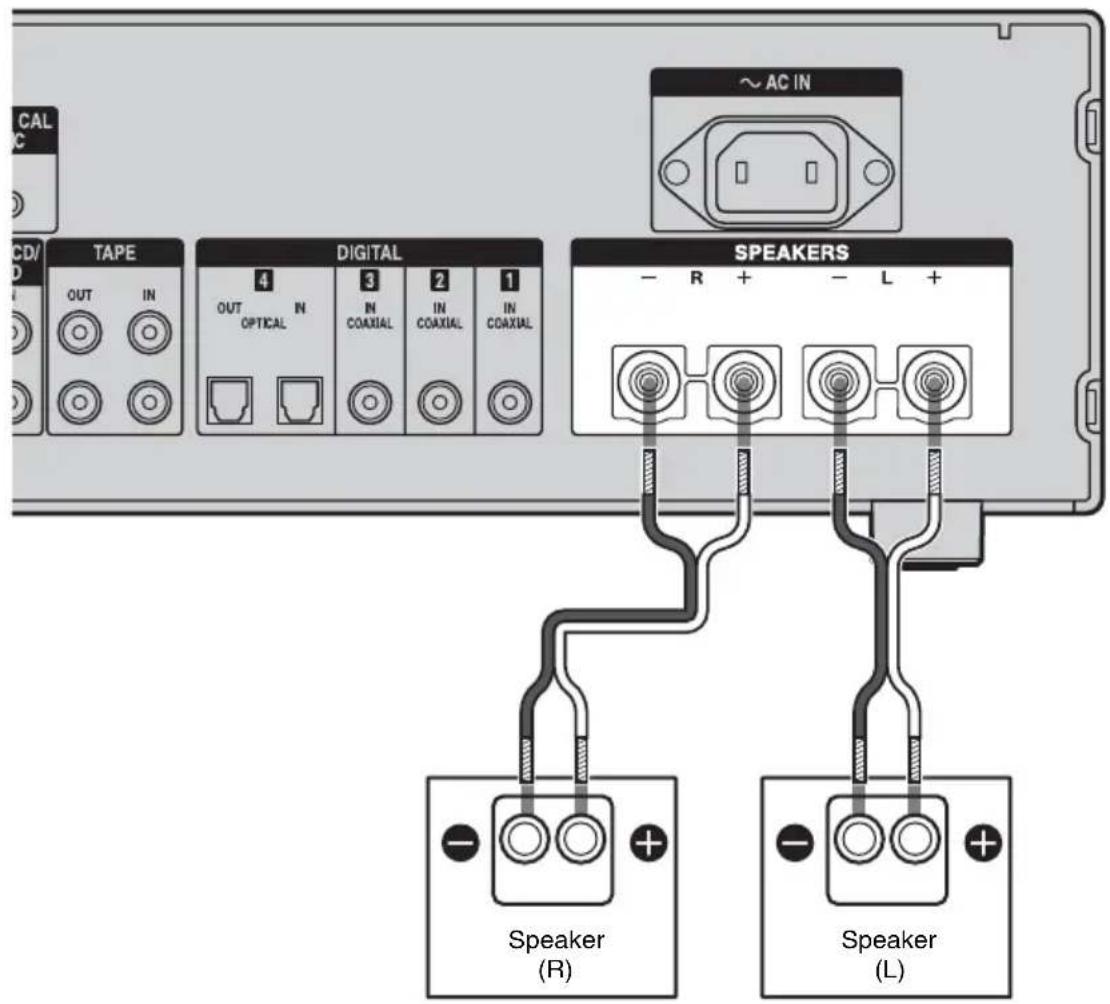
Connecting speakers
Connect your speakers to the amplifier.
Use a speaker cord (not supplied) to connect to the speaker terminals.
Speaker cord (not supplied)

Notes on speaker connections
Connect the left speaker to the SPEAKERS L terminals and the right speaker to the SPEAKERS R terminals.
Be sure to connect the speaker cords between the speakers and the amplifier with the same polarities (plus (+) to plus (+), minus (−) to minus (−)).
By paying attention to the color or mark of the speaker cord to be connected to the plus (+) or minus (−) connector, you can always be sure of connecting the cord correctly without mistaking plus or minus.
Connecting components with analog audio input/output jacks
You can connect a component with analog audio jacks, such as a Super Audio CD player or CD player, etc. to this amplifier.
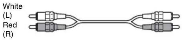
Use an audio cord (not supplied) to connect a component to the analog audio jacks.
Connect the white plug to the L jack and the red plug to the R jack.
Audio cord (not supplied)

Note
If your turntable has a ground (earth) wire, connect it to the () SIGNAL GND terminal to avoid a humming noise.
Connecting components with digital audio input/output jacks
Connecting to the COAXIAL jack Connecting to the OPTICAL jack
You can connect a component with coaxial digital output jacks to this amplifier.
Use a coaxial digital cord (not supplied) to connect a component to the COAXIAL jacks (DIGITAL 1 to 3).
Coaxial digital cord (not supplied)

You can connect a component with optical digital output jacks to this amplifier.
Use an optical digital cord (not supplied) to connect a component to the OPTICAL jacks (DIGITAL 4).
When connecting optical digital cords, insert the plugs straight in until they click into place.
Optical digital cord (not supplied)


Notes
- When DIGITAL 1, 2, or 3 is selected, the selected input signal is output from the DIGITAL 4 OUT jack. When DIGITAL 4 or analog input is selected, no signal is output from the DIGITAL 4 OUT jack.
- Only the audio signal of the CD player is output from the DIGITAL COAXIAL OUT jack. However, the audio signal of a Super Audio CD player is not output from the DIGITAL COAXIAL OUT jack at all.
Tip
All the digital audio jacks are compatible with 32 kHz, 44.1 kHz, and 48 kHz sampling frequencies.
Connecting the AC power cord (mains lead)
Connect the supplied AC power cord (mains lead) to the AC IN terminal on the amplifier, then connect the AC power cord (mains lead) to the wall outlet.

A several space is left between the plug and the rear panel even when the power cord (mains lead) is inserted firmly. The cord is supposed be connected this way. This is not a malfunction.
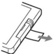
Preparing the remote
Pull out the insulating sheet to allow power to flow from the battery.
The remote already contains a battery.
natural_image
Pure mechanical component diagram without any text, numbers, or symbolsReplacing the battery in the remote
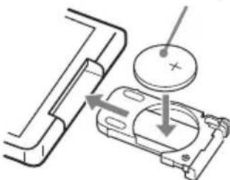
1 Slide out the battery case in the direction of arrow ② by pushing the lock in the direction of arrow ① and then remove the battery from the battery case.
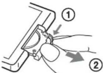
2 Insert a new lithium battery CR2025 with the + side facing up.
A lithium battery CR2025
natural_image
Mechanical assembly diagram showing a pipe fitting and a housing component with a circular element (no text or symbols)3 Slide the battery case back in.
Note
If you do not use the remote for a long period of time, remove the battery to avoid possible damage from battery leakage and corrosion.
Notes on lithium battery
- Keep the lithium battery out of the reach of children. Should the battery be swallowed, immediately consult a doctor.
- Wipe the battery with a dry cloth to assure a good contact.
- Be sure to observe the correct polarity when installing the battery.
- Do not hold the battery with metallic tweezers, otherwise a short-circuit may occur.
Note
Do not expose the remote sensor Rb direct sunlight or lighting apparatus. Doing so may cause a malfunction.
Tip
When the remote can no longer operate the system, replace the battery with a new one.
WARNING
Battery may explode if you mistreated. Do not recharge, disassemble or dispose of in fire.
Front panel

Name Function
1 POWER Press to turn the amplifier on or off.
2 Remote sensor Receives signals from the remote.
3 TONE Turn to adjust the BASS/TREBLE BASS and TREBLE levels.
The level can be adjusted from -10 dB to +10 dB.
4 Display The current status of the selected component or a list of selectable items appears here.
5 INPUT
SELECTOR
Turn to select the input source to play back.
6 VOLUME Turn to adjust the volume level of speakers. The level can be adjusted from -∞ dB to +23 dB.
Name Function
7 MUTING Press to turn off the sound temporarily. Press the button again to restore the sound.
8 PHONES jack Connects to headphones.
Rear panel

1 AUDIO INPUT/OUTPUT section
 | Audio input/output jacks | Connects to a Super Audio CD player, tape deck, MD deck or DAT player, etc (page 6). |
 |
2 AUTO CAL MIC jack
| (B+C2) | Connects to the supplied optimizer microphone for the Auto Calibration function (page 13). |
3 DIGITAL INPUT/OUTPUT section
 | COAXIAL IN jacks | Connects to a DVD player, Super Audio CD player, etc. The |
 | OPTICAL IN/ OUT jack | COAXIAL jacks provide a better quality sound (page 7). |
4 SPEAKERS section
| Connects to speakers(page 5). |
5 SIGNAL GND terminal
| If a turntable has a ground (earth) wire, connect it to this terminal to avoid a humming noise (page 6). |
Remote commander
RM-AAU012

Name Function
| 1DISPLAYON/OFF | Press to turn the display in the display window on and off. |
| 2Inputbuttons | Press one of the buttons to select the component you want to use. |
| 3VOL +/- Press to adjust the volume level of speakers.The level can be adjusted from -∞ dB to +23 dB. | |
| 4BALANCEL/R | Press to adjust the balance between left and right speakers. Both the left and the right balance can be adjusted from 0 dB to +20 dB. The initial setting is 0 dB (center). |
Name Function
| 5Operation buttons for a Sony CD player | You can only operate a Sony CD player using this remote, when you connect it to the this amplifier. ▷ playback■ pause■ stop■◀◀/▶▶I select a track ◀◀◀/▶▶ fast backward/forward |
| 6MUTING Press to turn off the sound temporarily. Press the button again to restore the sound. | |
| 7MENU Press to display the menu for the amplifier (page 16). | |
| 8▲/▼/←/→⊕ | After pressing MENU (7), press ↑/▼/←/→ to select the settings. Then press to enter the selection (page 16). |
| 9LOUDNESS Set the LOUDNESS function to ON to adjust the BASS and TREBLE levels output from the speakers to the optimum settings, based on the volume level.When you set the LOUDNESS function to OFF, the BASS and TREBLE levels will return to the levels that had been adjusted before the LOUDNESS function was set to ON.Initial setting is OFF. | |
| 10BASS/TREBLE +/- | Press to adjust the BASS and TREBLE levels. The level can be adjusted from -10 dB to +10 dB. |
Notes
- The remote command mode of the remote supplied with this amplifier is fixed to CD1 for the connected CD player. Set the remote command mode of the CD player to CD1; otherwise, you cannot operate the CD player using this remote.
- You can adjust the BASS and TREBLE levels manually even when the LOUDNESS function is set to ON. If you adjust the levels manually, the LOUDNESS function will be switched to OFF, automatically.
Configuration
Calibrating the appropriate speaker settings automatically (AUTO CALIBRATION)
The auto calibration function allows you to measure the following:
- Speaker connections
- Speaker distance
- Speaker angle
- Speaker level
• Frequency characteristics
After saving the measurement results, you can confirm the speaker level by pressing BALANCE L/R (page 12). Other measurement results are not displayed, but are set to appropriate settings automatically.
Before you perform auto calibration
Before you perform auto calibration, set up and connect the speakers (page 5).
- The AUTO CAL MIC jack is used for the supplied optimizer microphone only. Do not connect other microphones to this jack. Doing so may damage the amplifier and the microphone.
- During the measurement, the sound that comes out of the speakers is very loud. The volume of the sound cannot be adjusted. Pay attention to the presence of children or to the effect on your neighborhood.
- Perform the measurement in a quiet environment to avoid the effect of noise and get a more accurate measurement.
- If there are any obstacles in the path between the optimizer microphone and the speakers, the measurement cannot be performed correctly. Remove any obstacles from the
measurement area to avoid measurement error.
Notes
- The auto calibration function does not work when headphones are connected to the amplifier.
- Cancel MUTING if it is set to on.

1 Connect the supplied optimizer microphone to the AUTO CAL MIC jack on the rear panel.
2 Set up the optimizer microphone.
Place the optimizer microphone at your listening position. Use a stool or tripod so that the optimizer microphone remains at the same height as your ears. Orient the L end of the optimizer microphone toward the front left speaker and the R end of the optimizer microphone toward the front right speaker.
Note
When you position the optimizer microphone at the center of the two speakers, if the angle between the two speakers is too narrow, the optimizer microphone cannot measure the left and right speakers properly.
Performing the measurement
1 Turn on the amplifier.
2 Press MENU.
3 Press ↓ to display “<2-Auto Calibration>,” then press to enter the menu.
4 Press ↓ to display "CAL TYPE," then press ⓣ to enter the parameter.
5 Press / to select the parameter, then press to enter the selection.
| Calibration type | Explanation |
| ENGINEER Sets the frequency characteristics to a set that matches that of the Sony listening room standard. | |
| FULL FLAT Makes the measurement of frequency from each speaker flat. | |
6 Press ↑ to display "AUTO CAL START?," then press ⓣ to start the measurement.
The measurement starts in five seconds. A countdown appears on the display. While the time is counting down, stand away from the measurement area to avoid measurement error.
7 The measurement starts.
The measurement process will take approximately 10 seconds. Wait until the measurement process completes.
Tip
When special speakers, such as dipole speakers, are used, the measurements may not be performed correctly or auto calibration cannot be performed.
To cancel the measurement
The measurement is cancelled when you change the volume, change the input source, press MUTING, or connect headphones.
Confirming/saving the measurement results
1 Confirm the measurement result.
When the measurement ends, a beep sounds and the measurement result appears on the display.
| Measurement result | Display Explanation | |
| When the measurement process completes properly | COMPLETE | Proceed to step 2. |
| When the measurement process fails | ERROR CODE 3■ | See “When error codes appear” (page 15). |
2 Press / repeatedly to select the item, then press ⏻
| Item Explanation |
| RETRY Re-performs the measurement. |
| SAVE EXIT Saves the measurement results and exits the setting process. |
| WRN CHECK Displays a warning concerning the measurement results. See “When you select “WRN CHECK”” (page 15). |
| EXIT Exits the setting process without saving the measurement results. |
When error codes appear
Try the remedies and re-perform the measurement.
Error code Cause and remedies
| CODE 32 None of the speakers were detected. Make sure that the optimizer microphone is connected properly and re-perform the measurement. If the optimizer microphone is connected properly but the error code appears, the optimizer microphone cable may be damaged or improperly connected. | |
| CODE 33 None of the speakers are connected. | |
| CODE 34 | Speakers are not placed in the proper position. Speakers or an optimizer microphone on the right or left may be placed wrongly. Check the speaker position. |
•CODE 32, 33, 34
1 Remedy the error.
2 Press ⊕.
"RETRY?" appears.
3 Press ↗/↓ to select "YES," then press ⊕
The measurement is restarted from step 7 of “Performing the measurement.”
When you select "WRN CHECK"
If a warning on the measurement result is present, detailed information is displayed.
Press to return to step 1 of "Confirming/saving the measurement results."
Warning code Explanation
| WARNING 40 | Try to perform the measurement in a quiet environment.The measurement has completed.However, the noise level is high.You may be able to perform the auto calibration properly if you try it again, even though the measurement cannot be performed in all environments. |
Warning code Explanation
| WARNING 41 Try to perform the measurement when the environment is quiet enough to allow proper measurement.The sound input from the optimizer microphone is outside the acceptable range. It is louder than the loudest sound that can be measured. |
| WARNING 42 Try to perform the measurement when the environment is quiet enough to allow proper measurement.The volume of the amplifier is out of the acceptable range. |
NO WARNING There is no warning information.
Auto Calibration menu parameters
The initial setting is underlined.
■ AUTO CAL START? (Starts auto calibration)
- MEASUREMENT COUNTDOWN A time countdown appears on the display from five seconds to one second.
- MEASURING TONE Appears while TONE is being measured.
- MEASURING T.S.P. Appears while TSP* is being measured.
- COMPLETE Appears when the measurement process completes successfully. For details on each message, see “Confirming/saving the measurement results” (page 14).
- WARNING CODE [ :4■] Appears if a warning on the measurement result is present. For details on each message, see “Confirming/saving the measurement results” (page 14).
- NO WARNING There is no warning information.
- ERROR CODE [ :3■] Appears when the measurement fails. For details on each message, see “Confirming/saving the measurement results” (page 14).
- RETRY?
Appears to ask you to re-measure or exit without re-measuring when the measurement fails.
- CANCEL
Appears when you cancel the measurement.
* TSP (Time Stretched Pulse)
A TSP signal is a highly precise measuring signal that utilizes impulse energy, measuring a wide band, from low to high, in a short period.
The amount of energy used to measure signals is important to ensure measurement accuracy in a normal indoor environment. Using TSP signals makes it possible to measure signals effectively.
CAL TYPE
(Parameter type)
• ENGINEER
Sets the frequency to one that matches that of the Sony listening room standard.
• FULL FLAT
Makes the measurement of frequency from each speaker flat.
■ EQ CURVE EFFECT
(Activates/deactivates the EQ curve measurement)
• OFF
Deactivates the EQ curve measurement.
• ON
Activates the EQ curve measurement.
After the measurement is completed, this setting is set to ON automatically.
Note
You cannot select this setting before saving the measurement results (factory setting).
Settings for the amplifier
By using the System Settings menus, you can make various adjustments to customize the amplifier.
1 Press MENU.
2 Press ↑ to display "<1-System Settings>," then press ⓣ to enter the menu.
3 Press ↑/↓ repeatedly to display the parameter you want to adjust.
4 Press to enter the parameter.
5 Press ↑/↓ repeatedly to select the setting you want to adjust.
6 Press to enter.
7 Repeat steps 3 to 6 when you want to make other settings.
To return to the menu one level up
Press ←.
To exit the menu
Press MENU.
Note
Some parameters and settings may appear dimmed on the display. This means that they are either unavailable or fixed and unchangeable.
System Settings menu parameters
The initial setting is underlined.
■ DEC. PRIORITY (Digital audio input decoding priority)
Lets you specify the input mode for the digital signal input to the DIGITAL IN jacks.
• A U T O
Automatically switches the input mode between DTS, Dolby Digital, or PCM.
• PCM
PCM signals are given priority (to prevent interruption when playback starts).
Note
When set to “AUTO” and the sound from the digital audio jacks (for a CD, etc.) is interrupted when playback starts, set to “PCM.”
■ DUAL MONO (Bilingual audio selection)
For a bilingual broadcast, you can select the language you want to listen to. This feature only functions for Dolby Digital sources.
- MAIN/SUB Sound of the main language will be output through the left speaker, and sound of the sub language will be output through the right speaker simultaneously.
- MAIN Sound of the main language will be output.
- SUB Sound of the sub language will be output.
- MAIN+SUB Mixed sound of both the main and sub languages will be output.
■ D.RANGE COMP. (Dynamic range compressor)
Lets you compress the dynamic range of the soundtrack. This may be useful when you want to watch movies at low volumes late at night. Dynamic range compression is possible with Dolby Digital sources only.
• OFF
The dynamic range is not compressed.
• STD
The dynamic range is compressed as intended by the recording engineer.
• MAX
The dynamic range is compressed dramatically.
Tip
Dynamic range compressor lets you compress the dynamic range of the soundtrack based on the dynamic range information included in the Dolby Digital signal.
“STD” is the standard setting, but it only enacts light compression. Therefore, we recommend using the “MAX” setting. This greatly compresses the dynamic range and lets you view movies late at night at low volumes. Unlike analog limiters, the levels are predetermined and provide a very natural compression.
■ DC PHASE L. (DC Phase Linearizer)
Lets you approximate the low frequency phase characteristics to a traditional analog amplifier.
• OFF
Phase correction is not performed.
- LOW-A, STD-A, HIGH-A, LOW-B, STD-B, HIGH-B
The bandwidth range of the phase correction increases in the order of “LOW,” “STD,” “HIGH.”
“B” parameter phase correction provides more enhanced bass characteristics.
Clearing the amplifier's memory
1,2 2,3
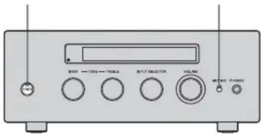
1 Press POWER to turn off the amplifier.
2 Hold down POWER while pressing MUTING to turn on the amplifier.
After "MEMORY CLEARING..."
appears on the display for a while,
"MEMORY CLEARED!" appears.
The following items are reset to their initial settings.
- All settings in the System Settings and Auto Calibration menus.
3 Release MUTING.
Additional Information
Precautions
On safety
Should any solid object or liquid fall into the cabinet, unplug the amplifier and have it checked by qualified personnel before operating it any further.
On power sources
- Before operating the amplifier, check that the operating voltage is identical with your local power supply.
The operating voltage is indicated on the nameplate on the back of the amplifier. - The unit is not disconnected from the AC power source (mains) as long as it is connected to the wall outlet, even if the unit itself has been turned off.
- If you are not going to use the amplifier for a long time, be sure to disconnect the amplifier from the wall outlet. To disconnect the AC power cord (mains lead), grasp the plug itself; never pull the cord.
- The AC power cord (mains lead) must be changed only at a qualified service shop.
On heat buildup
Although the amplifier heats up during operation, this is not a malfunction. If you continuously use this amplifier at a large volume, the cabinet temperature of the top, side and bottom rises considerably. To avoid burning yourself, do not touch the cabinet.
On placement
- Place the amplifier in a location with adequate ventilation to prevent heat buildup and prolong the life of the amplifier.
-
Do not place the amplifier near heat sources, or in a place subject to direct sunlight, excessive dust, or mechanical shock.
-
Do not place anything on top of the cabinet that might block the ventilation holes and cause malfunctions.
- Do not place the amplifier near equipment such as a television, VCR, or tape deck. (If the amplifier is being used in combination with a television, VCR, or tape deck, and is placed too close to that equipment, noise may result, and picture quality may suffer. This is especially likely when using an indoor antenna (aerial). Therefore, we recommend using an outdoor antenna (aerial).)
On operation
Before connecting other components, be sure to turn off and unplug the amplifier.
On cleaning
Clean the cabinet, panel, and controls with a soft cloth slightly moistened with a mild detergent solution. Do not use any type of abrasive pad, scouring powder, or solvent, such as alcohol or benzine.
If you have any questions or problems concerning your amplifier, please consult your nearest Sony dealer.
Troubleshooting
If you experience any of the following difficulties while using the amplifier, use this troubleshooting guide to help you remedy the problem. Should any problem persist, consult your nearest Sony dealer.
Audio
There is no sound, no matter which component is selected, or only a very low-level sound is heard.
- Check that the speakers and components are connected securely.
- Check that all speaker cords are connected correctly.
- Check that both the amplifier and all components are turned on.
- Check that VOLUME control is not set at -∞ dB.
- Press MUTING to cancel the muting function.
- Check that you have selected the correct component with INPUT SELECTOR.
- Check that headphones are not connected.
- The protective device on the amplifier has been activated. Turn off the amplifier, eliminate the short-circuit problem, and turn on the power again.
There is no sound from a specific component.
- Check that the component is connected correctly to the audio input jacks for that component.
- Check that the cord(s) used for the connection is (are) fully inserted into the jacks on both the amplifier and the component.
There is no sound from one of the speakers.
- Connect a pair of headphones to the PHONES jack to verify that sound is output from the headphones. If only one channel is output from the headphones, the
component may not be connected to the amplifier correctly. Check that all the cords are fully inserted into the jacks on both the amplifier and the component. If both channels are output from the headphones, the speaker may not be connected to the amplifier correctly. Check the connection of the speaker which is not outputting any sound.
- Make sure you have connected both the L or R jack to an analog component and not just to either the L or R jack. Use a monaural-stereo cable (not supplied).
The left and right sounds are unbalanced or reversed.
- Check that the speakers and components are connected correctly and securely.
- Adjust the balance parameters by pressing BALANCE on the remote.
There is severe hum or noise.
- Check that the speakers and components are connected securely.
- Check that the connecting cords are away from a transformer or motor, and at least 3 meters away from a TV set or fluorescent light.
- Move your TV away from the audio components.
- Make sure you have grounded the m SIGNAL GND terminal (only when a turntable is connected).
- The plugs and jacks are dirty. Wipe them with a cloth slightly moistened with alcohol.
Recording cannot be carried out.
- Check that the components are connected correctly (page 6, 7).
- Select the source component using INPUT SELECTOR (page 10, 12).
Remote control
The remote does not function.
- Point the remote at the remote sensor on the amplifier.
- Remove any obstacles in the path between the remote and the amplifier.
- Replace the lithium battery in the remote with a new one, if it is weak.
- Make sure you select the correct input on the remote.
- Set the remote command mode of the Sony CD player to CD1 (page 12).
Error messages
If there is a malfunction, the display shows a code of two numbers. You can check the condition of the system by the message. Refer to the following table to solve the problem. If any problem persists, consult your nearest Sony dealer.
CHECK CODE 11
Irregular current is output from the speakers. Turn off the amplifier, check the central core of a speaker cord is not touching the amplifier or other speakers, and turn on again.
CHECK CODE 12
The amplifier section is overheated. Check that the ventilation hole is not covered. Turn off the amplifier, leave the amplifier for a while, and turn on the power again.
CHECK CODE 14
Turn off the amplifier, check the central core of a speaker cord is not touching the amplifier or other speakers.
CHECK CODE 21
Turn off the amplifier and check that the speaker cords are connected correctly, then turn the power on again.
Specifications
Amplifier section
POWER OUTPUT
Rated Power Output
6 ohms 1 kHz, THD 0.7%:
65 W + 65 W
Power requirements 230 V AC, 50/60 Hz
Frequency response
| PHONO RIAA equalization curve ± 0.5 dB | |
| TUNER, SA-CD/CD, TAPE | 10 Hz - 40 kHz ± 3 dB (8 ohms) |
| Inputs (Analog) | |
| PHONO Sensitivity: 2.5 mV | |
| Impedance: 50 kohms S/N: 86 dB (A, 20 kHz LPF) | |
| TUNER, SA-CD/CD, TAPE | Sensitivity: 150 mV Impedance: 50 kohms S/N: 96 dB (A, 20 kHz LPF) |
| Output (Analog) | |
| TAPE Voltage: 150 mV | Impedance: 1 kohm |
| Inputs (Digital) | |
| DIGITAL 1/2/3 Impedance: 75 ohms S/N: 96 dB (A, 20 kHz LPF) | |
| DIGITAL 4 S/N: 96 dB | (A, 20 kHz LPF) |
| Output (Digital) | |
| DIGITAL 4 S/N: 96 dB | (A, 20 kHz LPF) |
| TONE | |
| TREBLE ±10 dB, 1 dB step | |
| BASS ±10 dB, 1 dB step | |
General
Power requirements 230 V AC, 50/60 Hz
Power consumption 60 W
Dimensions (w/h/d) (Approx.) 280 × 111 ×
286 mm
including projecting parts
and controls
Mass (Approx.) 4.6 kg
Supplied accessories
Operating Instructions (this manual)
Optimizer microphone ECM-AC1 (1)
AC power cord (mains lead) (1)
Remote commander RM-AAU012 (1)
Design and specifications are subject to change without notice.
Index
Symbols
SIGNAL GND terminal 6, 11
A
AC power cord 8
Auto Calibration 13
B
BALANCE 12
C
CD player 6,7
D
DAT deck 7
Display 10
DVD player/DVD recorder 7
E
Error messages 21
|
INPUT SELECTOR 10
L
LOUDNESS 12
M
MD deck 7
Menu
Auto Calibration 15
System Settings 17
MUTING 10, 12
0
Operation buttons for a Sony CD player 12
P
PHONES 10
R
Remote 12
Preparing 9
Resetting 18
S
Satellite tuner 7
Speakers 5
Super Audio CD player 6,7
T
Tape deck 6
TONE 10
V
VCR 6
VOLUME (VOL) 10, 12
AVERTISSEMENT
Précautions ......20
Dépannage ......21
Câble audio (non fourni)


Remarque
natural_image
Pure mechanical component diagram without any text, numbers, or symbolsnatural_image
Mechanical assembly diagram showing a pipe fitting with a circular component and directional arrows indicating motion (no text or symbols)1 Partie AUDIO INPUT/OUTPUT
- LOW-A, STD-A, HIGH-A, LOW-B, STD-B, HIGH-B
natural_image
Pure diagram of a double-line connector with two connectors and connecting links (no text or symbols)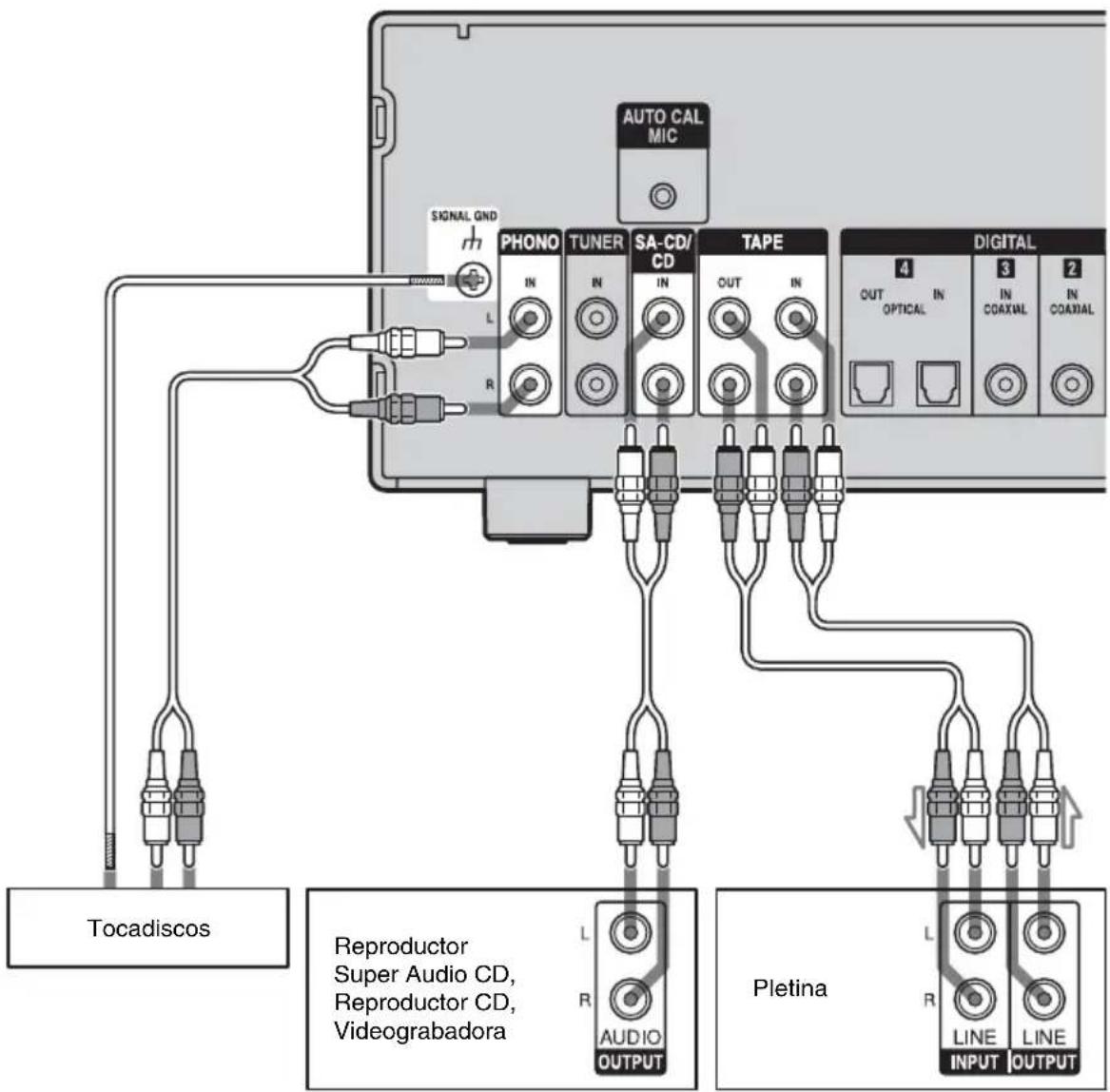
Nota
natural_image
Pure mechanical component diagram without any text, numbers, or symbolsnatural_image
Mechanical assembly diagram showing pipe connection and housing component (no text or symbols)- WARNING CODE [ :4■]
* TSP (Time Stretched Pulse)
(DC Phase Linearizer)
natural_image
Pure mechanical component diagram without any text, numbers, or symbolsnatural_image
Mechanical assembly diagram showing a pipe fitting and a housing component with a circular component (no text or symbols)- LOW-A, STD-A, HIGH-A, LOW-B, STD-B, HIGH-B
- Integrated Stereo Amplifier
- To reduce the risk of fire or electric shock, do not expose this apparatus to rain or moisture.
- CAUTION
- NOTICE FOR THE CUSTOMERS IN THE UNITED KINGDOM
- Disposal of Old Electrical & Electronic Equipment (Applicable in the European Union and other European countries with separate collection systems)
- About this manual
- Table of contents
- Getting Started
- Location of Parts and Operation
- Configuration
- Additional Information
- Unpacking
- Notes on connections
- Connecting speakers
- Notes on speaker connections
- Connecting components with analog audio input/output jacks
- Note
- Connecting components with digital audio input/output jacks
- Connecting to the COAXIAL jack Connecting to the OPTICAL jack
- Coaxial digital cord (not supplied)
- Optical digital cord (not supplied)
- Notes
- Tip
- Connecting the AC power cord (mains lead)
- Preparing the remote
- Pull out the insulating sheet to allow power to flow from the battery.
- Replacing the battery in the remote
- Notes on lithium battery
- WARNING
- Front panel
- Name Function
- Rear panel
- Remote commander
- Calibrating the appropriate speaker settings automatically (AUTO CALIBRATION)
- Before you perform auto calibration
- Performing the measurement
- To cancel the measurement
- Confirming/saving the measurement results
- When error codes appear
- •CODE 32, 33, 34
- When you select "WRN CHECK"
- Press to return to step 1 of "Confirming/saving the measurement results."
- Auto Calibration menu parameters
- ■ AUTO CAL START? (Starts auto calibration)
- CAL TYPE
- (Parameter type)
- ■ EQ CURVE EFFECT
- (Activates/deactivates the EQ curve measurement)
- Settings for the amplifier
- To exit the menu
- System Settings menu parameters
- ■ DEC. PRIORITY (Digital audio input decoding priority)
- ■ DUAL MONO (Bilingual audio selection)
- ■ D.RANGE COMP. (Dynamic range compressor)
- ■ DC PHASE L. (DC Phase Linearizer)
- Clearing the amplifier's memory
- Precautions
- On safety
- On power sources
- On heat buildup
- On placement
- On operation
- On cleaning
- Troubleshooting
- Audio
- There is no sound, no matter which component is selected, or only a very low-level sound is heard.
- There is no sound from a specific component.
- There is no sound from one of the speakers.
- The left and right sounds are unbalanced or reversed.
- There is severe hum or noise.
- Recording cannot be carried out.
- Remote control
- The remote does not function.
- Error messages
- CHECK CODE 11
- CHECK CODE 12
- CHECK CODE 14
- CHECK CODE 21
- Specifications
- Amplifier section
- General
- Supplied accessories
- Index
- Symbols
- A
- B
- C
- D
- E
- |
- L
- M
- 0
- P
- R
- S
- T
- V
- AVERTISSEMENT
- Remarque
- Nota
- (DC Phase Linearizer)
Brand : SONY
Model : TA-F501ES
Category : Receiver