
Row 8.1 - Rowing Machine TUNTURI - Free user manual and instructions
Find the device manual for free Row 8.1 TUNTURI in PDF.


| Product type | Rowing machine |
| Brand | Tunturi |
| Model | Row 8.1 |
| Resistance | Magnetic, 8 levels |
| Dimensions (L x W x H) | 215 x 55 x 60 cm |
| Weight | 34 kg |
| Maximum user weight | 150 kg |
| Power supply | Batteries (not included) or AC adapter (optional) |
| Display | LCD screen with time, distance, calories, strokes/min, watt |
| Main functions | Preset programs, heart rate measurement (handlebars), performance tracking |
| Maintenance and cleaning | Clean with a damp cloth, lubricate the rail every 3 months |
| Safety | Adjustable pedals with straps, emergency magnetic stop |
| Spare parts and repairability | Available via customer service, repairability rated 7/10 |
| Warranty | 2 years (parts and labor) |
| General information | Folds for vertical storage, transport wheels |
Frequently Asked Questions - Row 8.1 TUNTURI
User questions about Row 8.1 TUNTURI
0 question about this device. Answer the ones you know or ask your own.
Ask a new question about this device
Download the instructions for your Rowing Machine in PDF format for free! Find your manual Row 8.1 - TUNTURI and take your electronic device back in hand. On this page are published all the documents necessary for the use of your device. Row 8.1 by TUNTURI.
USER MANUAL Row 8.1 TUNTURI
natural_image
Technical line drawing of a mechanical exercise machine (no text or symbols present)It's easy to feel good!
Contents
Introduction......4
Safety warnings......4
Workouts......5
Heart rate measurement 5
Maximum heart rate.... 6
Assembly.... 6
Parts out of box 6
Box content list....6
General assembly information......7
Assembly steps 7
Setting the rowing resistance ..... 10
Getting started....11
Adjust tank water level....11
Filling the tank with water....11
Removing water from the tank.... 12
Water treatment....12
Slider footplate 12
Adjusting the footplate....12
How to row 13
How often 13
Rowing console....13
Detaching the rowing belt....15
Re-attaching the rowing belt ..... 15
Troubleshooting 16
Warranty 17
Declaration of the manufacturer ..... 17
Disclaimer 17
Specifications product......62
Spare parts....62
Exploded view 64
Introduction
Welcome to the world of Tunturi New Fitness!
Thank you for purchasing this piece of Tunturi equipment. Tunturi offers a wide range of professional fitness equipment, including crosstrainers, treadmills, exercise bikes, rowers and vibration plates. The Tunturi equipment is suitable for the entire family, no matter what fitness level. For more information, please visit our website www.tunturi.com
Safety warnings

WARNING
Read the safety warnings and the instructions. Failure to follow the safety warnings and the instructions can cause personal injury or damage to the equipment. Keep the safety warnings and the instructions for future reference.

WARNING
Heart rate monitoring systems may be inaccurate. Over exercise may result in serious injury or death. If you feel faint stop exercising immediately.
- The equipment is suitable for domestic and professional use only (e.g. hospitals, fire stations, hotels, schools etc.). Max. usage is limited to 6 hrs a day. The equipment is not suitable for full commercial use (e.g. large gyms).
- The use of this equipment by children or persons with a physical, sensory, mental or motorial disability, or lack of experience and knowledge can give cause to hazards. Persons responsible for their safety must give explicit instructions or supervise the use of the equipment.
- Before starting your workout, consult a physician to check your health.
- If you experience nausea, dizziness or other abnormal symptoms, immediately stop your workout and
consult a physician.
- To avoid muscular pain and strain, start each workout by warming up and finish each workout by cooling down. Remember to stretch at the end of the workout.
- The equipment is suitable for indoor use only. The equipment is not suitable for outdoor use.
- Only use the equipment in environments with adequate ventilation. Do not use the equipment in draughty environments in order not to catch a cold.
- Only use the equipment in environments with ambient temperatures between 10 °C and 35 °C. Only store the equipment in environments with ambient temperatures between 5 °C and 45 °C.
- Do not use or store the equipment in humid surroundings. The air humidity must never be more than 80%.
- Only use the equipment for its intended purpose. Do not use the equipment for other purposes than described in the manual.
- Do not use the equipment if any part is damaged or defective. If a part is damaged or defective, contact your dealer.
- Keep your hands, feet and other body parts away from the moving parts.
- Keep your hair away from the moving parts.
- Wear appropriate clothing and shoes.
- Keep clothing, jewellery and other objects away from the moving parts.
- Make sure that only one person uses the equipment at a time. The equipment must not be used by persons weighing more than 150kg (330lbs).
- Do not open equipment without consulting your dealer.
- Follow instructions provided in this manual for correct foot position and basic rowing techniques.

WARNING
- The equipment can stand vertically for storage. Make sure a secure location is chosen, such as in the corner of a room.
- Place the equipment on a firm, level surface.
- Place the equipment on a protective base to prevent damage to the floor surface.
- Allow at least 100 cm of clearance around the equipment.
Workouts
The workout must be suitably light, but of long duration. Aerobic exercise is based on improving the body's maximum oxygen uptake, which in turn improves endurance and fitness. You should perspire, but you should not get out of breath during the workout.
To reach and maintain a basic fitness level, exercise at least three times a week, 30 minutes at a time. Increase the number of exercise sessions to improve your fitness level.
It is worthwhile to combine regular exercise with a healthy diet. A person committed to dieting should exercise daily, at first 30 minutes or less at a time, gradually increasing the daily workout time to one hour. Start your workout at low speed and low resistance to prevent the cardiovascular system from being subjected to excessive strain.
As the fitness level improves, speed and resistance can be increased gradually. The efficiency of your exercise can be measured by monitoring your heart rate and your pulse rate.
Heart rate measurement
(HEART RATE CHEST BELT)

NOTE
The product does not come standard with a build in heart rate receiver. To prepare the equipment for a heart rate chest belt you need to install the additional Heart rate receiver, available as a kit. Contact your local distributor for details.
The most accurate heart rate measurement is achieved with a heart rate chest belt. The heart rate is measured by a heart rate receiver in combination with a heart rate transmitter belt. Accurate heart measurement requires that the electrodes on the transmitter belt are slight moist and constantly touching the skin. If the electrodes are too dry or too moist, the heart rate measurement might become less accurate.

WARNING
- If you have a pacemaker, consult a physician before using a heart rate chest belt.

CAUTION
- If there are several heart rate measurement devices next to each other, make sure that the distance between them is at least 2 meter.
- If there is only one heart rate receiver and several heart rate transmitters, make sure that only one person with a transmitter is within transmission range.

NOTE
- Always wear the heart rate chest belt under your clothes directly in contact with your skin. Do not wear the heart rate chest belt above your clothes. If you wear the heart rate chest belt above your clothes, there will be no signal.
- If you set a heart rate limit for your workout, an alarm will sound when it is exceeded.
- The transmitter transmits the heart rate to the console up to a distance of 1.5 meter. If the electrodes are not moist, the heart rate will not appear on the display.
- Some fibers in clothes (e.g. polyester, polyamide) create static electricity which can prevent accurate heart rate measurement.
- Mobile phones, televisions and other electrical appliances create an electromagnetic field which can prevent accurate heart rate measurement.
Maximum heart rate
(DURING TRAINING)
The maximum heart rate is the highest heart rate a person can safely achieve through exercise stress. The following formula is used to calculate the average maximum heart rate: 220 - AGE. The maximum heart rate varies from person to person.

WARNING
Make sure that you do not exceed your maximum heart rate during your workout. If you belong to a risk group, consult a physician.
Beginner: (50-60% of max. heart rate)
Suitable for beginners, weight-watchers, convalescents and persons who have not exercised for a long time. Exercise at least three times a week, 30 minutes at a time.
Advance: (60-70% or max. heart rate)
Suitable for persons who want to improve and maintain fitness. Exercise at least three times a week, 30 minutes at a time.
Expert: (70-80% or max. heart rate)
Suitable for the fittest of persons who are used to long-endurance workouts.
Assembly
Parts out of box

Box content list
| Item Description |
| 1 Main frame |
| 2 Seat rail (boxed separately) |
| 3 Rower seat |
| 4 Horizontal seat rail bolt(M10x120mm) |
| 5 Washer (M10) |
| 6 Nylock nut (M10) |
| 7 Vertical seat rail tensioning bolt(M10x150mm) |
| 8 Plastic dome cap |
| 9 Rear seat rail bumpstop |
| 10 Seat rail end cap |
| 11 Rear leg |
| 12 Seat rail bracket |
| 13 Rear leg bolts - dome(M10x120mm) |
| 14 AA Batteries (x2) |
| 15 Multi tool |
| 16 Hex key (8mm) |
| 17 Hex key (6mm) |
| 18 Owners manual |
| 19 Siphon |
| 20 Water treatment tablets (x4) |
| 21 Vertical seat rail bolt dampener |
| 22 Internal seat rail bolt bracket |
The package contains the parts as shown in figure.
If a part is missing, contact your dealer.
General assembly information
WARNING
- Assemble the equipment in the given order.
- Carry and move the equipment with at least two persons.
CAUTION
- Place the equipment on a firm, level surface.
- Place the equipment on a protective base to prevent damage to the floor surface.
- Allow at least 100 cm of clearance around the equipment.

Refer to the illustrations for the correct assembly of the equipment.
Assembly steps
ASSEMBLY STEP 1

• Install the rower seat (3) onto the seat rail (2) as shown.

NOTE
- The rail rear end has two mounting holes.
ASSEMBLY STEP 2
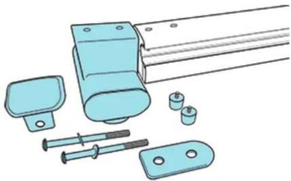
natural_image
Illustration of various mechanical components including a shaft, bracket, screwdriver, and nut (no text or symbols)For the next assembly step, you will need:
- rear leg (11)
- 2x rear seat rail bumpstops (9)
- 2x rear leg bolts (M10x120mm) (13)
- 2x washer (5)
- seat rail bracket (12)
- rubber end cap (10)
• -internal seat rail bracket (22)
ASSEMBLY STEP 3

natural_image
Illustration of hands installing or adjusting a mechanical component with a tool (no text or symbols visible)With the seat already installed on the rail, thread the rear rubber bumpstops (9) onto the end of the seat rail (2) as shown.
ASSEMBLY STEP 4

- Insert the internal seat rail back (22) into the rear end of the rail and align the internal seat rail bracket hole with the seat rail front bolt hole.
- Insert the bolt (13) with washer (5) through the seat rail bracket (12) into the seat rail front bolt hole and internal seat rail bracket.
- Secure the bolt into the rear leg (11)

NOTE
- The oval end of the seat rail bracket (12) is facing forward as shown.
- Do not thighten the bolt (13).
ASSEMBLY STEP 5
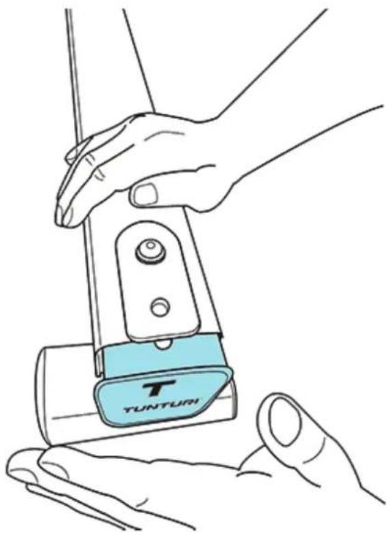
natural_image
Line drawing of hands operating a Tunturi device (no text or symbols on the device itself)Install the rubber end cap (10)
ASSEMBLY STEP 6

natural_image
Line drawing of hands using a tool to adjust or install a mechanical component (no text or symbols present)- Finish the rear leg assembly by installing the second rear leg bolt (13) and washer (5).
- Tighten both front and rear bolts.
Be careful tightening bolts to prevent scratches
ASSEMBLY STEP 6

natural_image
Line drawing of hands using a tool to adjust or install a mechanical component (no text or symbols present)- Finish the rear leg assembly by installing the second rear leg bolt (13) and washer (5).
- Tighten both front and rear bolts.
Be careful tightening bolts to prevent scratches
ASSEMBLY STEP 7
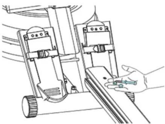
natural_image
Line drawing of a robotic arm with a hand holding a tool, no text or symbols presentFor the next assembly step, you will need:
- seat rail assembly (previously assembled)
- main frame (1)
- 2x horizontal seat rail bolts (M10x120mm) (4)
- 2x washer (5)
- 2x nylock nuts (6)
ASSEMBLY STEP 8

natural_image
Technical line drawing of a mechanical assembly with no visible text or symbolsInsert the seat rail until it just slightly protrudes behind the footplate. Shown above is the installation / alignment point for the M10x120mm horizontal seat rail bolt (4), M10 washer (5) and nylock nut (6)
ASSEMBLY STEP 9

natural_image
Illustration of a hand using a tool to adjust or install a mechanical component (no text or symbols visible)Install and secure the two bolts (4) and two washers (5) with the nylock nuts (6).
ASSEMBLY STEP 10

natural_image
Line drawing of a hand using a tool to adjust or install electronic components on a mechanical device (no text or symbols visible)• Install the vertical seat rail bolt (7) with plastic dome cap (8) through the seat rail assy.
- Fit the vertical seat rail bolt dampener (21) onto the bolt end sticking out of the seat rail assy.

NOTE
The vertical seat rail dampener is designed to take up the slack between the seat rail and mainframe when the rower is stored / standing in a vertical position.
ASSEMBLY STEP 11

natural_image
Technical line drawing of a mechanical device with hands operating it (no text or symbols present)- Secure the seat rail bolt with seat rail bolt dampener into the lower main frame (1).
Do not tighten the bolt (7).
The vertical seat rail tensioning bolt (7) is designed to hold the mid leg 3-5mm off the ground when the rower is standing on the ground without a person on it. During operation the mid leg will just slightly touch the ground during a rowing stroke.

NOTE
If excessive shaking/hopping of the tank occurs during rowing, this indicates the vertical seat rail tensioning bolt (7) is out of adjustment and should be tightened.
Setting the rowing resistance
(ADJUSTABLE WATER LEVEL)
The patented adjustable water level offers a true multi-level experience. Water is moved between the “storage” and “active” chambers of the tank. Your new Tunturi Rower can adapt - at the turn of a dial - to the resistance preferred by each user.

MAX:
This setting allows the maximum amount of water to reach the rowing Blades inside the tank for heaviest resistance
MIN:
Keeps a portion of the water in the inner tank compartment, creating light resistance.
Getting started
To achieve minimum resistance, select MIN on the tank adjuster. It takes 10 strokes to fill the central (storage) tank, leaving a minimal amount of water in the outer (active) tank. This process is always required if minimum resistance is desired.
Row hard at a steady pace (20 to 25 Strokes Per Minute [SPM]) and put some effort into the stroke, ensuring that good form is maintained.
You can make adjustments to the resistance level while you row. Your Tunturi rower will adapt almost instantly to increases in resistance but will take up to 10 strokes to reduce the effort required, as the inner storage tank fills up.
Once you have found a level that gives you the exercise required, changes can be made to the SPM and stroke intensity to further vary your energy input.
Interval training is used by most rowers, where a period of low intensity is combined with short intervals of high intensity. Your Tunturi rower allows instant changes, achieving multi-level resistance profiles during a single workout.
Adjust tank water level
Filling the tank with water
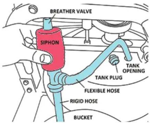
- Set the resistance adjuster handle to MAX
- Remove the rubber tank plug from the top of the tank.
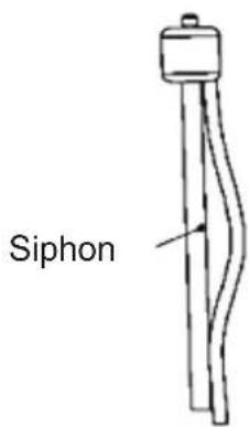
- Place a large bucket of water next to the rower and position the siphon with the rigid hose in the bucket and the flexible hose into the tank as shown. Make sure the small breather valve on the top of the siphon is closed before filling.

NOTE
• 17 liters of water is required for maximum filling.
- Where water quality is poor, we recommend using distilled water.
- Putting the bucket higher than the tank will allow the siphon to "self-pump" when adding water to the tank.
- Consider using a towel under the bucket and water tank preventing stains on the floor.

WARNING
Failure to set the adjuster handle to MAX prior to filling the tank will cause inaccurate fill levels and possible leakage.
- Begin filling the tank by squeezing the siphon. Use the level gauge decal on the side of the tank to measure volume of water in the tank.
• After filling the tank to the desired water level, open the valve on the top of the siphon to allow excess water to escape. - Ensure that the tank plug is replaced once filling and water treatment procedures are complete.
removing water from the tank
- Set the resistance adjuster handle to MIN.
- Row at least ten strokes to fill the inner storage reservoir as much as possible with water.
- Remove the tank plug.
- Insert the siphon rigid hose end into the tank
- Insert the siphon flexible hose end into a large bucket.
- Drain the tank (approx. 40% of water will remain in the tank. It is not possible to drain the tank completely without disassembling the tank)
- Refill the tank following the directions as described under the section "Filling the tank" of this manual.


NOTE
- The valve on top of the siphon must be closed to allow proper drainage.
- If the water treatment schedule is maintained, it will not be necessary to change the water inside the tank. An additional water treatment tablet is only required when discoloration of the water appears.
- Exposure to sunlight affects the water. Moving the rower away from direct sunlight will extend time between water treatments
Water treatment
- Add one water treatment tablet (20)
- Add a water treatment tablet whenever the water appears dirty or cloudy over time.

WARNING
- Only use the Tunturi supplied water treatment tablets.
Slider footplate
The slider footplate is designed to fit a wide range of foot sizes.
Adjusting the footplate
Lift the top of the sliding portion of the footplate and slide up or down. The numbers 1-6 represent a guideline from which the proper length can be determined. Secure the plate onto the mounting pegs and push down firmly to lock into position.
Tighten the foot straps securely and begin your workout.


WARNING
Never operate this rower without feet properly secured in Foot straps, or without the sliding portion of the Slider Footplate locked into position!
How to row
 | CatchComfortably forward with straight back and arms. |
 | DrivePush with the legs while arms remain straight. |
 | FinishPull through with arms and legs rocking slightly back on your pelvis. |
 | RecoveryUpper body tips forward over your pelvis and move forward. |
 | CatchBack to the starting positon and begin again. |
Catch - Drive
Begin the stroke comfortably in forward position and push strongly back with your legs while keeping your arms and back straight.
Finish
Begin to pull your arms back as they pass over your knees and continue the stroke through to completion rocking slightly back over your pelvis.
Recovery - Catch
Return to the starting position and repeat.
How often
Begin with 5 minute training sessions once a day and aim for a time around 2:30 to 2:45 for 500m distance. Row at a pace that keeps the water circulating continuously between strokes.
Progress a few minutes more each day until you are comfortable with 30-45 minutes training time 3 or 4 times a week.
This will provide aerobic endurance benefits, muscle toning and sufficient calorie burning to form part of a weight loss program.

WARNING
• Always consult a doctor before beginning an exercise program.
- Stop immediately if you feel faint or dizzy.
Rowing console
Auto Start:
Commence rowing to activate.
Reset all values:
Hold DISTANCE button down for 3 second to RESET.
Distance:
Add 1000m distance each button push to accumulate required distance then begin rowing to initiate count-back.
Auto-Pause:
A temporary halt in exercise will result in the following:
For over 5 seconds and under 5 minutes:
- SPM / 500M TIME / WATT return to zero.
- DISTANCE and TIME are put on hold, values are saved.
• CAL HOUR defaults to total calories used in this session.
A Resumption in exercise in less than 5 minutes will resume
DISTANCE and TIME from saved values automatically.
Auto Power Down:
After 5 minutes the console will shut down.
All values revert to zero after restart.
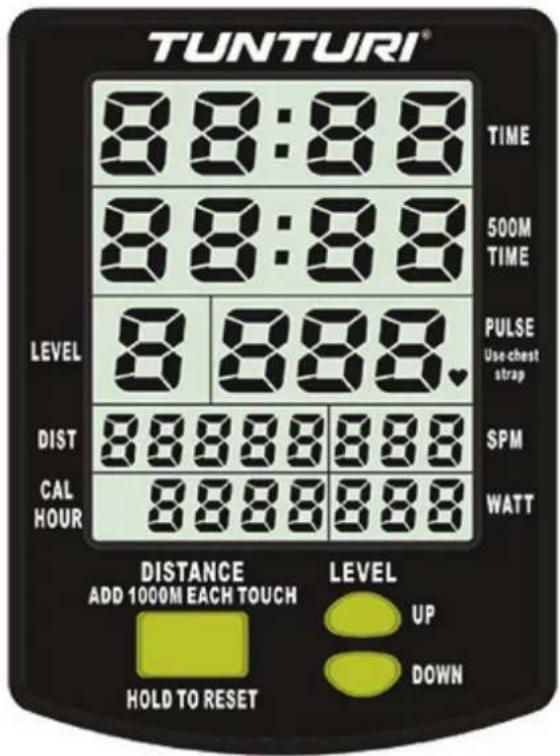
TIME Window:
Auto start elapsed time.
500M TIME Window:
Time to row 500m, updated at the completion of each stroke
PULSE Window:
Heart Rate pulse. Requires chast strap and receiver kit (sold separately)
SPM Window:
Stroke Per Minute, updated each stroke.
CAL HOUR Window:
Calories per hour, updated each stroke.
WATT Window:
Unit of power (W), updated each stroke.

Level up/ down


Use the yellow LEVEL UP / DOWN buttons on the console in conjunction with the tank resistance adjuster handle for accurate 500M TIME / DISTANCE / CAL HOUR / WATT.
Detaching the rowing belt

Untie the bungee cord or cut the plastic tiewrap holding the bungee at the bungee attachment point. The bungee attachment point is located at the bottom of the main frame.

natural_image
Line drawing of a mechanical device with hands operating it (no text or symbols)Pull the bungee cord through all three pulleys and leave excess on top of the tank for now.

To detach belt, simply pull beyond the range of the normal rowing stroke until the belt detaches from the belt bungee pulley.

NOTE
You will hear the velcro separating just before the belt detaches.
Re-attaching the rowing belt

natural_image
Illustration of a car interior showing hand positioning and blue ribbon cable (no text or symbols)- Begin re-attaching by guiding the rower belt around the rower belt pulley.
- The velcro side should be facing upward as illustrated.

- Next, guide the belt around the idle wheel as shown.
- Once around the idle wheel, attach the rower belt to the belt / bungee pulley. There is an obvious "lip" at the attachment point.

- Wind the rower belt onto the belt / bungee pulley until the rower handle is at its furthest forward position.

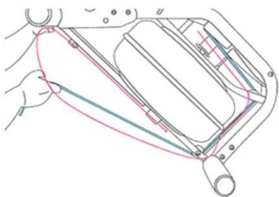
- 6. Re thread the bungee cord (on opposite side of the idle wheel) back through the bungee pulleys and tie off at the attachment point.
BUNGEE CORD ROUTE (RED LINE)
natural_image
Technical line drawing of a mechanical assembly with hands operating a component (no text or symbols)
NOTE
- If bungee cord previous tension seemed correct (a good way to judge is if the rower handle can make it to the furthest point forward on the top of the mainframe under bungee tension alone) then simply tie off at previous position.
- If the return is too slack, experiment by tightening the tension in small increments and testing until the correct tension is achieved.
- If the rower handle cannot reach the end of the seat rail during a rowing stroke, then the bungee cord is over-tensioned.
Troubleshooting
Water changes color or becomes cloudy
Possible cause:
Rower is in direct sunlight or has not had water treatment.
Solution:
- Change rower location to reduce direct exposure to sunlight.
- Add water treatment or change tank water as directed in the water treatment section of this manual.
Rower belt slipping off belt / bungee pulley
Possible cause:
Bungee cord not under enough tension.
Solution:
- Tighten bungee cord following the instructions in "Re-attaching the rowing belt" - step 8 of this manual.
Front of rower lifts slightly during vigorous rowing.
Possible cause:
Vertical seat rail tensioning bolt (M10x150mm) is too loose.
Solution:
- Tighten bolt 1/2 turn and row again. Tighten as needed until problem stops.
Over tightening this bolt can damage the seat rail. Only tighten bolt in small increments until fault is corrected.
The rowing console does not illuminate after battery installation.
Possible cause:
Batteries installed incorrectly or need replacing.
Solution:
- Reinstall batteries in correct position and try again.
- If the LCD screen fails to illuminate, try rotating the batteries slightly in the console.
- If this fails, contact your local service centre.
The rowing console screen illuminates, but does not register when rowing.
Possible cause:
Loose or failed connection
Solution:
- Check that the console lead is connected properly.
- If it is connected then contact your local service centre.
Warranty
The product has a warranty from the date of delivery (to be documented by invoice or delivery note). Further information on warranty terms can be obtained from your local dealer. The warranty terms may vary from one country to another. Damages caused by normal wear, overloading or improper handling are excluded from the warranty. Damages caused by material or manufacturing faults are covered by the warranty and will repaired or replaced at no cost.
Declaration of the manufacturer
Tunturi New Fitness BV declares that the product is in conformity with the following standards and directives: EN 957 (SC), 89/336/EEC. The product therefore carries the CE label.
09-2014
Tunturi New Fitness BV
P.O. Box 60001
1320 AA Almere
The Netherlands
Disclaimer
© 2014 Tunturi New Fitness BV All rights reserved.
The product and the manual are subject to change.
Specifications can be changed without further notice.
DEUTSCH
Specifications product......62
Spare parts....62
Exploded view 64
Einführung
| 14 AA Batteries (x2) |
| 15 Multi tool |
| 16 Hex key (8mm) |
| 17 Hex key (6mm) |
| 18 Owners manual |
| 19 Siphon |
| 20 Water treatment tablets (x4) |
| 21 Vertical seat rail bolt dampener |
| 22 Internal seat rail bolt bracket |
natural_image
Illustration of various mechanical components including a shaft, bracket, and screws (no text or symbols)- rear leg (11)
• ·2x rear seat rail bump stops (9)) - 2x rear leg bolts (M10x120mm) (13)
- 2x washer (5)
- seat rail bracket (12)
- rubber end cap (10)
• ·internal seat rail bracket (22)
MONTAGESCHRITT 3

natural_image
Illustration of hands assembling a mechanical component with a tool (no text or symbols visible)natural_image
Line drawing of hands operating a Tunturi device (no text or symbols present)Installere den rubber end cap (10).
MONTAGESCHRITT 6

natural_image
Line drawing of hands using a tool to adjust or install a mechanical component (no text or symbols present)natural_image
Line drawing of a robotic arm with a hand holding a tool, no text or symbols presentnatural_image
Technical line drawing of a mechanical assembly with no visible text or symbolsnatural_image
Illustration of a hand using a tool to adjust or install a mechanical component (no text or symbols visible)natural_image
Line drawing of a hand using a wrench to adjust or install a mechanical component (no text or symbols present)natural_image
Technical line drawing of a mechanical device with hands operating it (no text or symbols present)MAX:
natural_image
Line drawing of a hand operating a mechanical device with no visible text or symbolsnatural_image
Illustration of a hand adjusting a blue ribbon cable (no text or symbols)natural_image
Technical line drawing of a mechanical device with no visible text or symbols
HINWEIS
Front of rower lifts slightly during vigorous rowing.
Mögliche Ursache:
Tunturi New Fitness BV
P.O. Box 60001
1320 AA Almere
The Netherlands
Haftungsausschluss
© 2014 Tunturi New Fitness BV
All rights reserved.
LISTE DES PIECES FOURNIES
natural_image
Illustration of various mechanical components including a shaft, bracket, and screws (no text or symbols)natural_image
Illustration of hands installing or adjusting a mechanical component with a tool (no text or symbols visible)natural_image
Line drawing of hands operating a TUNTURI electric shaver device (no text or symbols on the device itself)natural_image
Illustration of hands using a tool to adjust or install a mechanical component (no text or symbols visible)natural_image
Technical line drawing of a mechanical device with a hand holding a tool, no visible text or symbolsnatural_image
Technical line drawing of a mechanical assembly with no visible text or symbolsnatural_image
Illustration of a hand using a tool to adjust or install a mechanical component (no text or symbols visible)natural_image
Line drawing of a hand using a tool to adjust or install electronic components on a mechanical device (no text or symbols visible)natural_image
Technical line drawing of a mechanical device with hands operating it (no text or symbols present)natural_image
Line drawing of a mechanical assembly with hands operating a tool (no text or symbols)natural_image
Illustration of a hand adjusting a blue ribbon cable (no text or symbols)natural_image
Technical line drawing of a mechanical device with no visible text or symbolsPARCOURS DU CABLE ELASTIQUE (LIGNE ROUGE)

REMARQUE
Tunturi New Fitness BV
P.O. Box 60001
1320 AA Almere
The Netherlands
© 2014 Tunturi New Fitness BV.
Inhoud van de doos
natural_image
Illustration of various mechanical components including a shaft, bracket, screwdriver, and bolts (no text or symbols)natural_image
Illustration of hands installing or adjusting a mechanical component with a tool (no text or symbols visible)natural_image
Line drawing of hands operating a TUNTURI handheld device (no text or symbols on the device itself)natural_image
Illustration of hands using a tool to adjust or install a mechanical component (no text or symbols visible)natural_image
Line drawing of a robotic arm with a hand holding a tool, no text or symbols presentnatural_image
Technical line drawing of a mechanical assembly with no visible text or symbolsnatural_image
Illustration of a hand using a tool to adjust or install a mechanical component (no text or symbols visible)natural_image
Line drawing of a robotic device with a hand using a wrench to adjust the component (no text or symbols present)natural_image
Technical line drawing of a mechanical tool with hands operating it, no visible text or symbols
OPMERKING
natural_image
Line drawing of a mechanical device with hands operating it (no text or symbols)natural_image
Illustration of a hand adjusting a blue ribbon cable (no text or symbols)natural_image
Technical line drawing of a mechanical assembly with no visible text or symbols
OPMERKING
Tunturi New Fitness BV
Postbus 60001
1320 AA Almere
Nederland
Disclaimer
© 2014 Tunturi New Fitness BV.
Adjustable water resistance, tank volume up to 17 ltr (4,5 gal)
PRODUCT
Folding ......NO (standing straigth up)
Power supply ...... Battery (4xAA type)
Heigth 52 cm
Length 217 cm
Width 51 cm
Weigth 26,2 kg
Max. userweigth .....135 kg /300 lbs
MONITOR
Display...... LCD Monochrome
Programs......Manual + 500 m time
Ergometer..... Yes
Control......Buttons
QUALITY
EN-957 CLASS ....SA

NOTE
The Pure Rower 8.1 does not come with a standard build in heart rate receiver.
A heart rate receiver kit is available and can be purchased separately.
Tunturi New Fitness item number for the Heart rate receiver kit is: 14TRW08011
- This kit does not come with the chest strap
- The heart rate receiver kit is a 5,4 Khz receiver type of module.
Spare parts
| # | Description Qty | |
| 1 | Counter sunk tapping screw (M3x20 sus) | 12 |
| 2 | Nylock nut (M10) 1 | |
| 3 | Seat 1 | |
| 4 | Washer (M6x16x1) 2 | |
| 5 | Washer (M10x21x2) 4 | |
| 6 | Nylock nut (M6) 2 | |
| 7 | Foot strap & buckle 2 | |
| 8 | Handle grip 2 | |
| 9 | Handlebar O-ring 2 | |
| 10 | Handle bar & belt | 1 |
| 11 | End cap rear rail support (50x100) | 2 |
| 12 | Bolt (M8x60) | 3 |
| 13 | Decal (how to row) | 1 |
| 14 | Handlebar rubber cover | 1 |
| 15 | Foot levelers (M8x30) hardened rubber | 2 |
| 16 | Nylock nut (M5 -b) | 8 |
| 17 | Bungee pulley spacer (8mm) | 4 |
| 18 | Bungee pulley (50mm) | 1 |
| 19 | Belt pulley spacer (10mm) | 2 |
| 20 | Belt pulley 100mm & 2x bearing | 1 |
| 21 | Main shaft oil bushing - lower | 1 |
| 22 | Sensor disk (& 6x24) | 1 |
| 23 | Roll pin (6mm) | 2 |
| 24 | Magnet (5x4) | 6 |
| 25 | Dome head bolt (M8x65) | 1 |
| 26 | Round head phillips screw (M3x20 sus) | 24 |
| 27 | Nylock nut (M3 sus) | 24 |
| 28 | Impeller end cap | 1 |
| 29 | Tank internal screw (M6x15 sus) | 3 |
| 30 | Computer mount plastic bushing | 2 |
| 31 | Speed sensor (300mm) | 1 |
| 32 | Frame plug (∅ 38.1) | 1 |
| 33 | O ring 9.5x6.5x1.5 | 2 |
| 34 | Main shaft nylon bushing - upper | 1 |
| 35 | Round end cap (∅ 76.2 ) | 4 |
| 36 | Transport wheel fastener | 4 |
| 37 | Transport wheel 76.2 | 2 |
| 38 | Lower frame end cap (25x50) | 2 |
| 39 Plastic spacer (15*6*2.5t) 2 | |
| 40 Bungee cord (8mmx1950) 1 | |
| 41 Washer (M8.5x19x1.6t) 1 | |
| 42 Nylock nut (M8) 1 | |
| 43 Plastic dome cap (10mm) 1 | |
| 44 Belt/bungee compl. & bearings, velcro | 1 |
| 45 Tank bonding strip 3m-vhb 4 | |
| 46 Dome head bolt (M5x15) 8 | |
| 47 Internal seat rail supp. bracket 1 | |
| 48 Curved washer (M10 ) 4 | |
| 49 Dome head bolt for seat rail (M10x120) | 2 |
| 50 Hex head bolt (M10x120) 1 | |
| 51 Dome head bolt (M10x150) 1 | |
| 52 Vertical seat rail bolt dampener 1 | |
| 53 Tank plug for hs tank 1 | |
| 54 Hex head bolt (M10x120) 4 | |
| 55 Idle wheel compl. with bearing & shaft | 1 |
| 56 Rubber end cap - main frame 1 | |
| 57 Seat wheel 6 | |
| 58 Dome head bolt (M8x70 -b) 1 | |
| 59 Dome head bolt (M10x60 -b) 1 | |
| 60 Washer (8.5x19x1.6t - b) 12 | |
| 61 Grub screw (M4x6 - b) 1 | |
| 62 Nylock nut (M8 -b) 11 | |
| 63 Decal (Tank water level) 1 | |
| 64 Seat wheel short spacer (12.7x8.1x13 - b) | 6 |
| 65 Plastic spacer for ar tank 1 | |
| 66 Impeller 1 | |
| 67 Lower outer tank shell 1 | |
| 68 Upper outer tank shell 1 | |
| 69 Inner reserve tank shell 1 | |
| 70 Decal (Resistance knob) 1 | |
| 71 Pulley 50mm with bearing & spacer | 2 |
| 72 Grub screw (M3x12 sus) 4 | |
| 73 Velcro for sliding footplate 2 | |
| 74 Footrest plate slider 2 | |
| 75 Footrest plate slider base 2 | |
| 76 Tank upper/ lower shell seal 1 |
| 77 User interface | 1 | |
| 78 Upper main frame | 1 | |
| 79 Lower main frame | 1 | |
| 80 Rear rail support | 1 | |
| 81 Seat rail rail end cap | 1 | |
| 82 Seat rail profile | 1 | |
| 83 Decal (How to adjust resistance) | 1 | |
| 84 Tank adjuster outer cup | 1 | |
| 85 Tank adjuster inner cup | 1 | |
| 86 Adjuster knob | 1 | |
| 87 End cap-adjuster knob | 1 | |
| 88 Rail support assembly bracket | 1 | |
| 89 Rubber bumper | 1 | |
| 90 Spacer for seat | 2 | |
| 91 Seat frame bracket | 2 | |
| 92 Hex head bolt (M8x45) | 2 | |
| 93 Rubber hook cover | 2 | |
| 94 Bearing for bungee pulley | 2 | |
| 95 Velcro for bungee pulley | 1 | |
| 96 Belt bungee pulley complete kit | 1 | |
| Complete pre assembled parts | ||
| Seat rail set (&82) | ||
| Seat frame and wheel assembly | ||
| Handlebar complete (& 8,9,10,14) | ||
| Tank assembly complete | ||
| Extra parts not shown in drawing | ||
| Siphon | ||
| Hardware kit | ||
| Water treatment tablets - 4 tabs | ||
| Owners manual | ||
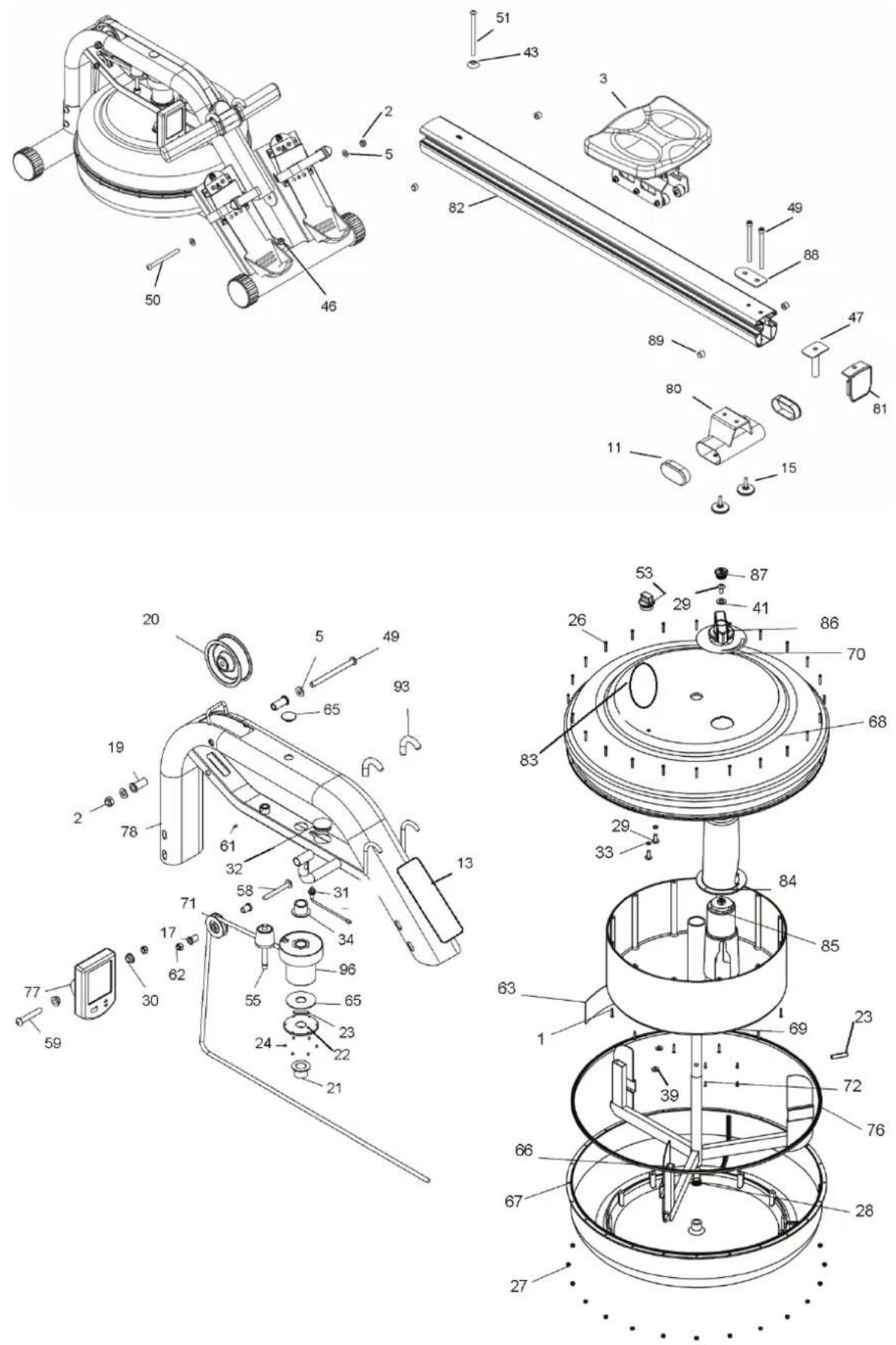
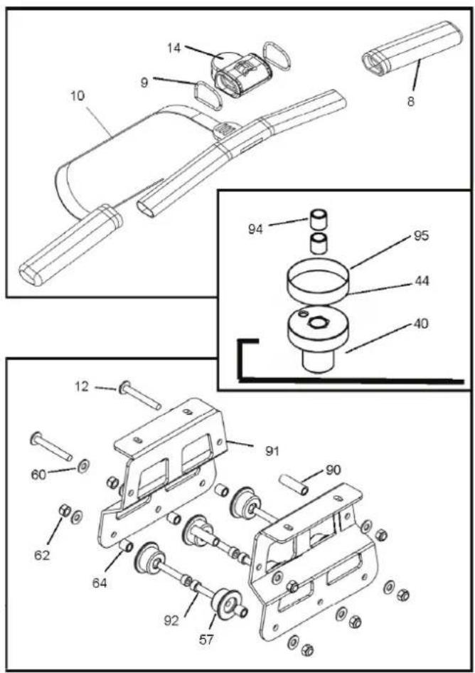
Exploded view
Owner's manual • PURE ROW 8.1

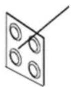
water treatment tablets
TUNTURI®
Tunturi New Fitness B.V.
P.O. Box 60001
1320 AA
The Netherlands
www.tunturi.com
20141216

- Contents
- Introduction
- Safety warnings
- WARNING
- Workouts
- Heart rate measurement
- (HEART RATE CHEST BELT)
- NOTE
- CAUTION
- Maximum heart rate
- (DURING TRAINING)
- Beginner: (50-60% of max. heart rate)
- Advance: (60-70% or max. heart rate)
- Expert: (70-80% or max. heart rate)
- Assembly
- General assembly information
- Assembly steps
- Setting the rowing resistance
- (ADJUSTABLE WATER LEVEL)
- MAX:
- MIN:
- Getting started
- Adjust tank water level
- removing water from the tank
- Water treatment
- Slider footplate
- Adjusting the footplate
- How to row
- Catch - Drive
- Finish
- Recovery - Catch
- How often
- Rowing console
- Auto Start:
- Reset all values:
- Distance:
- Auto-Pause:
- Auto Power Down:
- TIME Window:
- 500M TIME Window:
- PULSE Window:
- SPM Window:
- CAL HOUR Window:
- WATT Window:
- Detaching the rowing belt
- Re-attaching the rowing belt
- Troubleshooting
- Water changes color or becomes cloudy
- Solution:
- Rower belt slipping off belt / bungee pulley
- Front of rower lifts slightly during vigorous rowing.
- The rowing console does not illuminate after battery installation.
- The rowing console screen illuminates, but does not register when rowing.
- Warranty
- Declaration of the manufacturer
- Disclaimer
- DEUTSCH
- Einführung
- HINWEIS
- Haftungsausschluss
- PARCOURS DU CABLE ELASTIQUE (LIGNE ROUGE)
- REMARQUE
- OPMERKING
- PRODUCT
- MONITOR
- QUALITY
- TUNTURI®
Brand : TUNTURI
Model : Row 8.1
Category : Rowing Machine