ABS WSO SB-WASH - KARCHER - Free user manual and instructions
Find the device manual for free ABS WSO SB-WASH KARCHER in PDF.
Download the instructions for your in PDF format for free! Find your manual ABS WSO SB-WASH - KARCHER and take your electronic device back in hand. On this page are published all the documents necessary for the use of your device. ABS WSO SB-WASH by KARCHER.
USER MANUAL ABS WSO SB-WASH KARCHER
Please read and comply with these original instructions prior toEnglish the initial operation of your appliance and store them for later use or subsequent owners.
About this Operations Manual
Target group for these instructions About this Operations Manual – –
All users: Users include trained auxiliary personnel, operators and experts.
Experts: Experts are individuals, who are, according to their professional education, able to install the equipment and to operate the same.
To understand this operating instructions manual it is first necessary to know these terms. The technical terms indicated in bold are used through out the operating instructions manual. Fresh water raw water, tap water, city water Base exchanger Water softening unit De-hardened or softened water Soft water Reverse Osmosis (Abbreviation: RO) Reverse osmosis Concentrate Waste water enriched with salts and minerals from the reverse osmosis process Permeate Osmosis water, demineralised water, fully desalinated water
Environmental protection
The packaging materials are recyclable. Please do not throw packaging in the domestic waste but pass it on for recycling. Old units contain valuable recyclable materials. Batteries, oil and similar substances may not be released into the environment. Therefore please dispose of old units through suitable collection systems.
injuries or property damage may possibly occure.
Notice Indicates operating idea and important information.
Symbols on the plant
Risk of electric shock! Only electricians or authorised technicians are permitted to work on parts of the plant.
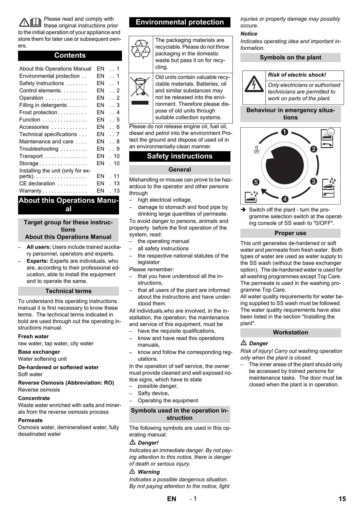
Behaviour in emergency situations
Please do not release engine oil, fuel oil, diesel and petrol into the environment Protect the ground and dispose of used oil in an environmentally-clean manner.
General Mishandling or misuse can prove to be hazardous to the operator and other persons through – high electrical voltage, – damage to stomach and food pipe by drinking large quantities of permeate. To avoid danger to persons, animals and property before the first operation of the system, read: – the operating manual – all safety instructions – the respective national statutes of the legislator Please remember: – that you have understood all the instructions, – that all users of the plant are informed about the instructions and have understood them. All individuals,who are involved, in the installation, the operation, the maintenance and service of this equipment, must be – have the requisite qualifications, – know and have read this operations manuals, – know and follow the corresponding regulations. In the operation of self service, the owner must provide cleaned and well exposed notice signs, which have to state – possible danger, – Safty device, – Operating the equipment
Switch off the plant - turn the programme selection switch at the operating console of SS wash to "0/OFF".
This unit generates de-hardened or soft water and permeate from fresh water. Both types of water are used as water supply to the SS wash (without the base exchanger option). The de-hardened water is used for all washing programmes except Top Care. The permeate is used in the washing programme Top Care. All water quality requirements for water being supplied to SS wash must be followed. The water quality requirements have also been listed in the section "Installing the plant".
Risk of injury! Carry out washing operation only when the plant is closed. – The inner areas of the plant should only be accessed by trained persons for maintenance tasks. The door must be closed when the plant is in operation.
Symbols used in the operation instruction
The following symbols are used in this operating manual: Danger! Indicates an immediate danger. By not paying attention to this notice, there is danger of death or serious injury. 몇 Warning Indicates a possible dangerous situation. By not paying attention to the notice, light
Use the keys "+" / "-" to select the menu
PARAMETER. Confirm the selection using "OK" The parameter window opens.
Setting the regeneration time
Head of base exchanger
Switch-off in case of emergency Switch off the plant, turn the emergency stop main switch to "0/OFF".
A B C D E F G H I Hardness sensor
Feedback Timer Base Exchanger Level Buffer Permeate Tank top Lack of water in RO unit Level Buffer Permeate Tank bottom RO inlet valve Timer RO pump
Level OK View 2: Operations messages
The plant runs automatically after start-up.
Settings for the base exchanger
No settings are required. The settings are done at the factory or by Customer Service. Manual regeneration Manual regeneration is required in the following cases: – Start-up of the plant, – after interruptions in operations on account of lack of salt. Start regeneration: Remove the lid of the control valve; you can see the programming unit Briefly press the red button; the regeneration process will start and run automatically. (Duration approx. 1 hour) Time-controlled regeneration The base exchanger cylinder needs to be regenerated once a week. We recommend that you carry out the regeneration during the operation-free night hours before the week-end operations. The procedure for setting the regeneration unit has been described in the following chapter “Setting the regeneration time“.
The control switches between View 1 and View 2 every 10 seconds. To switch to View 3, the ESC key must be pressed while View 1 is displayed. View 1: Internal control The upper line of digits in the display shows the inputs, the lower line shows the outputs of the control. – Black digit = inactive – Black background, white digit = active
A Display that controls are working
B Message softener unit (SO = softener) - 1 = Operations - 7 = Regeneration - E = Interruption C Messages for RO - 0 = Ready - 1 = Production - 2 = Final rinsing - 3 = Preliminary rinsing - 7 = Lack of water D Message for buffer permeate tank (TA = tank) - 1 = full - 3 = empty (retardation time is on or RO is in production) - 6 = Dry run delay is on - 7 = dry E Operating hours RO pump
Page 0 (switch-on time for regeneration)
Switch-on time Day 0...6 (Monday...Sunday) of the week Week 1 ... 5 of the month
Select the desired value by using the
"+"/ "-" keys Confirm the selection using "OK" The selected value blinks. Adjust the selected value by using the "+"/ "-" keys Confirm the setting using "OK". You can use the "+"/"-" keys to select additional values and set them as described above. Note "02:00 ON“ means that the regeneration will begin at 2:00 h. After all values have been set for the switch-on time, open the page for the switch-off time: Select page 0 (display shows "n.00“) with the "+/-“ keys. Confirm the selection using "OK" The selected value blinks. Press the "+" key. "n.01" is displayed. Confirm the setting using "OK".
View 3: a. Parameter settings
Press „Esc“ while View 1 is displayed. View 3 will be displayed.
Page 1 (switch-off time for regeneration)
Switching-off time Week 1 ... 5 of the month Day 0...6 (Monday...Sunday) of the week
Select the desired value by using the
Confirm the selection using "OK"
The selected value blinks. Adjust the selected value by using the "+"/ "-" keys Confirm the setting using "OK". You can use the "+"/"-" keys to select additional values and set them as described above. Note "02:01 OFF“ means that the regeneration will end at 02:01 h. Exit the window by pressing ESC. View 3 will be displayed. Exit view 3 by pressing ESC. Views 1 and 2 are displayed alternately. View 3: b. Set time/date Press „Esc“ while View 1 is displayed. View 3 will be displayed.
Use the keys "+" / "-" to select the menu
MISCELLANEOUS. Confirm the selection using "OK" The following window opens:
Setting the working pressure:
Preparation: – Measuring beaker min. 500 ml – Clock
Month Year Seconds Minutes Correcting the flow deviation in seconds per week G Hours Select the desired value by using the "+"/ "-" keys. Confirm the selection using "OK" The selected value blinks. Set the desired value by using the "+"/ "-" keys. Confirm the setting using "OK". You can use the "+"/"-" keys to select additional values and set them as described above. Exit the window by pressing ESC. View 3 will be displayed Exit view 3 by pressing ESC. Views 1 and 2 are displayed alternately.
First setting/ Controlling the production volume (when the pump is running):
Pull the red permeate hose from the permeate tank Collect water in measuring beaker and stop the time Calculate the production quantity Adjust the operating pressure and repeat the measurement until the correct output is generated. Inser the red permeate hose back into the permeate tank. Readjusting on account of fluctuating conditions: Set the operating pressure at the pressure regulation vale to the originally ascertained value
Filling in detergents
Select the menu CLOCK by using the
"+"/ "-" keys. Confirm the selection using "OK" The following window opens:
It is necessary to set the working pressure for two reasons: – Initial setting/ Controlling the production quantity – Readjusting on account of fluctuating conditions 몇 Warning Working pressure exceeding 14 bar will destroy the washers of the pressure pump; this can be detected from the bent covers. The plant settings are dependent on the temperature, i.e. depending on the temperature, different outputs will be achieved for different working pressures. Setting data RO-100
Use the keys "+" / "-" to select the menu
DATE/HOUR SETUP. Confirm the selection using "OK" The following window opens:
bar Adjust the pressure according to required output.
Salt tank of base exchanger
Fill softening salts
Risk of functional disturbances. While filling the softening salts, use only the softening salt in the tablet form listed in the chapter "Accessories". Open the salt tank. Fill the softening salt right until the top. Close the salt tank. Note An empty salt tank will cause disruption in operations! Fill the salt tank at the latest when water is visible in the salt tank while removing the lid. Filling the salt container to the top does not mean that there will be an increase in salt consumption. When the plant is functioning properly, the ratio of salt consumption to water consumption is constant. We recommend that you document the salt and water consumption in an operations log.
Restricted cleaning below –5 °C.
Frost safety of the plant until –20 °C. Below –20 °C, carry out "Bringing the plant to a standstill during frost conditions". Note The pre-requisites for frost protection are: – The operating type selection switch on the control panel of SS wash has been set to frost protection. Frost protection is deactivated in the position "0/OFF“. – Uninterrupted power and water supply must be ensured. Water supply must also be protected against freezing. – –
Note Plants without frost protection equipment must be brought to a standstill during frost conditions. The anit freeze equipment contains: – Thermal insulation – Hot blowers Note The following properties are ensured if the plant is equipped with frost protection mechanisms. – Unrestricted cleaning until –5 °C.
Instructions for assembling and installation are given in chapter "Installing the plant".
The hot air blower has been set correctly. All maintenance steps according to "Maintenance and Care" have been carried out correctly. The above-mentioned temperature details refer to the installation site. Temperature details provided in the weather report are not the deciding factors.
The fan heater does heat the inside of the equipment, in order to protect the equipment from frost.
1 Performance switch
2 Thermostat swith Adjustments: Output regulator in position “II” Thermostat regulator at the frost protection level (snow flake)
The frost protection mechanism works only when the plant has been switched on and the door is closed. The operating type selection switch of the SS Wash should not be set to "0/OFF". Similarly, there should be no interruption in the power supply to the plant. 몇 Warning! Dangers of burning, if fan heater does overheat. The incoming and outgoing air openings may not be covered up. Freezing damage because of not unforeseeable power interruption. When there is a power interruption the anti freeze equipment is not in operation.
Maintenance jobs before and during the frost period to get a better overview, the maintenance concerning the aniti freeze will summarized here. The checking of the anti freeze must be done yearly before the frost perod. In
section " maintenance and service" ought to be performed also in the winter time.
Maintenance not being done on time or from experts will mean, that there is no guarantee concerning frost damage.
Check interiors of the plant
Is the hot air blower working?
Check frost protection de- Turn the frost protection thermostat of SS wash in direction of "Check" until frosting period vices the frost protection devices are turned on. The hot air blowers of ABS WSO must start running. Further, at temperatures above 5 °C, the thermostat of the hot air blower must also turn up. Then turn the frost protection thermostat in an anti-clockwise direction until the stop. Then reset the thermostat of the hot air blower.
If the equipment is to be shut down, and there is not danger of frost, disconnect the water input, disconnect the power supply.
Blow out all water-carrying parts with oil-free compressed air.
In case of doubt, call Customer Service to carry out the shutdown operations.
Shutdown during frost period
Remove the RO membrane and store it under anti-freezing conditions. Separat the water supply between the base exchanger and the cooling of the high pressure pump of SS wash. Rinse the plant (without base exchanger) with an anti-frost solution. Rinse the base exchanger with concentrated salt solution. Shut down the SS wash during frost.
Flow-chart ABS WSO Hose connections to be established: SS Wash
ABS WSO A A B B C C D D E E F F EN
2 3 4 5 6 7 8 9 10 11 12 13 14 15 16 17 18 19
Base exchanger Salt tank Finest filter Active carbon filter Inlet valve Pressure switch - Water scarcity Pump Manometer for operating pressure RO membrane Flow meter for concentrate Valve for concentrate Valve for operating pressure Level switch Buffer tank is full Level switch Buffer tank is empty Buffer tank for permeate Locking valve for permeate tank Controls Solenoid valve block soft water/ permeate (built-in in SS wash) 20 Detergent container (Chem 3)
Functional description
If softened water is consumed, then fresh water flows through the base exchanger cylinder and is softened. If the residual hardness of the softened water exceeds a marginal value, the hard water sensor triggers a regeneration of the base exchanger cylinder. The base exchanger cylinder is regenerated using the brine from the salt tank. If the buffer tank of permeate is partially empty, then softened water flows from the base exchanger via – finest filter, – inlet valve, – Pump, – RO membrane, – to the buffer tank for permeate. The RO membrane separates the softened water in the permeate and concentrate. The permeate flows to the buffer container for permeate. A part of the concentrate is fed back for achieving better yield to the suction side of the pump. If the Top care programme is active, the SS wash is supplied with water from the buffer tank for permeate.
Test set A Order no. 6.768-004.0 for determining the fresh water hardness.
Test set B Order no. 6.768-003.0
For determining the residual hardness of the softened water.
Test set C Order no. 6.803-028
For determining the chlorine content based on the active carbon filter.
Lock grease Order no. : 6.288-116.0 Steel care product Order no. : 6.290-911.0 Water softening salt in form of tabletts order number: 6.287-016 25 kg, for option base exchanger
Monitoring and safety devices
Hard water sensor If the residual hardness of the softened water exceeds a marginal value, the hard water sensor triggers a regeneration of the base exchanger cylinder. Pressure switch - Water scarcity If there is no water, the plant is stopped in order to prevent dry running of the pump. Level switch Buffer tank is full Switches off the pump when the buffer tank for permeate is full. Starts the pump when the filling level in the buffer tank for permeate starts to sink. Level switch Buffer tank is empty Issues a signal to SS wash when the buffer tank for permeate is empty.
Technical specifications
Electrical connection Voltage
Output of connection to base module
Output of connection for frost protecton (optional)
Min. feed quantity (at 0.3 mPa and SS wash 50/10)
Max. water temperature
Max. hardness of fresh water
Hardness of softened water
° dH Water softening unit
Permeate output (at 15 °C water temperature) (lower output in case of cold water)
Max. operating pressure in new state (depending on temperature)
Desalination rate of membrane
Water temperature range
Max. ambient temperature
Residual hardness of feed water
° dH Max. conductivity of feed water for stain-free drying
Capacity of containers
Container for detergent
Buffer tank for permeate
Contents of permeate tank
Maintenance and care
Maintenance instructions The bases of a safe operating of the equipment is thr regularly maintenance according to the following maintenance plan. Use exclusively original parts of the manufacturer or those parts recommended by him like – parts and wearing parts, – accessories parts, – operating materials, – cleaning agents. Danger! There is danger of injury while working at the equipment.. Concerning all works
disconnect the input water, close the water supply,
disconnect the power supply, shut off the customer emergency main switch, and secure, that it can not be turned on. Who may perform maintenance? – operator Performances containing the notice "operator" may only be performed by instructed individualls, who are able to operate and service high pressure equipment.
Performances with the notice "maintenance" may only be performed by the Kärcher- Maintenance-Mechanics.
Maintenance contract
In order to guarantee a reliable operation og the equipment, we success, you signed a maintenance agreement. Please refer to you local Kärcher service department.
Maintenance schedule
Weekly or after 40 operating hours
Check pumps, fixtures and pipe systems for leaks.
Check salt stock in the salt tank
Is the salt level above the water level? If required, top up softening salts.
Check residual hardness of softened water
Take water from the swimmer tank for fresh water (SS wash) and
determine its residual hardness using test set B (order no. 6.768003) Target value: below 3 °dH Operator
Once, 1 month after start-up
Replace finest filter
Close the locking valve for fresh water (building site), unscrew the filter cup, replace the filter inlay, insert the new filter inlay and the filter cup back into place, open locking valve for fresh water.
After 160 operating hours or once a month
Check water level (approx. 5 ... 25 cm above the sieve plate).
Check for deposits; if required, empty the tank, clean it, fill it up with softening salts and start it up again. Risk of functional disturbances.
While filling the softening salts, use only the softening salt in the tablet form listed in the chapter "Accessories".
Depending on the chlorine content of the fresh water
Check active carbon filter
Take water sample at the rinsing valve of the active carbon filter.
Check using test set 6.803-028.0. If chlorine content exceeds 0.1 mg/kg chlorine, replace the filter inlay (once a year, see maintenance plan).
Half-yearly or after
1000 operating hours
Replace finest filter
Replace filter inlay; do not clean it.
Change filter inlay of active carbon filter
Close the locking valve for fresh water (building side), unscrew the filter cup and rinse it, replace the filter inlay through a new filter inlay, reinstall filter inlay and filter cup, open the locking valve for fresh water, slowly open the rinsing valve for active carbon filter and rinse the active carbon filter for 1 minute, close the rinsing valve for active carbon filter and start the plant.
Inform Customer Service. Check characteristic line (flow quantity and pressure).
Danger! There is danger of injury while working at the equipment.. Concerning all works disconnect the input water, close the water supply, disconnect the power supply, shut off the customer emergency main switch, and secure, that it can not be turned on.
Who may remedy faults?
Work designated with the sign “Operator” may only be carried out by persons who have been instructed in the safe operation and maintenance on the high pressure plant. Electricians
Persons with a professional training in the electro-technical area.
Customer Service Work designated with the sign “Customer Service” may only be done by the fitters of Kärcher Customer Service.
Base exchanger is not regenerating
Check power supply (fuse, plug, switch).
Hardness sensor (....) defective
No salt in the salt tank
Fill up salt, do not allow the salt level to fall below the water level.
Injector filter is blocked
Water flow to the salt tank is inadequate
Check the brine filling duration; clean the brine filling aperture, if required.
Rising pipe is leaky
Check rising pipe, pilot pipe
too much water in the water tank
wrong salt quantity setting
Check salt consumption and salt settings
Deposits in water inlet
Deposits in base exchanger
Clean valve and resin board
Rinsing aperture is blocked
Clean injector and filter
Foreign particles in the solenoid valve
Clean the solenoid valve, change the valve seat
Power failure while filling brine
Water inlet pressure is too low
Increase water pressure to at least 0.3 MPa (3 bar).
Rinsing aperture is blocked
Clean injector and filter
Leak inside the valve
Water remains hard after regeneration
too high salt consumption
Too much water in the salt tank
Brine is not getting sucked in
There is always water in the drainage, even after regeneration
Valve does not execute the correct cycles Check timer programme; replace the valve controls, if required
Foreign particle in the valve
Remove the valve control, take out the foreign particle, check valve in all the positions
Pump continuously goes on and off
Buffer tank for permeate is full
Wait until the permeate is consumed.
Level switch Buffer tank is full is defective
Start-up time of the control has not yet been completed
Pressure switch for water scarcity is defec- Check pressure switch; replace it, if required. tive
Regeneration of the base exchanger is running
Wait for regeneration to end.
No softened water is coming from the base exchanger
Check the base exchanger.
Finest filter or active carbon filter is dirty
Check filter; replace the filter inlay, if required
Regeneration of the base exchanger is in- Add salt, add water and wait for brine formation (ap- Operator/ complete prox. 2 hours); start regeneration, check the base ex- Customer changer, if required.
Pump starts only Too low mains water pressure after several rinsing cycles
Finest filter or active carbon filter is dirty Permeate output is too low; buffer tank of permeate is often empty
There are stains on the car paint during Top Care
(permeate has not been adequately demineralised)
Check mains water supply; open the inlet valve fully, if required.
Check filter; replace the filter inlay, if required
Water inlet temperature is too low
Measure the temperature of the softened water and compare it with the technical data.
Operating pressure is too low
Reset the operating pressure.
There are calcium or mineral deposits on the filter surface of the RO membrane.
Level switch Buffer tank is "full" is defective
There are bacteria or algae deposits on the filter surface of the RO membrane.
Rinse the membrane thoroughly for a long time; replace it if necessary. In future remember: Water is of potable quality; avoid long idling periods.
The mineral content of the softened water is too high
Check conductivity of softened water.
RO membrane has ruptured; defective sealing
Mixing of permeate and softened water
Comparison of conductivity of the permeate from the spray pipe and water from the buffer tank of permeate.
Caution Risk of injury and damage! Observe the weight of the appliance when you transport it. When transporting in vehicles, secure the appliance according to the guidelines from slipping and tipping over.
Caution Risk of injury and damage! Note the weight of the appliance in case of storage.
Installing the unit (only for experts)
Notice The equipment may only be installed by an – mechanic of Kärcher – or an from Kärcher authorized individual
Preparing the installation place
The following requirements are necessary in order to install the equipment: – Horizontal, plane surface with firm base admeasuring 845 x 725 mm next to the SS wash. – Water connection with pipe separator according to EN 1717m, for output data, see "Technical Data". Follow national regulations (DVGW in Germany). – By customer, lockable, access for the wash customer emergency - off- main switch. – Light at the washing area according to the national requirements, in order to assure safe working for the customer when dark. – Power and water supply according to the measuring sheet. – By operation in the winter, an isolated/ heated water supply sytem must be guaranteed. – Drain water shaft and required drain water disposal. – Drill fastening holes according to the measurement sheet.
Unpack the equipment
Unpack the equpiment and dispose of the packing material properly.
Aligning the unit and installing it
Line up the equipment on the level area. Fix with the material included. Use the inclosed spacer and set up the equipment horizontal.
Note Impurities in the inlet water can damage the unit. Kärcher recommends the use of a water filter (see "accessories"). To ensure frost protection of the plant, the water inlet must be protected against freezing (through insulation and accompanying heating). 몇 Warning Risk of damage to the plant if water supply is not of suitable quality. Use water only of potable quality as water supply to the plant. Quality requirements for tap water: Parameter
electrical conductivity
For connection values refer to technical specifications. Guide the inlet hose from the bottom through the opening in the plant and connect it to the base exchanger. Install the solenoid valves, chemical valve and the dosing valve in the SS wash and connect them (see chart in the chapter on Function).
Electrical connection
Guide the cable of the ABS anti-frost mechanism (hot air blower) through the opening of the plant and connect it in the electrical cabinet according to the circuit plan. Guide the enclosed cables through the opening in the plant, secure them with cable binders and connect them according to the circuit plan.
Carry out the following steps in the Control menu for releasing the ABS osmosis:
Press "OK" button for 1 seconds
Display: Data Adjust Press „<“ key Display: Warm Water Press „<“ key Display: Options Press "OK" key Display: Half Load: OFF/ON Press „<“ key Display: Osmosis: OFF Press "OK" key Display: Osmosis: OFF blinking Press „<“ key Display: Osmosis: ON blinking Press "OK" key Display: Osmosis: ON glows continuously Press "ESC" key twice Display: Save Parameter? Press "OK" key Display: DATA SAVING.... wait for approx. 5 seconds Press "ESC" key Settings completed
Turning the base exchanger on
Backwash Inser the overflow hoses of base exchanger and salt tank in the drainage pipe of the building. Fill the salt tank with water (approx. 10 cm) Do not add any salt yet! Open the locking valve in the inlet slowly and wait until the pressure tank is filled with water. Remove the covering lid of the control valve.
Press the programme button and select the function "Backwash" by turning the button in the direction of the arrow.
Water and air escapes through the drainage connection until the plant is completely deaerated.
Note: Restrict backwashing to the absolute minimum because otherwise the sensor measuring cell can get exhausted and this may necessitate a complete regeneration of the concerned exchange tank. Pull out the suction sieve fitted at the brine hose from the guide pipes in the salt tank. Press the valve flap (NR1) (directly behind the programming system) using a screw-driver. The air closure valve gets filled and air escapes through the suction sieve. When air no longer escapes from the suction sieve, release the valve flap. Insert the suction sieve back into the guide pipes.
Press the programme button and select the function "DRAW / SLOW RINSE“ (Regeneriation)" by turning the button in the direction of the arrow. Water level in the salt tank falls continuously. Note: The suction system needs to be deaerated if there is air formation in the air closure valve before the salt tank is empty (residual level in the salt tank, when empty, is approx. 7 cm) and the ball floating in the air closure glass falls down. Refill / Clean washing Press the programme button and select the function "REFILL" by turning the button in the direction of the arrow. The control valve automatically moves to the function "TREATED WATER“ (operations). The salt tank is filled with water. Filling the salt tank When the water level is correct, fill the salt tank with salt tablets according to DIN 19604 (also see chapter on Accessories). The plant is ready for operations when these jobs are completed. Conclude the start-up activities by doing a soft water test.
Start-up of the RO plant
Flow meter for concentrate
Valve for concentrate Valve for operating pressure
During first start-up:
Fill the membrane with initial tap water pressure (net it). Open the concentrate valve fully. Set low operating pressure at the operating pressure valve. Rinse the memrane for 10 ... 20 minutes (foam formation during this procedure is normal). During fresh start-up after shutdown: Let the rinsing run until there are no bubbles to be seen at the throughflow meter of the permeate. Open the operating pressure valve fully. Open the concentrate valve 2 by two turns. Setting the permeate quantity The permeate quantity depends on the operating pressure and water temperature. Note Set the pressure for permeate production. Set operating pressure at operating pressure valve to 1.0 MPa. Pull out the red hose from the buffer tank for permeate. Determine the permeate quantity per unit of time using the measuring beaker and stop clock or collection basin and weighing scale. Adjust the operating pressure at the operating pressure valve until the permeate quantity given below has been reached depending on the water temperature. 몇 Warning Risk of damage for pump and RO membrane. Do not set operating pressure at a level more than 1.4 MPa. Water temperature
Set concentrate quantity at the concentrate valve to the standard permeate output. The yield is then approx. 50%.
Set the clock for time-controlled regeneration of the base excahnger cylinder in the SS wash. Check the plant for leaks; tighten screws if required. Train the staff of the operator. Note Convince yourself that the operating staff has understood all the instructions clearly.
We hereby declare that the machine described below complies with the relevant basic safety and health requirements of the
EU Directives, both in its basic design and construction as well as in the version put into circulation by us. This declaration shall cease to be valid if the machine is modified without our prior approval. Product: Type:
Upgrade kit - water softener
Relevant EU Directives
2006/42/EC (+2009/127/EC) 2006/95/EC 2004/108/EC Applied harmonized standards EN 55014–1: 2006 + A1: 2009 EN 55014–2: 1997 + A2: 2008 EN 60335–1 EN 60335–2–2 EN 61000–3–2: 2006 + A2: 2009 EN 61000–3–3: 2008 Applied national standards The undersigned act on behalf and under the power of attorney of the company management.
CEO Head of Approbation
Authorised Documentation Representative
S. Reiser Alfred Kärcher GmbH Co. KG Alfred-Kärcher-Str. 28 - 40 71364 Winnenden (Germany) Phone: +49 7195 14-0 Fax: +49 7195 14-2212 Winnenden, 2011/07/01
The warranty terms published by our competent sales company are applicable in each country. We will repair potential failures of your appliance within the warranty period free of charge, provided that such failure is caused by faulty material or defects in fabrication. In the event of a warranty claim please contact your dealer or the nearest authorized Customer Service center. Please submit the proof of purchase.
6,5...9,5 max. 1000 μS/cm < 0,01 mg/l < 250 mg/l < 200 mg/l < 28 °dH < 0,2 mg/l < 0,05 mg/l < 0,02 mg/l < 240 mg/l < 0,1 mg/l
Regulator termostatu
AE Karcher FZE, P.O. Box 17416, Jebel Ali Free Zone (South),
Dubai, United Arab Emirates, +971 4 886-1177, www.kaercher.com AR Kärcher S.A., Urugguay 2887 (1646) San Fernando, Pcia. de Buenos Aires +54-11 4506 3343, www.karcher.com.ar
I Kärcher S.p.A., Via A. Vespucci 19, 21013 Gallarate (VA),
+39-848-998877, www.karcher.it IE Kärcher Limited (Ireland), 12 Willow Business Park, Nangor Road, Dublin 12, (01) 409 7777, www.kaercher.ie
JP Kärcher (Japan) Co., Ltd., Irene Kärcher Building, No. 2, Matsusaka-Daira 3-chome, Taiwa-cho, Kurokawa-gun, Miyagi 981-3408,
+81-22-344-3140, www.karcher.co.jp
AU Kärcher Pty. Ltd., 40 Koornang Road, Scoresby VIC 3179,
Victoria, +61-3-9765-2300, www.karcher.com.au
KR Karcher (Korea) Co. Ltd., 162 Gukhoe-daero, (872-2 SinjeongDong), Seoul, Korea
02-322 6588, A/S. 1544-6577, www.karcher.co.kr
MY Karcher Cleaning Systems Sdn. Bhd., 71 & 73 Jalan TPK 2/8,
Taman Perindustrian Kinrara, Seksyen 2, 47100 Puchong, Selangor Darul Ehsan, Malaysia, +603 8073 3000, www.karcher.com.my NL Kärcher B.V., Postbus 474, 4870 AL Etten-Leur, 0900-33 666 33, www.karcher.nl NO Kärcher AS, Stanseveien 31, 0976 Oslo, Norway, +47 815 20 600, www.karcher.no NZ Karcher Limited, 12 Ron Driver Place, East Tamaki, Auckland, New Zealand, +64 (9) 274-4603, www.karcher.co.nz PL Kärcher Sp. z o.o., Ul. Stawowa 140, 31-346 Kraków, +48-12-6397-222, www.karcher.pl RO Karcher Romania srl, Sos. Odaii 439, Sector 1, RO-013606 BUKAREST, +40 37 2709001, www.kaercher.ro RU Karcher Ltd. Service Center, Leningradsky avenue, 68, Building 2, Moscow, 125315 +7-495 789 90 76, www.karcher.ru SE Kärcher AB, Tagenevägen 31, 42502 Hisings-Kärra, +46 (0)31-577 300, www.karcher.se SGP Karcher South East Asia Pte. Ltd., 5 Toh Guan Road East, #01-00 Freight Links Express Distripark, Singapore 608831, +65-6897-1811, www.karcher.com.sg
GB Kärcher (U.K.) Ltd., Kärcher House, Beaumont Road,
Banbury, Oxon OX16 1TB, +44-1295-752-000, www.karcher.co.uk GR Kärcher Cleaning Systems A.E., 31-33, Nikitara str. & Konstantinoupoleos str., 136 71 Aharnes, +30-210-2316-153, www.karcher.gr HK Kärcher Limited, Unit 10, 17/F., Apec Plaza, 49 Hoi Yuen Road, Kwun Tong, Kowloon, ++(852)-2357-5863, www.karcher.com.hk HU Kärcher Hungaria KFT, Tormásrét ut 2., (Vendelpark), 2051 Biatorbagy, +36-23-530-64-0, www.kaercher.hu
TW Karcher Limited, 7/F, No. 66, Jhongijheng Rd., Sinjhuang City,
Taipei County 24243, Taiwan, +886-2-2991-5533, +886-800-666-825, www.karcher.com.tw UA Kärcher TOV, Kilzeva doroga, 9, 03191 Kiew, +380 44 594 7576, www.karcher.com.ua USA To locate your local dealer please visit our web site at http://www.karchercommercial.com or call us at 888.805.9852 ZA Kärcher (Pty) Ltd., 144 Kuschke Street, Meadowdale, Edenvale, 1614, +27-11-574-5360, www.karcher.co.za