
Arrifana 15 - Air Conditioning BLAUPUNKT - Free user manual and instructions
Find the device manual for free Arrifana 15 BLAUPUNKT in PDF.


| Product Type | Portable Air Conditioner |
| Model | Blaupunkt Arrifana 15 |
| Cooling Capacity | 15000 BTU/h (4.4 kW) |
| Heating Capacity | Not applicable (cooling only) |
| Energy Efficiency Ratio (EER) | 2.6 W/W |
| Power Supply | 220-240 V / 50 Hz |
| Power Consumption (Cooling) | 1700 W |
| Refrigerant | R290 (propane) |
| Air Flow Rate (Max) | 380 m³/h |
| Noise Level (Low/High) | 48 / 52 dB(A) |
| Dimensions (W x D x H) | 465 x 385 x 695 mm |
| Net Weight | 22 kg |
| Control Type | Remote control + Touch panel |
| Timer | 1-24 hours |
| Dehumidification Function | Yes, up to 1.5 L/h |
| Air Filter | Washable mesh filter |
| Installation | Window kit included (slider panel) |
| Condensate Drainage | Continuous drain hose or manual emptying |
| Maintenance | Clean air filter every 2 weeks |
| Safety Features | Auto restart, compressor delay, tip-over switch |
| Spare Parts / Repairability | Filters, remote, wheel kits available; rating 6/10 |
| General Information | Blaupunkt brand, model Arrifana 15, cooling-only portable AC |
Frequently Asked Questions - Arrifana 15 BLAUPUNKT
User questions about Arrifana 15 BLAUPUNKT
0 question about this device. Answer the ones you know or ask your own.
Ask a new question about this device
Download the instructions for your Air Conditioning in PDF format for free! Find your manual Arrifana 15 - BLAUPUNKT and take your electronic device back in hand. On this page are published all the documents necessary for the use of your device. Arrifana 15 by BLAUPUNKT.
USER MANUAL Arrifana 15 BLAUPUNKT
EN Portable air conditioner Instruction manual Page: 3-28
NAME OF EACH PART AND FUNCTION....5
INSTALLATION 6
CONTROL PANEL 13
WATER DRAINAGE METHODS....24
MAINTENANCE AND SERVICE....25
END OF SEASON OPERATION....26
TROUBLESHOOTING 27
INHALTSVERZEICHNIS
Use this air conditioner only as described in this instruction manual
- This air conditioner has been designed and manufactured to operate in a domestic situation only and should not be used for other purposes.
• The appliance is not intended for use by young children or infirm persons.
- Never use the air conditioner in damp rooms (eg. Bathrooms and laundries).
- If the power cord is damaged, it must be replaced.
- Do not pull on or place strain on the power cord when moving the appliance.
- Do not operate or stop the appliance by inserting or pulling out the power plug. User the on/off switch on the air conditioner control panel or the remote.
- Due to potential safety hazard do not use an extension cord or share the power supply outlet with other appliances.
- Do not rest hot or heavy objects on the appliance.
- Always unplug the unit from the power outlet before cleaning or maintenance operations, for example filter cleaning.
- Clean the filters at least once every two weeks.
- Do not splash the unit with water.
- Do not move the unit by pulling the exhaust hose attached to the back of the unit.
- Do not move air conditioner when it is operating.
- Do not use the unit with air outlet closed or covered.
- Before transporting the air conditioner, drain the water pan in accordance with instructions on page 13. After transportation, wait at least one hour before switching the unit on.
- The unit should be transported in a vertical position. If this is not possible, secure the unit at an angle, do not lay it horizontally.
- This appliance is fitted with a special safety device. When the compressor switches off, this device prevents it from switching on again for at least three minutes.
INTRODUCTION
This portable air conditioner can alter the room temperature and humidity. It has multiple functions of cooling, dehumidifying (drying) and fan ventilation and can be moved from room to room and transported from building to building easily.
Room temperature range should be under 18\~35°C to get this unit operational well and target room temperature can be adjusted from Remote Control under 18\~32°C.
GUIDELINES FOR OPTIMISING COOLING EFFECTIVENESS
The maximum effective room size is influenced by several factors including the amount and type of insulation, orientation of the room to the sun, amount of glass areas, type of curtains and ceiling height etc.
- The air conditioner is not designed to cool large open areas. Close all doors and windows in the room being cooled.
- Do not place the air conditioner in direct sun light. Close all curtains in the room being cooled.
- For maximum cooling (COOLING MODE), set the temperature 18 °C and the fan at HIGH. After approximately 3 minutes, the compressor will turn on (indicated by green LED marked 📁 on the control panel) and cooled air will come out of the air outlet. Cooled air will only come out of the air outlet when the LED on the control panel illuminated.
- In COOLING MODE the air conditioner will not cool unless the set temperature is below the existing room temperature.
- In COOLING MODE once the existing room temperature reaches the set temperature, the fan continues operating and the compressor switches on and off to maintain the set temperature within the room.
- Keep the exhaust hose as short and straight as possible
- Make sure the air intake and outlet grills are unobstructed.
- Clean the filters at least once every two weeks.
NAME OF EACH PART AND FUNCTION
FRONT (Fig. 1)
- Control panel
- Up/down manually adjusted air fins
- Air outlet
- Left/Right auto air swinging fans
- Rolling castor
- Cable (power cord and plug)

Fig. 1
BACK (Fig. 2)
- Hot air outlet grill
- Low air inlet grill
- High air inlet grill
- Power cord hooks
- Water tank/chassis
- Water tank drain outlet
- Plug

INSTALLATION
SELECTION OF INSTALLATION LOCATION (Fig.3)
Place the portable air conditioner in a flat location where the air inlets and outlets cannot be covered up. Place the unit no less than 50cm away from a wall or other obstacle.
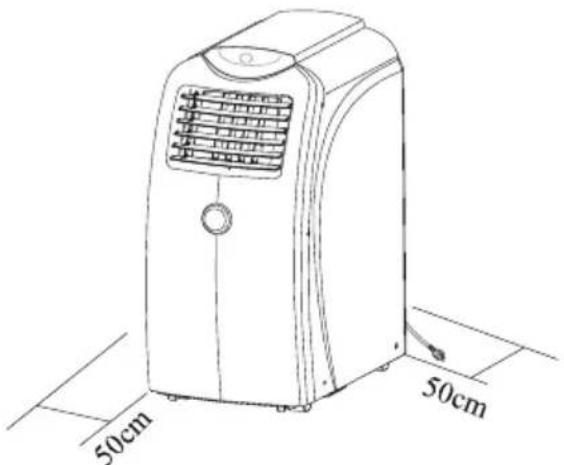
Fig. 3
INSTALLATION ACCESSORIES

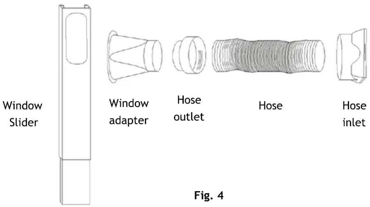
ASSEMBLY OF EXHAUST HOSE, HOSE INLET, HOSE OUTLET, WINDOW ADAPTOR AND WINDOW SLIDER
(Fig. 4)
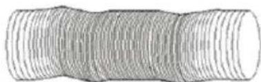
- Extend each end of the exhaust hose by about 8 cm and attach the hose inlet and hose outlet to opposite ends by rotation the inlet/outlet in a counter clockwise direction approximately 3 to 4 turns, making sure that the hose wire is well threaded into the hose inlet and outlet.
- Attach the window adaptor to the hose outlet by pressure fit
- Clip the window adaptor into the window slider. Take care to not break the tabs on the window adaptor when disconnecting from the window slider.
MOUNTING OF ASSEMBLED AIR EXHAUST HOSE
(Fig. 5)
- Take care not to damage the hose inlet when attaching/detaching at the back of the Air Conditioner.
- Slide the hose inlet (square end) in the direction indicated by the arrow onto the fixing lugs on hot air outlet grill at the back of the appliance. Install carefully and do not force.
- Place the hose outlet to the nearest window. The length of the air exhaust hose is between 600 mm to 1500 mm: use the minimum length when working.
- When mounting, try to keep the air exhaust hose horizontal and do not extend its length by attaching it to another hose as the reduces the cooling efficiency of the appliance.

ATTENTION
• The exhaust hose should be not longer than 1,5 meters.
• Never bend the exhaust hose excessively when the appliance is working
- Always keep the exhaust hose at its shortest length and as straight as possible when the appliance is working.
- Never move the appliance by pulling the air exhaust hose attached to the back of the appliance.
- Do not move the air conditioner when its operating.
Correct exhaust hose mounting shown below. If mounting in the wall, the height of the hole should be 40 cm \~ 130 cm (Fig. 6)

Fig. 6
If the air exhaust hose needs to be bent, the correct method is shown below(Fig. 7)

Fig. 7
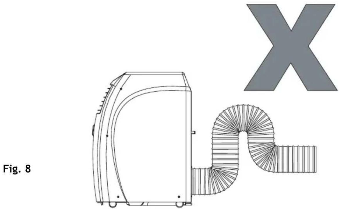
Incorrect or excessive bending of the exhaust hose will cause inefficient cooling and possible malfunction (Fig. 8)
WINDOW SLIDER KIT INSTALLATION (Fig. 9, Fig. 10, Fig. 11 and Fig. 12)
The window slider kit has been designed to fit most standard “vertical” and “horizontal” window applications. It may be necessary for you to improve/modify some aspects of the installation procedures for certain type of windows. Some window types may require the use of cardboard fillers and/or duct tape to install. Please refer to illustration for minimum and maximum window openings.

Window slider length
Min. 85cm
Max. 123cm

Fig. 9

Window slider length
Min. 85cm
Max. 123cm
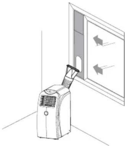
Fig. 10
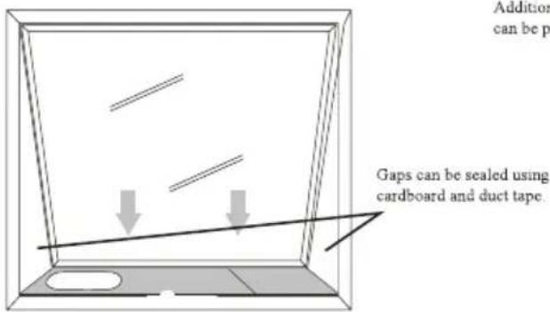
Window slider length
Min. 85cm
Max. 123cm
Gap can be sealed using
cardboard and duct tape.
Additional window sliders
can be purchased.
Standard door height 210cm

Window (Door) slider height
Max. 123cm
Fig. 11
Fig. 12
CONTROL PANEL
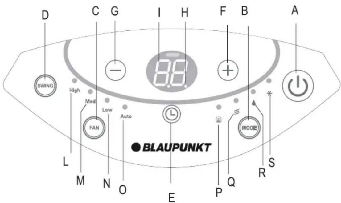
A. ON/OFF button.
B. MODE button to select modes of cooling/dry/fan.
C. FAN SPEED button to select fan speed of High/Med/Low/Auto.
D. SWING button to switch on/off left/right auto swing function.
E. TIMER button.
F. INCREASE button to increase temperature/time.
G. DECREASE button to decrease temperature/time.
H. TIMER INDICATOR LIGHT lights up and keeps flashing to indicate the timer is in operation.
I. LCD DISPLAY displays set temperature, timer hours or room temperature.
L/M/M/O. FAN SPEED LIGHTS of High/Med/Low/Auto.
P. COMPRESSOR OPERATING LIGHT illuminated when compressor is operating.
Q. FAN MODE LIGHT illuminated when in FAN mode.
R. DRY MODE LIGHT illuminated when in DRY mode.
S. COOLING MODE LIGHT illuminated when in COOLING mode.
The operating ranges for cooling and dehumidifying are 18° C \~ 32° C.
If the appliance is turned off during cooling or dry operation and restarted immediately, the unit will wait at least 3 minutes before restarting compressor.
POWER SUPPLY
- Do not connect the portable air conditioner to a power supply outlet which is also being used for other electrical appliances.
- Insert the power plug securely into the power supply outlet and turn power on/off button on the display panel (or remote) to start air conditioner.
ACCESSORIES
An accessory, in the form of two suction cups and a connecting string has been included to help store the remote control. To use this accessory, attach one suction cup to the remote control and the other to a conveniently located surface. Best results are achieved by wetting the suction cup before securing it to a hard flat surface.
COOLING MODE
- Press ON/OFF button to turn the appliance on
- Press MODE button to select COOLING mode
- Set the temperature with INCREASE/DECREASE buttons.
- To select fan speed press FAN SPEED button repeatedly until required speed is selected. (High/Med/Low/Auto). Auto fan speed adjusts the fan speed automatically between HIGH, MEDIUM and LOW settings according to variance between set temperature and room temperature.
- The set temperature will remain displayed in the control panel.
NB: In COOLING mode the appliance automatically removes excess moisture from the atmosphere.
NB: In COOLING mode the exhaust hose must be connecter to allow warm air to be expelled from the room being cooled.
DRY (DEHUMIDYFYING) MODE
- Keep the windows and doors closed for an effective dehumidification.
- When used as dehumidifier only, keep the air exhaust hose disconnected from the back of the unit.
- Press ON/OFF button to turn the appliance on.
- Press MODE button to select DRY mode, the fan speed will always be at Auto and can not be adjusted in DRY mode and the control panel will display “dh”.
- Compressor light will be permanently illuminated in this mode after approximately 3 minutes.
FAN MODE
- Press ON/OFF button to turn the appliance on
- Press MODE button to select FAN mode.
- To select fan speed press FAN SPEED button repeatedly until the required speed is selected (HIGH, MED, LOW). The fan speed AUTO can not be selected in FAN mode.
NB: In FAN mode the exhaust hose does not need to be connected.
SETTING THE TIMER
This timer can be used to delay the appliance start up or shutdown. This avoids wasting electricity by optimizing operating periods.
PROGRAMMED SHUTDOWN
- With the appliance on press TIMER button the time remaining until shutdown is displayed on LCD.
- Set the time when you want the appliance to switch off with INCREASE and DECREASE buttons (from 30 minutes to 24 hours).
• During the first ten hours you can select half hour intervals. For times
longer than ten hours, one hour intervals can be selected.
- Press TIMER button again to confirm the timer setting, the TIMER INDICATOR LIGHT lights up and keeps flashing to indicate the timer is activated.
• At the end of the set time the appliance switches off automatically.
• To cancel the TIMER setting press TIMER button again.
PROGRAMMED STARTUP
- Turn on the Appliance and select the required mode for example: COOLING 25°C, fan speed HIGH.
- Press ON/OFF button to switch into STANDBY.
- Press TIMER button on the time is displayed on LCD display.
- Set the time remaining until startup with INCREASE and DECREASE buttons (from 30 minutes to 25 hours).
- During the first ten hours you can select half hour intervals. For times longer than ten hours one hour intervals can be selected.
- Press TIMER button again to confirm the timer setting. The TIMER INDICATOR LIGHT lights up and keeps flashing to indicate the timer activated. The time remaining (in hours) will also be shown on LCD display.
- At the end of the set time the appliance switches on automatically and operates in the selected mode for example COOLING 25°C, fan speed HIGH
- To cancel the TIMER setting press the TIMER button again.
REMOTE CONTROL
How to insert the batteries
Remove the cover from the battery compartment, by sliding it in the direction of the arrow.
Insert the new batteries, ensuring that the (+) and (-) directions are correct.
Refit the cover by sliding it into place.

Use 2 LRO 3 AAA (1.5 V) batteries. Do not use rechargeable batteries. Replace the old batteries with new ones of the same type when the display is no longer legible. The remote control batteries must be disposed of in accordance with the applicable laws in force in the country of use.
Refer the right side picture:
- When you insert the batteries for the first time in the remote control or if you change them, you will see a DIP switch under the back cover.
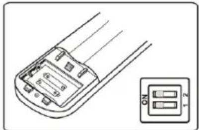
| DIP position | Function |
| °C | The display is adjusted in degree celsius. |
| °F | The display is adjusted in degree fahrenheit. |
| COOL | The remote control is adjusted in only cooling mode. |
| HEAT | The remote control is adjusted in only heating mode (Heating mode not available for this model) |
- BE CAREFUL: After adjusting the function, you need to take out the batteries and repeat again procedure described above.
If the remote control is not used for long periods, remove the batteries.
CORRECT USE
- Point the remote control towards the front of the air conditioner (see Fig. 13)
- Maximum distance approximately 7 meters (without any obstacles between the remote control and receiver).
- Do not drop remote control expose it to direct sunlight or leave it near sources of heat.

Fig. 13
FUNCTIONS OF REMOTE CONTROL
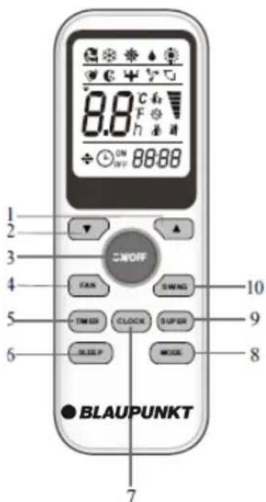
| No | Button | Function |
| 1. | ▲ | Increase the temperature or time by 1 unit. |
| 2. | ▼ | Decrease the temperature or time by 1 unit. |
| 3. | ON/OFF | To switch the conditioner ON or OFF. |
| 4. | FAN | To select the fan speed of HIGH/MED/LOW/AUTO. |
| 5. | TIMER | To set automatic switching-on/off. |
| 6. | SLEEP | NOT AVAILABLE IN THIS MODEL |
| 7. | CLOCK | When you press this button the time will be flickerin then through ▲ and ▼, you can adjust the time (one time you press, one minute you adjust; and if you continue to press, the time change rapidly), after adjusting to your required time, please press this button again to fix the time. |
| 8. | MODE | To select the mode of operation. |
| 9. | SUPER/TURBO | In cooling mode, press this button, the unit give the maximum cooling temperature. |
| 10. | SWING | To activate or deactivate of the movement of the „DEFLECTORS“. |
REMOTE CONTROL DISPLAY

Meaning of the symbols on the LCD display:
| Nr. | Symbol | Meaning |
| 1. |  | FEEL indicator (not available for this model) |
| 2. | [48YW] | COOLING indicator |
| 3. |  | DEHUMIDIFYING indicator |
| 4. | [806C] | FAN ONLY OPERATION indicator |
| 5. |  | HEATING indicator (not available for this model) |
| 6. | [X070] | SIGNAL RECEPTION indicator |
| 7. |  OFF OFF | TIMER OFF indicator |
| 8. | [H02C]ON | TIMER ON indicator |
| 9. |  IT IT | AUTO FAN indicator |
| 10. | [OWHB] | LOW FAN SPEED indicator |
| 11. | [S112] | MEDIUM FAN SPEED indicator |
| 12. | [S212] | HIGH FAN SPEED indicator |
| 13. | [S214] | SLEEP indicator (not available for this model) |
| 14. | [S226] | SWING indicator |
| 15. | [S236] | SUPER indicator |
| 16. | [T360] | BATTERY indicator |
| 17. | [834T] | CLOCK indicator |
USING THE REMOTE CONTROL UNIT
MODE COOLING MODE
- Press the ON/OFF button to turn the appliance on.
- Press the MODE button to * select icon.
- Set the temperature using ▲ or ▼ button.
- To set fan speed press the FAN button repeatedly until the required speed is selected (HIGH, MED, LOW, AUTO).
NB: In COOLING mode the appliance automatically removes excess moisture from the atmosphere.
NB: In COOLING mode, the exhaust hose must be connected to allow warm air to be expelled from the room being cooled.
MODE DRY MODE
- When used as dehumidifier only, keep the air exhaust hose disconnected.
- Press the ON/OFF button to turn the appliance on.
- Press the MODE button to select

icon, the fan speed will always be at AUTO and cannot be adjusted in DRY mode.
MODE FAN ONLY OPERATION MODE
- Press the ON/OFF button to turn the appliance on.
- Press the MODE button to ✦ select icon.
- To select fan speed, press the FAN button repeatedly until the requires speed is

selected (HIGH, MED, LOW). Fan speed AUTO can not be selected.
NB: In FAN mode, the exhaust hose does not need to be connected.
CLOCK
CLOCK FUNCTION
- When you press „CLOCK button the time will be flickering.
- Then through ▲ and ▼ you can adjust the time. One time you press, one minute you adjust; and if you continue to press the button the time change rapidly.
• After adjusting to your required time, please press CLOCK button again to fix the time.

SUPER
SUPER FUNCTION
Ideal for the summer to cool rooms rapidly.
To set this mode:
- Press the SUPER button.
The appliance operates in cool mode at maximum fan speed and cooling temperature. While this
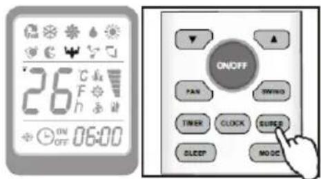
function is active, you don't need to set the temperature and fan speed manually
if want the most powerful cooling.
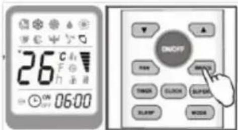
SWING
SWING FUNCTION
- Press the SWING button.
PROGRAMMING THE TIMER
The appliance can be programmed to start up and shut down when desired.
Programming start up
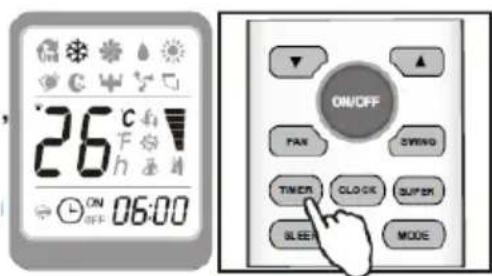
To program the time start, the appliance should be off.
- Press TIMER button, set the temperature with pressing the key ▲ or ▼. Press TIMER again, set the time with pressing the key ▲ or ▼. Press the key more times till on the display you can read the timed start.
IMPORTANT!
Before proceeding with the timed start:
- Program the working mode with the MODE button and the fan speed with the FAN button. - Switch the conditioner off with the ON/OFF button.
Note: To cancel the set function, press the TIMER button again.
Note: In case of power off, it is necessary to set TIMER ON again.
PROGRAMMING SHUTDOWN
The timed stop is programmed with the appliance on. Press TIMER button, set the time pressing the key ▲ or ▼, press the key more times till on the display you can read the time which passes between the programming and the timed stop.
Note: To cancel the set function, press the TIMER button again.

Note: In case of power off, it is necessary to set TIMER OFF again.
Note: While the time was right settled, the TIMER function of this remote(clock function) can set half hours.

WATER DRAINAGE METHODS
WATER DRAINAGE
This air conditioner is equipped with the very latest MIST technology which means the water tank never fills. This has been verifies by independent testing conducted both in Australia and overseas under extremely humid conditions. Water drainage will generally only be required at the end of the season (see End of Season Operations).
However the mist technology does not operate when the unit is in dehumidifying (dry mode). Thus, the tank may require emptying on occasions when operating for long periods in this mode.
As safety measure to positively prevent water spillage, the air conditioner is equipped with a fail safe device. If the water tank fills the unit will completely stop including both fan and compressor.
The control panel LED displays “Ft” as mentioned in the Section on “Self-Diagnosis”. The compressor and fan will not restart until the tank has been drained.
Before draining the water tank (pan) take care not to move the air conditioner as water may spill onto the floor.
Turn the air conditioner off using the on/off switch on the unit or remote control. Then drain the water tank by unplugging the drain outlet and allowing the water to flow onto the drain pan. The drain pan will not hold the full contents of the water tank. A number of fills of the drain pan are required. It may be easier (after 3 or 4 pans have been drained in order to avoid accidental spillage when shifting the air conditioner) to wheel the unit outside, remove the drain plug and drain the water onto the ground.
The water tank is considered sufficiently drained when no more water flows from the drain outlet.
Restart the air conditioner by pressing the on/off button. Ensure that the unit is in COOL or DRY mode. The compressor will start approximately 3 minutes after the
unit is switched on.
NOTE: To completely drain all water from the water tank, tilt the unit by lifting is slightly upwards from the front until no more water drains from the outlet.

MAINTENANCE AND SERVICE
MAINTENANCE METHODS
- Before undertaking cleaning or maintenance, turn the appliance off by pressing the On/OFF button, then always unplug the appliance from the power supply outlet.
- Do not use chemical solvent to clean the surface of the unit. Never spray insecticides or similar in the vicinity of the unit.
- Clean the surface of the unit with a damp cloth, then dry with a duster or similar.
CLEANING THE AIR FILTER
Clean the dust filter once every two weeks of operation. This will kepp the air conditioner working efficiently.
- Slide out the air filter from the side as shown below
- Wash the air filter by immersing it gently into warm (about 40 °C or 104°F) water with a dishwashing detergent.
- Rinse the filter of detergent and dry it thoroughly in a shaded place.
- Insert the filter back into the original positions.

- Switch off the unit and disconnect the plug from the power supply outlet.
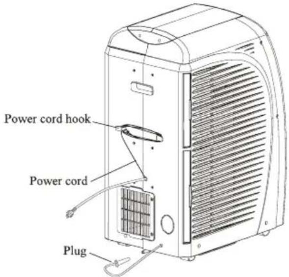
- Remove the plug from the drain outlet to drain the water onto the drain pan and dispose of the water. Tilt the unit by lifting it at the front to ensure all water is removed from the water tank. Then operate the unit in fan mode for half a day until the pipe is dry.
• Wind the cable around the cable hooks on the back of the appliance. - Wrap the appliance with the plastic bag and keep it in a dry place.
TROUBLESHOOTING
Before seeking repair or service, please check the following.
| PROBLEM | CHECK | ACTION |
| No power to air conditioner | Is A/C plugged into power supply outlet?Has fuse blown (circuit breaker switched off) or A/C switched off? | Insert power plug securely into power supply outlet and turn power on.Turn A/C off, replace fuse wire (or turn on circuit breaker) turn A/C back on. |
| Power to air conditioner, but unit does not operate | Is timer on? | Wait for timer to count down or cancel timer setting by pressing TIMER button. |
| Air conditioner does not cool after turning on | Is compressor light illuminated? | Wait 3 minutes from turning on, safety device prevents compressor (which provide cooling) being turned on for about 3 minutes. |
| The compressor and fan has stopped. | Is “Ft” displayed on LCD? | Drain water |
| Air conditioner not cooling satisfactorily | Has the temperature been set low enough?Air exhaust hose blocked?Air exhaust hose bent over?Standard air exhaust hose has been extended longer than 5m?Air exhaust hose detached?Window/door opened?Air inlet/outlet blocked?Air filters dirty?Fan speed set at low?Cooling power not enough for the conditions of area or room? | Reduce temperature settingsClear blockageAlways keep the hose at its shorted length and as straight as possibleRemove extension always keep standard hose length less than 1.5 meters.Connect the hoseClose the windows/doors to room being cooled.Clear blockageClean air filterSet suitable higher speedEnsure A/C is suitable for conditions of area and room. |
| Air conditionervibrates | Is it leaning or unbalanced? | Place on level floor |
| Lt/Pf/Ftappears on the display | See self-diagnosis section |
Note: In COOLING MODE, the compressor is switched on when cooled air comes out of the air outlet and the compressor light on the control panel is illuminated. In DRY MODE, the compressor operates continuously and compressor light is permanently illuminated.
SELF DIAGNOSIS
The appliance has a self diagnosis system to identify a number of malfunctions. Follow the proposed action when the code is displayed.
| LE | (LOW TEMPERATURE)Frost protection | When the appliance is operating in dehumidifying mode, this device prevents the formation of ice. The appliance starts up again automatically when the defrosting process is complete. |
| PF | (PROBE FAILURE)Sensor damaged | If this is displayed, contact with service center. |
| FE | (FULL TANK)The water tank is full | Empty the internal tank, see the section on “Water Drainage Method”. |
Mobiles Klimagerät
Arrifana 15
BAC-PO-0015-C06D
Bedienungsanleitung

BLAUPUNKT
Competence Center Aircon
MATEKO Sp. z o. o.
ul. Przyleśna 15
Michałów - Grabina
05-126 Nieporet
e-mail: service@mateko.pl
www.blaupunkt.com
Dankeschön
Abb. 3
INSTALLATIONSELEMENTE


VORSICHT

Abb. 7
Abb. 9

Abb. 10
Meaning of the symbols on the LCD display:
ENDE DES GEBRAUCHSSAISONS
Competence Center Aircons
MATEKO Sp. z o. o.
ul. Przyleśna 15
Michałów - Grabina
05-126 Nieporet
e-mail: service@mateko.pl
www.blaupunkt.com
PRZEPISY I ZASADY BEZPIECZEŃSTWA
Rys. 1
TYL (Rys. 2)
WYBÓR MIEJSCA INSTALACJI (Rys. 3)
Rys. 3
ELEMENTY INSTALACYJNE

MONTAŻ WEŻA WYDECHOWEGO, WLOTU WEŻA, WYLOTU WEŻA, ŁĄCZNIKA OKIENNEGO ORAZ SUWAKA WENTYLACYJNEGO. (Rys. 4)
UWAGA
Rys. 7
INSTALACJA SUWAKA WENTYLACYJNEGO
Rys. 9

Rys. 10


FUNKCJE PILOTA ZDALNEGO STEROWANIA

UTRZYMANIE I KOSERWACJA
METODY KONSERWACJI
KONIEC SEZONU UŻYTKOWANIA
English (GB) : Disposal of Waste Equipment by Users in Private Households in European Union. This symbol on the product or on its packaging indicates that this product must not be disposed of with your other household waste. Instead, it is your responsibility to dispose of your waste equipment by handing it over to designated collection point for the recycling of waste electrical and electron equipment. The separate collection and recycling of your waste equipment at the time of disposal will help to conserve natural resources and ensure that is recycled in a manner that protects human health and the environment. For more information about where can you drop off your waste equipment for recycling , please contact your local city office, your household waste disposal service or the shop where you purchased the product. Where batteries or accumulators are collected together with waste electrical and electronic equipment on the basis of Directive 2002/96/EC, batteries or accumulators shall be removed from the collected waste electrical and electronic equipment.
| B | AC | PO | 00 | 15 | C06D |
| B: | AC: Air | PO: Portable | Heating | Cooling | Internal |
| Blaupunkt | Conditioner | capacity: in kBTU/h | capacity: in kBTU/h | number |
KUNDENHOTLINE
Kundenhotline
AT:
Tel.+43-1-9717059
E-Mail: office@esc-service.at
DE:
Tel. 00 800 888 00 444
E-Mail:
blaupunkt-service-de@teknihall.com


- INHALTSVERZEICHNIS
- INTRODUCTION
- GUIDELINES FOR OPTIMISING COOLING EFFECTIVENESS
- NAME OF EACH PART AND FUNCTION
- FRONT (FIG. 1)
- BACK (FIG. 2)
- INSTALLATION
- SELECTION OF INSTALLATION LOCATION (FIG.3)
- INSTALLATION ACCESSORIES
- ASSEMBLY OF EXHAUST HOSE, HOSE INLET, HOSE OUTLET, WINDOW ADAPTOR AND WINDOW SLIDER
- MOUNTING OF ASSEMBLED AIR EXHAUST HOSE
- (FIG. 5)
- ATTENTION
- WINDOW SLIDER KIT INSTALLATION (FIG. 9, FIG. 10, FIG. 11 AND FIG. 12)
- CONTROL PANEL
- POWER SUPPLY
- ACCESSORIES
- COOLING MODE
- DRY (DEHUMIDYFYING) MODE
- FAN MODE
- SETTING THE TIMER
- PROGRAMMED SHUTDOWN
- PROGRAMMED STARTUP
- REMOTE CONTROL
- HOW TO INSERT THE BATTERIES
- REFER THE RIGHT SIDE PICTURE
- CORRECT USE
- FUNCTIONS OF REMOTE CONTROL
- REMOTE CONTROL DISPLAY
- USING THE REMOTE CONTROL UNIT
- MODE COOLING MODE
- MODE DRY MODE
- MODE FAN ONLY OPERATION MODE
- CLOCK
- CLOCK FUNCTION
- SUPER
- SUPER FUNCTION
- SWING
- SWING FUNCTION
- PROGRAMMING THE TIMER
- PROGRAMMING SHUTDOWN
- WATER DRAINAGE METHODS
- WATER DRAINAGE
- MAINTENANCE AND SERVICE
- MAINTENANCE METHODS
- CLEANING THE AIR FILTER
- TROUBLESHOOTING
- SELF DIAGNOSIS
- MOBILES KLIMAGERÄT
- ARRIFANA 15
- BAC-PO-0015-C06D
- BEDIENUNGSANLEITUNG
- BLAUPUNKT
- DANKESCHÖN
- INSTALLATIONSELEMENTE
- VORSICHT
- ENDE DES GEBRAUCHSSAISONS
- PRZEPISY I ZASADY BEZPIECZEŃSTWA
- TYL (RYS. 2)
- ELEMENTY INSTALACYJNE
- MONTAŻ WEŻA WYDECHOWEGO, WLOTU WEŻA, WYLOTU WEŻA, ŁĄCZNIKA OKIENNEGO ORAZ SUWAKA WENTYLACYJNEGO. (RYS. 4)
- UWAGA
- INSTALACJA SUWAKA WENTYLACYJNEGO
- FUNKCJE PILOTA ZDALNEGO STEROWANIA
- UTRZYMANIE I KOSERWACJA
- METODY KONSERWACJI
- KONIEC SEZONU UŻYTKOWANIA
- KUNDENHOTLINE
Brand : BLAUPUNKT
Model : Arrifana 15
Category : Air Conditioning