
HAK 380 - Mixer Ecler - Free user manual and instructions
Find the device manual for free HAK 380 Ecler in PDF.


| Product type | Mixing desk |
| Brand | Ecler |
| Model | HAK 380 |
| Dimensions (W x D x H) | 300 mm x 250 mm x 100 mm |
| Weight | 3 kg |
| Power supply | Mains 230 V, 50 Hz |
| Number of channels | 2 stereo channels + microphone |
| Equalization | 3-band (bass, mid, treble) |
| Inputs | 2 stereo line inputs (RCA), 1 XLR microphone input |
| Outputs | 1 main output (XLR and RCA), 1 headphone output (6.35 mm jack) |
| Main functions | Audio mixer, equalizer, microphone preamp, headphone output |
| Care and cleaning | Use a soft, dry cloth. Do not use abrasive products. |
| Safety | Disconnect before cleaning. Do not expose to moisture. |
| Spare parts and repairability | Contact Ecler after-sales service for spare parts. |
| General information | Compact mixing desk for DJ or light sound reinforcement. |
Frequently Asked Questions - HAK 380 Ecler
User questions about HAK 380 Ecler
0 question about this device. Answer the ones you know or ask your own.
Ask a new question about this device
Download the instructions for your Mixer in PDF format for free! Find your manual HAK 380 - Ecler and take your electronic device back in hand. On this page are published all the documents necessary for the use of your device. HAK 380 by Ecler.
USER MANUAL HAK 380 Ecler
3.1. Placement and mounting 05
3.2. Input signal sources 05
3.2.1.Turntables 05
3.2.2. Microphones 06
3.2.3. CD Players, Mini-Disc, Tape... 06
3.2.4. Direct access to the main mix 06
Congratulations! You are the owner of a genuine ECLER professional equipment. The HAK380 Performance Mixing Instrument has been carefully researched in collaboration with leading performers, developed with the highest quality components, and efficiently manufactured under strict quality controls.
The HAK380 is a dedicated Hip-Hop mixer. Its characteristics make it specially suitable for scratching, beat juggling and other "Turntablist" techniques. Even so, the HAK380 can be used as well for other styles like, e.g. House, Trance, Drum'n'Bass or Techno.
To obtain maximum functionality and efficiency from this unit, it is important to read and respect the considerations included in this manual before connecting the unit. To ensure an optimal functionality of the unit, maintenance and possible repairs should only be realized by our Authorized Technical Services.
This apparatus must be earthed through its mains cable.
Do not expose the unit to rain or water splashes, and do not place liquid containers or incandescent objects like candles on top of the unit. Do not obstruct the ventilation shafts with any kind of material.

Any change in the configuration of the unit must be carried out by a qualified technician. Should any connection / disconnection task be done, always disconnect the unit from the mains supply.

CAUTION: RISK OF ELECTRIC SHOCK. DO NOT OPEN.
2. INTRODUCTION
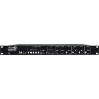
The HAK380 is a four way mixer, two of them with faders (LINE or PHONO), a complete microphone way and the Session-Mix function. The unit has balanced outputs with XLR3 and TRS connections. The mounted ECLER switched power supply is oversized in order to improve the dynamic range and offers great versatility for the power connection. This power supply is able to operate with voltages with a margin from 90 to 264V with frequencies between 47 and 63Hz without need of internal adjustments (it is suitable for any voltage of any country in the world).
The HAK380 has an inductive ETERNAL crossfader, using a XF concept designed by ECLER (Patent Pending), which does not require any contact. The ETERNAL magnetic field system, in combination with an effective, guided sliding system, gives the ETERNAL crossfader a very soft movement, an instantaneous “cut in time” and a nearly unlimited lifetime. The ETERNAL system also allows to include the REVERSE function, the transition curve function, which is an electronic system to adjust the CUT IN TIME, and the revolutionary SCRATCH CUE function.
The new ECLER faders combined with a high quality VCA system offer a longer lifetime in comparison with conventional faders and the possibility to invert the attenuation curve (adjustment for "mixing" or "scratching"). In the ECLER tests, the time-to-live of these faders was more than 4.000.000 operations.
The HAK380 has 2+2 mixable ways (channel 1 and channel 2, session, mic) with 5+1 stereo inputs and a microphone input (2 phono, 2 line, 1 session, 1 microphone). The two main channels have a three way equalizer with "OFF" function, gain control, a sliding balance control and a PFL function for visual monitoring with the vu-meter and audible monitoring with headphones.
3. INSTALLATION
3.1. Placement and mounting
The first thing to take into consideration when placing your HAK is your comfort and an easy access to all the connections. The HAK380 is basically conceived as a tabletop mixer and its usual placement will be between two vinyls or CD players. The optional metallic side profiles kit allows you to firmly fix your HAK to the surface over which it is placed or over its own profiles (Fig.1). These profiles also allow to tilt the mixer's position for an easier operation.
Because of the high gain of the PHONO and MICROPHONE inputs, always try to place the mixer as far away as possible from noise sources (dimmers, engines, etc.) and mains wires. For the very same reason, and under any circumstance, you should never remove the unit's metallic cover.
The power consumption of the HAK is very low, so they don't need any cooling, but you should avoid extreme temperatures and the atmosphere should be as dry and dustfree as possible.
The HAK380 operates now with a new universal input power supply "Switching Power Supply" and can perfectly works without any internal modification from 90V to 264V – 47 to 63Hz. Make sure that the mains-wire is far away from the signal-cables in order to avoid any possible audio hum.
In order to protect the unit from an eventual electrical overload it carries a 500mA fuse. Should it ever blow up, unplug the unit from mains and replace it with an identical one. If the new fuse blows again contact immediately with our authorized technical service.

ATTENTION: NEVER SHORT-CIRCUIT THE SECURITY PATH NOR USE A HIGHER VALUE FUSE.
CAUTION: Fuse substitutions have to be performed by a qualified technician.
3.2. Input signal sources
3.2.1. Turntables
Turntables need a phono cartridge and an intact needle. Consider using specialized cartridges and needles for hard scratching application. Remember also to replace the needle approximately every 500 hours of use. Turntables must be fitted with magnetic cartridges of 5.6 to 140mV nominal output level. The PHONO inputs (12) of the HAK380 have a very good headroom so they can accept high output level cartridges. If you use low output, moving coil cartridges, you will need to use an external preamplifier, placed as near as possible to the turntable and connected between the cartridge and the mixer.
Please take care on the correct assignment of channels to the Phono inputs and that the turntables ground cable is connected to the HAKs GND (4).
3.2.2. Microphones
The microphone connector is a "COMBO" connector (9). This connector combines an XLR-3 connector and a 14 " TRS connector. These inputs accept balanced connections. These connections have to be made in the following way:
| XLR 3 | Stereo Jack | |
| HOT or direct signal | Pin 2 | Tip |
| COLD or inverted signal | Pin 3 | Ring |
| GROUND | Pin 1 | Sleeve |
Low impedance (200 to 600Ω) monophonic microphones must be used. For non balanced microphones we recommend monophonic jack plugs although stereo ones are also suitable if the ring is short-circuited to the sleeve. An XLR connector could also be used for non-balanced signals if pin 1 and 3 are short-circuited.
Micro channel is equipped with an INSERT connection (11) in order to insert external effect units only to this channel. The insertion is made by using a stereo jack, the tip of the jack is the send and the central ring the return.
The HAK380 has phantom power for condenser microphones. An internal jumper allows to inhibit the operation of the phantom power. The MIC input is set to "phantom ON" by factory. See fig.2.
3.2.3. CD Players, Mini-Disc, Tape...
Line level devices such as Compact Discs, Tape recorders, Mini-Disc or Video Recorders can be connected to any LINE input (13). Any of these inputs can handle high level signals. Sensitivity of LINE inputs is rated at -10dBV. This allows connection of virtually any audio source.
3.2.4. Direct access to the main mix
The HAK380 has a SESSION input (21), which allows the connection with other mixers. By doing so, multiple mixers can be "hung" in series (cascade). This option is very useful in the "Team Battle" mode.
This can be done using the switch (3) located at the back panel and the vu-meters led will light up immediately. Although the switching noise produced by the HAK380 is very low and almost inexistent when starting up the HAK with the main faders down, we highly recommend the "safe power-up sequence", which means that you should switch on your audio devices in the following order:
- Sound sources
- Mixer, equalizers, active filters
- Finally, power amplifiers.
Powering off should be done by following the exact reverse sequence in order to avoid any possible damage to the loudspeakers.
4.2. Monitoring System
The HAK380 is equipped with a pre-listening system which allows monitoring of the FX (effects return), PGM (program) and PFL (pre-fader monitoring) signals with the vu-meter and/or with the headphones.
- SCRATCH CUE switch (36). When off, the signal selected with FX-PGM-PFL switch (35) can be seen and heard. When on, this switch is inhibited and the left vu-meter shows the sum L+R from PFL INPUT 1, while the right vu-meter shows the sum L+R from PFL INPUT 2 and with the headphones PFL INPUT 1 and PFL INPUT 2 can be heard in stereo, depending on the positions of the balance control (40) and the crossfader (49). This allows pre-listening the SCRATCH done with the crossfader.
- FX-PGM-PFL switch (35). Allows visual and audible monitoring of the effects return signal (FX), the program signal (PGM) and the pre-fader signal (PFL). When FX or PGM is selected, both, visual and audible monitoring, are in stereo. If PFL is selected, the operation of the monitoring system is the same as for the SCRATCH CUE switch.
4.3. Channel gain
All the input ways of the HAK have accessible adjustments for the input sensitivity GAIN (23), ADJ (10) and LEVEL (38), which makes possible the compensation of the difference between the levels of the different sound sources connected to the mixer before mixing is done.
All input sensitivity adjustments must be done very carefully using the VU-METER and/or headphones as a reference and avoiding that all the red LEDS of the VU-METER light up, otherwise input could be clipped (Overload). MIC input gain control is located in back panel ADJ (10).
4.4. Channel equalization
The tone control system for the two main ways offers a wide operation margin: -30 to +10dB for the bass and treble ways and -25 to +10dB for the mid way. This wide variation margin allows a progressive application of the KILL effect in order to cancel completely all frequencies above the cutoff frequency. The HAK380 also has a balance control for each input channel.
MICRO channel has two band (bass, treble) tone control.
ATTENTION: Use equalization carefully, by boosting too much the low frequency range, you can induce an excessive displacement of the speakers membrane.
4.5. Program Reverse Switch
Program Reverse Switch activation (33) drives sound sources connected to INPUT 1 to INPUT 2 and vice versa but without changing GAIN adjustments.
4.6. ECLER Faders
The HAK380 uses a new generation of ECLER faders featuring an improved precision and very smooth movement, a very fast cut-in-time, and extra long life performance tested up to 4.000.000 operations when combined to the ECLER VCA system (VCA=Voltage Controlled Amplifier).
Using VCA's allows the faders to have different gain and attenuation curves. The "curve adjustment" controls on the HAK380 allow to adjust "fade in" and "fade out" curves for each way. It is also possible to realize independent adjustments of their response curves using the potentiometer (56) on the front part of the unit, making the curves hard or soft. Finally, each way has the REVERSE function (55), which allows to invert the default direction of the faders. Depending on the chosen direction it is possible to make "cuts" and "transforms" moving the faders in the same direction.
To replace the genuine ECLER Faders, please refer to Sec. 4.9
4.7. ETERNAL Crossfader
The ECLER ETERNAL Crossfader is an inductive fade technology based on a magnetic control. An extremely light aluminium screen (0,5 gr.) cuts the flux lines of a magnetic field created between two sets of coils. This electromagnetic modulation controls an assigned Voltage Controlled Amplifier that modifies the gain/attenuation of the signal. The contactless technology is combined with a custom high quality glides mechanism to offer a very smooth touch and succeed the most accurate Crossfader system!
The ETERNAL concept does have obvious advantages upon other existing systems using optical technology. Unlike optoelectronic elements, the inductive concept is resistant to smoke, moisture, temperature and aging.
Other electromagnetic systems found on the market are particularly sensible to the lateral room of the mechanism, and have heavier mobile elements (magnets or iron plates) that add an excessive weight to the crossfader. Such systems usually have a strange feel that can bother highly precise manipulations such as Scratching and Beat Juggling.
The ETERNAL Crossfader also features new "Tuning" features that will give the HAK380 the most accurate Crossfader adjustment :
- Slope adjustment (58). These potentiometers, located at the front part of the unit, allow the adjustment of the slope from soft to hard at each of the crossfader's ends. The setting for one end is independent from the other end's setting.
- REVERSE switch (59). Inverts the crossfader's direction. Depending on the selected direction it is possible to perform "cuts" as well as "transforms" moving the crossfader in the same direction.
- Electronic CUT IN TIME correction (57). The "cut in time" is the distance between the top of the crossfader and the first signal input point. The shortest position provides a nearly instantaneous "cut in time". To find this position, the crossfader must be on one of its tops (musical program completely cancelled) and the CUT IN TIME potentiometer must be turned right until the musical signal is recovered. To obtain a longer "cut in time" the potentiometer must be turned left. The HAK380 has two independent CUT IN TIME controls, one for each end of the crossfader.
4.8. SCRATCH CUE function
By activating the SCRATCH CUE function (36) it is possible to pre-listen the operation of the crossfader on the headphones without affecting the main output. This means, if the function is activated, the crossfader's operation on the main output "freezes" on one of its tops. From this moment on, moving the crossfader does not affect the MIX signal.
By activating this function, the following happens:
- The function is implemented directly on the headphones signal. This signal will be, independently of the position of the FX/PGM/PFL switch, the PFL from CH1 and CH2 after the MONITOR MIX, which depends on the crossfader's position.
- The VU-meters will read the PFL signal (L+R) from CH1 and CH2 as advised by the LED (46).
- The MIX signal remains affected by the crossfader until this will be moved to one of its tops. Until this moment, the LED (37) lightens up red and once the crossfader has reached one of its tops, this “unhooks” from the MIX signal and the LED turns green.
By disabling this function, the following happens:
- The headphones signal will be the one selected with the FX/PGM/PFL switch.
- The VU-meters will read the signal selected with the FX/PGM/PFL switch.
- Moving the crossfader will not affect the MIX signal until this is returned to the same top on which it "unhooked" from the MIX signal. Until this moment, the LED (37) lightens up orange and once the proper top has been reached, the crossfader gets "hooked" to the MIX signal and the LED turns off.
4.9. Replaceable components (Faders, Crossfader)
The HAK has an internal modular structure where the main electromechanical pieces (the two main faders and the crossfader) have been mounted so that they are easy to replace. All these components use multipin connectors and can be replaced just with a screwdriver.
With every HAK380 unit, an additional resistive ECLER Long Life VCA crossfader is provided, that can replace the ETERNAL crossfader, if the user requires a more “conventional” touch. If the replacement is made, it is not possible to adjust the CUT IN TIME (57) to values as near to zero as it is possible with the ETERNAL crossfader.
In order to replace any of the elements, proceed as follows:
- Remove the fader buttons from the HAKs silver-plated surface.
- Unscrew the external screws that fix the cover that protects the faders.
- Remove it from its fitting hole.
- Remove the screws which correspond to the element you wish to exchange.
- Unplug the multipin connectors.
- Replace it with an equal one, respecting the original orientation.
- Plug in the multipin that you unplugged in step 5.
- Gently put the front panel back in its place.
- Screw it tight.
- Place the faders' buttons on their original position.
ATTENTION: Always use original ECLER GENUINE SPARE PARTS for your HAK380.
4.10. Routing to external effects units
The two mixable channels on the HAK380 have a post-fader output signal for effects SEND (14) which allows to send the signal to an external effects unit (e.g. reverb, sampler, ...).
The SEND output (14) has to be connected to the input of the stereo effects unit and its output has to be connected to the RETURN input (15). The RETURN input is controlled by the FX RETURN switch (42) and its operation is advised by the ON led (43). The DRY-WET fader (44) allows to vary the proportion between the original signal and the one that returns from the effects unit.
The pre-listening is done with the MONITOR switch (35), which allows monitoring the effects and the mix done by the DRY WET control, before pressing the FX RETURN to send these signals to the main outputs.
4.11. Outputs
Headphones: to obtain the maximum efficiency from their operation, the headphones must have high impedance (200-600Ω). They have to be connected to the PHONES output (60), which is provided with normalized stereo TRS connectors, one with 6,35 mm and another with 3,5 mm. The sleeve will be the ground, the ring the right channel and the top the left channel.
The HAK380 has two main outputs, OUT1 and OUT2.
OUT 1 is provided with balanced XLR3 (17, 18) and 6,35 TRS (8, 7) connectors with 0dB at 600Ω and one RCA connector (19) with 0dB at 1kΩ. With the LEVEL switch (6) located at the back panel of the unit, the output level can be modified from 0dB to +6dB.
OUT 2 (20): RCA, 0dB at 1kΩ, can be configured internally to +6dB using welding bridges (see fig. 2)
Both outputs have rotary potentiometers (31, 32), which allow to perform the level adjustment.
The switch L+R (5), located at the back panel, converts both outputs into mono outputs.
The HAK380 also has two advisory leds (29, 30), one for each output, that lighten up when the existing level exceeds the nominal level (1V). This red LED should be blinking during the performance and never remain permanently lightened up.
ATTENTION: You must be careful when setting up the general output level of the mixer. The "clip" display of the connected power amplifiers must never remain permanently lightened up, but do it occasionally by following the rhythm of the bass signals that are being played.
The HAK380 mixer has a REC (16) output of 0dBV nominal on 10kΩ load.
5. FURTHER CONSIDERATIONS
5.1. Ground loops
Ensure at all times that no signal sources reaching the mixing desk and no devices connected to its output have their earths interconnected; that is, earth should never reach them via two or more different paths, as this could lead to humming which could even interfere with sound reproduction quality. In order to avoid earth loops, ensure that the shielding of cables, if connected to the chassis, are never connected with each other.
5.2. Audio connections
As a general rule of thumb, make the signal connections as short as possible and use the best connectors and cable available. Cables and connectors are frequently held cheap, forgetting that a bad connection can result in a poor sound quality.
5.3. Background noise
The use of active circuitry can yield, depending on the configuration, to a significant noise level. The HAK mixer has been designed for the minimum possible noise. Anyway, the noise level will always depend on the correct use and installation of the mixer. It is not the same setting up the FADER at "2" and the MASTER at "10" that the other way round; FADER at "10" and MASTER at "2". In the first case you get a poor signal to noise ratio that will be fully amplified by the master while on the second we have a good signal to noise ratio only amplified by "2". As a result, the background noise is greater in the first case than in the second one.
5.4. Cleaning
The front panel should not be cleaned with dissolvent or abrasive substances because silk-printing could be damaged. To clean it, use a soft cloth slightly wet with water and neutral liquid soap; dry it with a clean cloth. Be careful that water never gets into the amplifier through the holes of the front panel.
6. FUNCTION LIST
- Mains socket
- Fuse holder
- On switch
- Ground (earth) terminal, GND
- Left and Right signal sum, L+R
- Gain switch for output 1, LEVEL
- Output 1, balanced TRS connector, right channel, OUT 1 R
- Output 1, balanced TRS connector, left channel, OUT 1 L
- XLR 3 / Jack microphone input, MIC
- Microphone input sensitivity adjust, ADJ
- Micro channel insert connection, INSERT
- Phono input, PHONO
- Line input, LINE
- External effect send output, SEND
- External effect return input, RETURN
- Recording output, REC
- XLR balanced output 1 left channel, OUT 1 L
- XLR balanced output 1 right channel, OUT 1 R
- RCA output 1, OUT 1
- RCA output 2, OUT 2
- Session input, SESSION
- Input selector
- Input gain control, GAIN
- Treble control, HIGH
- Mid control, MID
- Bass control, LOW
- Treble control, HIGH
- Microphone level control, LEVEL
- 0dB led indicator
- 0dB led indicator
- Output 1 level control, MASTER 1 LEVEL
- Output 2 level control, MASTER 2 LEVEL
- Input Program Reverse switch, PGM REV
- Bass control, LOW
- Pre-listening selector button, FX/PGM/PFL
- PFL switch, SCRATCH CUE
- Led indicator, SCRATCH CUE
- Session input level control, SESSION LEVEL
- Tone controls isolation switch
- Pre mixing monitoring crossfader
- Balance control, BALANCE
- Switch that sends the effects to the outputs, FX RETURN
- Led indicator, FX RETURN
- Effect mix crossfader, DRY-WET
- Stereo mode VU-meter
- CH1 (L+R) / CH2 (L+R) mode VU-meter.
- Channel level control, FADER
- Led Vu-meter
- Crossfader control, CROSSFADE
- Led indicator, REVERSE
- Led indicator, XF-REV
- Led indicator, REVERSE
- Headphones level control, VOL
- Switch that cancels the headphones signal, MUTE
- Input fader reverse switch
- Fader curve shape adjust knob, SHAPE
- Electronic CUT-IN-TIME correction knob
- Crossfader transition curve adjust, SHAPE
- Crossfade reverse switch
-
Stereo jack headphones connection, PHONES
-
FUNCTION DIAGRAM

5.2. Audioanschlüsse 46
5.2. Audioanschlüsse


- CAUTION: RISK OF ELECTRIC SHOCK. DO NOT OPEN.
- INTRODUCTION
- INSTALLATION
- Placement and mounting
- Input signal sources
- Turntables
- Microphones
- CD Players, Mini-Disc, Tape...
- Direct access to the main mix
- Monitoring System
- Channel gain
- Channel equalization
- Program Reverse Switch
- ECLER Faders
- ETERNAL Crossfader
- SCRATCH CUE function
- Replaceable components (Faders, Crossfader)
- Routing to external effects units
- Outputs
- FURTHER CONSIDERATIONS
- Ground loops
- Audio connections
- Background noise
- Cleaning
- FUNCTION LIST
- Audioanschlüsse
Brand : Ecler
Model : HAK 380
Category : Mixer