
TE-TS 1825 U - Saw EINHELL - Free user manual and instructions
Find the device manual for free TE-TS 1825 U EINHELL in PDF.


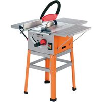
| Product type | Table circular saw |
| Brand | Einhell |
| Model | TE-TS 1825 U |
| Supply voltage | 230 V |
| Frequency | 50 Hz |
| Power consumption | 1800 W |
| No-load speed | 4500 rpm |
| Blade diameter | 250 mm |
| Max. cutting depth | 70 mm |
| Cutting angle | 0° to 45° |
| Dimensions (L x W x H) | 63 x 51 x 34 cm |
| Weight | 15 kg |
| Sliding table | Yes |
| Safety switch | Yes |
| Protective cover | Yes |
| Dust extraction connection | 36 mm |
| Parallel guide | Included |
| Warranty | 2 years |
| Maintenance and cleaning | Clean with a damp cloth, avoid solvents. Lubricate bearings with motor oil. |
| Spare parts and repairability | Spare parts available through Einhell customer service. |
Frequently Asked Questions - TE-TS 1825 U EINHELL
User questions about TE-TS 1825 U EINHELL
0 question about this device. Answer the ones you know or ask your own.
Ask a new question about this device
Download the instructions for your Saw in PDF format for free! Find your manual TE-TS 1825 U - EINHELL and take your electronic device back in hand. On this page are published all the documents necessary for the use of your device. TE-TS 1825 U by EINHELL.
USER MANUAL TE-TS 1825 U EINHELL
GB Original operating instructions Bench-type circular saw
natural_image
Hand placing a black plastic clip onto a metal bracket (no text or symbols visible)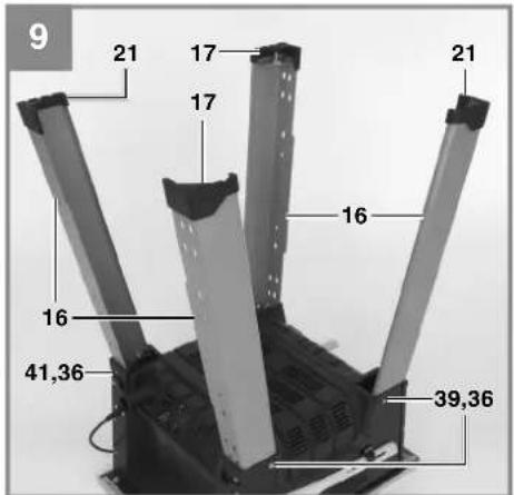

natural_image
Mechanical support frame with metal components and a labeled dimension (20), no readable text or symbols beyond the number '10' and label '11'

natural_image
Close-up of a hand adjusting a black mechanical bracket with bolts, no visible text or symbols



natural_image
Close-up of a mechanical component with gear-like teeth and a curved blade, no visible text or symbols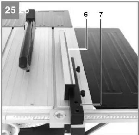


natural_image
Close-up of a hand using a cutting machine to cut wood on a workbench, no visible text or symbols
natural_image
Close-up of a hand using a tool to cut or apply material on a machine cutter board (no visible text or symbols)
natural_image
Close-up of a hand operating a workbench with a tool, no visible text or symbols
natural_image
Mechanical assembly with metal components and a flat workbench (no visible text or symbols)-7-
natural_image
Mechanical assembly on a conveyor belt with a tool and workpiece (no visible text or symbols)-8-
D
Inhaltsverzeichnis
- Safety regulations
- Layout and items supplied
- Proper use
- Technical data
- Before starting the equipment
- Assembly
- Operation
- Operation
- Replacing the power cable
- Cleaning, maintenance and ordering of spare parts
- Disposal and recycling
- Storage
GB

Caution - Read the operating instructions to reduce the risk of inquiry

Wear ear-muffs. The impact of noise can cause damage to hearing.

Wear a breathing mask. Dust which is injurious to health can be generated when working on wood and other materials. Never use the device to work on any materials containing asbestos!

Wear safety goggles. Sparks generated during working or splinters, chips and dust emitted by the device can cause loss of sight.

Important. Risk of injury! Do not reach into the running saw blade.

Lifting point
GB
⚠️ Important!
When using the equipment, a few safety precautions must be observed to avoid injuries and damage. Please read the complete operating instructions and safety regulations with due care. Keep this manual in a safe place, so that the information is available at all times. If you give the equipment to any other person, hand over these operating instructions and safety regulations as well. We cannot accept any liability for damage or accidents which arise due to a failure to follow these instructions and the safety instructions.
1. Safety regulations
The corresponding safety information can be found in the enclosed booklet.
Caution!
Read all safety regulations and instructions.
Any errors made in following the safety regulations and instructions may result in an electric shock, fire and/or serious injury.
Keep all safety regulations and instructions in a safe place for future use.
2. Layout and items supplied
2.1 Layout (Fig. 1-7)
- Saw table
- Splitter
- Cover for extractor connection
- Saw blade guard
- Saw blade
-
Stop rail (parallel stop)
-
Parallel stop
-
Width extension table (left/right)
-
Guide rail for parallel stop (right)
-
Strut for width extension table
-
Clamp lever for parallel stop
-
Scale for saw blade angle
-
Adjustment lever for cutting height
-
Setting wheel for saw blade angle
-
Setting screw
-
Leg
-
Rubber foot (type A)
-
Cross strut, bent type
-
Plate
-
Cross strut, straight type
-
Rubber foot (type B)
-
Table supports
-
Guide rail for parallel stop (left)
-
Length extension table
-
Strut for length extension table
- Connecting plate for guide rails
- Stop rail for angle stop
- Angle stop
- Push stick
- Key for changing the saw blade
- Open-ended spanner 10 mm / 13 mm
- Allen key
- Self-locking nut
- Nut
- Washer, large
- Washer, medium
- Washer, small
- Allen screw
- Hex screw (M6 x 12)
- Round-head screw (M6x 16)
- Hex screw (M6 x 20)
- Extractor connection (housing)
- Table insert
- Locking lever for saw blade angle
- On/Off switch
- Overload switch
- Scale
- Groove
- Locking grip
2.2 Items supplied
Please check that the article is complete as specified in the scope of delivery. If parts are missing, please contact our service center or the nearest branch of the DIY store where you made your purchase at the latest within 5 work days after purchasing the article and upon presentation of a valid bill of purchase. Also, refer to the warranty table in the warranty provisions at the end of the operating instructions.
- Open the packaging and take out the equipment with care.
- Remove the packaging material and any packaging and/or transportation braces (if available).
- Check to see if all items are supplied.
- Inspect the equipment and accessories for transport damage.
- If possible, please keep the packaging until the end of the guarantee period.
Important!
The equipment and packaging material are not toys. Do not let children play with plastic bags, foils or small parts. There is a danger of swallowing or suff ocating!
GB
- Splitter
- Saw blade guard
- Stop rail (parallel stop)
- Parallel stop
• Width extension table (1x left / 1x right)
• Guide rail for parallel stop (right)
• Strut for width extension table (4x) - Clamp lever for parallel stop
- Longitudinal strut (3x without setting screw, 1x with setting screw)
• Rubber foot, type A (2x)
• Rubber foot, type B (2x)
• Cross strut, bent type (2x) - Plate
• Cross strut, straight type (2x)
• Table support (2x)
• Guide rail for parallel stop (left)
• Length extension table
• Strut for length extension table (2x)
• Connecting plate for guide rails - Stop rail for angle stop
Angle stop - Push stick
• Key for changing the saw blade
• Open-ended spanner 10 mm / 13 mm
Allen key
• Self-locking nut (40x) - Nut (6x)
- Washer, large (6x)
• Washer, medium (40x) - Washer, small (6x)
• Allen screw (6x)
• Hex screw, size M6 x 12 (32x)
• Round-head screw, size M6x 16 (6x)
• Hex screw, size M6 x 20 (8x)
• Original operating instructions
• Safety information
Please note that our equipment has not been designed for use in commercial, trade or industrial applications. Our warranty will be voided if the machine is used in commercial, trade or industrial businesses or for equivalent purposes.
The equipment is to be operated only with suitable saw blades (saw blades made of HM or CV) It is prohibited to use any type of HSS saw blade and cutting-off wheel.
To use the equipment properly you must also observe the safety information, the assembly instructions and the operating instructions to be found in this manual.
All persons who use and service the equipment have to be acquainted with these operating instructions and must be informed about the equipment's potential hazards. It is also imperative to observe the accident prevention regulations in force in your area. The same applies for the general rules of health and safety at work.
The manufacturer will not be liable for any changes made to the equipment nor for any damage resulting from such changes. Even when the equipment is used as prescribed it is still impossible to eliminate certain residual risk factors.
The following hazards may arise in connection with the machine's construction and design:
- Contact with the saw blade in the uncovered saw zone.
- Reaching into the running saw blade (cut injuries).
- Kick-back of workpieces and parts of workpieces.
- Saw blade fracturing
- Catapulting of faulty carbide tips from the saw blade.
- Damage to hearing if essential ear-muffs are not used.
- Harmful emissions of wood dust when used in closed rooms.
3. Proper use
The bench-type circular saw is designed for the slitting and cross-cutting (only with the cross stop) of all types of timber commensurate with the machine's size. The equipment is not to be used for cutting any type of round wood.
The equipment is to be used only for its prescribed purpose. Any other use is deemed to be a case of misuse. The user / operator and not the manufacturer will be liable for any damage or injuries of any kind caused as a result of this.
GB
4. Technical data
Mains voltage.....230-240 V \~ 50Hz
Power P ....S1 1500 W S6 40% 1800 W
Idle speed n_0 .....6,000 min ^-1
Carbide blade .....∅ 250 x ∅ 30 x 2.4 mm
Number of teeth 24
Table size 610 x 445 mm
Table width extension, left/right .....608 x 250 mm
Table length extension, rear .....435 x 320 mm
Max. cutting height 75 mm / 90°
53 mm / 45°
Height adjustment .... infi nite 0 - 75 mm
Tilting saw blade .... infinite 0° - 45°
Extractor socket ....∅ 36 mm
Weight..... approx. 25 kg
Sound and vibration
Sound and vibration values were measured in accordance with EN 61029.
Operation
L_nA sound pressure level ..... 95,7 dB(A)
K_nA uncertainty 3 dB
L_WA sound power level 108,7 dB(A)
K_WA uncertainty ....3 dB
The quoted values are emission values and not necessarily reliable workplace values. Although there is a correlation between emission and immission levels it is impossible to draw any certain conclusions as to the need for additional precautions. Factors with a potential influence on the actual immission level at the workplace include the duration of impact, the type of room, and other sources of noise etc., e.g. the number of machines and other neighboring operations. Reliable workplace values may also vary from country to country. With this information the user should at least be able to make a better assessment of the dangers and risks involved.
Wear ear-muff s.
The impact of noise can cause damage to hearing.
Keep the noise emissions and vibrations to a minimum.
- Only use appliances which are in perfect working order.
• Service and clean the appliance regularly.
• Adapt your working style to suit the appliance.
• Do not overload the appliance.
- Have the appliance serviced whenever necessary.
• Switch the appliance off when it is not in use.
Residual risks
Even if you use this electric power tool in accordance with instructions, certain residual risks cannot be rules out. The following hazards may arise in connection with the equipment's construction and layout:
- Lung damage if no suitable protective dust mask is used.
- Damage to hearing if no suitable ear protection is used.
- Health damage caused by hand-arm vibrations if the equipment is used over a prolonged period or is not properly guided and maintained.
5. Before starting the equipment
Before you connect the equipment to the mains supply make sure that the data on the rating plate are identical to the mains data.
Always pull the power plug before making adjustments to the equipment.
- Unpack the bench-type circular saw and check it for damage which may have occurred in transit.
• Make sure the machine stands securely, i.e. bolt it to a workbench or solid base. - All covers and safety devices have to be properly fitted before the equipment is switched on.
• It must be possible for the blade to run freely. - When working with wood that has been processed before, watch out for foreign bodies such as nails or screws, etc.
- Before you actuate the On/Off switch, make sure that the saw blade is correctly fitted and that the equipment's moving parts run smoothly.
GB
6. Assembly
Important. Always screw together the connections which have self-locking nuts (see. Fig. 5, Item 33) by turning the hex screw while holding the self-locking nut firmly to fasten tightly.
6.1 Assembling the base frame (Fig. 8-13)
- Turn the saw upside down and place it on the floor.
- Use the hex screws (41), washers (36) and nuts (33) to fasten the two front legs (16) loosely to the front of the saw.
- Use the hex screws (41), washers (36) and nuts (33) to fasten the two back legs (16) loosely to the back of the saw.
- Do not yet screw any screws into the two drill holes in the middle at the back, as this is where the struts for the length extension table are to be fastened later (see 6.2.1).
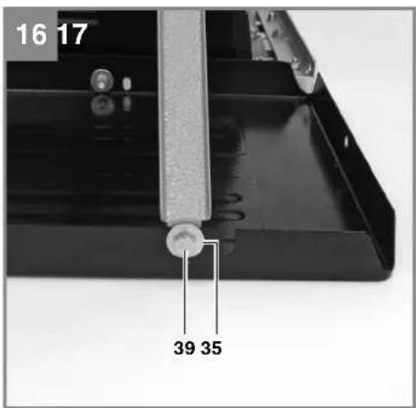
- Use the hex screws (39), washers (36) and nuts (33) to fasten all four legs to the sides of the machine.
- Do not yet screw any screws into the outer drill holes, as this is where the struts for the width extension tables are to be fastened later (see 6.2.2).
• Mount the rubber feet (17, 21) on the legs. - Screw the cross struts (20) loosely to the legs and also screw the table supports (22) to the rear legs and cross struts at the same time such that they point towards the rear of the machine and touch the ground.
- Screw the plate (19) to the bent cross struts (18), then screw the bent cross struts loosely to the legs.
6.2 Fitting the table width extension and table length extension
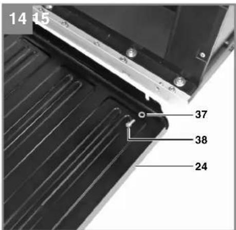
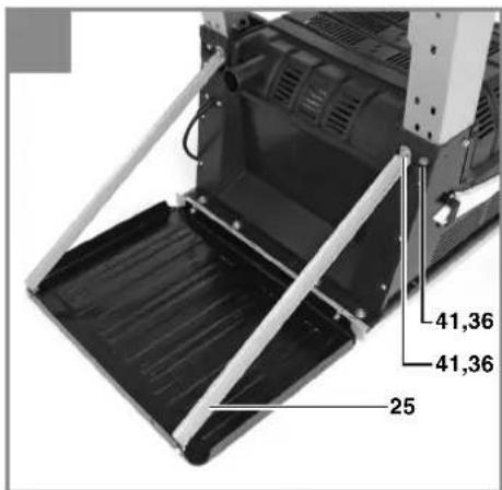
6.2.1 Length extension table (Fig. 14-16)
- Loosely fasten the length extension table (24) to the saw table using the Allen screws (38) and the washers (37).
- Screw the struts (25) loosely to the length extension table and the machine housing.
- To fasten the length extension table to the machine housing, use the hex screws (41), washers (36) and nuts (33).
- Align the table length extension with the saw table (1) so that it is flat and tighten all the nuts and screws.
6.2.2 Width extension table (Fig. 17-18)
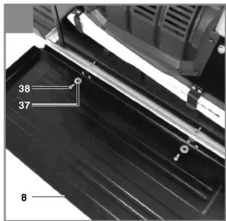
- Loosely fasten the width extension table (8) to the saw table using the Allen screws (38) and the washers (37). Use the rear holes closer to the table length extension to mount the table width extension.
- Screw the struts (10) loosely to the width extension table and the machine housing.
- To fasten the width extension table to the machine housing, use the hex screws (39), washers (36) and nuts (33).
- Align the table width extension with the saw table (1) so that it is flat and tighten all the nuts and screws.
6.2.3 Guide rails for parallel stop (Fig. 19-20)
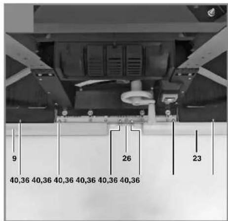
- Insert two round-head screws (40) into the groove in each of the left and right guide rail (9, 23) respectively.
- Loosely fasten the round-head screws (40) to the width extension tables (8) and the saw table (1). Use the nuts to do so (34).
- Then fasten the connecting plate (26) to the saw table (1) using two round-head screws (40) and two nuts (34).
- Slide the guide rails onto the connecting plate (26) and loosely tighten all the round-head screws.
- Once you have stood the table on its legs, you can check the position of the guide rails. The zero point on the scale on the guide rail must run into the intended cutting line of the saw blade; check with the parallel stop. Now fully tighten the round-head screws.
6.3 Fitting and setting the splitter (Fig. 21a, 21b)
• Important. Pull out the power plug.
• Take out the table insert (43) (see 6.5).
- Insert the splitter (2) in the provided holder.
- Set the blade (5) to max. cutting depth, move to 0° position and lock in place.
- Push up the splitter (2) until the gap between the saw table (1) and the upper edge of the splitter equals approx. 10 cm.
- The distance between the blade (5) and the splitter (2) should be 3-5 mm.
- Tighten the screw (z) and mount the table insert.
GB
6.4 Fitting the saw blade guard (Fig. 1, 22)
- Fit the saw blade guard (4) in the oval hole (y) in the splitter. Fasten the saw blade guard using the screw (x) and tighten the screw only enough to allow the saw blade guard to move still.
- The saw blade guard must always be lowered over the workpiece before you begin to cut.
- To connect the suction hose of an extraction system, the cover (3) on the saw blade guard can be removed (suction hose/extraction system not included).
- The machine is not allowed to be used without the saw blade guard.
6.5 Replacing the table insert (Fig. 23)
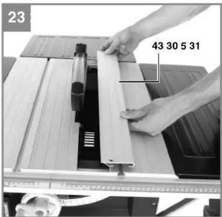
- The table insert has to be opened if you need to replace it if it gets damaged and whenever you change the blade or set the splitter.
- To prevent increased likelihood of injury, you should replace the table insert whenever it is worn or damaged.
• Important. Pull out the power plug. - Remove the saw blade guard (4).
- Remove the countersunk head screws on the table insert.
• Take out the table insert (43). - Fit the replacement table insert by following the above in reverse.
6.6 Fitting/replacing the blade (Fig. 24)
• Important. Pull out the power plug.
• Always wear gloves when handling saw blades. Risk of injury!
- Remove the table insert by undoing the two countersunk head screws (see 6.5).
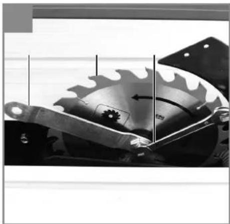
- Undo the nut with the one wrench (30) on the nut itself and an open-ended wrench (31) on the motor shaft to apply counter-pressure.
- Important. Turn the nut in the direction of rotation of the saw blade.
- Take off the outer flange and pull the old saw blade off the inner flange by dropping the blade at an angle.
- Clean the blade flange thoroughly before fitting the new blade.
- Mount and fasten the new saw blade in reverse order. Important. Note the running direction. The cutting angle of the teeth must point in running direction, i.e. forwards (see the arrow on the blade guard).
- Refit and set the splitter (2) and the saw blade guard (4) (see 6.3., 6.4.)
- Check to make sure that all safety devices are properly mounted and in good working
condition before you begin working with the saw again.
7. Operation
7.1. ON/OFF switch and overload switch (Fig. 7)
- To turn the saw on, press the green button „I“. Wait for the blade to reach its maximum speed of rotation before commencing with the cut.
- To turn the equipment off again, press the red button „0“.
The motor of this equipment is protected against overload by an overload switch (46). If the rated current is exceeded, the overload switch (46) will shut down the equipment.
- Let the equipment cool down for several minutes.
- Press the overload switch.
- Press the green button „I“ to switch on the equipment.
7.2. Cutting depth (Fig. 7)
Turn the hand crank (13) to set the blade (5) to the required cutting depth.
Turn anti-clockwise:
larger cutting depth
Turn clockwise:
smaller cutting depth
7.3. Parallel stop
7.3.1. Stop height (Fig. 25, 26)
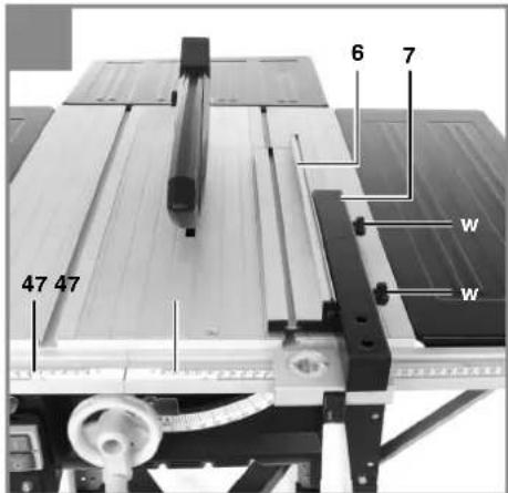
- The parallel stop (7) supplied with the bench-type circular saw has two different guide faces.
- For thick material you must use the stop rail (6) as shown in Fig. 25, for thin material you must use the stop rail as shown in Fig. 26.
- To change over the stop rail (6) you have to slacken the two knurled screws (w) in order to disconnect the stop rail (6) from the parallel stop (7).
- Depending on the required cutting height, the stop rail can be slid into two different grooves on the parallel stop and secured with the knurled screws.
- The stop rail can be taken off and fastened to either the right or left parallel stop depending
GB
on the purpose.
- The parallel stop is set at right-angles to the guide rail at the factory. It can be readjusted using two Allen screws (in the parallel stop).
7.3.2. Cutting width (Fig. 1, 25, 26)
- The parallel stop (7) has to be used when making longitudinal cuts in wooden workpieces.
- The parallel stop (7) can be mounted on either side of the saw table (1).
- The parallel stop (7) has to be mounted in the guide rail (9, 23) of the saw table (1).
- The parallel stop (7) can be set to the required dimension with the help of the scale (47) on the guide rail (1).
- You can clamp the parallel stop in the required position by pressing the lever (11).
7.3.3. Setting the stop length (Fig. 27)
- The stop rail (6) can be moved in longitudinal direction in order to prevent the workpiece from becoming jammed.
- Rule of thumb: The rear end of the stop comes up against an imaginary line that begins roughly at the center of the blade and runs at an angle of 45^ to the rear.
- Set the required cutting width
- Slacken the knurled screws (w) and push the stop rail (6) forward until it touches the imaginary 45° line.
- Retighten the knurled screws (w).
7.4. Angle stop (Fig. 28)
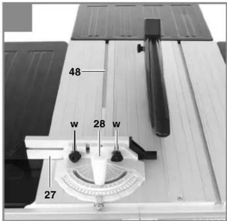
- Slide the angle stop (28) into the groove (48) of the saw table.
• Slacken the knurled screw (w). - Turn the stop rail (27) until the arrow points to the angle required.
• Retighten the knurled screw (w).
Important.
- Do not push the stop rail (27) too far toward the blade.
- The distance between the stop rail (27) and the blade (4) should be approx. 2 cm.
7.5. Setting the angle (Fig. 4, 7)
• Undo the fixing handle (44).
- Turn the wheel (15) to set the desired angle on the scale.
- Lock the fixing handle again in the required angle position.
8. Operation
Important!!
• After every new adjustment we recommend you to make a trial cut in order to check the new settings.
- After switching on the saw, wait for the blade to reach its maximum speed of rotation before commencing with the cut.
• Take extra care when starting the cut!
- Never use the equipment without the suction function.
- Regularly check and clean the suction channels.
8.1. Making longitudinal cuts (Figure 29)
Longitudinal cutting (also known as slitting) is when you use the saw to cut along the grain of the wood. Press one edge of the workpiece against the parallel stop (7) while the fl at side lies on the saw table (1). The blade guard (4) must always be lowered over the workpiece. When you make a longitudinal cut, never adopt a working position that is in line with the cutting direction.
- Set the parallel stop (7) in accordance with the workpiece height and the desired width. (See 7.3.)
- Switch on the saw.
- Place your hands (with fingers closed) flat on the workpiece and push the workpiece along the parallel stop (7) and into the blade (5).
- Guide at the side with your left or right hand (depending on the position of the parallel stop) only as far as the front edge of the guard hood.
- Always push the workpiece through to the end of the splitter (2).
- The offcut piece remains on the saw table (1) until the blade (5) is back in its position of rest.
- Secure long workpieces against falling off at the end of the cut (e.g. with a roller stand etc.)
8.1.2. Cutting narrow workpieces (Fig. 30)
Be sure to use a push stick (29) when making longitudinal cuts in workpieces smaller than 120 mm in width. A push stick is supplied with the saw! Replace a worn or damaged push stick immediately.
GB
8.1.3. Cutting very narrow workpieces (Fig. 31)
- Be sure to use a push block when making longitudinal cuts in very narrow workpieces with a width of 30 mm and less.
- The low guide face of the parallel stop is best used in this case.
- There is no push block supplied with the saw! (Available from your specialist dealer) Replace the push block without delay when it becomes worn.
8.1.4. Making angular cuts (Fig. 32)
Angular cuts must always be used using the parallel stop (7).
- Set the blade (5) to the desired angle. (See 7.5.)
- Set the parallel stop (7) in accordance with the workpiece width and height (see 7.3.1)
- Carry out the cut in accordance with the workpiece width (see 8.1.1., 8.1.2 and 8.1.3.)
8.1.5. Making cross cuts (Fig. 33)
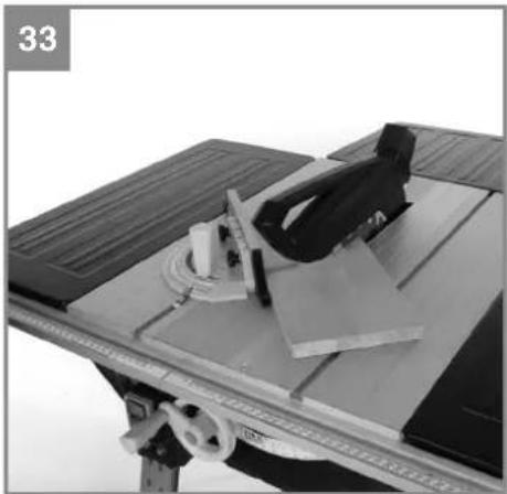
- Slide the angle stop (28) together with the stop rail (27) into one of the grooves in the saw table (1) and adjust to the required angle. (See 7.4.) If you also want to tilt the blade (5), use the groove which prevents your hand and the cross stop from making contact with the blade guard.
- If necessary, position the stop rail (27) so that it cannot collide with the saw blade when you make your cut.
- Press the workpiece firmly against the stop rail (27).
- Switch on the saw.
- Push the angle stop (28) and the workpiece toward the blade in order to make the cut.
- Important: Always hold the guided part of the workpiece. Never hold the part which is to be cut off.
- Push the angle stop (28) forward until the workpiece is cut all the way through.
- Switch off the saw again. Do not remove the offcut until the blade has stopped rotating.
9. Replacing the power cable
If the power cable for this equipment is damaged, it must be replaced by the manufacturer or its after-sales service or similarly trained personnel to avoid danger.
10. Cleaning, maintenance and ordering of spare parts
Always pull out the mains power plug before starting any cleaning work.
10.1 Cleaning
- Keep all safety devices, air vents and the motor housing free of dirt and dust as far as possible. Wipe the equipment with a clean cloth or blow it with compressed air at low pressure.
- We recommend that you clean the device immediately each time you have finished using it.
- Clean the equipment regularly with a moist cloth and some soft soap. Do not use cleaning agents or solvents; these could attack the plastic parts of the equipment. Ensure that no water can seep into the device. The ingress of water into an electric tool increases the risk of an electric shock.
10.2 Carbon brushes
In case of excessive sparking, have the carbon brushes checked only by a qualified electrician. Important! The carbon brushes should not be replaced by anyone but a qualified electrician.
10.3 Maintenance
There are no parts inside the equipment which require additional maintenance.
10.4 Transport
- Only ever transport the machine by lifting it by the saw table. Never use the safety devices such as the saw blade guard and stop rails for handling or transporting purposes.
- Suitable lifting points are marked with arrows on the saw table.
- Secure the equipment against slipping; tie it down securely.
10.5 Ordering replacement parts:
Please quote the following data when ordering replacement parts:
• Type of machine
• Article number of the machine
• Identification number of the machine
- Replacement part number of the part required For our latest prices and information please go to www.isc-gmbh.info
GB
11. Disposal and recycling
The equipment is supplied in packaging to prevent it from being damaged in transit. The raw materials in this packaging can be reused or recycled. The equipment and its accessories are made of various types of material, such as metal and plastic. Never place defective equipment in your household refuse. The equipment should be taken to a suitable collection center for proper disposal. If you do not know the whereabouts of such a collection point, you should ask in your local council offices.
12. Storage
Store the equipment and accessories out of children's reach in a dark and dry place at above freezing temperature. The ideal storage temperature is between 5 and 30^ . Store the electric tool in its original packaging.
GB

For EU countries only
Never place any electric power tools in your household refuse.
To comply with European Directive 2002/96/EC concerning old electric and electronic equipment and its implementation in national laws, old electric power tools have to be separated from other waste and disposed of in an environment-friendly fashion, e.g. by taking to a recycling depot.
Recycling alternative to the return request:
As an alternative to returning the equipment to the manufacturer, the owner of the electrical equipment must make sure that the equipment is properly disposed of if he no longer wants to keep the equipment. The old equipment can be returned to a suitable collection point that will dispose of the equipment in accordance with the national recycling and waste disposal regulations. This does not apply to any accessories or aids without electrical components supplied with the old equipment.
The reprinting or reproduction by any other means, in whole or in part, of documentation and papers accompanying products is permitted only with the express consent of the iSC GmbH.
Subject to technical changes
GB
Service information
We have competent service partners in all countries named on the guarantee certificate whose contact details can also be found on the guarantee certificate. These partners will help you with all service requests such as repairs, spare and wearing part orders or the purchase of consumables.
Please note that the following parts of this product are subject to normal or natural wear and that the following parts are therefore also required for use as consumables.
| Category Example | |
| Wear parts* V-belt, carbon brushes, table insert, push stick | |
| Consumables* Saw blade | |
| Missing parts | |
* Not necessarily included in the scope of delivery!
In the effect of defects or faults, please register the problem on the internet at www.isc-gmbh.info. Please ensure that you provide a precise description of the problem and answer the following questions in all cases:
• Did the equipment work at all or was it defective from the beginning?
• Did you notice anything (symptom or defect) prior to the failure?
• What malfunction does the equipment have in your opinion (main symptom)?
Describe this malfunction.
GB
Warranty certifi cate
Dear Customer,
All of our products undergo strict quality checks to ensure that they reach you in perfect condition. In the unlikely event that your device develops a fault, please contact our service department at the address shown on this guarantee card. You can also contact us by telephone using the service number shown. Please note the following terms under which guarantee claims can be made:
- These guarantee terms apply to consumers only, i.e. natural persons intending to use this product neither for their commercial activities nor for any other self-employed activities. These warranty terms regulate additional warranty services, which the manufacturer mentioned below promises to buyers of its new products in addition to their statutory rights of guarantee. Your statutory guarantee claims are not affected by this guarantee. Our guarantee is free of charge to you.
- The warranty services cover only defects due to material or manufacturing faults on a product which you have bought from the manufacturer mentioned below and are limited to either the rectification of said defects on the product or the replacement of the product, whichever we prefer. Please note that our devices are not designed for use in commercial, trade or professional applications. A guarantee contract will not be created if the device has been used by commercial, trade or industrial business or has been exposed to similar stresses during the guarantee period.
-
The following are not covered by our guarantee:
-
Damage to the device caused by a failure to follow the assembly instructions or due to incorrect installation, a failure to follow the operating instructions (for example connecting it to an incorrect mains voltage or current type) or a failure to follow the maintenance and safety instructions or by exposing the device to abnormal environmental conditions or by lack of care and maintenance.
- Damage to the device caused by abuse or incorrect use (for example overloading the device or the use or unapproved tools or accessories), ingress of foreign bodies into the device (such as sand, stones or dust, transport damage), the use of force or damage caused by external forces (for example by dropping it).
-
Damage to the device or parts of the device caused by normal or natural wear or tear or by normal use of the device.
-
The guarantee is valid for a period of 24 months starting from the purchase date of the device. Guarantee claims should be submitted before the end of the guarantee period within two weeks of the defect being noticed. No guarantee claims will be accepted after the end of the guarantee period. The original guarantee period remains applicable to the device even if repairs are carried out or parts are replaced. In such cases, the work performed or parts fitted will not result in an extension of the guarantee period, and no new guarantee will become active for the work performed or parts fitted. This also applies if an on-site service is used.
-
To make a claim under the guarantee, please register the defective device at: www.isc-gmbh.info. Please keep your bill of purchase or other proof of purchase for the new device. Devices that are returned without proof of purchase or without a rating plate shall not be covered by the guarantee, because appropriate identification will not be possible. If the defect is covered by our guarantee, then the item in question will either be repaired immediately and returned to you or we will send you a new replacement.
Of course, we are also happy offer a chargeable repair service for any defects which are not covered by the scope of this guarantee or for units which are no longer covered. To take advantage of this service, please send the device to our service address.
Also refer to the restrictions of this warranty concerning wear parts, consumables and missing parts as set out in the service information in these operating instructions.
F
Sommaire
Negotovost K_pA .....3 dB
Nivo zvočne moči L _WA 108,7 dB (A)
Negotovost K_WA 3 dB
Subject to change without notice
Archive-File/Record: NAPR003649
Documents registrar: Siegfried Roider
Wiesenweg 22, D-94405 Landau/Isar
EH 11/2015 (02)

- Inhaltsverzeichnis
- GB
- ⚠️ Important!
- Safety regulations
- Caution!
- Layout and items supplied
- Layout (Fig. 1-7)
- Items supplied
- Important!
- Proper use
- Technical data
- Sound and vibration
- Operation
- Wear ear-muff s.
- Keep the noise emissions and vibrations to a minimum.
- Residual risks
- Even if you use this electric power tool in accordance with instructions, certain residual risks cannot be rules out. The following hazards may arise in connection with the equipment's construction and layout:
- Before starting the equipment
- Always pull the power plug before making adjustments to the equipment.
- Assembly
- Assembling the base frame (Fig. 8-13)
- Fitting the table width extension and table length extension
- Length extension table (Fig. 14-16)
- Width extension table (Fig. 17-18)
- Guide rails for parallel stop (Fig. 19-20)
- Fitting and setting the splitter (Fig. 21a, 21b)
- Fitting the saw blade guard (Fig. 1, 22)
- Replacing the table insert (Fig. 23)
- Fitting/replacing the blade (Fig. 24)
- Operation
- ON/OFF switch and overload switch (Fig. 7)
- Cutting depth (Fig. 7)
- Turn anti-clockwise:
- Turn clockwise:
- Parallel stop
- Stop height (Fig. 25, 26)
- Cutting width (Fig. 1, 25, 26)
- Setting the stop length (Fig. 27)
- Angle stop (Fig. 28)
- Important.
- Setting the angle (Fig. 4, 7)
- Operation
- Important!!
- Making longitudinal cuts (Figure 29)
- Cutting narrow workpieces (Fig. 30)
- Cutting very narrow workpieces (Fig. 31)
- Making angular cuts (Fig. 32)
- Making cross cuts (Fig. 33)
- Replacing the power cable
- Cleaning, maintenance and ordering of spare parts
- Cleaning
- Carbon brushes
- Maintenance
- Transport
- Ordering replacement parts:
- Disposal and recycling
- Storage
- Service information
- Warranty certifi cate
- F
- Sommaire
Brand : EINHELL
Model : TE-TS 1825 U
Category : Saw