
VOS 40/F - TV amplifier KATHREIN - Free user manual and instructions
Find the device manual for free VOS 40/F KATHREIN in PDF.


| Product type | TV amplifier |
| Brand | Kathrein |
| Model | VOS 40/F |
| Dimensions (W x D x H) | Approx. 85 x 55 x 25 mm |
| Weight | Approx. 90 g |
| Power supply | 5 V / 100 mA mains adapter (not included) |
| Power consumption | < 0.5 W |
| Frequency range | VHF (174-230 MHz) / UHF (470-862 MHz) |
| Gain | Approx. 15 dB (adjustable) |
| Noise figure | < 4 dB |
| Impedance | 75 Ω (balanced) |
| Input/output connectors | 2 × F (female) |
| Number of outputs | 1 (with possible remote power feeding) |
| Main functions | DTT signal amplification, cable loss compensation, reception improvement |
| Care and cleaning | Clean with a soft, dry cloth. Do not use liquids or abrasive products. |
| Safety | Do not open the housing. Disconnect before cleaning. Only use the recommended adapter. |
| Spare parts and repairability | No user-serviceable parts. Contact a qualified technician or Kathrein customer service. |
| General information | Compact amplifier for indoor installation. Suitable for digital DVB-T/T2 signals. |
Frequently Asked Questions - VOS 40/F KATHREIN
User questions about VOS 40/F KATHREIN
0 question about this device. Answer the ones you know or ask your own.
Ask a new question about this device
Download the instructions for your TV amplifier in PDF format for free! Find your manual VOS 40/F - KATHREIN and take your electronic device back in hand. On this page are published all the documents necessary for the use of your device. VOS 40/F by KATHREIN.
USER MANUAL VOS 40/F KATHREIN
Rückweg-Verstärker
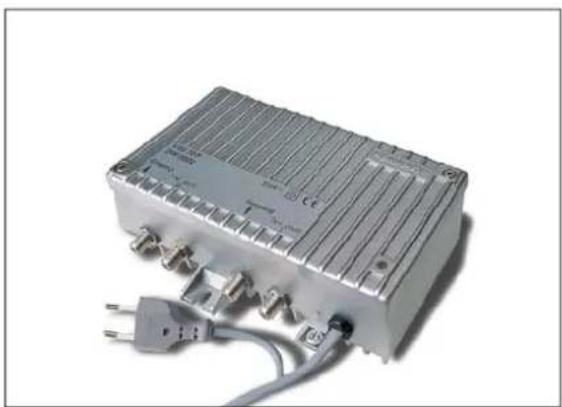
• House connection amplifiers for modern HFC networks
• Integrated power supply unit
• Die-cast housing with F connectors
• LED to indicate operation mode
- Gain with interstage attenuation is switchable using jumpers (delivery condition: high gain)
- VOS 40/F: Interstage equaliser (6 dB) can be connected using jumpers (Pre-emphasis)
- Return path optional, can be configured as required:
5-30 MHz with VGR 28/30
5-65 MHz with VGR 28/65
(delivery condition: without return path amplifier, with jumpers)
- Integrated, variable attenuator and variable equaliser
- Test socket on output -20 dB (with directional coupler)
- Complies with: EN 60728-11, EN 50083-2 and EN 60065
- For indoor installation
- Test socket on input -20 dB (can be connected using jumpers) for return path levelling
- The amplifiers comply with the requirements in the Low-Voltage Directive 2006/95/EEC and EMC Directive 2004/108/EEC applicable at the time of shipping.
| Type | VOS 30/F | VOS 40/F | |
| Order no. | 20910002 | 20910012 | |
| Forward path | |||
| Frequency range | MHz 47 (85)-862 | ||
| Gain (switchable) | dB 24/30 34/40 | ||
| Amplitude ripple | dB +/- 1.5 | ||
| Adjustable attenuator setting range | dB 0-20 | ||
| Equaliser setting range | dB 0-20 | ||
| Interstage adjustable attenuator setting range (can be switched with jumpers) | dB 0/6 | ||
| Interstage equaliser setting range (can be switched with jumpers) | dB - 0/6 | ||
| Maximum operating level 11 (60-dB CTB/CSO) - 1 at - with 6-dB interstage pre-emphasis | dBμV | 98/100 | 104/107106/107 |
| Noise figure | dB 7/6 | ||
| Number of outputs | 1 | ||
| Return path | |||
| For data see VGR 28/xx | |||
| General | |||
| Impedance input/output | Ω 75 | ||
| Return loss input/output 21 | dB 14 | ||
| RF connections | F connector | ||
| Test socket output with directional coupler (5-862 MHz) | dB -20 | ||
| Test socket output return path (5-65 MHz) | dB -20 | ||
| Supply voltage | VAC | 198-253 | |
| Power consumption (without/with return path amplifier) | W | 7/9 | 6/7 |
| Indication of operation mode | LED green | ||
| Protection class | II | ||
| Protection class (in accordance with EN 60529) | IP 50 | ||
| Temperature range | °C | -20 to +55 | |
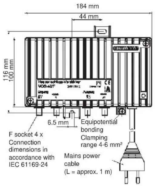
| Dimensions | mm | 184 x 134 x 63 | |
| Packing unit/weight | pc./kg | 1 (10)/1.6 | 1 (10)/1.4 |
In accordance with EN 60728-3; CENELEC channel plan 42 carriers
2) In accordance with EN 60728-3 (category C); from 40 MHz 14 dB-1.5 dB/octave, but 10 dB
Return path amplifier
- Please order separately
- Variable equaliser and variable attenuator (delivery condition: max. attenuation) on the output

| Type VGR 28/30 VGR 28/65 | |||
| Order no. 20910008 20910009 | |||
| Frequency range 5-30 5-65 | |||
| Gain dB 28 | |||
| Max. output level 60-dB-IMA3 dBμV 118 | |||
| 60-dB-IMA2 dBμV 112 | |||
| Input level density (CINR: 55 dB) dBμV/Hz Type -6 | |||
| Dynamic range (input level density) | dB | Type 19 | |
| Noise figure | dB | 5 | |
| Gain setting (on the output) 1) | dB | 0-20 | |
| Equalisation setting (on the output) | dB | 0-20 | |
| Dimensions (W x H x D) | mm | 130 x 17 x 38 | |
| Packing unit/weight | pc./kg | 1 (10)/0.08 | |
1) In the delivery status the adjustable attenuator is set to max. attenuation.
Note: The purpose of this graphic is to explain the terms "input level density" and "dynamic range". It is not possible to derive any electrical data from the graphic. See also: EN 60728-3 (point 4.7)

Block diagram: VOS 40/F
![graph TD A["Input 5-862 MHz"] --> B["0-20dB"] B --> C["0-20dB"] C --> D["0 or 6 dB"] D --> E["0 or 6dB"] E --> F["47-862MHz 85-862 MHz"] F --> G["Option VGR 28/30 VGR 28/65"] G --> H["5-30MHz 5-65MHz"] H --> I["0-20 dB"] I --> J["0-20 dB"] J --> K["5-30MHz 5-65MHz"] K --> L["Output 5-862 MHz"] L -->…](/content/2026/06/1264801/images/1598a6feab1eab1ef14cb273253dbe238a5cc338f7ad75ad9533b3700b4f42ca.jpg)
Installation: Only by authorised persons
Unplug from the mains before installation. The safety regulations in accordance with EN 60728-11 and EN 60065 must be observed!
Permissible installation
Caution! Do not mount on easily inf1 ammable materials!


a) Clearances to containing surfaces: ≥ 150 mm b) Clearances to containing surfaces: ≥ 50 mm
Basic safety precautions

Caution!
The amplifier supply voltage is 230 V AC and is dangerous on direct contact!
- Do not touch live parts
- The power plug must be easily operable as the means of cutting power to the amplifier, meaning the wall outlet must be close to the amplifier and easily accessible
- The power must be cut when installing or removing the amplifier
- The amplifier must not be operated without the standard power supply protective cover fitted. The cover must be closed
Controls and plug-in modules


Electronic equipment is not domestic waste - in accordance with directive 2002/96/EC OF THE EUROPEAN PARLIAMENT AND THE COUNCIL dated 27 th January 2003 on used electrical and electronic appliances, it must be disposed of properly.
At the end of its service life, take this unit for disposal to an appropriate official collection point.

Brand : KATHREIN
Model : VOS 40/F
Category : TV amplifier