
VWS 2500 - TV amplifier KATHREIN - Free user manual and instructions
Find the device manual for free VWS 2500 KATHREIN in PDF.


| Product Type | TV Amplifier |
| Brand | Kathrein |
| Model | VWS 2500 |
| Dimensions (approx.) | 120 x 80 x 40 mm |
| Weight (approx.) | 200 g |
| Power Supply | 12 V DC, 500 mA |
| Power Consumption | < 6 W |
| Frequency Range | 47 - 862 MHz |
| Gain | 20 dB typical |
| Input Connector | F-type female |
| Output Connector | F-type female |
| Number of Outputs | 1 |
| Noise Figure | < 3 dB | Operating Temperature | -10°C to +50°C |
| Cleaning Instructions | Wipe with dry cloth; do not use liquids |
| Safety | Use only supplied power adapter; keep away from moisture |
| Spare Parts / Repairability | Contact Kathrein service for spare parts |
Frequently Asked Questions - VWS 2500 KATHREIN
User questions about VWS 2500 KATHREIN
0 question about this device. Answer the ones you know or ask your own.
Ask a new question about this device
Download the instructions for your TV amplifier in PDF format for free! Find your manual VWS 2500 - KATHREIN and take your electronic device back in hand. On this page are published all the documents necessary for the use of your device. VWS 2500 by KATHREIN.
USER MANUAL VWS 2500 KATHREIN
Technische Daten


Kathrein-Power-Saving
Sat-IF distribution system Multi-switch distribution network amplifi er

Features
■ High dynamic range of amplifier units
■ High decoupling between the amplifi er units
■ Because it uses a GaAs final stage, the terrestrial amplifier is suitable for CATV applications
■ Adjustable attenuators (in 1-dB steps) for the satellite range and terrestrial range (the amplifi er branches for the satellite range and terrestrial range are adjusted separately)
■ Adjustable pre-emphasis (steps of 2/4/6 dB) in the satellite range (each satellite branch is adjusted separately) permits optimum pre-emphasis slope in the cascade.
- Kathrein Power Saving
In systems with devices that support Kathrein Power Saving, the LNB power supply is switched off as soon as there is no longer any receiver in operation (switch setting KPS ON)
If devices that do not support Kathrein Power Saving are included in a system, the KPS function should be deactivated (switch setting KPS OFF; Fig. A)
■ The vertical-low amplifier unit is provided with a DC bypass, so that the signal for Kathrein Power Saving can be looped through
■ Due to the additional use of a highly efficient DC/DC converter for the supply to the amplifier units, the power consumption of the amplifier is extremely low
■ An additional power-saving facility is available by selectively switching off the terrestrial amplifier when it is not required (independently of the KPS function): set the terrestrial adjustable attenuator to OFF (Fig. B)
■ Suitable for use in Kathrein sat-IF distribution systems with 4 x sat-IF (one satellite position)
A single casing incorporates 4 x amplifi ers for the satellite range and one amplifi er for the terrestrial range
■ The power supply to the amplifier units and the LNBs is provided by an integrated highly efficient switched-mode power supply.
■ For indoor mounting


Technical data
| Type | VWS 2500 | ||
| Order no. | 20510098 | ||
| Inputs | 1 x terrestrial 4 x sat-IF | ||
| Frequency range | MHz 47 - 862 950 - 2150 | ||
| Gain1) | dB 17 - 21 22 - 24 | ||
| Adjustment range of the adjustable attenuator (1 dB steps) | dB 0 - 14 0 - 15 | ||
| Equalisation setting range | dB - 2/4/6 | ||
| Max. output level (interferences 3rd order) | dBμV 113 | 2) | 1153) |
| Max. output level (interferences 2nd order) | dBμV 104 | 4) | 1103) |
| Max. operating level for CATV (up to 862 MHz)5) | dBμV 98 | - | |
| Trunk decoupling | dB 40 | ||
| Input supply voltage range | V 207 - 253 (50 - 60 Hz) | ||
| Secondary voltage (input horiz. low) | V | 18 | |
| Available remote feed current (input horiz. low) | mA | 600 | |
| Protection class/protection type | II (double insulated)/IP30 | ||
| Permissible ambient temperature | °C | -20 - +50 | |
| Dimensions (W x H x D) | mm | 255 x 148 x 43 | |
| Packing unit/weight | Units/kg 1 | (10)/0,75 | |
1) Frequency-dependent gain (pre-emphasis)
2) 60-dB-KMA to EN 50083-5
3) 35-dB-IMA to EN 60728-3
4) 60-dB-IMA to EN 60728-3
5) to EN 60728-3, 60-dB-CTB/CSO, CENELEC raster
Safety instructions
Power supply for the amplifier
The amplifier incorporates a switched-mode power supply. Via the H low port, this power supply unit also supplies the power supply system.

Warning! Risk of fatal electric shock
▶ Do not open or tamper with the unit!
▶ When working on the system always unplug the mains plug from the wall socket!
▶ Ensure adequate clearance! Clearance all round at least 5 cm!
The units must not be mounted on the ceiling.
▶ Free circulation of air must be possible to discharge the heat emitted by the unit. Risk of overheating!
Caution:
▶ Operate the device in the permissible ambient temperature range of -20 to +50 °C only.
▶ No liquid-filled items may be placed on top of the power supply unit.
The power supply unit must not be exposed to dripping or splashing water.
The mains plug must be easily accessible and operable.
The only reliable method of disconnecting the units from the mains is to unplug them.
Installation instructions

The device described is intended solely for the installation in satellite receiver systems and may only be installed by trained specialist personnel.
▶ Any other use, or failure to comply with these instructions, will result in voiding of warranty cover.
The equipment may only be installed in dry indoor areas. Do not install on or against highly combustible materials.
The equipment must be provided with an earthing wire (Cu, at least 4 mm2).
The safety regulations set out in the current EN 60728-11 and EN 62368-1 standards must be complied with.
▶ Fasteners for concrete substrates and masonry: 4 suitable plugs and associated screws with half-round or cylindrical head, outer thread diameter 4.5 - 5 mm, head diameter ≥ 9 mm and a screw length ≥ 30 mm For other types of wall, use the appropriate screws or screw-dowel systems, which offer the same or better fastening
Connector: RF plug 75 Ω (series F) to EN 61169-24.
▶ Unused subscriber ports should be closed off with 75 Ω resistors (e.g. EMK 03).
Risk of damage to property!
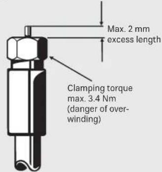
An inner cable conductor with a diameter greater than 1.2 mm, or the presence of burrs may damage the device inputs/outputs beyond repair.

General information on installation
Use of the amplifier within a satellite reception system
The VWS 2500 amplifier is used at the input to large multi-switch cascades or as a cascadable distribution network amplifier for balancing the through losses of cables, branches or distributors in large distribution networks. It must be ensured that the level at the input lies between 50 and max. 80 dBμV, and the downstream multi-switches are not overloaded.
Setting the level for the amplifier
It is best to use an antenna meter such as an MSK 130 to determine the level. You can adjust the gain in 1 dB steps (see illustration on the right). Each amplifier has its own adjustable attenuator available.
To compensate the slope of the attenuation, e.g. for long cable lengths, each sat amplifi er can be set to 2, 4 or 6 dB pre-emphasis (see the illustration on the far right). The terrestrial amplifi er is set to a fixed pre-emphasis value.
Connecting the amplifier to other devices within the sat reception system
The quickest and easiest connection, for instance to a through multi-switch, is achieved using the optional EMU 250 plug connector (illustration on the right). Here the devices are plugged into each other directly..


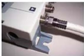
If the devices are further apart from each other, the use of high-quality coaxial cables (with very high screening values) such as LCD 111 is recommended. Where possible, use high-quality F-type connectors as crimped connectors (illustration on the right) or as compression connectors (see the Kathrein catalogue Satellite and terrestrial reception antenna systems). When using coaxial cables, take particular care to ensure correct assignment of the inputs and outputs to each other. The V low output from the amplifier must be connected to the V low input of the multi-switch, etc.
Kathrein-Power-Saving
In systems with active Kathrein Power Saving the power supply system is switched off when the last connected receiver is switched off. The terrestrial amplifier branch remains switched on so that terrestrial reception is still available. If the system does not cater for terrestrial reception and hence the terrestrial amplifier branch is not used, this can be switched off (set the terrestrial adjustable attenuator to the OFF position).
Potential equalisation
For potential equalisation, use an earthing wire of at least 4 sq. mm cross-section For earthing the device, use the earthing screw provided on the device. Every device in the reception system must be earthed.

System examples (symbolic representation)
![graph TD A["UAS 584"] --> B["KAZ 11/12"] B --> C["VWS 2500"] C --> D["EBX 2520"] D --> E["VWS 2551"] E --> F["ESD..ESC.."] F --> G["3x EXR 2558 | EXR 2508"] G --> H["ESD..ESC.."] H --> I["3x EXR 2558 | EXR 2508"] I --> J["ESD..ESC.."] J --> K["3x EXR 2558 | EXR 2508"] K --> L["ESD..ESC.."] L --> M["…](/content/2026/06/1264496/images/2dbfb5518f1c7e78753814720f4263ccab65f01a3b63d9e19c8791a9d4874135.jpg)
SIMPLIFIED EU DECLARATION OF CONFORMITY
Hereby, KATHREIN Digital Systems GmbH declares that the radio equipment type
VWS 2500, order no.: 20510098
is in compliance with Directive 2014/53/EU. The full text of the EU declaration of conformity is available at the
following internet address: www.kathrein-ds.com
Disposal

Electronic equipment
Electronic equipment is not domestic waste – in accordance with directive 2012/19/EU OF THE EUROPEAN PARLIAMENT AND THE COUNCIL dated 4th July 2012 concerning used electrical and electronic appliances, it must be disposed of properly. At the end of its service life, take this unit for disposal at a designated public collection point.

- Kathrein-power-saving
- Sat-if distribution system multi-switch distribution network amplifi er
- Features
- Safety instructions
- Power supply for the amplifier
- Warning! risk of fatal electric shock
- Caution
- Installation instructions
- Risk of damage to property
- General information on installation
- Use of the amplifier within a satellite reception system
- Setting the level for the amplifier
- Connecting the amplifier to other devices within the sat reception system
- Potential equalisation
- Simplified eu declaration of conformity
- Disposal
- Electronic equipment
Brand : KATHREIN
Model : VWS 2500
Category : TV amplifier