
VWS 2551 - TV signal amplifier KATHREIN - Free user manual and instructions
Find the device manual for free VWS 2551 KATHREIN in PDF.


| Product type | TV signal amplifier |
| Brand | Kathrein |
| Model | VWS 2551 |
| Frequency range | 47-862 MHz |
| Gain | Approx. 20 dB |
| Noise figure | ≤ 4 dB |
| Number of outputs | 1 |
| Input voltage | 12 V DC |
| Power consumption | ≤ 2 W |
| Dimensions (W x H x D) | 130 x 80 x 40 mm |
| Weight | 300 g |
| Connector type | F connector (IEC 61169-24) |
| Operating temperature | -20 °C to +55 °C |
| Protection class | IP20 (indoor use) |
| Included accessories | Power adapter, mounting bracket |
| Maintenance | Wipe with a dry cloth; do not use liquids |
| Safety | For indoor use only; disconnect power before cleaning |
| Spare parts | Power adapter available separately |
| Repairability | Not user-serviceable; contact qualified technician |
| General information | Amplifies weak TV signals for better reception |
Frequently Asked Questions - VWS 2551 KATHREIN
User questions about VWS 2551 KATHREIN
0 question about this device. Answer the ones you know or ask your own.
Ask a new question about this device
Download the instructions for your TV signal amplifier in PDF format for free! Find your manual VWS 2551 - KATHREIN and take your electronic device back in hand. On this page are published all the documents necessary for the use of your device. VWS 2551 by KATHREIN.
USER MANUAL VWS 2551 KATHREIN

Connection example![graph TD A["UAS 584"] --> B["KAZ 11/12"] B --> C["VWS 2500"] C --> D["EBX 2520"] D --> E["VWS 2551"] E --> F["3x EXR 2558 | EXR 2508"] F --> G["ESC.."] style A fill:#f9f,stroke:#333 style G fill:#ccf,stroke:#333](/content/2026/06/1264776/images/149312715898bbed8885760b6e99b6e0e4227e7b0ccb0f1aec2d8cdecb4c8ef0.jpg)
Sat-IF distribution system Multi-switch distribution network amplifier
About this guide
This document is part of the product.
▶ Do not install or use the device until you have read and understood this document. ▶ Keep this document for reference throughout the service life of the device. Pass this document on to any new owner or user.
For the most up-to-date version of this document, go to www.kathrein-ds.com.
Features
■ High dynamic range of amplifier units ■ High decoupling between the amplifier units ■ Because it uses a GaAs final stage, the terrestrial amplifier is suitable for CATV applications ■ Adjustable attenuator (in 1-dB steps) for the satellite and terrestrial range (all satellite branches are adjusted at the same time)
■ Adjustable pre-emphasis (steps of 2/4/6 dB) in the satellite range (all satellite branches are adjusted at the same time) permits optimum pre-emphasis in the cascade
■ The power supply to the VWS is provided by remote feed from the last multi-switch in the cascade via the "horizontal low" satellite branch
■ Kathrein Power-Saving:
In systems with devices that support Kathrein Power-Saving, the LNB power supply is switched off as soon as there is no longer any receiver in operation. Where remote feed is in operation, the amplifier is also switched off
■ A local power supply via the DC port using the NCF 18 power supply unit can be chosen as an option (but this does not provide the power to the LNB) ■ Suitable for use in the Kathrein Sat-ZF distribution system 4 x Sat-ZF (one satellite position)


■ Because it uses a highly efficient DC/DC converter, the power consumption of the VWS 2551 is extremely low ■ An additional power-saving option is selectively switching off the terrestrial amplifier when it is not required ■ All satellite amplifier units are fitted with a DC loop-through. This allows the supply voltage from the last multi-switch for the LNB and the flag calling for Kathrein Power-Saving to be looped through ■ For indoor installation
Technical Data
| Type VWS 2551 | ||||
| Order No. 20510099 | ||||
| Inputs 1 x terrestrial 4 x Sat-IF | ||||
| Frequency range MHz 47-862 950-2150 | ||||
| Gain 1) | dB 16 15 | |||
| Adjustable attenuator setting range (1-dB steps) dB 0-14 0-15 | ||||
| Equalisation setting range dB - 2/4/6 | ||||
| Max. output level (interferences 3rd order) | dBμV | 108 2) | 112 3) | |
| Max. output level (interferences 2nd order) | dBμV | 104 4) | 104 3) | |
| Max. operating level for CATV (up to 862 MHz) 5) | dBμV 96 | - | ||
| Decoupling trunk | dB - | 45 | ||
| Supply voltage | V | +18 | ||
| Current drain | Terr. on | mA | 85 | |
| Terr. off | 50 | |||
| Max. remote feed current (each Sat signal polarity) | mA | 1000 | ||
| Permissible ambient temperature | °C | -20 to +55 | ||
| Connections | F-type connectors | |||
| Dimensions (W x H x D) | mm | 112 x 148 x 44 | ||
| Packing unit/Weight | pc/kg | 1 (10)/0,37 | ||
1) Frequency-dependent gain (pre-emphasis) depending on the pre-equalisation setting. 60-dB XMod to EN 50083-5. 35-dB IMod to EN 60728-3. 4) 60-dB IMod to EN 60728-3. 5) To EN 60728-3, 60-dB CTB/CSO, CENELEC channel plan.
Installation and safety instructions

- The equipment described is designed solely for the installation of satellite reception systems and may only be installed by trained specialist personnel.
- Any other use, or failure to comply with these instructions, will result in voiding of warranty cover.
- The units may only be installed in dry indoor areas. Do not mount on or against highly combustible materials.
- The units should be provided with an equipotential bonding wire (Cu, at least 4 mm²).
- The safety regulations set out in the current EN 60728-11 and EN 62368-1 standards must be complied with.
- Fasteners for concrete substrates and masonry: 4 suitable plugs and associated screws with half-round or cylindrical head, outer thread diameter 4.5 - 5 mm, head diameter ≥ 9 mm and a screw length ≥ 30 mm. For other types of wall, use the appropriate screws or screw-dowel systems, which offer the same or better fastening.
- Connector: HF plug 75 Ω (series F) to EN 61169-24.
General information on installation
Installation of an amplifier in a satellite reception system
In principle, the amplifier can be built into any position in the Sat reception system (see section "System examples").
The following is to be observed:
- the level on the input should fall within the range between 50 to max. 80 dBμV and
- the multi-switches following are not to be overdriven
Levelling the amplifier
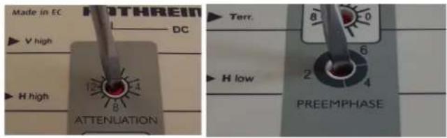
In order to define the level, it is recommended to use an antenna measuring instrument, e.g. MSK 200. You can adjust the gain in 1-dB increments (see picture on right).
The attenuator affects all Sat-range amplifier units at the same time.
To equalise attenuation slopes, such as in long cable lengths, the amplifier's pre-equalisation can be set to 2, 4 and 6 dB. The terrestrial amplifier is adjusted with its own attenuator.
Connection of the amplifier to other units of the Sat reception system
The easiest and quickest way to connect the amplifier to, e.g. a loop-through multi-switch is by using the optional connector EMU 250 (see picture on right). This enables the units to be connected to each other directly.
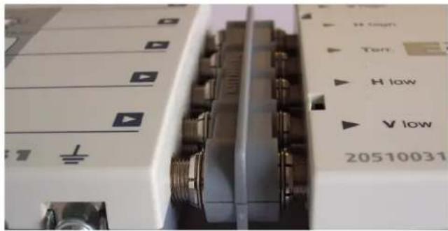
If the units are far apart, it is recommended to use high-quality coaxial cables (with very high screening values), e.g. LCD 111. If possible, use high-quality F-type connectors (see picture right) for “crimping” or compression connectors (see Kathrein catalogue “Satellite and terrestrial antenna products and systems”).


When using coaxial cables, it is especially important to make sure that the inputs and outputs are correctly assigned to one another.
The amplifier's "V low" output must be connected to the multiswitch's "V low" input, etc.

If the inner cable conductor diameter is greater than 1.2 mm or in case of burr, the device sockets may be destroyed.


If the required level ratios are observed, a maximum number of three amplifiers can be operated in a cascade.
Amplifier voltage supply
Kathrein amplifiers are equipped with an innovative powering concept. The amplifiers can be powered in two ways:
- Through remote feeding via the coaxial cable of the "H low" connection on a terminal multi-switch
- Through connection of the optional NCF 18 power supply unit to the "DC" socket (does not include powering of the feed system!)
Kathrein Power-Saving
In systems where Kathrein Power-Saving is active, when the last receiver is switched off the amplifier is also switched off. If the amplifier should remain available for terrestrial reception, the amplifier should be powered via the NCF 18. In systems not fitted with Kathrein Power-Saving or terrestrial systems, the last multi-switch can provide the power.
Potential equalisation
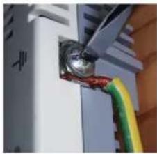
For potential equalisation use an earthing wire with a cross section of at least 4 mm. The unit is to be earthed using the earthing screw provided on the unit. Each unit in the reception system must be earthed.
Connection example![graph TD A["UAS 584"] --> B["KAZ 11/12"] B --> C["VWS 2500"] C --> D["EBX 2520"] D --> E["VWS 2551"] E --> F["3x EXR 2558 | EXR 2508"] F --> G["ESC.."] G --> H["ESD.. ESC.."] H --> I["ESD.. ESC.."] I --> J["ESD.. ESC.."] J --> K["ESD.. ESC.."] K --> L["ESD.. ESC.."] L --> M["ESD.. ESC.."] M --> N["E…](/content/2026/06/1264776/images/93ec5f6381a1f0cc2a117ea20ae428a1b70ff47873d14e185c8f2d1635507230.jpg)
SIMPLIFIED EU DECLARATION OF CONFORMITY
Hereby, KATHREIN Digital Systems GmbH declares that the radio equipment type
VWS 2551, order no.: 20510099
is in compliance with Directive 2014/53/EU. The full text of the EU declaration of conformity is available at the
following internet address: www.kathrein-ds.com

Electronic equipment
Electronic equipment is not domestic waste – in accordance with directive 2012/19/EU OF THE EUROPEAN PARLIAMENT AND THE COUNCIL dated 4th July 2012 concerning used electrical and electronic appliances, it must be disposed of properly. At the end of its service life, take this unit for disposal at a designated public collection point.


- SAT-IF DISTRIBUTION SYSTEM MULTI-SWITCH DISTRIBUTION NETWORK AMPLIFIER
- ABOUT THIS GUIDE
- FEATURES
- KATHREIN POWER-SAVING
- INSTALLATION AND SAFETY INSTRUCTIONS
- GENERAL INFORMATION ON INSTALLATION
- INSTALLATION OF AN AMPLIFIER IN A SATELLITE RECEPTION SYSTEM
- LEVELLING THE AMPLIFIER
- CONNECTION OF THE AMPLIFIER TO OTHER UNITS OF THE SAT RECEPTION SYSTEM
- AMPLIFIER VOLTAGE SUPPLY
- POTENTIAL EQUALISATION
- SIMPLIFIED EU DECLARATION OF CONFORMITY
- ELECTRONIC EQUIPMENT
Brand : KATHREIN
Model : VWS 2551
Category : TV signal amplifier