
VOS 20/RA-1G - TV signal amplifier KATHREIN - Free user manual and instructions
Find the device manual for free VOS 20/RA-1G KATHREIN in PDF.


| Product Type | TV Signal Amplifier |
| Brand | Kathrein |
| Model | VOS 20/RA-1G |
| Dimensions (approx.) | 150 x 80 x 40 mm |
| Weight | 200 g |
| Power Supply | 12 V DC via included mains adapter |
| Input Frequency Range | 47 - 862 MHz |
| Gain | 20 dB (adjustable) |
| Number of Inputs | 1 RF input |
| Number of Outputs | 1 RF output |
| Main Functions | Amplify DVB-T/T2 and analog TV signals; adjustable gain; low noise figure |
| Maintenance | Wipe with dry cloth; do not use solvents |
| Safety | Operate in dry indoor environment; disconnect power during cleaning |
| Spare Parts & Repairability | No user-serviceable parts; contact service center for repair |
| General Information | Designed for indoor use; includes mounting bracket; LED power indicator |
Frequently Asked Questions - VOS 20/RA-1G KATHREIN
User questions about VOS 20/RA-1G KATHREIN
0 question about this device. Answer the ones you know or ask your own.
Ask a new question about this device
Download the instructions for your TV signal amplifier in PDF format for free! Find your manual VOS 20/RA-1G - KATHREIN and take your electronic device back in hand. On this page are published all the documents necessary for the use of your device. VOS 20/RA-1G by KATHREIN.
USER MANUAL VOS 20/RA-1G KATHREIN
House connection amplifiers
Features
■ House connection amplifiers for modern HFC networks up to 1 GHz
■ Integrated high-efficiency switched-mode power supply unit
■ Unit including forward path amplifier, return path amplifier, diplexer, actuators and power supply unit
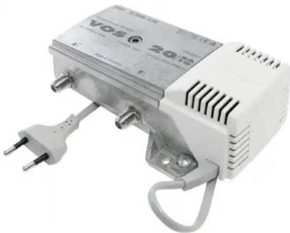
■ Die-cast housing with F-type connectors
■ LED to indicate operational mode
■ Interstage equaliser switchable with bridging plugs (6 dB pre-emphasis)
■ Integrated variable attenuator (forward and return path; delivery condition return path: max. attenuation)
■ Integrated adjustable equaliser (forward path)
■ Integrated return path 5-65 MHz active
■ Conform to: EN 60728-11, EN 50083-2 and EN 60065
■ For indoor installation
The amplifiers comply with the EMC directive 2004/108/EC and Low-Voltage Directive 2006/95/EC applicable at the time of shipping.
Basic safety precautions

■ Installation must be carried out by authorised specialist staff.
■ Unplug from the mains before installation.
■ Described amplifiers are exclusively for installation of HFC networks up to 1,006 MHz.
■ Any other use or failure to comply with these instructions will void the warranty or guarantee.
- The amplifiers may only be installed in dry areas indoors. Do not install on or against highly combustible materials.
■ The amplifiers must be earthed when installed (Cu, minimally 4 mm 2 ).
■ The safety regulations set out in the current EN 60728-11 and EN 60065 standards must be complied with.

■ The supply voltage of the amplifiers is 230 VAC which can be fatal if touched directly.
■ The only reliable method of disconnecting the amplifiers from the mains is to unplug them.
■ Do not touch live parts.
- The power plug must be easy to operate as the means of cutting power to the amplifier, so the wall outlet must be close to the amplifier and easily accessible.
■ The amplifiers may only be installed and deinstalled in the voltage-free condition.
- Do not operate the amplifiers without the factory-fitted protective cover over the power supply unit. The cover must be closed.
- No liquid-filled items may be placed on top of the amplifiers.
■ The amplifiers are not to be exposed to dripping or splashing water.
■ Ambient temperature range -20 to +55°C
Mounting:
The following is required for installation:
■ Fixings: screws, max. ∅: 4,5 mm
■ F-type connector plug as per EN 61169-24.

■ An inner cable conductor diameter greater than 1.2 mm, or the presence of burrs may damage the sockets on the unit.

Permissible installation

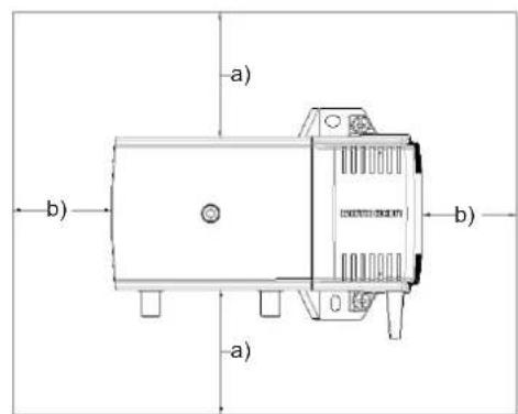
a) Distances to boundary surfaces: ≥ 150 mm
b) distances to boundary surfaces: ≥ 50 mm
Block diagram
![graph TD A["Input Output 5 - 1006 MHz"] --> B["85 - 1006 MHz"] B --> C["Attenuation 0 - 18 dB"] B --> D["Attenuation 5 - 65 MHz"] C --> E["dB Attenuation"] D --> F["dB Pre-emphasis"] E --> G["Interstage pre-emphasis"] F --> G G --> H["6 dB"] G --> I["0 dB"] H --> J["Pre-emphasis"] I --> J J --> K["6…](/content/2026/06/1267900/images/f5400caf643097b498260dfd030bd6e4ff90bebbc0c8a6a9f42886130ab81ce8.jpg)
Connection examples
Standard in-house distribution network for 1-4 connections with VOS 20/RA-1G

KAZ 11 (optional)
Standard in-house distribution network for 8 connections with VOS 29/RA-1G

KAZ 11 (optional)
Technical data
| Type VOS 20/RA-1G VOS 29/RA-1G | |||
| Order no. | 20910031 20910032 | ||
| Forward path | |||
| Frequency range MHz 85-1,006 | |||
| Gain dB 22 30 | |||
| Max. operational level CENELEC 42 channels (60 dB CTB/CSO) dBμV 96 | |||
| Noise figure | dB | 6 | |
| Gain setting range (on input) | dB | 0-18 | |
| Equalisation setting range (on input) | dB | 0-15 | |
| Setting range interstage equaliser 1) | dB | 0/6 | |
| Return path | |||
| Frequency range MHz 5-65 | |||
| Gain dB 20 25 | |||
| Gain setting range (on output) 2) | dB | 0-18 | |
| Gain setting range (on input) 1) | dB | 0/10 | |
| Equalisation setting range (on input) 1) | dB | 6 | |
| Noise figure | dB | 5 | |
| Max. output level (60 dB IMod3/IMod2) | dBμV | 116/106 | |
| Input level density (CINR: 50 dB) | dBμV | Typ. -8 | |
| Dynamic range (input level density) | dB | 22 | |
| Maximum output level as per KDG 1TS 140 (medium system load) | dBμV | 120 | |
| Classification to KDG 1 TS 140 | B (1.1) | B (3.1) | |
| General | |||
| Nominal input voltage | VAC | 230 (50/60 Hz) | |
| Power consumption | W | 4.5 | |
| Operational display | Green LED | ||
| RF connections | F-type connectors | ||
| Protection class/protection category (to EN 60529) | II / IP30 | ||
| Temperature range | °C | -20 to +55 | |
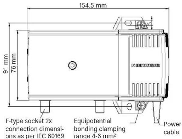
| Dimensions | mm | 105 x 155 x 54 | |
| Packing unit/weight | pc./kg | 1 (10)/0.8 | |
11 Settable using bridging plugs
2) The attenuator is set to max. attenuation in the delivery status.

Electronic equipment is not domestic waste - it must be disposed of properly in accordance with directive 2002/96/EC OF THE EUROPEAN PARLIAMENT AND THE COUNCIL dated 27th January 2003 concerning used electrical and electronic appliances.
At the end of its service life, take this device for disposal at a designated public collection point.


Brand : KATHREIN
Model : VOS 20/RA-1G
Category : TV signal amplifier