
EXE 2512 - TV signal amplifier KATHREIN - Free user manual and instructions
Find the device manual for free EXE 2512 KATHREIN in PDF.


| Product Type | TV Signal Amplifier |
| Brand | Kathrein |
| Model | EXE 2512 |
| Dimensions (approx) | 150 x 80 x 40 mm |
| Weight (approx) | 200 g |
| Power Supply | 12 V DC via external adapter |
| Frequency Range | 47 – 862 MHz |
| Gain | Up to 20 dB (adjustable) |
| Number of Inputs | 1 |
| Number of Outputs | 2 (1 for TV, 1 for loop-through) |
| Impedance | 75 Ω |
| Noise Figure | < 4 dB |
| Mounting | Wall-mountable (brackets included) |
| Operating Temperature | 0°C to +40°C |
| Maintenance & Cleaning | Wipe with a soft, dry cloth. Do not use liquids. |
| Safety | Disconnect from power before cleaning. Keep away from moisture. |
| Spare Parts / Reparability | No user-serviceable parts inside. Contact Kathrein service for repairs. |
| General Information | Amplifies terrestrial TV and radio signals. Suitable for indoor use. |
Frequently Asked Questions - EXE 2512 KATHREIN
User questions about EXE 2512 KATHREIN
0 question about this device. Answer the ones you know or ask your own.
Ask a new question about this device
Download the instructions for your TV signal amplifier in PDF format for free! Find your manual EXE 2512 - KATHREIN and take your electronic device back in hand. On this page are published all the documents necessary for the use of your device. EXE 2512 by KATHREIN.
USER MANUAL EXE 2512 KATHREIN
Sat-IF distribution system (4 x Sat-IF) Single-cable multi-switch

Digital Video Broadcasting
Features single-cable multi-switch
■ Cascadable single-cable multi-switches for distribution of digital Sat-IF signals (four Sat polarities) and terrestrial signals via one cable to up to 12 receivers
■ No limitation in the number of programmes - the complete programme range of one satellite is distributed
■ The selected transponder is transmitted by the multi-switch on a fixed frequency (userband), controlled by the receiver with a DiSEqC™ command set conforming to EN 50494
■ The multi-switch supports the extended single-cable set of commands SCD2 conforming to prTS 50607
■ Terrestrial signals can be received even when the satellite receiver is switched off
■ Each receiver is assigned a fixed subscriber frequency (userband); a twin receiver requires two subscriber frequencies
■ PIN Code: Protects the user frequency from being accessed by another user. This allows installation in an apartment building


■ Integrated AGC (Automatic Gain Control) ensures a constant output level in the Sat-IF range
■ EXE 2512 single-cable multi-switches and additional loop-through multi-switches such as EXE 259, EXR 2554, EXR 2558 and EXR 2542 can be combined as desired.
■ Up to eight multi-switches can be cascaded
■ For indoor installation
CEA
CLASS
EXE 1512
■ Single-cable multi-switch for up to 12 receivers, with an integrated power supply unit for LNB supply
■ Low power consumption due to highly efficient, short-circuit proof switched-mode power supply unit in compliance with ERP guideline and energy-saving concept (the single-cable multi-switch is switched off whenever the connected receiver is switched off)
■ Kathrein Power Saving: LNB supply is switched off as soon as all receivers connected to the EXE 1512 or in the cascade are inactive. This function can be deactivated; e.g. if loop-through multi-switches without Kathrein Power Saving are used in the cascade
■ LNB remote feeding via the horizontal low input. Kathrein Power Saving signalling over the vertical low trunk. All other inputs are voltage-free
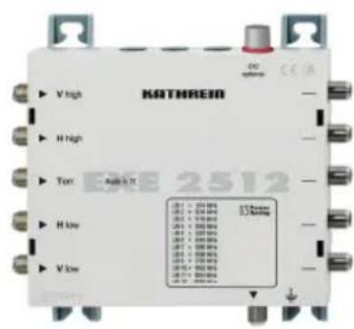
EXE 2512
■ Loop-through multi-switch to extend a single-cable system for an additional 12 receivers
■ Kathrein Power Saving: As soon as all receivers are inactive, a signal is sent to the end multi-switch via the vertical low trunk which then cuts off the LNB voltage supply.
■ Optional powering using the NCF 18. Due to the energy-saving concept, the multi-switch consumes no energy from the NCF 18 if no receivers are switched on.

Installation and Safety

- The equipment described is designed solely for the installation of satellite receiver systems.
- Any other use or failure to comply with these instructions will void the warranty or guarantee.
- The equipment may only be installed in dry areas indoors. Do not install on or against highly combustible materials.
- The equipment must be provided with an earthing wire (Cu, at least 4mm^2 ).
- The safety regulations set out in the current EN 60728-11 and EN 60065 standards must be complied with.
• Fixings: Screws, max. ∅: 4 mm - Connectors: RF connector 75 Ω (series F) according to EN 61169-24.
- Unused RF ports must be terminated with 75 resistors (e.g. EMK 03).

- An inner cable conductor diameter greater than 1.2 mm, or the presence of burrs may damage the sockets on the unit.

Diameter 0.6-1.2 mm free of burrs

natural_image
Simple line drawing of a mechanical component with a coiled spring and threaded end (no text or symbols)Current-carrying device
- Do not open the unit or tamper with it!
- When working on the system always unplug the power supply unit from the wall socket!
- The device is intended only for wall mounting! Do not install the device lying flat at or on its top, or operate it in this position.
- Ensure adequate clearance! Clearance all round at least 5 cm!
- Free circulation of air must be possible to discharge the heat emitted by the unit. Danger of overheating!
- Ambient temperature range -20 to +55°C

Caution:
- No liquid-fi lled items may be placed on top of the power supply unit.
- The power supply unit must not be exposed to dripping or splashing water.
- The mains plug must be easily accessible and operable.
- The only reliable method of disconnecting the unit from the mains is to unplug it.
Kathrein Power Saving
If an EXE 1512 is operated alone or together with other multi-switches that bear the Kathrein Power Saving logo, Kathrein Power Saving can be activated by setting the stand-by switch to "ON". If a receiver in the cascade is switched on, the LNB is powered through the end multi-switch.

Multi-switches without Kathrein Power Saving do not give signalling to the
end multi-switch. The stand-by switch must be set to "OFF" for permanent powering of the LNB.
PIN code protection
The multi-switch is protected by a PIN code in order to prevent the set userband from being used/disturbed by another subscriber. This should be specified in the receiver settings. A fixed PIN has been assigned to each userband.
| UB 1 | UB 2 | UB 3 | UB 4 | UB 5 | UB 6 | UB 7 | UB 8 | UB 9 | UB 10 | UB 11 | UB 12 | |||
| Frequency (MHz) | 974 | 1076 | 1178 | 1280 | 1382 | 1484 | 1586 | 1688 | 1790 | 1892 | 1994 | 2096 | ||
| PIN | 151 | 052 | 133 | 124 | 205 | 196 | 187 | 178 | 099 | 232 | 198 | 111 |
Notes
Only use splitters without diodes (EBC 110 or EBC 114). The required diode protection is provided by outlets from the ESU series.
It is especially important to make sure that each userband is assigned only once, since otherwise the receivers will generate mutual interference. The frequencies are allocated on the receivers settings menu. Depending on the type, this may be performed manually or automatically.

It is recommended that the wall sockets with the shorter length connections are assigned to the higher frequencies. By definition the system is designed so that single-cable units are supplied with 14 V DC. The power supply is briefly switched to 18 V DC if control signals similar to DiSEqC ^™ have to be transmitted. Continuous application of 18 V would block the system. For this reason we recommend the use of ESU series outlets, which are equipped for switching off electronically.
The receivers that are connected must be designed for single-cable operation conforming to EN 50494. To be able to exploit user bands 9-12, the receiver must in addition satisfy the new single cable standard SCD2 to prTS 50607.
System example (symbolic representation)

flowchart
graph TD
    A["SatAn®"] -->|UAS 584/585| B["Sat-IF 950-2150 MHz"]
    B --> C["ESU 37 Twin"]
    B --> D["ESU 37 Twin"]
    B --> E["ESU 37 Twin"]
    B --> F["ESU 36 Twin"]
    B --> G["ESU 36 Single"]
    B --> H["ESU 36 Single"]
    B --> I["ESU 33 Single"]
    B --> J["ESU 33 Single"]
    B --> K["ERA 14"]
    C --> L["EBC 110"]
    D --> L
    E --> L
    F --> L
    G --> L
    H --> L
    I --> L
    J --> L
    K --> L
    L --> M["ESU 37 Single"]
    L --> N["ESU 37 Single"]
    L --> O["ESU 36 Single"]
    L --> P["ESU 36 Single"]
    L --> Q["ESU 33 Single"]
    L --> R["ESU 33 Single"]
    L --> S["ERA 14"]
    style A fill:#f9f,stroke:#333
    style B fill:#ccf,stroke:#333
    style C fill:#cfc,stroke:#333
    style D fill:#cfc,stroke:#333
    style E fill:#cfc,stroke:#333
    style F fill:#cfc,stroke:#333
    style G fill:#cfc,stroke:#333
    style H fill:#cfc,stroke:#333
    style I fill:#cfc,stroke:#333
    style J fill:#cfc,stroke:#333
    style K fill:#cfc,stroke:#333
    style L fill:#fcc,stroke:#333
    style M fill:#fcc,stroke:#333
    style N fill:#fcc,stroke:#333
    style O fill:#fcc,stroke:#333
    style P fill:#fcc,stroke:#333
    style Q fill:#fcc,stroke:#333
    style R fill:#fcc,stroke:#333
    style S fill:#fcc,stroke:#333
*) EMU 250 connector
**) KAZ 11/KAZ 12 over-voltage protector
Technical data
| Type EXE 1512 EXE 2512 | ||||||
| Order no. 20510093 20510094 | ||||||
| Subscriber connections 1 x 12 1 x 12 | ||||||
| Inputs 1 x terrestr. 4 x Sat-IF 1 x terrestr. 4 x Sat-IF | ||||||
| Frequency range MHz 5-862 950-2,150 5-862 950-2,150 | ||||||
| Through loss dB -- 1.5 2 | ||||||
| Tap loss (terrestrial) | dB | 9 | - | 11 | - | |
| Output level Sat (AGC) | dBμV | - | 88 | - | 88 | |
| Decoupling horiz./vert. | dB | - | 30 | - | 30 | |
| Trunk decoupling | dB -- - | 40 | ||||
| Input level Sat | dBμV | - | 55-80 | - | 55-80 | |
| Subscriber frequency/user band | Receiver 1 | MHz | 974/1 | 974/1 | ||
| Receiver 2 | 1,076/2 | 1,076/2 | ||||
| Receiver 3 | 1,178/3 | 1,178/3 | ||||
| Receiver 4 | 1,280/4 | 1,280/4 | ||||
| Receiver 5 | 1,382/5 | 1,382/5 | ||||
| Receiver 6 | 1,484/6 | 1,484/6 | ||||
| Receiver 7 | 1,586/7 | 1,586/7 | ||||
| Receiver 8 | 1,688/8 | 1,688/8 | ||||
| Receiver 9 | 1,790/9 | 1,790/9 | ||||
| Receiver 10 | 1,892/10 | 1,892/10 | ||||
| Receiver 11 | 1,994/11 | 1,994/11 | ||||
| Receiver 12 | 2,096/12 | 2,096/12 | ||||
| Screening factor | dB | 5-300 MHz > 85; 300-470 MHz > 80470-1,000 MHz > 75; 1,000-2,150 MHz > 55 | ||||
| Permissible supply voltage at the subscriber output | V | 12-14 | 12-14 | |||
| Max. current drain through subscriber output | mA | 10 | With power supply unit 10/without power supply unit 490 | |||
| Nominal input voltage | V | 230 (47-63 Hz) | - | |||
| Permissible input voltage range | V | 207-253 | - | |||
| Nominal input power at 0/150/500 mA load | W | 6.2/9.5/17 | - | |||
| Voltage secondary (input horiz. low) | V | 18 | - | |||
| Max. remote feed current (input horiz. low) | mA | 500 | - | |||
| Max. permissible remote feed current per trunk | mA | - | 1,000 | |||
| Protection class/protection type | II (insulated)/IP 30 | -/IP 30 | ||||
| Permissible ambient temperature | °C | - 20 to + 55 | - 20 to + 55 | |||
| Connections | F-type connectors | F-type connectors | ||||
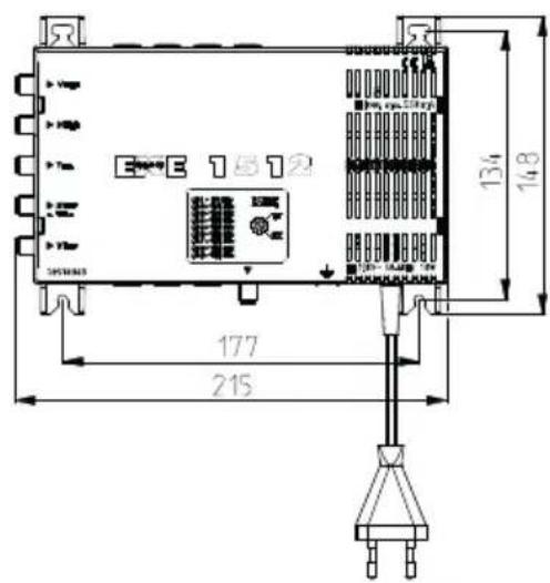
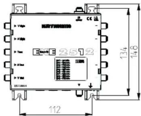
| Dimensions | mm | 215 x 148 x 43 | 160 x 148 x 43 | |||
| Packing unit/weight | pc./kg | 1 (10)/0.65 | 1 (10)/0.45 | |||
*) All 12 subscriber frequencies/userbands in operation
Possible causes of faults, and their remedies
| Problem Possible cause: Solution | ||
| Permanent message: "poor/no signal" | No voltage from receiver | Short circuit on the receiver - multi-switch connection. Receiver is not in single-cable mode. Outlet blocks permanent 18 V. |
| Wrong single-cable command | Receiver is not in single-cable mode | |
| Poor DiSEqCTM signal | Power consumption too high. Use distribution material without diodes. Use NCF 18 power supply unit for EXE 2512. | |
| Wrong PIN Code Check or deactivate PIN code number | ||
| Wrong assignment | UB and frequency do not match. Warning: SCR no. is not equivalent to UB no. | |
| No voltage on the LNB | EXE 1512 mains plug not plugged. Short circuit on the receiver - LNB connection | |
| If the LNB places too great a load on the trunk VL, connect DC block EMU 12, BN: 273281 to the cascade input. | ||
| Only UB 9-12: "poor/ no signal" | Receiver does not support SCD2 conforming to prTS50607 | If possible, perform software update on receiver |
| Short message: "Poor/no signal" or picture wobbles in regular intervals | Another subscriber has accessed the same UB | Check menu settings of all connected receivers. Check that frequencies are assigned to one receiver only. |
| Loop-through multi-switches without Kathrein Power Saving do not or only sometimes function | Stand-by switch on "ON" | Switch off stand-by function. Stand-by switch to "OFF" |

Electronic equipment is not domestic waste - it must be disposed of properly in accordance with directive 2002/96/EC OF THE EUROPEAN PARLIAMENT AND THE COUNCIL dated 27^th January 2003 concerning used electrical and electronic appliances. At the end of its service life, take this device for disposal at a designated public collection point.


Brand : KATHREIN
Model : EXE 2512
Category : TV signal amplifier