
GOF 900 CE Professional - Slicer BOSCH - Free user manual and instructions
Find the device manual for free GOF 900 CE Professional BOSCH in PDF.


| Product Type | Slicer (Router) |
| Model | GOF 900 CE Professional |
| Brand | Bosch |
| Dimensions (L x W x H) | 300 x 200 x 250 mm |
| Weight | 4.5 kg |
| Power Supply | 900 W, 230 V AC |
| Main Functions | Routing, edge profiling, slot cutting, grooving |
| Electronic Speed Control | Constant Electronic (CE) for consistent speed under load |
| Soft Start | Yes, for smooth startup |
| Safety Features | Restart protection, electronic safety clutch |
| Maintenance | Clean with dry cloth; inspect carbon brushes periodically |
| Dust Extraction Adapter | Included for connecting to vacuum |
| Spindle Lock | For easy bit changes |
| Collets | 6 mm, 8 mm (1/4", 5/16") included |
| Accessories Included | Parallel guide, dust extraction adapter, wrench, collets |
| Spare Parts Availability | Available at Bosch service centers |
| Device Class | Professional (Blue line) |
Frequently Asked Questions - GOF 900 CE Professional BOSCH
User questions about GOF 900 CE Professional BOSCH
0 question about this device. Answer the ones you know or ask your own.
Ask a new question about this device
Download the instructions for your Slicer in PDF format for free! Find your manual GOF 900 CE Professional - BOSCH and take your electronic device back in hand. On this page are published all the documents necessary for the use of your device. GOF 900 CE Professional by BOSCH.
USER MANUAL GOF 900 CE Professional BOSCH
OBJ DOKU-3252-003, Im Page 1 Tuesday, September 2, 2008 8:59 AM

Robert Bosch GmbH
1 609 929 N93 | (2.9.08) Bosch Power Tools
4 |




1 609 929 N93 | (2.9.08) Bosch Power Tools



5



1 609 929 N93 | (2.9.08) Bosch Power Tools


N

Deutsch | 7
Sicherheitshinweise
Dr. Egbert Schneider Senior Vice President Engineering
Dr. Eckerhard Strötgen Head of Product Certification
ppa. Aneka i.v. Nuoyen
Robert Bosch GmbH, Power Tools Division D-70745 Leinfelden-Echterdingen 31.07.2008
Montage
General Power Tool Safety Warnings
WARNING
Read all safety warnings and all instructions. Failure to follow
the warnings and instructions may result in electric shock, fire and/or serious injury.
Save all warnings and instructions for future reference.
The term "power tool" in the warnings refers to your mains-operated (corded) power tool or battery-operated (cordless) power tool.
1) Work area safety
a) Keep work area clean and well lit. Cluttered or dark areas invite accidents.
b) Do not operate power tools in explosive atmospheres, such as in the presence of flammable liquids, gases or dust. Power tools create sparks which may ignite the dust or fumes.
c) Keep children and bystanders away while operating a power tool. Distractions can cause you to lose control.
2) Electrical safety
a) Power tool plugs must match the outlet. Never modify the plug in any way. Do not use any adapter plugs with earthed (grounded) power tools. Unmodified plugs and matching outlets will reduce risk of electric shock.
b) Avoid body contact with earthed or grounded surfaces, such as pipes, radiators, ranges and refrigerators. There is an increased risk of electric shock if your body is earthed or grounded.
c) Do not expose power tools to rain or wet conditions. Water entering a power tool will increase the risk of electric shock.
d) Do not abuse the cord. Never use the cord for carrying, pulling or unplugging the power tool. Keep cord away from heat, oil, sharp edges and moving parts. Damaged or entangled cords increase the risk of electric shock.
e) When operating a power tool outdoors, use an extension cord suitable for outdoor use. Use of a cord suitable for outdoor use reduces the risk of electric shock.
f) If operating a power tool in a damp location is unavoidable, use a residual current device (RCD) protected supply. Use of an RCD reduces the risk of electric shock.
3) Personal safety
a) Stay alert, watch what you are doing and use common sense when operating a power tool. Do not use a power tool while you are tired or under the influence of drugs, alcohol or medication. A moment of inattention while operating power tools may result in serious personal injury.
b) Use personal protective equipment. Always wear eye protection. Protective equipment such as dust mask, non-skid safety shoes, hard hat, or hearing protection used for appropriate conditions will reduce personal injuries.
c) Prevent unintentional starting. Ensure the switch is in the off-position before connecting to power source and/or battery pack, picking up or carrying the tool. Carrying power tools with your finger on the switch or energising power tools that have the switch on invites accidents.
d) Remove any adjusting key or wrench before turning the power tool on. A wrench or a key left attached to a rotating part of the power tool may result in personal injury.
e) Do not overreach. Keep proper footing and balance at all times. This enables better control of the power tool in unexpected situations.
f) Dress properly. Do not wear loose clothing or jewellery. Keep your hair, clothing and gloves away from moving parts. Loose clothes, jewellery or long hair can be caught in moving parts.
20 | English
g) If devices are provided for the connection of dust extraction and collection facilities, ensure these are connected and properly used. Use of dust collection can reduce dust-related hazards.
4) Power tool use and care
a) Do not force the power tool. Use the correct power tool for your application. The correct power tool will do the job better and safer at the rate for which it was designed.
b) Do not use the power tool if the switch does not turn it on and off. Any power tool that cannot be controlled with the switch is dangerous and must be repaired.
c) Disconnect the plug from the power source and/or the battery pack from the power tool before making any adjustments, changing accessories, or storing power tools. Such preventive safety measures reduce the risk of starting the power tool accidentally.
d) Store idle power tools out of the reach of children and do not allow persons unfamiliar with the power tool or these instructions to operate the power tool. Power tools are dangerous in the hands of untrained users.
e) Maintain power tools. Check for misalignment or binding of moving parts, breakage of parts and any other condition that may affect the power tool's operation. If damaged, have the power tool repaired before use. Many accidents are caused by poorly maintained power tools.
f) Keep cutting tools sharp and clean. Properly maintained cutting tools with sharp cutting edges are less likely to bind and are easier to control.
g) Use the power tool, accessories and tool bits etc. in accordance with these instructions, taking into account the working conditions and the work to be performed. Use of the power tool for operations different from those intended could result in a hazardous situation.
5) Service
a) Have your power tool serviced by a qualified repair person using only identical replacement parts. This will ensure that the safety of the power tool is maintained.
Safety Warnings for Routers
The allowable speed of the router bit must be at least as high as the maximum speed listed on the power tool. Accessories that rotate faster than permitted can be destroyed.
▶ Router bits or other accessories must fit exactly in the tool holder (collet) of your machine. Routing bits that do not fit precisely in the tool holder of the machine rotate irregularly, vibrate heavily and can lead to loss of control.
▶ Apply the machine to the workpiece only when switched on. Otherwise there is danger of kickback when the cutting tool jams in the workpiece.
- Keep your hands away from the cutting area and the cutting disc. Hold the auxiliary handle with your second hand. When both hands hold the machine, they cannot be injured by the cutting disc.
▶ Never cut over metal objects, nails or screws. The router bit can become damaged and lead to increased vibrations.
Hold the power tool only by the insulated gripping surfaces when performing an operation where the cutting tool may contact hidden wiring or its own cord. Contact with a "live" wire will also make exposed metal parts of the power tool "live" and shock the operator.
▶ Use appropriate detectors to determine if utility lines are hidden in the work area or call the local utility company for assistance. Contact with electric lines can lead to fire and electric shock. Damaging a gas line can lead to explosion. Penetrating a water line causes property damage or may cause an electric shock.
▶ Do not use blunt or damaged router bits. Blunt or damaged router bits cause increased friction, can become jammed and lead to imbalance.
When working with the machine, always hold it firmly with both hands and provide for a secure stance. The power tool is guided more secure with both hands.
- Secure the workpiece. A workpiece clamped with clamping devices or in a vice is held more secure than by hand.
- Keep your workplace clean. Blends of materials are particularly dangerous. Dust from light alloys can burn or explode.
▶ Always wait until the machine has come to a complete stop before placing it down. The tool insert can jam and lead to loss of control over the power tool.
▶ Never use the machine with a damaged cable. Do not touch the damaged cable and pull the mains plug when the cable is damaged while working. Damaged cables increase the risk of an electric shock.
Functional Description

Read all safety warnings and all instructions. Failure to follow the warnings and instructions may result in electric shock, fire and/or serious injury.
While reading the operating instructions, unfold the graphics page for the machine and leave it open.
Intended Use
The machine is intended for routing grooves, edges, profiles and elongated holes as well as for copy routing in wood, plastic and light building materials, while resting firmly on the workpiece.
With reduced speed and with appropriate routing bits, non-ferrous alloys can also be machined.
Product Features
The numbering of the product features refers to the illustration of the machine on the graphics page.
1 Right handle
2 Lock-on button for On/Off switch
3 Thumbwheel for speed preselection
4 Spindle lock lever
5 Wing bolt for guide rods of parallel guide (2x)*
6 Chip shield
7 Router bit*
8 Seat for parallel guide rods
9 Guide plate
10 Step buffer
11 Adjusting screws for step buffer
12 Base plate
13 Dust boot
14 Wing bolt for depth stop adjustment
15 Depth stop
16 Slide with index mark
17 Left handle
18 Scale for depth-of-cut
19 Scale for depth-of-cut fine adjustment
20 Adjustment knob for depth-of-cut fine adjustment
21 Mark for zeroing
22 Release lever
23 Tightening nut with collet
24 On/Off switch
25 Open-end spanner, size 24 mm*
26 Extraction hose (∅ 35 mm)*
27 Extraction adapter*
28 Knurled screw for extraction adapter (2x)*
29 Parallel guide*
30 Guide rod for parallel guide (2x)*
31 Wing bolt for fine adjustment of parallel guide (2x)*
32 Wing bolt for coarse adjustment of parallel guide (2x)*
33 Fine-adjustment knob for parallel guide*
34 Edge guide for parallel guide*
22 | English
35 Extraction adapter for parallel guide*
36 Router compass/guide-rail adapter*
37 Router compass handle*
38 Wing bolt for coarse adjustment of router compass (2x)*
39 Wing bolt for fine adjustment of router compass (1x)*
40 Fine-adjustment knob for router compass*
41 Centring screw*
42 Base spacer
(included in the "router compass" set)*
43 Guide rail*
44 Guide bushing adapter
45 Fastening screw for guide bushing adapter (2x)
46 Release lever for guide bushing adapter
47 Guide bushing
48 Pan head screw for guide plate
49 Countersunk head screw for guide plate
50 Centring pin
*The accessories illustrated or described are not included as standard delivery.
Technical Data
| Plunge router GOF 900 CE | Professional | GOF 1300 CE Professional | |
| Article number | 0 601 614 6.. | 0 601 613 6.. | |
| Rated power input | W 900 1300 | ||
| No-load speed | min1 | 12000-24000 | 12000 - 24000 |
| Speed preselection | ● | ● | |
| Constant electronic control | ● | ● | |
| Connection for dust extraction | ● | ● | |
| Tool holder | mm | 6-8 | 6-12.7 |
| inch | 1/4 | 1/4-1/2 | |
| Plunge depth | mm | 50 | 58 |
| Weight according to EPTA-Procedure 01/2003 | kg | 3.5 | 4.8 |
| Protection class | ☐/II | ☐/II | |
The values given are valid for nominal voltages [U] of 230/240 V. For lower voltage and models for specific countries, these values can vary.
Please observe the article number on the type plate of your machine. The trade names of the individual machines may vary.
Noise/Vibration Information
Measured values determined according to EN 60745 (chip board).
Typically the A-weighted noise levels of the product are: Sound pressure level 89 dB(A); Sound power level 100 dB(A). Uncertainty K = 3 dB.
Wear hearing protection!
Vibration total values (triax vector sum) determined according to EN 60745: Vibration emission value ah=5.5\ m/s2 , Uncertainty K=2.5\ m/s2 .
The vibration emission level given in this information sheet has been measured in accordance with a standardised test given in EN 60745 and may be used to compare one tool with another. It may be used for a preliminary assessment of exposure.
The declared vibration emission level represents the main applications of the tool. However if the tool is used for different applications, with different accessories or poorly maintained, the vibration emission may differ. This may significantly increase the exposure level over the total working period.
An estimation of the level of exposure to vibration should also take into account the times when the tool is switched off or when it is running but not actually doing the job. This may significantly reduce the exposure level over the total working period.
Identify additional safety measures to protect the operator from the effects of vibration such as: maintain the tool and the accessories, keep the hands warm, organisation of work patterns.
Declaration of Conformity CE
We declare under our sole responsibility that the product described under "Technical Data" is in conformity with the following standards or standardization documents: EN 60745 according to the provisions of the directives 2004/108/EC, 98/37/EC (until 28 Dec 2009), 2006/42/EC (from 29 Dec 2009).
Technical file at: Robert Bosch GmbH, PT/ESC, D-70745 Leinfelden-Echterdingen
Dr. Egbert Schneider Senior Vice President Engineering
Dr. Eckerhard Strötgen Head of Product Certification
ppa. dawna i.v. Mozyen
Robert Bosch GmbH, Power Tools Division D-70745 Leinfelden-Echterdingen 31.07.2008
Assembly
Inserting a Router Bit (see figure A)
▶ Before any work on the machine itself, pull the mains plug.
It is recommended to wear protective gloves when inserting or replacing router bits.
Depending on the application, router bits are available in the most different designs and qualities.
Router bits made of high speed steel (HSS) are suitable for the machining of soft materials, e. g. softwood and plastic.
Carbide tipped router bits (HM) are particularly suitable for hard and abrasive materials, e. g. hardwood and aluminium.
Original router bits from the extensive Bosch accessories program are available at your specialist shop.
Only use clean router bits that are in perfect condition.
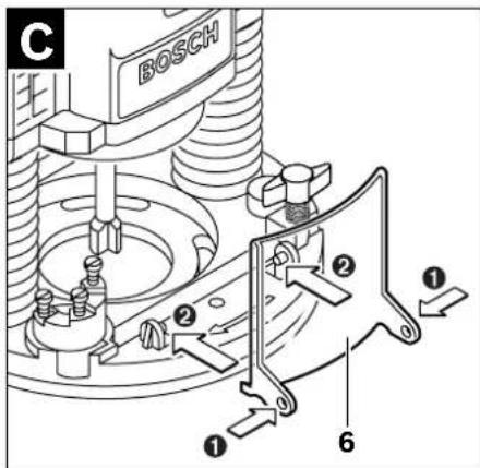
- Fold the chip shield 6 down.
- Push the spindle lock lever 4 in clockwise direction and hold it in this position (0). If required, turn the motor spindle by hand until it is locked.
- Loosen the tightening nut 23 with the open-end spanner 25 (size 24 mm) by turning in anticlockwise direction (②).
- Insert the router bit into the collet. The shank of the router bit must be immersed at least 20 mm into the collet.
- Tighten the tightening nut 23 with the open-end spanner 25 (size 24 mm) by turning in clockwise direction. Release the spindle lock lever 4.
- Fold the chip shield 6 up again.
▶ Do not insert a router bit with a diameter larger than 50 mm when the guide bushing is not mounted. Such router bits do not fit through the base plate.
▶ Do not tighten the tightening nut of the collet without a router bit inserted. Otherwise the collet can be damaged.
Dust/Chip Extraction (see figure B)
Dusts from materials such as lead-containing coatings, some wood types, minerals and metal can be harmful to one's health. Touching or breathing-in the dusts can cause allergic reactions and/or lead to respiratory infections of the user or bystanders.
24 | English
Certain dusts, such as oak or beech dust, are considered as carcinogenic, especially in connection with wood-treatment additives (chromate, wood preservative). Materials containing asbestos may only be worked by specialists.
- Use dust extraction whenever possible.
- Provide for good ventilation of the working place.
- It is recommended to wear a P2 filter-class respirator.
Observe the relevant regulations in your country for the materials to be worked.
Mounting the Extraction Adapter
The extraction adapter 27 can be mounted with the hose connection to the front or to the rear. When the guide bushing adapter 44 is mounted, it is possible that the guide bushing adapter must be turned by 180° so that the extraction adapter 27 does not touch the release lever 46. When mounting with the hose connection in front, the chip shield 6 must be removed first. Fasten the extraction adapter 27 with the 2 knurled screws 28 to the base plate 12.
Connecting the Dust Extraction
Insert an extraction hose ( 35 mm) 26 (accessory) into the mounted extraction adapter. Connect the extraction hose 26 to a vacuum cleaner (accessory).
The machine can be plugged directly into the receptacle of a Bosch all-purpose vacuum cleaner with remote starting control. The vacuum cleaner starts automatically when the machine is switched on.
The vacuum cleaner must be suitable for the material being worked.
When vacuuming dry dust that is especially detrimental to health or carcinogenic, use a special vacuum cleaner.
Mounting the Chip Shield (see figure C)
Insert the chip shield 6 from the front into the guide in such a manner that it engages. To remove the chip shield, grasp it by the sides and pull it off toward the front.
Operation
Starting Operation
▶ Observe correct mains voltage! The voltage of the power source must agree with the voltage specified on the nameplate of the machine. Power tools marked with 230 V can also be operated with 220 V.
Preselecting the Speed
The required speed can be preselected with the thumbwheel 3 (also while running).
1 - 2 low speed
3 - 4 medium speed
5-6 high speed
The values shown in the chart are standard values. The necessary speed depends on the material and the operating conditions, and can be determined by practical testing.
| Material Router bit dl- ameter (mm) | Thumb- wheel 3 | |
| Hardwood (Beech) | 4-10 | 5-6 |
| 12-20 | 3-4 | |
| 22-40 | 1-2 | |
| Softwood (Pine) | 4-10 | 5-6 |
| 12-20 | 3-6 | |
| 22-40 | 1-3 | |
| Particle Board | 4-10 | 3-6 |
| 12-20 | 2-4 | |
| 22-40 | 1-3 | |
| Plastics | 4-15 | 2-3 |
| 16-40 | 1-2 | |
| Aluminium | 4-15 | 1-2 |
| 16-40 | 1 | |
After longer periods of working at low speed, allow the machine to cool down by running it for approx. 3 minutes at maximum speed with no load.
Switching On and Off
Adjust the depth-of-cut before switching on or off; see Section "Adjusting the Depth-of-cut".
To start the machine, press the On/Off switch 24 and keep it pressed.
To lock the pressed On/Off switch 24, press the lock-on button 2.
To switch off the machine, release the On/Off switch 24 or when it is locked with the lock-on button 2, briefly press the On/Off switch 24 and then release it.
Constant Electronic Control
Constant electronic control holds the speed constant at no-load and under load, and ensures uniform working performance.
Soft Starting
The electronic soft starting feature limits the torque upon switching on and increases the working life of the motor.
Adjusting the Depth-of-cut (see figure D)
The adjustment of the depth-of-cut may only be carried out when the router is switched off.
For coarse adjustment of the depth-of-cut, proceed as follows:
- Place the machine with the router bit mounted on the workpiece to be machined.
- Set the fine-adjustment path to the centre position with the adjustment knob 20. For this, turn the adjustment knob 20 until the marks 21 match as shown in the figure. Afterwards, set the scale 19 to "0".

- Set the step buffer 10 to the lowest position; the step buffer engages noticeably.
-
Loosen the wing bolt for the depth stop 14 so that the depth stop 15 can be moved freely.
-
Push the release lever 22 downward and slowly lower the plunge router until the router bit 7 touches the surface of the workpiece. Let go of the release lever 22 again to lock this plunging depth.
- Push the depth stop 15 downward until it rests on the step buffer 10. Set the slide with the index mark 16 to the "0" position on the scale for the depth-of-cut adjustment 18.
- Set the depth stop 15 to the required depth-of-cut and tighten the wing bolt for the depth stop 14. Pay attention not to misadjust the slide with the index mark 16 again.
- Push the release lever 22 and guide the plunge router to the uppermost position.
For deep cuts, it is recommended to carry out several cuts, each with little material removal. By using the step buffer 10, the cutting process can be divided into several steps. For this, adjust the desired depth-of-cut with the lowest step of the step buffer and select the higher steps first for the initial cuts. The clearance of the steps can be changed by screwing the adjusting screws 11 further in or out.
After a trial cut, the depth-of-cut can be set exactly to the desired measure by turning the adjustment knob 20; turn in clockwise direction to increase the cutting depth and in anticlockwise direction to decrease the cutting depth. The scale 19 can be used for guidance. One full turn corresponds with a setting range of 2.0 mm; a graduation mark on the top edge of the scale 19 corresponds with a 0.1 mm change of the setting range. The maximum setting range is ±8 mm.
Example: The desired depth-of-cut is to be 10.0 mm; the trial cut resulted in a cutting depth of 9.6 mm.
- Lift up the router and place e. g. a piece of scrap wood under the guide plate 9 so that the router bit 7 cannot touch the workpiece when lowering it. Push the release lever 22 down and slowly lower the plunge router until the depth stop 15 faces on the step buffer 10.
- Turn the scale 19 to "0" and loosen wing bolt 14.
26 | English
- Turn the adjustment knob 20 by 0.4 mm/4 graduation marks (difference from set to actual value) in clockwise direction and tighten the wing bolt 14.
- Check the selected depth-of-cut by carrying out another trial cut.
After adjusting the depth-of-cut, do not change the position of the slide 16 on the depth stop 15 any more, so that the actual cutting depth can be read on the scale 18.
Working Advice
▶ Protect router bits against shock and impact.
Direction of Feed and Routing Process (see figure E)
The routing process must always be carried out against the rotation direction of the router bit 7 (up-cutting motion). When routing in the direction with the rotation of the router (down-cutting), the machine can break loose, eliminating control by the user.
- Adjust the required depth-of-cut; see Section "Adjusting the Depth-of-cut".
- Place the machine with the router bit mounted on the workpiece to be machined and switch the power tool on.
- Push the release lever 22 down and slowly lower the plunge router until the adjusted depth-of-cut is reached. Let go of the release lever 22 again to lock this cutting depth.
- Carry out the routing process applying uniform feed.
- After finishing the cutting process, guide the plunge router upward again to the uppermost position.
- Switch the power tool off.
Routing with Auxiliary Guide (see figure F)
For working large workpieces, e. g. when routing grooves, a board or wood strip can be fastened to the workpiece as an auxiliary guide alongside which the router can be guided. Guide the router with the flattened side of the guide plate along the auxiliary guide.
Shaping or Molding Applications
For shaping or molding applications without the use of a parallel guide, the router bit must be equipped with a pilot or a ball bearing.
- Guide the switched on power tool from the side toward the workpiece until the pilot or the ball bearing of the router bit faces against the workpiece edge to be machined.
- Guide the power tool alongside the workpiece edge with both hands, paying attention that the router is positioned rectangular. Too much pressure can damage the edge of the workpiece.
Routing with Parallel Guide (see figure G)
Slide the parallel guide 29 with the guide rods 30 into the base plate 12 and tighten as required with the wing bolts 5. Additionally, the parallel guide can be adjusted lengthwise with the wing bolts 31 and 32.
Fine adjustment of the length is possible with the fine-adjustment knob 33 after loosening both wing bolts 31. One revolution corresponds with a setting range of 2.0 mm. One graduation mark on the fine-adjustment knob 33 changes the setting range by 0.1 mm.
The effective contact surface of the parallel guide can be adjusted with the edge guide 34. Guide the switched on power tool with uniform feed and lateral pressure on the parallel guide alongside the workpiece edge.
When routing with the parallel guide 29, the dust/chip extraction should take place via the special extraction adapter for the parallel guide 35. The extraction adapter 27 can remain mounted.
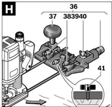
Routing with the Router Compass (see figure H)
The router compass/guide-rail adapter 36 can be used for circular routing jobs. Mount the router compass as shown in the figure.
Screw the centring screw 41 into the thread on the router compass. Insert the point of the centring screw into the centre of the circular arc to be routed, paying attention that point of the screw engages into the workpiece surface.
Coarsely adjust the required radius by moving the router compass and tighten the wing bolts 38 and 39.
The length can be fine adjusted with the fine-adjustment knob 40 after loosening the wing bolt 39. One revolution corresponds with a setting range of 2.0 mm. One graduation mark on the fine-adjustment knob 40 changes the setting range by 0.1 mm.
Guide the switched on power tool over the workpiece with the right handle 1 and the router compass handle 37.
Routing with Guide Rail (see figure 1)
Straight routing cuts can be carried out with help of the guide rail 43.
The base spacer 42 must be mounted in order to compensate the height difference.
Mount the router compass/guide-rail adapter 36 as shown in the figure.
Fasten the guide rail 43 to the workpiece with suitable clamping devices, e. g. screw clamps. Place the machine with the guide-rail adapter 36 mounted onto the guide rail.
Routing with Guide Bushing (see figures K-N)
The guide bushing 47 enables template and pattern routing on workpieces.
In order to use the guide bushing 47, the guide bushing adapter 44 must be inserted into the guide plate 9 first.
Place the guide bushing adapter 44 from above onto the guide plate 9 and tighten it firmly with the 2 fastening screws 45. Pay attention that the release lever for the guide bushing adapter 46 is freely movable.
Choose a suitable guide bushing, depending on the thickness of the template or the pattern. Because of the projecting height of the guide bushing, the template must have a minimum thickness of 8 mm.
Actuate the release lever 46 and insert the guide bushing 47 from below into the guide bushing adapter 44. Ensure that the encoding keys clearly engage in the grooves of the guide bushing.
▶ Select a router bit with a diameter smaller than the interior diameter of the guide bushing.
To ensure that the distance from router bit centre and guide bushing edge is uniform, the guide bushing and the guide plate can be adjusted to each other, if required.
- Push the release lever 22 down and guide the router to the stop in the direction of the base plate 12. Let go of the release lever 22 again, in order to lock this plunging depth.
- Unscrew the countersunk head screws 49. Screw the pan head screws 48 into the holes intended for this purpose in such a manner that the guide plate 9 can be moved freely.
- Insert the centring pin 50 into the tool holder as shown in the figure. Hand-tighten the tightening nut so that the centring pin can still be moved freely.
- Align the centring pin 50 and the guide bushing 47 to each other by slightly moving the guide plate 9.
- Tighten the pan head screws 48.
- Remove the centring pin 50 from the tool holder.
- Push the release lever 22 and guide the plunge router to the uppermost position.
For routing with the guide bushing 47 proceed as follows:
– Guide the switched on power tool with the guide bushing toward the template.
- Push the release lever 22 down and slowly lower the plunge router until the adjusted depth-of-cut is reached. Let go of the release lever 22 again to lock this cutting depth.
- Guide the switched on power tool with the protruding guide bushing alongside the template applying lateral pressure.
Maintenance and Service
Maintenance and Cleaning
▶ Before any work on the machine itself, pull the mains plug.
▶ For safe and proper working, always keep the machine and ventilation slots clean.
28 | English
In extreme working conditions, conductive dust can accumulate in the interior of the machine when working with metal. The protective insulation of the machine can be degraded. The use of a stationary extraction system is recommended in such cases as well as frequently blowing out the ventilation slots and installing a residual current device (RCD).
If the machine should fail despite the care taken in manufacturing and testing procedures, repair should be carried out by an after-sales service centre for Bosch power tools.
In all correspondence and spare parts order, please always include the 10-digit article number given on the type plate of the machine.
WARNING! Important instructions for connecting a new 3-pin plug to the 2-wire cable. The wires in the cable are coloured according to the following code:

Do not connect the blue or brown wire to the earth terminal of the plug.
Important: If for any reason the moulded plug is removed from the cable of this power tool, it must be disposed of safely.
After-sales Service and Customer Assistance
Our after-sales service responds to your questions concerning maintenance and repair of your product as well as spare parts. Exploded views and information on spare parts can also be found under:
www.bosch-pt.com
Our customer consultants answer your questions concerning best buy, application and adjustment of products and accessories.
Great Britain
Robert Bosch Ltd. (B.S.C.)
P.O. Box 98
Broadwater Park
North Orbital Road
Denham
Uxbridge
UB 9 5HJ
Tel. Service: +44 (0844) 736 0109
Fax: +44 (0844) 736 0146
Australia, New Zealand and Pacific Islands
Robert Bosch Australia Pty. Ltd.
Power Tools
Locked Bag 66
Clayton South VIC 3169
Customer Contact Center
Inside Australia:
Phone: +61 (01300) 307 044
Fax: +61 (01300) 307 045
Inside New Zealand:
Phone: +64 (0800) 543 353
Fax: +64 (0800) 428 570
Outside AU and NZ:
Phone: +61 (03) 9541 5555
www.bosch.com.au
Disposal
The machine, accessories and packaging should be sorted for environmental-friendly recycling.
Only for EC countries:
Do not dispose of power tools into household waste!
According the European Guideline 2002/96/EC for Waste Electrical and Electronic Equipment and its
implementation into national right, power tools that are no longer usable must be collected separately and disposed of in an environmentally correct manner.
Subject to change without notice.
Français | 29
Dr. Egbert Schneider Senior Vice President Engineering
Dr. Eckerhard Strötgen Head of Product Certification
ppa. Muenza i.v. Wuzyen
Robert Bosch GmbH, Power Tools Division D-70745 Leinfelden-Echterdingen 31.07.2008
Montage
Dr. Egbert Schneider Senior Vice President Engineering Dr. Eckerhard Strötgen Head of Product Certification
ppa. Aneka i.v. Nuoyen
Robert Bosch GmbH, Power Tools Division D-70745 Leinfelden-Echterdingen 31.07.2008
Montaje
Dr. Egbert Schneider Senior Vice President Engineering Dr. Eckerhard Strötgen Head of Product Certification
ppa. Aneka i.v. Nuoyen
Robert Bosch GmbH, Power Tools Division D-70745 Leinfelden-Echterdingen 31.07.2008
Montagem
Dr. Egbert Schneider Senior Vice President Engineering
Dr. Eckerhard Strötgen Head of Product Certification
ppa. Aneka i.v. Nuoyen
Robert Bosch GmbH, Power Tools Division D-70745 Leinfelden-Echterdingen 31.07.2008
Montaggio
Dr. Egbert Schneider Senior Vice President Engineering
Dr. Eckerhard Strötgen Head of Product Certification
ppa. Aneka i.v. Nuoyen
Robert Bosch GmbH, Power Tools Division D-70745 Leinfelden-Echterdingen 31.07.2008
Montage
Afzuigadapter monteren
Senior Vice President
Engineering
Dr. Eckerhard Strötgen
Head of Product
Certification
ppa. dawca
i.v. Nuoyen
Robert Bosch GmbH, Power Tools Division
D-70745 Leinfelden-Echterdingen
31.07.2008
Montering
Bosch Service Center
Telegrafvej 3
2750 Ballerup
Tel. Service Center: +45 (4489) 8855
Fax: +45 (4489) 87 55
E-Mail: vaerktoej@dk.bosch.com
Bortskaffelse
27 Utsugningsadapter*
Dr. Egbert Schneider Senior Vice President Engineering
Dr. Eckerhard Strötgen Head of Product Certification

i.v. Puoyen
Robert Bosch GmbH, Power Tools Division D-70745 Leinfelden-Echterdingen 31.07.2008
Montage
Bosch Service Center
Telegrafvej 3
2750 Ballerup
Danmark
Tel.: +46 (020) 41 44 55
Fax: +46 (011) 18 76 91
Avfallshantering
Dr. Egbert Schneider Senior Vice President Engineering Dr. Eckerhard Strötgen Head of Product Certification
ppa. Mauca i.v. Puoyen
Robert Bosch GmbH, Power Tools Division D-70745 Leinfelden-Echterdingen 31.07.2008
Montering
Dr. Egbert Schneider Senior Vice President Engineering
Dr. Eckerhard Strötgen Head of Product Certification
ppa. A##na i.v. M#y##
Robert Bosch GmbH, Power Tools Division D-70745 Leinfelden-Echterdingen 31.07.2008
Asennus
Dr. Egbert Schneider Senior Vice President Engineering Dr. Eckerhard Strötgen Head of Product Certification
ppa. Aucuca i.v. Nudzhen
Robert Bosch GmbH, Power Tools Division D-70745 Leinfelden-Echterdingen 31.07.2008
Συναρμολόγηση
Senior Vice President
Engineering
Dr. Eckerhard Strötgen
Head of Product
Certification
ppa. dianca
i.v. Wuhen
Robert Bosch GmbH, Power Tools Division
D-70745 Leinfelden-Echterdingen
31.07.2008
Montaj
Bosch San. ve Tic. A.S.
Ahi Evran Cad. No:1 Kat:22
Polaris Plaza
80670 Maslak/Istanbul
Dr. Egbert Schneider Senior Vice President Engineering
Dr. Eckerhard Strötgen Head of Product Certification
ppa. Aneka i.v. Nuoyen
Robert Bosch GmbH, Power Tools Division D-70745 Leinfelden-Echterdingen 31.07.2008
Montaż
System Constant Electronic
Robert Bosch Sp. z o.o.
Dr. Egbert Schneider Senior Vice President Engineering
Dr. Eckerhard Strötgen Head of Product Certification
ppa. Amina i.v. Nuoyen
Robert Bosch GmbH, Power Tools Division D-70745 Leinfelden-Echterdingen 31.07.2008
Montáž
Bosch Service Center PT
K Vápence 1621/16
692 01 Mikulov
Tel.: +420 (519) 305 700
Fax: +420 (519) 305 705
E-Mail: servis.naradi@cz.bosch.com
www.bosch.cz
Zpracování odpadů
Dr. Egbert Schneider Senior Vice President Engineering
Dr. Eckerhard Strötgen Head of Product Certification
ppa. Aneka i.v. Nuoyen
Robert Bosch GmbH, Power Tools Division D-70745 Leinfelden-Echterdingen 31.07.2008
Montáž
Dr. Egbert Schneider Senior Vice President Engineering
Dr. Eckerhard Strötgen Head of Product Certification
ppa. Aucota
i.v. Nuoyen
Robert Bosch GmbH, Power Tools Division D-70745 Leinfelden-Echterdingen 31.07.2008
Összeszerelés
Dr. Egbert Schneider Senior Vice President Engineering
Dr. Eckerhard Strötgen Head of Product Certification
ppa. Aucuca i.v. Nuoyen
Robert Bosch GmbH, Power Tools Division D-70745 Leinfelden-Echterdingen 31.07.2008
Сборка
Dr. Egbert Schneider Senior Vice President Engineering
Dr. Eckerhard Strötgen Head of Product Certification
ppa. Aneka i.v. Nuoyen
Robert Bosch GmbH, Power Tools Division D-70745 Leinfelden-Echterdingen 31.07.2008
Монтаж
Dr. Egbert Schneider Senior Vice President Engineering
Dr. Eckerhard Strötgen Head of Product Certification
ppa. Aneka i.v. Nuoyen
Robert Bosch GmbH, Power Tools Division D-70745 Leinfelden-Echterdingen 31.07.2008
Montare
Bosch Service Center
Str. Horia Măcelariu Nr. 30–34,
013937 Bucureşti
Tel. Service scule electrice: +40 (021) 4 05 75 40
Fax: +40 (021) 4 05 75 66
E-Mail: infoBSC@ro.bosch.com
Dr. Egbert Schneider Senior Vice President Engineering Dr. Eckerhard Strötgen Head of Product Certification
ppa. Aucuca i.v. Nuoyen
Robert Bosch GmbH, Power Tools Division D-70745 Leinfelden-Echterdingen 31.07.2008
Монтиране
Dr. Egbert Schneider Senior Vice President Engineering
Dr. Eckerhard Strötgen
Head of Product
Certification
ppa. dianca
i.v. Nuoyen
Robert Bosch GmbH, Power Tools Division D-70745 Leinfelden-Echterdingen 31.07.2008
Montaža
Montaža alata glodala (pogledajte sliku A)
- Izvucite pre svih radova na električnom alatu mrežni utikač iz utičnice.
- Za montažu i promenu alata glodala preporučuje se nošenje zaštitnih rukavica.
Zavisno od svrhe upotrebe na raspolaganju su alati glodala u najrazličitijim izvodjenjima i kvalitetima.
Alati za glodanje od brzo režućeg čelika velikog kvaliteta pogodni su za obradu mekih materijala kao što su meko drvo i plastika.
Alati za glodanje sa noževima od tvrdog metala su specijalno pogodni za tvrde i abrazivne materijale kao naprimer tvrdo drvo i aluminijum.
Originalne alate za glodanje iz obimnog Bosch-programa pribora dobijate kod Vaše specijalizovane trgovine.
Upotrebljavajte samo besprekorna i čista glodala
- Preklopite zaštitu od piljevine 6 na dole.
- Iskenite polugu za blokadu vretena 4 u pravcu od kazaljke na satu i držite je u ovoj poziciji (0). Okrenite u datom slučaju vreteno motora rukom, dok se ne blokira.
- Odvrnite preturnu navrtku 23 sa viljuškastim ključem 25 (otvor ključa 24 mm) okretanjem nasuprot kazaljke na satu (②). stegu.
Srpski | 239
- Čvrsto stegnite preturnu navrtku 23 sa viljuškastim ključem 25 (Otvor ključa 24 mm) okretanjem u pravcu kazaljke na satu. Pustite polugu za blokiranje vretena 4.
- Preklopite na gore zaštitu od piljevine 6.
▶ Ne ubacujte bez montirane čaure za kopiranje alate za glodanje čiji je presek veći od 50 mm. Ovi alati za glodanje ne odgovaraju kroz osnovnu ploču.
▶ Ne stežite zatezna klešta sa preturnom navrtkom nikako, dokle god ne bude montian alat za glodanje. Zatezna klešta se mogu inače oštetiti.
Usisavanje prašine/piljevine (pogledajte sliku B)
▶ Prašine od materijala kao što je premaz koji sadrži olovo, neke vrste drveta, minerali i metal mogu biti štetni po zdravlje. Dodir ili udisanje prašine mogu izazvati alergijske reakcije i/ili oboljenja disajnih puteva radnika ili osoba koje se nalaze u blizini. Neke prašine kao od hrasta i bukve važe kao izazivači raka, posebno u vezi sa dodatnim materijama za obradu drveta (hromati, zaštitna sredstva za drvo). Materijal koji sadrži azbest smeju raditi samo stručnjaci.
- Koristite po mogućnosti neki usisivač za prašinu.
– Pobrinite se za dobro provetravanje radnog mesta. - Preporučuje se, da se nosi zaštitna maska za disanje sa klasom filtera P2.
Dr. Egbert Schneider Senior Vice President Engineering
Dr. Eckerhard Strötgen Head of Product Certification
ppa. dawna i.v. nuoyen
Robert Bosch GmbH, Power Tools Division D-70745 Leinfelden-Echterdingen 31.07.2008
Montaža
Dr. Egbert Schneider Senior Vice President Engineering
Dr. Eckerhard Strötgen Head of Product Certification
ppa. Amina i.v. Nuoyen
Robert Bosch GmbH, Power Tools Division
D-70745 Leinfelden-Echterdingen 31.07.2008
Montaža
Dr. Egbert Schneider Senior Vice President Engineering
Dr. Eckerhard Strötgen Head of Product Certification
ppu. Aneua i.v. NuOyen
Robert Bosch GmbH, Power Tools Division D-70745 Leinfelden-Echterdingen 31.07.2008
Montaaž
Freesitera paigaldamine (vt joonist A)
Dr. Egbert Schneider Senior Vice President Engineering Dr. Eckerhard Strötgen Head of Product Certification
ppa. Aucuca i.v. Nuoyen
Robert Bosch GmbH, Power Tools Division D-70745 Leinfelden-Echterdingen 31.07.2008
Pievienošana
Dr. Egbert Schneider Senior Vice President Engineering Dr. Eckerhard Strötgen Head of Product Certification
ppa. Aucuca i.v. Nuoyen
Robert Bosch GmbH, Power Tools Division D-70745 Leinfelden-Echterdingen 31.07.2008
Montavimas
GOF 1300 CE GOF 900 CE
6 mm 2 608 570 103 2 608 570 100
1/4" 2 608 570 104 2 608 570 101
8 mm 2 608 570 105 2 608 570 102
10 mm 2 608 570 125
3/8" 2 608 570 106
12 mm 2 608 570 107
1/2" 2 608 570 108

10,8 mm 2 609 200 282
13 mm 2 609 200 138
13,8 mm 2 609 200 283
17 mm 2 609 200 139
24 mm 2 609 200 140
27 mm 2 609 200 141
30 mm 2 609 200 142
40 mm 2 609 200 312

8 mm 2 609 200 310
12 mm 2 609 200 311
1/4" 2 609 200 317
1/2" 2 609 200 318

2 608 190 038

2 609 200 145 (L = 0,8 m)
2 607 001 387
2 609 200 143
2 602 317 030 (L = 0,7 m)
2 602 317 031 (L = 1,4 m)
∅ 35 mm
3 m 2 609 390 392
5 m 2 609 390 393
GAS 25/50/50 M
∅ 35 mm
3 m 2 607 002 163
5 m 2 607 002 164
GAS 25/50/50 M


- N
- SICHERHEITSHINWEISE
- MONTAGE
- GENERAL POWER TOOL SAFETY WARNINGS
- WARNING
- SAVE ALL WARNINGS AND INSTRUCTIONS FOR FUTURE REFERENCE
- WORK AREA SAFETY
- ELECTRICAL SAFETY
- PERSONAL SAFETY
- 20 | ENGLISH
- FUNCTIONAL DESCRIPTION
- INTENDED USE
- PRODUCT FEATURES
- 22 | ENGLISH
- NOISE/VIBRATION INFORMATION
- WEAR HEARING PROTECTION
- DECLARATION OF CONFORMITY CE
- ASSEMBLY
- INSERTING A ROUTER BIT (SEE FIGURE A)
- DUST/CHIP EXTRACTION (SEE FIGURE B)
- 24 | ENGLISH
- MOUNTING THE EXTRACTION ADAPTER
- CONNECTING THE DUST EXTRACTION
- MOUNTING THE CHIP SHIELD (SEE FIGURE C)
- OPERATION
- STARTING OPERATION
- PRESELECTING THE SPEED
- SWITCHING ON AND OFF
- CONSTANT ELECTRONIC CONTROL
- SOFT STARTING
- ADJUSTING THE DEPTH-OF-CUT (SEE FIGURE D)
- 26 | ENGLISH
- WORKING ADVICE
- DIRECTION OF FEED AND ROUTING PROCESS (SEE FIGURE E)
- ROUTING WITH AUXILIARY GUIDE (SEE FIGURE F)
- SHAPING OR MOLDING APPLICATIONS
- ROUTING WITH PARALLEL GUIDE (SEE FIGURE G)
- ROUTING WITH THE ROUTER COMPASS (SEE FIGURE H)
- ROUTING WITH GUIDE RAIL (SEE FIGURE 1)
- ROUTING WITH GUIDE BUSHING (SEE FIGURES K-N)
- MAINTENANCE AND SERVICE
- MAINTENANCE AND CLEANING
- 28 | ENGLISH
- AFTER-SALES SERVICE AND CUSTOMER ASSISTANCE
- WWW.BOSCH-PT.COM
- GREAT BRITAIN
- AUSTRALIA, NEW ZEALAND AND PACIFIC ISLANDS
- DISPOSAL
- ONLY FOR EC COUNTRIES
- MONTAJE
- MONTAGEM
- MONTAGGIO
- AFZUIGADAPTER MONTEREN
- MONTERING
- BORTSKAFFELSE
- AVFALLSHANTERING
- ASENNUS
- ΣΥΝΑΡΜΟΛΌΓΗΣΗ
- MONTAJ
- MONTAŻ
- SYSTEM CONSTANT ELECTRONIC
- MONTÁŽ
- ZPRACOVÁNÍ ODPADŮ
- ÖSSZESZERELÉS
- СБОРКА
- МОНТАЖ
- MONTARE
- МОНТИРАНЕ
- MONTAŽA
- MONTAŽA ALATA GLODALA (POGLEDAJTE SLIKU A)
- USISAVANJE PRAŠINE/PILJEVINE (POGLEDAJTE SLIKU B)
- MONTAAŽ
- FREESITERA PAIGALDAMINE (VT JOONIST A)
- PIEVIENOŠANA
- MONTAVIMAS
- GOF 1300 CE GOF 900 CE
Brand : BOSCH
Model : GOF 900 CE Professional
Category : Slicer