
TK-C925E - Surveillance Camera JVC - Free user manual and instructions
Find the device manual for free TK-C925E JVC in PDF.


| Product Type | Surveillance Camera |
| Brand | JVC |
| Model | TK-C925E |
| Image Sensor | 1/3" CCD |
| Resolution | 480 TV Lines (Color) |
| Minimum Illumination | 0.1 lux (F1.2, 50 IRE) |
| Lens | 3.8mm fixed lens |
| Video Output | 1.0 Vp-p, 75 ohms, composite |
| Power Supply | 12V DC or 24V AC |
| Power Consumption | 3.5W |
| Dimensions (W x H x D) | 67 x 58 x 126 mm |
| Weight | 320 g |
| Mounting | Ceiling or wall mountable |
| Operating Temperature | -10°C to 50°C |
| Humidity | 0% - 90% (non-condensing) |
| Sync System | Internal / Line-lock |
| Cleaning | Use a soft, dry cloth; avoid solvents |
| Security | Disconnect power before maintenance |
| Spare Parts | Contact JVC authorized service center |
Frequently Asked Questions - TK-C925E JVC
User questions about TK-C925E JVC
0 question about this device. Answer the ones you know or ask your own.
Ask a new question about this device
Download the instructions for your Surveillance Camera in PDF format for free! Find your manual TK-C925E - JVC and take your electronic device back in hand. On this page are published all the documents necessary for the use of your device. TK-C925E by JVC.
USER MANUAL TK-C925E JVC
For Customer Use:
Enter below the Serial No. which is located on the body. Retain this information for future reference.
Model No. TK-C925U/E, TK-C926EG
Serial No.
FOR USA
These are general IMPORTANT SAFEGUARDS and certain items may not apply to all appliances.
IMPORTANT SAFEGUARDS
- Read all of these instructions.
- Save these instructions for later use.
- All warnings on the product and in the operating instructions should be adhered to.
- Unplug this appliance system from the wall outlet before cleaning. Do not use liquid cleaners or aerosol cleaners. Use a damp cloth for cleaning.
- Do not use attachments not recommended by the appliance manufacturer as they may cause hazards.
- Do not use this appliance near water - for example, near a bathtub, washbowl, kitchen sink, or laundry tub, in a wet basement, or near a swimming pool, etc.
- Do not place this appliance on an unstable cart, stand, or table. The appliance may fall, causing serious injury to a child or adult, and serious damage to the appliance. Use only with a cart or stand recommended by the manufacturer, or sold with the appliance. Wall or shelf mountings should follow the manufacturer's instructions, and should use a mounting kit approved by the manufacturer. An appliance and cart combination should be moved with care. Quick stops, excessive force, and uneven surfaces may cause the appliance and cart combination to overturn.
PORTABLE CART WARNING (symbol provided by RETAC)
- Slots and openings in the cabinet and the back or bottom are provided for ventilation, and to ensure reliable operation of the appliance and to protect it from overheating. These openings must not be blocked or covered. The openings should never be blocked by placing the appliance on a bed, sofa, rug, or other similar surface. This appliance should never be placed near or over a radiator or heat register. This appliance should not be placed in a built-in installation such as a bookcase unless proper ventilation is provided.
- This appliance should be operated only from the type of power source indicated on the marking label. If you are not sure of the type of power supplied to your home, consult your dealer or local power company. For appliances designed to operate from battery power, refer to the operating instructions.
- For added protection for this product during a lightning storm, or when it is left unattended and unused for long periods of time, unplug it from the wall outlet and disconnect the antenna or cable system. This will prevent damage to the product due to lightning and power-line surges.
- Do not allow anything to rest on the power cord. Do not locate this appliance where the cord will be abused by persons walking on it.
- Follow all warnings and instructions marked on the appliance.
- Do not overload wall outlets and extension cords as this can result in fire or electric shock.
- Never push objects of any kind into this appliance through cabinet slots as they may touch dangerous voltage points or short out parts that could result in a fire or electric shock. Never spill liquid of any kind on the appliance.
- Do not attempt to service this appliance yourself as opening or removing covers may expose you to dangerous voltage or other hazards. Refer all servicing to qualified service personnel.
- Unplug this appliance from the wall outlet and refer servicing to qualified service personnel under the following conditions:
a. When the power cord or plug is damaged or frayed.
b. If liquid has been spilled into the appliance.
c. If the appliance has been exposed to rain or water.
d. If the appliance does not operate normally by following the operating instructions. Adjust only those controls that are covered by the operating instructions as improper adjustment of other controls may result in damage and will often require extensive work by a qualified technician to restore the appliance to normal operation.
e. If the appliance has been dropped or the cabinet has been damaged.
f. When the appliance exhibits a distinct change in performance—this indicates a need for service.
- When replacement parts are required, be sure the service technician has used replacement parts specified by the manufacturer that have the same characteristics as the original part. Unauthorized substitutions may result in fire, electric shock, or other hazards.
- Upon completion of any service or repair to this appliance, ask the service technician to perform routine safety checks to determine that the appliance is in safe operating condition.
Safety Precautions
FOR USA AND CANADA
CAUTION
RISK OF ELECTRIC SHOCK DO NOT OPEN

CAUTION
: TO REDUCE THE RISK OF ELECTRIC SHOCK. DO NOT REMOVE COVER (OR BACK). NO USER-SERVICEABLE PARTS INSIDE. REFER SERVICING TO QUALIFIED SERVICE PERSONNEL.

The lightning flash with arrowhead symbol, within an equilateral triangle is intended to alert the user to the presence of uninsulated "dangerous voltage" within the product's enclosure that may be of sufficient magnitude to constitute a risk of electric shock to persons.

The exclamation point within an equilateral triangle is intended to alert the user to the presence of important operating and maintenance (servicing) instructions in the literature accompanying the appliance.
WARNING:
TO REDUCE THE RISK OF FIRE OR ELECTRIC SHOCK, DO NOT EXPOSE THIS APPLIANCE TO RAIN OR MOISTURE.
AVERTISSEMENT:
POUR EVITER LES RISQUES D'INCENDIE OU D'ELECTROCUTION, NE PAS EXPOSER L'APPAREIL A L'HUMIDITE OU A LA PLUIE.
INFORMATION (FOR CANADA)
INFORMATION (FOR CANADA)
This Class B digital apparatus complies with Canadian ICES-003.
Cet appareil numérique de la classe B est conforme à la norme NMB-003 du Canada.
INFORMATION FOR USA
INFORMATION
This equipment has been tested and found to comply with the limits for a Class B digital device, pursuant to Part 15 of the FCC Rules.
These limits are designed to provide reasonable protection against harmful interference in a residential installation. This equipment generates, uses, and can radiate radio frequency energy and, if not installed and used in accordance with the instructions, may cause harmful interference to radio communications. However, there is no guarantee that interference will not occur in a particular installation.
If this equipment does cause harmful interference to radio or television reception, which can be determined by turning the equipment off and on, the user is encouraged to try to correct the interference by one or more of the following measures:
- Reorient or relocate the receiving antenna. Increase the separation between the equipment and receiver.
- Connect the equipment into an outlet on a circuit different from that to which the receiver is connected.
- Consult the dealer or an experienced radio/TV technician for help.
CAUTION
CHANGES OR MODIFICATIONS NOT APPROVED BY JVC COULD VOID USER'S AUTHORITY TO OPERATE THE EQUIPMENT.
THIS DEVICE COMPLIES WITH PART 15 OF THE FCC RULES. OPERATION IS SUBJECT TO THE FOLLOWING TWO
CONDITIONS: (1) THIS DEVICE MAY NOT CAUSE HARMFUL INTERFERENCE, AND (2) THIS DEVICE MUST ACCEPT ANY INTERFERENCE RECEIVED, INCLUDING INTERFERENCE THAT MAY CAUSE UNDESIRED OPERATION.
Safety Precautions (continued)


Attention:
This symbol is only valid in the European Union.
Information for Users on Disposal of Old Equipment
[European Union]
This symbol indicates that the electrical and electronic equipment should not be disposed as general household waste at its end-of-life. Instead, the product should be handed over to the applicable collection point for the recycling of electrical and electronic equipment for proper treatment, recovery and recycling in accordance with your national legislation.
By disposing of this product correctly, you will help to conserve natural resources and will help prevent potential negative effects on the environment and human health which could otherwise be caused by inappropriate waste handling of this product. For more information about collection point and recycling of this product, please contact your local municipal office, your household waste disposal service or the shop where you purchased the product. Penalties may be applicable for incorrect disposal of this waste, in accordance with national legislation.
(Business users)
If you wish to dispose of this product, please visit our web page www.jvc-europe.com to obtain information about the take-back of the product.
[Other Countries outside the European Union]
If you wish to dispose of this product, please do so in accordance with applicable national legislation or other rules in your country for the treatment of old electrical and electronic equipment.
●The unit is to be powered by a DC12 V or an AC24 V power supply. ●The unit is to be powered by a UL Listed DC12 V or an AC24 V power supply. ●The AC24 V and 12 V DC power supply shall conform to the following: Class 2 only (For USA), Isolated power supply only (For Europe). ●This installation should be made by a qualified service person and should conform to all local codes.
Thank you for purchasing this product.
(These instructions are for TK-C925U/TK-C925E/TK-C926EG.)
Before beginning to operate this unit, please read the instruction manual carefully in order to make sure that the best possible performance is obtained.
Features
■Realizing a High Picture Quality
This camera realizes 540 TV lines (standard) and S/N50 dB (standard) by employing a highly sensitive CCD with 380,000 pixels (TK-C925U) or 440,000 pixels (TK-C925E/TK-C926EG) and a high-resolution video processing circuit.
■Day/Night surveillance
When the light is low, the camera automatically switches to high-sensitive mode (B&W mode) to allow for day/night surveillance.
■CRT/LCD monitor compatible
This camera is compatible for both CRT/LCD monitors. You can make settings that are easier to view according to the type of monitor used.
■Realizing sharper video images
The super detail function allows you to take sharper images.
How to read this manual
■Conventions and symbols
Note: Indicates operating precautions.
Memo: Indicates reference data regarding limitations on functions, usage and the like.
: Indicates a reference page or item.
●JVC holds the copyright to this manual. Any part or all of this manual may not be reproduced without prior consent from the company.
- Product names of other companies described in this manual are trademarks or registered trademarks of the respective companies. Symbols such as TM, and are omitted in this manual.
- Design, specifications and other contents described in this manual are subject to change for improvements without prior notice.
●Before starting an important recording, be sure to perform a test recording in order to confirm that a normal recording is possible.
- We do not accept liability for the loss of a recording when recording is not properly performed due to a problem in the video camera, VTR or video tape.
- We do not accept liability for any damage to the camera in cases where it is dropped because of bad installation due to failure to observe the installation instructions correctly. Please be careful when installing the camera.
Contents
Introduction
Safety Precautions 4
Features 8
Contents 9
Operating Precautions 10
Name of Parts and their Functions 12
Setup
Flow for Connection/Settings 17
Mounting the lens 18
Connecting the back panel 20
Mounting the camera 23
Adjusting the back focus 26
Adjusting the lens 28
Adjusting the auto white balance 30
Setting
Menu basic operation 32
The flow of menu screen 34
AUX FUNCTION screen 36
TITLE/VIDEO screen 37
DISPLAY screen 45
LL ADJUSTMENT screen 46
MAINTENANCE screen 46
FACTORY SETTING screen 47
Detailed setting
Camera title setting 48
Manual adjustment of white balance 50
Output of B&W/Color switching signal 52
Control by B&W/Color switching signal from external 54
Others
Specifications 56
Operating Precautions
Storage and Location of Use
●This camera has been designed for indoor use. When you use it outdoors, be sure to use a housing or the like. ●Do not install or use the camera in the following places.
●In a place exposed to rain or moisture. ●In a place with vapor or oil, for example in a kitchen. - When the ambient temperature rises above or falls below the acceptable range (from -10°C to 50°C) ●In a place at which corrosive gases are emitted. - Near a source of radiation, X-rays, strong radio waves or magnetism. ●In a place subject to vibration. ●In a place with excessive dirt.
- Using this unit or cables connected to this unit at places at which strong radio waves and magnetism are emitted (e.g. near a radio, TV, transformer or motor) may give rise to noises in the image and changes in its color.
Maintenance
●Turn off the power before performing maintenance. ●Clean the camera with a soft cloth. Wiping it with thinner or benzene may melt the surface or cause it to fog. For tough stains, wipe using a cloth that is dipped into a neutral detergent diluted with water, followed by wiping with a dry cloth.
Energy Conservation
- When the camera is not in use for a long time, turn off the power of the system for safety and energy conservation reasons.
Others
● This camera comes with a built-in AGC circuit. The sensitivity increases automatically at a dark place and the screen may appear grainy. This is not a malfunction. ● While the AGC is activated, if a transceiver which causes strong electromagnetic wave is used near the camera, the picture may suffer from beat. ● Please use the camera more than five meters from such transceivers. ● You may hear some noise during power on and when the screen is switched between the color and the black and white mode, because of the movement of the optical filter switching motor. Also, the image will be somewhat distorted. ● The beat may sometimes appear on the screen if gain is raised when the line lock is in use, but the phenomenon takes place due to the fluctuation of power frequency and is not a malfunction. - When this camera is used in the White Balance ATW (automatic tracking) mode, the color tone may differ slightly from the actual color due to the principle of the automatic tracking white balance circuit. This is not a malfunction. - If a high brightness object (such as a lamp) is shot, the image on the screen may have white vertical tailings. This is a characteristic of the CCD known as the smear phenomenon and is not a malfunction. - When a high brightness object is shot, sometimes undulations can be observed on the vertical lines of the object. However, this phenomenon is peculiar to the camera and is not a malfunction. ● Caution for operating the VIDEO IRIS lens
If the LEVEL dial of the VIDEO IRIS lens is set to a low level (L position), a malfunction - such as the hunting phenomenon where the iris opens and closes involuntarily - can occur. In such a case, first set the LEVEL dial on the lens to the H position, and then adjust it to an optimum level while checking the video signal.
● The cable stopper on the terminal block can come off sometimes.
Therefore, be sure to take enough time and fix the cable securely.
- This camera achieves optical performance by using specified lens (1/3 inch size) conformed to CCD size. However, some general lens may not meet this specification (effective image circle is small or optic displacement is big). When such lens are used, negative effects such as shading may occur.
Name of Parts and their Functions
Front/Bottom/Side panel

① Back focus adjustment ring
This ring switches between back focus adjustment and lens mounting method. When adjustment is required, loosen the back focus fastening screw ⑩ by turning it anti-clockwise. After the adjustment, tighten the fastening screw by turning it clockwise. This camera is factory-adjusted to a suitable position with CS-mount lens. (Pg. 26)
② Lens Mount
To attach the lens. This is suitable for CS-mount lens (1/3 size) or C-mount lens (1/3 size). (Pg. 18)
③ Camera-mounting bracket fixing screws (x2: M2.6 x 6 mm)
Be sure to use a 6 mm long screw.
Note:
- Do not use a screw that is longer than the specified length. It may damage the internal parts.
④[IRIS] Iris Terminal
This is connected to an automatic iris control lens.
⑤[VIDEO,DC] Iris Selector Switch
This should be set according to the type of lens if an automatic iris control lens is used.
VIDEO : In case of lens with EE amp built-in
DC : In case of lens without EE amp built-in
(Default setting: DC)(Pg. 18)
⑥[LEVEL] Iris Level Adjustment Dial
This adjusts the iris level of the automatic iris control lens. Usually, adjustment is not required. When it is necessary, adjust the iris level according to the condition of the object. (Pg. 28)
To darken : Anti-clockwise direction (Towards L)
To brighten : Clockwise direction (Towards H)
⑦Rotation-preventive hole
Make use of this rotation-preventive hole to prevent any fall when mounting the camera. Always make sure that the camera is securely mounted.
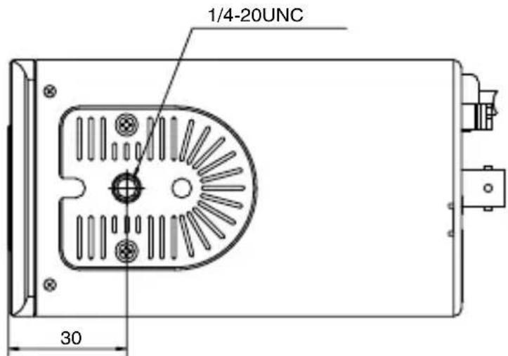
⑧Camera-mounting screw hole (1/4-20UNC)
Use this hole when mounting the camera onto a fixer, pan/tilt unit and the like. Use a screw shorter than 7 mm. (Pg. 23)
Note:
- Do not use a screw that is longer than the specified length. It may damage the internal parts.
⑨ Camera-mounting bracket
The bracket has been attached on the bottom of the camera before shipment. It can also be attached on the top according to the circumstance. (Pg. 24)
10 [BF LOCK] Back focus fastening screw
This serves to fix the back focus adjustment mechanism. (Pg. 26)
Name of Parts and their Functions (continued)
Back panel
TK-C925

TK-C926EG

⑪ [AC24V, DC12V] Power input terminal
To connect to AC 24 V or DC 12 V power supply.
(Pg. 21)
⑫ [AUX, GND] External terminals
This terminal is for the input/output signals that are set in the AUX MODE of the AUX FUNCTION screen. (Pg. 36)
●This terminal also outputs the B&W/Color signal. [Open-collector L signal. Maximum voltage 25 V, current 30 mA] - When switching B&W/Color using the control signal, the signals are input through this terminal. [B&W: MAKE, Color: BREAK]
⑬[VIDEO OUT] Video signal output connector
This connector outputs a composite video signal. Connect this to the video input connector of a video monitor, switcher and the like.
14[SELECTOR/SET] Selector switch/Set button
This allows user to select menu screens and change or confirm settings. (Pg. 32)
Press the SELECTOR switch up (▲) and hold for 1 second to set to [FOCUS ADJUST MODE] and open the lens iris for easy focusing. (As the depth of object field is lower, focus can be adjusted accurately.) (Pg. 26)
15[MENU] Menu button
When pressed, a menu screen is brought up. (Pg. 32)
16[INT,LL] Selector Switch for Synchronizing System
This switch sets the synchronizing system for the camera.
INT : This is set for internal synchronization (INT).
LL (Line Lock): This is set to synchronize the camera's vertical synchronization to the power frequency.
(Default setting: INT)
Name of Parts and their Functions (continued)
⑰ [POWER] Power indicator lamp
This lamp lights up when power is supplied to the camera.
18 Mounting Screw for Fall Prevention Wire
Use this screw when mounting the fall prevention wire to this unit. (Fall prevention wire is not supplied with this product.)
Note:
- Connect the fall prevention wire to prevent this unit from falling accidentally.
⑲ AC 230 V power cord
This connects the camera to a commercial AC 230 V socket.
Flow for Connection/Settings
Follow the procedures below to connect/set this unit.
Turn off the power of devices to be used before connecting the cables.
| step 1 | Mounting the lens (Pg. 18)Mount the lens. |
| ▼ | |
| step 2 | Connecting the back panel (Pg. 20)Connect the control signal cable, video signal coaxial cable and the like. |
| ▼ | |
| step 3 | Mounting the camera (Pg. 23)Mount the camera to the mounting location. |
| ▼ | |
| step 4 | Adjusting the back focus (Pg. 26)Adjust the back focus. |
| ▼ | |
| step 5 | Adjusting the lens (Pg. 28)Adjust the lens. |
| ▼ | |
| step 6 | Adjusting the auto white balance (Pg. 30) |
Mounting the lens

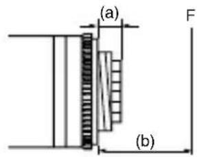


1. Check the mounting method of the lens before mounting
- This camera is set to CS-mount lens before shipment. To use a C-mount lens, loosen the back focus fastening screw with a screwdriver, turn the back focus adjustment ring with your finger or the screwdriver and change the mounting method.
- For the dimension (a) of the lens mounting section as illustrated in the diagram, use the value that is shown in the table below.
Note:
- Never use one that exceeds the dimension (a) as it will damage the inner part of the camera and will not allow normal installation. This will result in a malfunction.
| Lens Flange back (b) Dimension (a) | ||
| C-mount lens 17.5 | 26 mm | 5.5 mm or less |
| CS-mount lens 12.5 | mm | |
- Turn the lens clockwise and mount it securely on the camera.
- For an automatic iris control lens, select the switch on the side of this camera according to the lens used.
VIDEO : When using a lens with a built-in EE amplifier
DC : When using a lens without a built-in EE amplifier
- In the case of an automatic iris control lens, check the pin arrangement and connect the lens cable to the socket.
■4 pin plug
| Pin number | DC IRIS lens(Without built-in EE amplifier) | VIDEO IRIS lens(With built-in EE amplifier) |
| 1 Brake (-) 9.0 V (Max. 50 mA) | ||
| 2 | B r | a |
| 3 Drive (+) | VIDEO | |
| 4 | Drive (-) | GND |
k
Connecting the back panel
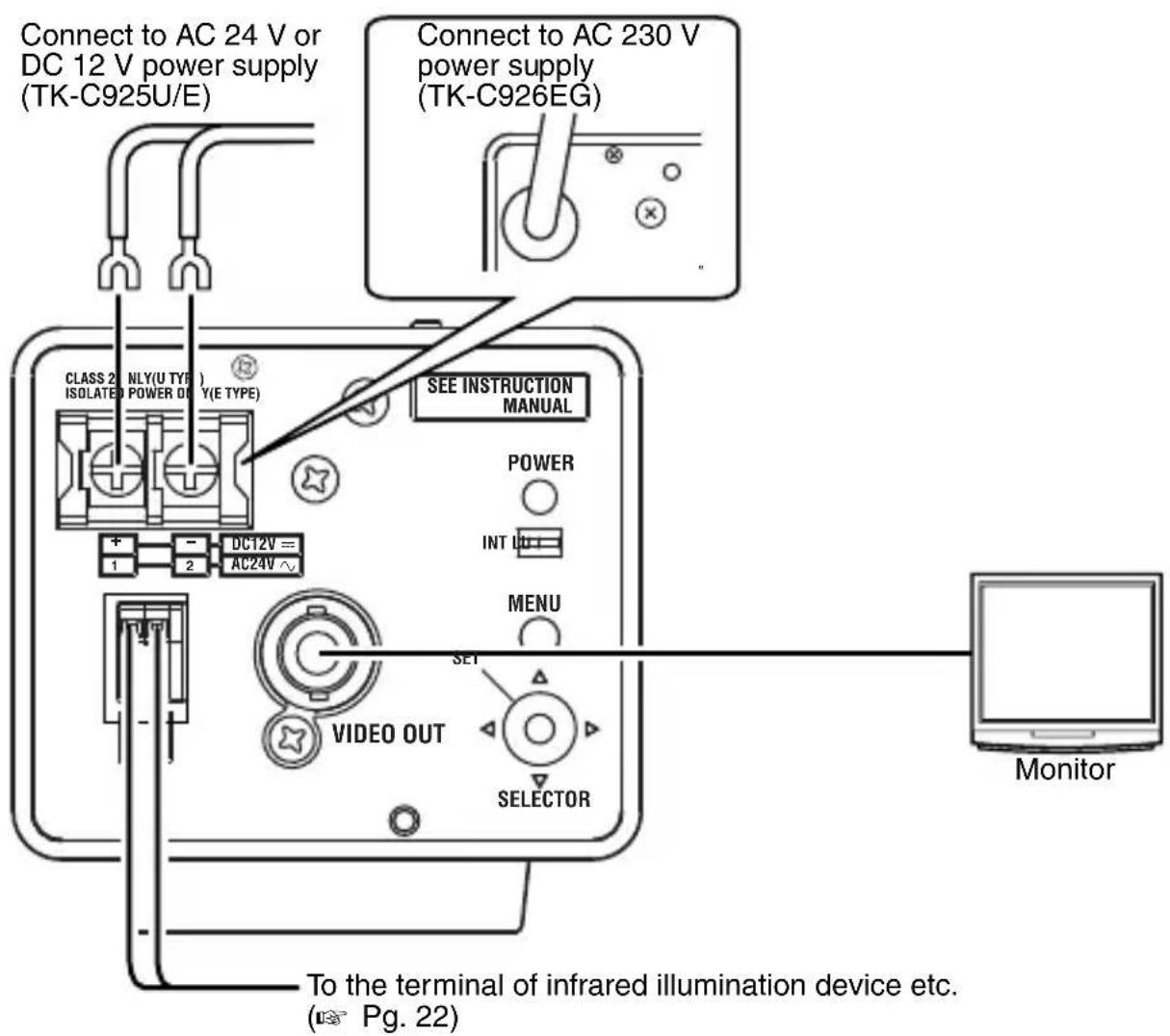
Memo:
●Turn off the power of devices to be used before connecting the cables. - Read through the "Instruction Manual" of the devices to be used carefully before connecting.
Connecting the power cable
■TK-C925 (AC24 V or DC12 V)
Connect the AC 24 V or the DC 12 V power cord to the power input terminal. To prevent connection errors or a cable disconnection, we recommend the use of lug plates.

The following table shows the connection distances when 2-core VVF (vinyl-insulated vinyl sheath cables) are used.
| Maximum connection distance | 60 m 150 m | 240 m 380 | m | |
| Conductor diameter 1.0 and more | more | 1.6 and more | 2.0 and more | 2.6 and more |
Note:
- If thin cables are used, the resistance of the cables will be high and a significant voltage drop will occur when the camera is at its maximum power consumption. Either use a thick cable with low resistance or place the power supply near to the camera and shorten the length of the cable to restrict the voltage drop at the rated current of camera to below 10%. If voltage drop occurs during operation, the performance will be unstable.
- Do not connect an AC 24 V cable to a commercial power supply. The camera will be damaged. If the wrong cable is connected, the internal circuit may be damaged. Do not use the camera. Bring it to your nearest JVC dealer for inspection.
■TK-C926EG (AC 230 V)
Connect the power supply cable to the AC 230 V power supply.
Note:
- When you use this camera, the socket-outlet must be installed near the equipment to make disconnection easy.
Video signal coaxial cable
Use either RG-59 or RG-11 coaxial cable (BNC).
Do not use other cables.
Connecting the back panel (continued)
Connecting alarm input/output terminal
■Alarm input terminal
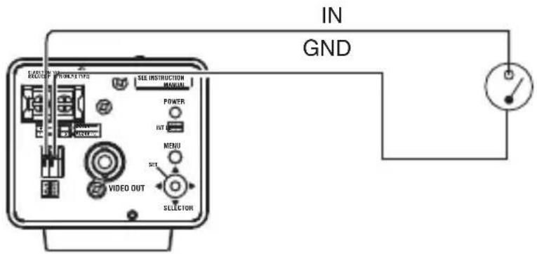
Connect infrared sensor, door sensor, metal sensor or sensor of manual switch and the like.
●To prevent noise from entering the internal circuit, supply a non-voltage setting signal. - Do not supply voltage. - Can be set via menu whether to set to alarm when the contact is short (MAKE), or when the contact is open (BREAK). (Pg. 37) ●Supply such that the alarm signal continues for more than 200 ms. The recognition of alarm signal may not be guaranteed if less than 200 ms.
Alarm output terminal
Connect to alarm devices such as alarm, indicator, light or buzzer.
- As it is an open type collector output insulated by photocoupler, it will turn on during alarm.
- This terminal has polarity. Make sure to connect such as the voltage of + terminal is higher than - terminal. It will be damaged if reverse voltage is supplied.

Mounting the camera
When mounting the camera on a fixer, pan/tilt and the like, use the camera-mounting screw hole located on the camera-mounting bracket.
Camera-mounting screw hole
Camera-mounting bracket fixing screws (x2: M2.6 x 6 mm)


Note:
- Use a camera-mounting screw with a length shorter than 7 mm from the camera-mounting face. Do not use a screw that is longer than the specified length. It may damage the internal parts.
Mounting the camera (continued)
Mounting the camera-mounting bracket on top of the camera
The camera-mounting bracket is originally mounted at the bottom of the camera before shipment but it can also be mounted on top of the camera.

- Remove the camera-mounting bracket fastening screws (x2). The camera-mounting bracket is removed from the camera.
- Mounting the camera-mounting bracket on top of the camera
- Mounting the camera onto a fixer, pan/tilt unit and the like
Note:
- Use a camera-mounting screw with a length shorter than 7 mm from the camera-mounting face. Do not use a screw that is longer than the specified length. It may damage the internal parts. ●To mount the camera-mounting bracket on top of the camera, use the screw holes on the back panel.
Fall Prevention
Use the black mounting screw on the back of the camera to install the fall prevention wire

Precautions regarding fall prevention
●Special attention is required when installing the camera to the wall or ceiling. You should not engage in the installation work yourself. Ask a professional to do the job, since the fall of the camera can result in injuries and accidents. - When installing the camera on a fixer, pan/tilt unit and the like, make sure to install it firmly using a rotation-preventive hole to prevent fall. ●To prevent fall, connect the camera to a section with sufficient strength (ceiling slab or channel) using a fall prevention wire. ●Pay attention to the length, strength, routing and material (insulation properties) of the fall prevention wire used. - Use the black screw (M3 x 6 mm) on the back of the camera for the installation of the fall prevention wire. Using other screws of different sizes may damage the inside.
Adjusting the back focus
This camera is adjusted to a optimum wide range for CS-mount lens before shipment but readjustment is required when using zoom lens or C-mount lens or when the lens focus ring is out of focus. Use the following methods to adjust the back focus.
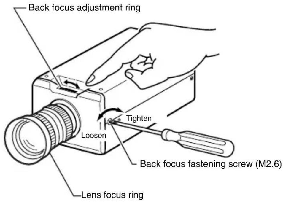
With a fixed-focus lens
If the focus cannot be adjusted correctly with the lens focus ring, adjust the back focus as follows.
- Loosen the back focus fastening screw by turning it anti-clockwise with a + screwdriver.
- Shooting an object or a picture with fine patterns that is away from the object
- Turn the lens focus ring to∞.
- Turn the back focus adjustment ring to focus at the best point.
- Tighten the back focus fastening screw by turning it clockwise.
With a zoom lens
If the image is out of focus when zooming (telephoto - wide angle), adjust the camera as follows.
- Loosen the back focus fastening screw by turning it anti-clockwise with a + screwdriver.
- Shooting an object or a picture with fine patterns that is away from the object
- Zoom to the maximum telephoto position and turn the lens focus ring to adjust the focus.
- Zoom to the maximum wide angle position and turn the back focus adjustment ring to adjust the focus.
- Repeat steps 3 and 4 two or three times.
- Tighten the back focus fastening screw by turning it clockwise.
Note:
- In the case of B&W/Color mode, the lens performance may cause the image to be out of focus when the illumination of the object is near-infrared light. In such a case, use a lens that is compatible with near-infrared light.
Memo:
- Focus setting may differ on the color and on the black and white screen. Make adjustments so that the focus will come to the optimum on both screens.
Adjusting the lens
After the connection is complete, turn on the camera, display an image on the monitor, and check the video image.
In the case of an automatic iris control lens, the camera has been factory-adjusted to the best position, but it may need to be adjusted according to the condition of the object or the lens combination. If the image is unnatural, adjust it.
●Also read the instruction manual of the lens.
■With a VIDEO automatic iris lens (Automatic iris control lens with built-in EE amplifier)
Set the switch at the side of the camera to "VIDEO" and adjust the LEVEL dial on the lens.
LEVEL adjustment

■With a DC automatic iris lens (Automatic iris control lens without built-in EE amplifier)
Set the Iris Selector Switch at the side of the camera to "DC" and adjust the LEVEL with the Iris Level Adjustment Dial at the side of the camera.

●LEVEL adjustment
| Monitor screen LEVEL adjustment direction | |
| To darken Anti-clockwise (Towards L) | |
| To brighten Clockwise (Towards H) |
Memo:
- If the LEVEL sensitivity adjustment is turned excessively to L, the sensitivity increases because of the AGC function of the camera and the image looks grainy.
- Depending on the lens used, if the LEVEL dial is turned excessively to L, the hunting phenomenon (floppy screen) where the iris opens and closes involuntarily may occur. In such a case, first set the LEVEL dial to the H position, and then readjust the LEVEL dial while checking the video signal.
- To adjust the focus accurately, open the lens iris. Below is how to open the lens iris for automatic iris lens.
- Press the [SELECTOR] switch on the back panel up (▲) for 1 second. [FOCUS ADJUST MODE] is displayed on the monitor screen.
- When the focus adjustment is completed, press either [SELECTOR] switch (▲, ▼, ◀, ▼), [MENU] or [SET] button. [FOCUS ADJUST MODE] display disappears and the lens iris returns to original state.
- Connect the monitor TV to the VIDEO OUT terminal on the back panel and make adjustments.
Adjusting the auto white balance
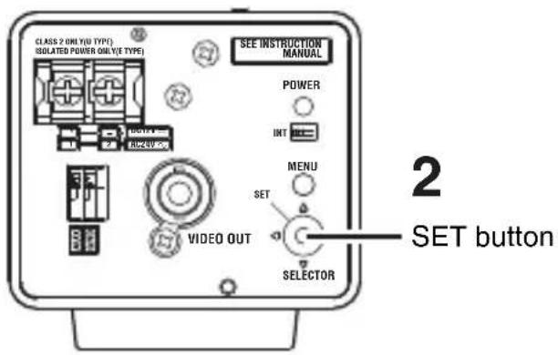
Each light source has its own color temperature. Therefore, when the main light source lighting an object is changed, press the SET button for a while and adjust the white balance again.
3![graph LR A["AWC OPERATION"] --> B["AWC OK"]](/content/2026/06/1260099/images/a44342734bfae9a4df2fbc29ac97433b54a1c430903307265368b3ac4f741d7b.jpg)
■Error display
Excessive Illumination
- Place a white object at the center of the screen, under the same lighting condition as the object to be shot and zoom in to fill the screen with white.
- Press the SET button for approx. one second.
Auto white balance adjustment begins. During operation, “AWC OPERATION” is displayed on the screen.
- Adjustment is complete.
When the appropriate white balance is acquired, “AWC OK” is displayed.
■Error display
When auto white balance adjustment is not successful, the following messages will be blinking on the monitor.
AWC ERROR : NG OBJECT (Object error)
Displayed when there is not enough white color on an object or the color temperature is not suitable.
Shoot a white object to fill the screen thoroughly and adjust the white balance again.
AWC ERROR : LOW LIGHT (Insufficient Illumination)
Displayed when the light is low. Increase the illumination, then readjust the white balance.
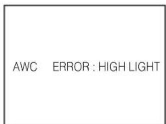
AWC ERROR : HIGH LIGHT (Excessive Illumination)
Displayed when the light is too bright. Decrease the illumination, then readjust the white balance.
Menu basic operation
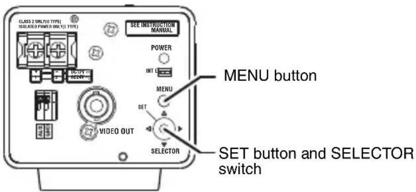
1. Press the MENU button
The MENU screen is displayed.
2. Press the SELECTOR switch up and down (▲, ▼) to set the cursor (▷) to a desired menu.
Cursor
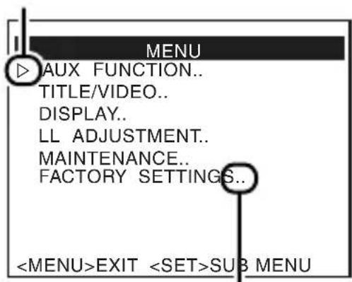
Sub-menu
(indicated by ... at the end.)
3. Press the SET button
The selected sub-menu screen is displayed.
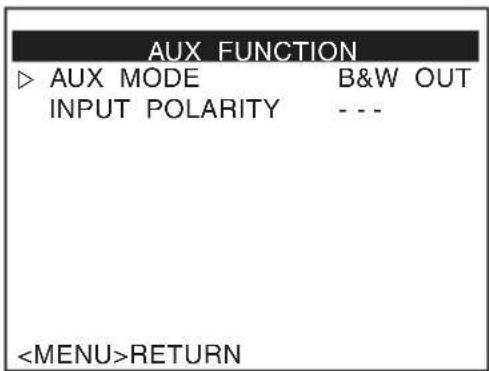
4. Press the SELECTOR switch up and down (▲, ▼) to set the cursor (▷) to a desired item.

- Press the SELECTOR switch left or right (◀, ▶) to change the setting. When a setting has been changed, a change mark (*) is displayed. The change mark (*) disappears when the changed setting is saved.
Change mark (*)

Memo:
- To change the settings of multiple items, repeat steps 4., 5..
6. Press the MENU button.
The screen returns to the previous one (MENU screen).
7. Press the MENU button again.
The screen returns to the normal screen (without the menu display).
The flow of menu screen![graph TD A["MAIN MENU"] --> B["AUX FUNCTION"] B --> C["AUX MODE INPUT POLARITY"] A --> D["TITLE/VIDEO"] D --> E["CAMERA TITLE EDIT"] E --> F["W.BALANCE"] F --> G["W.BALANCE ADJUST"] G --> H["When "AWC" is selected"] H --> I["AWC EXECUTE"] H --> J["AWC SET R GAIN B G A I N"] E --> K["SHUTTE…](/content/2026/06/1260099/images/8ec0c8c9e107c72d5d8f8e2cb76c940a1862f7e25e1b691b518cde8705d4101d.jpg)
![graph TD A["DISPLAY"] --> B["(Pg. 45)"] A --> C["MONITORTYPE"] D["LLADJUSTMENT"] --> E["(Pg. 46)"] D --> F["V.PHASE"] G["MAINTENANCE"] --> H["(Pg. 46)"] G --> I["CCDSpotSCANCANCEL EXECUTE"] J["FACTORYSETTINGS"] --> K["(Pg. 47)"] J --> L["CANCEL CLEAR(WITHOUTTITLE) CLEAR(ALL)"]](/content/2026/06/1260099/images/f941d158aad61b0e64d1d594d8823236ef5e2cf965b62ea4793955bd245272ee.jpg)
AUX FUNCTION screen
| Item Functions and settings | |
| AUX MODE This item sets the signal input or output of the AUX terminal.B&W OUT: A signal is output when the camera switches to B&W or Color mode.IR IN: Depending on the input signal of the AUX terminal, the camera can switch between B&W and Color mode. When there is an alarm input, the mode will be B&W.※When the INPUT POLARITY item of the AUX FUNCTION is “MAKE”When the contact is short (MAKE), the mode is B&W.When the contact is open (BREAK), the mode is Color.※When the INPUT POLARITY item of the AUX FUNCTION is “BREAK”.When the contact is open (BREAK), the mode is B&W.When the contact is short (MAKE), the mode is Color.[Setting: IR IN, B&W OUT][Default setting: B&W OUT] | |
| INPUT POLARITY | This sets the polarity of the AUX input signal.MAKE: When the contact between all alarm input terminals and GND terminals changes from open to close, the alarm will activate.BREAK: When the contact between all alarm input terminals and GND terminals changes from close to open, the alarm will activate.[Setting: MAKE, BREAK][Default setting: MAKE]Memo:When AUX MODE item is set to “B&W OUT”, “- - -” will be displayed and settings is disabled. |
TITLE/VIDEO screen
| Item Functions and settings | |
| CAMERA TITLE EDIT | This item sets the title to be displayed permanently on the lower part of screen. A maximum of 24 characters can be set for the title.“Camera title setting” (Pg. 48) |
| W.BALANCE This item sets the white balance function.Select “ATW” when adjusting the white balance according to the changes of the object, and select “AWC” when shooting using adjusted white balance.Memo:In B&W mode, “- - - ” will be displayed and settings is disabled. | |
| ATW This is the Auto-Tracking White Balance mode.(Automatic color temperature tracking.) The camera adjusts the white balance automatically according to the color temperature of the illumination. | |
| ATW(WI DE) | This mode supports an even wider range of color temperature than ATW. Use this mode when white balance cannot be achieved under a light source such as high pressure sodium lamp. |
TITLE/VIDEO screen (continued)
| Item Functions and settings | ||
| W.BALANCE (continued) | ||
| AWC AWC | SET:The Auto White Control (automatic white balance adjustment) mode adjusts the white balance automatically. | |
| Display during AWC operationMeaning of display | ||
| AWC OPERATION AWC in operation | ||
| AWC OK AWC completed normally | ||
| AWC ERROR : NG OBJECT AWC completed outside range | ||
| AWC ERROR : HIGH LIGHT AWC completed with overlighting | ||
| AWC ERROR : LOW LIGHT AWC completed with low lighting | ||
| R GAIN: Adjusts the R(red) hue during AWC. The larger the number, the redder the color becomes.[Setting:0 to 255]B GAIN: Adjusts the B(blue) hue during AWC. The larger the number, the bluer the color becomes.[Setting:0 to 255] | ||
| SHUTTER This item sets the electronic shutter. | ||
| MODE | Select the mode of the electronic shutter.MANUAL: This operates in the shutter speed set in the MANUAL SPEED item.AUTO: This automatically switches the shutter speed according to brightness. The fastest value of a shutter speed is set in the AUTO LIMIT item (Pg. 39).[Default setting: MANUAL] | |
| Item Functions and settings | |
| SHUTTER (continued) | |
| MANUAL SPEED | This sets a shutter speed when MANUAL is set.TK-C925U[Setting: NORMAL, 1/100, 1/250, 1/500, 1/1000, 1/2000, 1/4000, 1/10000][Default setting: NORMAL]TK-C925E/TK-C926EG[Setting: NORMAL, 1/120, 1/250, 1/500, 1/1000, 1/2000, 1/4000, 1/10000][Default setting: NORMAL]Memo:When SHUTTER item is set to “AUTO”, “- - -” will be displayed and settings is disabled. |
| AUTO LIMIT | This sets the fastest value of a shutter speed when AUTO is set.TK-C925U[Setting: 1/100, 1/250, 1/500, 1/1000, 1/2000, 1/4000, 1/10000, 1/20000, 1/40000, 1/100000][Default setting:1/100000]TK-C925E/TK-C926EG[Setting: 1/120, 1/250, 1/500, 1/1000, 1/2000, 1/4000, 1/10000, 1/20000, 1/40000, 1/100000][Default setting:1/100000]Memo:When SHUTTER item is set to “MANUAL”, “- - -” will be displayed and settings is disabled.The higher the shutter speed becomes, the more smear phenomenon is emphasized, which is peculiar to the CCD. |
| GAIN This item sets the gain. | |
| MODE Select the gain adjustment mode. Sensitivity increases electronically for an object with low illumination.AGC (Automatic Gain Control): This automatically adjusts the electronic gain according to the illumination of the object.FIXED (Fixed gain): This operates in the gain set in the FIX GAIN item regardless of the illumination of the object.[Default setting: AGC] | |
| GAIN (continued) | |
| MAX GAIN | This item sets a maximum gain of the AGC (Automatic Gain Control).0(OFF): No AGC function.HIGH: Increase the gain up to a maximum of 26dB according to the illumination of an object.SUPER: Increase the gain up to a maximum of 32dB according to the illumination of an object.[Default setting: HIGH]Memo:When the MODE item of B&W/COLOR is set to “AUTO”, the MODE item becomes “AGC” [(AGC) is displayed] but “HIGH/SUPER” can be selected.When it is set to “0(OFF)”, “HIGH” will be selected automatically.When MODE item is set to “FIXED”, “- - - ” will be displayed and settings is disabled. |
| FIX GAIN | This sets the value of fixed gain when MODE is set to “FIXED”.[Setting: 0 to 20][Default setting: 10]Memo:When MODE item is set to “AGC”, “- - - ” will be displayed and settings is disabled. |
TITLE/VIDEO screen (continued)
"COLOR" display differs depending on the model.
“COLOR” is displayed for TK-C925U and “COLOUR” is displayed for
TK-C925E/TK-C926EG.
From this point onwards, "COLOR" will be used for indication.
| Item Functions and settings | |
| B&W/COLOR (TK-C925U)B&W/COLOUR (TK-C925E/TK-C926EG) | This item sets the mode switching of B&W and Color. Memo:●When switching the Color mode to B&W mode, the type of light source may cause the focus to be dislocated. This is because the B&W mode is sensitive to both visible light and near-infrared light. When this happens, adjust the focus again in B&W mode.●Use infrared illumination if necessary. |
| MODE This | sets the function to switch from Color to B&W mode. The options change according to the setting of AUX MODE item in AUX FUNCTION (Pg. 36). |
| AUX MODE setting MODE options | |
| IR IN (AUX IN) | |
| B&W OUT COLOR,B&W,AUTO | |
| COLOR: Sets the camera permanently to Color mode. B&W: Sets the camera permanently to B&W mode. AUTO: The camera automatically switches to Color mode when the object is bright and B&W mode when it is dark. | |
| Item Functions and settings | |||||
| B&W/COLOR (continued) | |||||
| MODE(continued) | [Default setting: COLOR]*Display for TK-C925U. For TK-C925E/TK-C926EG, COLOUR is displayed.Memo:To ensure a successful B&W/Color switchingIf the MODE item of B&W/COLOR is set to “AUTO”, the B&W/Color setting can be switched according to the brightness of the object, but the condition of illumination and field angle may make this impossible. To be absolutely certain of B&W/Color switching, we recommend you to input signals of an external sensor (available separately) to the [AUX,GND] external terminal of this camera before switching. (Pg. 54) | ||||
| AUTO LEVEL | When the MODE item is set to “AUTO”, this function sets the signal level of the object where the camera will switch to B&W mode.LOW: Switches to B&W mode when the signal level of the object indicates low illumination.NORMAL: Switches to B&W mode when the signal level of the object indicates normal illumination.HIGH: Switches to B&W mode when the signal level of the object indicates high illumination.[Default setting: NORMAL]*Display for TK-C925U. For TK-C925E/TK-C926EG, COLOUR is displayed.Memo:● When MODE item of B&W/COLOR is set to “AUTO”, “- - -” will be displayed and settings is disabled. | ||||
| AUTO TIME | When the MODE item is set to “AUTO”, this function sets the time required to switch to the B&W/Color mode.Example:When set to 30s, the camera will switch to B&W mode 30 seconds after it has become dark.[Setting: 10s,20s,30s][Default setting: 30s]Memo:● When MODE item of B&W/COLOR is set to “AUTO”, “- - -” will be displayed and settings is disabled. | ||||
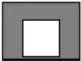
| BLC MODE | Sets the backlight compensation function. Set this item when there is a bright light source in the background of the object and the object becomes dark in the automatic iris function. Set such that unnecessary light source is outside the photometry area.OFF: No backlight compensation.AREA1 to AREA4: Refer to the diagram below to set the item.[Default setting: OFF] | ||||
 |  |  |  |  | |
| OFFAREA1AREA2AREA3AREA4 | 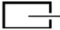 | Photometry area | |||
DISPLAY screen
| Item Functions and settings | |
| MONITOR TYPE | This sets the monitor type.You can change the output video settings according to the type of monitor used. Select an appropriate mode.[Setting: CRT,LCD1,LCD2][Default setting: CRT] |
LL ADJUSTMENT screen
| Item Functions and settings | |
| V.PHASE This adjusts the vertical synchronization to those of other cameras when a selector switch for the synchronizing system on the back of the camera is at “LL”.TK-C925UThis item can only operate in a region with a power frequency of 60 Hz.[Setting: -131 to 0 to 131][Default setting: 0]TK-C925E/TK-C926EGThis item can only operate in a region with a power frequency of 50 Hz.[Setting: -156 to 0 to 156][Default setting: 0]Memo:● When set to “INT”, “- - -” will be displayed and settings is disabled. |
MAINTENANCE screen
White spots may appear on the screen due to changes in properties with time. This is a general characteristic of CCDs. This camera has a built-in white spot compensation function to reduce these white spots.
| Item Functions and settings | |
| CCD SPOT SCAN | CANCEL: No white spot compensation. The screen returns to the main menu.EXECUTE: Starts CCD spot detection.Memo:The white spot compensation function of this camera does not completely compensate white spots.Maximum number of compensation is 32.White spots may not be compensated due to its properties.As white spot compensation is interpolated from the surrounding pixels, the camera may not acquire accurate image information when the object has very fine pattern.The result of white spot compensation is maintained until the next compensation. |
FACTORY SETTING screen
The values set on the menu are returned to the default settings.
| Item Functions and settings | |
| CANCEL Does not return to the default setting. The screen returns to the main menu. | |
| CLEAR(WITH OUT TITLE) | Returns settings except titles to the default setting.Memo:●Once default setting is returned, the screen automatically returns to the main menu. |
| CLEAR(ALL) Returns all settings including titles to the default setting.Memo:●Once default setting is returned, the screen automatically returns to the main menu. | |
Camera title setting
A title can be selected for each camera. (Maximum 24 characters)

1. Select the item CAMERA TITLE EDIT on the TITLE/VIDEO screen and press the SET button.
The CAMERA TITLE EDIT screen is displayed.
The first character from the character area flashes on and off and is ready for input.

TITLE/VIDEO screen
![Space Character area Flashing 0123456789 ABCDEFGHIJKLMNO PQRSTUVWXYZ abcdefghijklono pqrstuvwxyz AÖÜEİÖÜÇNäelõu äölõüäelõüäelõüçnßiL . , '- : / () <> CLR CANCEL [—] [—] INS DEL RETURN CHAR. SET CAMERA TITLE EDIT screen Input frame Title input area Only displayed in TK-C925E/TK-C926EG](/content/2026/06/1260099/images/a94fcba80174fa164d0bdd2cd33124053d56958605bde3e5dead5fb7189ab831.jpg)
- Press the SELECTOR switch up, down, left or right (▲, ▼, ◀, ►) and select a character from the character area.
The selected character is displayed flashing on and off.
- Press the SET button.
The first character is confirmed and the blinking title input area moves to the second character.
- Repeat steps 2 to 3.
It is possible to use up to 24 characters to input the camera title.
- Press the MENU button.
The new camera title is saved and the top menu (TITLE/VIDEO screen) is displayed.
To set multiple camera titles, repeat steps 1 to 5.
How to operate
| Menu operation State | |
| CLR+SET Clears all | entered text. |
| CANCEL+SET Cancels the edited setting and returns to the previous state. | |
| [←]+SET Moves the | input frame of the title input area one step to the left. |
| [→]+SET Moves the | input frame of the title input area one step to the right. |
| INS+SET Inserts one | space and moves subsequent characters to the right. |
| DEL+SET Deletes the character selected by the cursor and moves subsequent characters one step to the left. | |
Manual adjustment of white balance
When automatic adjustment of the white balance results in a “reddish screen”, adjust the white balance manually.

1. Set the W.BALANCE item on the TITLE/VIDEO screen to "AWC" and press the SET button.
The W.BALANCE ADJUST screen is displayed.

TITLE/VIDEO screen

W.BALANCE ADJUST screen
- Press the SELECTOR switch up or down (▲, ▼) and select the hue to be adjusted (R GAIN or B GAIN).
- Press the SELECTOR switch left or right (◀, ▶) to change the setting.
R GAIN: Adjusts the R (red) hue during AWC. The larger the number, the redder the color becomes.
[Setting 0 to 255]
B GAIN: Adjusts the B (blue) hue during AWC. The larger the number, the bluer the color becomes.
[Setting 0 to 255]
- Press the MENU button.
After the adjustment, press the MENU button to return to the TITLE/VIDEO screen.
Memo:
- When adjusting the hue, the screen will return to the TITLE/VIDEO screen if the mode is switched from Color to B&W. When this happens, any adjusted values will not be saved.
Output of B&W/Color switching signal
It is possible to output B&W/Color switching signal from the AUX terminal on the back of this camera.
B&W/Color switching signal is output by setting both the AUX MODE and B&W/COLOR items.
■ Set the AUX MODE item to "B&W OUT"
- Select the item AUX FUNCTION on the main menu screen and press the SET button.
The AUX FUNCTION screen is displayed.
- Press the SELECTOR switch up or down (▲, ▼) and select AUX MODE.
- Press the SELECTOR switch left or right (◀, ▶) and set to B&W OUT.

Main menu screen

AUX FUNCTION screen
4. Press the MENU button twice.
The setting is complete and the screen returns to the normal screen.
■ Set the B&W/COLOR item to AUTO
- Select the item B&W/COLOR on the TITLE/VIDEO screen and press the SET button. The B&W/COLOR screen is displayed.
- Press the SELECTOR switch up or down (▲, ▼) and select MODE.
- Press the SELECTOR switch left or right (◀, ▶) and set to AUTO.

TITLE/VIDEO screen

B&W/COLOR screen


4. Press the MENU button twice.
The setting is complete and the screen returns to the main menu.
Memo:
- When near-infrared illumination is used, a B&W screen may switch to a color screen if the object reflects light excessively. To perform switching with higher accuracy, we recommend that you use the settings mentioned in “Control by B&W/Color switching signal from external” (Pg. 54).
- In the case of B&W/Color mode, the lens performance may cause the image to be out of focus when the illumination of the object is near-infrared light. In this case, use a lens that is compatible with near-infrared light.
Control by B&W/Color switching signal from external
You can use the switching signal from an external control device to link the B&W/Color switching or near-infrared illumination of this camera.
Consult your nearby JVC's dealer on the connecting devices.
Example)
AUX MODE : IR IN
INPUT POLARITY : In the case of MAKE (Pg. 36)
![graph TD A["Infrared illumination"] --> B["External control device"] B --> C["Sensor or switch"] C --> D["B&W : MAKE signal\nColor : BREAK signal"] D --> E["SEE INSTRUCTION MANUAL"] E --> F["POWER"] E --> G["INT LED"] E --> H["MENU"] E --> I["SET"] E --> J["VIDEO OUT"] E --> K["SELECTOR"]](/content/2026/06/1260099/images/4504d7066e81a9471d69ecce50149491621b7a326030751d1b447526148dbbea.jpg)

■When performing only B&W/Color mode switching without changing other video settings
- Select the item AUX MODE on the AUX FUNCTION screen.
- Press the SELECTOR switch left or right (◀,▶) and set to "IR IN".
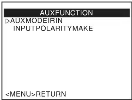
AUX FUNCTION screen
Memo:
- In the case of B&W/Color mode, the lens performance may cause the image to be out of focus when the illumination of the object is near-infrared light. In this case, use a lens that is compatible with near-infrared light.
Specifications
Camera
Signaling method
TK-C925U : NTSC
TK-C925E/TK-C926EG
: PAL
Image pickup device
: 1/3 type IT CCD
Color imaging method
: Single color-difference line sequential system, 2:1 interlace
Imaging area
: 4.8 mm (H) × 3.6 mm (V), (diagonal 6 mm)
Scanning frequency
TK-C925U : 15.734 kHz (horizontal), 59.94 Hz (vertical)
TK-C925E/TK-C926EG
: 15.625 kHz (horizontal), 50 Hz (vertical)
Effective pixels
TK-C925U : 380,000 pixels, 768 (H) x 494 (V)
TK-C925E/TK-C926EG
: 440,000 pixels, 752 (H) x 582 (V)
Synchronization method
: Internal (INT)/Power synchronization (LL)
Video S/N ratio
: 50 dB (Standard, AGC OFF, White 50 % output)
Horizontal resolution
: 540 TV lines (standard)
Video output
Minimum brightness of object
Color mode : 1.5 lx (F1.2, AGC ON, 50 % output)
B&W mode : 0.08 lx (F1.2, AGC ON, 50 % output) (Calculated value)
Lens
Lens Mount
: C/CS mount
General
Power supply
TK-C925U : AC 24 V 60 Hz, DC 12 V
TK-C925E : AC 24 V 50 Hz, DC 12 V
TK-C926EG : AC230 V 50 Hz
Power consumption
TK-C925U : 4.8 W
TK-C925E : 400 mA
TK-C926EG : 75 mA
Ambient temperature
Operation : -10 °C to 50 °C (14 °F to 122 °F)
Recommended : 0 °C to 40 °C (32 °F to 104 °F)
Humidity
:
Mass
TK-C925U/E : Approx. 480 g
TK-C926EG : Approx. 700 g
Accessories
TK-C925U : Instructions .... 1
Warranty Card.... 1
Service Information Card 1
TK-C925E/TK-C926EG
: Instructions .... 1
Specifications (continued)
■Dimensions [Unit: mm (inch)]
TK-C925U/E![JVC TK-C925E - ■Dimensions [Unit: mm (inch)] - 1](/content/2026/06/1260099/images/32bf1b7fb6e74b7f01c5b6149bae1d06aea3eea56274c0d04dae8d6571153a06.jpg)
TK-C926EG


* Specifications and appearance of this camera and related products are subject to change for improvements without notice.
TK-C925U/E, TK-C926EG COLOR VIDEO CAMERA
JVC


- FOR CUSTOMER USE
- FOR USA
- IMPORTANT SAFEGUARDS
- SAFETY PRECAUTIONS
- FOR USA AND CANADA
- CAUTION
- WARNING
- AVERTISSEMENT
- INFORMATION (FOR CANADA)
- INFORMATION FOR USA
- INFORMATION
- SAFETY PRECAUTIONS (CONTINUED)
- ATTENTION
- INFORMATION FOR USERS ON DISPOSAL OF OLD EQUIPMENT
- [EUROPEAN UNION]
- (BUSINESS USERS)
- [OTHER COUNTRIES OUTSIDE THE EUROPEAN UNION]
- FEATURES
- REALIZING A HIGH PICTURE QUALITY
- DAY/NIGHT SURVEILLANCE
- CRT/LCD MONITOR COMPATIBLE
- REALIZING SHARPER VIDEO IMAGES
- HOW TO READ THIS MANUAL
- CONVENTIONS AND SYMBOLS
- CONTENTS
- INTRODUCTION
- SETUP
- SETTING
- DETAILED SETTING
- OTHERS
- OPERATING PRECAUTIONS
- STORAGE AND LOCATION OF USE
- MAINTENANCE
- ENERGY CONSERVATION
- NAME OF PARTS AND THEIR FUNCTIONS
- FRONT/BOTTOM/SIDE PANEL
- ① BACK FOCUS ADJUSTMENT RING
- ② LENS MOUNT
- ③ CAMERA-MOUNTING BRACKET FIXING SCREWS (X2: M2.6 X 6 MM)
- NOTE
- ④[IRIS] IRIS TERMINAL
- ⑤[VIDEO,DC] IRIS SELECTOR SWITCH
- ⑥[LEVEL] IRIS LEVEL ADJUSTMENT DIAL
- ⑦ROTATION-PREVENTIVE HOLE
- ⑧CAMERA-MOUNTING SCREW HOLE (1/4-20UNC)
- ⑨ CAMERA-MOUNTING BRACKET
- [BF LOCK] BACK FOCUS FASTENING SCREW
- NAME OF PARTS AND THEIR FUNCTIONS (CONTINUED)
- BACK PANEL
- TK-C
- TK-C926EG
- ⑪ [AC24V, DC12V] POWER INPUT TERMINAL
- ⑫ [AUX, GND] EXTERNAL TERMINALS
- ⑬[VIDEO OUT] VIDEO SIGNAL OUTPUT CONNECTOR
- [SELECTOR/SET] SELECTOR SWITCH/SET BUTTON
- [MENU] MENU BUTTON
- [INT,LL] SELECTOR SWITCH FOR SYNCHRONIZING SYSTEM
- ⑰ [POWER] POWER INDICATOR LAMP
- MOUNTING SCREW FOR FALL PREVENTION WIRE
- ⑲ AC 230 V POWER CORD
- FLOW FOR CONNECTION/SETTINGS
- MOUNTING THE LENS
- CHECK THE MOUNTING METHOD OF THE LENS BEFORE MOUNTING
- PIN PLUG
- CONNECTING THE BACK PANEL
- MEMO
- CONNECTING THE POWER CABLE
- TK-C925 (AC24 V OR DC12 V)
- TK-C926EG (AC 230 V)
- VIDEO SIGNAL COAXIAL CABLE
- CONNECTING THE BACK PANEL (CONTINUED)
- CONNECTING ALARM INPUT/OUTPUT TERMINAL
- ALARM INPUT TERMINAL
- ALARM OUTPUT TERMINAL
- MOUNTING THE CAMERA
- MOUNTING THE CAMERA (CONTINUED)
- MOUNTING THE CAMERA-MOUNTING BRACKET ON TOP OF THE CAMERA
- FALL PREVENTION
- PRECAUTIONS REGARDING FALL PREVENTION
- ADJUSTING THE BACK FOCUS
- WITH A FIXED-FOCUS LENS
- WITH A ZOOM LENS
- ADJUSTING THE LENS
- WITH A VIDEO AUTOMATIC IRIS LENS (AUTOMATIC IRIS CONTROL LENS WITH BUILT-IN EE AMPLIFIER)
- WITH A DC AUTOMATIC IRIS LENS (AUTOMATIC IRIS CONTROL LENS WITHOUT BUILT-IN EE AMPLIFIER)
- ●LEVEL ADJUSTMENT
- ADJUSTING THE AUTO WHITE BALANCE
- ERROR DISPLAY
- AWC ERROR : NG OBJECT (OBJECT ERROR)
- AWC ERROR : LOW LIGHT (INSUFFICIENT ILLUMINATION)
- AWC ERROR : HIGH LIGHT (EXCESSIVE ILLUMINATION)
- MENU BASIC OPERATION
- PRESS THE MENU BUTTON
- PRESS THE SELECTOR SWITCH UP AND DOWN (▲, ▼) TO SET THE CURSOR (▷) TO A DESIRED MENU
- PRESS THE SET BUTTON
- PRESS THE SELECTOR SWITCH UP AND DOWN (▲, ▼) TO SET THE CURSOR (▷) TO A DESIRED ITEM
- PRESS THE MENU BUTTON AGAIN
- TITLE/VIDEO SCREEN
- TITLE/VIDEO SCREEN (CONTINUED)
- DISPLAY SCREEN
- LL ADJUSTMENT SCREEN
- MAINTENANCE SCREEN
- FACTORY SETTING SCREEN
- CAMERA TITLE SETTING
- SELECT THE ITEM CAMERA TITLE EDIT ON THE TITLE/VIDEO SCREEN AND PRESS THE SET BUTTON
- MANUAL ADJUSTMENT OF WHITE BALANCE
- SET THE W.BALANCE ITEM ON THE TITLE/VIDEO SCREEN TO "AWC" AND PRESS THE SET BUTTON
- OUTPUT OF B&W/COLOR SWITCHING SIGNAL
- SET THE AUX MODE ITEM TO "B&W OUT
- PRESS THE MENU BUTTON TWICE
- SET THE B&W/COLOR ITEM TO AUTO
- CONTROL BY B&W/COLOR SWITCHING SIGNAL FROM EXTERNAL
- SPECIFICATIONS
- CAMERA
- SIGNALING METHOD
- IMAGE PICKUP DEVICE
- IMAGING AREA
- SCANNING FREQUENCY
- EFFECTIVE PIXELS
- SYNCHRONIZATION METHOD
- VIDEO S/N RATIO
- HORIZONTAL RESOLUTION
- VIDEO OUTPUT
- MINIMUM BRIGHTNESS OF OBJECT
- LENS
- GENERAL
- POWER SUPPLY
- POWER CONSUMPTION
- AMBIENT TEMPERATURE
- HUMIDITY
- MASS
- ACCESSORIES
- SPECIFICATIONS (CONTINUED)
- DIMENSIONS [UNIT: MM (INCH)]
- JVC
Brand : JVC
Model : TK-C925E
Category : Surveillance Camera