
Q1921 - Surveillance Camera AXIS - Free user manual and instructions
Find the device manual for free Q1921 AXIS in PDF.

| Product type | Network thermal surveillance camera |
| Brand | Axis |
| Model | Q1921 |
| Thermal resolution | 384 x 288 pixels |
| Wavelength | 8 to 14 µm |
| Lens | Fixed lens, focal length 9 mm (F1.0) |
| Field of view | Horizontal: 39°, Vertical: 29° |
| Dimensions | 260 x 100 x 100 mm |
| Weight | 1.5 kg |
| Power supply | Power over Ethernet (PoE) IEEE 802.3af |
| Power consumption | 8 W max |
| Protection rating | IP66, IK08 |
| Operating temperature | -20 °C to +50 °C |
| Storage | microSD card (not included) |
| Main functions | Thermal detection, continuous video, integrated analytics (motion detection, line crossing) |
| Maintenance and cleaning | Clean the housing with a soft, dry cloth. Do not use solvents. |
| Security | Password protection, IP address filtering, HTTPS encryption |
| Spare parts and repairability | Contact Axis support or an authorized reseller for parts and repairs. |
| General information | 3-year warranty, manufactured in Sweden |
Frequently Asked Questions - Q1921 AXIS
User questions about Q1921 AXIS
0 question about this device. Answer the ones you know or ask your own.
Ask a new question about this device
Download the instructions for your Surveillance Camera in PDF format for free! Find your manual Q1921 - AXIS and take your electronic device back in hand. On this page are published all the documents necessary for the use of your device. Q1921 by AXIS.
USER MANUAL Q1921 AXIS
AXIS Q1910-E Thermal Network Camera
AXIS Q1921 Thermal Network Camera
AXIS Q1921-E Thermal Network Camera
Legal Considerations
Video and audio surveillance can be prohibited by laws that vary from country to country. Check the laws in your local region before using this product for surveillance purposes. This product includes one (1) H.264 decoder license.
Trademark Acknowledgments
Apple, Boa, Bonjour, Ethernet, Internet Explorer, Linux, Microsoft, Mozilla, Netscape Navigator, OS/2, Real, SMPTE, QuickTime, UNIX, Windows, WWW are registered trademarks of the respective holders. Java and all Java-based trademarks and logos are trademarks or registered trademarks of Sun Microsystems, Inc. in the United States and other countries. Axis Communications AB is independent of Sun Microsystems Inc. UPnP™ is a certification mark of the UPnP™ Implementers Corporation.
Electromagnetic Compatibility (EMC)
This equipment generates, uses and can radiate radio frequency energy and, if not installed and used in accordance with the instructions, may cause harmful interference to radio communications. However, there is no guarantee that interference will not occur in a particular installation.
If this equipment does cause harmful interference to radio or television reception, which can be determined by turning the equipment off and on, the user is encouraged to try to correct the interference by one or more of the following measures: Re-orient or relocate the receiving antenna. Increase the separation between the equipment and receiver. Connect the equipment to an outlet on a different circuit to the receiver. Consult your dealer or an experienced radio/TV technician for help. Shielded (STP) network cables must be used with this unit to ensure compliance with EMC standards.
USA - This equipment has been tested and found to comply with the limits for a Class B computing device pursuant to Subpart B of Part 15 of FCC rules, which are designed to provide reasonable protection against such interference when operated in a commercial environment. Operation of this equipment in a residential area is likely to cause interference, in which case the user at his/her own expense will be required to take whatever measures may be required to correct the interference.
Canada - This Class B digital apparatus complies with Canadian ICES-003
Europe - This digital equipment fulfills the requirements for radiated emission according to limit B of EN55022, and the requirements for immunity according to EN55024 residential and commercial industry.
Japan - This is a class B product based on the standard of the Voluntary Control Council for Interference from Information Technology Equipment (VCCI). If this is used near a radio or television receiver in a domestic environment, it may cause radio interference. Install and use the equipment according to the instruction manual.
Australia - This electronic device meets the requirements of the Radio communications (Electromagnetic Compatibility) Standard AS/NZS CISPR22:2002.
Korea - Class B: As this equipment has obtained EMC registration for household use, it can be used in any area including residential areas.
Safety
Complies to EN 60950-1 (IEC 60950-1), Safety of Information Technology Equipment.
Equipment Modifications
This equipment must be installed and used in strict accordance with the instructions given in the user documentation. This equipment contains no user-serviceable components. Unauthorized equipment changes or modifications will invalidate all applicable regulatory certifications and approvals.
Liability
Every care has been taken in the preparation of this document. Please inform your local Axis office of any inaccuracies or omissions. Axis Communications AB cannot be held responsible for any technical or typographical errors and reserves the right to make changes to the product and documentation without prior notice. Axis Communications AB makes no warranty of any kind with regard to the material contained within this document, including, but not limited to, the implied warranties of merchantability and fitness for a particular purpose. Axis Communications AB shall not be liable nor responsible for incidental or consequential damages in connection with the furnishing, performance or use of this material.
RoHS
This product complies with both the European RoHS directive, 2002/95/EC, and the Chinese RoHS regulations, ACPEIP.

WEEE Directive
The European Union has enacted a Directive 2002/96/EC on Waste Electrical and Electronic Equipment (WEEE Directive). This directive is applicable in the European Union member states.
The WEEE marking on this product (see right) or its documentation indicates that the product must not be disposed of together with household waste. To prevent possible harm to human health and/or the environment, the product must be disposed of in an approved and environmentally safe recycling process. For further information on how to dispose of this product correctly, contact the product supplier, or the local authority responsible for waste disposal in your area.
Business users should contact the product supplier for information on how to dispose of this product correctly. This product should not be mixed with other commercial waste.
Safeguards
Please read through this Installation Guide carefully before installing the product. Keep the Installation Guide for further reference.

CAUTION!
- When transporting the Axis product, use the original packaging or equivalent to prevent damage to the product.
- Store the Axis product in a dry and ventilated environment. Keep the storage and operating temperature within the limits stated in the User's Manual available on the CD included in this package, or from www.axis.com).
- Avoid exposing the Axis product to vibration, shocks or heavy pressure and do not install the camera on unstable brackets, unstable or vibrating surfaces or walls, since this could cause damage to the product.
- Only use handtools when installing the Axis product, the use of electrical tools or excessive force could cause damage to the product.
- Do not aim the camera lens toward the sun or other high-intensity radiation sources since this could cause damage to the sensor.
- Do not use chemicals, caustic agents, or aerosol cleaners. Use a damp cloth for cleaning.
- Only use accessories and spare parts provided or recommended by Axis.
- Do not attempt to repair the product by yourself, contact Axis or your Axis reseller for service matters.

IMPORTANT!
• This Axis product must be used in compliance with local laws and regulations.
- To use AXIS Q1910/AXIS Q1921 outdoors, it must be installed in an approved outdoor housing. Please install AXIS Q1910-E/AXIS Q1921-E for outdoor use or see www.axis.com for more information on outdoor housing and other accessories.
- Do not install the camera near heat sources since fluctuating temperatures may affect image quality.
- The camera should be installed by a trained professional. Please observe relevant national and local regulations for the installation.
Battery replacement
This Axis product uses a 3.0V CR2032 Lithium battery as the power supply for its internal real-time clock (RTC). Under normal conditions this battery will last for a minimum of 5 years. Low battery power affects the operation of the RTC, causing it to reset at every power-up. A log message will appear when the battery needs replacing. The battery should not be replaced unless required!
If the battery does need replacing, please contact www.axis.com/techsup for assistance.
- Danger of Explosion if battery is incorrectly replaced.
- Replace only with the same or equivalent battery, as recommended by the manufacturer.
- Dispose of used batteries according to the manufacturer's instructions.
AXIS Q1910/-E & AXIS Q1921/-E Installation Guide
This installation guide provides instructions for installing an AXIS Q1910/-E/AXIS Q1921/-E Thermal Network Camera on your network. For all other aspects of using the product, please see the User's Manual, available on the CD included in this package, or from www.axis.com
Installation steps
- Check the package contents against the list below.
- Hardware overview. See page 6.
- Install the hardware.
• Install AXIS Q1910/AXIS Q1921. See page 8.
• Install AXIS Q1910-E/AXIS Q1921-E. See page 8.
- Connect the cables. See page 10.
-
Assign an IP address. See page 11.
-
Set the password. See page 14.
Important!
This product must be used in compliance with local laws and regulations.
1 Package contents
| Item Models/variants | notes |
| Network camera AXIS | Q1910/-E (8.3 fps)AXIS Q1921/-E (8.3/30 fps)Note: Frame rate above 9 fps may be subject to export control regulations |
| Terminal block connector | 4-pin connector for connecting external devices to the I/O terminal connector; 3-pin connector for power connection; 2-pin connector for RS-485/422 connection |
| Camera stand (AXIS Q1910/AXIS Q1921) Metal stand supplied with mounting screws | |
| Wall bracket (AXIS Q1910-E/AXIS Q1921-E) Wall bracket with internal cable channel | |
| Tools (AXIS Q1910-E/AXIS Q1921-E) Torx T20 Screwdriver; Allen key | |
| Network cable | (AXIS Q1910-E/AXIS Q1921-E) Outdoor network cable 5 m (16 ft.) with gasket M20 Cable gland (for IP66) |
| CD | AXIS Network Video Product CD, including product documentation, installation tools and other software |
| Printed materials | AXIS Q1910/-E/AXIS Q1921/-E Installation Guide (this document);Axis Warranty Document; Extra serial number labels (2x); AVHS Authentication key |
| Optional accessories | See www.axis.com for information on available accessories. |
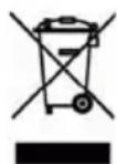
② Hardware overview
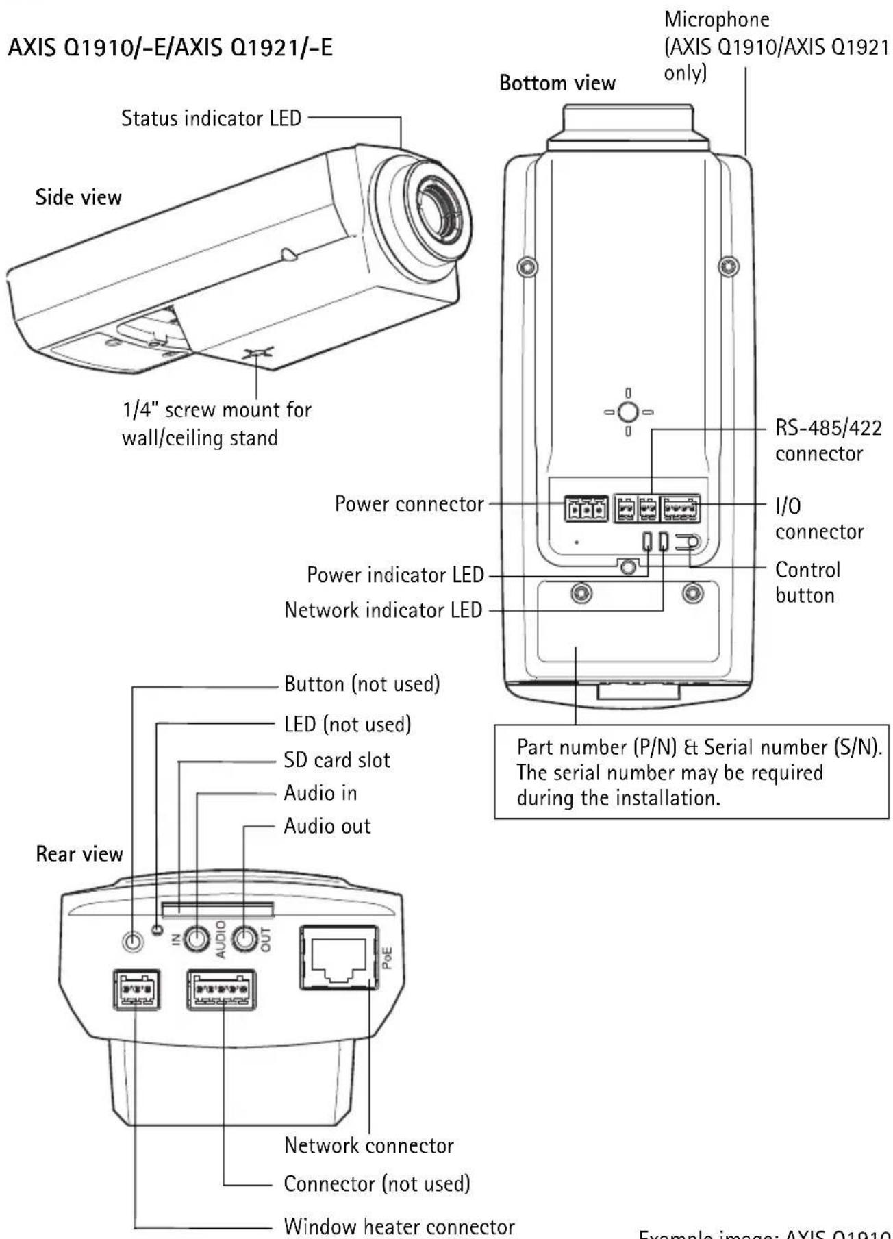
AXIS Q1910-E/AXIS Q1921-E
3 Install the hardware
For outdoor use, please install AXIS Q1910-E/AXIS Q1921-E, or see www.axis.com for more information on outdoor housing and other accessories.
Install AXIS Q1910/AXIS Q1921
The instructions below describe the installation of AXIS Q1910/AXIS Q1921.
- Attach the metal stand to the camera and make sure that the screws and plugs are appropriate for the material (e.g. wood, metal, sheet rock, stone).
- Connect the cables, see Connect the cables, on page 10.
Install AXIS Q1910-E/AXIS Q1921-E
The instructions below describe the installation of AXIS Q1910-E/AXIS Q1921-E.
Prepare the network cable
The provided network cable can be connected in several ways. The first option is to use the cable as is, with the pre-mounted rubber gasket.
The second option is to use the provided plastic M20 cable gland, which must be used to achieve an IP66 rating. Using any other cable gland may cause water to seep in and damage the camera.
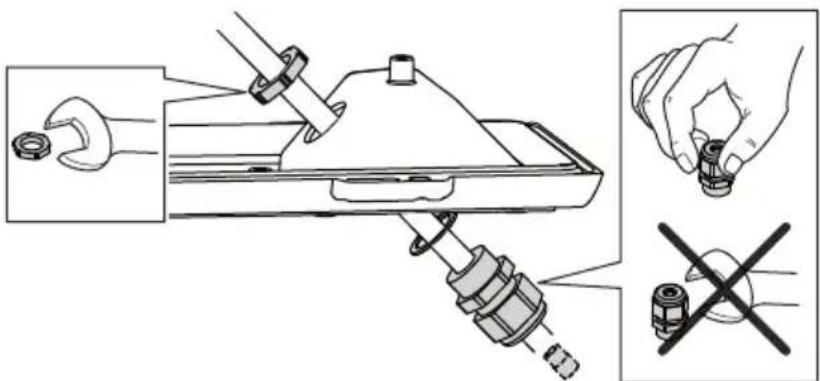
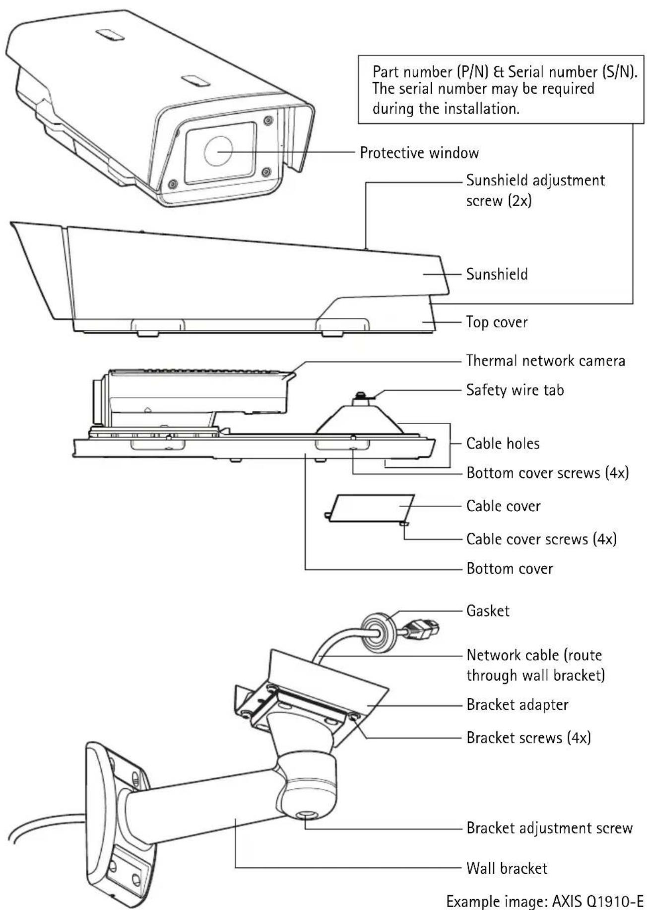
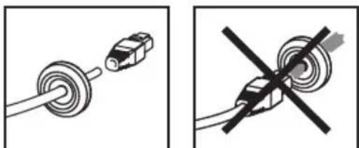
If a cable other than the provided cable is used, you need to prepare a network cable with a gasket. Gently force the cable through the gasket provided and attach a network connector. It may be necessary to pierce a hole in the gasket with the supplied screwdriver.
natural_image
Two diagrams showing a cable being inserted into a connector and a crossed-out resistor symbol (no text or labels)Notes:
- Do not force the network connector into the gasket.
- Do not pierce the gasket with a knife or other sharp object.
Install the wall bracket
- Use the supplied drill template to prepare a wall, ceiling, or pole for installation of the wall bracket.
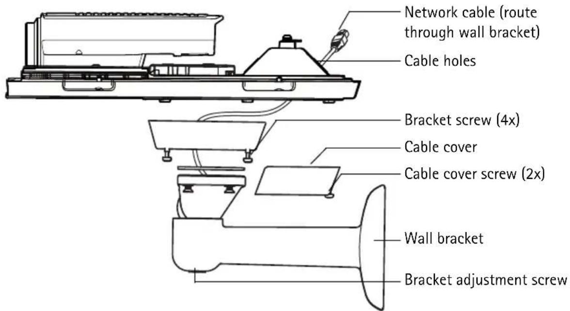
- Route the network cable through the wall bracket, the rubber gasket should be on the bracket adapter end of the wall bracket, see illustration on page 7.
- Install the wall bracket on a wall, ceiling, or pole and make sure that the screws and plugs are appropriate for the material (e.g. wood, metal, sheet rock, stone).
Notes:
- Check that the material is strong enough to support the weight of the camera.
- For more technical specifications, please see the User's Manual, available on the CD included in this package, or from www.axis.com
Install the camera on the bracket
- Install the camera with the bottom cover on the bracket and tighten the bracket screws.
- Remove the gasket from one of the holes in the bottom cover, see illustration on page 7.
- Route the cable through the hole and attach the cable gasket to the hole.
- Connect the cables, see Connect the cables, on page 10.
- Take the top cover and attach the safety wire to the tab on the bottom cover, see illustration on page 7.
- Connect the window heater to the window heater connector on the thermal camera.
- Install the top cover. Make sure to tighten diagonally opposite bottom cover screws a few turns at a time until all are tight. This will help ensure that the bottom cover gasket is compressed evenly. Do not attempt to tighten the screws completely the first time.
- Install the cable cover and tighten the cable cover screws.
-
Loosen the sunshield adjustment screws and adjust the sunshield to the front position.
-
Loosen the bracket adjustment screw to aim the camera to the point of interest. See Access the video stream, on page 15 for information on how to view the video stream.
Connect the cables
- Optionally insert an SD memory card (not included) into the SDHC (Secure Digital High Capacity) card slot. A standard or high capacity SD card is required to store images locally in the camera.
- Optionally connect external input/output devices. See page 18 for information on the terminal connector pins.
- Optionally connect an active speaker and/or external microphone.
- Connect the camera to the network using a shielded network cable.
-
Connect power, using one of the methods listed below:
-
PoE (Power over Ethernet, Class 3). If available, this is automatically detected when the network cable is connected.
-
Connect an external power adapter to the power connector block, see Unit connectors, on page 18 for wiring information.
-
Check that the indicator LEDs indicate the correct conditions. See the table on page 20 for further details.

Assign an IP address
Most networks today have a DHCP server that automatically assigns IP addresses to connected devices. If your network does not have a DHCP server the network camera will use 192.168.0.90 as the default IP address.
If you would like to assign a static IP address, the recommended method in Windows is either AXIS IP Utility or AXIS Camera Management. Depending on the number of cameras you wish to install, use the method that best suits your purpose.
Both of these free applications are available on the Axis Network Video Product CD supplied with this product, or they can be downloaded from www.axis.com/techsup
| Method Recommended for Operating system | |||
 | AXIS IP UtilitySee page 11 | Single cameraSmall installations | Windows |
 | AXIS Camera ManagementSee page 12 | Multiple camerasLarge installationsInstallation on a different subnet | Windows 2000Windows XP ProWindows 2003 ServerWindows VistaWindows 7 |
Notes:
- If assigning the IP address fails, check that there is no firewall blocking the operation.
- For other methods of assigning or discovering the IP address, e.g. in other operating systems, see page 16.
AXIS IP Utility - single camera/small installation
AXIS IP Utility automatically discovers and displays Axis devices on your network. The application can also be used to manually assign a static IP address.
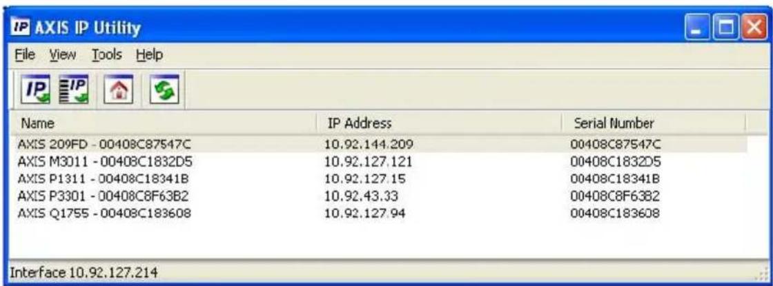
Note that the computer running AXIS IP Utility must be on the same network segment (physical subnet) as the network camera.
Automatic discovery
- Check that the network camera is connected to the network and that power has been applied.
- Start AXIS IP Utility.
- When the camera appears in the window, double-click it to open its home page.
- See page 14 for instructions on how to assign the password.
Assign the IP address manually (optional)
- Acquire an unused IP address on the same network segment as your computer.
- Select the network camera in the list.
- Click the Assign new IP address to the selected device button IP and enter the IP address.
- Click Assign and follow the on-screen instructions. Note that the camera must be restarted within 2 minutes for the new IP address to be set.
- Click Home Page to access the camera's web pages.
- See page 14 for instructions on how to set the password.
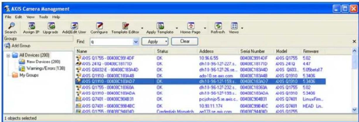
AXIS Camera Management - multiple cameras/large installations
AXIS Camera Management can automatically discover multiple Axis devices, show connection status, manage firmware upgrades and set IP addresses.
Automatic discovery
- Check that the camera is connected to the network and that power has been applied.
- Start AXIS Camera Management. When the network camera appears in the window, right-click the link and select Live View Home Page.
- See page 14 for instructions on how to set the password.
Assign an IP address in a single device
- Select the network camera in AXIS Camera Management and click the Assign IP button.
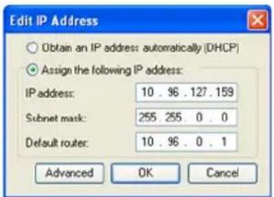
- Select Assign the following IP address and enter the IP address, subnet mask and default router the device will use.
- Click OK.
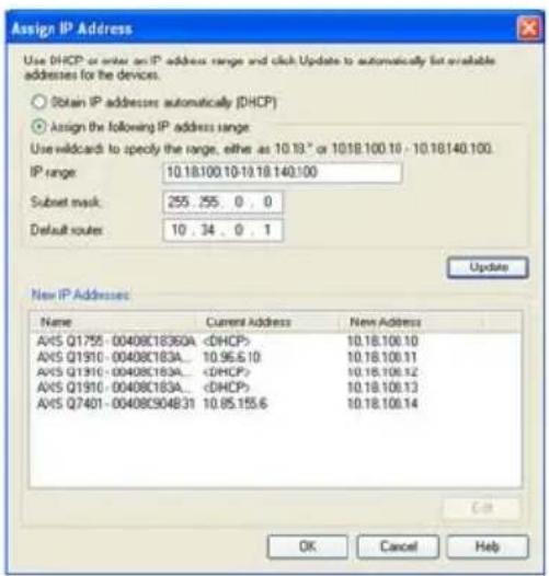
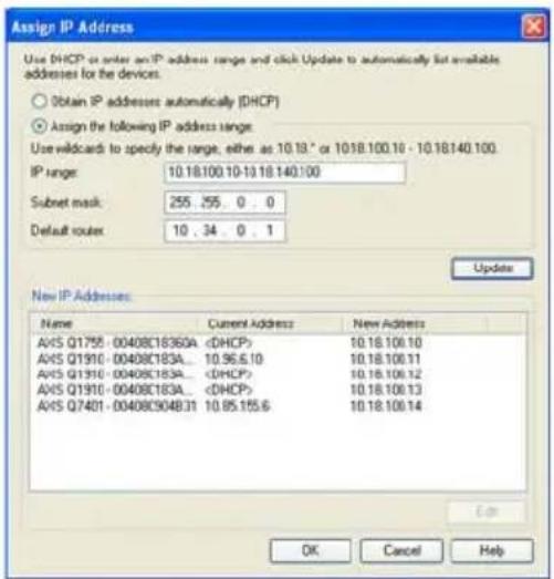
Assign IP addresses in multiple devices
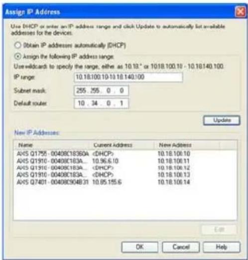
AXIS Camera Management speeds up the process of assigning IP addresses to multiple devices, by suggesting IP addresses from a specified range.
- Select the devices you wish to configure (different models can be selected) and click the Assign IP button.
- Select Assign the following IP address range and enter the range of IP addresses, the subnet mask and default router the devices will use.
- Click Update. Suggested IP addresses are listed under New IP Addresses and can be edited by selecting a device and clicking Edit.
- Click OK.

Set the password
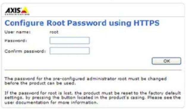
To gain access to the product, the password for the default administrator user root must be set. This is done in the 'Configure Root Password' dialog, which is displayed when the network camera is accessed for the first time.
To prevent network eavesdropping when setting the root password, this can be done via an encrypted HTTPS connection, which requires an HTTPS certificate.
Note: HTTPS (Hypertext Transfer Protocol over SSL) is a protocol used to encrypt the traffic between web browsers and servers. The HTTPS certificate controls the encrypted exchange of information.
To set the password via a standard HTTP connection, enter it directly in the first dialog shown below.
To set the password via an encrypted HTTPS connection, follow these steps:
- Click the Create self-signed certificate button.
- Provide the requested information and click OK. The certificate is created and the password can now be set securely. All traffic to and from the network camera is encrypted from this point on.
- Enter a password and then re-enter it to confirm the spelling. Click OK. The password has now been configured.
![To create an HTTPS connection, start by clicking this button. Create Certificate Secure configuration of the root password via HTTPS requires a self-signed certificate. Create self-signed certificate... Configure Root Password User name: root Password: Confirm password: Create Self-Signed Certificate Common name: 10.96.127.232 Validity: 365 days [1..9999] *The name of the entity to be certified, i.e. the IP address or host name of this product. OK Cancel Once the certificate is created, this page will close and you will be able to configure the root password via HTTPS. The password for the pre-configured administrator root must be changed before the product can be used. If the password for root is lost, the product must be reset to the factory default settings, by pressing the button located in the product's casing. Please see the user documentation for more information. Configure Root Password using User name: root Password: Confirm password:](/content/2026/06/1255384/images/3da07a47e841b5f6b6332971f9cc408e59f0804196b7cc45d1f33f579752fce2.jpg)
To configure the password directly via an unencrypted connection, enter the password here.
- To log in, enter the user name "root" in the dialog as requested.
Note: The default administrator user name root cannot be deleted.
- Enter the password as set above, and click OK.
Note: If the password is lost, the camera must be reset to the factory default settings. See page 21.
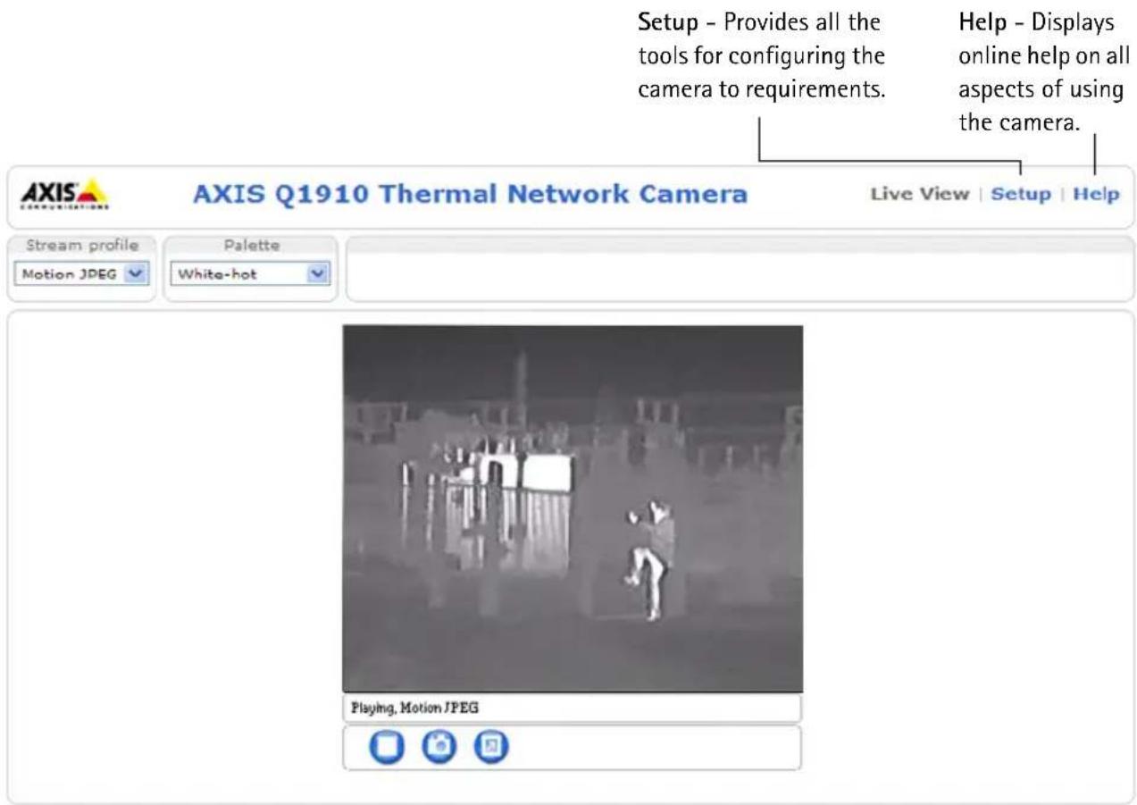
Access the video stream
The Live View page of the network camera is displayed, with links to the Setup tools, which allow you to customize the camera.
If required, click Yes to install AMC (AXIS Media Control), which allows viewing of the video stream in Internet Explorer. You will need administrator rights on the computer to do this.
If required, click the link to install missing decoders.
Note: To install AMC in Windows Vista and Windows 7, you must run Internet Explorer as an administrator. Right-click the Internet Explorer icon and select Run as administrator.
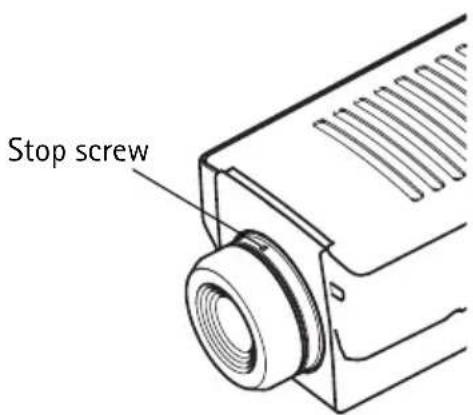
Focus adjustment - AXIS Q1921/-E
If required, follow these instructions to focus AXIS Q1921/-E:
- Unscrew the stop screw on the lens, using a slotted screwdriver 1.8 mm.
- Adjust lens to focus as required.
- Tighten the stop screw.
Note:
AXIS Q1910/-E has a fixed-focus lens set to infinity and cannot be adjusted.
Other methods of setting the IP address
The table below shows the other methods available for setting or discovering the IP address. All methods are enabled by default, and all can be disabled.
| Use in operating system | Notes | |
| UPnPTM | Windows When enabled on your computer, the camera is automatically detected and added to “My Network Places.” | |
| Bonjour | MAC OSX (10.4 or later) | Applicable to browsers with support for Bonjour. Navigate to the Bonjour bookmark in your browser (e.g. Safari) and click on the link to access the camera’s web pages. |
| AXIS Dynamic DNS Service | All A free service from Axis that allows you to quickly and simply install your camera. Requires an Internet connection with no HTTP proxy. See www.axiscam.net for more information. | |
| ARP/Ping | All See below. The command must be issued within 2 minutes of connecting power to the camera. | |
| DHCP server | All To view the admin pages for the network DHCP server, see the server's own documentation. | |
AXIS Video Hosting System (AVHS)
The camera can also be connected to an AVHS service for hosted video. If you have subscribed to an AVHS service, follow the instructions in the Service Provider's Installation Guide. For more information and help to find a local AVHS Service Provider, go to www.axis.com/hosting
A Camera owner authentication key is supplied with this product. The key is associated with the camera's unique serial number (S/N) as shown on the top of the label.
Note:
Save the key for future reference.
Set the IP address with ARP/Ping
- Acquire an IP address on the same network segment your computer is connected to.
- Locate the serial number (S/N) on the product label on the camera.
- Open a command prompt on your computer and enter the following commands:
| Windows syntax: Windows example: | |
| arp -s <IP Address> <Serial Number> ping -l 408 -t <IP Address> | arp -s 192.168.0.125 00-40-8c-18-10-00 ping -l 408 -t 192.168.0.125 |
| UNIX/Linux/Mac syntax: UNIX/Linux/Mac example: | |
| arp -s <IP Address> <Serial Number> temp ping -s 408 <IP Address> | arp -s 192.168.0.125 00:40:8c:18:10:00 temp ping -s 408 192.168.0.125 |
- Check that the network cable is connected to the camera and then start/restart the camera, by disconnecting and reconnecting power.
- Close the command prompt when you see 'Reply from 192.168.0.125: ...' or similar.
- In your browser, type in http://
in the Location/Address field and press Enter on your keyboard.
Notes:
- To open a command prompt in Windows: from the Start menu, select Run... and type cmd. Click OK.
- To use the ARP command in WWindows Vista, right-click the command prompt icon and select Run as administrator.
- To use the ARP command on a Mac OS X, use the Terminal utility in Application > Utilities.
Unit connectors
Network – RJ-45 Ethernet connector. Supports PoE (Power over Ethernet, class 3). Using shielded cables is recommended.
Audio in - 3.5 mm input for a mono microphone, or a line-in mono signal (left channel is used from a stereo signal). An external microphone must be used to for audio detection.
Audio out - 3.5 mm output for audio (line level), can be connected to a public address (PA) system or an active speaker with a built-in amplifier. A pair of headphones can also be connected. A stereo connector must be used for audio out.
RS-485/422 - two 2-pin terminal blocks for RS-485/422 serial interface used to control auxiliary equipment, e.g. PTZ devices.
The RS-485/422 serial port can be configured in the following port modes:
- Bidirectional RS-485 half-duplex port for data transmission using two wires, one combined RX/TX pair.
- Bidirectional RS-485 full-duplex port for data transmission using four wires, one RX pair and one TX pair.
- Unidirectional RS-422 port for transmitting or receiving data using two wires, RX- or TX pair.
- Bidirectional RS-422 full-duplex port for data transmission (point-to-point) using four wires, one RX pair and one TX pair.
RS-485/422
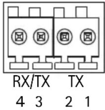
| Function Pin Notes | ||
| RS 485/422TX(A) 1 TX pair for RS-422 and RS 485/422TX(B) 2 | 2 and | |
| 4-wire RS-485 | ||
| RS-485A alt RS-485/422RX(A) 3 RX | pair for all modes (combined RX/TX for 2-wire RS-485) | |
| RS-485B alt RS-485/422RX(B) 4 | ||
SDHC memory card slot - High capacity SD memory card used for local recording and removable storage.
Power - 3-pin terminal block 8-20 V DC or 20-24 V AC.
| Model DC power input | AC power input | |
| AXIS Q1910 8-20 V DC | max 8.2 W 20-24 V AC, max 12.7 VA | |
| AXIS Q1910-E 8-20 V | DC, max 11.2 W 20-24 V AC, max 17.4 VA | |
| AXIS Q1921 8-20 V DC | max 6 W 20-24 V AC, max 10 VA | |
| AXIS Q1921-E 8-20 V | DC, max 10 W 20-24 V AC, max 16 VA | |
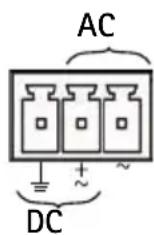
! CAUTION! - Incorrect connection of the wires could cause damage to the camera.
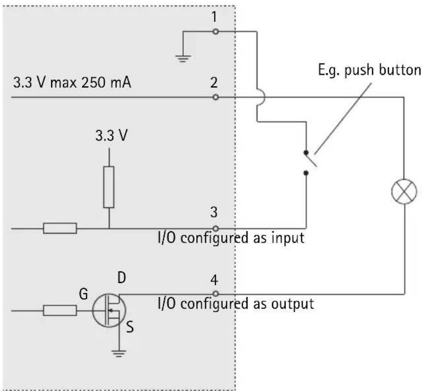
I/O terminal connector – Used in applications for e.g. motion detection, event triggering, time lapse recording and alarm notifications. In addition to an auxiliary power and a GND pin, the network camera has 2 pins that can be configured as either input or output. These pins provide the interface to:
I/O
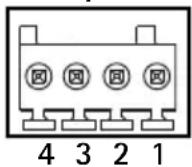
- Transistor output – For connecting external devices such as relays and LEDs. Connected devices can be activated by AXIS VAPIX API, output
buttons on the Live View page or by an Event Type. The output will show as active (shown under Events > Port Status) if the alarm device is activated.
- Digital input – An alarm input for connecting devices that can toggle between an open and closed circuit, for example: PIRs, door/window contacts, glass break detectors, etc. When a signal is received the state changes and the input becomes active (shown under Events > Port Status.)
| Function | Pin number | Notes Specifications | |
| GND 1 Ground | |||
| 3.3 V DC Power | 2 Can be used | to power auxiliary equipment.Note:This pin can only be used as power out. | Max load = 250 mA |
| Configurable (Input or Output) | 3 - 4 Digital input | - Connect to GND to activate, or leave floating (or unconnected) to deactivate. | Min input = - 40 V DCMax input = + 40 V DCCrecommended range:0 V D C to + 20 V D C |
| Digital output - Uses an open-drain NFET transistor with the source connected to GND.If used with an external relay, a diode must be connected in parallel with the load, for protection against voltage transients. | Max load = 100 mAMax voltage = + 40 V DCCrecommended voltage:Up to +20 V DC | ||
Connection diagram
LED indicators
| LED Color Indication | ||
| Network | Green | Steady for connection to a 100 Mbit/s network. Flashes for network activity. |
| Amber | Steady for connection to 10 Mbit/s network. Flashes for network activity. | |
| Unlit No network connection. | ||
| Status Green Steady green for normal operation.Note: The Status LED can be configured to be unlit during normal operation, or to flash only when the camera is accessed. To configure, go to Setup > System Options > LED. See the online help files for more information. | ||
Resetting to the Factory Default Settings
This will reset all parameters, including the IP address, to the Factory Default settings:
- Disconnect power from the camera.
- Press and hold the control button and reconnect power.
- Keep the control button pressed until the status indicator displays amber (this may take up to 15 seconds).
- Release the control button. When the status indicator displays green (which can take up to 1 minute) the process is complete and the camera has been reset.
- Re-assign the IP address, using one of the methods described in this document.
It is also possible to reset parameters to the original factory default settings via the web interface. For more information, please see the online help or the user's manual.
Accessing the camera from the Internet
Once installed, your network camera is accessible on your local network (LAN). To access the camera from the Internet, network routers must be configured to allow incoming traffic, which is usually done on a specific port.
- HTTP port (default port 80) for viewing and configuration
- RTSP port (default port 554) for viewing H.264 video streams
Please refer to the documentation for your router for further instructions. For more information on this and other topics, visit the Axis Support Web at www.axis.com/techsup
Further information
The user's manual is available from the Axis Web site at www.axis.com or from the Axis Network Video Product CD supplied with this product.
Tip!
Visit www.axis.com/techsup to check if there is updated firmware available for your network camera. To see the currently installed firmware version, see Setup > About.
Mesures de sécurité
natural_image
Two diagrams showing a cable being inserted into a connector and then crossed out with a diagonal line (no text or symbols)Remarques :
Installation du support mural
![Create Certificate Secure configuration of the root password via HTTPS requires a self-signed certificate. Create self-signed certificate... Configure Root Password User name: root Password: Confirm password: The password for the pre-configured administrator root must be changed before the product can be used. If the password for root is lost, the product must be reset to the factory default settings, by pressing the button located in the product's casing. Please see the user documentation for more information. Pour créer une connexion H cliquez sur ce bouton. Create Self-Signed Certificate Common name: 10.96.127.232 Validity: 365 days [1..9999] *The name of the entity to be certified, i.e. the IP address or host name of this product. OK Cancel Once the certificate is created, this page will close and you will be able to configure the root password via HTTPS. AXIS® Configure Root Password u User name: root Password: Confirm password:](/content/2026/06/1255384/images/dfc4963320aede3b88f04b4be43d1066410a91814b4375f17dba85eff9638e69.jpg)
natural_image
Two diagrams showing a cable being inserted into a connector and then crossed out by a diagonal line (no text or symbols present)Hinweise:
Zugriff auf den Videostrom
Die Seite „Live View“ (Live-Ansicht) der Netzwerk-Kamera wird geöffnet. Sie enthält Links zu Setup-Tools, mit denen Sie die Kamera Ihren Anforderungen entsprechend anpassen können. Klicken Sie bei Bedarf auf Yes (Ja), um AMC (AXIS Media Control) zu installieren. Nach Abschluss der Installation können Sie Videoströme in Internet Explorer anzeigen. Hierzu müssen Sie über Administratorrechte für den Computer verfügen. Falls nötig, klicken Sie auf den Link, um fehlende Decoder zu installieren. Hinweis: Für die Installation von AMC unter Windows Vista und Windows 7 müssen Sie Internet Explorer als Administrator ausführen. Klicken Sie mit der rechten Maustaste auf das Internet Explorer-Symbol und wählen Sie „Als Administrator ausführen“. Fokussierung – AXIS Q1921/-E
Führen Sie, falls nötig, die folgenden Schritte aus, um die Fokussierung der AXIS Q1921/-E durchzuführen: 1. Lösen Sie die Arretierschraube am Objektiv mit einem 1,8-mm-Schlitzschraubenzieher. 2. Stellen Sie die erforderliche Bildschärfe ein. 3. Ziehen Sie die Arretierschraube fest. Hinweis: Das Kameramodell AXIS Q1910/-E verfügt über ein Objektiv mit festem Fokus. Der Fokus ist werkseitig auf unendlich eingestellt und kann nicht geändert werden. Andere Methoden zum Festlegen der IP-Adresse
Diese Tabelle bietet einen Überblick über weitere Methoden, die IP-Adresse festzulegen bzw. zu ermitteln. Alle Methoden sind standardmäßig aktiviert und können deaktiviert werden.| Verwendung im Betriebssystem | Hinweise | |
| UPnP ^TM | Windows Wenn die | Funktion auf dem Computer aktiviert ist, wird die Kamera automatisch erkannt und zu „Netzwerkumgebung“ hinzugefügt. |
| Bonjour | MAC OSX(10.4 oder höher) | Kann nur bei Browsern verwendet werden, die Bonjour unterstützen. Navigieren Sie zum Bonjour-Lesezeichen Ihres Browsers (z. B. Safari) und klicken Sie auf den Link, um auf die Webseiten der Kamera zu gelangen. |
| AXIS Dynamic DNS Service | Alle Ein kostenloser | Service von Axis, mit dem Sie Ihre Kamera schnell und einfach installieren können. Eine Internetverbindung ohne HTTP-Proxyserver ist Voraussetzung. Weitere Informationen hierzu finden Sie auf „www.axiscam.net“. |
| ARP/Ping | Alle Siehe unten. | Der Befehl muss innerhalb von 2 Minuten erfolgen, nachdem die Kamera an das -Stromnetz angeschlossen wurde. |
| DHCP-Server | Alle Hinweise zum | Anzeigen der Administrationsseiten des DHCP-Servers im Netzwerk finden Sie in der Serverdokumentation. |
AXIS Video Hosting System (AVHS)
Die Kamera kann auch an einen AVHS-Service für gehostetes Video angeschlossen werden. Wenn Sie einen AVHS-Service abonniert haben, befolgen Sie die Anweisungen im Installationshandbuch des Dienstanbieters. Weitere Informationen zu lokalen AVHS-Dienstanbietern finden Sie unter „www.axis.com/hosting“. Im Lieferumfang dieses Produkts ist ein Authentifizierungsschlüssel für den Kameraeigentümer enthalten. Der Schlüssel ist der eindeutigen Seriennummer (S/N) der Kamera zugeordnet, die sich oben auf dem Etikett befindet.Hinweis:
Bewahren Sie den Schlüssel auf, um ihn später verfügbar zu haben.Zuweisen der IP-Adresse per ARP/Ping
1. Wählen Sie eine IP-Adresse aus dem Netzwerksegment, in dem sich auch Ihr Computer befindet. 2. Suchen Sie die Seriennummer (S/N) auf dem Produktaufkleber an der Kamera. 3. Öffnen Sie auf Ihrem Computer die Eingabeaufforderung und geben Sie die folgenden Befehle ein:| Windows-Syntax: Beispiel für Windows: | |
| arp -s <IP-Adresse> <Seriennummer> ping -l 408 -t <IP-Adresse> | arp -s 192.168.0.125 00-40-8c-18-10-00 ping -l 408 -t 192.168.0.125 |
| Syntax unter UNIX/Linux/Mac: | Beispiel für UNIX/Linux/Mac: |
| arp -s <IP-Adresse> <Seriennummer> temp ping -s 408 <IP-Adresse> | arp -s 192.168.0.125 00:40:8c:18:10:00 temp ping -s 408 192.168.0.125 |
Hinweise:
- So öffnen Sie die Eingabeaufforderung unter Windows: Wählen Sie im Startmenü die Option „Ausführen..." aus und geben Sie „cmd“ ein. Klicken Sie auf OK. - Klicken Sie zum Eingeben des Befehls „ARP“ unter Windows Vista mit der rechten Maustaste auf das Befehlszeilensymbol und wählen Sie Als Administrator ausführen. - Verwenden Sie zum Eingeben des Befehls „ARP“ unter Mac OS X das Dienstprogramm „Terminal“, das Sie unter „Anwendung > Dienstprogramme“ finden.Geräteanschlüsse
Netzwerk – RJ-45-Ethernetanschluss. Unterstützt PoE (Power over Ethernet, Klasse 3). Die Verwendung von abgeschirmten Kabeln wird empfohlen. Audio-Eingang - 3.5-mm-Anschluss für ein Monomikrofon oder ein Monosignal (linker Kanal wird von einem Stereosignal benutzt). Für die Audioerkennung muss ein externes Mikrofon verwendet werden. Audio-Ausgang - 3.5-mm-Audio-Ausgang (Leistungsstufe) zum Anschließen einer Rundrufanlage (PA) oder eines Aktivlautsprechers mit integriertem Verstärker. Auch ein Kopfhörer kann angeschlossen werden. Ein Stereostecker muss für die Audioausgabe verwendet werden. RS-485/422-- Zwei 2-polige Anschlussblöcke für serielle Schnittstellen vom Typ RS-485/422 zur Steuerung von Zusatzgeräten, wie z. B. PTZ-Geräten. Der serielle RS-485/422-Anschluss kann in den folgenden Anschlussmodi konfiguriert werden: - Bidirektionaler RS-485-Halbduplex-Anschluss für die Datenübertragung über zwei Draht, ein kombiniertes RX/TX-Paar. - Bidirektionaler RS-485-Vollduplex-Anschluss für die Datenübertragung über vier Draht, ein RX-Paar und ein TX-Paar. - Unidirektionaler RS-422-Anschluss für die Datenübertragung bzw. den Datenempfang über zwei Draht, RX- oder TX-Paar. - Bidirektionaler RS-422-Vollduplex-Anschluss für die Datenübertragung (Punkt-zu-Punkt) über vier Draht, ein RX-Paar und ein TX-Paar.| Funktion Pol Hinweise | ||
| RS 485/422TX(A) 1 TX-Paar für RS-42 und RS-485 mit 4 Drähten | ||
| RS 485/422TX(B) 2 | ||
| RS-485A alt RS-485/422RX(A) | 3 | RX-Paar für alle Modi (kombinierter RX/TX für RS-485 mit 2 Drähten) |
| RS-485B alt RS-485/422RX(B) 4 | ||
| Modell Gleichstromeingang Wechselstromeingang | |
| AXIS Q1910 8 bis 20 V Gleichstrom, max. 8,2 W 20 bis 24 V Wechselstrom, max. 12,7 VA | |
| AXIS Q1910-E 8 bis 20 V Gleichstrom, max. 11,2 W 20 bis 24 V Wechselstrom, max. 17,4 VA | |
| AXIS Q1921 8 bis 20 V Gleichstrom, max. 6 W 20 bis 24 V Wechselstrom, max. 10 VA | |
| AXIS Q1921-E 8 bis 20 V Gleichstrom, max. 10 W | 20 bis 24 V Wechselstrom, max. 16 VA |
| Funktion | Anschluss-nummer | Hinweise Spezifikationen | |
| Masse (GND) 1 | Masse | ||
| 3.3 V Gleichstrom | 2 Kann für die Stromversorgung von Zusatzgeräten verwendet werden. Hinweis: Dieser Kontakt kann nur für den Stromausgang verwendet werden. | Max. Stromstärke = 250 mA | |
| Konfigurierbar (Ein- oder Ausgang) | 3 - 4 Digitaleingang: Zum Aktivieren mit dem Massekontakt verbinden; zum Deaktivieren nicht anschließen. | Min. Eingang = - 40 V Gleichstrom Max Eingang = + 40 V Gleichstrom Empfohlener Bereich: 0 V Gleichstrom bis +20 V Gleichstrom | |
| Digitalausgang: Verwendet einen Open-Drain-NFET-Transistor, wobei die Quelle mit der Masse verbunden ist. Zum Schutz vor Spannungsspitzen muss bei der Kombination mit einem externen Relais eine Diode parallel zur Last geschaltet werden. | |||
| Max. Stromstärke = 100 mA Max. Spannung = + 40 V Gleichstrom Empfohlene Spannung: Bis zu +20 V Gleichstrom | |||
Anschlussschaltbild
LED-Anzeigen
| LED Farbe | Bedeutung | |
| Netzwerk | Grün | Leuchtet dauerhaft bei Verbindung mit einem 100-MBit/s-Netzwerk. Blinkt bei Netzwerkaktivität. |
| Gelb Leuchtet | dauerhaft bei Verbindung mit einem 10-MBit/s-Netzwerk. Blinkt bei Netzwerkaktivität. | |
| Leuchtet nicht | Keine Netzwerkverbindung vorhanden. | |
| Status Grün | Leuchtet bei | Normalbetrieb konstant grün.Hinweis: Die Status-LED kann so konfiguriert werden, dass sie bei normalem Betrieb nicht leuchtet oder nur dann blinkt, wenn auf die Kamera zugegriffen wird. Diese Konfiguration können Sie unter Setup > System Options > LED (Setup > Systemoptionen > LED) vornehmen. Weitere Informationen hierzu finden Sie in der Online-Hilfe. |
| Gelb Leuchtet | konstant beim Einschalten und beim Wiederherstellen der Werkseinstellungen bzw. von vorherigen Einstellungen. | |
| Rot Blinkt langsam bei Aktualisierungsfehler. | ||
| Betriebs-anzeige | Grün Normaler Betrieb. | |
| Gelb Blinkt grün/gelb während Firmware-Aktualisierung. | ||
Wiederherstellen der werkseitigen Standardeinstellungen
Gehen Sie wie folgt vor, um sämtliche Parameter einschließlich der IP-Adresse auf die werkseitigen Standardeinstellungen zurückzusetzen: 1. Trennen Sie die Kamera von der Stromversorgung. 2. Halten Sie die Steuertaste gedrückt und schließen Sie den Netzstecker wieder an. 3. Halten Sie die Steuertaste so lange gedrückt, bis die Statusanzeige gelb aufleuchtet (dies kann bis zu 15 Sekunden dauern). 4. Lassen Sie die Steuertaste los. Sobald die Statusanzeige grün leuchtet (dies kann bis zu einer Minute dauern), ist die Kamera auf die werkseitigen Standardeinstellungen zurückgesetzt. 5. Legen Sie die IP-Adresse erneut fest. Wenden Sie dabei eines der in diesem Handbuch beschriebenen Verfahren an. Die Parameter können auch über die Weboberfläche auf die werkseitigen Einstellungen zurückgesetzt werden. Weitere Informationen dazu finden Sie in der Online-Hilfe und im Benutzerhandbuch.Zugriff auf die Kamera über das Internet
Sobald die Netzwerk-Kamera installiert ist, können Sie in Ihrem lokalen Netzwerk (LAN) darauf zugreifen. Um auch über das Internet auf die Kamera zugreifen zu können, müssen Sie die Netzwerk-Router so konfigurieren, dass diese den entsprechenden eingehenden Datenverkehr zulassen, was üblicherweise durch Zuweisung eines bestimmten Ports geschieht. - HTTP-Port (standardmäßig Port 80) für die Anzeige und Konfiguration - RTSP-Port (standardmäßig Port 554) für die Anzeige von H.264-Videoströmen Ausführliche Informationen dazu finden Sie in der Dokumentation des Routers. Weitere Informationen zu diesem und zu anderen Themen erhalten Sie auf der Axis Support-Website unter „www.axis.com/techsup“.Weitere Informationen
Das Benutzerhandbuch ist auf der Axis Website unter „http://www.axis.com“ erhältlich und befindet sich auch auf der mitgelieferten CD für Axis-Netzwerkvideoprodukte. Tipp! Unter „www.axis.com/techsup“ finden Sie Firmware-Aktualisierungen für Ihre Netzwerk-Kamera. Informationen zur aktuellen Firmware-Version finden Sie unter „Setup > Info“.Precauzioni
Leggere per intero e con attenzione questa Guida all'installazione prima di installare il prodotto. Conservare la Guida all'installazione per ulteriori riferimenti.ATTENZIONE!
- Quando si trasporta un prodotto Axis, utilizzare l'imballo originale o un imballo equivalente per evitare danni al prodotto. - Conservare il prodotto Axis in un ambiente asciutto e ventilato. Mantenere la temperatura di stoccaggioe di funzionamento all'interno dei limiti stabiliti nella Guida per l'utente disponibile sul CD incluso nella confezione oppure al sito web www.axis.com). - Evitare di esporre il prodotto Axis a vibrazioni, urti o pressioni eccessive e non installare la telecamera su staffe instabili, superfici o pareti instabili o vibranti, poiché in tal modo si potrebbe danneggiare il prodotto. - Per l'installazione del prodotto Axis, utilizzare solo attrezzi manuali, l'utilizzo di utensili elettrici o l'applicazione di una forza eccessiva potrebbero danneggiare il prodotto. - Non rivolgere l'obiettivo della telecamera verso il sole o altre sorgenti di radiazioni molto intense poiché si potrebbe danneggiare il sensore. - Non utilizzare sostanze chimiche, agenti caustici o detergenti aerosol. Utilizzare un panno umido per la pulizia. - Utilizzare solo accessori e parti di ricambio forniti o consigliati da Axis. - Non tentare di riparare da soli il prodotto, ma contattare Axis o il rivenditore Axis per qualsiasi argomento relativo all'assistenza tecnica.IMPORTANTE!
- Questo prodotto Axis deve essere utilizzato in conformità alle leggi e alle regolamentazioni locali. - Per utilizzare la videocamera AXIS Q1910/AXIS Q1921 all'esterno, è necessario installarla in un alloggiamento per esterni approvato. Installare la telecamera AXIS Q1910-E/AXIS Q1921-E per uso in ambienti esterni o visitare il sito www.axis.com per ulteriori informazioni sugli alloggiamenti per esterni e altri accessori. - Non installare la telecamera vicino a sorgenti di calore poiché le oscillazioni di temperatura potrebbero influire sulla qualità dell'immagine. - La telecamera deve essere installata da un professionista preparato. Per l'installazione, rispettare i regolamenti nazionali e locali in vigore.Sostituzione della batteria
Questo prodotto Axis utilizza una batteria al litio CR2032 da 3,0V come sorgente di alimentazione per l'orologio in tempo reale (RTC) interno. In condizioni normali, la batteria dura almeno 5 anni. Una scarsa potenza della batteria influisce sul funzionamento dell'RTC, causandone la reimpostazione a ogni accensione. Quando la batteria necessita di sostituzione, appare un messaggio di log. La batteria non deve essere sostituita se non è necessario! Se è necessario sostituire la batteria, visitare la pagina web www.axis.com/techsup per assistenza. - La sostituzione non corretta della batteria comporta il pericolo di esplosioni. - Sostituire solo con una batteria uguale o equivalente, come consigliato dal produttore. - Smaltire le batterie usate secondo le istruzioni del produttore.AXIS Q1910/-E & AXIS Q1921/-E Guida all'installazione
Questo documento fornisce le istruzioni necessarie per installare una telecamera termica di rete AXIS Q1910/-E/AXIS Q1921/-E nella rete in uso. Per ulteriori informazioni sull'utilizzo del prodotto, consultare la Guida per l'utente disponibile sul CD incluso nella confezione oppure visitare il sito web all'indirizzo www.axis.comProcedura di installazione
1. Controllare il contenuto della confezione con l'elenco che segue. 2. Panoramica dell'hardware. Vedere pagina 60. 3. Installazione dell'hardware. • Installazione della telecamera AXIS Q1910/AXIS Q1921. Vedere pagina 62. • Installazione della telecamera AXIS Q1910-E/AXIS Q1921-E. Vedere pagina 62. • Collegamento dei cavi. Vedere pagina 64. 4. Assegnazione di un indirizzo IP. Vedere pagina 65. 5. Impostare la password. Vedere a pagina 68. Importante! Questo prodotto deve essere usato in conformità alle leggi e ai regolamenti locali.1 Contenuto della confezione
| Elemento Modelli/varianti/note | |
| Telecamera di rete AXIS | S Q1910/-E (8.3 fps)AXIS Q1921/-E (8.3/30 fps)Nota: I modello con velocità di trasmissione superiori a 9 fps possono essere soggetti a norme di controllo dell'esportazione |
| Connettore della morsettiera | connettore a 4 pin per la connessione di dispositivi esterni alla morsettiera di I/O; connettore a 3 pin per la connessione all'alimentazione; connettore a 2 pin per la connessione RS-485/422 |
| Base per telecamera (AXIS Q1910/AXIS Q1921) Base in metallo con viti di montaggio | |
| Staffa per il montaggio a parete | (AXIS Q1910-E/AXIS Q1921-E) Staffa per il montaggio a muro con canalina interna per cavi |
| Strumenti (AXIS Q1910-E/AXIS Q1921-E) Cacciavite Torx T20; Chiave Allen | |
| Cavo di rete | (AXIS Q1910-E/AXIS Q1921-E) Cavo di rete per esterni 5 m (16 ft.) con guarnizione; Pressacavi M20 (per IP66) |
| CD | CD del prodotto, che comprende le utility di installazione e altro software nonché la documentazione del prodotto. |
| Materiali stampati | Guida all'installazione della AXIS Q1910/-E/AXIS Q1921/-E (questo documento); Documento di garanzia Axis; Etichetta aggiuntiva con numero di serie (2x); Chiave di autenticazione AVHS |
Panoramica dell'hardware
 AXIS Q1910-E/AXIS Q1921-E  Installazione dell'hardware
Per l'uso esterno, installare la telecamera AXIS Q1910-E/AXIS Q1921-E o visitare il sito www.axis.com per ulteriori informazioni sugli alloggiamenti per esterni e altri accessori,Installazione della telecamera AXIS Q1910/AXIS Q1921
Le istruzioni che seguono descrivono l'installazione della telecamera AXIS Q1910/AXIS Q1921. 1. Applicare la base in metallo alla telecamera e assicurarsi che le viti siano adatte al materiale (ed. legno, metallo, cartongesso, pietra). 2. Collegamento dei cavi. Vedere a Collegamento dei cavi, a pagina 64.Installazione della telecamera AXIS Q1910-E/AXIS Q1921-E
Le istruzioni che seguono descrivono l'installazione della telecamera AXIS Q1910-E/AXIS Q1921-E.Preparazione del cavo di rete
Il cavo di rete fornito può essere connesso in svariati modi. La prima opzione consiste nel montare il cavo così com'è, con la guarnizione in gomma preinstallata. La seconda opzione consiste nell'usare il pressacavo in plastica M20 fornito, che deve essere utilizzato per ottenere una protezione di classe IP66. L'utilizzo di qualsiasi altro pressacavo può causare infiltrazioni d'acqua che possono danneggiare la telecamera.  Se si utilizza un cavo diverso da quello fornito, sul cavo di rete è necessario montare una guarnizione. Spingere delicatamente il cavo nella guarnizione fornita e fissarlo al connettore di rete. Può talvolta essere necessario forare la guarnizione con il cacciavite fornito. natural_image
Two diagrams showing a cable being inserted into a ring and then being crossed out by a black diagonal line (no text or symbols present)Note:
- Non spingere a forza il connettore di rete nella guarnizione. - Non forare la guarnizione con un coltello o un altro oggetto appuntito.Installare la staffa di montaggio a parete
1. Utilizzare la maschera di foratura fornita per preparare una parete, un soffitto o un'asta per l'installazione della staffa a parete. 2. Inserire il cavo di rete attraverso la staffa a parete, la guarnizione di gomma dovrebbe essere sull'estremità dell'adattatore della staffa a parete, vedere l'illustrazione a pagina 61. 3. Installare la staffa a parete su una parete, un soffitto o un'asta e assicurarsi che le viti e i connettori siano appropriati per il materiale (ad esempio legno, metallo, cartongesso, pietra).Note:
- Controllare che il materiale sia sufficientemente robusto per sostenere il peso della telecamera. - Per ulteriori specifiche tecniche, consultare la Guida per l'utente disponibile sul CD incluso nella confezione oppure visitare il sito web all'indirizzo www.axis.comInstallare la telecamera sulla staffa
1. Installare la telecamera con la copertura inferiore sulla staffa, quindi serrare le viti della staffa. 2. Rimuovere la guarnizione da uno dei fori della copertura inferiore, vedere illustrazione a pagina 61. 3. Far passare il cavo attraverso il foro e applicare la guarnizione del cavo al foro.  4. Collegamento dei cavi. Vedere a Collegamento dei cavi, a pagina 64. 5. Prendere la copertura superiore e fissare il cavo di sicurezza alla linguetta sulla copertura inferiore, vedere l'illustrazione a pagina 61. 6. Collegare il riscaldatore della finestra all'apposito connettore sulla telecamera termica. 7. Montare la copertura superiore. Assicurarsi di serrare le viti del coperchio pochi giri per volta a coppie diagonalmente opposte, fino a che non sono tutte serrate. Questo aiuta a garantire che la guarnizione del coperchio inferiore sia compressa in modo uniforme. Non tentare di serrare subito completamente le viti. 8. Installare il coperchio dei cavi e serrare le viti del coperchio dei cavi. 9. Allentare le viti di regolazione del parasole e posizionarlo in avanti. 10. Allentare la vite di regolazione della staffa per rivolgere la telecamera verso il punto desiderato. Vedere Accesso al flusso video, a pagina 69 per informazioni sulla visualizzazione del flusso video.Collegamento dei cavi
1. Inserire facoltativamente una scheda di memoria SD (non inclusa) nell'alloggiamento SDHC (Secure Digital High Capacity). Per memorizzare localmente le immagini riprese dalla telecamera, è necessaria una scheda SD con capacità standard o elevata. 2. Collegare facoltativamente gli altri dispositivi esterni di input/output. Per informazioni sui pin della morsettiera di alimentazione, vedere la pagina 72 3. Collegare l'altoparlante attivo e/o il microfono esterno (opzionali). 4. Collegare la telecamera alla rete mediante un cavo di rete schermato. 5. Collegare l'alimentazione mediante uno dei metodi elencati di seguito: - PoE (Power over Ethernet, classe 3): se disponibile, questo tipo di alimentazione viene automaticamente rilevata al momento della connessione del cavo di rete. - Collegare un adattatore di alimentazione esterno alla basetta di alimentazione, consultando la sezione Connettori, a pagina 72 per informazioni sui collegamenti elettrici. 6. Verificare che i LED indichino le condizioni di funzionamento corrette. Per ulteriori dettagli, vedere la tabella a pagina 74. Assegnazione di un indirizzo IP
La maggior parte delle reti dispone di un server DHCP che assegna automaticamente gli indirizzi IP alle periferiche connesse. Se la rete non dispone di un server DHCP, per la telecamera di rete viene utilizzato l'indirizzo IP predefinito 192.168.0.90. Per assegnare un indirizzo IP statico, utilizzare AXIS IP Utility o AXIS Camera Management in ambiente Windows. In base al numero di videocamere da installare, utilizzare il metodo che meglio si adatta alle proprie esigenze. Entrambe le applicazioni sono disponibili gratuitamente sul CD del prodotto oppure possono essere scaricate dal sito web all'indirizzo www.axis.com/techsup.| Metodo Consigliato per Sistema operativo | |||
| [SZXW] | AXIS IP UtilityVedere pagina 65 | Videocamera singolaPiccole installazioni | Windows |
 | AXIS Camera ManagementVedere pagina 66 | Più videocamereGrandi installazioniInstallazione in una subnet diversa | Windows 2000Windows XP ProWindows 2003 ServerWindows VistaWindows 7 |
Note:
- Se l'assegnazione dell'indirizzo IP non è riuscita correttamente, verificare che non siano presenti firewall che bloccano l'operazione. - Per altri metodi di assegnazione o rilevazione dell'indirizzo IP, per esempio in altri sistemi operativi, vedere a pagina 70.AXIS IP Utility: telecamera singola/piccole installazioni
AXIS IP Utility rileva e visualizza automaticamente i dispositivi Axis collegati alla rete. L'applicazione inoltre può essere utilizzata per assegnare manualmente un indirizzo IP statico.  Si tenga presente che la telecamera di rete deve essere installata sullo stesso segmento di rete (subnet fisica) del computer sul quale è in esecuzione AXIS IP Utility.Rilevamento automatico
1. Verificare che la telecamera di rete sia collegata alla rete e alimentata correttamente. 2. Avviare AXIS IP Utility. 3. Quando la telecamera viene visualizzata nella finestra, selezionarla con un doppio clic per aprire la home page. 4. Vedere la pagina 68 per istruzioni su come assegnare la password.Assegnazione manuale dell'indirizzo IP (opzionale)
1. Acquisire un indirizzo IP non utilizzato sullo stesso segmento di rete del computer. 2. Selezionare la telecamera di rete dall'elenco. 3. Fare clic sul pulsante Assign new IP address to the selected device (Assegna un nuovo indirizzo IP alla periferica selezionata) e immettere l'indirizzo IP. 4. Fare clic su Assign (Assegna) e seguire le istruzioni visualizzate. Si tenga presente che la telecamera deve essere riavviata entro due minuti per impostare il nuovo indirizzo IP. 5. Fare clic sul pulsante Home Page (Pagina home) per accedere alle pagine web della telecamera. 6. Vedere la pagina 68 per le istruzioni sull'impostazione della password.AXIS Camera Management: più telecamere/grandi installazioni
È possibile utilizzare AXIS Camera Management per individuare automaticamente la presenza di più periferiche Axis, mostrare lo stato di connessione, gestire gli aggiornamenti del firmware ed assegnare gli indirizzi IP. Rilevamento automatico
1. Verificare che la telecamera sia collegata alla rete e alimentata correttamente. 2. Avviare AXIS Camera Management. Non appena la telecamera di rete viene visualizzata nella finestra, fare clic con il pulsante destro sul collegamento e selezionare Live View Home Page (Immagini dal vivo). 3. Vedere a pagina 68 le istruzioni per impostare la password.Assegnazione di un indirizzo IP ad un singolo dispositivo
1. Selezionare la telecamera di rete in AXIS Camera Management e fare clic sul pulsante Assign IP (Assegna IP). 2. Selezionare Assign the following IP address (Assegna il seguente indirizzo IP) e immettere l'indirizzo IP, la subnet mask e il router predefinito utilizzati dalla periferica. 3. Fare clic su OK. Assegnazione degli indirizzi IP a più telecamere
AXIS Camera Management facilita il processo di assegnazione degli indirizzi IP di più periferiche, suggerendo gli indirizzi IP in base a un intervallo specifico. 1. Selezionare le periferiche che si desidera configurare (è possibile selezionare più modelli) e fare clic sul pulsante Assign IP (Assegna IP). 2. Selezionare Assign the following IP address range (Assegna il seguente intervallo di indirizzi IP) e immettere l'intervallo di indirizzi IP, la subnet mask e il router predefinito utilizzati dalla periferica. 3. Fare clic su Update (Aggiorna). Gli indirizzi IP suggeriti sono elencati sotto a New IP Addresses (Nuovi indirizzi IP) e possono essere modificati selezionando una periferica e facendo clic su Edit (Modifica). 4. Fare clic su OK.  Impostazione della password
Per ottenere l'accesso al prodotto, è necessario impostare la password dell'utente amministratore predefinito root. Questa operazione può essere effettuata nella finestra di dialogo 'Configure Root Password' (Configura password root), che viene visualizzata quando si accede alla telecamera per la prima volta. Per evitare l'interruzione della connessione di rete durante l'impostazione della password root, è possibile eseguire questa operazione tramite la connessione crittografata HTTPS, che richiede un certificato HTTPS. Nota: HTTPS (Hypertext Transfer Protocol over SSL) è un protocollo utilizzato per crittografare il traffico tra i browser e i server web. Il certificato HTTPS controlla lo scambio crittografato di informazioni. Per impostare la password tramite una connessione HTTP standard, inserirla direttamente nella prima finestra di dialogo mostrata di seguito. Per impostare la password tramite una connessione HTTPS crittografata, attenersi alla seguente procedura. 1. Fare clic sul pulsante Create self-signed certificate (Crea certificato autofirmato). 2. Fornire le informazioni richieste e fare clic su OK. Il certificato viene creato e la password può essere ora impostata in modo sicuro. Da questo momento in poi tutto il traffico verso e dalla telecamera di rete viene cifrato. 3. Immettere una password e reimmetterla per confermarla. Fare clic su OK. La password è stata ora configurata.  4. Per eseguire l'accesso, inserire il nome utente "root" nella finestra di dialogo appena il programma lo richiede. Nota: Non è possibile eliminare il nome utente predefinito dell'amministratore. 5. Immettere la password impostata in precedenza e fare clic su OK. Nota: Se si dimentica la password, sarà necessario ripristinare le impostazioni predefinite della telecamera. Vedere a pagina 75.Accesso al flusso video
Viene visualizzata la pagina Live View (Immagini dal vivo) con i collegamenti agli strumenti di configurazione che consentono di personalizzare la telecamera. Se necessario, fare clic su Yes (Si) per installare AMC (Axis Media Control) che consente di visualizzare il flusso video in Microsoft Internet Explorer. A questo scopo è necessario disporre dei privilegi di amministratore. Se necessario, fare clic sul collegamento per installare i decodificatori mancanti. Nota: Per installare AMC in Windows Vista e Windows 7, è necessario eseguire Internet Explorer come amministratore. Fare clic con il pulsante destro del mouse sull'icona di Internet Explorer e selezionare Run as administrator (Esegui come amministratore). Regolazione della messa a fuoco - AXIS Q1921/-E
Se necessario, per regolare la messa a fuoco della telecamera AXIS Q1921/-E, attenersi alla seguente procedura: 1. Svitare la vite d'arresto dell'obiettivo con un cacciavite scanalato da 1,8 mm. 2. Regolare la messa a fuoco dell'obiettivo secondo le esigenze. 3. Serrare la vite d'arresto. Nota: La telecamera AXIS Q1910/-E ha un obiettivo a fuoco fisso impostato all'infinito, che non può essere regolato. Altri metodi di assegnazione dell'indirizzo IP
La seguente tabella descrive gli altri metodi disponibili per assegnare o individuare l'indirizzo IP. Per impostazione predefinita, tutti i metodi sono disponibili e possono essere disabilitati.| Utilizzo nel sistema operativo | Note | |
| UPnP ^TM | Windows Se abilitata sul computer, la telecamera viene rilevata automaticamente e aggiunta a "Risorse di rete". | |
| Bonjour | MAC OSX (versione 10.4 o successive) | Si applica ai browser con supporto Bonjour. Selezionare il segnalibro Bonjour nel browser (ad esempio Safari) e fare clic sul collegamento per accedere alle pagine web della telecamera. |
| AXIS Dynamic DNS Service | Tutte Servizio gratuito fornito da Axis che consente di installare la telecamera in modo facile e veloce. È necessaria una connessione a Internet senza proxy http. Per ulteriori informazioni, visitare il sito web all'indirizzo www.axiscam.net. | |
| ARP/Ping | Tutte Vedere le sezioni che seguono. È necessario eseguire il comando entro 2 minuti dal -collegamento dell'alimentazione alla videocamera. | |
| Server DHCP | Tutte Per visualizzare le pagine di amministrazione del server DHCP di rete, vedere la documentazione specifica del server. | |
AXIS Video Hosting System (AVHS)
La telecamera può essere anche collegata ad un server AVHS per l'hosting video. Se ci si è abbonati a un servizio AVHS, seguire le istruzioni della guida all'installazione fornita dal provider. Per ulteriori informazioni su come trovare un provider di servizi AVHS locale, accedere a www.axis.com/hosting Inzieme al prodotto viene fornita una chiave di autenticazione del proprietario della telecamera. La chiave è associata al numero di serie univoco della telecamera mostrato nella parte superiore dell'etichetta.Nota:
Conservare la chiave come riferimento per il futuro.Assegnazione dell'indirizzo IP con ARP/Ping
1. Acquisire un indirizzo IP sullo stesso segmento di rete cui è connesso il computer in uso. 2. Individuare il numero di serie indicato sull'etichetta della telecamera. 3. Aprire una finestra MS-DOS sul computer e digitare i seguenti comandi:| Sintassi di Windows: | Esempio di Windows: |
| arp -s <Indirizzo IP> <Numero di serie> ping -l 408 -t <Indirizzo IP> | arp -s 192.168.0.125 00-40-8c-18-10-00 ping -l 408 -t 192.168.0.125 |
| Sintassi di UNIX/Linux/Mac: | Esempio di UNIX/Linux/Mac: |
| arp -s <Indirizzo IP> <Numero di serie> temp ping -s 408 <Indirizzo IP> | arp -s 192.168.0.125 00:40:8c:18:10:00 temp ping -s 408 192.168.0.125 |
Note:
- Per aprire una finestra MS-DOS in Windows: dal menu Start, scegliere Esegui... e digitare cmd. Fare clic su OK. - Per usare il comando ARP in Windows Vista, fare clic con il pulsante destro del mouse sull'icona della finestra MS-DOS e selezionare Run as administrator (Esegui come amministratore). - Per utilizzare il comando ARP in Mac OS X, usare l'utility Terminal, in Applicazioni > Utilità.Connettori
Rete - Connettore Ethernet RJ-45. Supporto per PoE (Power over Ethernet, classe 3): Si consiglia l'uso di cavi schermati. Ingresso audio - 3.5 mm per ingresso microfono mono o segnale mono line-in (il canale sinistro è usato da un segnale stereo). Per la rilevazione audio è necessario usare un microfono esterno. Uscita audio - 3.5 mm audio in uscita (livello linea) che può essere connessa a un sistema di indirizzo pubblico (PA), oppure a un altoparlante con amplificatore integrato. Si possono collegare anche un paio di cuffie. Per l'uscita audio è necessario usare un connettore stereo. RS-485/422 - Due morsettiere da 2 pin per l'interfaccia seriale RS-485/422, utilizzate per il controllo di periferiche ausiliarie come le telecamere PTZ. La porta seriale RS-485/422 può essere configurata su una delle seguenti modalità porta: - Porta bidirezionale RS-485 half-duplex per la trasmissione di dati con due cavi e una coppia RX/TX combinata. - Porta bidirezionale RS-485 half-duplex per la trasmissione di dati con quattro cavi, una coppia RX e una coppia TX. - Porta unidirezionale RS-422 per la trasmissione e la ricezione di dati con due cavi e una coppia RX o TX. - Porta bidirezionale RS-422 half-duplex per la trasmissione di dati (point-to-point) con quattro cavi, una coppia RX e una coppia TX.| Funzione Pin Note | ||
| RS 485/422TX(A) 1 Coppia TX per RS-422 e RS-485 con quattro cavi | ||
| RS 485/422TX(B) 2 | ||
| RS-485A alt RS-485/422RX(A) | 3 | Coppia RX per tutte le modalità (RX/TX combinata per RS-485 con due cavi) |
| RS-485B alt RS-485/422RX(B) 4 | ||
| Modello Ingresso alimentazione CC Ingresso alimentazione CA | ||
| AXIS Q1910 8-20 V c.c., max 8.2 W 20-24 V c.a., max 1 | 2.7 VA | |
| AXIS Q1910-E 8-20 V c.c., max 11.2 W 20-24 V c.a., max 17.4 VA | ||
| AXIS Q1921 8-20 V c.c., max 6 W 20-24 V c.a., max 10 VA | ||
| AXIS Q1921-E | 8-20 V c.c., max 10 W | 20-24 V c.a., max 16 VA |
| Funzione | Numero pin | Note Specifiche | |
| GND 1 Terra | |||
| 3.3 V CC - Alimentazione | 2 Il pin può essere utilizzato per alimentare una periferica ausiliaria.Nota:Questo pin può essere usato solo come uscita alimentazione. | Carico max = 250 mA | |
| Configurabile (ingresso o uscita) | 3 - 4 Ingresso digitale: collegare a terra (GND) per attivarlo oppure lasciarlo isolato (o scollegato) per disattivarlo. | Ingresso min. = 40 V CCLngresso max. = + 40 V CCIntervallo raccomandato:0 V CC - +20 V CC | |
| Uscita digitale: utilizza un transistor NFET open-drain con connessione della fonte a terra.Se si utilizza un relè esterno, è necessario collegare un diodo in parallelo al carico per proteggere la periferica da sovratensioni transitorie. | |||
| Carico massimo = 100 mATensione massima = + 40 V CCTensione raccomandata:Fino a +20 V CC | |||
Schema delle connessioni
Indicatori LED
| LED Colore Indicazione | ||
| Rete Verde Luce | fissa: connessione di rete a 100 Mbit/s. Luce lampeggiante: attività di rete. | |
| Giallo Luce fissa: connessione di rete a 10 Mbit/s. Luce lampeggiante: attività di rete. | ||
| Spento Assenza di connessione. | ||
| Stato Verde Luce verde fissa: condizioni di normale utilizzo.Nota: è possibile configurare il LED di stato in modo che rimanga spento in condizioni di normale utilizzo oppure in modo da ottenere una luce intermittente quando si effettua l'accesso alla telecamera. Per configurarlo, selezionare Setup (Configurazione) > System Options (Opzioni di sistema) > LED. Per ulteriori informazioni, consultare la Guida in linea. | ||
Ripristino delle impostazioni predefinite
Questa procedura consente di ripristinare le impostazioni predefinite per tutti i parametri, incluso l'indirizzo IP. 1. Scollegare l'alimentazione dalla telecamera. 2. Tenere premuto il pulsante di comando e ricollegare il cavo di alimentazione. 3. Tenere premuto il pulsante di comando fino a quando l'indicatore di stato non inizia a lampeggiare in giallo (l'operazione può richiedere fino a 15 secondi). 4. Rilasciare il pulsante di comando. Quando l'indicatore di stato diventa verde (l'operazione può richiedere fino a 1 minuto) la procedura è completata e sono state ripristinate le impostazioni predefinite per la telecamera. 5. Riassegnare l'indirizzo IP utilizzando uno dei metodi descritti in questo documento. È possibile inoltre reimpostare i parametri alle impostazioni predefinite in fabbrica mediante l'interfaccia web. Per ulteriori informazioni, consultare la Guida in linea o la Guida per l'utente.Accesso alla telecamera da Internet
Dopo l'installazione, la telecamera di rete è accessibile dalla rete locale (LAN). Per accedere alla telecamera da Internet, è necessario configurare i router di rete per consentire il traffico in entrata, che di norma avviene su una porta specifica. - Porta HTTP (porta predefinita 80) per la visualizzazione e la configurazione - Porta RTSP (porta predefinita 554) per la visualizzazione di flussi video in formato H.264 Per ulteriori istruzioni, consultare la documentazione del router. Per ulteriori informazioni su questo e altri argomenti, visitare il sito web per il supporto Axis all'indirizzo www.axis.com/techsupUlteriori informazioni
La Guida per l'utente è disponibile sul sito web di Axis all'indirizzo www.axis.com oppure sul CD fornito con il prodotto.Suggerimento
Visitare il sito di Axis all'indirizzo www.axis.com/techsup per verificare se sono stati pubblicati aggiornamenti per la telecamera di rete. Per conoscere la versione installata del firmware, vedere >About (Informazioni su) nella pagina Setup (Configurazione).Medidas preventivas
Lea atentamente la Guía de instalación antes de instalar el producto. Guarde la Guía de instalación para futuras consultas.¡PRECAUCIÓN!
- A la hora de transportar el producto Axis, utilice el embalaje original o uno equivalente para no dañar el producto. - Guarde el producto Axis en un entorno seco y ventilado. Mantenga la temperatura de funcionamiento y almacenamiento dentro de los límites indicados en el Manual del usuario disponible en el CD incluido en este paquete o en www.axis.com. - Evite exponer el producto Axis a vibraciones, golpes o presiones excesivas y no lo instale en soportes inestables, o en superficies o paredes inestables o con vibraciones, ya que esto podría dañarlo. - Instale el producto Axis utilizando solo herramientas manuales, ya que el uso de herramientas eléctricas o de una fuerza excesiva podría dañarlo. - No ponga el objetivo de la cámara en dirección al sol o a otras fuentes de radiación de gran intensidad ya que esto podría dañar el sensor. - No utilice productos químicos, agentes cáusticos ni limpiadores en aerosol. Límpielo con un paño húmedo. - Utilice únicamente accesorios y piezas de recambio suministrados o recomendados por Axis. - No intente reparar el producto usted mismo, póngase en contacto con Axis o con el distribuidor de Axis para los temas de servicio técnico.¡IMPORTANTE!
- Este producto Axis debe utilizarse de conformidad con la legislación y normativas locales. - Para utilizar AXIS Q1910/AXIS Q1921 en exteriores, debe instalarse en una caja protectora para exterior aprobada. Instale la cámara AXIS Q1910-E/AXIS Q1921-E para su uso en exteriores o visite www.axis.com para más información sobre la carcasa protectora para exterior y otros accesorios. - No instale la cámara cerca de fuentes de calor, ya que las fluctuaciones de temperatura pueden afectar a la calidad de imagen. - La instalación de la cámara debe realizarla un profesional cualificado. Siga las no-rmativas nacionales y locales aplicables para la instalación.Sustitución de la batería
Este producto Axis utiliza una batería de litio CR2032 de 3,0 V como fuente de alimentación para su reloj de tiempo real interno (RTC). En condiciones normales esta batería durará un mínimo de 5 años. Cuando la batería tiene poca carga el funcionamiento del RTC se puede ver afectado, ya que esto puede hacer que se reinicie cada vez que se encienda la cámara. Aparecerá un mensaje de registro cuando sea necesario sustituir la batería. No se debe sustituir la batería a menos que sea necesario. Si necesita sustituir la batería, visite la página www.axis.com/techsup para recibir asistencia. - Peligro de explosión si la batería se sustituye de forma incorrecta. - Utilice solo baterías de recambio iguales o equivalentes, de acuerdo con las recomendaciones del fabricante. - Deseche las baterías usadas según las instrucciones del fabricante.AXIS Q1910/-E & AXIS Q1921/-E Guía de instalación
Esta guía de instalación incluye las instrucciones necesarias para instalar una AXIS Q1910/-E/AXIS Q1921/-E cámara de red térmica en su red. Para obtener información sobre cualquier cuestión relacionada con el uso del producto, consulte el Manual del usuario, disponible en el CD que se incluye en este paquete, o la página web www.axis.com.Pasos para la instalación
1. Verifique el contenido del paquete con la lista que aparece más abajo. 2. Presentación del hardware. Consulte la página 78. 3. Instalación del hardware. - Instalación de AXIS Q1910/AXIS Q1921. Consulte la página 80. - Instalación de AXIS Q1910-E/AXIS Q1921-E. Consulte la página 80. - Conexión de los cables. Consulte la página 82. 4. Asignación de una dirección IP. Consulte la página 83. 5. Configuración de la contraseña. Véase la página 86.¡Importante!
Este producto debe utilizarse de acuerdo con la legislación y normativas locales. 1 Contenido del paquete| Artículo Modelos/variantes/notas | |
| Cámara de red AXIS Q1 | 910/-E (8.3 fps)AXIS Q1921/-E (8.3/30 fps)Nota: la velocidad de imagen superior a las 9 fps puede estar sujeta a los reglamentos de control de exportación |
| Conector del bloque de terminales | Conector de 4 pines para conectar dispositivos externos al conector del terminal de E/S, conector de 3 pines para la conexión de alimentación, conector de 2 pines para la conexión de RS-485/422 |
| Soporte de cámara | (AXIS Q1910/AXIS Q1921) Soporte metálico con tornillos de montaje incluidos |
| Escuadra de pared | (AXIS Q1910-E/AXIS Q1921-E) Escuadra de pared con canal de cable interno |
| Herramientas (AXIS Q1 | 910-E/AXIS Q1921-E) Destornillador Torx T20; Llave Allen |
| Cable de red | (AXIS Q1910-E/AXIS Q1921-E) Cable de red para exteriores de 5 m con junta; Prensaestopas de cable M20 (para IP66) |
| CD CD de producto de | vídeo en red de AXIS, que incluye documentación de productos, herramientas de instalación y otro software |
| Material impreso | AXIS Q1910/-E/AXIS Q1921/-E Guía de instalación (este documento); Documento de garantía de Axis; Etiquetas adicionales con el número de serie (2); Clave de autenticación AVHS |
| Accesorios opcionales | Visite www.axis.com para obtener información sobre los accesorios disponibles. |
2 Presentación del hardware
 AXIS Q1910-E/AXIS Q1921-E  Instalación del hardware
Para su uso en exteriores instale la cámara AXIS Q1910-E/AXIS Q1921-E o visite www.axis.com para más información sobre la carcasa protectora para exterior y otros accesorios.Instalación de AXIS Q1910/AXIS Q1921
A continuación se detallan las instrucciones de instalación de AXIS Q1910/AXIS Q1921. 1. Acople el soporte de metal a la cámara y asegúrese de que los tornillos y los conectores sean adecuados para el material (p. ej., madera, metal, tablero de yeso, piedra). 2. Para conectar los cables consulte Conexión de los cables, en la página 82.Instalación de AXIS Q1910-E/AXIS Q1921-E
A continuación se detallan las instrucciones de instalación de AXIS Q1910-E/AXIS Q1921-E.Preparación del cable de red
El cable de red suministrado se puede conectar de varias maneras. La primera opción es utilizar el cable como se entrega, con la junta de goma montada previamente. La segunda opción es utilizar el prensaestopas de cable M20 de plástico suministrado, necesario para obtener la clasificación IP66. El uso de otros prensaestopas de cable puede provocar que se filtre agua y se dañe la cámara.  Si se utiliza un cable diferente al suministrado, tendrá que preparar un cable de red con una junta. Fuerce suavemente el cable a través de la junta suministrada y acople un conector de red. Puede que sea necesario perforar un orificio en la junta con el destornillador proporcionado. natural_image
Two diagrams showing a cable being inserted into a connector and then crossed out by a black diagonal line (no text or symbols present)Notas:
- No fuerce el conector de red en la junta. - No perfore la junta con un cuchillo u otro objeto afilado.Instalación de la escuadra de pared
1. Utilice la plantilla de taladrado que se facilita para preparar una pared, el techo o un poste donde instalar la escuadra de pared. 2. Pase el cable de red por la escuadra de pared, de forma que la junta de goma quede en el extremo del adaptador de la escuadra de la escuadra de pared, como se ve en la ilustración en la página 79. 3. Instale la escuadra de pared en una pared, en el techo o en un poste y asegúrese de que los tornillos y conectores sean apropiados para el material (p. ej., madera, metal, tablero de yeso, piedra).Notas:
- Asegúrese de que el material puede aguantar el peso de la cámara. - Para obtener más información sobre especificaciones técnicas, consulte el Manual del usuario, disponible en el CD que se incluye en este paquete o la página web www.axis.com.Instalación de la cámara en la escuadra
1. Instale la cámara con la cubierta inferior apoyada en la escuadra y apriete los tornillos de esta. 2. Retire la junta de uno de los orificios de la cubierta inferior, como se ve en la ilustración de la página 79. 3. Pase el cable por el agujero y conecte la junta del cable en este.  4. Conécte los cables consulte Conexión de los cables, en la página 82. 5. Coja la cubierta superior y conecte el cable de seguridad a la lengüeta de la cubierta inferior, consulte ilustración de la página 79. 6. Conecte el calefactor de la ventana al conector del calefactor de la ventana de la cámara térmica. 7. Instale la cubierta superior. Asegúrese de ajustar los tornillos diagonalmente opuestos de la cubierta inferior dando unas pocas vueltas cada vez hasta que estén apretados. Esto contribuye a garantizar que la junta de la cubierta inferior se comprima de manera uniforme. No intente apretar los tornillos por completo la primera vez. 8. Instale la cubierta del cable y apriete los tornillos de la cubierta del cable. 9. Afloje los tornillos de ajuste del revestimiento para el sol y colóquelo en la posición frontal. 10. Afloje el tornillo de ajuste de la escuadra para dirigir la cámara al punto de interés. Consulte Acceso a la transmisión de vídeo, en la página 87 para obtener información sobre cómo visualizar la transmisión de vídeo.Conexión de los cables
1. También existe la opción de insertar una tarjeta de memoria SD (no incluida) en la ranura para tarjeta SDHC (Secure Digital High Capacity). Es necesaria una tarjeta SD estándar o de gran capacidad para guardar las imágenes localmente en la cámara. 2. También existe la opción de conectar dispositivos de entrada/salida externos. Para obtener más información sobre los contactos de los conectores de terminales, consulte la página 90. 3. También se puede conectar un altavoz y/o un micrófono externo. 4. Conecte la cámara a la red mediante un cable de red blindado. 5. Conecte la alimentación por medio de uno de los métodos especificados en la lista que aparece a continuación: - PoE (alimentación a través de Ethernet, clase 3). Si está disponible, se detectará automáticamente al conectar el cable de red. - Conecte un adaptador de alimentación externa al bloque de conectores; consulte Conectores de la unidad, en la página 90 para obtener información sobre la conexión. 6. Compruebe que los indicadores LED indican las condiciones adecuadas. Para obtener información más detallada, consulte la tabla de la página 92. Asignación de la dirección IP
Actualmente, la mayoría de redes disponen de un servidor DHCP que asigna direcciones IP de forma automática a los dispositivos conectados. Si su red no dispone de un servidor DHCP, la cámara de red utilizará 192.168.0.90 como dirección IP predeterminada. Si desea asignar una dirección IP estática, el método recomendado en Windows es AXIS IP Utility o AXIS Camera Management. En función del número de cámaras que desee instalar, deberá utilizar el método que se adapte mejor a sus necesidades. Ambas aplicaciones son gratuitas y están disponibles en el CD del producto de vídeo en red de Axis suministrado con este producto o pueden descargarse de www.axis.com/techsup.| Método Recomendado para Sistema | operativo | ||
 | AXIS IP UtilityConsulte la página 83 | Cámara individualInstalaciones pequeñas | Windows |
| AXIS Camera ManagementConsulte la página 84 | Varias cámarasInstalaciones grandesInstalación en una subred diferente | Windows 2000Windows XP ProWindows 2003 ServerWindows VistaWindows 7 |
Notas:
- Si no puede asignar la dirección IP, compruebe que no haya ningún cortafuegos que bloquee la operación. - Para ver otros métodos de asignar o detectar la dirección IP, p. ej., en otros sistemas operativos, consulte la página 88.AXIS IP Utility: Para cámaras individuales o instalaciones pequeñas
AXIS IP Utility detecta y muestra automáticamente los dispositivos Axis que existen en la red. Además, puede utilizarse para asignar manualmente una dirección IP estática.  Recuerde que el equipo que ejecute AXIS IP Utility debe instalarse en el mismo segmento de red (subred física) que la cámara de red.Detección automática
1. Compruebe que la cámara de red está conectada a la red y que recibe alimentación. 2. Inicie AXIS IP Utility. 3. Cuando la cámara aparezca en la ventana, haga doble clic en ella para abrir su página de inicio. 4. Consulte la página 86 para obtener instrucciones sobre cómo asignar la contraseña.Asignación manual de la dirección IP (opcional)
1. Obtenga una dirección IP que no esté en uso y que se encuentre en el mismo segmento de red que su equipo. 2. Seleccione la cámara de red en la lista. 3. Haga clic en el botón Assign new IP address to the selected device (Asignar nueva dirección IP al dispositivo seleccionado) e introduzca la dirección IP. 4. Haga clic en Assign (Asignar) y siga las instrucciones que aparecen en la pantalla. Recuerde que la cámara debe reiniciarse en los dos minutos siguientes a la configuración de la dirección IP. 5. Haga clic en el botón Home Page (Página de inicio) para acceder a las páginas web de la cámara. 6. Consulte la página 86 para obtener instrucciones sobre cómo configurar la contraseña.AXIS Camera Management: Para varias cámaras e instalaciones grandes
AXIS Camera Management puede detectar automáticamente varios dispositivos Axis, mostrar el estado de la conexión, administrar las actualizaciones del firmware y configurar direcciones IP. Detección automática
1. Compruebe que la cámara está conectada a la red y que recibe alimentación. 2. Inicie AXIS Camera Management. Cuando la cámara de red aparezca en la ventana, haga clic con el botón derecho en el enlace y seleccione Live View Home Page (Página de inicio de vista en vivo). 3. Consulte la página 86 para obtener instrucciones sobre cómo configurar la contraseña.Asignación de una dirección IP en un dispositivo individual
1. Seleccione la cámara de red en AXIS Camera Management y haga clic en el botón Assign IP (Asignar IP). 2. Seleccione Assign the following IP address (Asignar la siguiente dirección IP) e introduzca la dirección IP, la máscara de subred y el router predeterminado que utilizará el dispositivo. 3. Haga clic en Aceptar. Asignación de direcciones IP en varios dispositivos
AXIS Camera Management acelera el proceso de asignación de direcciones IP en varios dispositivos indicando direcciones IP disponibles dentro de un intervalo especificado. 1. Seleccione los dispositivos que desee configurar (se pueden seleccionar varios modelos) y haga clic en el botón Assign IP (Asignar IP). 2. Seleccione Asignar el siguiente intervalo de direcciones IP e introduzca las direcciones IP, la máscara de subred y el router predeterminado que utilizará el dispositivo. 4. Haga clic en Aceptar. 3. Haga clic en Update (Actualizar). Las direcciones IP sugeridas se muestran en New IP Addresses (Nuevas direcciones IP) y se pueden editar si se selecciona un dispositivo y se hace clic en el botón Edit (Editar). 5 Configuración de la contraseña
Para poder acceder al producto, hay que configurar la contraseña del usuario predeterminado para el administrador root. Aparecerá el cuadro de diálogo "Configure Root Password" (asignar una contraseña para el administrador root (es el usuario predeterminado) cuando se acceda a la cámara de red por primera vez. Para evitar la intercepción de la contraseña de root cuando se configura, este proceso se puede realizar a través de una conexión HTTPS cifrada, que precisa un certificado HTTPS. Nota: HTTPS (Hypertext Transfer Protocol over SSL) es un protocolo que se utiliza para cifrar el tráfico entre los servidores y los navegadores web. El certificado HTTPS controla el intercambio cifrado de información. Para configurar la contraseña a través de una conexión HTTP estándar, escribala directamente en el primer cuadro de diálogo que se muestra a continuación. Para configurar la contraseña a través de una conexión HTTPS cifrada, siga estos pasos: 1. Haga clic en el botón Create self-signed certificate (Crear un certificado de autofirma). 2. Proporcione la información que se le solicita y haga clic en OK (Aceptar). Se creará el certificado y se podrá configurar la contraseña con seguridad. Todo el tráfico hacia y desde la cámara de red se cifrará a partir de este punto. 3. A continuación, escriba una contraseña y vuelva a escribirla para confirmarla. Haga clic en Aceptar. La contraseña ya se ha configurado.  4. Para iniciar sesión, escriba el nombre de usuario "root" en el cuadro de diálogo. Nota: El nombre de usuario predeterminado para el administrador root no se puede eliminar. 5. Escriba la contraseña que introdujo anteriormente y haga clic en OK (Aceptar). Nota: Si ha perdido u olvidado la contraseña, la cámara debe restablecerse a los valores iniciales. Véase la página 93.Acceso a la transmisión de vídeo
La página Live View (vista en vivo) de la cámara de red aparece con enlaces a las herramientas de configuración que le permiten personalizar la cámara. En caso necesario, haga clic en Yes (Sí) para instalar AMC (AXIS Media Control), lo que permite la transmisión de vídeo continuo en Internet Explorer. Para ello, debe tener derechos de administrador en el equipo. Si es necesario, haga clic en el enlace para instalar los decodificadores que falten. Nota: Para instalar AMC en Windows Vista y Windows 7, debe ejecutar Internet Explorer como administrador. Haga clic con el botón derecho en el icono de Internet Explorer y seleccione Ejecutar como administrador. Ajuste del enfoque - AXIS Q1921/-E
Si se requiere, siga estas instrucciones para enfocar AXIS Q1921/-E: 1. Destornille el tornillo de retención en la lente con un destornillador para tornillos ranurados de 1,8 mm. 2. Ajuste el objetivo para enfocar según sea necesario. 3. Ajuste el tornillo de retención. Nota: AXIS Q1910/-E tiene un objetivo de enfoque fijo ajustado en infinito y no se puede ajustar. Otros métodos para configurar la dirección IP
En esta tabla se presentan otros métodos disponibles para configurar o detectar la dirección IP. Todos los métodos están habilitados de forma predeterminada y es posible deshabilitarlos.| Uso en sistema operativo | Notas | |
| UPnP ^TM | Windows Cuando esta opción está habilitada, el equipo detecta y añade automáticamente la cámara a “Mis sitios de red”. | |
| Bonjour | MAC OSX (10.4 o posterior) | Aplicable a exploradores compatibles con Bonjour. Navegue hasta el favorito Bonjour ^TM del explorador (p. ej., Safari) y haga clic en el vínculo para acceder a las páginas web de la cámara. |
| Servicio de DNS dinámico de AXIS | Todos Servicio gratuito suministrado por Axis que permite instalar la cámara de forma rápida y sencilla. Es necesario disponer de conexión a Internet sin proxy HTTP. Para obtener más información, consulte www.axiscam.net. | |
| ARP/Ping | Todos Consulte la información más abajo. El comando debe emitirse en los dos minutos posteriores al encendido de la cámara. | |
| Servidor DHCP | Todos Para acceder a las páginas admin. del servidor DHCP en red, consulte la documentación del servidor. | |
AXIS Video Hosting System (AVHS)
La cámara también se puede conectar a un servicio AVHS de vídeo alojado. Si se ha suscrito a un servicio AVHS, siga las instrucciones incluidas en la Guía de instalación del proveedor de servicios. Para más información y asistencia para encontrar un proveedor de servicios AVHS local, visite www.axis.com/hosting Se provee una Clave de autenticación del propietario de la cámara con este producto. La clave está asociada con el número de serie (S/N) único de la cámara, que se muestra en la parte superior de la etiqueta.Nota:
Conserve la clave para referencia en el futuro.Configuración de la dirección IP con ARP/Ping
1. Adquiera una dirección IP en el mismo segmento de red en el que está conectado su equipo. 2. Localice el número de serie (S/N) en la etiqueta de producto de la cámara. 3. Abra una línea de comando en su equipo y escriba los comandos siguientes:| Sintaxis en Windows: Ejemplo en Windows: | |
| arp -s <Dirección IP> <Número de serie> ping -l 408 -t <Dirección IP> | arp -s 192.168.0.125 00-40-8c-18-10-00 ping -l 408 -t 192.168.0.125 |
| Sintaxis en UNIX/Linux/Mac: Ejemplo en UNIX | /Linux/Mac: |
| arp -s <Dirección IP> <Número de serie> temp ping -s 408 <Dirección IP> | arp -s 192.168.0.125 00:40:8c:18:10:00 temp ping -s 408 192.168.0.125 |
Notas:
- Para abrir una línea de comando en Windows: desde el menú Start (Inicio), seleccione Run... (Ejecutar)... y escriba cmd. Haga clic en Aceptar. - Para utilizar el comando ARP en Windows Vista, haga clic con el botón derecho del ratón en el icono de línea de comando y seleccione Ejecutar como administrador. - Para utilizar el comando ARP en un sistema operativo Mac OS X, utilice la herramienta Terminal, que se encuentra en Application (Aplicaciones) > Utilities (Utilidades).Conectores de la unidad
Red - Conector Ethernet RJ-45. Admite PoE (alimentación a través de Ethernet, clase 3). Se recomienda emplear cables blindados. Entrada de audio - 3,5 mm para micrófono mono, o entrada de línea de señal mono (se usa el canal izquierdo de una señal estéreo). Se debe usar un micrófono externo para la detección de audio. Salida de audio - 3,5 mm (nivel de línea) que puede conectarse a un sistema de megafonía pública o a un altavoz con amplificador incorporado. También se pueden conectar unos auriculares. Debe utilizarse un conector estéreo para la salida de audio. RS-485/422 - dos bloques de terminales de 2 pines para la interfaz serie RS-485/422 utilizada para controlar equipos auxiliares, como por ejemplo, dispositivos PTZ. El puerto serie RS-485/422 se puede configurar en los modos de puerto siguientes: - Puerto semidúplex RS-485 bidireccional para transmisión de datos mediante dos hilos, un par RX/TX combinado. - Puerto dúplex completo RS-485 bidireccional para transmisión de datos mediante cuatro hilos, un par RX y un par TX. - Puerto RS-422 unidireccional para transmisión o recepción de datos mediante dos hilos, par RX o TX. - Puerto dúplex completo RS-422 bidireccional para transmisión de datos (punto a punto) mediante cuatro hilos, un par RX y un par TX.| Función Pines Notas | ||
| RS 485/422TX(A) 1 Par TX para | RS-422 | y RS-485 de 4 hilos |
| RS 485/422TX(B) 2 | ||
| RS-485A alt RS-485/422RX(A) | 3 | Par RX para todos los modos (RX/TX combinado para RS-485 de 2 hilos) |
| RS-485B alt RS-485/422RX(B) 4 |
| Modelo Entrada de alimentación CC Entrada de alimentación CA | ||
| AXIS Q1910 8-20 V CC, máx. 8,2 W 20-24 V CA, máx. 12,7 VA | ||
| AXIS Q1910-E 8-20 V CC, máx. 11,2 W 20-24 V CA, máx. 17,4 VA | ||
| AXIS Q1921 8-20 V CC, máx. 6 W 20-24 V CA, máx. 10 VA | ||
| AXIS Q1921-E 8-20 V CC, máx. 10 W 20-24 V CA, máx. 16 VA |
| Función | Número de pin | Notas Especificaciones | |
| Toma de tierra | 1 Toma de tierra | ||
| Alimentación de 3,3 V CC | 2 Se puede utilizar para alimentar equipos auxiliares.Nota:este pin sólo se puede usar como salida de alimentación. | Carga máx.= 250 mA | |
| Configurable (entrada o salida) | 3 - 4 Entrada digital: conecte a GND (toma de tierra) para activarla o déjela suelta (o desconectada) para desactivarla. | Entrada mín. = - 40 V CCEntrada máx. = - 40 V CCRango recomendado:0 V C C a + 2 0 V C C | |
| Salida digital: utilice un transistor NFET de drenaje abierto con la fuente conectada al pin de toma de tierra (GND). Si se utiliza con un relé externo, debe conectarse un diodo en paralelo a la carga como protección ante oscilaciones de tensión. | |||
| Carga máx. = 100 mATensión máx. = - 40 V CCTensión recomendada:Hasta +20 V CC | |||
Diagrama de conexiones
Indicadores LED
| LED Color Indicación | ||
| De red | Verde | Fijo para indicar la conexión a una red de 100 Mbits/s. Parpadea para indicar actividad en la red. |
| Ámbar | Fijo para indicar conexión a una red de 10 Mbit/s. Parpadea para indicar actividad en la red. | |
| Unidad Sin conexión a la red. | ||
| De estado Verde Verde fijo para indicar funcionamiento normal.Nota: puede configurarse el LED de estado para que esté apagado durante el funcionamiento normal o para que parpadee únicamente cuando se accede a la cámara. Para configurarlo, vaya a Setup (Configuración) > System Options (Opciones del sistema) > LED (LED). Para más información, consulte los archivos de ayuda en línea. | ||
Restablecimiento de los valores iniciales
Esta operación restaurará todos los parámetros, incluida la dirección IP, a los valores iniciales: 1. Desconecte la alimentación de la cámara. 2. Mantenga pulsado el botón de control y vuelva a conectar la alimentación. 3. Mantenga pulsado el botón de control hasta que el indicador de estado emita una luz ámbar (puede tardar hasta 15 segundos en encenderse). 4. Suelte el botón de control. Cuando el indicador de estado emita una luz verde (lo que puede tardar hasta 1 minuto), habrá finalizado el proceso y se habrán restablecido los valores iniciales de la cámara. 5. Vuelva a asignar la dirección IP utilizando uno de los métodos descritos en este documento. También es posible restablecer los parámetros en la configuración predeterminada original mediante la interfaz Web. Si desea más información, consulte la ayuda en línea o el manual del usuario.Acceso a la cámara desde Internet
Una vez instalada, podrá acceder a la cámara de red desde su red local (LAN). Para acceder a la cámara desde Internet, los routers de red deben configurarse para permitir tráfico entrante, que normalmente se realiza en un puerto específico. - Puerto HTTP (puerto 80 predeterminado) para visualización y configuración - Puerto RTSP (puerto 554 predeterminado) para visualización de transmisiones de vídeo H.264 Consulte la documentación de su router para obtener más instrucciones. Para obtener más información sobre éste y otros temas, visite la página web de soporte de Axis en www.axis.com/techsup.Más información
El manual del usuario está disponible en el sitio Web de Axis de www.axis.com o en el CD de producto de vídeo en red de Axis suministrado con este producto.Un consejo:
Visite www.axis.com/techsup para comprobar si hay disponible firmware actualizado para su cámara de red. Para consultar la versión firmware que tiene instalada actualmente, vaya a Setup (Configuración) > About (Acerca de). Installation Guide AXIS Q1910/-E/AXIS Q1921/-E © Axis Communications AB, 2010 Ver.2.0 Printed: August 2010 Part No. 39952- Legal Considerations
- Trademark Acknowledgments
- Electromagnetic Compatibility (EMC)
- Safety
- Equipment Modifications
- Liability
- RoHS
- WEEE Directive
- Safeguards
- CAUTION!
- IMPORTANT!
- Battery replacement
- AXIS Q1910/-E & AXIS Q1921/-E Installation Guide
- Installation steps
- Package contents
- ② Hardware overview
- Install the hardware
- Install AXIS Q1910/AXIS Q1921
- Install AXIS Q1910-E/AXIS Q1921-E
- Prepare the network cable
- Notes:
- Install the wall bracket
- Install the camera on the bracket
- Connect the cables
- Assign an IP address
- AXIS IP Utility - single camera/small installation
- Automatic discovery
- Assign the IP address manually (optional)
- AXIS Camera Management - multiple cameras/large installations
- Assign an IP address in a single device
- Assign IP addresses in multiple devices
- Set the password
- Access the video stream
- Focus adjustment - AXIS Q1921/-E
- Note:
- Other methods of setting the IP address
- AXIS Video Hosting System (AVHS)
- Set the IP address with ARP/Ping
- Unit connectors
- Connection diagram
- LED indicators
- Resetting to the Factory Default Settings
- Accessing the camera from the Internet
- Further information
- Mesures de sécurité
- Remarques :
- Installation du support mural
- Hinweise:
- Festlegen des Kennworts
- Zugriff auf den Videostrom
- Fokussierung – AXIS Q1921/-E
- Andere Methoden zum Festlegen der IP-Adresse
- Hinweis:
- Zuweisen der IP-Adresse per ARP/Ping
- Geräteanschlüsse
- Anschlussschaltbild
- LED-Anzeigen
- Wiederherstellen der werkseitigen Standardeinstellungen
- Zugriff auf die Kamera über das Internet
- Weitere Informationen
- Precauzioni
- ATTENZIONE!
- IMPORTANTE!
- Sostituzione della batteria
- AXIS Q1910/-E & AXIS Q1921/-E Guida all'installazione
- Procedura di installazione
- Contenuto della confezione
- Panoramica dell'hardware
- Installazione dell'hardware
- Installazione della telecamera AXIS Q1910/AXIS Q1921
- Installazione della telecamera AXIS Q1910-E/AXIS Q1921-E
- Preparazione del cavo di rete
- Installare la staffa di montaggio a parete
- Installare la telecamera sulla staffa
- Collegamento dei cavi
- Assegnazione di un indirizzo IP
- AXIS IP Utility: telecamera singola/piccole installazioni
- Rilevamento automatico
- Assegnazione manuale dell'indirizzo IP (opzionale)
- AXIS Camera Management: più telecamere/grandi installazioni
- Assegnazione di un indirizzo IP ad un singolo dispositivo
- Assegnazione degli indirizzi IP a più telecamere
- Impostazione della password
- Accesso al flusso video
- Regolazione della messa a fuoco - AXIS Q1921/-E
- Altri metodi di assegnazione dell'indirizzo IP
- Nota:
- Assegnazione dell'indirizzo IP con ARP/Ping
- Connettori
- Schema delle connessioni
- Indicatori LED
- Ripristino delle impostazioni predefinite
- Accesso alla telecamera da Internet
- Ulteriori informazioni
- Suggerimento
- Medidas preventivas
- ¡PRECAUCIÓN!
- ¡IMPORTANTE!
- Sustitución de la batería
- AXIS Q1910/-E & AXIS Q1921/-E Guía de instalación
- Pasos para la instalación
- Presentación del hardware
- Instalación del hardware
- Instalación de AXIS Q1910/AXIS Q1921
- Instalación de AXIS Q1910-E/AXIS Q1921-E
- Preparación del cable de red
- Notas:
- Instalación de la escuadra de pared
- Instalación de la cámara en la escuadra
- Conexión de los cables
- Asignación de la dirección IP
- AXIS IP Utility: Para cámaras individuales o instalaciones pequeñas
- Detección automática
- Asignación manual de la dirección IP (opcional)
- AXIS Camera Management: Para varias cámaras e instalaciones grandes
- Asignación de una dirección IP en un dispositivo individual
- Asignación de direcciones IP en varios dispositivos
- Configuración de la contraseña
- Acceso a la transmisión de vídeo
- Ajuste del enfoque - AXIS Q1921/-E
- Otros métodos para configurar la dirección IP
- Configuración de la dirección IP con ARP/Ping
- Conectores de la unidad
- Diagrama de conexiones
- Indicadores LED
- Restablecimiento de los valores iniciales
- Acceso a la cámara desde Internet
- Más información
- Un consejo:
Brand : AXIS
Model : Q1921
Category : Surveillance Camera