
VRT PZA - Thermostat VAILLANT - Free user manual and instructions
Find the device manual for free VRT PZA VAILLANT in PDF.


| Product type | Programmable room thermostat |
| Brand | Vaillant |
| Model | VRT PZA |
| Dimensions (L x H x D) | 120 x 80 x 30 mm |
| Weight | 200 g |
| Power supply | 2 AA batteries (1.5 V) or mains adapter (optional) |
| Display type | LCD screen |
| Programming | Weekly programming (up to 4 periods per day) |
| Main functions | Temperature regulation, Comfort and Eco modes, holiday mode, window open detection |
| Setting range | 5 °C to 30 °C |
| Regulation accuracy | ±0.5 °C |
| Maintenance and cleaning | Clean with a soft, dry cloth. Do not use abrasive products. |
| Safety | Safety voltage (SELV), overvoltage protection |
| Spare parts and repairability | Batteries, wall mount, mains adapter. Repairability index not available. |
| Compatibility | Vaillant boilers with eBus interface |
| Package contents | Thermostat, user manual, batteries, screws and wall plugs |
Frequently Asked Questions - VRT PZA VAILLANT
User questions about VRT PZA VAILLANT
0 question about this device. Answer the ones you know or ask your own.
Ask a new question about this device
Download the instructions for your Thermostat in PDF format for free! Find your manual VRT PZA - VAILLANT and take your electronic device back in hand. On this page are published all the documents necessary for the use of your device. VRT PZA by VAILLANT.
USER MANUAL VRT PZA VAILLANT
VRT-PZA
Art.-No. 9148
15...24 V-, 7 d
Roomthermostat with clock
A Operating instructions page 22...33
B Installations instructions page 34...39

For control at constantly night-time in position constantly daytime temperature in position entered heating programme in position
2 Temperature selector
For setting the required room temperature
3 Display
With reading of the day of the week (3a), the operating mode (3b) the time (3c), the room temperature (3d), the heating periods (3e)
4 Party key
For control at daytime temperature
5 Day key
For entering the day of the week
6 Time key
For entering the current time and the changeover times
7 Change-over key
For indicating and programming the heating periods and the drop periods
8 Night-time temperature key
For indicating and programming the night-time temperature
9 Block key
For simultaneously programming several days or for copying a 24-h programme
10 Programming key
For programming the operations entered by the keys 5...9
11 Setting key -
For lowering the set value
12 Setting key +
For increasing the set value
A Operating instructions - 1 Application (Fig. 1, p. 3)
1.1 Operating conditions
With the room thermostat VRT-PZA, the temperature for the heating periods „day“ and the drop periods „night“ can be controlled independently of each other. From the beginning to the end of a heating period, the room is controlled at the „daytime temperature“ set by you. Between these heating periods, i. e., during the drop periods, the room thermostat VRT-PZA controls the room temperature at the „night-time temperature“ set by you.
Heating periods can be programmed individually for every day and together for several days. In addition, the factory-set basic programme can be readjusted at any time.
With the party key (4), it is possible to continue the heating operation during the following drop period even if the current heating period is terminated. If, for example, the party key was pressed during the last heating period of a day, the heating system continues operating at day-time temperature until the end of the first heating period of the following day.

A Operating instructions - 1 Application (Fig. 1, p. 3)
1.2 Possibilities for energy saving Limiting the room temperature
Limit the room temperature to the minimum value at which you still feel comfortable. Every degree above this represents an unnecessary additional consumption of energy by about 6%.
Lowering the room temperature
Lower the room temperation during the night or periods of absence.
Extending the drop periods
The heating system is to start on hour before you will have a demand of heat. The heating system is to shut down at least one hour in advance of the time up to which you would like to keep it warm. Due to the thermal inertia of the building, the room temperature will only drop gradually.
Ventilate briefly but thoroughly
During the heating period, open windows only for airing and not for regulating the room temperature. A brief but vigorous airing is more effective and more economical than keeping windows slightly ajar for longer periods. When airing, set the operating mode switch (1) to 0, this will prevent your heating system from switching on unnecessarily.
Keep the room thermostat clear
Do not obstruct your room thermostat with furniture, curtains or other objects so that its sensor is fully exposed to the circulating room air.
Fully open the radiator valves
Always keep fully open all radiator valves in the room in which your room thermostat is situated.
A Operating instructions - 2 Operating mode - notes on programming (Fig. 1, 2)
2.1 Setting the operating mode
With the operating mode switch (2, fig. 1), you can adapt the operating mode of your heating system according to your personal needs. After a period of time determined by the inertia of the building and the outside temperature, the required room temperature is adjusted.
In position ⚙, the room temperature is kept constant at the night-time temperature (factoryset to 15°C) - without considering the timer.
In position 0, the room temperature is kept constant according to the value set at the temperature selector (2) - without considering the timer.
In position ①, the room temperature is automatically controlled according to the entered heating programme (chap. 5).
2.2 General notes on programming
The programming mode is started by pressing the Pro key (10). The display shows Pro (fig. 2.2) now it is possible to indicate the required setting by pressing the respective operation keys (5-9), for example, key ⏻ (6)
for setting the time. The letter p next to the setting indicates that these values can be altered, see fig. 2.3. Exit the programming mode after entering the values by pressing the Pro key - thus, the set values are adopted. If you forget to press this Pro key, the room thermostat will automatically change to normal operation after 5 minutes. In normal operation, the reading shows: day of the week, time, temperature and operating mode, for example in fig. 2.6:
5 5. day of the week (Friday)
Heating according to 7-day programme
19:58 Actual time: 7 p. m. and 58 minutes
20°C Measured room temperature 20°C
A Operating instructions - 3 Setting the timer (Fig. 1, 3)
3.1 Reading the time
Description of display (3, fig. 1):
- day of the week (Monday)
12:00 Actual time Flashes when the timer runs
20°C Measured room temperature 20 °C
3.2 Setting the day of the week and the time
Press Pro programming key (10), the room thermostat changes to the programming mode; the display (3) shows Pro (fig. 3.1).
Press time-key (6), the display shows the set time and a p, in fig. 3.2: 1, 12:00 p, i.e. Monday, 12.00 a.m., programming mode.
Press (5) day-key 1...7 until the current day of the week is indicated on the display (3a), in fig. 3.4: 5 (Friday)
With the setting key = (11), the timer is set back.
With the setting key + (12), the timer is put forward, in fig. 3.4 to 7 p.m. and 58 minutes.
Press Pro programming key (10) in order to start the timer with the indicated time and 0 seconds. The display shows the normal reading, in fig. 3.5:
- day of the week (Friday)

④ Heating at „daytime temperature“ with operating mode „Heating according to 7-day programme“
19:58 current time: 7 p. m. and 58 minutes
20°C Measured room temperature 20°C
A Operating instructions - 4 Setting the room temperatures (Fig. 1, 4)
4.1 Selecting the daytime temperature
With the temperature selector (fig. 4.1), set the room temperature at which you still feel comfortable in your living room. Every degree above this represents an unnecessary additional consumption of fuel by about 6%.
According to this daytime temperature, your room thermostat then controls the room temperature during the heating periods programmed according to chapter 5.
Recommendation: Set the temperature selector (2) initially to 18 to 18°C...20°C.
4.2 Indicating the night-time temperature
Press night-time temperature key (8), the display shows the entered night-time temperature (fig. 4.2) which is factory-set to 15°C. If this value is to be altered, proceed according to chapter 4.3.
Press one of the keys (5), (6), (9), (11) or (12), the display indicates the normal reading.
4.3 Altering the night-time temperature
Set the room temperature for the drop periods with "night-time temperature" O as follows:
Press Pro programming key (10), the room thermostat changes to the programming mode (fig. 4.3).
Press night-time temperature key (8), the displays shows a p before the set „night-time-temperature“ (fig. 4.4).
The night-time temperature can be increased up to max. 20° C with the setting key + (in fig. 4.5 to 17° C).
The „night-time temperature“ can be decreased to min. 5°C with the setting key -
Press Pro programming key for changing to control mode (fig. 4.6).

A Operating instructions - 5 Programming heating periods (Fig. 1, p. 3, 5)
5.1 Indicating the heating programme
Up to three heating periods per day can be entered in your room thermostat. It is only necessary to set the time for the beginning and the end of the respective heating periods. The heating periods can be programmed differently for every day of the week. The chronological sequence of the heating periods, the 24-h programme, is indicated with symbols on the display (3e, fig. 1). The upper horizontal segments represent the heating periods, the lower segments the drop periods. The vertical segments represent the changeover points. Thus, one heating period consists of a vertical segment for the beginning of the heating period (fig. 5.1), the upper horizontal segment for the duration of the heating period and of a vertical segment for the end of a heating period (fig. 5.2). For a heating period between 6.00 a.m. to 10.00 p.m., only one heating period is necessary. Deleted heating periods are marked by a line (fig. 5.3).
5.2 Indicate the heating programme
Press change-over key (7) , the display shows the 24-hours programme of the indicated day of the week (fig. 5.1). Then, the change-over time of the flashing segment is shown, in fig. 5.1 the beginning of the first heating period on the 5. day of the week (Friday) at 6.00 a.m.
Press again change-over key ∠ (7), the display shows the time of the next change-over point (flashing), in fig. 5.2 the end of the first heating period at 10.00 p.m.
Press day key 1..7 (5) to examine the heating periods of another day, for example Sunday (fig. 5.4). In case of altering, set these heating periods according to chapter 5.4
Press one of the keys (6), (8), (9), (11) or (12), the display shows the normal reading (fig. 5.5).
A Operating instructions - 5 Programming heating periods (Fig. 1, 5)
5.3 Basic programme
If the change-over times are not altered, the room thermostat operates according to the factory-set basic programme:
Heating period with daytime temperature: 6.00 a.m....10.00 p.m.
Drop period with night-time temperature: 10.00 p.m....6.00 a.m.
Night-time temperature: 15°C.
On each of the seven days of the week between 6.00 a.m. to 10.00 p.m. the factory-set room thermostat VRT-P2D controls the room temperature to the value set at the temperature selector (see chapter 4.1). In the meantime, from 10.00 p.m. to 6.00 a.m., the thermostat sets the room temperature to the nighttime temperature of 15°C (chapter 4.2).
Thus, it is already possible sensibly to control the temperature after setting the time.
5.4 Entering heating periods
It is possible to enter different heating periods instead of the basic programme:
Press Pro programming key (10), the room thermostat changes to the programming mode (fig. 5.6).
Press change-over key ∠L (7), the heating periods entered for the indicated day are shown in the display (fig. 5.7). The flashing segment represents the change-over time for the beginning of the first heating period.
Press day key 1...7 (5) until the day of the week to be programmed is displayed, here 7 (Sunday)(fig. 5.8).
The time for the flashing change-over point can be set as follows (e.g. to the value shown in fig. 5.9):
With the setting key = (11), the time is set back in 10-min. steps.
With the setting key + (12), the time is put forward in 10-min. steps.

A Operating instructions - 5 Programming heating periods (Fig. 1, 5)
By pressing the + or - key without interruption, the time is altered rapidly, first in 10-min. steps. then in 1-hour steps.
Press change-over key ∠ (7) until the change-over point to be altered flashes (fig. 5.10).
Proceed to altering as described (fig. 5.11).
Press Pro programming key (19) for adopting the programmed time, the display shows the normal reading (fig. 5.6):
5.5 Example for entering the heating period
The current day is Friday. The basic programme is preset. Your wish:
Sunday: Heating period from 5.00 a.m. to 9.00 a.m.
Press Pro programming key (fig. 5.12),
Press change-over key (Fig. 5.13),
Press day key 1..7 twice (Fig. 5.14),
Press setting key = until 5:00 (fig. 5.15) appears.
Press change-over key ∩ (fig. 5.16)
Press setting key + until 9:00 (fig. 5.17) appears.
Press Pro programming key, the room thermostat starts operating with the altered values (fig. 5.5).
5.6 Deleting a heating period
The thermostat does not consider heating periods set to the same time for the beginning and the end of a period. The drop period is continued. The display only shows a vertical segment for the respective change-over point (fig. 5.18). To reactivate a deleted heating period, it is sufficient to set the beginning of the heating period to an earlier heating period or the end to a later one resp. For this, prolong the deleted heating period. The active heating period can be set according to chapter 5.4.
A Operating instructions - 5 Programming heating periods (Fig. 1, 5)
5.7 Simultaneously programming or copying resp. heating periods for several days
Heating periods can be entered simultaneously for several days of the week, or existing heating periods for one day can be copied to one or several days.
Press Pro programming key (10), the room thermostat changes to the programming mode (fig. 5.19).
Press change-over key (7), the adjustable change-over point flashes (fig. 5.20).
Press day key 1..7 (5) until the day with the heating periods to be copied is displayed.
Press block key b (9) for fixing this day as source day. cP is displayed (fig. 5.20).
Press day key 1..7 (5) to select further days for which hoint heating periods are copied b pressing the block key b (9). The display shows fixed numbers for the days of the block with joint flashes (fig 5.21).
If one day is to be removed:
Press day key 1..7 (5) until the number of the corresponding day flashes (5.22).
Press block key b (9); the b in the display is deleted (fig. 5.23).
Press Pro programming key (10), the programme is adopted, the display shows the normal reading (fig. 5.5).

B Installations instructions - 6 Special operating conditions (Fig. 1, 6)
6.1 Party operation
This operating condition can only be activated if the temperatures are controlled according to a heating programme.
Press party key (4), the display shows the symbol for party operation (fig. 6.1). In this case, the thermostat is controlled at the set daytime temperature even during the following or current drop period resp. The „party operation“ is finished at the beginning of the next heating period, the symbol disappears. Then, the thermostat operates again according to the entered heating programme.
Press party key again for terminating the party operation. The symbol, disappears.
6.2 Summertime operation, frost protection
If the rooms should not cool down too much over night, you do not have to change the selected heating programme, but only turn the operating mode switch (1) to position 0.
6.3 Operation in the case of a power failure
In the case of a power failure, the timer of your room thermostat continues operating by means of a capacitor for some time (power reserve), the 7-day heating programme is maintained.
All operating modes of the room thermostat are preserved during this period. After the mains current is re-established, the heating programme continues automatically.
6.4 Operation in the case of a long-term power failure
In the case of long-term power failures causing the complete discharge of the capacitor, the entered heating periods are preserved. After the mains current returns, it is only necessary to update the weekday and the time of day as described in chapter 3.
The capacitor for the power reserve is recharged automatically.
B Installations instructions - 7 Setting the flow temperature
Set the flow thermostat at your Vaillant THERMOcompact/COMBlcompact according to the below-mentioned recommendation:
In the case of heating installations at low temperatures with flow temperatures up to max 75°C: position 7.
In the case of heating installations with flow temperatures up to max 90°C: position 9.

B Installations instructions - 8 Installation (Fig. 7)
8.1 Warning
The installation, electrical connection, settings in the appliance as well as the initial taking into operation shall only be carried out by an authorized installer.
8.2 Possible use
The room thermostat VRT-PZA can be connected without difficulty to all Vaillant THERMOcompact/COMBlcompact appliances VR... or VCW... with 24-V thermostat input (terminals 7, 8, 9).
The mounting plate may be connected to the already existing connections of a former type of Vaillant room thermostats or even replace a room thermostat built by another manufacturer with the 48...60 x 66...65 gauge.
The room thermostat VRT-PZA is factory-set to on/off control. The setting may be changed by your authorized installer to analog (continuous) control as described in chapter 10.2. It is not necessary to change the electrical connections.
8.3 Pump setting
After the connection of the room thermostat VRT-PZA, the pump cannot be operated „continuously“ any longer. If the pump is set to this mode, it will automatically operate in the mode „permanent running“ for functional reasons. Set the pump selector to „s“ or „ll“.
8.4 Interference suppression
The room thermostat is interference-suppressed according to VDE 0875 with the suppression factor „N“. In case it is used with other appliances together in one installation, this suppression factor „N“ will be generally met provided that all other devices are factor „N“ interference-suppressed.
B Installations instructions - 8 Installation (Fig. 7)
8.5 Positioning
The room thermostat must be installed in a position which ensures a correct functioning. Generally, the most suitable installation site is in the main living room, at a height of 1.5 m. There, the room thermostat is to be exposed to the circulating room aire without obstruction by furniture curtains or other objects.
The room thermostat must be positioned so as to ensure that neither draughts from windows or doors not heat sources such as radiators, chimney breasts, TV sets or sunlight can directly affect the room thermostat. In the room in which the room thermostat is installed, all radiator valves must always be fully open.
8.6 Installation sequence
We recommend to install the connecting cable to the THERMOcompact/COMBlcompact before mounting the front casing of the room thermostat. To fix it, proceed as follows:
a) Take off the front casing (1) of the room thermostat by means of a screw driver, removing it out of the retaining cams (3) on the mounting plate (2).
b) Drill two holes with a diameter of 6 mm as shown in figure 8 and insert the attached plugs.
c) Fix the mounting plate to the wall with the two supplied screws.

A Installations instructions - 9 Electrical connection (Fig. 8, 9, 10)
Connection to the THERMOcompact/COMBIcompact
Please note:
The room thermostat VRT-PZA must only be connected to the low-voltage terminals 7, 8, 9 of a Vaillant THERMOcompact/COMBlcompact. The electrical connection must be carried out by an authorized installer. The connection to the terminals 7, 8, 9 of a Vaillant THERMOcompact/COMBlcompact VC... or VCW... is to be effected according to chap. 9.
The connection cable is introduced in the cable entry (11).
After connecting the room thermostat to the terminal strip (12), place it on the mounting plate so that the blades (12b, fig. 1) are plugged into the contacts (12a). Place the room thermostat on the mounting plate and engage it. Set the main switch of the THERMOcompact/COMBlcompact to „l”.
B Installations instructions - 10 Initial taking into operation(Fig. 10)
10.1 Check operation
The initial taking into operation of the room thermostat together with the heating installation as well as the first setting of the heating programme according to the wishes of the user shall be carried out by the authorized installer who has assumed the responsibility for the installation.
The following instructions Detailed notes must be carried out in
Possibilities for energy saving chap. 1
Set the day and the time chap. 3
Enter the heating periods chap. 5
Check operation chap. 6
Set flow temperature chap. 7
10.2 On/off analog (continuous) control
The VRT-PZA is factory-set to on/off control. The authorized installer can change the setting Set the main switch of the THERMOcompact/COMBIcompact to „0“. Remove the front casing from the mounting plate according to chap. 8.6.
If the output of the THERMOcompact/COMBIcompact clearly exceeds the calculated heat demand, for example to obtain a higher warm water output, the on/off analog control switch (14) is set to „PZ”.
In the case of installations in which the heat output is exactly adapted to the calculated heat demand, we recommend to change to analog (continuous) control. For this, move the on/off analog control switch (14) to "PA".

B Installations instructions - 10 Initial taking into operation (Fig. 10)
10.3 12 h/24 h reading
The change can be carried out by the authorized installer:
Remove fuse from the heating appliance. Remove front casing from the mounting plate acc. to fig. 8. If a 24-h reading in the display is requested (3, fig. 1), the 12 h/24 h switch (8, fig. 19) is to be set to 24 h.
If a 12-h reading in the display is requested (3, fig. 1), the 12 h/24 h switch (8, fig. 10) is to be set to 12h.
The display reading changes to the new display mode after max. 30 seconds.
10.4 Make the room thermostat ready for operation
After this setting, place the room thermostat on the mounting plate. Switch on the heating appliance and insert fuse at the heating appliance.

The VRT carries the "CE" Mark. This demonstrates that the boiler fulfils the essential requirements of the Gas Appliance Directive (Directive 90/396/EEC) and The Gas Appliances (Safety) Regulations 1992.
B Installations Instructions - 11 Technical data
Appliance type VRT-PZA
Article no. 9148
Operating voltage for VC or VCW 24V-
Current input < 30 mA
Temperature setting range daytime temperature 5...30°C
night-time temperature 5...20°C
Possible heating periods 3 per hour
Proportional range 2 K
Switching difference 1 K
Detection of actual/required temperature every 30 s
Power reserve
Dimensions: Width
Height
Depth
Weight
Connection cables
Protection class
Type of enclosure
Operating temperature
Permissible storage temperature
| 10 min |
| 148 mm |
| 85 mm |
| 29 mm |
| approx. 200 g |
| 3 x 0,75 mm2 |
| IP 30 |
| III |
| +5...+40°C |
| -20...+50°C |

Subject to alteration
Fig. 2.3
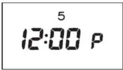
Fig. 2.4

Fig. 2.5

Fig. 2.6
Int Fig. 3

Fig. 3.1
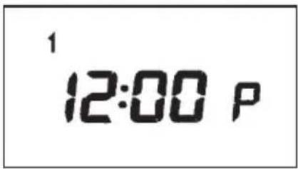

Fig. 3.3 Fig. 3.2

Fig. 3.4

Fig. 3.5

Int Fig. 4

Fig. 4.1

Fig. 4.2
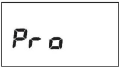
Fig. 4.3

Fig. 4.4
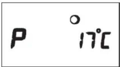
Fig. 4.5

Fig. 4.6
Int Fig. 5

Fig. 5.1

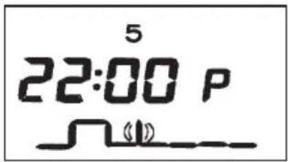
Fig. 5.3 Fig. 5.2
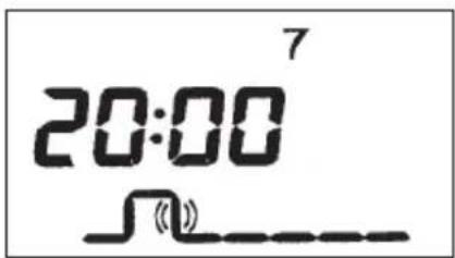
Fig. 5.17

Int Fig. 5
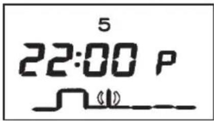
Fig. 5.18
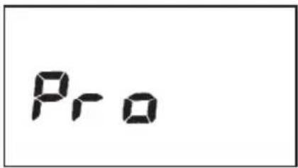
Fig. 5.19
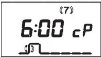
Fig. 5.20

Fig. 5.21

Fig. 5.22

Fig. 5.23
Int Fig. 5, 6

Fig. 5.24

Fig. 6.1

Int Fig. 7
7 Front casing on the room thermostat
8 Retaining cams
9 Mounting plate
10 Fixing holes
Fig. 7: Installation
13 Vaillant THERMOcompact
Fig. 9: Wiring
12 Bornier VRT-PZA
13 Thermotop/Thermocompact
Fig. 9: Schéma de raccordement
12 Klemmenstrook VRT-PZA
13 Klemmenstrook Vaillant Thermocompact
14 On/off analog switch
15 12/24-hours switch
Fig. 10: Back panel of the thermostat
12b Languettes
- VRT-PZA
- 2 TEMPERATURE SELECTOR
- 3 DISPLAY
- 4 PARTY KEY
- 5 DAY KEY
- 6 TIME KEY
- 7 CHANGE-OVER KEY
- 8 NIGHT-TIME TEMPERATURE KEY
- 9 BLOCK KEY
- 10 PROGRAMMING KEY
- 11 SETTING KEY
- 12 SETTING KEY
- A OPERATING INSTRUCTIONS - 1 APPLICATION (FIG. 1, P. 3)
- 1.1 OPERATING CONDITIONS
- 1.2 POSSIBILITIES FOR ENERGY SAVING LIMITING THE ROOM TEMPERATURE
- LOWERING THE ROOM TEMPERATURE
- EXTENDING THE DROP PERIODS
- VENTILATE BRIEFLY BUT THOROUGHLY
- KEEP THE ROOM THERMOSTAT CLEAR
- FULLY OPEN THE RADIATOR VALVES
- A OPERATING INSTRUCTIONS - 2 OPERATING MODE - NOTES ON PROGRAMMING (FIG. 1, 2)
- 2.1 SETTING THE OPERATING MODE
- 2.2 GENERAL NOTES ON PROGRAMMING
- A OPERATING INSTRUCTIONS - 3 SETTING THE TIMER (FIG. 1, 3)
- 3.1 READING THE TIME
- 3.2 SETTING THE DAY OF THE WEEK AND THE TIME
- A OPERATING INSTRUCTIONS - 4 SETTING THE ROOM TEMPERATURES (FIG. 1, 4)
- 4.1 SELECTING THE DAYTIME TEMPERATURE
- 4.2 INDICATING THE NIGHT-TIME TEMPERATURE
- 4.3 ALTERING THE NIGHT-TIME TEMPERATURE
- A OPERATING INSTRUCTIONS - 5 PROGRAMMING HEATING PERIODS (FIG. 1, P. 3, 5)
- 5.1 INDICATING THE HEATING PROGRAMME
- 5.2 INDICATE THE HEATING PROGRAMME
- A OPERATING INSTRUCTIONS - 5 PROGRAMMING HEATING PERIODS (FIG. 1, 5)
- 5.3 BASIC PROGRAMME
- 5.4 ENTERING HEATING PERIODS
- 5.5 EXAMPLE FOR ENTERING THE HEATING PERIOD
- 5.6 DELETING A HEATING PERIOD
- 5.7 SIMULTANEOUSLY PROGRAMMING OR COPYING RESP. HEATING PERIODS FOR SEVERAL DAYS
- B INSTALLATIONS INSTRUCTIONS - 6 SPECIAL OPERATING CONDITIONS (FIG. 1, 6)
- 6.1 PARTY OPERATION
- 6.2 SUMMERTIME OPERATION, FROST PROTECTION
- 6.3 OPERATION IN THE CASE OF A POWER FAILURE
- 6.4 OPERATION IN THE CASE OF A LONG-TERM POWER FAILURE
- B INSTALLATIONS INSTRUCTIONS - 7 SETTING THE FLOW TEMPERATURE
- B INSTALLATIONS INSTRUCTIONS - 8 INSTALLATION (FIG. 7)
- 8.1 WARNING
- 8.2 POSSIBLE USE
- 8.3 PUMP SETTING
- 8.4 INTERFERENCE SUPPRESSION
- 8.5 POSITIONING
- 8.6 INSTALLATION SEQUENCE
- A INSTALLATIONS INSTRUCTIONS - 9 ELECTRICAL CONNECTION (FIG. 8, 9, 10)
- CONNECTION TO THE THERMOCOMPACT/COMBICOMPACT
- PLEASE NOTE
- B INSTALLATIONS INSTRUCTIONS - 10 INITIAL TAKING INTO OPERATION(FIG. 10)
- 10.1 CHECK OPERATION
- THE FOLLOWING INSTRUCTIONS DETAILED NOTES MUST BE CARRIED OUT IN
- 10.2 ON/OFF ANALOG (CONTINUOUS) CONTROL
- B INSTALLATIONS INSTRUCTIONS - 10 INITIAL TAKING INTO OPERATION (FIG. 10)
- 10.3 12 H/24 H READING
- 10.4 MAKE THE ROOM THERMOSTAT READY FOR OPERATION
- B INSTALLATIONS INSTRUCTIONS - 11 TECHNICAL DATA
- INT FIG. 7
Brand : VAILLANT
Model : VRT PZA
Category : Thermostat