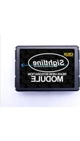
RVCPR-66 - Unknown CRUX - Free user manual and instructions
Find the device manual for free RVCPR-66 CRUX in PDF.


| Product Type | Vehicle Radio Replacement Interface |
| Model | RVCPR-66 |
| Brand | CRUX |
| Compatible Vehicles | Select Chrysler, Dodge, Jeep, RAM vehicles (check fitment guide) |
| Power Input | 12V DC (vehicle electrical system) |
| Standby Current Draw | < 5 mA |
| Dimensions (W x H x D) | Approx. 4.5 x 1.5 x 0.8 in (115 x 38 x 20 mm) |
| Weight | Approx. 0.2 lbs (90 g) |
| Main Functions | Retains factory features: steering wheel controls, amplifier, backup camera, etc. |
| Outputs | Pre-amp audio outputs (6-channel), video output for backup camera |
| Inputs | Vehicle-specific harness connector, aftermarket radio harness |
| Installation Method | Plug-and-play with included harnesses, no cutting wires |
| Programming Required | Sometimes required via DIP switches or auto-detect |
| Included Accessories | Main module, wiring harness, antenna adapter (if applicable), manual |
| Operating Temperature | -40°F to 185°F (-40°C to 85°C) |
| Warranty | 1 year limited warranty |
| Certifications | CE, RoHS |
Frequently Asked Questions - RVCPR-66 CRUX
User questions about RVCPR-66 CRUX
0 question about this device. Answer the ones you know or ask your own.
Ask a new question about this device
Download the instructions for your Unknown in PDF format for free! Find your manual RVCPR-66 - CRUX and take your electronic device back in hand. On this page are published all the documents necessary for the use of your device. RVCPR-66 by CRUX.
USER MANUAL RVCPR-66 CRUX
2013 - 2015 911 (from Software Version 4.xx ONLY)
2014 - 2015 Boxster (from Software Version 4.xx ONLY)
2008 - 2015 Cayenne
2014 - 2015 Cayman (from Software Version 4.xx ONLY)
2010 - 2015 Panamera
Disclaimer: Depending on the HW version of your PCM system, this product may not support some versions. Please contact us for more information.
APPLICATION NOTES:
ONLY FOR VEHICLES WITHOUT
FACTORY REAR-VIEW CAMERA
WORKS FOR:
PCM 3.1 NAVIGATION RADIOS
PCM 3.0 NAVIGATION RADIOS
(Cayenne Only)
Internal DVD player will not be able to be watched while in motion.
Contact Tech Support for more information.
PARTS INCLUDED
(1) PR-66 CAN Interface Module
(1) PR-66 40-Pin T-Harness
(1) C-02 Camera
(1) 15ft Extension
(1) Instruction Sheet
SAFETY PRECAUTIONS
- Please read through the entire instruction manual before starting any of the installation procedures.
- We recommend disconnecting the negative side of the battery until ready to code the vehicle.
- Do not install any of the main modules near any major components or near the HVAC system, as placing items near the HVAC may cause damage or overheating to the vehicle or interface.
- We recommend not disconnecting any of the air bag connections behind the dash panels.
- This product is under Crux's 1 year manufacturer's warranty. Warranty may be voided in the case where the device shows proof of being opened or improper extreme force.
TECH SERVICES
All our products are manufactured under strict quality control. Each device is being tested before shipment. If nevertheless do occur problems or if you have technical questions, contact us directly:
Crux Interfacing Solutions Tech Support
1 (855) 822-1348 (Mon - Fri - 9:00 AM - 5:00 PM) Time Pacific
INSTALLATION OVERVIEW
![graph TD A["40-PIN (male plug)"] --> B["8-PIN (male plug)"] C["40-PIN (female plug)"] --> B D["TO FACTORY HARNESS"] --> E["YELLOW / VIDEO SIGNAL CAMERA INPUT"] B --> F["TAP BLACK/WHITE/GREEN/REVERSE WIRE"] B --> G["CAMERA GROUND"] B --> H["CAN INTERFACE"] B --> I["CAMERA (INCLUDED)"] style A fill:#f…](/content/2026/06/1249723/images/f119e977ad11c6ff0440e18554735dc43adae4835e92ba1165134f25e03d503a.jpg)
DIP SWITCHES OVERVIEW
Make sure to set dip switch number 6 to "ON" position.
For the RVC feature, you will only need to set dip switch "2" to ON.

VIDEO IN-MOTION

NO
VIDEO
IN-MOTION

CONNECTING THE INTERFACE
Follow these steps to properly install interface module.
Step 1 - Remove the factory radio to gain access to the factory 40-Pin connector. Remove the factory 40-Pin connector. Your radio face may differ.

Step 2 - Prior to connecting the interface, we recommend taping the 4 wires necessary to power the module. Connect the 4 loose wires from the harness to the 4 designated wires on the factory 40-Pin connector.
Factory Connector Pin Assignments
| COLOR | DESCRIPTION | TAP PIN |
| RED = | 12V CONSTANT | 15 |
| BLACK = | GROUND | 12 |
| ORANGE/BROWN = | CAN-LOW | 9 |
| ORANGE/PURPLE = | CAN-HIGH | 11 |
Crux holds no liability for the vehicle wiring color codes and pin configuration. As there may be changes by the vehicle manufacturer that we may not be aware of. Installer must verify this information prior to being installed.

INSTALLING THE INTERFACE
Follow these steps to properly install the interface module. Prior to installing the interface we recommend disconnecting the negative side of the battery. use a resistor lead if needed, as the manufacturer does not suggest disconnecting the battery cable.
Step 3 - Connect the module to the 8-Pin connectors on the provided T-Harness.
Make sure your connection is firmly inserted into the module.
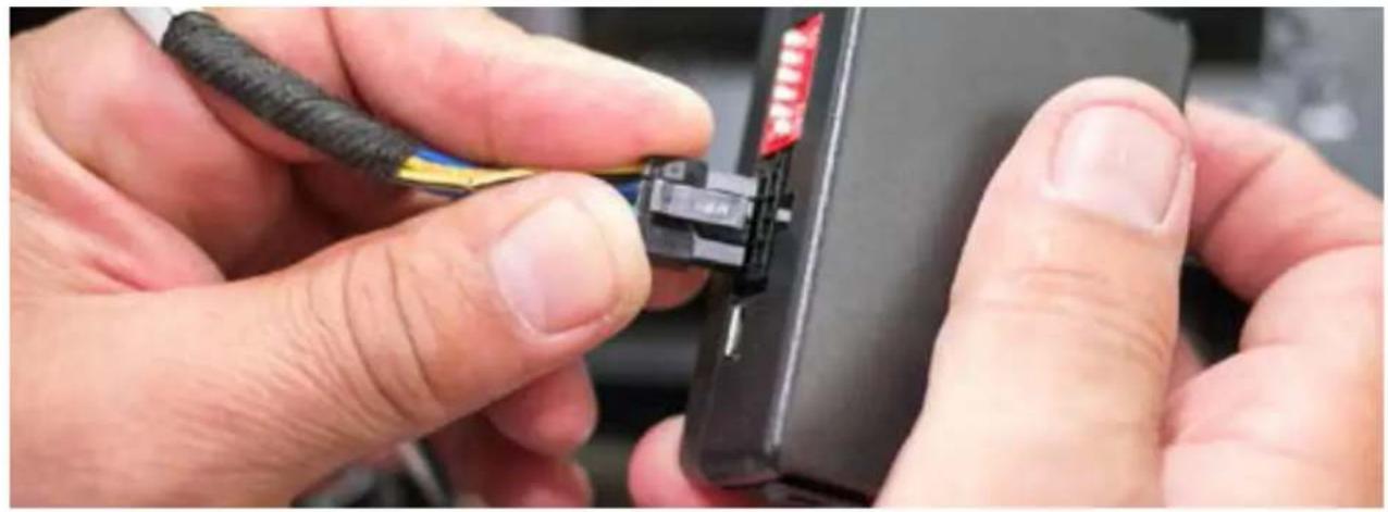
Step 4 - Mate the 40-Pin T-harness connections, to the factory harness and to the back of the factory radio.
After connecting the module, set dip switch number "6" to the "ON" position. (Latch locks and releases harness)

CODING THE VEHICLE
In order to activate the Rear-View Camera feature, the installer must CODE the car first.
Step 5 - While listening to the FM Source, place dip switch number "2" to the "ON" position on the module.
The screen will power off and begin to reset.

DIP SWITCH DESCRIPTION LOCATED ON THE CAN MODULE.

DIP 1 = Video In-Motion Enable
DIP 2 = Factory Rear-View Camera
DIP 3 = Code Rear-View Cam w/ White Wire
DIP 4 = Code Park Assist w/ White Wire
DIP 5 = Not Used
DIP 6 = Can-Bus Termination
LED INDICATORS
DATALINK LED:
Blinking = BUS Detected.
OFF = Power Down/ Sleep mode.
POWER LED:
ON = Power On
OFF = Power OFF
After each change of the DIP switch settings, we recommend powering down the module, then restarting the vehicle.
TECH TIP:
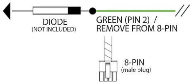
IN THE CASE THAT THE VEHICLE IS MANUAL TRANSMISSION, THE INTERFACE WILL NOT PROVIDE YOU THE REVERSE OUTPUT. YOU WILL NEED TO TAP THE CARS REVERSE LIGHT TO THE GREEN WIRE FROM THE 8-PIN CONNECTOR ON THE MODULE.
Step 1. Remove the GREEN wire (Pin 2) from the 8-Pin connector.
Step 2. Connect the GREEN wire to the REVERSE light from the car. We recommend using a DIODE when connecting.
Step 3. Make sure nothing is populating Pin 2 on the 8-Pin connector.
TO REVERSE LIGHT
CATHODE TOW ARDS LIGHT
CODING THE VEHICLE
In order to activate the Rear-View Camera feature, the installer must CODE the car first.
Step 6 - With the T-Harness and interface module properly connected, turn the ignition to the "ON" position.
Wait for the head unit to power on then proceed to the following steps.
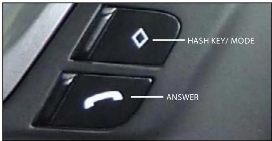
On the left side of the steering wheel:
- Press and Hold both the "Hash Key" and "Answer" buttons for 10 approx. 10 seconds.
During the coding process, the Red and Blue LED will begin to flash.
- After the head unit has begun to reset, release both buttons.
The Red and Blue LED's will glow solid to identify the coding has been completed.
Step 7 - With the interface coding successful, you will be able to enter the menu structure and see "Rear-View Camera" in the menu structure.

Step 8 - Now you may proceed to installing the Rear-View Camera. Make sure to use the 8-Pin connector for REVERSE and GROUND for the camera. (See Installation Overview) Note: The vehicle display offers a Zoom + and Zoom - option, this interface does not support this option.
![graph TD A["CAN INTERFACE"] --> B["8-PIN (male plug)"] B --> C["TAP BLACK/ CAMERA GROUND"] C --> D["WHITE/ ALTERNATIVE CODING"] D --> E["GREEN/ REVERSE WIRE"] E --> F["CAMERA (INCLUDED)"] F --> G["YELLOW / VIDEO SIGNALCAMERA INPUT"]](/content/2026/06/1249723/images/cbef4ea4fe2f4e728546b5d4becfbfb6ba0e5f385aa02b9d12cfcfde07320168.jpg)
DECODING THE VEHICLE REAR-VIEW CAMERA
In the case where you need to decode the aftermarket rear-view camera input, please do the following:
Step 9 - With the T-Harness and interface module properly connected, turn the ignition to the "ON" position.
Wait for the head unit to power on then proceed to the following steps.
On the left side of the steering wheel:
-
Press and Hold both the "Hash Key" and "End Call" buttons for 10 approx. 10 seconds. (See page 5 for HASH Key) During the coding process, the Red and Blue LED will begin to flash.
-
After the head unit has begun to reset, release both buttons. The Red and Blue LED's will glow solid to identify the coding has been completed.

To activate the Video In-Motion please do the following.
Option 1 - Permanent Activation: By activating dip switch number "1" to the "ON" position the Video In-Motion is permanently active.
Note: Having the Video In-Motion active will not affect the GPS performance.
SWITCH DIP 1 TO THE "ON" POSITION FOR PERMANENT ACTIVATION
CAN INTERFACE

CODING AND DECODING OPTIONS
You must code the park assist in order to retain.
CODING THE PARK ASSIST
Its necessary to code the vehicle in order to activate the factory Park-Assist, if equipped from the factory.
Step 1 - With the T-Harness and interface module properly connected, turn the ignition to the "ON" position. Wait for the head unit to power on then proceed to the following steps.
On the steering wheel:
-
Press and Hold both the "BACK" and "ANSWER" buttons for 10 approx. 10 seconds. During the coding process, the Red and Blue LED will begin to flash.
-
After the head unit has begun to reset, release both buttons. The Red and Blue LED's will glow solid to identify the coding has been completed.
DECODING THE PARK ASSIST
In case you may need to remove the interface, here is how you decode the Park-Assist.
Step 1 - With the T-Harness and interface module properly connected, turn the ignition to the "ON" position. Wait for the head unit to power on then proceed to the following steps.
On the steering wheel:
-
Press and Hold both the "BACK" and "END CALL" buttons for 10 approx. 10 seconds. During the coding process, the Red and Blue LED will begin to flash.
-
After the head unit has begun to reset, release both buttons. The Red and Blue LED's will glow solid to identify the coding has been completed
THE PARK ASSIST OPTION WILL NO LONGER BE AVAILABLE ON THE MENU.
USING THE WHITE WIRE TO ACTIVATE THE REAR-VIEW CAMERA AND/OR PARK ASSIST
Aside from coding the vehicle using the Steering Wheel Controls, you can code the vehicle using the loose WHITE wire on the CAN module and dip switches 3 and 4.
Dip 3 = Rear-View Camera Enable
Dip 4 = Park Assist Enable
Step 1 - With the T-Harness and interface module properly connected, turn the ignition to the "ON" position. Wait for the head unit to power on then proceed to the following steps.
On the CAN module:
-
Set dip switches 3 and 4 on the CAN module ON or OFF (Depending on Coding or Decoding)
-
Place 12V on the WHITE wire for approx. 5 Seconds. During the coding process, the Red and Blue LED will begin to flash.
-
After the head unit has begun to reset, release both buttons. The Red and Blue LED's will glow solid to identify the coding has been completed.
THE PARK ASSIST ND REAR-VIEW CAMERA OPTION WILL BE AVAILABLE ON THE MENU.

After coding is complete, you must wait 60 seconds until trying to code or decode the vehicle again.
COMPATIBLE RADIOS
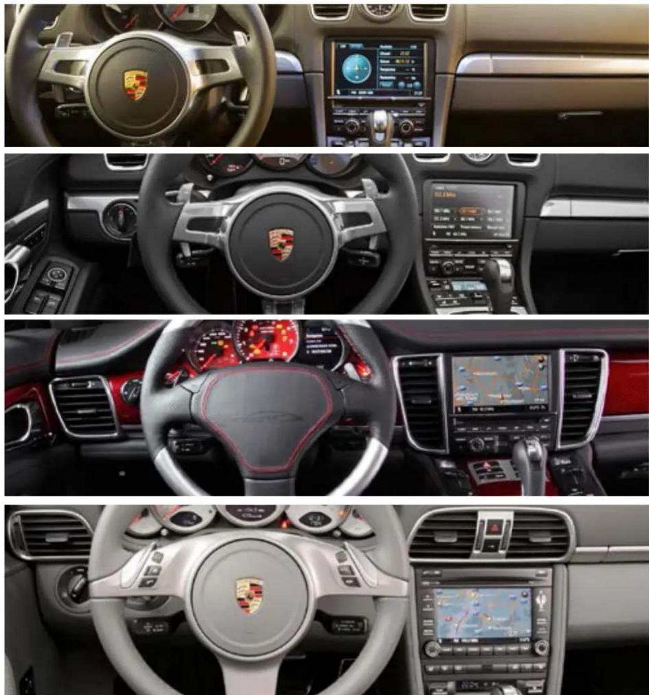


- APPLICATION NOTES
- ONLY FOR VEHICLES WITHOUT
- FACTORY REAR-VIEW CAMERA
- WORKS FOR
- PCM 3.1 NAVIGATION RADIOS
- PCM 3.0 NAVIGATION RADIOS
- (CAYENNE ONLY)
- PARTS INCLUDED
- SAFETY PRECAUTIONS
- TECH SERVICES
- DIP SWITCHES OVERVIEW
- CONNECTING THE INTERFACE
- INSTALLING THE INTERFACE
- CODING THE VEHICLE
- TECH TIP
- DECODING THE VEHICLE REAR-VIEW CAMERA
- STEP 9 - WITH THE T-HARNESS AND INTERFACE MODULE PROPERLY CONNECTED, TURN THE IGNITION TO THE "ON" POSITION
- ON THE LEFT SIDE OF THE STEERING WHEEL
- CAN INTERFACE
- CODING THE PARK ASSIST
- DECODING THE PARK ASSIST
Brand : CRUX
Model : RVCPR-66
Category : Unknown