
ACPBM-77Z - Unknown CRUX - Free user manual and instructions
Find the device manual for free ACPBM-77Z CRUX in PDF.

| Product Type | Smart-Play Integration Module |
| Brand | CRUX |
| Model | ACPBM-77Z |
| Compatibility | BMW vehicles with NBT infotainment system (2010-2016 models: 1,2,3,4,5,6,7 Series, X1,X3,X4,X5,X6, M2,M3,M4, i3) |
| LVDS Connection | 6-pin LVDS (not 4-pin) |
| Smartphone Compatibility | Android 8+ and Apple devices; wireless and wired (USB) connection |
| Video Inputs | Front camera (Smart-Play), Rear camera (OEM or aftermarket) |
| Audio Input | 3.5mm AUX input (vehicle's AUX) |
| Power Supply | 12V DC from vehicle harness |
| Trigger Output | +12V, 1A max (Pink wire for camera power) |
| Display Support | 6.5", 7", 8.8", 10.25" monitors (configurable via DIP switches) |
| Functions | Smart-Play integration, aftermarket rear view camera input, picture-in-picture with factory PDC, interactive lane lines, OSD menu, forced rear-view camera option |
| Controls | iDrive knob (High/Low), voice control, OSD menu |
| LED Indicators | Blue, Green, Red (must be solid for operation) |
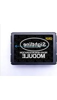
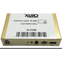
| Included Accessories | ACPBM-77Z module, Power/CAN harness, Vehicle harness, LVDS cable, 3.5mm to RCA adapter, Smart-Play interface module, microphone |
| Installation | Behind dashboard, requires removal of radio and LCD screen; detailed instructions provided |
| Operating Temperature | Not specified; typical automotive range (-20°C to 70°C estimated) |
| Certifications | Not specified |
Frequently Asked Questions - ACPBM-77Z CRUX
User questions about ACPBM-77Z CRUX
0 question about this device. Answer the ones you know or ask your own.
Ask a new question about this device
Download the instructions for your Unknown in PDF format for free! Find your manual ACPBM-77Z - CRUX and take your electronic device back in hand. On this page are published all the documents necessary for the use of your device. ACPBM-77Z by CRUX.
USER MANUAL ACPBM-77Z CRUX
- Smart-Play Integration system allows connection of Android and other devices to the iDrive infotainment system
- Control Apps using smartphone's voice control feature or the factory iDrive (High/Low) Knob
- Adds aftermarket rear view camera input.
- Forced rear-view camera option (only on vehicles with PDC button)
- Picture-in-picture mode combining after-market rear-view picture with factory parking sensor graphics.
- Interactive parking guide lines with calibration function.
- Simultaneous use of picture-in-picture factory parking sensor graphics and interactive lane lines
- Built-in on-screen display and setup.
- 1 trigger output (+12V max. 1A) for the camera power.
*NOTE: Android Phones must have a firmware version of 8 and above.
The vehicle needs to have a factory AUX input.*
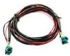
PARTS INCLUDED:

natural_image
Black rectangular electronic device with two small blue connectors and a red label (no visible text or symbols)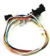
natural_image
Coiled electrical cable with multiple wires and connectors (no visible text or symbols)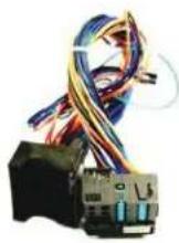
ACPBM-77Z Module Power/CAN Harness ACPBM-77Z Vehicle Harness
natural_image
Coiled black and red electrical connector with two green connectors at the end (no text or symbols visible)
natural_image
A black audio jack with three red and white cables (no text or symbols visible)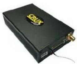
natural_image
Black electronic device with gold logo and USB port, no visible text or symbolsCRUX LVDS Cable 3.5mm to RCA Adapter Smart-Play Interface Module

natural_image
Black cord with earbuds and connector, isolated on white background (no text or symbols)Microphone
INSTALLATION DIAGRAM:

flowchart
graph TD
    A["ACPBM-77Z Module"] --> B["Back of Headunit"]
    B --> C["Vehicle Auxiliary Input (AUX input)"]
    C --> D["Back-Side of Factory LCD Screen"]
    D --> E["Aftermarket Crux LVDS Cable"]
    E --> F["+12V Switching Output 1 (Pink Wire)"]
    F --> G["Power/CAN Harness"]
    G --> H["ACPBM-77Z Vehicle Harness"]
    H --> I["Factory Harness"]
    I --> J["Smart Play Module"]
    J --> K["Wireless Adapter"]
    K --> L["USB Input"]
    L --> M["Smartphone Cable OR USB"]
    N["Female RCA to 3.5mm jack"] --> O["Mobile External Cable"]
    P["Microphone"] --> Q["Smartlink Cable"]
    Q --> R["Power/Video CRUX"]
    R --> S["+12V Switching Output 1 (Pink Wire)"]
    S --> T["Camera (RED)"]
    T --> U["+12V Switching Output 1 (Pink Wire)"]
    U --> V["Power/CAN Harness"]
    V --> W["ACPBM-77Z Vehicle Harness"]
    X["Back of Headunit"] --> Y["Pink factory LVDS Cable"]
    Y --> Z["ACPBM-77Z Vehicle Harness"]
DIP SWITCH SETTINGS:
Setting the DIP switches of the Interface Box.
DIPs 1 and 2 on the back of the interface-box is used to set the monitor size. DIP 3 must be set to OFF.
After each change of the DIP switch settings you have to execute a power reset of the Interface box!
| Vehicle/ navigation | Dip 1 | Dip 2 | Dip 3 |
| 6.5" monitor (ver.1) | OFF | OFF | OFF |
| 6.5" monitor (ver.2) | OFF | OFF | ON |
| 7" monitor (ver.1) | OFF | OFF | OFF |
| 7" monitor (ver.2) | OFF | ON | OFF |
| 8.8" monitor | ON | OFF | OFF |
| 10.25" monitor (ver.1) | ON | OFF | OFF |
| 10.25" monitor (ver.2) | ON | ON | OFF |
LED's of the interface-box

NOTE: Must have solid BLUE, GREEN, RED, LEDs for part to work..
OSD SETTINGS:
OSD Menu
Use the following buttons to enter the ACPBM-77Z OSD Menu:
NOTE: Must be in factory infotainment menu to trigger full OSD menu
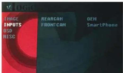
To ensure that Smart-Play works, make sure these input settings are in effect:
FRONTCAM (FVC) = SmartPhone
To retain the factory Back-Up Camera:
REARCAM (RVC) = OEM
To activate an aftermarket Back-Up Camera:
REARCAM (RVC) = ON

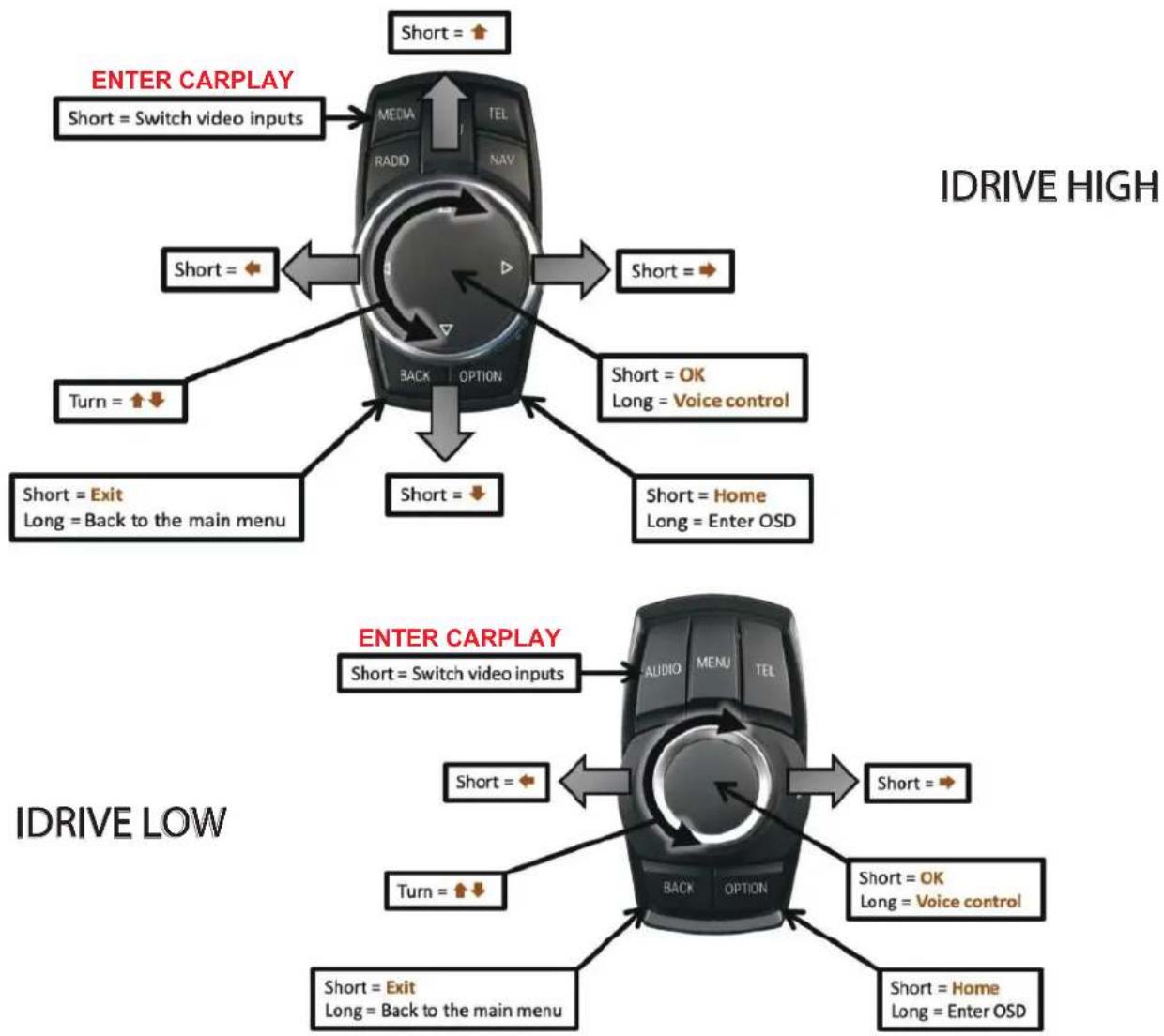
IDRIVE HIGH / IDRIVE LOW
| OSD-menu | Menu item | Setting | Description |
| OPTION | IDRIVE | LOW | Vehicles with iDrive Low control knob |
| HIGH | Vehicles with iDrive High control knob |
Controlling of the connected SMART-LINK module
The picture shows which functions of the connected SMART-LINK module can be executed by iDrive control panel. Once the FVC/SmartPhone input is activated the iDrive control panel action will execute the function described in the picture.
flowchart
graph TD
    A["IDRIVE HIGH"] --> B["Short = Switch video inputs"]
    B --> C["Short = ✓"]
    C --> D["Short = ✓"]
    D --> E["Short = ✓"]
    E --> F["Short = ✓"]
    F --> G["Short = ✓"]
    G --> H["Short = ✓"]
    H --> I["Short = ✓"]
    I --> J["Short = ✓"]
    J --> K["Short = ✓"]
    K --> L["Short = ✓"]
    L --> M["Short = ✓"]
    M --> N["Short = ✓"]
    N --> O["Short = ✓"]
    O --> P["Short = ✓"]
    P --> Q["Short = ✓"]
    Q --> R["Short = ✓"]
    R --> S["Short = ✓"]
    S --> T["Short = ✓"]
    T --> U["Short = ✓"]
    U --> V["Short = ✓"]
    V --> W["Short = ✓"]
    W --> X["Short = ✓"]
    X --> Y["Short = ✓"]
    Y --> Z["Short = ✓"]
    Z --> AA["Short = ✓"]
    AA --> AB["Short = ✓"]
    AB --> AC["Short = ✓"]
    AC --> AD["Short = ✓"]
    AD --> AE["Short = ✓"]
    AE --> AF["Short = ✓"]
    AF --> AG["Short = ✓"]
    AG --> AH["Short = ✓"]
    AH --> AI["Short = ✓"]
    AI --> AJ["Short = ✓"]
    AJ --> AK["Short = ✓"]
    AK --> AL["Short = ✓"]
    AL --> AM["Short = ✓"]
    AM --> AN["Short = ✓"]
    AN --> AO["Short = ✓"]
    AO --> AP["Short = ✓"]
    AP --> AQ["Short = ✓"]
    AQ --> AR["Short = ✓"]
    AR --> AS["Short = ✓"]
    AS --> AT["Short = ✓"]
    AT --> AU["Short = ✓"]
    AU --> AV["Short = ✓"]
    AV --> AW["Short = ✓"]
    AW --> AX["Short = ✓"]
    AX --> AY["Short = ✓"]
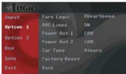
CONFIGURING THE TRIGGER OUTPUTS
You can configure the +12V trigger outputs in the OSD menu. The PINK wire (12V OUTPUT 1) in for the SMARTPLAY module. Power Out 2 is for the Cameras.

* = Recommended
| OSD-menu | Menu item | Setting | Description | |
| OPTION | POWER OUT 1 (PINK) | CAN | * | Smart-Play power onpower off |
| OFF | ||||
| POWER OUT 2 (GREEN) | CAN | * | +12V when the interface is on (red LED on) | |
| ACC | +12V when ignition is on | |||
| CAM | +12V when the rear-view camera input is activated | |||
| RGEAR | * | +12V when reverse gear is engaged | ||
| OFF | Trigger output deactivated | |||
Tip: We recommend for all cameras to use power out setting "CAN" or RGEAR and for Smart-Play, power out setting of "CAN"
Interactive Lane Lines
The ACPBM-77Z includes an Interactive Lane Lines function that is added to the aftermarket rear view camera. Use the OSD menu to activate this feature.

natural_image
Pure geometric lines forming a triangular shape with intersecting diagonal and horizontal segments (no text or symbols)| OSD Menu | Menu Item | Setting | Description |
| Option | RVC Lines | OFF | Dynamic lane lines deactivated |
| ON | Dynamic lane lines activated | ||
| Car Type | LOW | 5 Button | |
| HIGH | 7 Button |

SETTINGS FOR INPUT AND OPTIONS
| V. OGIC | ||
| INPUT | RVC | ON |
| OPTION | FVC | SmartPhone |
| OSD | ||
| INFO | ||
| EXIT | ||
| BACK | ||
| v LOGIC | ||
| INPUT | PARK LOGIC | PDC |
| OPTION | RVC GRAPHIC | LINES |
| OSD | POWER OUT 1 | CAM |
| INFO | POWER OUT 2 | ACC |
| EXIT | CAR TYPE | XG |
| IDRIVE TYPE | LOW | |
| VIM | OFF | |
| FACTORY RESET | ||
| BACK | ||
| OSD-menu | Menu item | Setting | Description |
| INPUT | FVC | OFF | No front camera/SMART-LINK connected |
| SMARTPHONE | Enables the " FRONT CAM" input and control for the SMART-LINK set | ||
| OPTION | PARK LOGIC | PDC | For vehicles with PDC button. Enabled while parking process and up to 20 km/h or together with PDC if existing |
| RGearOnly | Enabled while parking process | ||
| RGearSpeep | Enabled while parking process and up to 20 km/h | ||
| RGearTime | Enabled while parking process and up to 20 second | ||
| RVC GRAPHICS | PIP1 | OEM PDC display of the vehicle | |
| LINES Interactive lane lines activated | |||
Note: You can deactivate the enabled parking process by pressing the iDrive or by enabling other modes (e.g. radio). After deactivation you can't enable the parking process again until the vehicle is diving faster than 20km/h, the ignition is switched off and on or the PDC will be disabled and enabled again, if existing.
SETTINGS FOR OEM REAR-VIEW CAMERA
| OSD-menu | Menu item | Setting | Description |
| INPUT | RVC | OEM | If a factory rear-view camera is existing!The interface turns off, if PDC or reverse gear is enabled and it displays factory rear-view camera and/or PDC-display |
| OPTION | PARK LOGIC | PDC | For vehicles with PDC button. Enabled while parking process and up to 20 km/h or together with PDC if existing |
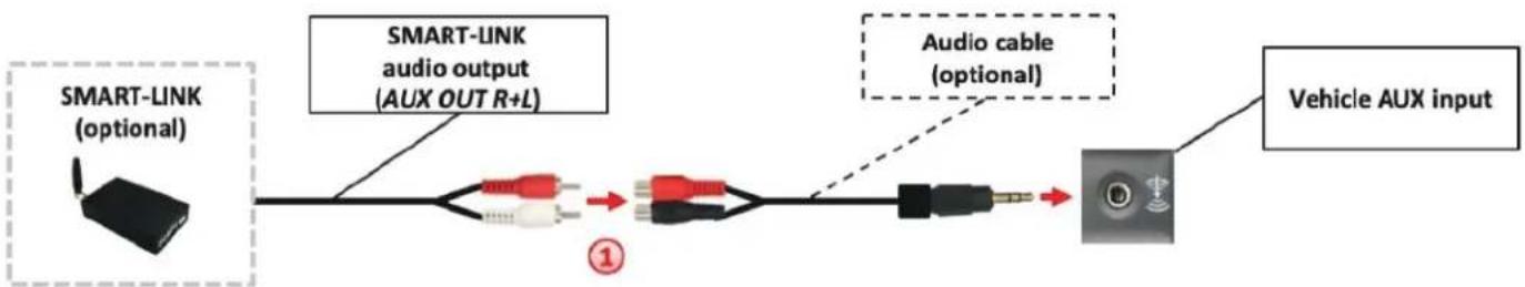
SMART-LINK AUDIO CONNECTIONS
flowchart
graph LR
    A["SMART-LINK (optional)"] --> B["SMART-LINK audio output (AUX OUT R+L)"]
    B --> C["Switch"]
    D["Audio cable (optional)"] --> E["Switch"]
    E --> F["Vehicle AUX input"]

By using an audio cable (sold separately), connect the audio output of the SMARTLINK module to the vehicle AUX input.
NOTE:
Make sure the audio source on the factory system is set to AUX mode (not AM/FM/Bluetooth). Also, if your smart-phone is set to automatically connect to your factory bluetooth, make sure you void the connection. One way is to forget the device (your vehicle) on your phone. This will avoid Smart-Play connection interferences. If you are using the wireless feature and notice degraded audio or video quality, switch to the wired alternative, for it is a higher quality connection, unlike bluetooth.
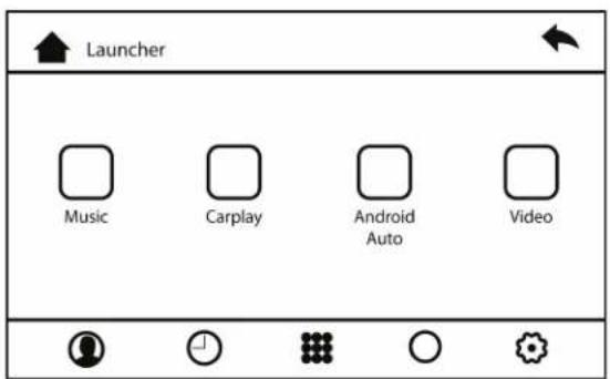
CONNECTING THE SMART-PLAY INTERFACE:
The ACPBM-77Z utilizes wireless technology for Apple devices/Android devices. If desired for wired connectivity, devices are required to be plugged in to the USB port using the smartphones OEM charger/data cable. The USB port on the ACPBM-77Z can be used to charge the apple device or play video or music from a USB thumb drive.
Using the ACPBM-77Z Input Selection
In the vehicle's Media menu, activate AUX Input to get the Smart-Play sound through the vehicles audio system. Press the 'BACK' button again for 3-5 seconds to go to the ACPBM-77Z AV mode.
A short press of the 'MEDIA' button will toggle through the video sources. Each short press will toggle to the next enabled input. If all inputs are enabled, the order will be:
Rear CAM > Video Input (Smart-Play) > Repeat...
To exit the Smart-Play menu, hold the 'Menu' button for 3-5 seconds

- Picture above shows the HOME screen of the Smart-Play interface. Music and Video is used in conjunction with a USB thumb drive plugged into the USB port.

- Go to the 'Settings' then 'Bluetooth' on your Apple device and connect to /CRUX Smart-Play_XXXX'
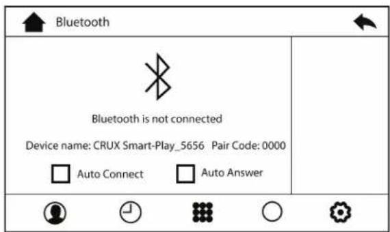
- Using the iDRIVE knob of the vehicle, navigate the cursor to the Bluetooth icon (scrolling right). Image above will appear on the screen the BT device name and pairing code (0000)

- Once the ACPBM-77Z has connected via Bluetooth, it will also connect to Wi-Fi automatically.

- Use the iDrive knob to navigate the cursor to the 'Back' button
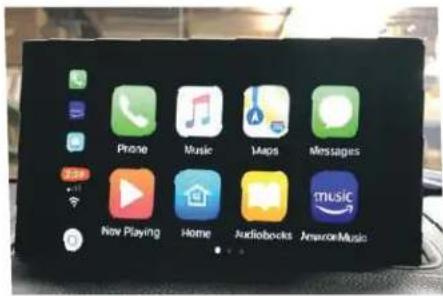
- Image above shows the 'Home Screen' once the smartphone is connected.
Display settings for Smart-Play
Adjust brightness, contrast, and saturation for a more defined image.
To get to the Display menu, scroll to the SETTING icon in the Smart-Play HOME menu, and select it.

Once in the SETTING menu, scroll to the Dlsplay submenu and adjust the brightness, contrast, and saturation to your desired values.

Interactive Lane Lines Settings
The height and width of the interactive lane lines can be set in the OSD menu. For this setting you must first activate the rear view camera level and push the "MENU" button for 2 seconds to activate the settings menu. With the rotation knob you can select the menu point "Line Height" to change the height of the interactive lane lines and with menu point "Line Width" the width of the lines. Click "Exit" to leave the settings menu.

Picture Settings
The camera picture can be set in the OSD menu. For this setting you must first activate the camera level and push the "MENU" button for 2 seconds to activate the settings menu. With the rotation knob you can select and change the "Brightness", "Contrast", "Saturation", Hue" and "Sharpness". Click "Exit" to leave the settings menu.

Note: The picture settings will be retained for every camera input separately.
OSD Settings
You can change the basic configurations of the interface in the OSD (on screen display).

| OSD Menu M | Menu Item | Setting | Description |
| OSD | POS. X 0-xxx | Horizontal position of the OSD | |
| POS. Y 0-xxx | Vertical position of the OSD | ||
| Size | Small Small OSD menu window | ||
| Large Large OSD menu windows | |||
| Osd TimeOut 2-20 | Time setting for automatic OSD shutoff | ||
| Info Version X.XX.XX Displays the current SW-version | |||
| Option 1 | Factory Reset | Reset to factory default settings | |

10 of 15
rev.05182022
INSTALLATION INSTRUCTIONS:
natural_image
Interior view of a car dashboard and backseat showing the front grille, grille, and dashboard controls (no visible text or symbols)- Installation is done behind the front panel.
natural_image
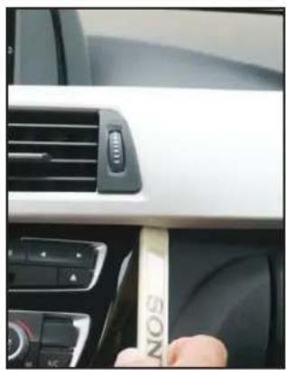
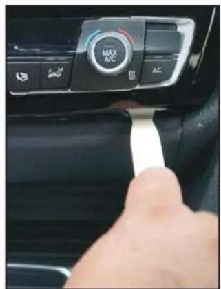
Close-up of a car interior showing the dashboard and air vent, with a hand inserting a beige card labeled 'SONS' (no readable text beyond label)- Remove the dashboard front panel. 3
natural_image
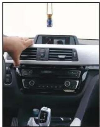
Interior view of a car dashboard with hand adjusting the grille and control panel (no visible text or symbols)Remove the front panel.
natural_image
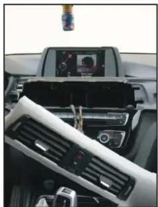
Interior view of a car dashboard with air vent, digital display, and camera (no visible text or symbols)- We must now remove the four screws behind the front panel.
natural_image
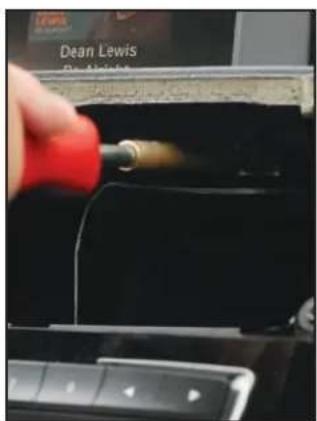
Close-up of a hand inserting a red cable into a car infotainment panel (no visible text or symbols)- Use a T-20 bit to remove these 4 screws.
natural_image
Close-up of a hand pressing down on a car's side panel with a white cable (no visible text or symbols)- Remove the panel below the A/C control.
natural_image
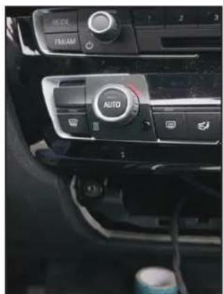
Interior view of a car dashboard with multiple controls and a central 'AUTO' button (no visible text or symbols beyond the branding)- Remove the two torques behind the panel.
natural_image
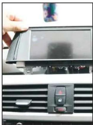
Close-up of a car's front panel showing the screen and control panel (no visible text or symbols)- Remove the LCD monitor. 9. Unplug
natural_image
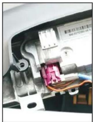
Close-up of an electrical component with visible wiring and a small internal structure (no readable text or symbols)the pink LVDS connector from behind the LCD monitor.
natural_image
Close-up of a car dashboard with visible wiring and control buttons, no text or symbols present.- Remove the A/C control panel.

natural_image
Close-up of a computer RAM module with visible socket and cable (no text or symbols)- Remove the two torques bracing the radio unit.
natural_image
Hand holding a computer drive chassis, showing internal components and ventilation slots (no visible text or labels)- Remove the radio unit.

natural_image
Hand holding a small metallic plastic component with visible internal structure, partially bound to exposed wiring (no text or symbols)- Remove the Quadlock connector from behind the radio.
natural_image
Hand holding a black electronic device with visible ports and wiring, next to a car dashboard (no readable text or symbols)- Insert the CRUX LVDS Cable into the LVDS OUT port on the ACPBM-77Z module.
natural_image
Close-up of a hand holding a black cable with red wires, next to a white electronic device (no visible text or symbols)- Funnel the CRUX LVDS cable from the radio cavity to the LCD screen cavity.

natural_image
Close-up of a hand holding an open car interior showing internal components and wiring (no visible text or symbols)- Connect the otherside of the CRUX LVDS Cable to the LVDS port on the LCD screen and place it to rest.

natural_image
Close-up of a hand holding a small electronic component with purple, blue, and black connectors (no visible text or symbols)- Funnel the Pink LVDS cable to the radio cavity and connect it to the LVDS IN port on the ACPBM-77Z module.

natural_image
Close-up of a hand holding a black plastic connector with blue and red wires, no visible text or symbols- Connect the male side of the ACPBM-77Z vehicle harness to the factory female Quadlock connector that was originally connected to the radio.
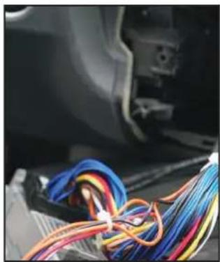
natural_image
Close-up of a car's electrical wiring with multicolored wires wrapped around it (no visible text or symbols)- Connect the female side of the ACPBM-77Z vehicle harness to the factory radio.

-
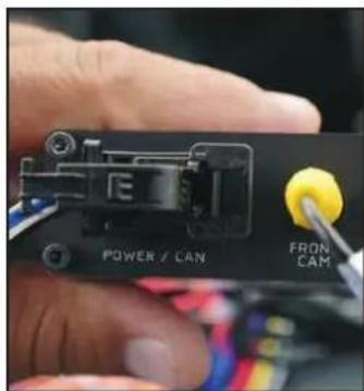
Plug the Video Out from the Smart-Play Power/Video harness into the FRONT CAM input on the module.
-
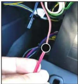
If installing an aftermarket back-up camera, plug the cameras video out to the REAR CAM input on ACPBM-77Z module. You will also need to power the camera for it to work. Use the PINK power output 1 wire provided on the power/CAN harness to do this. An image is displayed in step 23. If retaining an OEM camera, skip steps 22 and 23.
natural_image
Close-up of a hand holding a pink cable with wires, no visible text or symbols- Connect the RED camera power wire to the PINK power output 1 wire.
natural_image
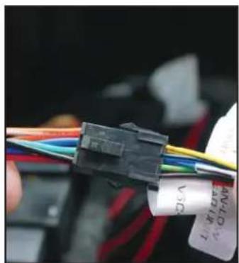
Close-up of a black plastic connector with multicolored wires and a white label (no readable text or symbols)- Connect the male 8-pin connector from the vehicle harness to the female 8-pin connector on the Power/CAN harness.
- Tap the RED ACC wire from the Power/Video harness to the green +12V output, from the previous step's 8-pin male connector.
natural_image
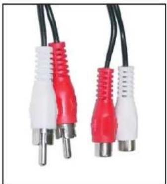
Close-up of two red and white audio/video cables with black leads (no text or symbols visible)- Connect the male audio RCA outputs from the Power/Video harness to the Female RCA-to-3.5mm cable.

natural_image
Close-up of a black mechanical component with a white cable inserted, showing a small internal component (no text or symbols visible)- Connect the 3.5mm jack from the convertor to the vehicle auxiliary input (AUX IN).

natural_image
Close-up of a car's rearview and side mirror showing the camera lens (no text or symbols visible)- Mount the microphone to a loca- 28 tion of your choice.
natural_image
Close-up of a hand holding a black audio jack connected to wires, with no visible text or symbols.Connect the 3.5mm microphone jack to the MIC input on the Power/Video harness.
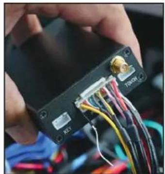
- Connect the Power/CAN harness to the POWER/CAN input on the ACPBM-77Z module.

natural_image
Hand holding a black electronic device with labeled ports (RGB, LIVS, UART) and wiring visible outside (no readable text or symbols)- Connect the 4-pin connector from the Power/CAN harness to the UART port on the Smart-Play module.
natural_image
Close-up of hands holding a black electronic device with visible wiring and connectors (no readable text or symbols)- Connect the Power/Video harness to the POWER/VIDEO port on the Smart-Play module.
natural_image
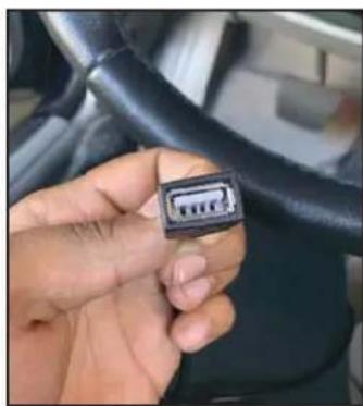
Close-up of a hand holding a black connector pin on a car interior (no visible text or symbols)- Route the USB cable to a desired location and connect it to your smartphone's lightning cable.

natural_image
Close-up of a black electronic device with illuminated ports and wiring (no visible text or symbols)- Test the communication. Turn on the ignition and check if LEDs are on.
- Check the OSD settings and makesure they match those on the next page. Test the Back-Up camera. Put gear in reverse and check for rear camera image on screen. Go to Smart-Play mode and test for functionality. Once the cameras and Smart-Play validation is complete, mount the ACPBM-77Z and Smart-Play modules, reinstall all the components to their original set-up.
VEHICLE APPLICATIONS:
BMW
| 2015 – 2016 | i3* | 2014 – Up | 4 Series |
| 2016 | M2 | 2012 – Up | M3 / 3 Ser ies |
| 2016 | X1 | 2014 – Up | 2 Series |
| 2010 – Up | X3 | 2012 – Up | 1 Series |
| 2014 – Up | X4 | 2010 – Up | 5 Series |
| 2014 – Up | X5 | 2011 – Up | 6 Series |
| 2015 – Up | X6 | 2008 – 2015 | 7 Series |
| 2015 – Up | M4 |

This product is designed to work for the NBT infotainment system only
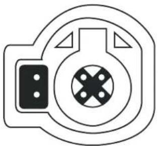
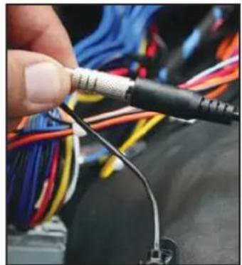
natural_image
Pure mechanical component diagram without any text, numbers, or symbolsThis product is compatible with the 6 PIN LVDS not the 4 PIN LVDS


- PARTS INCLUDED:
- INSTALLATION DIAGRAM:
- DIP SWITCH SETTINGS:
- LED's of the interface-box
- OSD SETTINGS:
- OSD Menu
- Controlling of the connected SMART-LINK module
- CONFIGURING THE TRIGGER OUTPUTS
- Interactive Lane Lines
- NOTE:
- CONNECTING THE SMART-PLAY INTERFACE:
- Using the ACPBM-77Z Input Selection
- Display settings for Smart-Play
- Interactive Lane Lines Settings
- Picture Settings
- OSD Settings
- INSTALLATION INSTRUCTIONS:
- VEHICLE APPLICATIONS:
Brand : CRUX
Model : ACPBM-77Z
Category : Unknown