
TND4004 - Camera Elmo - Free user manual and instructions
Find the device manual for free TND4004 Elmo in PDF.


| Product Type | Document Camera / Visual Presenter |
| Image Sensor | 1/3 inch CMOS |
| Maximum Resolution | 1920 x 1080 (Full HD) |
| Optical Zoom | 12x |
| Digital Zoom | 8x |
| Focus Type | Auto & Manual |
| Frame Rate | 30 fps (1080p) |
| Video Output | HDMI, USB 2.0 |
| Still Image Capture | JPEG (via USB) |
| Lighting | Built-in LED lamps |
| Dimensions (W x D x H) | 280 x 200 x 450 mm (approx.) |
| Weight | 2.5 kg (approx.) |
| Power Supply | AC 100-240V, 50/60 Hz (adapter included) |
| Power Consumption | 20W (typical) |
| Compatible Software | Windows, Mac (via USB) |
| Cleaning Instructions | Use a soft, dry cloth; avoid liquids |
| Safety Warning | Keep away from water and heat sources |
| Spare Parts Availability | Contact Elmo support for replacement bulbs and cables |
| Warranty | 2 years (depending on region) |
Frequently Asked Questions - TND4004 Elmo
User questions about TND4004 Elmo
0 question about this device. Answer the ones you know or ask your own.
Ask a new question about this device
Download the instructions for your Camera in PDF format for free! Find your manual TND4004 - Elmo and take your electronic device back in hand. On this page are published all the documents necessary for the use of your device. TND4004 by Elmo.
USER MANUAL TND4004 Elmo
The lightning flash with arrowhead symbol, within an equilateral triangle, is intended to alert the user to the presence of uninsulated "dangerous voltage" within the product's enclosure that may be of sufficient magnitude to constitute a risk of electric shock to persons.

The exclamation point within an equilateral triangle is intended to alert the user to the presence of important operating and maintenance (servicing) instructions in the literature accompanying the appliance.
CAUTION
- Do not use any power supply other than specified.
WARNING
TO REDUCE THE RISK OF FIRE OR ELECTRIC SHOCK, DO NOT EXPOSE THIS APPLIANCE TO RAIN OR MOISTURE.
* The CAUTION label is attached on the back of camera.
INFORMATION
This equipment has been tested and found to comply with the limits for Class A digital device, pursuant to Part 15 of the FCC Rules. These limits are designed to provide reasonable protection against harmful interference when the equipment is operated in a commercial environment. This equipment generates, use, and can radiate radio frequency energy and, if not installed and used in accordance with the instruction manual, may cause harmful interference to radio communications. Operation of this equipment in a residential area is likely to cause harmful interference in which case the user will be required to correct the interference at his own expense.
USER-INSTALLER CAUTION: Your authority to operate this FCC verified equipment could be voided if you make changes or modifications not expressly approved by the party responsible for compliance to Part of the FCC Rules.
IMPORTANT SAFETY INSTRUCTIONS
- Read these instructions.
- Keep these instructions.
- Heed all warnings.
- Follow all instructions.
- Do not use this apparatus near water.
- Clean only with dry cloth.
- Do not block any ventilation openings, install in accordance with the manufacture's instructions.
- Do not install near heat sources such a radiators, heat registers, stoves or other apparatus (including amplifiers) that produce heat.
- Only use attachment/accessories specified by the manufacturer.
- Unplug this apparatus during lighting storms or when unused for long periods of time.
- Refer all servicing to qualified personnel. Servicing is required when the apparatus has been damaged in any way, such as power-supply cord or plug is damaged, liquid has been spilled or objects have been fallen onto the apparatus, the apparatus has been exposed to rain or moisture, does not operate normally, or has been dropped.
1. Appearance view


Unit : mm (inch)
2. Specifications
| Model | TND4004 |
| Power source | DC 12V (DC 11V-35V) or AC 24V (AC 15V-27V) 60Hz ± 0.5Hz |
| Power consumption | Approx. 3.5W |
| Pick-up device | 1/3" Color interline-transfer CCD |
| Effective picture element | 768 (H) X 494 (V) |
| Scanning area | 4.88mm (H) X 3.66mm (V) |
| Scanning system | 2:1 interlaced |
| Scanning frequency | LL : 15.75kHz (H), 60Hz (V) / INT : 15.734kHz (H), 59.94Hz (V) |
| Sync. system | Line-Lock/Internal (Factory-set at Line-Lock) |
| Resolution | 470TV lines (H), 350TV lines (V) |
| S/N ratio | More than 48dB |
| Standard illumination | 150 lx (F1.4 under incandescent lamp) |
| AGC | Built-in |
| Sens-up | Provided (Factory-set at OFF) |
| White balance | ATW/AWC/manual/Preset (Factory-set at ATW) |
| Backlight control (BLC) | Provided (Factory-set at OFF) |
| Iris level adjustment | Provided (volume adjustment) |
| VIDEO OUT terminal | VBS 1V (p-p) 75Ω |
| Lens | F 1.4, f = 2.8 ~ 6mm |
| Angle of view | Horizontal : 47° (TELE) ~ 96° (WIDE)Vertical : 36° (TELE) ~ 72° (WIDE) |
| Iris | Auto |
| Appearance color | Main body : White |
| Dimensions | Cover : BlackDiameter : 116mm (4.6") Height : 106mm (4.2") without protruded part |
| Weight | 0.5 kg (1.1 lbs) |
| Ambient temperature | -10°C ~ +50°C (14°F~122°F) |
| Ambient humidity | 30% ~ 90% |
Note : Weight and dimensions are approximate.
Design and specifications are subject to change without prior notice.
3. Name and Function of Each Part
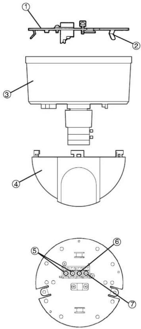
① Metal fitting
For mounting on the ceiling or wall.
② Hook (3 locations)
For temporarily fixing the main body.
③ Main body
The main body of a camera section.
④ Dome cover
A protective cover for the lens section.
⑤ AC/DC power terminal
Connect this to the AC24V 60Hz or DC12V power supply.
⑥
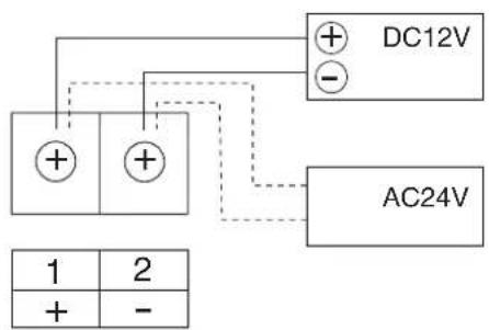
VIDEO OUT terminal
Connect coaxial cable to a monitor TV, etc.
⑦ Ground terminal
Connect this to the ground wire of the power supply cord.
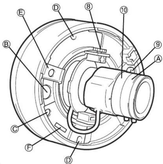
⑧ Tilt lock screw
For locking the tilt after adjusting the image up/down direction.
⑨ Pan lock screw
For locking the pan after adjusting the image right/left direction.
⑩ Zoom ring
For adjusting the image size.
Ⓐ Focus ring
For adjusting the focus.
⑧ PUSH button
- Vertical sync. phase adjustment
To adjust the vertical sync. phase when using two or more Line-Lock cameras, press the PUSH button Ⓑ
(▲or ( ) until images stop rolling.
However, it should be noted that this adjustment is not valid when the select switch is in such positions as WB1: L, WB2: L and WB3: H.
- Manual white balance selector
When the white balance selector is set to MANU (shift change) in Ⓗ on the next page, the white balance can be adjusted by using the PUSH button. This mode will prove effective under shooting conditions with little variation in color temperature.
* When the white balance selector is set to MANU (shift change), the vertical sync. phase can not be adjusted.
© ALC LEVEL
For adjusting the image brightness.
(D) Main body mount screws (2 pcs)
Screws located for mounting the main body to the metal fitting.
Caution: Both screws must be tighten to prevent the camera from falling.
⑤ Reinforce board
A board rotating together with the camera part.
* This board may interfere with the selector switch depending on the set pan direction. Slide the board to avoid the interference with the selector switch. After this sliding, be sure to
⑤ Selector switch (details)
a. White balance selector
Combination of the switch 1, 2, and 3, the following adjustments are available:
- ATW (AWB)
The camera adjusts the white balance by automatically following the color temperature change within the pull-in color temperature range.
The pull-in color temperature range is from approx. 2500K to approx. 9500K.
- AWC/HOLD (AWB)
AWC
This is auto white balance mode with no limits, such as pull-in frame.
HOLD
The white balance in the state can be held by switching the mode to HOLD after the white balance is attained by AWC.
This mode is effective for imaging conditions with little color temperature change.
- Manual White Balance (MWB)
The color temperature can be shifted by pressing the PUSH button. For the information of switch shift, refer to P. 4 Ⓑ.
- Preset (MWB)
Color temperature can be selected from among four different color temperatures.

(This figure shows the setting before shipment from our factory.)
| WB1 | WB2 | WB3 | |
| L | L | L | ATW |
| L | H | L | AWC |
| L | H | H | HOLD |
| L | L | H | Manual |
| H | L | L | Manual (Fixed 3200k) |
| H | L | H | Manual (Fixed 4200k) |
| H | H | L | Manual (Fixed 4700k) |
| H | H | H | Manual (Fixed 6300k) |
b. INT/LL switch
- INT (internal) control switch
When the internal synchronization is used, set the switch to the INT side.
- LL (Line-Lock) control switch
Matching the vertical synchronization with the power frequency is called the line-lock.
When two or more cameras are switched by the video switcher to a monitor TV, the vertical sync. phase can be locked with the power frequency, and a stable vertical sync. is obtained without being disturbed at the time of switching.
Line-lock is operative only when the AC 24V power supply is connected.
Caution:
- The camera is synchronized to the power frequency of 60Hz ± 0.5Hz covering a normal fluctuation of the power frequency.
The camera may not compensate for large fluctuation caused by power generated by an engine generator. etc.

flowchart
graph TD
    A["Monitor TV"] -->|To DC 12V power supply or To AC 24V power supply| B["Output"]
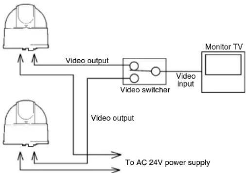
flowchart
graph TD
    A["Monitor TV"] --> B["Video input"]
    B --> C["Video switcher"]
    C --> D["Video output"]
    D --> E["To AC 24V power supply"]
    F["Camera 1"] --> C
    G["Camera 2"] --> C
-
It takes about 10 seconds or more to obtain a stable synchronization after the power is turned on. This is necessary to stabilize the camera against the power noise.
-
When DC 12V power supply is used, set the switch to the INT side.
c. BLC (Back Light Control) switch
In case the back lighting is too bright to shoot the main object clearly, set this switch to ON position.
d. SENS-UP switch
To increase the sensitivity, set this switch to ON position.
4. How to Set Up
4-1 How to Install and Adjust
Recommended mounting surface is wood or dry wall.
(1) Make a round hole of 70mm OD (2.76") to the mounting surface where the camera is to be mounted. (Refer to Fig.1)

(Fig. 1)
(2) Attach coaxial cable and power cord to the POWER & VIDEO terminal on the metal fitting. (Refer to Fig. 2)
Refer to Page 11 for preparation of the coaxial cable.
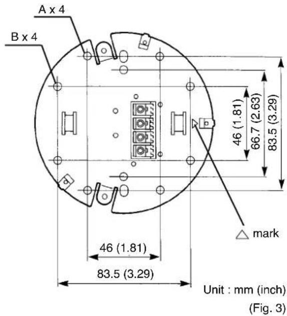
(3) Mark four mounting holes to the mounting surface with pencil for the metal fitting as follows:
-
Dimensions: Refer A or B from Fig. 3.
-
To mount on the ceiling, point mark on the metal fitting toward the object. (Refer to Fig. 3)
-
To mount on the wall, point the mark on the metal fitting facing downward. (Refer to Fig. 3)
(4) To mount on a wood surface, use four #8x 1.5" screws to secure the metal fitting.
To mount on a dry wall surface, drill four 3/16" holes first and insert 3/16" anchors then secure the metal fitting with four #8x1.5" screws.
All hardware is optional.
■ To directly mount on the surface, make sure to use four screws to ensure firm locking.
■ Be careful not to damage the coaxial or power cables.
If it is impossible to make a 70mm hole to the surface, use an optional metal fitting for the wall (EB-413B).

(5) Remove the dome cover from the main body. Remove the dome cover by turning it counterclockwise (arrow direction) (Fig. 4).

(6) Mount the body to the metal fitting. Match the positioning mark on the main body with the mark on the metal fitting, and thrust the main body toward the metal fitting. Be sure that the main body engages with the hooks (3 locations) of the metal fitting (Fig. 5). Confirm that the main body is in parallel with the metal fitting when viewed from the side (Fig. 6).

* If not, the camera may come off from the metal fitting and drop.

(7) Fasten the main body mount screws (2 pcs) attached with the main body to lock the main body on the metal fitting (Fig. 7).
* Confirm that notches and are matched with the main body mount screws. If not, loosen the pan lock screw, turn the base, and match the notches and with these screws.
If the notches are not matched with these screws, a screwdriver cannot catch the screws, and the body cannot be locked.
* Be sure to fasten the main body mount screws.

(8) While watching the monitor, adjust the image direction.
· Right/left direction (Fig. 8)
Loosen the pan lock screw, turn the base right and left, and adjust the right/left direction. After setting the right/left direction, tightly fasten the pan lock screw
* If the pan lock screw is not tightly fastened, the base may turn when the dome cover is mounted.
* Be careful not to drop the pan lock screw.
· Up/down direction (Fig. 9)
Loosen the tilt lock screw, and adjust up/down direction.
After setting the up/down direction, fasten the tilt lock screw.
* Manually fasten the tilt lock screw. If fastened with pliers or the like, the tilt lock screw may be broken.


(Fig. 9)
(9) Adjust the optical axis (Fig. 10).
Correct the tilt of the image with the optical axis ring.
* Be sure to hold the optical axis ring when making this correction.

(10) Adjust the angle of view with the zoom ring (Fig. 11).

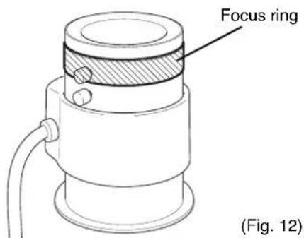
(11) Adjust the focus with the focus ring (Fig. 12).
* Adjust the focus after adjusting the angle of view.
(12) Match the "I" mark on the lens with the recessed portion of the camera holder (Fig. 13).
* Be sure to match them, or the dome cover may not be mounted in same lens position.

Recessed part of the camera holder
(13) Mount the dome cover on the main body. Match the mark on the dome cover with that on the base, and turn the dome cover clockwise (arrow direction) until it is clicked (Fig. 14).
* If these marks are not matched, the dome cover cannot be mounted.

Dome cover
(Fig. 14)
4-2 How to Connect the Cables
(1) Prepare the coaxial cable end as shown (Fig. 15).
(2) Connect the coaxial cable and power cables to the terminal strip.
Insert the core underneath of the appropriate locking washer fitting, and fasten the screw.
Secure the shielding wire to the coaxial cable fixing metal fitting with the screws (Fig. 16).
* If you wish to run the coaxial cable outside of the wall or ceiling, use optional metal fittings for wall (EB-413B).
(3) Connect cables to the monitor TV and power source.


(Fig. 16)
4-3 Notes in Use
- Use this unit indoors. Do not mount it outdoors.
- When the cover needs cleaning, wipe it with a soft cloth.
Do not use alcohol, thinner or the like.
- If a part of the image is exposed to strong light, such as light bulb, the auto iris may be activated to darken the screen. In this case, change the direction or adjust the iris with the ALC adjust volume.
PRECAUTIONS FOR USE AND INSTALLATION
* Never aim the camera at the sun.
Never aim or point the camera at the sun even if you are not shooting.
* Do not shoot intense light.
Strong light such as a spot light on the image plane will cause blooming or smear. When strong light comes into the image plane, vertical stripes may appear on it. However, this does not mean that the camera is defect.
* Take precautions when handling a camera.
Do not drop your camera, or give it a strong shook or vibration. This may cause camera to malfunction.
* Do not touch internal parts.
Be sure not to touch the internal parts. This may cause to electrical shock.
* Do not let the camera get wet.
Install the camera at the place where it will not get wet.
Should it gets wet, turn off the power immediately and contact your dealer.
* Install your camera where no video noise appears. When camera cables have been laid near electric wires or television receivers, a noise may interfere the image. If noise occurs, relocate cables or reinstall equipment.
* Check the ambient temperature and humidity.
Avoid using camera in areas where temperature is consistently hotter or colder than the specified range (See Specifications chart below) or poor image quality or damaged parts may occur. Precautions should also be taken to avoid areas of high humidity.
* Should you notice any trouble.
If any trouble occurs while you are using the camera, turn off the camera and contact your dealer. Failure to do so may cause damage to the camera.
* The socket-outlet should be installed near the equipment and should be easily accessible.
* Do not place this video product on an unstable cart, stand, tripod, bracket, or table. The video product may fall, causing serious injury to a child or adult, and serious damage to the appliance. Use only with stand, tripod, bracket, or table recommended by the manufacturer, or sold with the video product. Any mounting of the appliance should follow the manufacturer's instructions, and should use a mounting accessory recommended by the manufacturer.
* This video product should be operated only from the type of power source indicated on the marking label. If you are not sure of the type of power supply to your location, consult your appliance dealer or local power company.
* Power-supply cords should be routed so that they are not likely to be walked on or pinched by items placed upon or against them, paying particular attention to cords at plugs, screws, and the point where they exit from the appliance.
* Do not overload power supply and extension cords, as this can result in a risk of fire or electric shock.
* Never push objects of any kind into this video product through openings as they may touch dangerous voltage points or short-out parts that could result in a fire or electrical shock. Never spill liquid of kind on the video product.
* When replacement parts are required, be sure the service technician has used replacement parts specified by the manufacturer or that have the same characteristics as the original parts. Unauthorized substitutions may result in fire, electric shock or other hazards.
* Upon completion of any service or repairs to this video product ask the service technician to perform safety checks to determine that video product is in proper operating condition.

ELMO CO., LTD.
6-14, Meizen-cho, Mizuho-ku, Nagoya, 467-8567 Japan
OVERSEAS SUBSIDIARY COMPANIES
ELMO Mfg. Corp.
1478 Old Country Road,
Plainview, NY 11803-5034
U.S.A.
Tel. 516-501-1400
Fax. 516-501-0429
E-mail:elmo@elmousa.com
Web:http://www.elmousa.com/
ELMO Canada Mfg. Corp.
44 West Drive, Brampton,
Ontario, L6T 3T6,
Canada
Tel. 905-453-7880
Fax. 905-453-2391
E-mail:info@elmocanada.com
Web:http://www.elmocanada.com/
ELMO (Europe) G.m.b.H.
Neanderstr. 18
40233 Dusseldorf,
Germany
Tel. 0211-376051-53
Fax. 0211-376630
E-mail:elmoeurope@AOL.com
Web:http://www.elmo.de/
6X1NSBA02 Printed in CHINA


- CAUTION
- WARNING
- INFORMATION
- IMPORTANT SAFETY INSTRUCTIONS
- Appearance view
- Specifications
- Name and Function of Each Part
- How to Set Up
- 4-1 How to Install and Adjust
- 4-2 How to Connect the Cables
- 4-3 Notes in Use
- PRECAUTIONS FOR USE AND INSTALLATION
- ELMO CO., LTD.
- OVERSEAS SUBSIDIARY COMPANIES
- ELMO Mfg. Corp.
- ELMO Canada Mfg. Corp.
- ELMO (Europe) G.m.b.H.
Brand : Elmo
Model : TND4004
Category : Camera