
CC431E - Camera Elmo - Free user manual and instructions
Find the device manual for free CC431E Elmo in PDF.

| Product Type | Camera Control Unit (CCU) |
| Brand | Elmo |
| Model | CC431E |
| Dimensions (W x H x D) | 3.35" x 1.57" x 6.14" (85 mm x 40 mm x 156 mm) |
| Weight | 0.86 lbs (390 g) |
| Power Supply | DC 12V ± 0.5V, Current: 800 mA minimum |
| Power Consumption | 310 mA (with MN43H camera head) |
| Video Output | VBS 1.0 V(p-p) (BNC), NTSC; Y/C separation (S-Video) |
| Sync System | Internal/External (automatic switching) |
| AGC (Automatic Gain Control) | OFF / ON / SENS UP (+6 dB) |
| White Balance Modes | AUTO / SET / MANU |
| Electronic Shutter | Auto, 1/60s to 1/10000s, Synchronized Scan |
| External Sync Input | VBS 1.0 V(p-p) (BNC), NTSC, 75Ω unbalanced |
| Operating Temperature | 14°F to 104°F (-10°C to +40°C) |
| Operating Humidity | Less than 90% |
| Connectors | CAMERA terminal, DC IN 12V, EXT SYNC, S-VIDEO, VIDEO, REMOTE (RS232C), IRIS |
| Compatible Camera Heads | MN43H, QN42H, QN42HL, CN43H, UN43H (with internal switch setting) |
| Compliance | FCC Part 15 Class A, Canadian ICES-003 |
| Cleaning Instructions | Use soft dry cloth; avoid benzene, alcohol, thinner, household detergents |
| Spare Parts / Accessories | Optional lenses, camera cables (EMC series), IRIS extension cable |
Frequently Asked Questions - CC431E Elmo
User questions about CC431E Elmo
0 question about this device. Answer the ones you know or ask your own.
Ask a new question about this device
Download the instructions for your Camera in PDF format for free! Find your manual CC431E - Elmo and take your electronic device back in hand. On this page are published all the documents necessary for the use of your device. CC431E by Elmo.
USER MANUAL CC431E Elmo
Thank you for purchasing the ELMO camera control unit CC431E. To use the camera properly, carefully read this operation manual before use. After reading the manual, we suggest you keep it in a convenient place for quick reference.
COMPONENTS
(1) Camera control unit (CCU)
(2) Accessory: Operation manual
NOTE: Camera head, Lens, AC/DC adapter, camera cable and video cable are option.
INFORMATION
This equipment has been tested and found to comply with the limits for a Class A digital device, pursuant to Part 15 of the FCC Rules. These limits are designed to provide reasonable protection against harmful interference when the equipment is operated in a commercial environment. This equipment generates, uses and can radiate radio frequency energy and, if not installed and used in accordance with the instruction manual, may cause harmful interference to radio communications.
Operation of this equipment in a residential area is likely to cause harmful interference in which case the user will be required to correct the interference at his own expense.
USER-INSTALLER CAUTION: Your authority to operate this FCC verified equipment could be voided if you make changes or modifications not expressly approved by the party responsible for compliance to Part 15 of the FCC rules.
This Class A digital apparatus complies with Canadian ICES-003.
Read the following safety precautions carefully before using this product. These instructions contain valuable information on safe and proper use that will prevent harm and damage to the operator and other persons. Make sure that you fully understand the following details (indications, graphic symbols) before proceeding to the remaining sections in this manual.
Indication definitions
| Indication | Meaning |
 Warning Warning | This indicates the existence of a hazard that death or catastrophic bodily injury*1 may result from improper use. |
 Caution Caution | This indicates the existence of a hazard that bodily injury*2 or property damage*3 may result from improper use. |
*1: Catastrophic bodily injury means loss of eyesight, burns (high and low tempered), shock, fracture, poisoning, etc. which leaves a sequela and require hospitalization or prolonged treatment.
*2: Bodily injury means injuries, burns and electric shock which does not require hospitalization or prolonged treatment.
*3: Property damage means extended harm to home, household effects, domesticated animals, and pets.
Graphic symbol definitions
| Symbol | Meaning |
 | "Indicates a prohibited action that must not be carried out. The actual prohibited action is indicated in the symbol or nearby graphically or described in text. |
 | "Indicates a mandatory action that must be carried out. The actual instruction is indicated in the symbol or nearby graphically or described in text. |
Warning

- Stop operation immediately when any abnormality or defect occurs.
Use during an abnormal condition; such as emitting smoke, burning odors, damage from dropping invasion of foreign objects, etc. may cause fire and/or electric shock. Be always sure to disconnect the power plug from the electrical outlet (socket) at once and contact your dealer.

- Avoid installing in a shower room or a bathroom.
This may cause fire and/or electric shock.

- Do not operate in places with possibility of becoming wet.
This may cause fire and/or electric shock.

- Do not repair, disassemble and/or modify by yourself.
This may cause fire and/or electric shock. Be always sure to contact your dealer for internal repair, check and cleaning of the product.

- Use the specified power supply.
Otherwise, a fire or an electric shock may occur.

- Don't place things or materials on the unit.
Ingress of foreign materials such as metallic things and liquid into the unit may cause a fire or an electric shock.

- Do not put the product in an unstable, slanting and/or vibrated place. Drop and/or fail of the product may cause injury.

- Do not touch the power cord or other connection cables during a thunderstorm. This might cause electric shock.
Caution

- Note the following instructions when installing.
- Do not put an inflammable material on the product.
- Do not put the product on an Inflammable material such as carpet or blanket.
- Do not block a vent hole.
- Do not put the product in a narrow space, since the heat generated from the product may be difficult to emanate.
If you do not follow the above, the heat generated by the product may cause fire.

- Do not put the product in direct sunshine and/or high temperature.
The temperature inside the product may cause fire.

- Avoid setting in humid, smoky, vaporized or dusty places. A fire or an electric shock may occur in such places.
This may cause fire and/or electric shock.

- Do not point the lens directly at the sun and/or intensive light such as direct sunlight, etc.
Focusing of the light may cause injury of eye and/or fire.

- Do not put the product in your mouth or swallow any parts.
This may cause suffocation and/or injury.

- Ask your dealer to perform a periodical check and internal cleaning (approx. once every five years).
Dust inside the product may cause fire and/or trouble. For check and cleaning cost, please consult your dealer.
Disclaimer
We disclaim any responsibility and shall be held harmless for any damages or losses incurred by the user in any of the following cases:
- Fire, earthquake or any other act of God; acts by third parties; misuse by the user, whether intentional or accidental; use under extreme operating conditions.
- Malfunction or non-function resulting in indirect, additional or consequential damages, including but not limited to loss of expected income and suspension of business activities.
- Incorrect use not in compliance with instructions in this instruction manual.
- Malfunctions resulting from misconnection to other equipment.
- Repairs or modifications made by the user or caused to be made by the user and carried out by an unauthorized third party.
- Notwithstanding the foregoing, ELMO's liabilities shall not, in any circumstances, exceed the purchase price of the product.
Copyright and Right of Portrait
There may be a conflict with the Copyright Law and other laws when a customer uses, displays, distributes, or exhibits an image picked up by a television camera without permission from the copyright holder. Please also note that transfer of an image or file covered by copyright is restricted to use within the scope permitted by the Copyright Law.
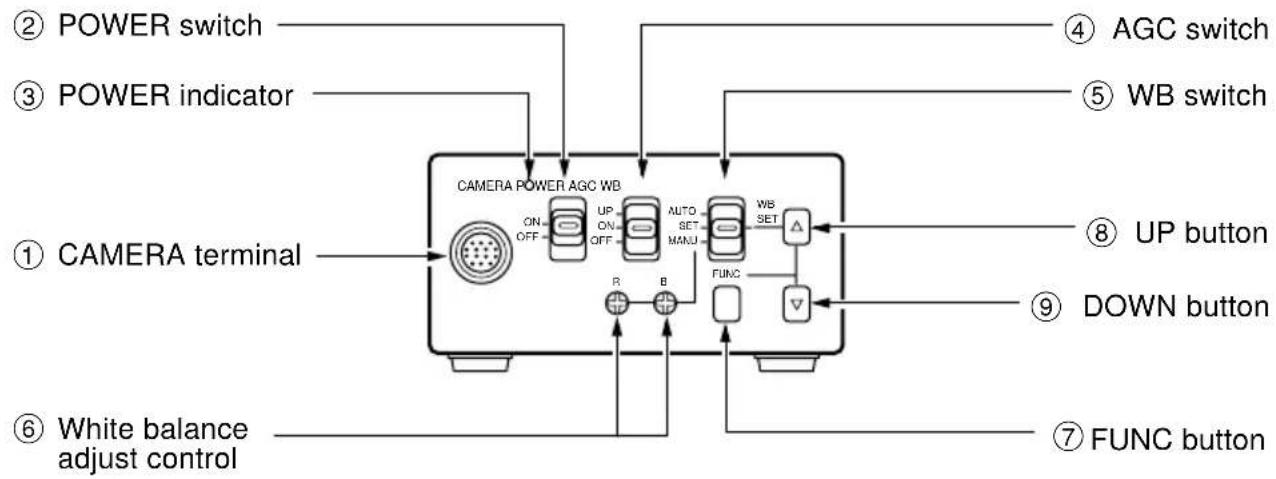
PART NAMES AND FUNCTIONS
Camera Control Unit (CCU)
flowchart
graph TD
    A["CAMERA POWER AGC WB"] --> B["ON/OFF"]
    B --> C["UP ON/OFF"]
    C --> D["AUTO SET MANU"]
    D --> E["WBS SET"]
    E --> F["△"]
    F --> G["DOWN button"]
    H["POWER switch"] --> I["① CAMERA terminal"]
    J["POWER indicator"] --> K["② POWER switch"]
    L["④ AGC switch"] --> M["⑤ WB switch"]
    N["⑥ WHITE balance adjust control"] --> O["⑦ FUNC button"]
① CAMERA terminal Connects to the camera head.
② POWER switch Turns on and off the camera control unit.
③ POWER indicator Lights up when the power is turned on.
④ AGC switch Selects the gain mode. (AGC OFF/AGC ON/SENS UP)
⑤ WB switch Selects the white balance mode. (MANU/SET/AUTO)
⑥ White balance adjust control Adjusts the R gain and B gain with the white balance mode set to MANU by the WB switch ⑤.
⑦ FUNC button Determines the setting indication contents when the setting menu is displayed on the screen.
⑧ UP button Selects the setting item when the setting menu is displayed on the screen. (When the WB switch ⑤ is set to SET, pressing the UP button for more than 2 sec. activates the white balance SET operation.)
⑨ DOWN button Selects the setting item when the setting menu is displayed on the screen.
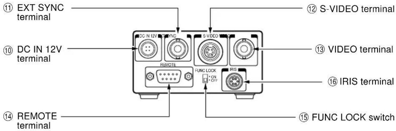
⑩ DC IN 12V terminal Accepts a DC power supply (12V).
⑪ EXT SYNC terminal Accepts an external sync signal to synchronize the camera output signal with external signal.
⑫ S-VIDEO terminal Connects terminal to S input terminal of a monitor or a VCR, etc.
⑬ VIDEO terminal Connects terminal to video input terminal of a monitor or a VCR, etc.
Used at the same time with the S-VIDEO terminal.
⑭ REMOTE terminal Controls the functions with RS232C.
⑮ FUNC LOCK switch Locks the switches and control on the front panel. When the FUNC LOCK switch is set to ON, all settings except for the POWER switch ② and the file item of the screen setting menu.
⑯ IRIS terminal Connect when using an automatic iris lens (with CN43H/CN42H camera head).
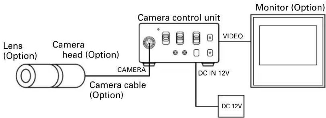
CONNECTION
Example of Standard Connection
DC power supply (Option)
Cautions on Connection
- When connecting or disconnecting the camera cables (for the camera head and camera control unit), always turn off the power switch of the camera control unit first. If not, the camera head may be damaged.
- When connecting the camera, always turn off the power of the camera control unit and any other equipment connected.
① Remove the camera head protection cover and mount a lens (option).
② Connect the camera head and the camera control unit with the camera cable (option).
③ Connect the VIDEO (or S-VIDEO) terminal of the camera control unit to a video input terminal of a monitor, etc.
④ Connect a DC power supply (12V) to the DC IN 12V terminal of the camera control unit.
- For DC power supply connecting to DC IN 12V terminal, use UL listed and/or CSA approved ungrounding type AC adaptor with the specifications described below.
Power supply voltage: DC12V ± 0.5V
Current rating: More than 800 mA
Ripple voltage: Less than 50 mV(p-p)
Connector: HR10A-7P-4S (Hirose)
Pins 1, 2: e, Pins 3, 4: d
Connection on CCU Back Panel
The figure below shows the back panel connection terminals of the camera control unit.
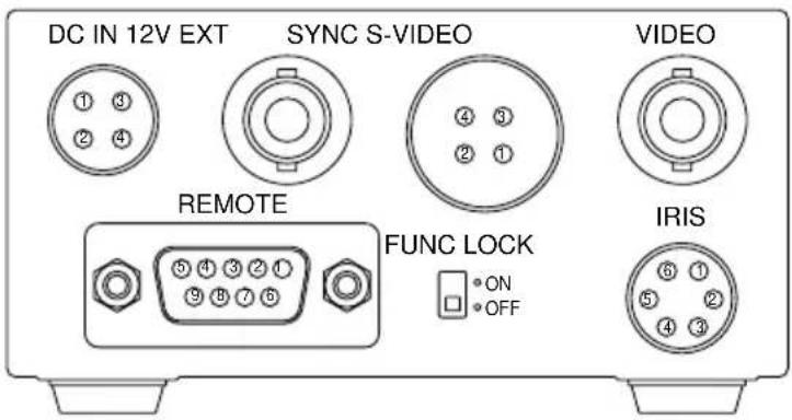
Connector Pin Assignments
DC IN 12V
| 1 | +12V |
| 2 | +12V |
| 3 | GND |
| 4 | GND |
S-VIDEO
| 1 | GND |
| 2 | GND |
| 3 | Y |
| 4 | C |
REMOTE
| 1 | NC |
| 2 | TXD |
| 3 | RXD |
| 4 | DSR |
| 5 | GND |
| 6 | DTR |
| 7 | CTS |
| 8 | RTS |
| 9 | NC |
IRIS
| 1 | NC |
| 2 | VIDEO |
| 3 | GND |
| 4 | +12V |
| 5 | GND |
| 6 | NC |
* When using the REMOTE terminal, please consult with your dealer.
• Using the auto-iris lens
The following table shows the IRIS terminal when using the auto-iris (EE) lens.
Table 1
| IRIS Connector Terminal No. | Signal | Rated |
| 1 | — | |
| 2 | Video signal | 0.8 ± 0.1Vp-p |
| 3 | GND | |
| 4 | Power (DC) | + 12V (less than 50mA) |
| 5 | (GND) | |
| 6 | — |
The IRIS connector used for the IRIS terminal: HR10A-7P-6P of HIROSE ELECTRIC CO., LTD.
- EE lens
The IRIS extension cable (optional) is usable for the EE lens. Use the connector HR10A-7P-4P of HIROSE when the IRIS extension cable is selected. For connections, follow the instruction below.
When the IRIS extension cable is used under the right condition, the cable automatically converts to connection for the EE lens in Table 1.
EE lens connector HR10A-7P-4P
- Power (+)
- GND
- Video signal
- Unconnected or ground
Notes:
- Current consumption must be 50 mA or less.
- Avoid an incorrect connection or short-circuit.
USING CAMERA CONTROL IN FIXED POSITION
The camera control unit can be directly mounted by using M3 screws if the four rubber feet are removed on bottom of the control unit. When mounting directly as described above, do not use longer screws. If the screws enter by more than 5 mm from the control unit mounting surface, they will cause a short-circuit inside the control unit. For details of screw hole locations, refer to “PROFILE” of the camera control unit.
HOW TO USE THE CAMERA
Turn on the POWER switch on the camera control unit and adjust the lens iris and focus while observing a picture on the monitor screen. To obtain the best picture quality, perform various settings.
AGC (Automatic Gain Control)
AGC functions "OFF", "ON" or "UP" can be selected on the screen menu. Generally, the camera is used with the AGC set to OFF, but when increased camera sensitivity is required, it is set to ON. When more sensitivity is required, "UP" is selected. With the AGC ON, the camera sensitivity approximately doubles, and with the UP selected the sensitivity approximately doubles again, but noise will also increase. We recommend you increase intensity of the lighting to obtain good pictures.
The AGC measurement area is the same as that used for "AREA". Refer to "AREA (Measurement Area)".
White Balance
A white balance adjustment is necessary to obtain pictures with correct color tone. This camera allows you to select the white balance adjustment of "AUTO", "SET", and "MANU". With the AUTO mode selected, the camera adjusts the white balance automatically. Most of shooting will be made in the AUTO mode. The color temperature applicable to this camera is about 2500 to 7000K.
| AUTO | SET | MANU | |
| Outline | Camera automatically measures object color temperature and adjusts the white balance. | Adjust white balance by pressing “UP” button on the camera control unit while shooting a white object. | Adjust R (red) and B (blue) levels on the control unit while shooting a white object. |
| Features | Automatically traces variations of color temperature and adjusts the white balance. | Measurement accuracy is higher than AUTO mode. This mode is effective when shooting under less variations of color temperature. | Measurement accuracy is higher than SET mode. This mode is effective for users desiring specific color temperature, also effective when shooting under least variations of color temperature. |
| Notes | Under poor illumination, white balance may not be corrected. | Adjustment will be made by viewing monitor or vector scope. |
(1) White balance adjustment in modes other than AUTO
(1.1) White balance adjustment in SET mode
① Set the WB switch to "SET" position.
② Shoot a white object to fill entire screen and press the UP button (▲) for about 2 sec.
③ When the white balance adjustment completes, the letters "WB SET" blinking at the upper right of the screen changes to "WB OK" and then turns off. If the "WB NG" is displayed, it shows the white balance is out of the adjustment range. This is caused in the white object is not shot or the video level is set too high or too low even if the white object is shot. Shoot the white object or set the video level correctly.
Note:
- With the screen menu displayed, the UP button is used for moving the cursor or modifying the data. To activate the SET mode by pressing the UP button, turn off the screen menu.
(1.2) White balance adjustment in MANU mode
① Set the WB switch to "MANU" position.
② Shoot the white object and adjust the white balance by adjusting the white balance adjust controls "R" and "B" with the screwdriver while observing the monitor or vector scope.
FUNC (Function Lock)
The FUNC LOCK switch protects settings even if a switch is accidentally pressed after setting. When the FUNC LOCK switch is ON, only the following functions are available.
POWER switch (ON/OFF)
FILE (A/B) in menu
Settings will not be changed even if the other switches are operated. In the menu screen, all except FILE and END are displayed in black letters (white when the FUNC LOCK switch is OFF) and "FUNCTION LOCK ACTIVE" blinks to indicate that the FUNC LOCK switch is ON.
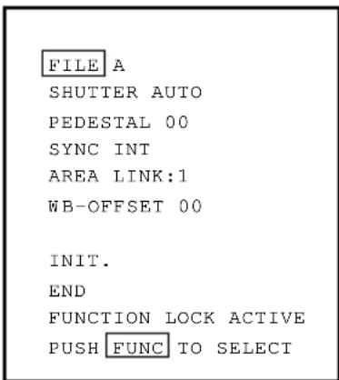
Setting while monitoring the menu on the monitor screen is possible. Following seven items can be set.
① Scene file
② Electronic shutter (AUTO/MANUAL), backlight correction
③ Pedestal level
④ Phase matching in external synchronization (horizontal/subcarrier synchronization)
⑤ White balance, auto electronic shutter, AGC measurement area
⑥ White balance offset
⑦ Scene file factory setting
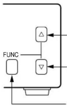
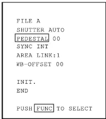
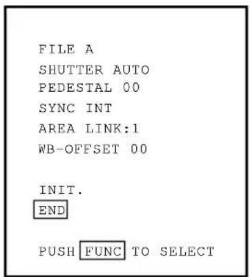
Press the FUNC button to display the menu. The menu appears as shown on the right. Current setting is displayed. Move the cursor to a desired item by moving the cursor up or down using the UP and DOWN buttons, and set an item by pressing the FUNC button. To quit the menu, move the cursor to END and press the FUNC button.
flowchart
graph TD
    A["FUNC"] --> B["△"]
    A --> C["▽"]
    B --> D["Central Function Block"]
    C --> D
    D --> E["Output"]
UP button: The cursor position or data value goes up.
DOWN button: The cursor position or data value goes down.
FUNC button: Selects the item or data value.
Main Menu
FILE A
SHUTTER AUTO
PEDESTAL 00
SYNC INT
AREA LINK:1
WB-OFFSET 00
INIT.
END
PUSH FUNC TO SELECT
Notes:
- When setting is changed in the menu screen, be sure to move the cursor to "END" and press the FUNC button to clear the menu. New setting is stored in the camera.
- Don't turn off the POWER switch before clearing the menu. New setting is not stored, and old data remains.
FILE (Screen File)
There are two scene files A and B which can be selected according to the shooting state.
① Move the cursor to "FILE" in the main menu using the UP or DOWN button.
② Press the FUNC button to display the contents to set FILE, A or B. Move the cursor to A or B using the UP or DOWN button. Press the FUNC button to set the contents.
Note:
- The scene file is for the menu screen. The AGC switch and the WB switch are valid in their set positions.

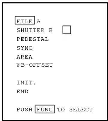
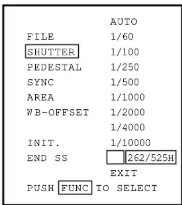
SHUTTER (Electronic Shutter, Backlight Control)
The electronic shutter is available in AUTO (auto electronic shutter), 1/60 \~ 1/10000 and SS (synchronized scan).
AUTO: Controls electronic shutter automatically to get the set video level. Can be selected in backlight correction, peak measurement, average measurement and measurement area.
1/60\~1/10000: Exposure time can be fixed to any one of 1/60, 1/100, 1/250. 1/500, 1/1000, 1/2000, 1/4000 and 1/10000.
SS: Sets the electronic shutter in horizontal scanning time (1H).
① Move the cursor to "SHUTTER" in the main menu using the UP or DOWN button.
② Press the FUNC button to display AUTO \~ EXIT to set SHUTTER. Move the cursor to a desired item of AUTO \~ SS using the UP or DOWN button. Press the FUNC button to frame a desired item in white.
③ Move the cursor to "EXIT" using the UP or DOWN button. Press the FUNC button. Return to the main menu.

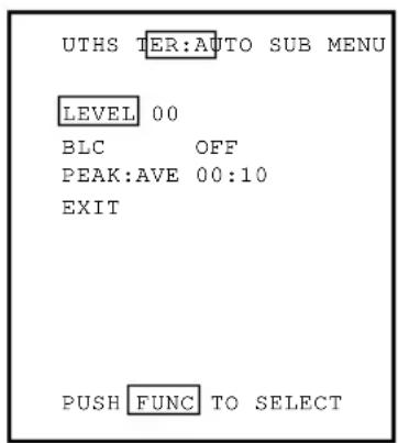
(1) Detail setting in AUTO mode (Auto Electronic Shutter)
When the FUNC button is pressed after AUTO is selected, the submenu for SHUTTER:AUTO appears. Set details in this screen.
LEVEL: Adjust the auto electronic shutter video level. Larger values indicate brighter level, and vice versa. Data can be set in a range of -30 to +30.
BLC: Correction for backlight. This can be set when the measurement area is set to one of "1/2", "1/8" and "SLIT" for AREA in the main menu. Backlight is corrected at ON, but not at OFF. When the measurement area is "1", BLC is displayed in black letters and setting is impossible.
PEAK:AVE: Selects peak or average for measurement of auto electronic shutter video level. The peak to average ratio can be changed in a range of 00:10 to 10:00.
Note:
- While BLC is ON, PEAK:AVE is displayed in black letters and setting is impossible.
① Move the cursor to a desired item (LEVEL, BLC, PEAK:AVE) using the UP or DOWN button. Press the FUNC button. The cursor moves to the data of the selected item. Set the data by pressing the UP or DOWN button.
② After setting the data, press the FUNC button. The cursor moves to the item. To finish setting of submenu, move the cursor to "EXIT" and press the FUNC button to return to "SHUTTER" in the main menu.
(2) SS (Synchronized Scan)
① Move the cursor to "SS" using the UP or DOWN button. Press the FUNC button. (SS is set.)
② Press the FUNC button. The cursor moves to the data and blinks. The data varies in 1/525H to 262/525H when the UP or DOWN button is pressed. Set a desired data, and press the FUNC button.
③ Return to "SS" of SHUTTER.

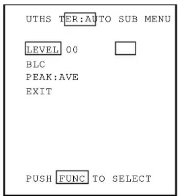
Example of display for LEVEL
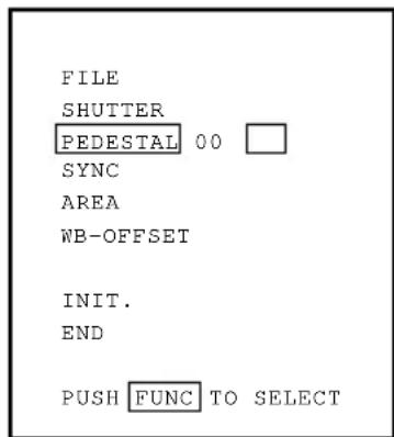
PEDESTAL (Pedestal Level)
① Move the cursor to PEDESTAL using the UP or DOWN button.
② Press the FUNC button. The cursor moves to the data. Set the data using the UP or DOWN button. The data can be set in a range of -50 to +50. After setting the data, press the FUNC button to return to the main menu.
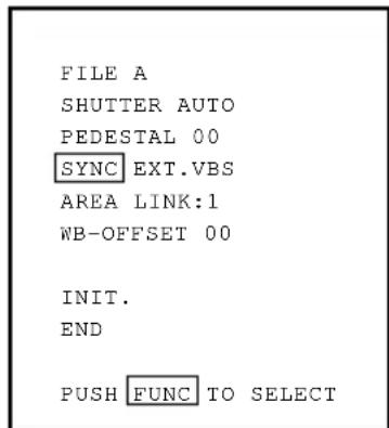
SYNC (Setting for External Sync)
This adjusts horizontal phase and subcarrier phase while externally synchronized. INT is displayed for internal synchronization and changed automatically to EXT when the external synchronizing signal is entered.
① Move the cursor to "SYNC" using the UP or DOWN button.
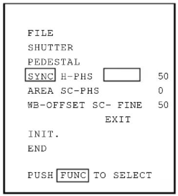
② Press the FUNC button to display the available items (H-PHS, SC-PHS, SC-FINE).
H-PHS: H (horizontal) phase matching 0 \~ 99
SC-PHS: SC (subcarrier) rough adjustment 0, 90, 180, 270
SC-FINE: SC (subcarrier) fine adjustment 0 \~ 99

③ Move the cursor to a desired item (H-PHS, SC-PHS, SC-FINE) using the UP or DOWN button. Press the FUNC button and the data is displayed. Set the data using the UP or DOWN button and press the FUNC button to select the data. To return to the main menu, move the cursor to EXIT and press the FUNC button.
Note:
- If the internal synchronization is set while the SYNC item (H-PHS, SC-PHS, SC-FINE) is being displayed, the display automatically turns to INT disabling setting.
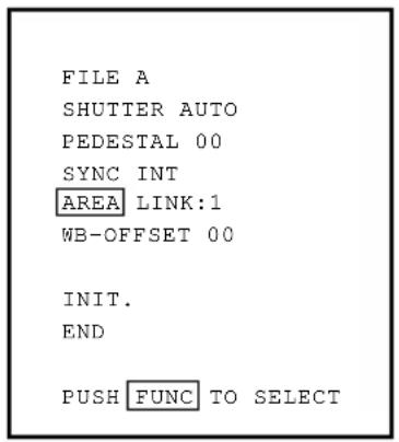
AREA (Measurement Area)
AREA is a measurement AREA item for AGC, auto electronic shutter and white balance. The AREA setting for AGC and auto electronic shutter are the same, so each setting can not be made separately. However, the AREA setting for white balance can be made separately independing on the AREA setting for AGC and auto electronic shutter.
① Move the cursor to AREA using the UP or DOWN button.
② Press the FUNC button to display the available items (LINK, SEP).
③ Move the cursor to a desired item (LINK, SEP) using the UP or DOWN button.
(1) Setting AREA the same for AGC, auto electronic shutter and
white balance
① Move the cursor to LINK using the UP or DOWN button.

② Press the FUNC button to display data 1 \~ SLIT for LINK. Move the cursor to a desired item of AREA data (1, 1/2, 1/8, SLIT) using the UP or DOWN button.
③ Press the FUNC button to set the data.
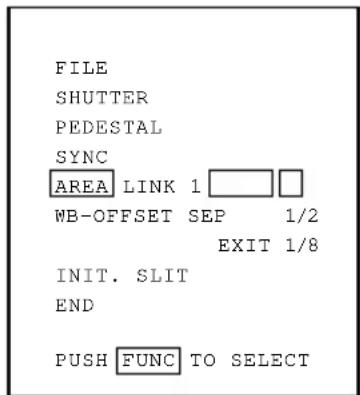
(2) Setting AREA for white balance separately from the AREA
setting for AGC and auto electronic shutter
① Move the cursor to SEP using the UP or DOWN button, and press the FUNC button. SEP is selected and framed in white.
② Press the FUNC button to display the submenu.
③ Move the cursor to a desired item using UP or DOWN button.
WB: Measurement AREA for white balance
1, 1/2, 1/8, SLIT
Valid when the WB switch is AUTO and/or SET.
SHUTTER: Measurement AREA for auto electronic shutter and AGC 1, 1/2, 1/8, SLIT
④ Press the FUNC button to select a desired item. The setting data (1, 1/2, 1/8, SLIT) is displayed. Move the cursor to a desired item using UP or DOWN button, then press the FUNC button to select the data.
⑤ The submenu for AREA appears. Move the cursor to EXIT, and press the FUNC button to return to the main menu.
The size of AREA is approximately as shown below.
(1) 1 (Whole monitor screen) (2) 1/2


bar
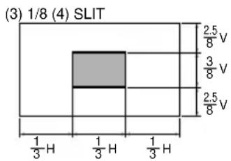
(3) 1/8 (4) SLIT | Category | Value | |---|---| | Top Section | 2.5 V | | Middle Section | 3 V | | Bottom Section | 2.5 V | | Bottom Section (Left) | 1/3 H | | Bottom Section (Right) | 1/3 H | | Bottom Section (Bottom) | 1/3 H |
bar
| Category | Value | |---|---| | 1/8V | 2.5/6H | | 6/8V | 1/6H | | 1/8V | 2.5/6H |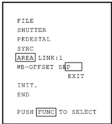


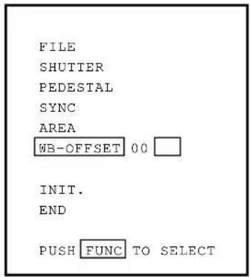
W B-OFFSET (White Balance Offset)
This offsets the focusing point of white balance in the direction of orange or cyan when the WB switch is set to "SET".
① Move the cursor to WB-OFFSET using the UP or DOWN button.
② Press the FUNC button. The cursor moves to the data item.
③ Change the data using the UP or DOWN button.
+20 \~ -20
+ Orange direction
- Cyan direction
Press the FUNC button at a desired data value to set the data.

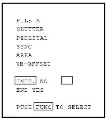
INIT. (Scene File Initialization)
This reset settings of the scene file to the factory setting.
① Select a scene file (A or B) to initialize the setting in FILE.
② Move the cursor to INIT. using the UP or DOWN button.
③ Press the FUNC button. The selected scene file (A or B) is displayed. NO/YES is displayed.
④ Select NO when not initializing. Select YES and press the FUNC button when initializing.

Factory setting (the following setting if INIT. is executed) The setting is common to scene files A and B.
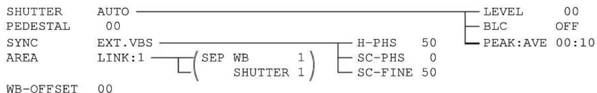
flowchart
graph TD
    A["SHUTTER AUTO"] --> B["LEVEL 00"]
    C["PEDESTAL 00"] --> D["BLC OFF"]
    E["SYNC EXT.VBS"] --> F["H-PHS 50"]
    G["AREA LINK:1"] --> H["SEP WB 1"]
    I["WB-OFFSET 00"] --> J["SHUTTER 1"]
    K["PEAK:AVE 00:10"] --> L["SC-PHS 0"]
    M["SC-FINE 50"] --> N["SC-PHS 0"]
END (End of Screen Display)
To finish the menu, move the cursor to END using the UP or DOWN button and press the FUNC button. To store the setting in the camera, be sure to clear the display by END item. When the display is cleared, the setting is stored in the camera. If the POWER switch is turned off while the menu is being displayed, the setting is not stored and the old data remains.
EXTERNAL SYNC
When using the camera with an external sync, connect a composite video signal (C-VIDEO) to the EXT SYNC terminal on back of the camera control unit. When the camera accepts external sync, it is automatically switched from the internal sync to the external sync.
(1) External sync signal input conditions
C-VIDEO : SYNC section 0.3 ± 0.1V
(75Ω unbalanced)
BURST section
0.3 ± 0.1V
(2) External sync frequency range
Within ±50 ppm referred to NTSC standard frequency
(H frequency 15733.5 Hz to 15735.0 Hz)
(3) Using the camera with external sync signal
When using more than two cameras in external synchronization, this adjustment allows matching of picture tone between two cameras. Adjust H (horizontal) phase and SC (sub carrier) phase if necessary.
(3.1) H (horizontal) phase adjustment
Observe the external sync signal and video output signal on the camera with a dual trace oscilloscope, and adjust "H-PHS" of "SYNC" on the screen menu so that the H phase matches.
Match the phase.
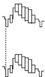
External sync. signal
Camera video output
(3.2) SC (sub carrier) phase adjustment
Perform a coarse adjustment for 0, 90, 180, or
270 degrees in "SC-PHS" on the screen menu and then perform a fine adjustment with "SC-FINE". Using a vector scope for the phase adjustment will provide more accuracy.
CAUTIONS ON USE AND INSTALLATION
- Carefully handle the units.
Do not drop, or give a strong shock or vibration to the camera. This may cause problems. Treat the camera cables carefully to prevent cable problems, such as cable breakdown and loosened connections.
- Do not shoot intense light.
If there is an intense light at a location on the screen such as a spot light, a blooming and smearing may occur. When intense light enters, vertical stripes may appear on the screen. This is not a malfunction. Ghosts may occur when there is an intense light near the object. In this case, change the shooting angle.
• Install the camera in a location free from noise.
If the camera or the cables are located near power utility lines or a TV, etc. undesirable noise may appear on the screen. In such a case, try to change the location of the camera or the cable wiring.
- Moire
When thin stripe patterns are shot, stripe patterns that are not actually there (moire) may appear as interference stripes. This is not a malfunction.
- Operating ambient temperature and humidity.
Do not use the camera in places where temperature and humidity exceed the specifications. Picture quality will lower and internal parts may be damaged.
Be particularly careful when using in places exposed to direct sunlight. When shooting in hot places, depending on the conditions of the object and the camera (for example when the gain is increased), noise in the form of vertical strips or white dots may occur. This is not a malfunction.
- Handling of the protection cap.
Keep the protection cap away from children. Children may put them into mouth or swallow them accidentally. The protection cap protects the image sensing plane when the lens is removed from the camera, do not throw away.
- When not using the camera for a long-time.
Stop supplying power.
- When cleaning the camera
Always turn off the power and clean with a piece of soft dry cloth. Do not use benzine, alcohol, thinner, household detergents, chemically treated cloths, etc. If used, coating and printed letters may be discolored. When cleaning the lens, use a lens cleaning paper, etc.
- Avoid using or storing the camera in the following places:
Places filled with highly flammable gas.
Places near gasoline, benzene, or paint thinner.
Places subject to strong vibration.
Places contacting chemicals (such as pesticides), rubber or vinyl products for a long period of time.
TROUBLESHOOTING CHART
| Symptom | Items to be checked |
| No picture | • Is the power supplied correctly?• Is the lens iris adjusted correctly?• Are the cables connected correctly? |
| Poor color | • Is the monitor (TV) adjusted correctly?• Is the white balance of the camera adjusted correctly? (in modes other than automatic trace)• Is the illumination dark?• Is the SC phase adjusted correctly? (External sync) |
| “HEAD UNCONNECTED” or “CABLE DETECT ERR” is displayed on the screen | • Turn the power of the camera off, make proper connection for the camera head, camera cable, and camera control unit, and then turn the power on again. (Im-proper connection may cause the trouble.) |
OPTIONAL PARTS
Camera head
| Type | Code # | |
| MN43H | 9742-9 | 17mm Micro camera head |
| QN42H | 9657 | 7 mm Super-micro camera head |
| QN42HL | 9657-9 | 7 mm Super-micro camera head |
| CN43H | 9743-9 | C-mount camera head |
| UN43H | 9744-9 | 12 mm Micro camera head |
Camera cable (for MN43H, CN43H, UN43H, MN42H and CN42H)
| Type | Code # | Nominal length | Diameter |
| EMC-02H | 9833 | 2 m | 5.0 mm |
| EMC-03H | 9833-1 | 3 m | 5.0 mm |
| EMC-05H | 9833-2 | 5 m | 5.0 mm |
| EMC-12H | 9833-3 | 12 m | 5.0 mm |
| EMC-20H | 9833-4 | 20 m | 5.0 mm |
| EMC-30H | 9833-5 | 30 m | 5.0 mm |
| EMC-54H | 9833-6 | 54 m | 5.0 mm |
* QN42H camera head is equipped with 3.5 m camera cable.
* QN42HL camera head is equipped with 15 m camera cable.
* EMC-54H cable can be used with MN43H/MN42H/CN43H/CN42H cameras (except UN43H)
Lenses
A wide variety of optional micro and super-micro lenses are available for MN43H and QN43H camera heads. Consult with Elmo dealers for details.
SPECIFICATIONS
Specification with micro camera head (MN43H) connected.
| Power supply DC12V ± 0.5V | ||
| Power consumption 310 mA | ||
| Image sensor 1/2 inch IT-CCD | ||
| Effective pixels Horizontal: 768 pixels, Vertical: 494 pixels | ||
| Effective image area Horizontal: 6.54 mm, Vertical: 4.89 mm (1/2 inch type) | ||
| Scanning system 2:1 interlace | ||
| Scan frequency Horizontal: 15.734 kHz, Vertical: 59.94 Hz | ||
| Sync system Internal/External (automatic switching) | ||
| Resolution Horizontal: More than 470 lines, Vertical: More than 350 lines | ||
| Standard intensity of illumination for objects | 30 lx (F1.6, 3000K) | |
| Minimum intensity of illumination for objects | 2.5 lx (F1.6, 3000K) | |
| S/N ratio 46 dB or more | ||
| Video output | VBS 1.0 V(p-p), (BNC terminal) NTSC system Y/C separation output (S terminal) | |
| Output impedance 75Ω unbalanced | ||
| External sync | Input VBS 1.0 V(p-p) (BNC terminal) NTSC 75Ω unbalanced | |
| Adjustment function | Subcarrier phase, H phase | |
| White balance Automatic/set/manual | ||
| Gain switch (AGC) SENS UP (+6 dB)/ON/OFF | ||
| Electronic shutter | Automatic, 1/60s, 1/100s, 1/250s, 1/500s, 1/1000s, 1/2000s, 1/4000s, 1/10000s, synchronized scan | |
| Operating temperature/humidity | 14°F to 104°F (-10°C to +40°C)/Less than 90% | |
| Anti-vibration/shock characteristics | 70 m/s2(10 to 200 Hz)/700 m/s2 | |
| Weight | Control unit: 0.86 lbs (390g) | |
| Dimensions(Without protrusion) | Control unit: W: 3.35", H: 1.57", D: 6.14"(W: 85 mm, H: 40 mm, D: 156 mm) | |
Design and specifications are subject to change without notice.
PROFILE
Unit: mm [inch]
∅ : diameter
Camera Control Unit
![85 [3.35] 11 [0.43] CAMERA POWER AGC WB ON OFF UP ON OFF AUTO SET MANU WR SET Δ R B FUNC ▽ 20 [0.79] 40 [1.57]](/content/2026/05/1044559/images/8de0291db23fa3dd955df5b7c93ca3f72998be825c58240e325d45f4484bf8b1.jpg)
![156 [6.14] 7 [0.28]](/content/2026/05/1044559/images/58bc6740af7458dacd484946fd36aaa3231cbc18b08ab2026f3e6f83f6873204.jpg)
![10.5 [0.41] 20 [0.79] 21.5 [0.85] 21.5 [0.85] DC IN 12V/EXT/SYNC S-VIDEO VIDEO REMOTE FUNC LOCK IRIS φ12 [0.47] 28 [1.10] 10 [0.39] 9 [0.35] 26.5 [1.04] 3.9 [0.15] 24.5 [0.96] 24 [0.94] 19 [0.75]](/content/2026/05/1044559/images/de985381b0e3b4a13d0cf61f348bfad688048b40324d87d5f1887c0214ab5812.jpg)
![27 [1.06] 114 [4.49] 63 [2.48] 3.9 [0.15] 10.8 [0.43] 4-M3 pitch 0.5 Threaded hole](/content/2026/05/1044559/images/54f0d1cd9c315722159558b9f7f973f8f570ac52a7ad3abde6d115c4eee34a09.jpg)
Servicing Instructions for Service Personnel
Connection to Camera Head (MN42H/ CN42H)
When connecting to the camera head (MN42H/CN42H), select the internal switch inside the camera controller following to the procedures below.
① After turning off the power, remove all the cables connected to the camera controller.
② Remove three screws on the bottom chassis of the camera control unit to remove the internal unit.
③ Turn off No. 3 of S101 switch located on the component side of the internal circuit unit PC board.
| No3 of S101 switch | Applicable camera head to connect |
| OFF | MN42HCN42H |
| ON | MN43HCN43HUN43HQN42HQN42HL |
Note: Do not change the switch settings other than S101. If you change the settings, the normal image may not be obtained.
④ Perform the reverse procedures to assemble.


ELMO CO., LTD.
6-14, Meizen-cho, Mizuho-ku, Nagoya, 467-8567 Japan
OVERSEAS SUBSIDIARY COMPANIES
ELMO Mfg. Corp.
1478 Old Country Road,
Plainview, NY 11803-5034
U.S.A.
Tel. 516-501-1400
Fax. 516-501-0429
E-mail:elmo@elmousa.com
Web:http://www.elmousa.com
ELMO Canada Mfg. Corp.
44 West Drive, Brampton,
Ontario, L6T 3T6,
Canada
Tel. 905-453-7880
Fax. 905-453-2391
E-mail:info@elmocanada.com
Web:http://www.elmocanada.com
ELMO (Europe) G.m.b.H.
Neanderstr. 18
40233 Düsseldorf,
Germany
Tel. 0211-376051-53
Fax. 0211-376630
E-mail:elmoeurope@AOL.com
Web:http://www.elmo.de
ELMO and are registered trademarks of ELMO COMPANY, LIMITED.


- COMPONENTS
- INFORMATION
- Warning
- Caution
- Disclaimer
- Copyright and Right of Portrait
- PART NAMES AND FUNCTIONS
- Camera Control Unit (CCU)
- CONNECTION
- Example of Standard Connection
- Cautions on Connection
- Connection on CCU Back Panel
- Connector Pin Assignments
- • Using the auto-iris lens
- EE lens connector HR10A-7P-4P
- Notes:
- USING CAMERA CONTROL IN FIXED POSITION
- HOW TO USE THE CAMERA
- AGC (Automatic Gain Control)
- White Balance
- White balance adjustment in modes other than AUTO
- (1.1) White balance adjustment in SET mode
- Note:
- (1.2) White balance adjustment in MANU mode
- FUNC (Function Lock)
- Main Menu
- FILE (Screen File)
- SHUTTER (Electronic Shutter, Backlight Control)
- Detail setting in AUTO mode (Auto Electronic Shutter)
- SS (Synchronized Scan)
- PEDESTAL (Pedestal Level)
- SYNC (Setting for External Sync)
- AREA (Measurement Area)
- Setting AREA the same for AGC, auto electronic shutter and
- Setting AREA for white balance separately from the AREA
- setting for AGC and auto electronic shutter
- W B-OFFSET (White Balance Offset)
- INIT. (Scene File Initialization)
- END (End of Screen Display)
- EXTERNAL SYNC
- External sync signal input conditions
- External sync frequency range
- Using the camera with external sync signal
- (3.1) H (horizontal) phase adjustment
- (3.2) SC (sub carrier) phase adjustment
- CAUTIONS ON USE AND INSTALLATION
- - Carefully handle the units.
- - Do not shoot intense light.
- • Install the camera in a location free from noise.
- - Moire
- - Operating ambient temperature and humidity.
- - Handling of the protection cap.
- - When not using the camera for a long-time.
- - When cleaning the camera
- - Avoid using or storing the camera in the following places:
- TROUBLESHOOTING CHART
- OPTIONAL PARTS
- Lenses
- SPECIFICATIONS
- PROFILE
- Camera Control Unit
- Servicing Instructions for Service Personnel
- Connection to Camera Head (MN42H/ CN42H)
- ELMO CO., LTD.
- OVERSEAS SUBSIDIARY COMPANIES
- ELMO Mfg. Corp.
- ELMO Canada Mfg. Corp.
- ELMO (Europe) G.m.b.H.
Brand : Elmo
Model : CC431E
Category : Camera