
EWS1200-52T - Network switch ENGENIUS - Free user manual and instructions
Find the device manual for free EWS1200-52T ENGENIUS in PDF.


| Product Type | Managed Gigabit PoE+ Switch |
| Number of Ports | 48 GE PoE+ + 4 10G SFP+ |
| PoE Budget | 740W |
| Switching Capacity | 176 Gbps |
| Forwarding Rate | 130.95 Mpps |
| Dimensions (W x D x H) | 44.0 x 32.0 x 4.4 cm |
| Weight | 5.0 kg |
| Power Supply | 100-240V AC, 50-60Hz, internal |
| Management | Web GUI, CLI (SSH/Telnet), SNMP v1/v2/v3 |
| Layer Support | Layer 2+ (static routing, VLAN routing) |
| VLAN Features | IEEE 802.1Q, up to 4K VLANs, Q-in-Q |
| QoS | 8 priority queues, IEEE 802.1p, DSCP |
| Security | 802.1X, ACL, MAC filtering, SSH/SSL |
| Spanning Tree | STP, RSTP, MSTP |
| Redundancy | Link Aggregation (LACP), uplink redundancy |
| Cooling | 3 built-in fans, variable speed |
| Mounting | Rack-mountable (2U), included brackets |
| Operating Temperature | 0°C to 50°C |
| Certifications | FCC, CE, RoHS |
Frequently Asked Questions - EWS1200-52T ENGENIUS
User questions about EWS1200-52T ENGENIUS
0 question about this device. Answer the ones you know or ask your own.
Ask a new question about this device
Download the instructions for your Network switch in PDF format for free! Find your manual EWS1200-52T - ENGENIUS and take your electronic device back in hand. On this page are published all the documents necessary for the use of your device. EWS1200-52T by ENGENIUS.
USER MANUAL EWS1200-52T ENGENIUS
EAP1300/EAP1300EXT
version 1.0
Chapter 1 .... 5
Key Features 6
Introduction....7
System Requirements....8
Package Contents 8
Applications 9
Technical Specifications 10
Physical Interface....12
Chapter 2....13
Considerations for Wireless Installation 14
Computer Settings....15
Hardware Installation....19
Mounting the Access Point 20
- Insert the provided short screws into the bottom cover of the AP.... 20
Attaching the AP to a ceiling using the provided T-Rail connector....21
Chapter 3....22
Default Settings....23
Web Configuration....24
Chapter 4....26
Device Status....28
Connections....31
Realtime 31
Chapter 5....34
IPv4 Settings 35
IPv6 Settings 36
Spanning Tree Settings.... 37
Chapter 6....38
Wireless Settings....39
2.4 GHz/5 GHz Wireless Network.... 41
Wireless Security 45
Wireless MAC Filter 48
Traffic Shaping....49
Guest Network 52
RSSI Threshold 54
Management VLAN Settings....55
Chapter 7....56
Controller Settings 57
SNMP Settings 57
CLI/SSH Settings....60
HTTPS Settings....61
Email Alert 62
Date and Time Settings 63
WiFi Scheduler....64
Tools....66
LED Control....69
Device Discovery....70
Chapter 8....71
Account Setting....72
Firmware Upgrade 73
Backup/Restore 74
System Log 75
Reset....77
Logout 78
Appendix 79
Appendix A - FCC Interference Statement 80
Appendix b - CE Interference Statement 81
Chapter 1
Product Overview
Introduction
Key Features
- Deploy and manage with ease using EWS Series Wireless Management Switches.
- Up to 20 dBm transmit power enabling long range connectivity
- Supports IEEE802.11ac/a/b/g/n wireless standards with up to 400 Mbps data rate on 2.4GHz band and 867Mbps on 5GHz band
- Two 5 dBi 2.4 GHz Omni-directional antennas
- Two 5 dBi 5 GHz Omni-directional antennas
• Support Wave 2 MU-MIMO function on 5GHz radio. - Support Tx Beamforming to enlarge the transmitting distance.
• Perform 256-QAM under 2.4GHz for enhancing data rate to 400Mbps - More customized items on Band Steering for intelligent Management.
• Secured Guest Network option available
Introduction
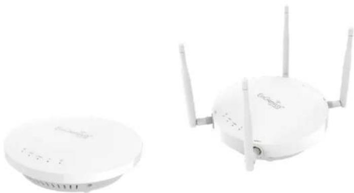
The AP is a great performance, evenly coverage and long-range Dual-Band Wireless 802.11 ac/a/b/g/n indoor Access Point with speeds up to 400 Mbps on 2.4GHz and 867Mbps on 5GHz band. It can be configured as an: Access Point, WDS (AP, Bridge). The AP is designed to operate in a variety of indoor environments. Its high-powered, long-range characteristics make it a cost-effective alternative to ordinary Access Points that don't have the range and reach to connect to a growing number of wireless users who wish to connect to a business network. The AP supports the 2.4GHz frequency band under 802.11 b/g/n mode while at the same time providing 5GHz band under 802.11 ac/a/n mode for communicating to and from 5GHz capable computers, tablets or smart phones or transferring files. Several APs can be deployed in a campus setting using the 5GHz band as a backhaul to provide multiple 2.4GHz wireless cells for computers or mobile devices in common indoor areas.
The AP is easy to install in virtually any location with optional PoE (Power over Ethernet) injector for quick indoor installation. The AP enables network administrators to control its transmit power and feature settings for selecting narrow bandwidth and traffic shaping. The AP also supports wireless encryption including Wi-Fi Protected Access (WPA-PSK/WPA2-PSK) Encryption, and IEEE 802.1x with RADIUS.
Maximum data rates are based on IEEE 802.11 standards. Actual throughput and range may vary depending on many factors including environmental conditions, distance between devices, radio interference in the operating environment, and mix of devices in the network. Features and specifications are subjected to change without prior notice. Trademarks and registered trademarks are the property of their respective owners. For United States of America: Copyright © 2017 EnGenius Technologies, Inc. All rights reserved.
System Requirements
The following are the Minimum System Requirements in order to configure the device:
- Computer with an Ethernet interface or wireless network capability
- Windows OS (XP, Vista, 7, 8), or Mac OS, Linux-based operating systems
- Web-Browsing Application (i.e. Edge, Internet Explorer, Firefox, Safari, or another similar browser application)
Package Contents
The package contains the following items (all items must be in package to issue a refund):
- EAP Access Point
- Mounting Bracket
- Bracket Screw
- Quick Installation Guide
- 2 detachable 4 dBi 2.4 GHz Omni-directional Antennas (EAP1300EXT only)
- 2 detachable 5 dBi 5 GHz Omni-directional Antennas(EAP1300EXT only)
Applications
Wireless LAN (WLAN) products are easy to install and highly efficient. The following list describes some of the many applications made possible through the power and flexibility of WLANs:
- Difficult-to-Wire Environments: There are many situations where wires cannot be installed, deployed easily, or cannot be hidden from view. Older buildings, sites with multiple buildings, and/or areas that make the installation of a Ethernet-based LAN impossible, impractical or expensive are sites where WLAN can be a network solution.
- Temporary Workgroups: Create temporary workgroups/networks in more open areas within a building; auditoriums, amphitheaters classrooms, ballrooms, arenas, exhibition centers, or temporary offices where one wants either a permanent or temporary Wireless LAN established.
- The Ability to Access Real-Time Information: Doctors/Nurses, Point-of-Sale Employees, and/or Warehouse Workers can access real-time information while dealing with patients, serving customers, and/or processing information.
- Frequently Changing Environments: Set up networks in environments that change frequently (i.e.: Show Rooms, Exhibits, etc.).
- Small Office and Home Office (SOHO) Networks: SOHO users require a cost-effective, easy, and quick installation of a small network.
- Training/Educational Facilities: Training sites at corporations or students at universities use wireless connectivity to exchange information between peers and easily access information for learning purposes.
Technical Specifications
EAP1300/EAP1300EXT
Radio Specification
Dual Concurrent Radio:
- 2.4GHz: 802.11b/g/n with max data rate up to 400Mbps
- 5GHz: 802.11ac/n with max data rate up to 867Mbps
Transmit Power:
- Max transmit power is limited by regulatory power
Radio Chains / Spatial Streams:
-2×2/2
Supported Radio Technology:
- 802.11b: direct-sequence spread-spectrum (DSSS)
- 802.11a/g/n: orthogonal frequency-division multiplexing (OFDM)
Channelization:
- 802.11n with 20/40 MHz channel width
- 802.11a/b/g with 20 MHz channel width
Supported Modulation:
-802.11b: BPSK, QPSK, CCK
-802.11a/g/n: BPSK, QPSK, 16-QAM, 64-QAM
Supported data rates (Mbps):
-802.11b: 1, 2, 5.5, 11
-802.11a/g:6,9,12,18,24,36,48,54
-802.11n: 6.5 to 300 (MCS0 to MCS23)
Physical & Environment
Power Source:
- DC Input: DC12V/1A
- PoE: compatible with 802.3af
Internal Antenna (EAP1300):
- 5 dBi 2.4GHz antennas
- 5 dBi 5GHz antennas
External Antenna (EAP1300EXT):
- 2x 4dBi 2.4GHz antennas
- 2x 5dBi 5GHz antennas
Interface:
- 1 x 10/100/1000Mbps Uplink Port with 802.3af/at PoE
- 1 x DC power connector
- 1 x Reset button
Dimensions:
Diameter: 6.36" (161.54 mm)
Mounting:
- Wall mount (standard US/EU single gang wall jack)
Environment:
- Operating temperature: 0°C\~40°C
- Operating humidity: 0%\~90% typical
- Storage temperature: -20°C\~60°C
Wireless
Operating Mode:
-AP Mode
Auto Channel Selection:
- Setting varies by regulatory domains
SSIDs:
- Supports up to 8 SSIDs per frequency band
VLAN Tag / VLAN Pass-through
Wireless Client List
Guest Network:
- Allocates a separate network segment for guest access within the same WLAN
QoS:
- Supports 802.11e/WMM
Band Steering
Mobility:
- PMKSA support for fast roaming
Security:
- WEP encryption: 64/128/152-bit
- WPA/WPA2 Enterprise/PSK
- Hidden SSID
- MAC address filtering (up to 50 MAC)
- Client isolation
Management
Deployment Options
- Standalone Mode
- Managed Mode (by Neutron Switch)
Configuration
- Web interface (HTTP)
- SNMP v1/v2c/v3 with MIB I/II and private MIB
- CLI (Telnet)
Firmware Upgrade
- Web interface or CLI (FTP/HTTP)
- Revert to factory default settings
Schedule Reboot:
- Specifies interval to reboot system periodically
E-mail Alert / Syslog Notification
Physical Interface

- LED Indicators: LEDs for Power, WAN, 2.4Hz, 5GHz, LAN, Reserved
- Reset Button: Press and hold for over 10 seconds to reset to factory default settings.
- RSMA Connector for external antenna(EAP1300EXT)
- DC12V Input: DC12V/1A power in
- 10/100/1000 RJ45 Uplink (PoE In): Uplink port that supports 802.3af/at PoE input
Chapter 2
Before You Begin
Before You Begin
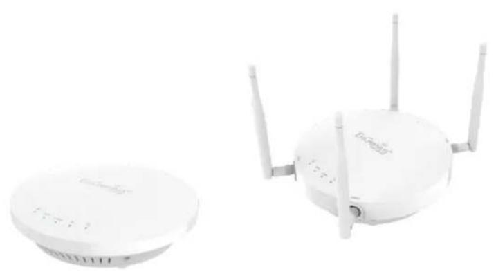
This section will guide you through the installation process. Placement of the EnGenius Access Point is essential to maximize the Access Point's performance. Avoid placing the Access Point in an enclosed space such as a closet, cabinet, or stairwell.
Considerations for Wireless Installation
The operating distance of all wireless devices can often not be pre-determined due to a number of unknown obstacles in the environment in which the device is deployed. Obstacles such as the number, thickness, and location of walls, ceilings, or other objects that the Access Point's wireless signals must pass through can weaken the signal. Here are some key guidelines for allowing the Access Point to have an optimal wireless range during setup.
- Keep the number of walls and/or ceilings between the Access Point and other network devices to a minimum. Each wall and/or ceiling can reduce the signal strength, resulting in a lower overall signal strength.
- Building materials make a difference. A solid metal door and/or aluminum stubs may have a significant negative effect on the signal strength of the Access Point. Locate your wireless devices carefully so the signal can pass through drywall and/or open doorways. Materials such as glass, steel, metal, concrete, water (example: fish tanks), mirrors, file cabinets, and/or brick can also diminish wireless signal strength.
- Interference from your other electrical devices and/or appliances that generate RF noise can also diminish the Access Point's signal strength. The most common types of devices are microwaves or cordless phones.
Computer Settings
Windows XP/Windows 7
In order to use the Access Point, you must first configure the TCP/IPv4 connection of your Windows OS computer system.
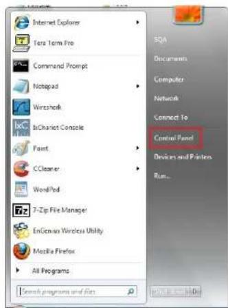
1. Click the Start button and open the Control Panel

Windows XP
Windows 7
2a. In Windows XP, click on Network Connections.

2b. In Windows 7, clickView network status and tasksin the Network and Internetsection, then selectChange adapter settings.

Network and Internet
View network status and tasks
Choose homegroup and sharing options
Control Panel Home
Change adapter settings
Change advanced sharing settings
-
Right click obocal Area Connection and select Properties
-
Select Internet Protocol Version 4 (TCP/IPv4) then select Properties


- SelectUse the following IP addressed enter an IP address that is different from the Access Point and Subnet mask, then click OK.
Note: Ensure that the IP address and Subnet mask are on the same subnet as the device.
For example: Access Point IP address: 192.168.1.1
PC IP address: 192.168.1.2 - 192.168.1.255
PC Subnet mask: 255.255.255.0

Apple Mac OS X
- Go to System Preferences(it can be opened in the Applications folder or by selecting it in the Apple Menu).
- Select Network in the Internet & Network section.

- HighlightEthernet.
- In Configure IPv4 select Manually.
- Enter an IP address that is different from the Access Point and Subnet mask, then clickOK.
Note: Ensure that the IP address and Subnet mask are on the same subnet as the device.
For example: Access Point IP address: 192.168.1.1
PC IP address: 192.168.1.2 - 192.168.1.255
PC Subnet mask: 255.255.255.0
- Click Apply when finished.

Hardware Installation
- Connect one end of a RJ45 Ethernet cable to the Ethernet port on the rear of the Access Point.
- Connect the other end of the RJ45 Ethernet cable to a PoE Ethernet switch or the PoE Out port on the PoE injector.
- Using another RJ45 Ethernet cable, connect one end to the Ethernet port on the computer, and connect the other end to another port on the PoE Ethernet switch or to the Data In port on the PoE injector.
- Provide power to the PoE injector/switch.
- Verify that the Power LED on the AP is steady orange.
- Proceed to set up the Access Point using the computer.

The Access Point supports both IEEE 802.3af/at PoE (Power over Ethernet) or an optional DC power adapter (sold separately). You may use either one as the power source. DO NOT use both at the same time.
Mounting the Access Point
Using the provided hardware, the AP can be attached to a ceiling or wall.
To attach the AP to a ceiling or wall using the mounting bracket:
-
Attach the mounting bracket to the wall or ceiling using the provided wall/ceiling mounting hardware kit.
-
Insert the provided short screws into the bottom cover of the AP.
Leave enough of the screws exposed to ensure that the unit can be attached to the mounting bracket.
If extra space is required, use the provided spacers and long screws from the T-Rail mounting hardware kit to increase the space between the unit and the mounting bracket.
- Mount the AP on the mounting bracket by rotating the unit clockwise about 90 degrees to secure it in place.


Lock the EAP1750H by revolving
Attaching the AP to a ceiling using the provided T-Rail connector
- Attach the T-Rail connectors to the bottom cover of the AP using the provided short screws.
Note: Two sizes of T-Rail connectors are included in the mounting hardware kit: 15/16in (2.38cm) and 9/16in (1.43cm). If extra space is required to accommodate drop ceiling tiles, use the provided spacers and long screws.
- Line up the connected T-Rail connectors with an appropriately sized rail and press the unit onto the rail until it snaps into place.
Note: To protect your AP, use the Kensington Security Slot to attach a cable lock (cable lock is not included).

Chapter 3
Configuring Your Access Point

Configuring Your Access Point
This section will show you how to configure the device using the web-based configuration interface.
Default Settings
Please use your Ethernet port or wireless network adapter to connect the Access Point.
| IP Address | 192.168.1.1 |
| Username/Password | admin/admin |
Web Configuration
- Open a web browser (Internet Explorer/Firefox/Safari/Chrome) and enter the IP Address http://192.168.1.1.
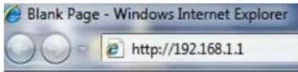
Note: If you have changed the default LAN IP Address of the Access Point, ensure you enter the correct IP Address.
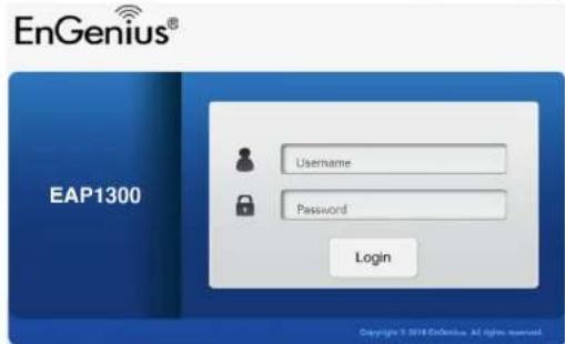
- The default username and password are: admin. Once you have entered the correct username and password, click the Login button to open the web-based configuration page.
- If successful, you will be logged in and see the Access Point User Interface.
*Model name varies depending on model.
EnGenius®
EAP1300
Dual Radio AP, 2T2R, 400Mbps +867Mbps
Changes : 0
Reset
Logout

Overview
Device Status
Connections

Network
Basic
Wireless

Management
Advanced
Time Zone
WiFi Scheduler
Tools

System Manager
Account
Firmware
Log
Device Information
| Device Name | EAP1300 |
| MAC Address | |
| - LAN | 88:DC:96:40:40:4A |
| - Wireless LAN - 2.4GHz | 88:DC:96:40:40:4C |
| - Wireless LAN - 5GHz | 88:DC:96:40:40:4D |
| Country | USA |
| Current Local Time | Fri Jul 24 05:55:27 UTC 2015 |
| Firmware Version | 2.0.56 + 1.5.6 |
| Management VLAN ID | Untagged |
LAN Information - IPv4
| IP Address | 192.168.1.1 |
| Subnet Mask | 255.255.255.0 |
| Gateway | |
| Primary DNS | |
| Secondary DNS |
Chapter 4
Overview

Overview
Save Changes
This page lets you save and apply the settings shown ununsaved changes list or Revert the unsaved changes and revert to the previous settings that were in effect.
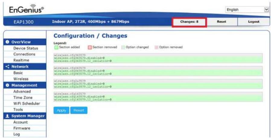
The Overview section contains the following options:
- Device Status
- Connections
The following sections describe these options.
Device Status
Clicking the Device Statuslink under theOverview menu shows the status information about the current operating mode.
- The Device Information section shows general system information such as Device Name, MAC address, Current Time, Firmware Version, and Management VLAN ID.
Note: VLAN ID is only applicable in Access Point, WDS AP or WDS BR mode.
Device Information
| Device Name | EAP1300 |
| MAC Address | |
| - LAN | 88:DC:96:40:40:4A |
| - Wireless LAN - 2.4GHz | 88:DC:96:40:40:4C |
| - Wireless LAN - 5GHz | 88:DC:96:40:40:4D |
| Country | USA |
| Current Local Time | Fri Jul 24 05:55:27 UTC 2015 |
| Firmware Version | 2.0.56 + 1.5.6 |
| Management VLAN ID | Untagged |
• The Memory Information section shows usage of memory such as Total Available, Free, Cached, Buffered.
Memory Information
| Total Available | 148384 kB / 236320 kB (62%) |
| Free | 113640 kB / 236320 kB (48%) |
| Cached | 25460 kB / 236320 kB (10%) |
| Buffered | 9284 kB / 236320 kB (3%) |
- The LAN Information section shows the Local Area Network settings such as the LAN IP Address, Subnet mask, Gateway, DNS Address, DHCP Client, and Spanning Tree Protocol(STP) status.
LAN Information - IPv4
| IP Address | 192.168.1.1 |
| Subnet Mask | 255.255.255.0 |
| Gateway | |
| Primary DNS | |
| Secondary DNS | |
| DHCP Client | Enable |
| Spanning Tree Protocol (STP) | Disable |
LAN Information - IPv6
| IP Address | N/A |
| Link-Local Address | fe80::8adc:96ff.fe54:3216 |
| Gateway | N/A |
| Primary DNS | N/A |
| Secondary DNS | N/A |
- The Wireless LAN Information 2.4 GHz/5GHz section shows wireless information such as Operating Mode, Frequency, and Channel. Since the Access Point supports multiple-SSIDs, information about each SSID and security settings are displayed. Note: Profile Settings are only applicable in Access Point and WDS AP modes.
Wireless LAN Information - 2.4GHz
| Operation Mode | Access Point | ||||
| Wireless Mode | 802.11 B/G/N | ||||
| Channel Bandwidth | 20-40 MHz | ||||
| Channel | 2.412 GHz (Channel 1) | ||||
| Profile | SSID | Security | VID | 802.1Q | |
| #1 | EnGenius543218_1-2.4GHz | None | 1 | Disable | |
| #2 | EnGenius543218_2-2.4GHz | None | 2 | Disable | |
| #3 | EnGenius543218_3-2.4GHz | None | 3 | Disable | |
| #4 | EnGenius543218_4-2.4GHz | None | 4 | Disable | |
| #5 | EnGenius543218_5-2.4GHz | None | 5 | Disable | |
| #6 | EnGenius543218_6-2.4GHz | None | 6 | Disable | |
| #7 | EnGenius543218_7-2.4GHz | None | 7 | Disable | |
| #8 | EnGenius543218_8-2.4GHz | None | 8 | Disable | |
Wireless LAN Information - 5GHz
| Operation Mode | Access Point | ||||
| Wireless Mode | 802.11 A/N | ||||
| Channel Bandwidth | 40 MHz | ||||
| Channel | 5.18 GHz (Channel 36) | ||||
| Profile | SSID | Security | VID | 802.1Q | |
| #1 | EnGenius543219_1-5GHz | None | 51 | Disable | |
| #2 | EnGenius543219_2-5GHz | None | 52 | Disable | |
| #3 | EnGenius543219_3-5GHz | None | 53 | Disable | |
| #4 | EnGenius543219_4-5GHz | None | 54 | Disable | |
| #5 | EnGenius543219_5-5GHz | None | 55 | Disable | |
| #6 | EnGenius543219_6-5GHz | None | 56 | Disable | |
| #7 | EnGenius543219_7-5GHz | None | 57 | Disable | |
| #8 | EnGenius543219_8-5GHz | None | 58 | Disable | |
• The Statistics section shows Mac information such as SSID, MAC address, RX and TX.
Statistics
| SSID | MAC | RX(Packets) | TX(Packets) |
| Ethernet | 88:DC:96:5C:45:DC | 5.00 MB(54832 Pkts.) | 5.12 MB(4264 Pkts.) |
Connections
Clicking the Connections link under the Device Status menu displays the list of clients associated to the Access Point's 2.4GHz/5GHz, along with the MAC address, TX, RX and signal strength for each client. Clicking Kick in the Block column removes this client.
Connection List - 2.4GHz
| SSID | MAC Address | TX | RX | RSSI | Block |
| Connection List - 5GHz | |||||
| SSID | MAC Address | TX | RX | RSSI | Block |
| EnGenius05B06A_1-5GHz | 00:02:6F:93:47:5C | 162Kb | 30Kb | -42dBm | Kick |
Refresh
Click Refresh to refresh the Connection List page.
Note: Only applicable in Access Point and WDS AP modes.
Realtime
Realtime
The Realtime section contains the following options:
CPU Loading: 3 minutes CPU loading percentage information, it displays current loading, average loading and peak loading status. Left bar is loading percentage; button is time tracing. Interval is every 3 seconds

Traffic Loading: 2.4GHz and 5GHz and Ethernet port inbound and outbound traffic by current, average and peak time.

Realtime Connection (Pkts): Overview on current active network connections. It displays UDP and TCP packets information and other connection status. UDP connections curve is in blue; TCP connection curve is in green; others curve is in red. Below of chart shows connections source and destination.
Load Traffic Connections
Realtime Connections (Pkts)

Chapter 5
Network

Basic
This page allows you to modify the device's IP settings and the Spanning Tree settings. Enabling Spanning Tree protocol will prevent network loops in your LAN network.
IPv4 Settings
IPv4 Settings
| IP Network Setting | ○ DHCP ● Static IP |
| IP Address | 192.168.1.1 |
| Subnet Mask | 255.255.255.0 |
| Gateway | 192.168.1.1 |
| Primary DNS | 0.0.0.0 |
| Secondary DNS | 0.0.0.0 |
IP Network Setting Select whether the device IP address will use the static IP address specified in the IP Address field or be obtained automatically when the device connects to a DHCP server.
IP Address The IP Address of this device.
IP Subnet Mask The IP Subnet mask of this device.
Gateway. The Default Gateway of this device. Leave it blank if you are unsure of this setting.
Primary/Secondary DNS The primary/secondary DNS address for this device.
IPv6 Settings
| IPv6 Settings | Link-local Address |
| IP Address | |
| Subnet Prefix Length | |
| Gateway | |
| Primary DNS | |
| Secondary DNS |
Link-Local Address Check this if you want to use Link-Local Address.
IP Address The IPv6 IP Address of this device.
Subnet Prefix Length The IPv6 Subnet Prefix Length of this device.
Gateway: The IPv6 Default Gateway of this device. Leave it blank if you are unsure of this setting.
Primary / Secondary DNS The primary / secondary DNS address for this device.
Spanning Tree Settings
This page allows you to modify the Spanning Tree settings. Enabling the Spanning Tree protocol will prevent network loops in your LAN network.
Spanning Tree Protocol (STP) Settings
| Status | ○ Enable ● Disable | |
| Hello Time | 2 | seconds (1-10) |
| Max Age | 20 | seconds (6-40) |
| Forward Delay | 4 | seconds (4-30) |
| Priority | 32768 | (0-65535) |

Save current setting(s)
Status Enables or disables the Spanning Tree functionDefault is Disable.
Hello Time Specify Bridge Hello Time, in seconds. This value determines how often the device sends handshake packets to communicate information about the topology throughout the entire Bridged Local Area Network.
Max Age Specify Bridge Max Age, in seconds. If another bridge in the spanning tree does not send a hello packet for a long period of time, it is assumed to be inactive.
Forward Delay Specifies Bridge Forward Delay, in seconds. Forwarding Delay Time is the time spent in each of the Listening and Learning states before the Forwarding state is entered. This delay is provided so that when a new bridge comes onto a busy network, it analyzes data traffic before participating in the network.
Priority. Specify the Priority Number. A smaller number has greater priority than a larger number.
Save: Click Save to confirm the changes.
Chapter 6
2.4GHz & 5GHz Wireless

Basic
Wireless Settings
Wireless Settings
| Device Name | EAP1300 | |
| Country / Region | Please select the country | |
| Band Steering | Disabled | |
| NOTE: In order for Band Steering function to work properly, both 2.4GHz and 5GHz SSID and Security Settings must be the same. | ||
Device Name Enter a name for the device. The name you type appears in SNMP management. This name is not the SSID and is not broadcast to other devices.
Band Steering Enable Band Steering to send 802.11n clients to the 5 GHz band, where 802.11b/g clients cannot go, and leave 802.11b/g clients in 2.4GHz to operate at their slower rates. Before implementing this feature, we suggest you to assure the both 2.4GHz and 5GHz SSID, as well as security settings must be the same. EnGenius Band Steering supports following advanced settings,
Wireless Settings
| Device Name | EAP1300 | |
| Country / Region | Please select the country | |
| Band Steering | Force 5GHz | |
| INFORMATION: When band steering is configured to Force 5GHz mode, the AP will not allow a dual band client to connect to the 2.4GHz band only if the client is not currently associated on the 2.4Ghz radio of this AP.NOTE: In order for Band Steering function to work properly, both 2.4GHz and 5GHz SSID and Security Settings must be the same. | ||
*Force 5GHz: When band steering is configured to Force 5GHz mode, the AP will not dual band capable client devices to network to the 2.4GHz band only if the client devices are not currently associated on 2.4GHz radio in this AP.
| Prefer 5GHz | ||
| Band Steering | 5GHz RSSI | -75 dBm |
| NOTE: In order for Band Steering function to work properly, both 2.4GHz and 5GHz SSID and Security Settings must be the same. | ||
*Prefer 5GHz When band steering is configured to Prefer 5GHz mode, the AP will steer dual band capable client devices to 5GHz radio when the RSSI value of these client devices on 5GHz radio is more than set one. The allowed RSSI value for default setting is -75dBm.

*Band Balance When band steering is configured to Band Balance mode, the AP will steer dual band capable client devices to 5GHz when the RSSI value of these client devices on 5GHz radio is more than set one. To evenly allocate RF resource on the both 2.4GHz and 5GHz radios, users also can set the portion of client devices on 5GHz radio to assure smoothly connection. The default value of the 5GHz radio is 75% .
Save: Click Save to confirm the changes.
This page displays the current status of the Wireless settings of this AP.
2.4 GHz/5 GHz Wireless Network
| 2.4GHz | 5GHz | |||||
| Operation Mode | Access Point | ✓ | Green | Access Point | ✓ | Green |
| Wireless Mode | 802.11 B/G/N | ✓ | 802.11 AC/N | ✓ | ||
| Channel HT Mode | 20MHz | ✓ | 40MHz | ✓ | ||
| Channel | Configuration | |||||
| Transmit Power | Auto | Auto | ||||
| Data Rate | Auto | Auto | ||||
| RTS/CTS Threshold (1 - 2346) | 2346 | 2346 | ||||
| Client Limits | 127 | ● Enable ○ Disable | 127 | ● Enable ○ Disable | ||
| Aggregation | ● Enable ○ Disable | |||||
| 64 | Frames | |||||
| 65535 | Bytes(Max) | |||||
| AP Detection | Scan | Scan | ||||
Operation Mode Scrow down this list to select operation modes (Access Point, WDS Access Point and WDS Bridge) for implementing on this radio. The default operation mode is Access Point.
Wireless Mode Scrow down this list to select wireless broadcasting standard on 2.4GHz and 5GHz frequency bands.
Channel HT Mode Scrow down this list to select bandwidth for operating under a frequency band. The default channel bandwidth is 20 MHz on 2.4GHz frequency radio and 40 MHz on 5GHz frequency radio. Considering the different applications, users can decide to implement a channel bandwidth to fulfill real applications. The larger of the channel, the greater of transmission quality and speed.
Transmit Power (Tx Power) Default Tx power is Auto to obey regulatory power of each country.
Channel: Click Configuration button to open a new window to configure channels for performing wireless service.
2.4GHz
| All | None | All | None |
| 1,6,11 | 1,4,8,11 | U-NII-1 | U-NII-2A |
| 1,7,13 | 1,5,9,13 | U-NII-2B | |
| Ch 01 : 2.412 GHz | Ch 02 : 2.417 GHz | Ch 36 : 5.180 GHz | Ch 40 : 5.200 GHz |
| Ch 03 : 2.422 GHz | Ch 04 : 2.427 GHz | Ch 44 : 5.220 GHz | Ch 48 : 5.240 GHz |
| Ch 05 : 2.432 GHz | Ch 06 : 2.437 GHz | Ch 52 : 5.260 GHz | Ch 56 : 5.280 GHz |
| Ch 07 : 2.442 GHz | Ch 08 : 2.447 GHz | Ch 60 : 5.300 GHz | Ch 64 : 5.320 GHz |
| Ch 09 : 2.452 GHz | Ch 10 : 2.457 GHz | Ch100 : 5.500 GHz | Ch104 : 5.520 GHz |
| Ch 11 : 2.462 GHz | Ch 12 : 2.467 GHz | Ch108 : 5.540 GHz | Ch112 : 5.560 GHz |
| Ch 13 : 2.472 GHz | Ch132 : 5.660 GHz | Ch136 : 5.680 GHz |
*Default configuration Default setting of channel selection isAll" to perform auto channel on the exist channel list.
*None: Click "None" to disable the setting on this radio. This radio is disabled.
*Group Configuration Click specific groups of channels for performing auto channel function. For example, users can click U-NII-1 and U-NII-3 to perform auto channel on these bands; the mechanism of this AP will select the relatively optimal channel to perform wireless service.
Data Rate Select a data rate from the drop-down list. The data rate affects throughput of data in the AP. Select the best balance for you and your network but note that the lower the data rate, the lower the throughput, though transmission distance is also lowered.
RTS/CTS Threshold Specifies the threshold package size for RTC/CTS. A small number causes RTS/CTS packets to be sent more often and consumes more bandwidth.
Client Limits Limits the total number of clients on this radio. Once setting the ceiling of client numbers, the maximum associated client devices will be restricted at this number.
Aggregation Integrate multiple data packets into one packet to deliver to client devices. This option reduces the number of packets, but also increases packet sizes.
AP Detection AP Detection can select the best channel to use by scanning nearby areas for Access Points.
Distance Specifies the distance between Access Points and client devices. The proper setting for this parameter may assist Access Points to avoid the improper operation when transmitting data under a filed application.
Save: Click Save to confirm the changes or Cancel to cancel and return to previous settings.
2.4GHz/5GHz SSID Profile
Under Wireless Settings, you can edit the SSID profile to fit your needs. Click Edit under the SSID you would like to make changes to.
Wireless Settings - 2.4GHz
| No. | Enable | SSID | Edit | Security | Hidden SSID | Client Isolation | VLAN Isolation | VLAN ID |
| 1 | ☑ | EnGenius05B069_1-2.4GHz | Edit | None | ☐ | ☐ | 1 | |
| 2 | ☐ | EnGenius05B069_2-2.4GHz | Edit | None | ☐ | ☐ | 2 | |
| 3 | ☐ | EnGenius05B069_3-2.4GHz | Edit | None | ☐ | ☐ | 3 | |
| 4 | ☐ | EnGenius05B069_4-2.4GHz | Edit | None | ☐ | ☐ | 4 | |
| 5 | ☐ | EnGenius05B069_5-2.4GHz | Edit | None | ☐ | ☐ | 5 | |
| 6 | ☐ | EnGenius05B069_6-2.4GHz | Edit | None | ☐ | ☐ | 6 | |
| 7 | ☐ | EnGenius05B069_7-2.4GHz | Edit | None | ☐ | ☐ | 7 | |
| 8 | ☐ | EnGenius05B069_8-2.4GHz | Edit | None | ☐ | ☐ | 8 |
Wireless Settings - 5GHz
| No. | Enable | SSID | Edit | Security | Hidden SSID | Client Isolation | VLAN Isolation | VLAN ID | |
| 1 | ☑ | EnGenius05B06A_1-5GHz | Edit | None | ☐ | ☐ | ☐ | 51 | |
| 2 | ☐ | EnGenius05B06A_2-5GHz | Edit | None | ☐ | ☐ | ☐ | 52 | |
| 3 | ☐ | EnGenius05B06A_3-5GHz | Edit | None | ☐ | ☐ | ☐ | 53 | |
| 4 | ☐ | EnGenius05B06A_4-5GHz | Edit | None | ☐ | ☐ | ☐ | 54 | |
| 5 | ☐ | EnGenius05B06A_5-5GHz | Edit | None | ☐ | ☐ | ☐ | 55 | |
| 6 | ☐ | EnGenius05B06A_6-5GHz | Edit | None | ☐ | ☐ | ☐ | 56 | |
| 7 | ☐ | EnGenius05B06A_7-5GHz | Edit | None | ☐ | ☐ | ☐ | 57 | |
| 8 | ☐ | EnGenius05B06A_8-5GHz | Edit | None | ☐ | ☐ | ☐ | 58 | |
Current Profile You can configure up to sixteen (16) different SSIDs (eight (8) per band). If multiple client devices will be accessing the network, you can arrange the devices into SSID groups. Click Edit to configure the profile and check whether you want to enable extra SSID.
Enable: Click this check box to enable this SSID interface. The default SSIDs are enable on the both first 2.4GHz and 5GHz SSID.
SSID: Specifies the SSID for the current profile.
Security: Displays the Security Mode the SSID uses. You can click Edit to change the security mode. For more details, see the next section.
Hidden SSID: Check this option to hide the SSID from clients. If checked, the SSID will not appear in the site survey.
Client Isolation: Check this option to prevent communication between client devices.
VLAN Isolation: Check this option to enable VLAN Isolation feature.
VLAN ID: Specifies the VLAN tag for each profile. If your network includes VLANs, you can specify a VLAN ID for packets pass through the Access Point with a tag.
L2 Isolation Enable this function prevents client devices to communicate on the both WLAN and LAN.
Save: Click Save to accept the changes
Wireless Security
The Wireless Security section lets you configure the Access Point's security modes: WEP, WPA-PSK, WPA2-PSK, WPA-PSK Mixed, WPA-Enterprise, WPA2-Enterprise and WPA Mixed Enterprise.
It is strongly recommended that you use WPA2-PSK Click on the Edit button under Wireless Settings next to the SSID to change the security settings.
WEP
| Security Mode | WEP |
| Auth Type | Open System |
| Input Type | Hex |
| Key Length | 40/64-bit (10 hex digits or 5 ASCII char) |
| Default Key | 1 |
| Key1 | |
| Key2 | |
| Key3 | |
| Key4 |
Auth Type: Select Open System or Shared Key.
Input Type: ASCII: Regular Text (Recommended) or HEX: Hexadecimal Numbers (For advanced users).
Key Length: Select the desired option and ensure the wireless clients use the same setting. Your choices are: 64, 128, and 152-bit password lengths.
Default Key: Select the key you wish to be default. Transmitted data is ALWAYS encrypted using the Default Key; the other Keys are for decryption only. You must enter a Key Value for the Default Key.
Encryption Key: Enter the Key Value or values you wish to use. The default is none.
WPA-PSK/WPA2-PSK (Pre-Shared Key)
| Security Mode | WPA-PSK Mixed |
| Encryption | Both(TKIP+AES) |
| Passphrase | |
| Group Key Update Interval | 3600 |
Encryption: Select the WPA/WPA2 encryption type you would like to use. Available options are Both, TKIP(Temporal Key Integrity Protocol) and AES(Advanced Encryption Standard). Please ensure that your wireless clients use the same settings.
Passphrase: Wireless clients must use the same Key to associate the device. If using ASCII format, the Key must be from 8 to 63 characters in length. If using HEX format, the Key must be 64 HEX characters in length.
Group Key Update Interval: Specify how often, in seconds, the Group Key changes.
WPA/WPA2-Enterprise
| Security Mode | WPA Mixed-Enterprise |
| Encryption | Both(TKIP+AES) |
| Group Key Update Interval | 3600 |
| Radius Server | |
| Radius Port | 1812 |
| Radius Secret | |
| Radius Accounting | Disable |
| Radius Accounting Server | |
| Radius Accounting Port | 1813 |
| Radius Accounting Secret | |
| Interim Accounting Interval | 600 |
Encryption: Select the WPA/WPA2 encryption type you would like to use. Available options are Both, TKIP(Temporal Key Integrity
Protocol) and AES(Advanced Encryption Standard). Please ensure that your wireless clients use the same settings.
Group Key Update Interval: Specify how often, in seconds, the group key changes.
Radius Server: Enter the IP address of the Radius server.
Radius Port: Enter the port number used for connections to the Radius server.
Radius Secret: Enter the secret required to connect to the Radius server.
Radius Accounting: Enables or disables the accounting feature.
Radius Accounting Server: Enter the IP address of the Radius accounting server.
Radius Accounting Port: Enter the port number used for connections to the Radius accounting server.
Radius Accounting Secret: Enter the secret required to connect to the Radius accounting server.
Interim Accounting Interval Specify how often, in seconds, the accounting data sends.
Note: 802.11n does not allow WEP/WPA-PSK TKIP/WPA2-PSK TKIP security mode. The connection mode will automatically change from 802.11n to 802.11g.
Wireless MAC Filter
Wireless MAC Filter is used to allow or deny network access to wireless clients (computers, tablet PCs, NAS, smart phones, etc.) according to their MAC addresses. You can manually add a MAC address to restrict permission to access the Access Point. The default setting is: Disable Wireless MAC Filter.
Note: Only applicable in Access Point and WDS AP modes.
Wireless MAC Filter

ACL (Access Control List) Mode: Determines whether network access is granted or denied to clients whose MAC addresses appear in the MAC address table on this page. Choices given are: Disabled, Deny MAC in the list, or Allow MAC in the list.
MAC Address: Enter the MAC address of the wireless client.
Add: Click Add to add the MAC address to the MAC Address table.
Delete: Deletes the selected entries.
Traffic Shaping
Traffic Shaping regulates the flow of packets leaving an interface to deliver improved Quality of Service.
Wireless Traffic Shaping
| Enable Traffic Shaping | ○ Enable ● Disable | |
| Download Limit | 100 Mbps (1-999) | □ Per User |
| Upload Limit | 100 Mbps (1-999) | □ Per User |
Save
Save current setting(s)
Enable Traffic Shaping: Select to Enable or Disable Wireless Traffic Shaping.
Download Limit: Specifies the wireless transmission speed used for downloading.
Upload Limit: Specifies the wireless transmission speed used for uploading.
Per User: Check this option to enable wireless traffic shaping per user function. This function allows users to limit the maximum download / upload bandwidth for each client devices on this SSID.
Save: Click Save to apply the changes.
Fast Roaming
Enable the function to serve mobile client devices that roam from Access Point to Access Point. Some applications running on Client devices require fast re-association when they roam to a different Access Point
Please enter the settings of the SSID and initialize the Security mode to WPA enterprise, as well as to set the Radius Server firstly. Users can enable the Fast Roaming and implement the advanced search.
Please also set the same enterprise Encryption under the same SSID on other Access Points and enable the Fast Roaming. When the configuration is realized on different Access Point, the mobile client devices can run the voice service and require seamless roaming to prevent delay in conversation from Access Point to Access Point.
Fast Roaming
Enable Fast Roaming
○ Enable ● Disable
Enable Fast Roaming: Enable or disable fast roaming feature.
Enable Advanced Search: Enable or disable advanced search feature.
WDS Link Settings
Using the WDS (Wireless Distribution System) feature will allow a network administrator or installer to connect to Access Points wirelessly. Doing so will extend the wired infrastructure to locations where cabling is not possible or inefficient to implement.
Note: Compatibility between different brands and models of Access Points is not guaranteed. It is recommended that the WDS network be created using the same models for maximum compatibility.
Also note: All Access Points in the WDS network need to use the same Channel and Security settings.
To create a WDS network, please enter the MAC addresses of the Access Points that you want included in the WDS. There can be a maximum of four Access Points.
Note: Only applicable in WDS AP and WDS Bridge modes.
2.4 GHz/5 GHz WDS Link Settings
WDS Link Settings - 2.4GHz

WDS Link Settings - 5GHz

Security: Select None or AES from the drop-down list.
AES Passphrase: Enter the Key Values you wish to use. Other Access Points must use the same Key to establish a WDS link.
MAC Address: Enter the Access Point's MAC address to where you want to extend the wireless area.
Mode: Select to disable or enable from the drop-down list.
Save: Click Save to confirm the changes.
Guest Network
Adding a guest network allows visitors to use the Internet without giving out your office or company wireless security key. You can add a guest network to each wireless network in the 2.4 GHz b/g/n and 5 GHz ac/a/n frequencies.
Guest Network Settings
| Enable | SSID | Edit | Security | Hidden SSID | Client Isolation | |
| ☐ | EnGenius-2.4GHz_GuestNetw | Edit | None | ☐ | ☑ | |
| ☐ | EnGenius-5GHz_GuestNetwo | Edit | None | ☐ | ☑ | |
Enable SSID: Select to Enable or Disable SSID broadcasting.
SSID: Specify the SSID for the current profile. This is the name visible on the network to wireless clients.
Security: You can use None or WPA-PSK / WPA2-PSK security for this guest network.
Hidden SSID: Check this option to hide the SSID from broadcasting to discourage wireless users from connecting to a particular SSID.
Client Isolation: Check this option to prevent wireless clients associated with your access point to communicate with other wireless devices connected to the AP.
After enabling Guest Network in the SSID Config page, assign an IP Address, Subnet Mask and DHCP server IP address range for this Guest Network.
| Manual IP Settings | |
| - IP Address | 192.168.200.1 |
| - Subnet Mask | 255.255.255.0 |
| Automatic DHCP Server Settings | |
| - Starting IP Address | 192.168.200.100 |
| - Ending IP Address | 192.168.200.200 |
| - WINS Server IP | 0.0.0.0 |
Manual IP Settings
IP Address: Specify an IP Address for the Guest Network
Subnet Mask: Specify the the Subnet Mask IP Address for the Guest Network
Automatic DHCP Server Settings
Starting IP Address: Specify the starting IP Address range for the Guest Network.
Ending IP Address: Specify the ending IP Address range for the Guest Network.
WINS Server IP: Specify the WINS Server IP Address for the Guest Network. WINS means Windows Internet Name Service. It is Microsoft's implementation of NetBIOS Name Service (NBNS), a name server and service for NetBIOS computer names.
RSSI Threshold
With RSSI Threshold enabled, the AP will send a disassociation request to the wireless client and let it find another AP to handover and associate upon detecting the wireless client's RSSI value lower than specified. The RSSI value can be adjusted to allow more clients to stay associated to this AP. Note that setting the RSSI value too low may cause wireless clients to reconnect frequently.
| RSSI Threshold | 2.4GHz | 5GHz | ||
| Status | ○ Enable ● Disable | ○ Enable ● Disable | ||
| RSSI | -90 | dBm (Range: -100dBm ~ -60dBm) | -85 | dBm (Range: -100dBm ~ -60dBm) |
RSSI Threshold: Enable the RSSI Threshold feature by ensuring that each client is served by at least one Access Point at any time. Access Points continuously monitor the connectivity quality of any client in their range and efficiently share this information with other Access Points in the vicinity of that client to coordinate which of them should serve the client best.
RSSI: Enter the RSSI (Received Signal Strength Index) in order to determine the handover procedure which the current wireless link will terminate. RSSI is an indication of the power level being received by the antenna. Therefore, the higher the RSSI number, the stronger the signal.
Management VLAN Settings
This section allows you to assign a VLAN tag to the packets. A VLAN is a group of computers on a network whose software has been configured so that they behave as if they were on a separate Local Area Network (LAN). Computers on VLAN do not have to be physically located next to one another on the LAN.
Note: Only applicable in Access Point and WDS AP modes.
Management VLAN Settings
Status
○ Enable
● Disable
4096
Caution: If you encounter disconnection issue during the configuration process, verify that the switch and the DHCP server can support the new VLAN ID and then connect to the new IP address.
Save
Save current setting(s)
Status: If your network includes VLANs and if tagged packets need to pass through the Access Point, select Enable and enter the VLAN ID. Otherwise, click Disable.
Save: Click Save to apply the changes.
Note: If you reconfigure the Management VLAN ID, you may lose your connection to the Access Point. Verify that the DHCP server supports the reconfigured VLAN ID and then reconnect to the Access Point using the new IP address.
Chapter 7
Management

Controller Settings
With EnGenius EWS switch or EzMaster management, user can add the Access Point to the management list by itself check code. Controller Settings
| Controller Address(Auto detection if leave empty) | Test | |
| Connection Status | Disconnect | |
| Check Code | 8c0a8acd | |
Controller Address: Input the IP address of EnGenius EWS switch or EzMaster, then click "Test".
Connection Status: After click "Test", it will display the connection between Access Point and EnGenius EWS switch or EzMaster.
SNMP Settings
This page allows you to assign the Contact Details, Location, Community Name, and Trap Settings for Simple Network Management Protocol (SNMP). This is a networking management protocol used to monitor network attached devices. SNMP allows messages (called protocol data units) to be sent to various parts of the network. Upon receiving these messages, SNMP compatible devices (called agents) returns the data stored in their Management Information Bases.
SNMP Settings
| Status | ● Enable ○ Disable | |
| Contact | ||
| Location | ||
| Port | 161 | |
| Community Name (Read Only) | public | |
| Community Name (Read Write) | private | |
| Trap Destination | ||
| - Port | 162 | |
| - IP Address | ||
| - Community Name | public | |
| SNMPv3 Settings | ||
| - Status | ● Enable ○ Disable | |
| - Username | admin | (1-31 Characters) |
| - Authorized Protocol | MD5 | |
| - Authorized Key | 12345678 | (8-32 Characters) |
| - Private Protocol | DES | |
| - Private Key | 12345678 | (8-32 Characters) |
| - Engine ID | ||
Status: Enables or Disables the SNMP feature.
Contact: Specifies the contact details of the device.
Location: Specifies the location of the device.
Port: Displays the port number.
Community Name (Read Only): Specifies the password for the SNMP community for read only access.
Community Name (Read/Write): Specifies the password for the SNMP community with read/write access.
Trap Destination Address: Specifies the port and IP address of the computer that will receive the SNMP traps.
Trap Destination Community Name Specifies the password for the SNMP trap community.
SNMPv3 Status: Enables or Disables the SNMPv3 feature.
User Name: Specifies the username for the SNMPv3.feature
Auth Protocol: Select the Authentication Protocol type; MDS or SHA.
Auth Key: Specify the Authentication Key for authentication.
Priv Protocol: Select the Privacy Protocol type: DES.
Priv Key: Specifies the privacy key for privacy.
Engine ID: Specifies the Engine ID for SNMPv3.
CLI/SSH Settings
Most users will configure the device through the graphical user interface (GUI). However, for those who prefer an alternative method there is the command line interface (CLI). The CLI can be access through a command console, modem or Telnet connection. For security's concern, you can enable SSH (Secure Shell) to establish a secure data communication.
CLI Setting
| Status | ● Enable ○ Disable |
| SSH Setting | |
| Status | ○ Enable ● Disable |
CLI Status: Select Enable or Disable to enable or disable the ability to modify the Access Point via a command line interface (CLI). SSH Status: Select Enable or Disable to enable or disable the ability to modify the Access Point via a command line interface (CLI) with a secure channel.
HTTPS Settings
Hypertext Transfer Protocol Secure (HTTPS) is a communications protocol for secure communication over a computer network, with especially wide deployment on the Internet. Technically, it is not a protocol in and of itself; rather, it is the result of simply layering the Hypertext Transfer Protocol (HTTP) on top of the SSL/TLS protocol, thus adding the security capabilities of SSL/TLS to standard HTTP communications.
HTTPS Settings
| Status | ● Enable ○ Disable |
| HTTPS forward | ○ Enable ● Disable |
Status: Select Enable or Disable to enable or disable the ability to modify the Access Point via a HTTPS. HTTPS forward: Enable this option; it will be forwarded to HTTPS if user uses HTTP to access the Access Point.
Email Alert
The Access Point will send email alerts when configurations have been changed.
Email Alert
![Status Enable - From To - Subject [Email-Alert][EWS320AP][88:DC:96:05:B0:68] Configur Email Account - Username - Password - SMTP Server Port: 25 - Security Mode None Send Test Mail Apply Apply saved settings to take effect](/content/2026/06/1249468/images/94691a521b5a6d6efd542c2897173550d60e1a843c775fef7ad50449cf269402.jpg)
Status: Check Enable to enable Email Alert feature.
From: Enter the address to show as the sender of the email.
To: Enter the address to show as the receiver of the email.
Subject: Enter the subject to show as the subject of the email.
Email Account
Username/Password: Enter the username and password required to connect to the SMTP server.
SMTP Server/Port: Enter the IP address/domain name and port of the SMTP server. The default port of SMTP Server is port 25.
Security Mode Select the mode of security for the Email alert. The options are None, SSL/TLS and STARTTLS.
Send Test Mail: Click Send Test Mailbutton to test the Email Alert setup.
Apply: Click Apply to save the changes.
Date and Time Settings
This page allows you to set the internal clock of the Access Point. To access the Date and Time settings, click under the Management tab on the side bar.
Time Zone
Date and Time Settings
○ Manually Set Date and Time
| Date: | 2014 | / 01 | / 07 |
| Time: | 11 : | 16 | (24-Hour) |
| Synchronize with PC | |||
- Automatically Get Date and Time
NTP Server: 209.81.9.7
Time Zone
Time Zone: UTC+00:00 Gambia, Liberia, Morocco
□ Enable Daylight Saving
| Start: | January | 1st | Sun | 12 am |
| End: | January | 1st | Mon | 12 am |
Apply
Apply saved settings to take effect
Manually Set Date and Time: Manually specify the date and time.
Synchronize with PC: Click to synchronize the Access Point's internal clock with the computer's time.
Automatically Get Date and Time: Enter the IP address of an NTP server or use the default NTP server to have the internal clock set automatically.
Time Zone: Choose the time zone you would like to use from the drop-down list.
Enable Daylight Savings: Check the box to enable or disable daylight savings time for the Access Point. Next, enter the dates that correspond to the present year's daylight savings time.
Click Apply to save the changes.
WiFi Scheduler
Use the schedule function to reboot the Access Point or control the wireless availability on a routine basis. The Schedule function relies on the GMT time setting acquired from a network time protocol (NTP) server. For details on how to connect the Access Point to an NTP server, see Date and Time Settings.
Auto Reboot Settings
You can specify how often you would like to reboot the Access Point.
Auto Reboot Settings
| Status | ○ Enable ● Disable | ||||||
| Timer | □ Sunday □ Monday □ Tuesday □ Wednesday □ Thursday □ Friday □ Saturday | ||||||
| 0 : 0 | |||||||
Status: Enables or disables the Auto Reboot function.
Timer: Specifies the time and frequency in rebooting the Access Point by Min, Hour and Day.
WiFi Scheduler
The Wi-Fi Scheduler can be created for use in enforcing rules. For example, if you wish to restrict web access to Mon-Fri from 3pm to 8pm, you could create a schedule selecting Mon, Tue, Wed, Thu and Fri while entering a Start time of 3pm and End Time of 8pm to limit access to these times.
| Wi-Fi Scheduler | |||||||
| Status | ○ Enable ● DisableNOTE: Please assure that the Time Zone Settings is synced with your local time when enabling the Wi-Fi Scheduler. | ||||||
| Wireless Radio | 2.4GHz√ | ||||||
| SSID Selection | EnGenius05B069_1-2.4GHz√ | ||||||
| Schedule Templates | Choose a template √ | ||||||
| Day | Availability | Duration | |||||
| Sunday | available √ | 00 | : 00 | ~ | 24 | : 00 | |
| Monday | available √ | 00 | : 00 | ~ | 24 | : 00 | |
| Schedule Table | Tuesday | available √ | 00 | : 00 | ~ | 24 | : 00 |
| Wednesday | available √ | 00 | : 00 | ~ | 24 | : 00 | |
| Thursday | available √ | 00 | : 00 | ~ | 24 | : 00 | |
| Friday | available √ | 00 | : 00 | ~ | 24 | : 00 | |
| Saturday | available √ | 00 | : 00 | ~ | 24 | : 00 | |

Status: Enables or disables the WiFi Scheduler function.
Wireless Radio: Select 2.4GHz or 5GHz* to use WiFi Schedule.
SSID Selection: Select a SSID to use WiFi Schedule.
Schedule Templates: There are 3 templates available: Always available, Available 8-5 daily and Available 8-5 daily except weekends. Select Custom schedule if you want to set the schedule manually.
Day(s): Place a checkmark in the boxes for the desired days or select the All Week radio button to select all seven days of the week.
Duration: The Start Time is entered in two fields. The first box is for hours and the second box is for minutes. The End Time is entered in the same format as the Start time.
Tools
This section allows you to analyze the connection quality of the Access Point and trace the routing table to a target in the network.
Ping Test Parameters
Ping Test Parameters
| Target IP / Domain Name | ||
| Ping Packet Size | 64 | Bytes |
| Number of Pings | 4 | |
| Start | ||
Target IP/Domain Name: Enter the IP address or Domain name you would like to search.
Ping Packet Size: Enter the packet size of each ping.
Number of Pings: Enter the number of times you wish to ping.
Start: Click Start to begin pinging target device (via IP).
Traceroute Parameters
Traceroute Test Parameters

Target IP/Domain Name: Enter an IP address or domain name you wish to trace.
Start: Click Start to begin the trace route operation.
Stop: Halts the traceroute test.
Speed Test Parameters
This page allows you to implement speed test to realize the throughput of a target DUT.
Speed Test Parameters
| Target IP / Domain Name | ||
| Time Period | 20 | sec |
| Check Interval | 5 | sec |
| Start | ||
| < | > | |
| IPv4 Port | 5001 | |
| IPv6 Port | 5002 | |
Target IP/Domain Name: Enter an IP address or domain name you wish to run a Speed Test for realizing the variance on wireless speed.
Time Period: Enter the time in seconds that you would like the test to run for and in how many intervals.
Start: Starts the Speed Test.
IPv4 / IPv6 Port: The Access Point uses IPv4 port 5001 and IPv6 port 5002 for the speed test.
LED Control
This section allows you to control the LED control functions: Power status, LAN interface and 2.4GHz/5GHz WLAN interface.
LED Control
| Power | ● Enable ○ Disable |
| LAN | ● Enable ○ Disable |
| WLAN-2.4GHz | ● Enable ○ Disable |
| WLAN-5GHz | ● Enable ○ Disable |
| Apply | Apply saved settings to take effect |
Power: Enables or disables the Power LED indicator.
LAN: Enables or disables the LAN LED indicator.
WLAN-2.4 GHz Enables or disables the WLAN-2.4 GHz LED indicator.
WLAN-5 GHz Enables or disables the WLAN-5 GHz LED indicator.
Click Apply to save the settings after selecting your choices from the boxes.
Device Discovery
Under Device Discovery, you can choose for the Access Point to automatically scan for local devices to connect to. Click Scan to begin the process.
Device Discovery
| Device Name | Operation Mode | IP Address | System MAC Address | Firmware Version |
| Scan |
Chapter 8
System Manager

Account Setting
This page allows you to change the username and password of the device. By default, the usernameadmin and the password is admin. The password can contain from 0 to 12 alphanumeric characters and is case sensitive.
Account Settings
| Administrator Username | admin |
| Current Password | |
| New Password | |
| Verify Password |
Apply
Apply saved settings to take effect
Administrator Username: Enter a new username for logging in to the Administrator Username entry box.
Current Password: Enter the old password for logging in to the Current Password entry box.
New Password: Enter the new password for logging in to the New Password entry box.
Verify Password: Re-enter the new password in the Verify Password entry box for confirmation.
Apply: Click Apply to save the changes.
Note: it is highly recommended that you change your password to something more unique for greater security.
Firmware Upgrade
This page allows you to upgrade the Firmware of the Access Point.
Firmware Upgrade
Current Firmware Version:1.0.0
Select the new firmware from your hard disk.

To Perform the Firmware Upgrade :
- Click theBrowse... button and navigate the OS File System to the location of the Firmware upgrade file.
- Select the upgrade file. The name of the file will appear in the Upgrade File field.
- Click theUpload button to commence the Firmware upgrade.
Note: The device is unavailable during the upgrade process and must restart when the upgrade is completed. Any connections to or through the device will be lost.
Backup/Restore
This page allows you to save the current device configurations. When you save the configurations, you can also reload the saved configurations into the device through the Restore New Settings from a file folder. If extreme problems occur, or if you have set the Access Point incorrectly, you can use the Reset button in the Reset to Default section to restore all the configurations of the Access Point to the original default settings. To Configure the Backup/Restore Settings, click Firmware under the Systems Manager tab.
Backup/Restore Settings

- Caution: Please write down your account number and password before saving. The user settings will now become the new default settings at the next successful login.
Factory Setting
Backup Setting: Click Export to save the current device configurations to a file.
Restore New Setting: Choose the file you wish restore for settings and click Import.
Reset to Default: Click the Reset button to restore the Access Point to its factory default settings.
User Setting
The function allows you to backup the current device configurations into the AP as the default value. If extreme problems occur, or if you have set the AP incorrectly, you can push the Reset button to revert all the configurations of the AP to the user default.
Back Up Setting as Default:Click Backup to backup the user settings you would like to use as the default settings.
Restore to User Default: Click Restore to restore the Access Point to user's default settings.
Note1: After setting the current settings as the default, you should click the Restore to Default on the web interface for reverting the settings into the factory default instead of pushing the reset button.
Note2: Please write down your account and password before saving. The user settings will now become the new default settings at the next successful login.
System Log
The AP automatically logs (records) events of possible interest in its internal memory. To view the logged information, click the Log link under the System Manager menu. If there is not enough internal memory to log all events, older events are deleted from the log. When powered down or rebooted, the log will be cleared.
System Log
| Status | ● Enable ○ Disable |
| Log type | ALL |
| Refresh | |
| Clear |
Status: Enables or disables the System Log function.
| ALL |
| Debug |
| Information |
| Notice |
| Warning |
| Error |
| Critical |
| Alert |
| Emergency |
Log Type: Select the Log Type mode you would like to use.
| Remote Log | ○ Enable ● Disable |
| Log Server IP Address | 0.0.0.0 |
Remote Log: Enables or disables the Remote Log feature. If enabled, enter the IP address of the Log you would like to remote to.
Log Server IP Address: Enter the IP address of the log server.
Apply: Click Apply to save the changes.
Reset
In some circumstances, you may be required to force the device to reboot. Click a Reboot the Deviceto reboot the device.

Once you click reset button, you will see the options for reboot or restore this AP.
Reboot the device: Click it to reboot this device.
Restore to Factory Default: Click it to reset this device to factory default setting.
Restore to User Default: Click it to reset this device to user default settings. For realizing the setting method, you may refer page 74
Logout
Click Logout, it will pop up a warning window. Click OK to logout.


Appendix
Appendix A - FCC Interference Statement
Federal Communication Commission Interference Statement
This equipment has been tested and found to comply with the limits for a Class B digital device, pursuant to Part 15 of the FCC Rules. These limits are designed to provide reasonable protection against harmful interference in a residential installation. This equipment generates, uses, and can radiate radio frequency energy and, if not installed and used in accordance with the instructions, may cause harmful interference to radio communications. However, there is no guarantee that interference will not occur in a particular installation. If this equipment does cause harmful interference to radio or television reception, which can be determined by turning the equipment off and on, the user is encouraged to try to correct the interference by one of the following measures:
• Reorient or relocate the receiving antenna.
- Increase the separation between the equipment and receiver.
- Connect the equipment into an outlet on a circuit different from that to which the receiver is connected.
- Consult the dealer or an experienced radio/TV technician for help.

FCC Caution:
Any changes or modifications not expressly approved by the party responsible for compliance could void the user's authority to operate this equipment.
This device complies with Part 15 of the FCC Rules. Operation is subject to the following two conditions: (1) This device may not cause harmful interference, and (2) this device must accept any interference received, including interference that may cause undesired operation. This transmitter must not be co-located or operating in conjunction with any other antenna or transmitter. Operations in the 5.15-5.25 GHz band are restricted to indoor usage only.
IMPORTANT NOTE:
Radiation Exposure Statement
This equipment complies with FCC radiation exposure limits set forth for an uncontrolled environment. This equipment should be installed and operated with a minimum distance of 20 cm between the radiator & your body.
Appendix b - CE Interference Statement
This device complies with Directive 2014/53/EU issued by the Commission of the European Community.
Operations in the 5.15-5.35GHz band are restricted to indoor usage only.
Europe - EU Declaration of Conformity
EN60950-1
Safety of Information Technology Equipment
EN50385
Generic standard to demonstrate the compliance of electronic and electrical apparatus with the basic restrictions related to human exposure to electromagnetic fields (0 Hz - 300 GHz)
• EN 300 328
Electromagnetic compatibility and Radio spectrum Matters (ERM); Wideband Transmission systems; Data transmission equipment operating in the 2,4 GHz ISM band and using spread spectrum modulation techniques; Harmonized EN covering essential requirements under article 3.2 of the R&TTE Directive
• EN 301 893
Broadband Radio Access Networks (BRAN); 5 GHz high performance RLAN; Harmonized EN covering essential requirements of article 3.2 of the R&TTE Directive
• EN 301 489-1
Electromagnetic compatibility and Radio Spectrum Matters (ERM); ElectroMagnetic Compatibility (EMC) standard for radio equipment and services; Part 1: Common technical requirements
• EN 301 489-17
Electromagnetic compatibility and Radio spectrum Matters (ERM); ElectroMagnetic Compatibility (EMC) standard for radio equipment and services; Part 17: Specific conditions for 2,4 GHz wideband transmission systems and 5 GHz high performance RLAN equipment
CE0560!
| csČesky [Czech] | [Jméno výrobce] tímto prohlašuje, že tento [typ zařízení] je ve shodě se základními požadavky a dalšími příslušnými ustanoveními směrnice 1999/5/ES. |
| daDansk [Danish] | Undertegnede [fabrikantens navn] erklærer herved, at følgende udstyr [udstyrets typebetegnelse] overholder de væsentlige krav og øvrige relevante krav i direktiv 1999/5/EF. |
| deDeutsch [German] | Hiermit erklärt [Name des Herstellers], dass sich das Gerät [Gerätetyp] in Übereinstimmung mit den grundlegenden Anforderungen und den übrigen einschlägigen Bestimmungen der Richtlinie 1999/5/EG befindet. |
| etEesti [Estonian] | Käesolevaga kinnitab [tootja nimi = name of manufacturer] seadme [seadme tüüp = type of equipment] vastavust direktiivi 1999/5/EÜ põhinõuetele ja nimetatud direktiivist tulenevatele teistele asjakohastele sätetele. |
| enEnglish | Hereby, [name of manufacturer], declares that this [type of equipment] is in compliance with the essential requirements and other relevant provisions of Directive 1999/5/EC. |
| esEspañol [Spanish] | Por medio de la presente [nombre del fabricante] declara que el [clase de equipo] cumple con los requisitos esenciales y cualesquiera otras disposiciones aplicables o exigibles de la Directiva 1999/5/CE. |
| elΕλληνική [Greek] | ME THN ΠΑΡΟΥΣΑ [name of manufacturer] ΔΗΛΩΝΕΙ OTI [type of equipment] ΣΥΜΜΟΡΦΩΝΕΤΑΙ ΠΡΟΣ ΤΙΣ ΟΥΣΙΩΔΕΙΣ ΑΠΑΙΤΗΣΕΙΣ ΚΑΙ ΤΙΣ ΛΟΙΠΕΣ ΣΧΕΤΙΚΕΣ ΔΙΑΤΑΞΕΙΣ ΤΗΣ ΟΔΗΓΙΑΣ 1999/5/EK. |
| frFrançais [French] | Par la présente [nom du fabricant] déclare que l'appareil [type d'appareil] est conforme aux exigences essentielles et aux autres dispositions pertinentes de la directive 1999/5/CE. |
| itItaliano [Italian] | Con la presente [nome del costruttore] dichiara che questo [tipo di apparecchio] è conforme ai requisiti essenziali ed alle altre disposizioni pertinenti stabilite dalla direttiva 1999/5/CE. |
| lvLatviski [Latvian] | Ar šo [name of manufacturer / izgatavotāja nosaukums] deklarē, ka [type of equipment / iekārtastips] atbilst Direktīvas 1999/5/EK būtiskajām prasībām un citiem ar to saistītajiem noteikumiem. |
| Lietuvių [Lithuanian] | Šiuo [manufacturer name] deklaruoja, kad šis [equipment type] atitinka esminius reikalavimus ir kitas 1999/5/EB Direktyvos nuostatas. |
| Nederlands [Dutch] | Hierbij verklaart [naam van de fabrikant] dat het toestel [type van toestel] in overeenstemming is met de essentiële eisen en de andere relevante bepalingen van richtlijn 1999/5/EG. |
| Malti [Maltese] | Hawnhekk, [isem tal-manifattur], jiddikjara li dan [il-mudel tal-prodott] jikkonforma mal-ħtiġijiet essenzjali u ma provvedimenti oħrajn relevanti li hemm fid-Dirrettiva 1999/5/EC. |
| Magyar [Hungarian] | Alulírott, [gyártó neve] nyilatkozom, hogy a [... típus] megfelel a vonatkozó alapvető követelményeknek és az 1999/5/EC irányelv egyéb előírásainak. |
| Polski [Polish] | Niniejszym [nazwa producenta] oświadcza, że [nazwa wyrobu] jest zgodny z zasadniczymi wymogami oraz pozostałymi stosownymi postanowieniami Dyrektywy 1999/5/EC. |
| Português [Portuguese] | [Nome do fabricante] declara que este [tipo de equipamento] está conforme com os requisitos essenciais e outras disposições da Directiva 1999/5/CE. |
| Slovensko [Slovenian] | [lme proizvajalca] izjavlja, da je ta [tip opreme] v skladu z bistvenimi zahtevami in ostalimi relevantnimi določili direktive 1999/5/ES. |
| Slovensky [Slovak] | [Meno výrobcu] týmto vyhlasuje, že [typ zariadenia] spĺňa základné požiadavky a všetky príslušné ustanovenia Smernice 1999/5/ES. |
| Suomi [Finnish] | [Valmistaja = manufacturer] vakuuttaa täten että [type of equipment = laitteen tyyppimerkintä] tyyppinen laite on direktiivin 1999/5/EY oleellisten vaatimusten ja sitä koskevien direktiivin muiden ehtojen mukainen. |
| Svenska [Swedish] | Härmed intygar [företag] att denna [utrustningstyp] står I överensstämmelse med de väsentliga egenskapskrav och övriga relevanta bestämmelser som framgår av direktiv 1999/5/EG. |
- CHAPTER 1 .... 5
- CHAPTER 2....13
- CHAPTER 3....22
- CHAPTER 4....26
- CHAPTER 5....34
- CHAPTER 6....38
- CHAPTER 7....56
- CHAPTER 8....71
- APPENDIX 79
- CHAPTER 1
- PRODUCT OVERVIEW
- INTRODUCTION
- KEY FEATURES
- SYSTEM REQUIREMENTS
- PACKAGE CONTENTS
- APPLICATIONS
- TECHNICAL SPECIFICATIONS
- EAP1300/EAP1300EXT
- RADIO SPECIFICATION
- PHYSICAL & ENVIRONMENT
- WIRELESS
- MANAGEMENT
- CHAPTER 2
- BEFORE YOU BEGIN
- CONSIDERATIONS FOR WIRELESS INSTALLATION
- COMPUTER SETTINGS
- WINDOWS XP/WINDOWS 7
- CLICK THE START BUTTON AND OPEN THE CONTROL PANEL
- 2A. IN WINDOWS XP, CLICK ON NETWORK CONNECTIONS
- APPLE MAC OS X
- HARDWARE INSTALLATION
- MOUNTING THE ACCESS POINT
- TO ATTACH THE AP TO A CEILING OR WALL USING THE MOUNTING BRACKET
- ATTACHING THE AP TO A CEILING USING THE PROVIDED T-RAIL CONNECTOR
- CHAPTER 3
- CONFIGURING YOUR ACCESS POINT
- DEFAULT SETTINGS
- WEB CONFIGURATION
- ENGENIUS®
- OVERVIEW
- NETWORK
- SYSTEM MANAGER
- CHAPTER 4
- SAVE CHANGES
- DEVICE STATUS
- CONNECTIONS
- REALTIME
- CHAPTER 5
- BASIC
- IPV4 SETTINGS
- IPV6 SETTINGS
- SPANNING TREE SETTINGS
- CHAPTER 6
- 2.4GHZ & 5GHZ WIRELESS
- WIRELESS SETTINGS
- 2.4 GHZ/5 GHZ WIRELESS NETWORK
- 2.4GHZ/5GHZ SSID PROFILE
- WIRELESS SECURITY
- WPA-PSK/WPA2-PSK (PRE-SHARED KEY)
- WPA/WPA2-ENTERPRISE
- WIRELESS MAC FILTER
- TRAFFIC SHAPING
- FAST ROAMING
- WDS LINK SETTINGS
- 2.4 GHZ/5 GHZ WDS LINK SETTINGS
- GUEST NETWORK
- MANUAL IP SETTINGS
- AUTOMATIC DHCP SERVER SETTINGS
- RSSI THRESHOLD
- MANAGEMENT VLAN SETTINGS
- CHAPTER 7
- CONTROLLER SETTINGS
- SNMP SETTINGS
- CLI/SSH SETTINGS
- HTTPS SETTINGS
- EMAIL ALERT
- EMAIL ACCOUNT
- DATE AND TIME SETTINGS
- TIME ZONE
- APPLY
- WIFI SCHEDULER
- AUTO REBOOT SETTINGS
- TOOLS
- PING TEST PARAMETERS
- TRACEROUTE PARAMETERS
- SPEED TEST PARAMETERS
- LED CONTROL
- DEVICE DISCOVERY
- CHAPTER 8
- ACCOUNT SETTING
- FIRMWARE UPGRADE
- TO PERFORM THE FIRMWARE UPGRADE
- BACKUP/RESTORE
- FACTORY SETTING
- USER SETTING
- SYSTEM LOG
- RESET
- LOGOUT
- APPENDIX
- APPENDIX A - FCC INTERFERENCE STATEMENT
- FCC CAUTION
- IMPORTANT NOTE
- APPENDIX B - CE INTERFERENCE STATEMENT
- CE0560
Brand : ENGENIUS
Model : EWS1200-52T
Category : Network switch