
CLT2J - Unspecified Speco Technologies - Free user manual and instructions
Find the device manual for free CLT2J Speco Technologies in PDF.


| Product Type | Junction Box for Security Cameras |
| Brand | Speco Technologies |
| Model | CLT2J |
| Material | Metal (likely aluminum or steel) |
| Mounting Type | Wall mount via screw holes |
| Compatibility | Bullet and dome cameras (Speco Technologies and similar) |
| Dimensions | Approximately 4.5 x 4.5 x 2 inches (114 x 114 x 51 mm) |
| Weight | Approximately 0.5 lbs (0.23 kg) |
| Color | White or off-white (typical) |
| Operating Temperature | -40°F to 140°F (-40°C to 60°C) |
| Ingress Protection | IP66 (typical for outdoor junction boxes) |
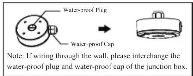
| Cable Entry | Side conduit cabling and cable routing hole |
| Installation Method | Mount base to wall, route cables, attach camera to cover |
| Viewing Angle Adjustment | Yes, after installation (camera can be angled) |
| Included Accessories | Mounting screws, expansion plugs (if needed) |
| Safety Warning | Wall must support 3x combined weight of junction box and camera |
| Maintenance | Periodic check of screws and seals; clean with dry cloth |
| Spare Parts | Screws, covers (available from manufacturer) |
| Warranty | 1 year (typical) |
Frequently Asked Questions - CLT2J Speco Technologies
User questions about CLT2J Speco Technologies
0 question about this device. Answer the ones you know or ask your own.
Ask a new question about this device
Download the instructions for your Unspecified in PDF format for free! Find your manual CLT2J - Speco Technologies and take your electronic device back in hand. On this page are published all the documents necessary for the use of your device. CLT2J by Speco Technologies.
USER MANUAL CLT2J Speco Technologies
natural_image
Technical line drawing of a circular mechanical component with mounting holes and central hub (no text or symbols)Junction Box
Quick Star t Guide
Thank you for purchasing our products. All examples and pictures used in this manual are only for reference purpose. Please take the real object as the standard.
Before installation, make sure that the wall is strong enough to withstand 3 times the weight of the junction box and the camera. We only introduce the installation of some cameras with junction box in this manual.
● Mount the Junction Box and Bullet Camera
- Drill the screw holes on the wall according to the drill template.

natural_image
Pure technical diagram showing a circular component with cross symbol inside, supported by vertical lines (no text or labels)- Push the expansion screws into the screw holes (if the wall is wooden, please skip this step) and then fix the mounting base of the junction box to the wall with screws.

- Reinstall the upper cover to the junction box.

natural_image
Technical line drawing of a mechanical assembly or mounting bracket (no text or symbols)- Open the mounting base and the upper cover of the junction box.

- Fix the mounting base of the camera to the upper cover of the junction box. Then route the cables through the cable hole (take side conduit cabling for example) and connect the cables.

natural_image
Technical line drawing of a mechanical assembly or lifting device (no text or symbols present)- Adjust the view angle of the camera.

natural_image
Technical line drawing of a mechanical assembly with a lever and curved component (no text or symbols)● Mount the Junction Box and Dome Camera (1)
- Drill the screw holes on the wall according to the drill template.

natural_image
Pure electrical circuit lines without any symbols- Secure the mounting base of the junction box to the wall.
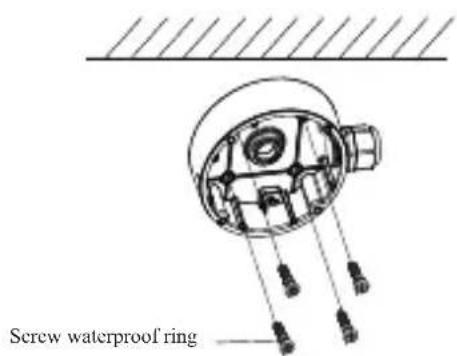
- Route the cables through the cable hole (take side conduit cabling for example) and connect the cables. Then reinstall the upper cover to the junction box.

natural_image
Technical line drawing of a mechanical assembly with internal components and alignment lines (no text or symbols)- Open the mounting base and the upper cover of the junction box.

- Fix the camera to the upper cover of the junction box.

natural_image
Technical line drawing of two mechanical components with mounting holes and connecting rods (no text or symbols)- Adjust the view angle of the camera.
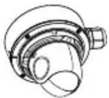
natural_image
Technical line drawing of a mechanical component with no visible text or symbols● Mount the Junction Box and Dome Camera (2)
The step 1 and step 2 are the same as the above-mentioned step 1 and step 2.
- Secure the mounting base of the junction box to the wall.

natural_image
Technical line drawing of a mechanical component with wires and housing (no text or symbols)- Unscrew the lock screw and then remove the mounting base of the camera.
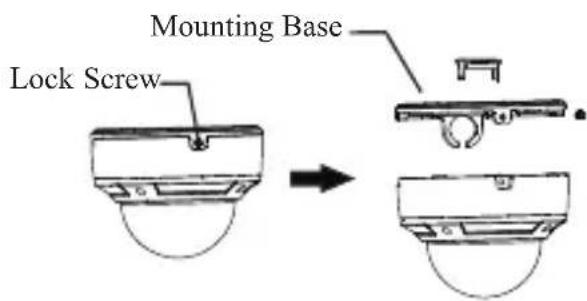
- Connect the cables and then fix the lower dome to the mounting base by tightening the lock screw.

natural_image
Technical diagram of a mechanical assembly with two circular components and a shaft (no text or symbols)- Route the cables through the cable hole (take side conduit cabling for example). Then reinstall the upper cover to the junction box.
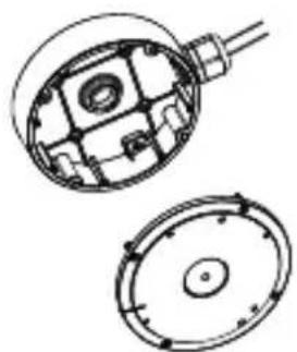
natural_image
Technical line drawing of a mechanical component with cross-sectional and top views (no text or symbols)- Mount the mounting base of the camera to the junction box.

natural_image
Technical line drawing of a mechanical component with two views (top and side), no text or symbols present.- Remove the lower dome to adjust the view angle. After that, reinstall the lower dome to complete the installation.



Brand : Speco Technologies
Model : CLT2J
Category : Unspecified