
O2BLP2M - Unspecified Speco Technologies - Free user manual and instructions
Find the device manual for free O2BLP2M Speco Technologies in PDF.

| Product Type | IP Camera |
| Model | O2BLP2M |
| Image Sensor | 2MP CMOS |
| Resolution | 1920 x 1080 (2MP) |
| Lens Type | Motorized zoom (varifocal) |
| IR Illumination | Integrated IR LEDs |
| Weather Rating | IP67 |
| Power Supply | 12VDC or PoE (IEEE 802.3af) |
| Power Consumption | Not specified (typical ~10W) |
| Video Compression | H.265, H.265+, H.264, H.264+, MJPEG |
| Streaming | Triple stream |
| Day/Night Mode | Auto, Day, Night, Timing |
| WDR (Wide Dynamic Range) | Yes (HWDR) |
| ANPR (License Plate Recognition) | Yes, with vehicle database and comparison |
| Storage | SD card slot (local recording) |
| Audio | Two-way audio (G.711) |
| Alarm Input/Output | Yes (sensor input and alarm out) |
| Network Protocols | TCP/IP, HTTP, RTSP, FTP, SMTP, DDNS, SNMP, QoS |
| Mounting | Outdoor, wall or ceiling mount (accessories included) |
| Compliance | FCC Part 15 |
Frequently Asked Questions - O2BLP2M Speco Technologies
User questions about O2BLP2M Speco Technologies
0 question about this device. Answer the ones you know or ask your own.
Ask a new question about this device
Download the instructions for your Unspecified in PDF format for free! Find your manual O2BLP2M - Speco Technologies and take your electronic device back in hand. On this page are published all the documents necessary for the use of your device. O2BLP2M by Speco Technologies.
USER MANUAL O2BLP2M Speco Technologies
User Manual 2MP License Plate Recognition IP Camera
O2BLP1M/ O2BLP2M
Important Safeguards and Warnings
1. Electrical safety
All installation and operation here should conform to local electrical safety codes.
Use a certified/listed 12VDC Class2 power supply or adequate PoE switch.
Improper handling and/or installation could run the risk of fire or electrical shock.
2. Environment
Do not expose the unit to heavy stress, violent vibration or long-term exposure to water and humidity during transportation, storage, and/or installation.
Do not install near sources of heat.
Only install the product in environments inside the specification operating temperature and humidity range.
Do not install the camera near power lines, radar equipment or other electromagnetic radiation.
Do not block any ventilation openings if any.
Use all the weatherproofing hardware requirement to minimize weather intrusion.
3. Operation and Daily Maintenance
Please shut down the device and then unplug the power cable before you begin any maintenance work.
Do not touch the CMOS sensor optic component. You can use a blower to clean the dust on the lens surface.
Always use the dry soft cloth to clean the device. If there is too much dust, use a cloth dampened with a small quantity of neutral detergent. Finally use the dry cloth to clean the device.
Please use a professional optical cleaning method to clean the enclosure. Improper enclosure cleaning (such as using cloth) may result in poor IR functionality and/or IR reflection.
The grounding holes of the product are recommended to be grounded to further enhance the reliability of the camera.
Dome cover is an optical device, please don't touch or wipe cover surface directly during installation and use, please refer to the following methods if dirt is found.
Stained with dirt:
Use oil-free soft brush or hair dryer to remove it gently.
Stained with grease or fingerprint
Use oil-free cotton cloth or paper soaked with alcohol or detergent to wipe from the lens center outward. Change the cloth and wipe several times if it is not clean enough.
Warning
This camera should be installed by qualified personnel only.
All the examination and repair work should be done by qualified personnel.
Any unauthorized changes or modifications could void the warranty.
Statement
This guide is for reference only.
Product, manuals and specifications may be modified without prior notice. Speco Technologies reserves the right to modify these without notice and without incurring any obligation.
Speco Technologies is not liable for any loss caused by improper operation.
Regulatory Information
FCC conditions:
This device complies with part 15 of the FCC Rules. Operation is subject to the following two conditions:
● This device may not cause harmful interference.
● This device must accept any interference received, including interference that may cause undesired operation.
FCC compliance:
This equipment has been tested and found to comply with the limits for a digital device, pursuant to part 15 of the FCC Rules. These limits are designed to provide reasonable protection against harmful interference. This equipment generates uses and can radiate radio frequency energy and, if not installed and used in accordance with the instruction manual, may cause harmful interference to radio communication. However, there is no guarantee that interference will not occur in a particular installation. If this equipment does cause harmful interference to radio or television reception, which can be determined by turning the equipment off and on, the user is encouraged to try to correct the interference by one or more of the following measures:
● Reorient or relocate the receiving antenna.
- Increase the separation between the equipment and receiver.
- Connect the equipment into an outlet on a circuit different from that to which the receiver is connected.
Note:
Before installation, check the package and make sure that all components are included.
Contact your rep or Speco customer service department immediately if something is broken or missing in the package.
| Accessory name | Amount |
| Network Camera Unit | 1 |
| Quick Start Guide | 1 |
| Installation Accessories Bag | 1 |
| CD | 1 |
Table of Contents
1 Introduction....2
2 Web Access and Login 3
3 Live View 5
4 Camera Configuration 7
4.1 System Configuration....7
4.1.1 System Information 7
4.1.2 Date and Time....7
4.1.3 Local Recording....8
4.1.4 Storage....8
4.2 Video Configuration....10
4.2.1 Image Configuration....10
4.2.2 Video / Audio Configuration....12
4.2.3 OSD Configuration 14
4.2.4 Video Mask 14
4.2.5 ROI Configuration 15
4.2.6 Zoom/Focus 15
4.3 Alarm Setup 16
4.3.1 Motion Detection 16
4.3.2 Other Alarms....17
4.3.3 Alarm In (Sensor Input)....19
4.3.4 Alarm Out 19
4.3.5 Alarm Server 20
4.4 Event Configuration 20
4.4.1 Exception 21
4.4.2 Automatic Number Plate Recognition (ANPR) Settings....22
4.5 Network Configuration 26
4.5.1 TCP/IP 26
4.5.2 Port 27
4.5.3 Server Configuration....27
4.5.4 DDNS....28
4.5.5 SNMP 28
4.5.6 802.1x....29
4.5.7 RTSP 30
4.5.8 RTMP....30
4.5.9 UPNP 31
4.5.10 Email 31
4.5.11 FTP 32
4.5.12 HTTPS....32
4.5.13 HTTP POST 33
4.5.14 QoS....34
4.6 Security Configuration 34
4.6.1 User Admin 34
4.6.2 Online User 36
4.6.3 Block and Allow Lists....36
4.6.4 Security Management....36
4.7 Maintenance Configuration....37
4.7.1 Backup and Restore 37
4.7.2 Reboot 38
4.7.3 Upgrade 38
4.7.4 Operation Log 38
5 Search....39
5.1 Image Search 39
5.2 Video Search....41
5.2.1 Local Video Search....41
5.2.2 SD Card Video Search 42
5.3 Vehicle Data Search 44
Appendix....45
Appendix 1 Troubleshooting....45
1 Introduction
Welcome
Thank you for purchasing this network camera!
Please read this manual carefully before operating the unit and retain it for further reference.
Should you require any technical assistance, please contact Speco Technologies Technical Support.
Main Features
● Built-in PoE (Power over Ethernet)
● Integrated IR LEDs for clear vision in low light
● IP67 rated for outdoor installations
● Remote viewing support via web browser, mobile APP, and VMS
Applications
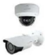
IP Camera

Network

natural_image
Front view of a black laptop computer with blank screen (no visible text or symbols)Web Browser
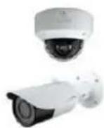
IP Camera

Network or direct connection
NVR
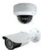
IP Camera

Network

SecureGuard® VMS
2 Web Access and Login
The IP camera settings can be accessed via a web browser through the LAN.
● Access through IP Scanner Network connection:
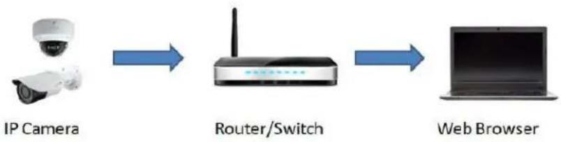
flowchart
graph LR
    A["IP Camera"] --> B["Router/Switch"]
    B --> C["Web Browser"]
① Make sure the PC and IP-Cam are connected on the same local network. The camera is set to DHCP by default and will be assigned an IP address by the DHCP server. Make sure that the local network has a DHCP server. Routers typically have a DHCP server built in.
② Install Speco Blue Scanner and run it after installation. Speco Blue Scanner is the tool for discovering the IP cameras on the local network. It can be downloaded from www.specotech.com.
③ In the device list, the IP address, model number, and MAC address of each device will be listed. Select the applicable device and double click to open up the web viewer. You can also manually enter the IP address in the address bar of the web browser.

The login interface is shown above. Default username is admin and password is 1234. After logging in, follow directions to install applicable plug-ins for viewing video if prompted.
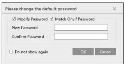
If this is the first time for you to log in, the password prompt may only change the admin password. By default, the ONVIF password will match the admin password that you set. Should you wish to change the ONVIF password to a different password than your admin password, go to the ONVIF section to change the password. (Config→Network→Ports/Connections→Onvif)

3 Live View
The window below will be shown after logging in.

The following table describes the icons on the live view interface
| Icon | Description | Icon | Description |
| Original size | Zoom out | ||
| Fit correct scale | Zoom/Focus control | ||
| Auto (fill the window) | SD card recording indicator | ||
| Full screen | Sensor alarm indicator | ||
| Start/stop live view | Motion alarm indicator | ||
| Start/stop two-way audio | Color abnormal indicator | ||
| Enable/disable audio | Abnormal clarity indicator | ||
| Snapshot | Scene change indicator | ||
| Start/stop local recording | License plate detection | ||
| Zoom in |
● All indicator icons above will flash in live view interface only when the corresponding events are enabled.
- In full screen mode, to exit, double click on the mouse or press the ESC key on the keyboard.
Click the zoom/focus control button to show the control panel. The descriptions of the control panel are as follows:
| Icon | Description | Icon | Description | |
| Zoom - | Zoom + | |||
| Focus - | Focus + | |||
| One key focus (used when image is out of focus after manual adjustment) | ||||
4 Camera Configuration
Press the "Setup" button to go to the configuration interface.
Note: Wherever applicable, click the "Save" button to save the settings.
4.1 System Configuration
4.1.1 System Information
In the "System Information" interface, the system information of the device is listed.

4.1.2 Date and Time
To set the time and date, go to System→Date and Time. Please refer to the following interface.
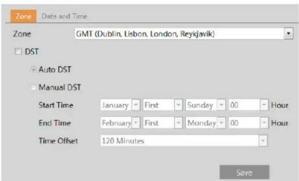
Select the applicable time zone and enable / disable DST as needed.
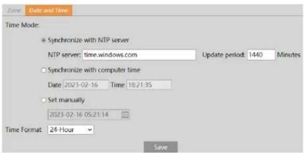
Click the "Date and Time" tab to set the time, date and time format.
4.1.3 Local Recording
Go to System→Local Recording to set up the storage path of captured pictures and recorded videos on the local PC. There is also an option to enable or disable the bitrate display in the recorded files.

Additionally, face snapshots storage can be enabled or disabled here.
Render Mode: High-efficient mode, compatible mode or low-efficient mode can be optional.
For lower performance computers without a dedicated graphics card, the low-efficient mode is suggested.
4.1.4 Storage
Go to System→Storage to go to the interface as shown below.

- SD Card Management
When the card is used for the first time, click the "Format" button to format the SD card. All data on the card will be cleared by clicking this button.
Click the "Eject" button to stop writing data to the SD card. Then the SD card can be ejected safely.
Snapshot Quota: Set the capacity proportion of captured pictures on the SD card.
Video Quota: Set the capacity proportion of record files on the SD card.
- Schedule Recording Settings
- Go to Storage→Record to go to the interface as shown below.
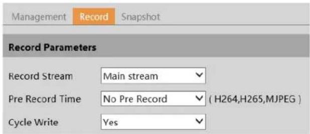
- Set record stream, pre-record time and cycle writing.
Pre Record Time: Set the time to record before the actual recording begins.
- Set schedule recording. Check "Enable Schedule Record" and set the schedule.
Weekly schedule
Set the alarm time from Monday to Sunday for a single week. Each day is divided in one hour increments. Green means scheduled.
Blank means unscheduled.
"Add": Add the schedule for a special day. Drag the mouse to set the time on the timeline.
"Erase": Delete the schedule. Drag the mouse to erase the time on the timeline.
Manual Input: Click it for a specific day to enter specific start and end times. This adds more granularities (minutes).
Day schedule
Set the alarm time for alarm a special day, such as a holiday.
Note: Holiday schedule takes priority over weekly schedule.
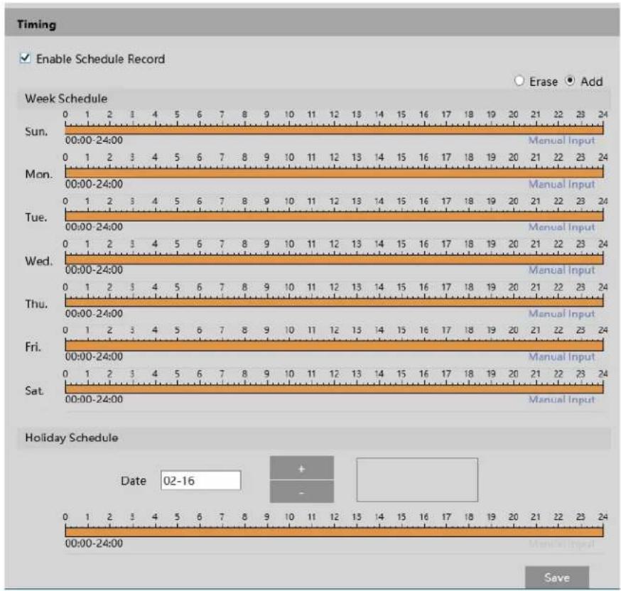
- Snapshot Settings
Go to System→Storage→Snapshot to go to the interface as shown below.
Set the format, resolution and quality of the image saved on the SD card and the snapshot interval and quantity and the timing snapshot here.
Snapshot Quantity: The number you set here is the maximum quantity of snapshots. The actual quantity of snapshots may be less than this number. Supposing the occurrence time of an alarm event is less than the time of capturing pictures, the actual quantity of snapshots is less than the set quantity of snapshots.
Timing Snapshot: Enable timing snapshot first and then set the snapshot interval and schedule. The setup steps of schedule are the same as the schedule recording (See Schedule Recording).
4.2 Video Configuration
Video Configuration includes Image Settings, Video/Audio Setup, OSD, Privacy Mask and Region of Interest.
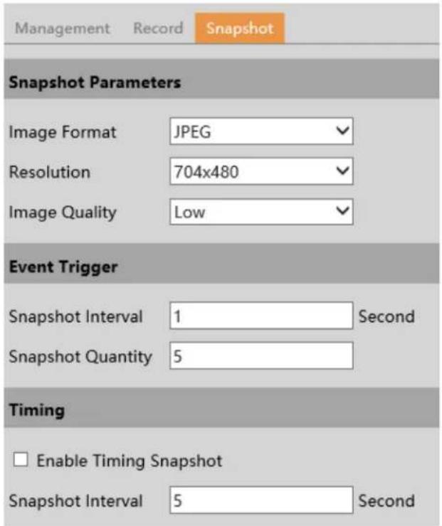
4.2.1 Image Configuration
In the Image Settings interface as shown below, various settings can be adjusted, such as brightness, contrast, hue and saturation and so on. The common mode and day and night mode can be set up separately. The image effect can be quickly viewed by switching the configuration file.
Brightness: Set the brightness level of the camera's image.
Contrast: Set the color difference between the brightest and darkest parts.
Hue: Set the total color degree of the image.
Saturation: Set the degree of color purity. The purer the color, the brighter the image is.
Sharpness: Set the resolution level of the image plane and the sharpness level of the image edge.
Noise Reduction: Decrease the noise and make the image more thorough. Increasing the value will make the noise reduction effect better but it will reduce the image resolution.
Defog: Activating this function and setting an appropriate value as needed in foggy, dusty, smoggy or rainy environment to get clear images.
Auto Iris: If your camera is auto Iris, please enable it.
Backlight Compensation (BLC):
- Off: disables the backlight compensation function. It is the default mode.
- HWDR: WDR can adjust the camera to provide a better image when there are both very bright and very dark areas simultaneously in the field of the view by lowering the brightness of the bright area and increasing the brightness of the dark area. Recording will be stopped for a few seconds while the mode is changing from non-WDR to WDR mode.
- HLC: lowers the brightness of the entire image by suppressing the brightness of the image's bright area and reducing the size of the halo area.
- BLC: If enabled, the auto exposure will activate according to the scene so that the object of the image in the darkest area will be seen clearly.
HFR: High Frame Rate. If "ON" is selected, the system will restart and then the maximum value of the frame rate of the main stream can be set to 60 fps /50fps.
Antiflicker:
- Off: disables the anti-flicker function. This is used mostly in outdoor installations.
- 50Hz: reduces flicker in 50Hz lighting conditions.
- 60Hz: reduces flicker in 60Hz lighting conditions.
Smart IR: Choose "ON" or "OFF". This function can effectively avoid image overexposure and underexposure by controlling the brightness of the IR lights according to the actual conditions to make the image more realistic. Please enable it as needed.
White Balance: Adjust the color temperature according to the environment automatically.
Day/Night Mode: Choose "Auto", "Day", "Night" or "Timing".
Shutter Mode: Choose "Auto" or "Manual". If manual is chosen, the digital shutter speed can be adjusted.
Gain Mode: Choose "Auto" or "Manual". If "Auto" is selected, the gain value will be automatically adjusted according to the actual situation. If "Manual" is selected, the gain value shall be set manually. The higher the value is, the brighter the image is.
Frequency: 50Hz and 60Hz can be optional.
Infra-red Mode: Choose "Auto", "ON" or "OFF".
Image Mirror: Turn the current video image horizontally.
Image Flip: Turn the current video image vertically.
Schedule Settings of Image Parameters:
Click the "Profile Management" tab as shown below.

Set full time schedule for common, day or night mode and specified time schedule for day and night. Choose "Timing" in the drop-down box of schedule as shown below.
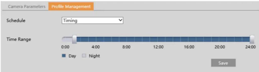
Drag “☐” icons to set the time of day and night. Blue means day time and blank means night time. If the current mode of camera parameters is set to “Timing”, the image configuration mode will automatically switch between day and night according to the schedule.
4.2.2 Video / Audio Configuration
Go to Image→Video / Audio interface as shown below. In this interface, set the resolution, frame rate, bitrate type, video quality and so on subject to the actual network condition.

Three video streams can be adjustable.
Resolution: The size of image.
Frame rate: The higher the frame rate, the video is smoother.
Bitrate type: CBR and VBR are optional. Bitrate is related to image quality. CBR means that no matter how much change is seen in the video scene, the compression bitrate will be kept constant. VBR means that the compression bitrate will be adjusted according to scene changes. For example, for scenes that do not have much movement, the bitrate will be kept at a lower value. This can help optimize the network bandwidth usage.
Bitrate: it can be adjusted when the mode is set to CBR. The higher the bitrate, the better the image quality will be.
Video Quality: It can be adjusted when the mode is set to VBR. The higher the image quality, the more bitrate will be required.
I Frame interval: It determines how many frames are allowed between a “group of pictures”. When a new scene begins in a video, until that scene ends, the entire group of frames (or pictures) can be considered as a group of pictures. If there is not much movement in the scene, setting the value higher than the frame rate is fine, potentially resulting in less bandwidth usage. However, if the value is set too high, and there is a high frequency of movement in the video, there is a risk of frame skipping.
Video Compression: MJPEG, H264+, H264, H264S (Smart H.264), H265, H265+ or H265S (Smart H.265) can be optional. MJPEG is not available for main stream. If H.265/H.265+/H.265S is chosen, make sure the client system is able to decode H.265/H.265+/H.265S. Compared to H.265+/H.265, smart H.265 (H.265S) can spontaneously adjust the bitrate distribution according to the requirements of the actual scene. For example, when there is no vehicle detected, the bitrate will be automatically reduced with no effect on image quality by using H.265S. Compared to H.265, H.265+ saves more storage space with the same maximum bitrate in most scenes.
Compared to H.264, H.265 reduces the transmission bitrate under the same resolution, frame rate and image quality.
Profile: For H.264. Baseline, main and high profiles are selectable.
Send Snapshot: How many snapshots to generate for an event.
Video encode slice split: If this function is enabled, smooth image can be gotten even though using the low-performance PC.
Watermark: When playing back the local recorded video in the search interface, the watermark can be displayed. To enable it, check the watermark box and enter the watermark text.
Click the "Audio" tab to go to the interface as shown below.
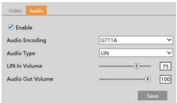
Audio Encoding: G711A and G711U are selectable.
Audio Type: LIN.
4.2.3 OSD Configuration
Go to Video→OSD interface as shown below.

Set time stamp, device name, OSD content and picture overlap here. After enabling the corresponding display and entering the content, drag them to change their position. Then click the "Save" button to save the settings.
Picture Overlap Settings:
Check "OSD Content1", choose "Picture Overlay" and click "Browse" to select the overlap picture. Then click "Upload" to upload the overlap picture. The pixel of the image shall not exceed 200*200, or it cannot be uploaded.
4.2.4 Video Mask
Go to Image→Video Mask interface as shown below. A maximum of 4 zones can be set up.
To set up video mask:
- Enable video mask.
- Click the "Draw Area" button and then drag the mouse to draw the video mask area.
- Click the "Save" button to save the settings.
- Return to the live to verify that the area have been drawn as shown as blocked out in the image.
natural_image
Two blue and white cars driving on a multi-lane road, captured in aerial view with no visible text or symbols.To clear the video mask:
Click the "Clear" button to delete the current video mask area.
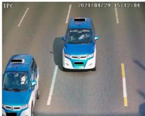
4.2.5 ROI Configuration
Go to Image→ROI Config interface as shown below. An area in the image can be set as a region of interest. This area will have a higher bitrate than the rest of the image, resulting in better image quality for the identified area.
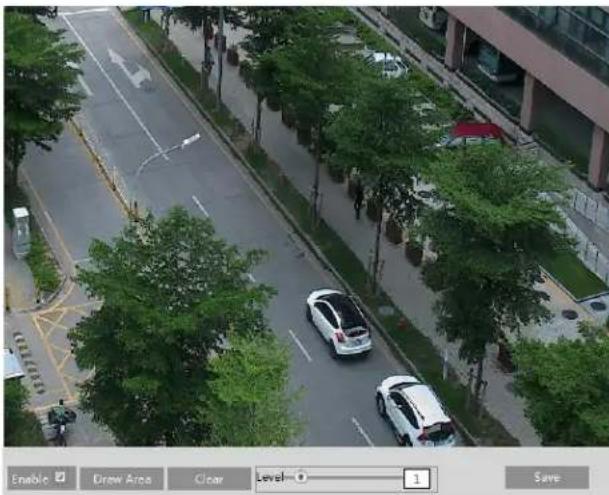
natural_image
Aerial view of a city street with parked cars and trees, no visible text or symbols.- Check "Enable" and then click the "Draw Area" button.
- Drag the mouse to set the ROI area.
- Set the level.
- Click the "Save" button to save the settings.

natural_image
Aerial view of a tree-lined road with two cars driving along the sidewalk (no visible text or signage)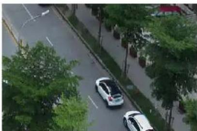
natural_image
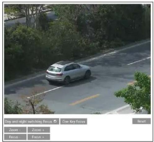
Aerial view of a tree-lined road with two cars, no visible text or signage4.2.6 Zoom/Focus
This function is only available for the model with motorized zoom lens. Within this section, zoom and focus can be controlled. If the image is out of focus after a manual adjustment, one key focus can be used to set the focus automatically.
4.3 Alarm Setup
4.3.1 Motion Detection
Go to Alarm → Motion Detection to set motion detection alarm.
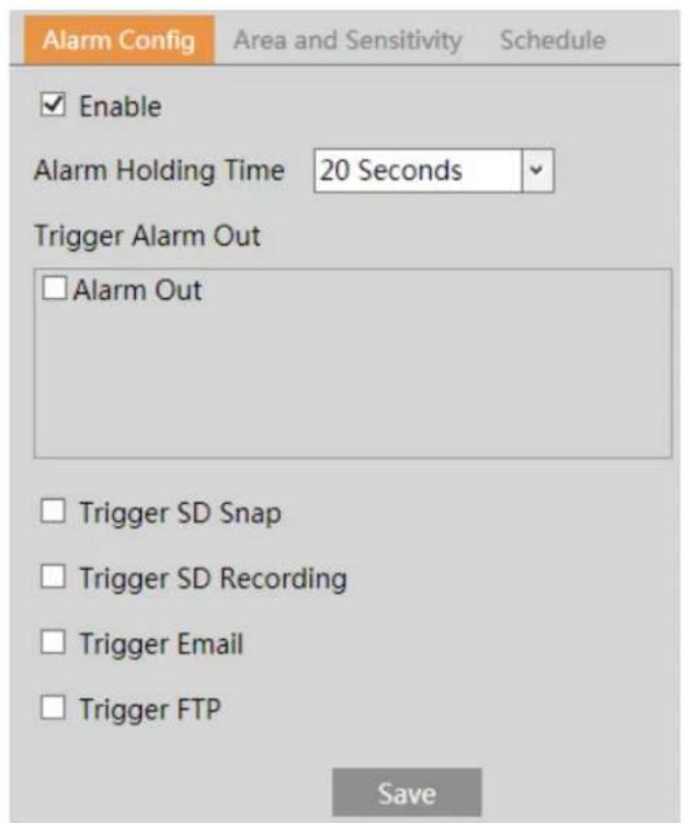
- Check "Enable" check box to activate motion based alarms. If unchecked, the camera will not send out any signals to trigger motion-based recording to the NVR or CMS, even if there is motion in the video.
Alarm Out: If selected, this would trigger an external relay output that is connected to the camera on detecting a motion based alarm.
Trigger Snapshot: If selected, the system will capture images on motion detection and save the images on an SD card.
Trigger SD Recording: If selected, video will be recorded on an SD card on motion detection.
Trigger Email: If "Trigger Email" and "Attach Picture" are checked (email address must be set first in the Email configuration interface), the captured pictures and triggered event will be sent into those addresses.
Trigger FTP: If "Trigger FTP" and "Attach Picture" are checked, the captured pictures will be sent into FTP server address. Please
refer to FTP configuration chapter for more details.
- Set motion detection area and sensitivity. Click the "Area and Sensitivity" tab to go to the interface as shown below.
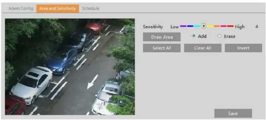
Move the "Sensitivity" scroll bar to set the sensitivity. Higher sensitivity value means that motion will be triggered more easily. Select "Add" and click "Draw". Drag the mouse to draw the motion detection area; Select "Erase" and drag the mouse to clear motion detection area.
After that, click the "Save" to save the settings. "Clear All" can be used to clear out the entire motion zone.
- Set the schedule for motion detection. The schedule setup steps of the motion detection are the same as the schedule recording setup (See Schedule Recording).
4.3.2 Other Alarms
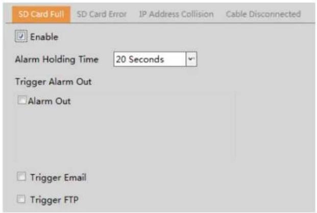
SD Card Full
- Go to Alarm → Anomaly → SD Card Full.
-
Click "Enable" and set the alarm holding time.
-
Set alarm trigger options. The setup steps are the same as motion detection. Please refer to motion detection chapter for details.
- SD Card Error
When there are some errors in writing SD card, the corresponding alarms will be triggered.
- Go to Event Setup → Anomaly → SD Card Error as shown below.
- Click "Enable" and set the alarm holding time.
- Set alarm trigger options. Trigger alarm out, Email and FTP. The setup steps are the same as motion detection. Please refer to motion detection chapter for details.
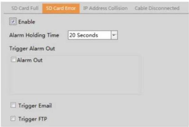
IP Address Conflict
This function is only available for the models with Alarm Out interface.
- Go to Alarm → Anomaly → IP Address Collision as shown below.

- Click "Enable alarm" and set the alarm holding time.
- Trigger alarm out. When the IP address of the camera is in conflict with the IP address of other devices, the system will trigger the alarm out.
- Cable Disconnection
This function is only available for the models with Alarm Out interface.
- Go to Alarm → Anomaly → Cable Disconnected as shown below.
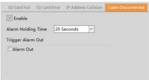
- Click "Enable" and set the alarm holding time.
- Trigger alarm out. When the camera is disconnected, the system will trigger the alarm out.
4.3.3 Alarm In (Sensor Input)
This function is only available for some models. To set sensor alarm (alarm in):
Go to Alarm→Alarm In interface as shown below.

-
Click "Enable" and set the alarm type, alarm holding time and sensor name.
-
Set alarm trigger options.
Day/night switch linkage: if enabled, daytime mode or night mode can be triggered as needed.
The setup steps of other alarm trigger options are the same as motion detection. Please refer to motion detection chapter for details.
-
Click "Save" button to save the settings.
-
Set the schedule of the sensor alarm. The setup steps of the schedule are the same as the schedule recording setup. (See Schedule Recording).
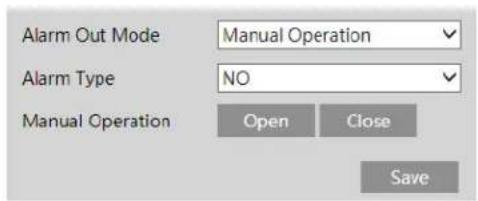
4.3.4 Alarm Out
This function is only available for some models. Go to Alarm→Alarm Out.
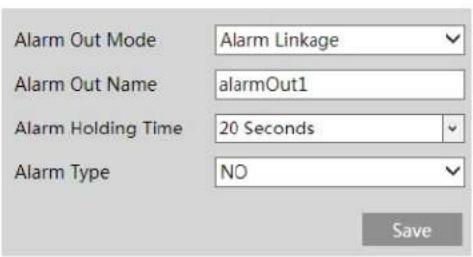
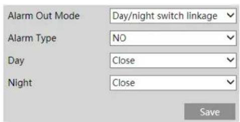
Alarm Out Mode: Alarm linkage, manual operation, day/night switch linkage and timing are optional.
Alarm Linkage: Having selected this mode, select alarm out name, alarm holding time at the "Alarm Holding Time" pull down list box and alarm type.
Manual Operation: Having selected this mode, select the alarm type and click "Open" to trigger the alarm out immediately; click "Close" to stop alarm.
Day/Night Switch Linkage: Having selected this mode, select the alarm type and then choose to open or close alarm out when the camera switches to day mode or night mode.
Timing: Select the alarm type. Then click "Add" and drag the mouse on the timeline to set the schedule of alarm out; click "Erase" and drag the mouse on the timeline to erase the set time schedule. After this schedule is saved, the alarm out will be triggered in the specified time.

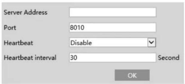
4.3.5 Alarm Server
Go to Alarm→Alarm Server interface as shown below.
Set the server address, port, heartbeat and heartbeat interval. When an alarm occurs, the camera will transfer the alarm event to the alarm server. If an alarm server is not needed, there is no need to configure this section.
4.4 Event Configuration
For more accuracy, here are some recommendations for installation.
- Cameras should be installed on stable surfaces, as vibrations can affect the accuracy of detection.
- Avoid pointing the camera at the reflective surfaces (like shiny floors, mirrors, glass, lake surfaces and so on).
- Avoid places that are narrow or have too much shadowing.
- Avoid scenario where the object's color is similar to the background color.
- At any time of day or night, please make sure the image of the camera is clear and with adequate and even light, avoiding
overexposure or too much darkness on both sides.
4.4.1 Exception
This function can detect changes in the surveillance environment affected by the external factors.
Go to Event→Exception interface as shown below.
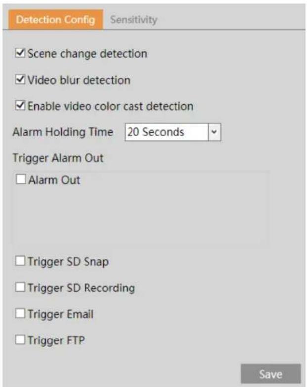
- Enable the applicable detection that's desired.
Scene Change Detection: Alarms will be triggered if the scene of the video has changed.
Video Blur Detection: Alarms will be triggered if the video becomes blurry.
Enable Video Color Cast Detection: Alarms will be triggered if the video becomes obscured.
- Set the alarm holding time and alarm trigger options. The setup steps are the same as motion detection. Please refer to motion detection chapter for details.
- Click "Save" button to save the settings.
- Set the sensitivity of the exception detection. Click "Sensitivity" tab to go to the interface as shown below.

Drag the slider to set the sensitivity value or directly enter the sensitivity value in the textbox. Click "Save" button to save the settings.
The sensitivity value of Scene Change Detection: The higher the value is, the more sensitive the system responds to the amplitude of the scene change.
The sensitivity value of Video Blur Detection: The higher the value is, the more sensitive the system responds to the blurriness of the image.
The sensitivity value of Video Color Cast Detection: The higher the value is, the more sensitive the system responds to the obscuring of the image.
※ The requirements of camera and surrounding area
- Auto-focusing function should not been enabled for exception detection.
- Try not to enable exception detection when light changes greatly in the scene.
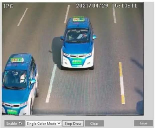
4.4.2 Automatic Number Plate Recognition (ANPR) Settings
ANPR function is to detect and compare license plate numbers. Alarms will be triggered when a license plate is detected. The setting steps of vehicle license plate detection and comparison are as follows:
- Go to Config→Event→ANPR as shown below.
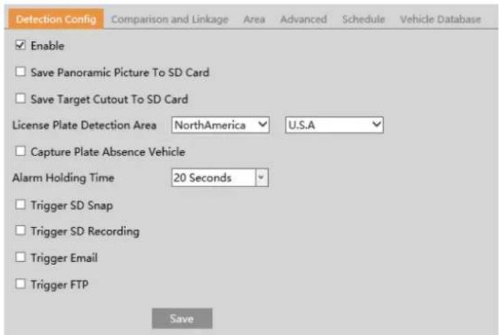
- Enable ANPR. Select Save Original Picture/Target Picture to SD Card, License Plate Detection Area, and Capture Plate Absence Vehicle as needed.
Set alarm holding time and alarm trigger options. The alarm trigger setup steps are the same as motion detection setup. Please refer to motion detection chapter for details.
- Set the alarm detection area and the blocked area.
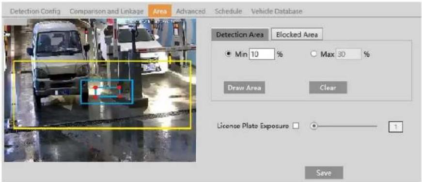
To set the detection area:
Click "Draw Area" and drag the border lines of the rectangle to modify its size. Click "Stop Draw" to stop drawing the area. Click "Clear" to clear the area. Then set the detectable size by defining the maximum value and the minimum value (The default size range of a single number plate image occupies from 5% to 50% of the entire image).
To set the blocked area
Select the number of the undetected area. Then click "Draw Area" to draw a closed area. Up to 4 areas can be set up. After you set the blocked area, this area will not be detected.
License Plate Exposure: Set the exposure weight of the license plate in license plate exposure compensation mode. When detecting a license plate in the detection area, the camera will automatically adjust the brightness of the set plate detection area according to
the exposure weight. The higher the value is, the higher the exposure weight is.
When the brightness of the captured license plate is not enough or the plate overexposure happens, it can be enabled. Please check and set license plate exposure as needed.
-
Set the schedule of the ANPR. The setup steps of the schedule are the same as schedule recording setup (See Schedule Recording).
-
Add vehicles to the vehicle Database. Click the vehicle database tab to go to the following interface.
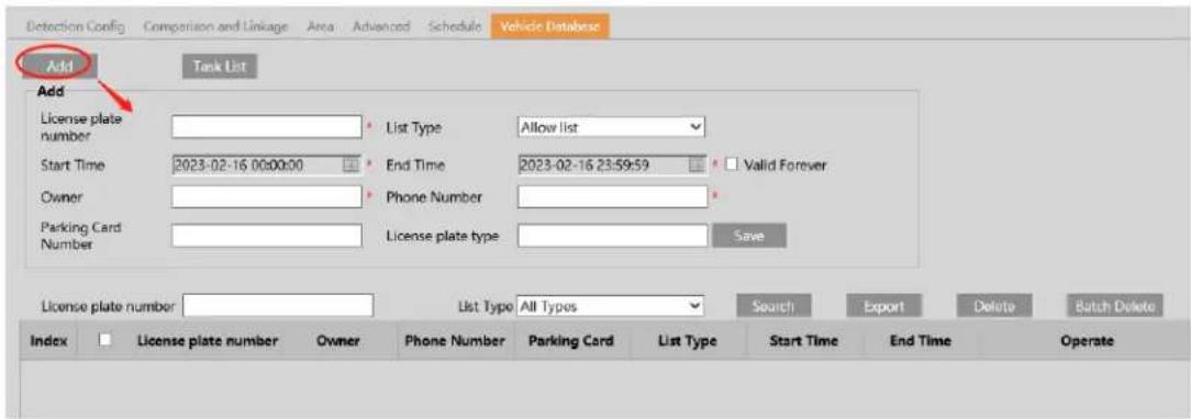
- Add vehicles
Click "Add" to show a vehicle adding box as shown in the above figure. Enter the license plate number, select list type, start and end time, enter owner and license plate type. Then click "Save" to save the vehicle.
List type: temporary vehicle, allow list and block list can be selected.
Click "Task List" to add multiple vehicles at one time as shown below.
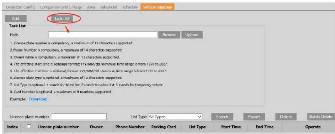
Please edit the vehicle information according to the requirements shown on the above interface. If you don't know how to edit the file, please click "Download" to download an example file and then follow the example to edit. After that, click "Browse" to choose the vehicle information file and click "Upload" to import all vehicle information.
- Search vehicles
After the vehicles are added, you can search them in the vehicle list. Enter the license plate number and list type and then click "Search" to search the added vehicle information. Click "Modify" to modify its information. Click "Delete" to delete this vehicle information.
- Set the license plate comparison and alarm linkage. Click the "Comparison and linkage" tab to go to the following interface.
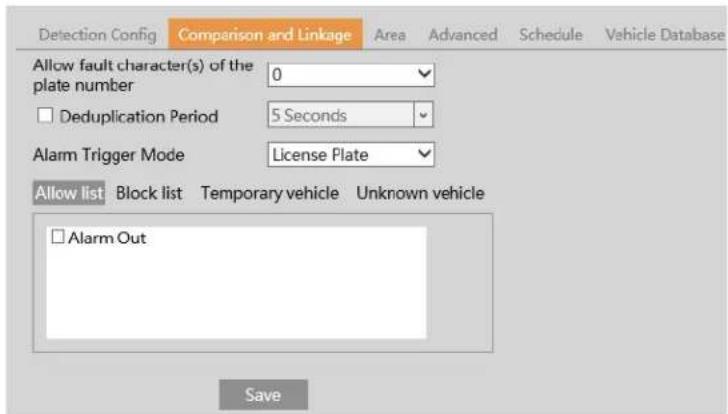
Set the fault tolerance, alarm list and check "alarm out". Finally, click "Save" to save all the settings.
Allow fault character(s) of the plate number: up to 2 characters are allowed. For example, if "2" is selected, the captured license plate will be matched successfully and trigger the corresponding alarm even if there are 2 characters (or less) of the captured license plate not matched with the license plate of the vehicle list.
Deduplication Period: In the set period, delete the repeated comparison results.
Alarm Trigger Mode: "License Plate" or "License Plate and Parking Card".
Note: Only the model with the wiegand interface supports the "License Plate and Parking Card" mode and the wiegand interface has been connected to the card reader as wiegand input.
Alarm Output: Select the list type and then checkmark alarm out. Then the alarm output will be triggered when the captured plate number is matched successfully with the plate number of the selected list. If you check the alarm out of the unknown vehicle, the alarm output will be triggered once unknown vehicles (unregistered vehicles) are captured. If "No Plate" is selected, the alarm output will be triggered once the vehicles without license plate are captured.
Wiegand Output: Select the list type and then checkmark wiegand output. Then the wiegand output will be triggered when the captured plate number is matched successfully with the plate number of the selected list. (Only the model with the wiegand interface supports this function)
- Advanced Settings. Click the "Advanced" tab to go to the following interface.

Recognition Mode: All, Recognizing when approaching, Recognizing when driving away.
Tolerant Digitals: please set the tolerant character pair as needed. For example: 1 and L, supposing that the plate number "ABCL" has been added to the vehicle database, when the plate number "ABC1" is detected by the camera, then these two plate numbers will be matched successfully, and vice versa.
Multiple tolerant digital pairs can be set as needed.
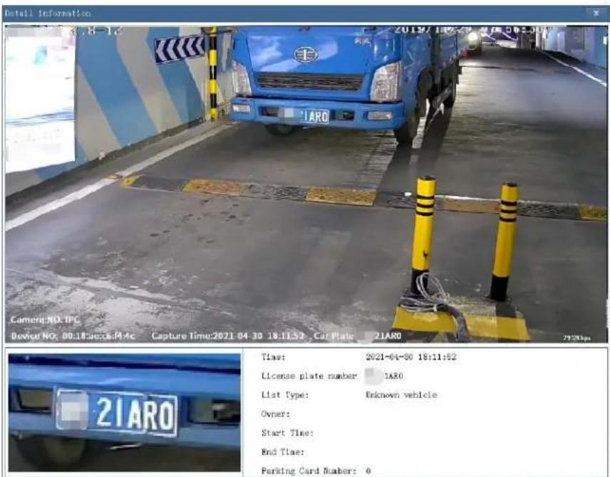
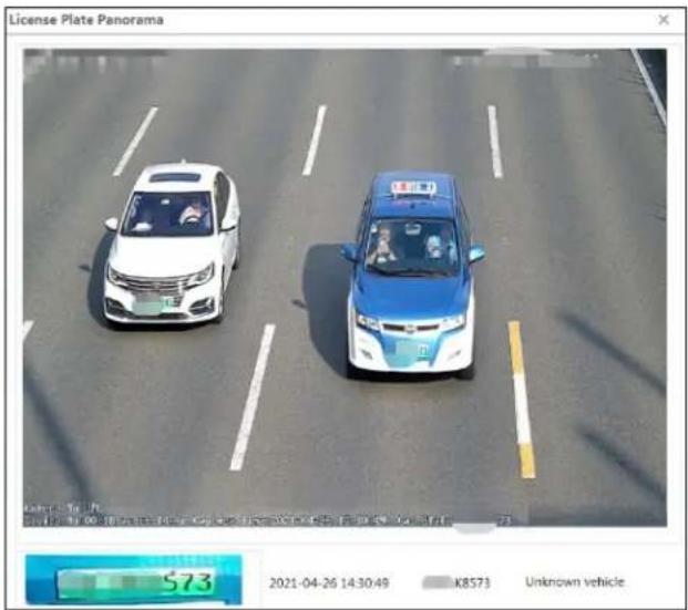
After all above information are set, go to the live interface and click 📄 to see the captured pictures as shown below.

When the captured license plate is matched with the license plate of the vehicle database, the list type will be displayed under the license plate number. Click the matched license plate picture, the matched details will pop up as shown below.
※ Configuration requirements of camera and surrounding area
Note: The following installation requirements are based on optimum conditions, your license capture rate may vary depending on lighting, position, license plate designs and other factors.
- The monitoring image shall try to cover the lane, entering/exiting vehicles and these vehicles' plate number shall be always seen in the video.
- Try to avoid the objects that will block the camera, such as pillars, obstacles, doors, etc.
- Avoid the scenes with many trees or other moving objects (like humans, non-motor vehicles).
- The monitoring road shall be straight within 165ft in front of/behind the location of the camera installation and make sure the camera points at the front or rear of the vehicle.
The recommended installation height and distance are as follows:
| Overhead | Entrance/Exit | |||
| Lens Type | Recommended Installation Height(H) | Recommended Recognition Distance(L) | Recommended Installation Height(H) | Recommended Recognition Distance(L) |
| 7-22mm | 15-20ft | 23-98ft | 4.2-5ft | 8-10ft |
| 5-50mm | 13-20ft | 16-164ft | 4.2-5ft | 8-10ft |
| 8-32mm | 15-20ft | 23-115ft | 4.2-5ft | 8-10ft |
The tilt angle of the license plate
After the camera is installed, you can log in the web client and view whether the license plate tilts in the video. The tilt angle shall range from -5^ to 5^ .

If the captured license plate doesn't meet the above requirement, you can adjust the pan angle of the camera to correct it.
4.5 Network Configuration
4.5.1 TCP/IP
Go to Network→TCP/IP interface as shown below. There are two ways for network connection.

Use IP address (take IPv4 for example)-obtain a local IP address automatically through DHCP. A typical router has a DHCP server built in, and therefore is able to assign an IP address to the camera.
Use PPPoE-Click the "PPPoE Config" tab to go to the interface as shown below. Enable PPPoE and then enter the user name and password from your ISP.
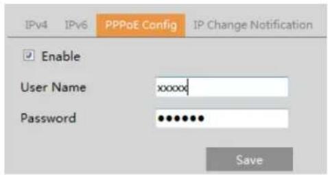
Either method of network connection can be used. If PPPoE is used to connect internet, the camera will get a dynamic WAN IP address. This IP address will change frequently. To be notified, the IP change notification function can be used.
Click "IP Change Notification Config" to go to the interface as shown below.
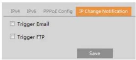
Trigger Email: when the IP address of the device is changed, the new IP address will be sent to the email address that has been set up.
Trigger FTP: when the IP address of the device is changed, the new IP address will be sent to FTP server that has been set up.
4.5.2 Port
Go to Network→Port/Connections interface as shown below. HTTP port, Data port and RTSP port can be set.

HTTP Port: The default HTTP port is 80. It can be changed to any port which is not occupied.
HTTPS Port: The default HTTPS port is 443. It can be changed to any port which is not occupied.
Data Port: The default data port is 9008. Please change it as necessary.
RTSP Port: The default port is 554. Please change it as necessary.
Persistent Connection Port: The port is used for a persistent connection of the third-party platform to push smart data, like face pictures.
WebSocket Port: Communication protocol port for plug-in free preview.
4.5.3 Server Configuration
This function is mainly used for connecting network video management system.
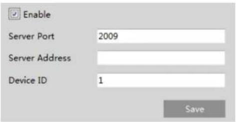
- Check "Enable".
- Check the IP address and port of the transfer media server in the VMS. Then enable the auto report in the VMS when adding a new device. Next, enter the remaining information of the device in the VMS. After that, the system will automatically allot a device ID. Please check it in the VMS.
- Enter the above-mentioned server address, server port and device ID in the corresponding boxes. Click the "Save" button to save the settings.
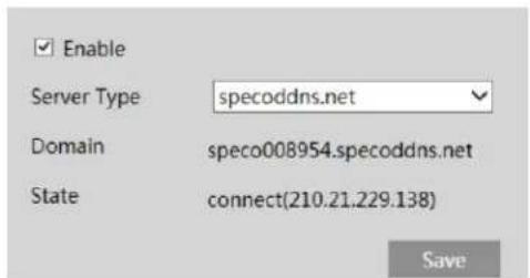
4.5.4 DDNS
If the camera is set up with a DHCP connection, DDNS should be set for accessing the camera from the internet.
- Go to Network→DDNS.
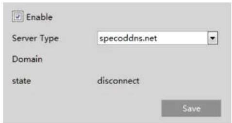
- Enable, save and use DDNS to log in.
4.5.5 SNMP
To get camera status, parameters and alarm information and remotely manage the camera, the SNMP function can be used. Before using SNMP, please install an SNMP management tool and set the parameters of the SNMP, such as SNMP port, trap address.
- Go to Network→SNMP.
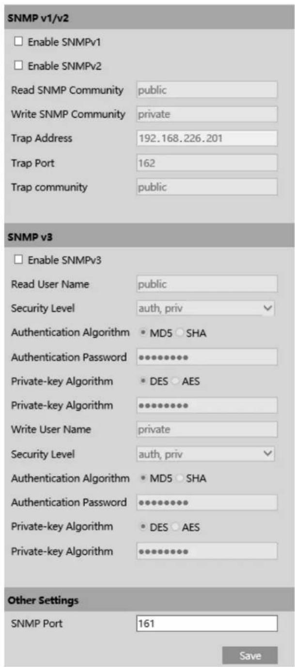
- Check the corresponding version checkbox (Enable SNMPv1, Enable SNMPv2, Enable SNMPv3) according to the version of the SNMP software that will be used.
- Set the values for "Read SNMP Community", "Write SNMP Community", "Trap Address", "Trap Port" and so on. Please make sure the settings are the same as that of the SNMP software.
4.5.6 802.1x
If it is enabled, the camera's data can be protected. When the camera is connected to the network protected by the IEE802.1x, user authentication is needed.

To use this function, the camera shall be connected to a switch supporting 802.1x protocol. The switch can be reckoned as an authentication system to identify the device in a local network. If the camera connected to the network interface of the switch has passed the authentication of the switch, it can be accessed via the local network.
Protocol type and EAPOL version: Please use the default settings.
User name and password: The user name and password must be the same with the user name and password applied for and registered in the authentication server.
4.5.7 RTSP
Go to Network→RTSP.
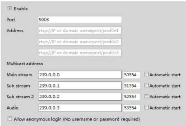
Select "Enable" to enable the RTSP function.
Port: Access port of the streaming media. The default number is 554.
RTSP Address: The RTSP address (unicast) format that can be used to play the stream in a media player.
Multicast Address
Main stream: The address format is
"rtsp://IP address: rtsp port/profile1?transportmode=mcast".
Sub stream: The address format is
"rtsp://IP address: rtsp port/profile2?transportmode=mcast".
Third stream: The address format is
"rtsp://IP address: rtsp port/profile3?transportmode=mcast".
Audio: Having entered the main/sub stream in a media player(like VLC), the video and audio will play automatically.
If "Allow anonymous login..." is checked, there is no need to enter the username and password to view the video.
If "auto start" is enabled, the multicast received data should be added into a VLC player to play the video.
4.5.8 RTMP
You can access the third-party (like YouTube) to realize video live view through RTMP protocol.
Go to Config→Network→RTMP.
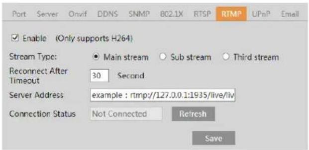
Check "Enable", select stream type, set the reconnection time after timeout and server address as needed.
Server address: Enter the server address allocated by the third party server.
After that, click "Save" to save the settings. Then click "Refresh" to view the connection status.
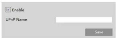
4.5.9 UPNP
If this function is enabled, the camera can be quickly accessed through the LAN.
Go to Network→UPnP. Enable UPNP and then enter UPnP name.
4.5.10 Email
If you need to trigger Email when an alarm happens or IP address is changed, please set the Email here first.
Go to Network → Email.
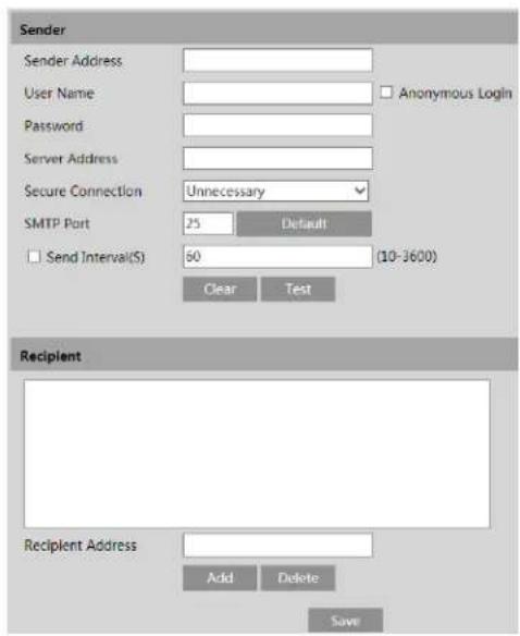
Sender Address: sender's e-mail address.
User name and password: sender's user name and password (you don't have to enter the username and password if "Anonymous Login" is enabled).
Server Address: The SMTP IP address or host name.
Select the secure connection type at the "Secure Connection" pull-down list according to what's required.
SMTP Port: The SMTP port.
Send Interval(S): The time interval of sending email. For example, if it is set to 60 seconds and multiple motion detection alarms are triggered within 60 seconds, they will be considered as only one alarm event and only one email will be sent. If one motion alarm event is triggered and then another motion detection alarm event is triggered after 60 seconds, two emails will be sent. When
different alarms are triggered at the same time, multiple emails will be sent separately.
Click the "Test" button to test the connection of the account.
Recipient Address: receiver's e-mail address.
4.5.11 FTP
After an FTP server is set up, captured pictures from events will be uploaded to the FTP server.
Go to Network → FTP.
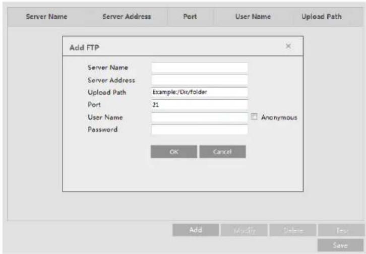
Server Name: The name of the FTP server.
Server Address: The IP address or domain name of the FTP.
Upload Path: The directory where files will be uploaded to.
Port: The port of the FTP server.
Use Name and Password: The username and password that are used to login to the FTP server.
4.5.12 HTTPS
HTTPS provides authentication of the web site and protects user privacy.
Go to Network→HTTPS as shown below.
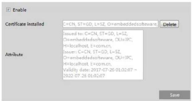
There is a certificate installed by default as shown above. Enable this function and save it. Then the camera can be accessed by entering https://IP: https port via the web browser (eg. https://192.168.226.201:443).
A private certificate can be created if users don't want to use the default one. Click "Delete" to cancel the default certificate. Then the following interface will be displayed.

* If there is a signed certificate, click "Browse" to select it and then click "Install" to install it.
* Click "Create a private certificate" to enter the following creation interface.

Click the "Create" button to create a private certificate. Enter the country (only two letters available), domain (camera's IP address/domain), validity date, password, province/state, region and so on. Then click "OK" to save the settings.
* Click "Create a certificate request" to enter the following interface.
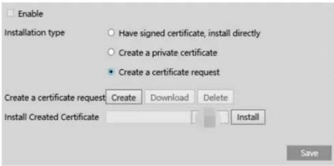
Click "Create" to create the certificate request. Then download the certificate request and submit it to the trusted certificate authority for signature. After receiving the signed certificate, import the certificate to the device.
4.5.13 HTTP POST
Go to Config→Network→HTTP POST interface.
Check "Enable", select protocol type and then set the server address (IP address/domain name), server port, heartbeat interval.
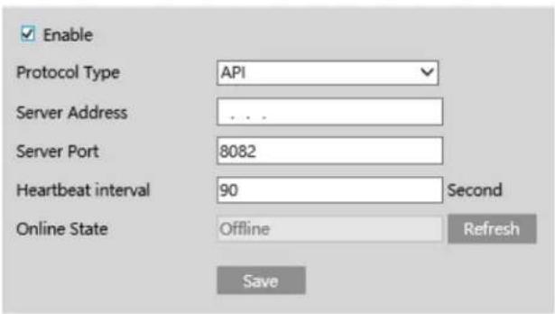
Server address: the IP address/domain name of the third-party platform.
Server port: the server port of the third-party platform.
After the above parameters are set, click "Save" to save the settings. Then the camera will automatically connect the third-party platform. The online state can be viewed in the above interface. After the camera is successfully connected, it will send the alarm information (HTTP format) to the third-party platform once the smart alarm is triggered. The alarm information includes target tracing coordinates, target features, the captured original/target image (like the captured license plate picture) and so on.
4.5.14 QoS
QoS (Quality of Service) function is used to provide different quality of services for different network applications. With the deficient bandwidth, the router or switch will sort the data streams and transfer them according to their priority to solve the network delay and network congestion by using this function.
Go to Network→QoS.
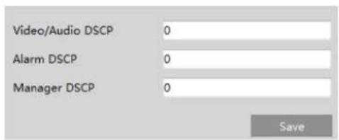
Video/Audio DSCP: The range is from 0 to 63.
Alarm DSCP: The range is from 0 to 63.
Manager DSCP: The range is from 0 to 63.
Generally speaking, the larger the number is, the higher the priority is.
4.6 Security Configuration
4.6.1 User Admin
Go to Security→User Admin interface as shown below.

Add user:
- Click "Add" to pop up the following textbox.
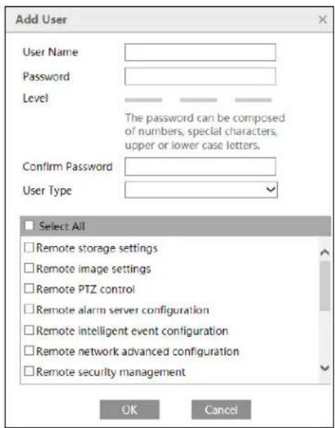
- Enter user name in "User Name" textbox.
- Enter letters or numbers in "Password" and "Confirm Password" textbox. Please set the password according to the requirement of the password security level (Go to Setup→Security→Security Management→Password Security interface to set the security level).
- Choose the user type and select the permission.
- Click the "OK" button and then the newly added user will be displayed in the user list.
Modify user:
- Select a user to modify password and MAC address if necessary in the user configuration list box.
- The "Edit user" dialog box pops up by clicking the "Modify" button.
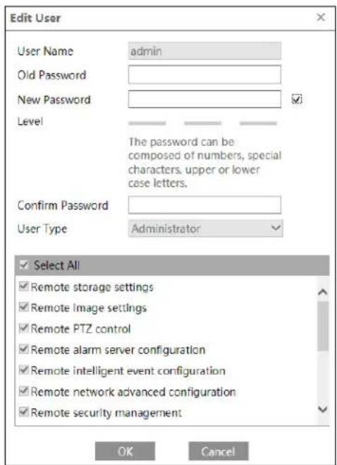
- Enter the old password of the user in the "Old Password" text box.
- Enter the new password in the "New password" and "Confirm Password" text box.
- Modify the permission as necessary.
- Click the "OK" button to save the settings.
Note: To change the access level of a user, the user must be deleted and added again with the new access level.
Delete user:
- Select the user to be deleted in the user configuration list box.
- Click the "Delete" button to delete the user.
Note: The default administrator account cannot be deleted.
4.6.2 Online User
Go to Security→Online User to view the user who is viewing the live video.
| Index | Client Address | Port | User Name | User Type | |
| 1 | 192.168.17.232 | 55760 | admin | Administrator | Kick Out |
An administrator user can kick out all the other users (including other administrators).
4.6.3 Block and Allow Lists
Go to Security→Block and Allow Lists as shown below.

The setup steps are as follows:
Check the "Enable address filtering" check box.
Select "Block/Allow the following address", IPv4/IPv6 and then enter IP address in the address box and click the "Add" button.
4.6.4 Security Management
Go to Security→Security Management as shown below.

In order to prevent against malicious password unlocking, "locking once illegal login" function can be enabled here. If this function is enabled, login failure after trying five times will make the login interface locked. The camera can be logged in again after a half hour or after the camera reboots.
Trigger Email: if enabled, e-mail will be sent when logging in/out or illegal login lock occurs.
Logout time: Set the logout time as needed. For example: 3600s, you will be automatically logged out after 3600s and then you need to enter the username and password again to log in.
- Password Security
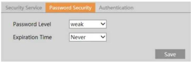
Please set the password level and expiration time as needed.
Password Level: Weak, Medium or Strong.
Weak level: Numbers, special characters, upper or lower case letters can be used. You can choose one of them or any combination of them when setting the password.
Medium Level: 8\~16 characters, including at least two of the following categories: numbers, special characters, upper case letters, lower case letters.
Strong Level: 8\~16 characters. Numbers, special characters, upper case letters and lower case letters must be included.
For your account security, it is recommended to set a strong password and change your password regularly.
HTTP Authentication: Basic or Token is selectable.
4.7 Maintenance Configuration
4.7.1 Backup and Restore
Go to Maintenance→Backup & Restore.
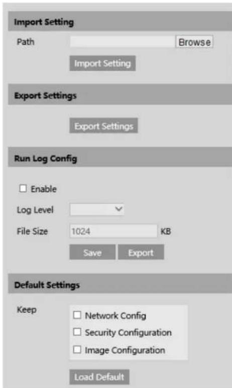
- Import & Export Settings
Configuration settings of the camera can be exported from a camera into another camera.
-
Click "Browse" to select the save path for import or export information on the PC.
-
Click the "Import Setting" or "Export Setting" button.
Note: The login password needs to be entered after clicking the "Import Setting" button.
- Running Log Settings
After enabling it, select the log level and file size and click "Save". Then the system will collect logs accordingly. When the device error occurs, you can export these logs and send them to the technician to find out the problem.
Log Level: it is recommended to select "INFO" or "Debug".
- Default Settings
Click the "Load Default" button and then verify the password to restore all system settings to the default factory settings except those you want to keep.
4.7.2 Reboot
Go to Maintenance→Reboot.
Click the "Reboot" button to reboot the device.
Timed Reboot Setting:
If necessary, the camera can be set up to reboot on a time interval. Enable "Time Settings", set the date and time and then click the "Save" button to save the settings.
4.7.3 Upgrade
Go to Maintenance→Upgrade. In this interface, the camera firmware can be updated.
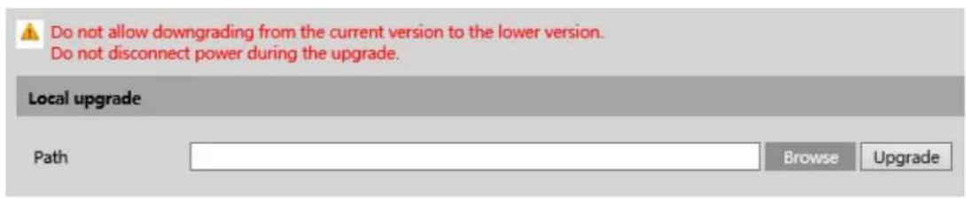
-
Click the "Browse" button to select the save path of the upgrade file
-
Click the "Upgrade" button to start upgrading the firmware.
-
The device will restart automatically
Caution! Do not close the browser or disconnect the camera from the network during the upgrade.
4.7.4 Operation Log
To query and export log:
- Go to Maintenance→Operation Log.
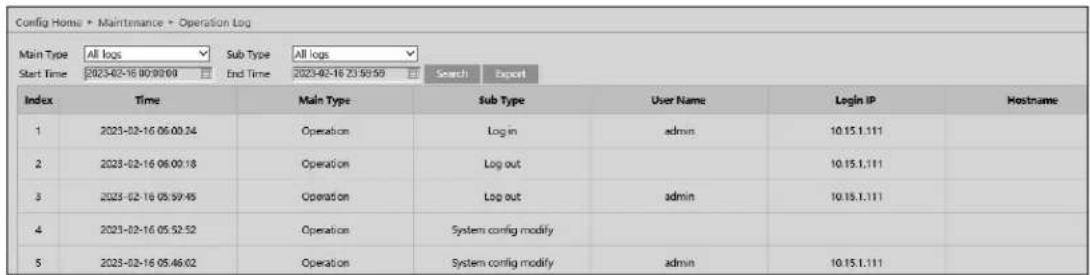
- Select the main type, sub type, start and end time.
- Click "Search" to view the operation log.
- Click "Export" to export the operation log.
5 Search
5.1 Image Search
In the Setup interface, click Search to go to the interface as shown below. Images that are saved on the PC or SD card can be found here.

- Local Image Search
- Choose "Picture"—"Local".
- Set time: Select date and choose the start and end time.
- Click to search the images.
- Double click a file name in the list to view the captured photos as shown above.
Click to return to the previous interface.
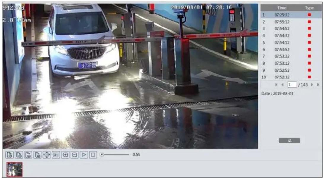
- SD Card Image Search
- Choose "Picture"—"SD Card".
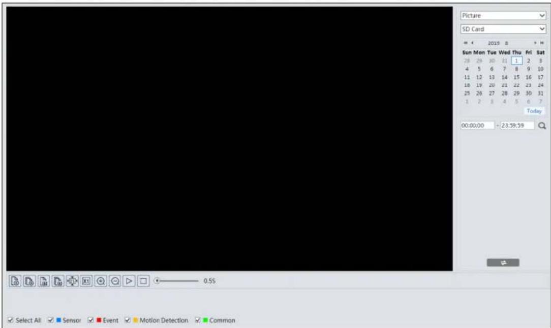
- Set time: Select date and choose the start and end time.
- Choose the alarm events at the bottom of the interface.
- Click to search the images.
- Double click a file name in the list to view the captured photos.
Click to return to the previous interface.
The descriptions of the buttons are shown as follows.
| Icon | Description | Icon | Description |
 | Close: Select an image and click this button to close the image. | [5T6D] | Close all: Click this button to close all images. |
 | Save: Click this button to select the path for saving the image on the PC. |  | Save all: Click this button to select the path for saving all pictures on the PC. |
| [T50Z] | Fit size: Click to fit the image on the screen. |  | Actual size: Click this button to display the actual size of the image. |
 | Zoom in: Click this button to digitally zoom in. |  | Zoom out: Click this button to digitally zoom out. |
| [0K5K] | Slide show play: Click this button to start the slide show mode. | [7X80] | Stop: Click this button to stop the slide show. |
 | Play speed: Play speed of the slide show. | ||
5.2 Video Search
5.2.1 Local Video Search
Click Search to go to the interface as shown below. Videos were recorded locally to the PC can be played in this interface.
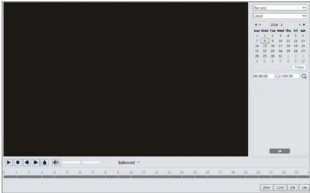
- Choose "Record"—"Local".
- Set search time: Select the date and choose the start and end time.
- Click to search the images.
- Double click on a file name in the list to start playback.
| Icon | Description | Icon | Description |
 | Play button. After pausing the video, click this button to continue playing. | Pause button | |
 | Stop button | Speed down | |
| [08CZ] | Speed up | Watermark display | |
  | Enable / disable audio; drag the slider to adjust the volume after enabling audio. | ||
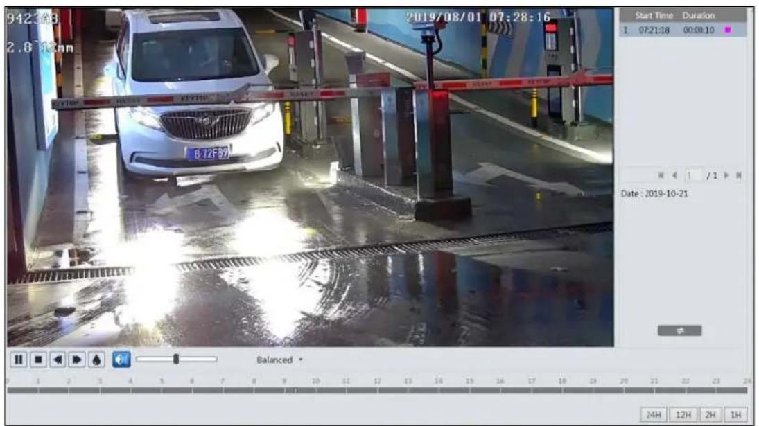
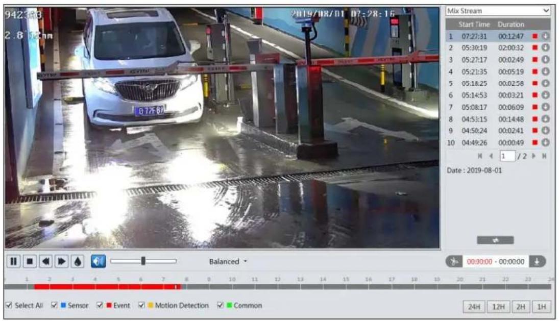
5.2.2 SD Card Video Search
Click Search to go to the interface as shown below. Videos that were recorded on the SD card can be played in this interface.
- Choose "Record"—"SD Card".
- Set search time: Select the date and choose the start and end time.
- Click to search the images.
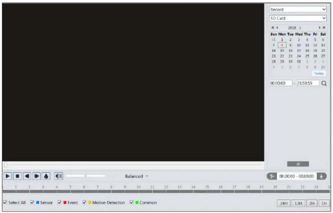
- Select the alarm events at the bottom of the interface.
- Select mix stream (video and audio stream) or video stream as needed.
- Double click on a file name in the list to start playback.
The time table can be shown in 24H/12H/2H/1H format by clicking the corresponding buttons.
Video clip and downloading
- Search the video files according to the above mentioned steps.
- Select the start time by clicking on the time table.
- Click to set the start time and then this button turns blue ( ).
- Select the end time by clicking on the time table. Then click 📋 to set the end time.
- Click to download the video file in the PC.

Click "Set up" to set the storage directory of the video files.
Click "Open" to play the video.
Click "Clear List" to clear the downloading list.
Click "Close" to close the downloading window.
5.3 Vehicle Data Search
Click "Data Record" to enter the vehicle log search interface.
Set the start time and end time and click "Search" to view the license plate recognition result.
You can also filter the plate number by selecting the list type or entering the desired license plate number.
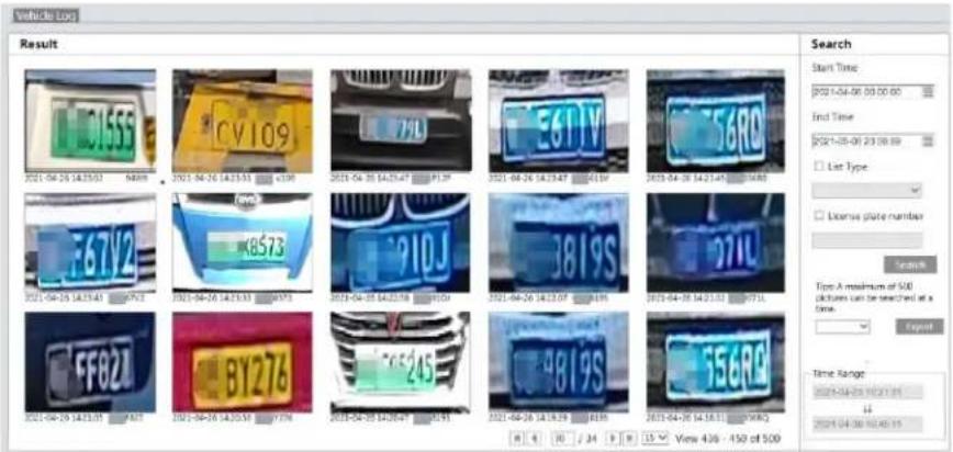
Please export image and file as needed. Click the searched license plate picture to view the original picture.
Appendix
Appendix 1 Troubleshooting
IP Scanner does not show any device.
Make sure that the PC that's running IP Scanner is on the same local network as the devices.
Internet Explorer cannot download ActiveX control.
IE browser may be set up to block ActiveX. Follow the steps below.
- Open IE browser and then click Tools→Internet Options.
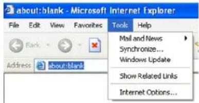
- Select Security→Custom Level.
- Enable all the options under "ActiveX controls and plug-ins".
- Click OK to finish setup.
No sound can be heard.
- Audio input device is not connected. Please connect and try again.
- Audio function is not enabled at the corresponding channel. Please enable this function.
Models: O2BLP1M/ O2BLP2M
Federal Communications Commission (FCC) Statements
This device complies with Part 15 of the FCC Rules. Operation is subject to the following two conditions: (1) This device may not cause harmful interference, and (2) This device must accept any interference received, including interference that may cause undesired operation.
FCC Responsible Party:
Speco Technologies
200 New Highway
Amityville, NY11701
www.specotech.com


- User Manual 2MP License Plate Recognition IP Camera
- Important Safeguards and Warnings
- Electrical safety
- Environment
- Operation and Daily Maintenance
- Warning
- Statement
- Regulatory Information
- FCC conditions:
- FCC compliance:
- Note:
- Table of Contents
- Search....39
- Appendix....45
- Appendix 1 Troubleshooting....45
- Introduction
- Welcome
- Main Features
- Applications
- Web Access and Login
- Live View
- Camera Configuration
- System Configuration
- System Information
- Date and Time
- Local Recording
- Storage
- - SD Card Management
- - Schedule Recording Settings
- Weekly schedule
- Day schedule
- - Snapshot Settings
- Video Configuration
- Image Configuration
- Backlight Compensation (BLC):
- Antiflicker:
- Video / Audio Configuration
- OSD Configuration
- Video Mask
- ROI Configuration
- Zoom/Focus
- Alarm Setup
- Motion Detection
- Other Alarms
- SD Card Full
- - SD Card Error
- IP Address Conflict
- - Cable Disconnection
- Alarm In (Sensor Input)
- Alarm Out
- Alarm Server
- Event Configuration
- Exception
- ※ The requirements of camera and surrounding area
- Automatic Number Plate Recognition (ANPR) Settings
- To set the detection area:
- To set the blocked area
- - Add vehicles
- - Search vehicles
- ※ Configuration requirements of camera and surrounding area
- Network Configuration
- TCP/IP
- Port
- Server Configuration
- DDNS
- SNMP
- 802.1x
- RTSP
- Multicast Address
- RTMP
- UPNP
- FTP
- HTTPS
- HTTP POST
- QoS
- Security Configuration
- User Admin
- Add user:
- Modify user:
- Delete user:
- Online User
- Block and Allow Lists
- Security Management
- - Password Security
- Maintenance Configuration
- Backup and Restore
- - Import & Export Settings
- - Running Log Settings
- - Default Settings
- Reboot
- Timed Reboot Setting:
- Upgrade
- Operation Log
- Search
- Image Search
- - Local Image Search
- - SD Card Image Search
- Video Search
- Local Video Search
- SD Card Video Search
- Vehicle Data Search
- Appendix
- Appendix 1 Troubleshooting
- No sound can be heard.
- Federal Communications Commission (FCC) Statements
- FCC Responsible Party:
Brand : Speco Technologies
Model : O2BLP2M
Category : Unspecified