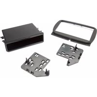
99-6544B - Audio Installation Kit Metra - Free user manual and instructions
Find the device manual for free 99-6544B Metra in PDF.


| Product Type | Car Audio Installation Kit |
| Brand | Metra |
| Model | 99-6544B |
| Compatibility | Select Ford, Lincoln, Mercury vehicles (2000-2010) |
| Color | Black |
| Material | High-grade ABS plastic |
| Dimensions (W x H x D) | 7.5 x 4.5 x 3.25 inches |
| Weight | 1.4 lbs (0.64 kg) |
| Mounting Depth | Up to 5 inches |
| Included Components | Dash kit, mounting brackets, screws, wiring harness adapter |
| Warranty | 1 year limited |
| Special Features | Factory-matched texture, snap-in installation, antenna adapter included |
| Power Input | 12V DC (vehicle battery) |
| Operating Temperature | -40°F to 185°F (-40°C to 85°C) |
| Certifications | CE, RoHS |
| Repair Parts Availability | Brackets and harnesses sold separately |
Frequently Asked Questions - 99-6544B Metra
User questions about 99-6544B Metra
0 question about this device. Answer the ones you know or ask your own.
Ask a new question about this device
Download the instructions for your Audio Installation Kit in PDF format for free! Find your manual 99-6544B - Metra and take your electronic device back in hand. On this page are published all the documents necessary for the use of your device. 99-6544B by Metra.
USER MANUAL 99-6544B Metra
natural_image
Close-up of a car air intake console with control knobs and vent gels (no visible text or symbols)Fiat 500 2016-up\*
*Visit MetraOnline.com for up-to-date vehicle specific applications.
KIT FEATURES
• ISO DIN radio provision with pocket
- Painted scratch resistant matte black
KIT COMPONENTS
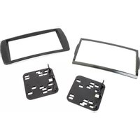
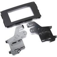
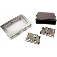
• A) Radio trim panel • B) Radio brackets • C) Pocket • D) (8) #8 x 3/8" Phillips screws
A

natural_image
Line drawing of a rectangular frame with a small protrusion and mounting bracket (no text or symbols)
natural_image
Two technical line drawings of metal bracket components with holes and internal features (no text or symbols)The image is too blurry to recognize any text content.

natural_image
Isometric line drawing of a rectangular electronic device with mounting brackets (no text or symbols)
TABLE OF CONTENTS
Dash Disassembly 2
Kit Preparation 3
Kit Assembly 3
WIRING & ANTENNA CONNECTIONS(sold separately)
Wiring Harness: Please visit metraonline.com for additional adapters and accessories.
Antenna Adapter: 40-EU55
TOOLS REQUIRED
- Panel removal tool • Phillips screwdriver
• T-25 Torx driver • Cutting tool
CAUTION! All accessories, switches, climate controls panels, and especially air bag indicator lights must be connected before cycling the ignition. Also, do not remove the factory radio with the key in the on position, or while the vehicle is running.
DASH DISASSEMBLY
- Unsnap and remove the climate control cover panel. (Figure A)
- Remove (2) T-25 Torx screws and unclip and remove the painted dash panel. (Figures B,C)

natural_image
Mechanical assembly diagram showing a gear and valve mechanism (no text or labels)(Figure A) (Figure D)
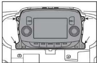
- Remove (4) T-25 Torx from the radio trim panel including vents and remove the panel. (Figures D, E))
- Remove (4) T-25 Torx to remove the radio (Figure F)
Continue to Kit Preparation

natural_image
Technical line drawing of a car dashboard frame with control buttons and mounting points (no text or symbols)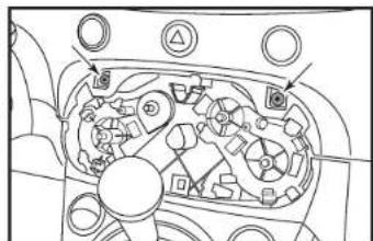
natural_image
Technical diagram of a mechanical assembly with no visible text or symbols(Figure B) (Figure E)

natural_image
Diagram of a car intake manifold showing internal components and directional arrows (no text or labels)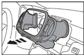
natural_image
Diagram of a car intake manifold showing internal components and directional arrows (no text or labels)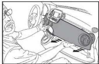
natural_image
Person working on a car interior with steering wheel and dashboard (no visible text or symbols)(Figure C) (Figure F)
natural_image
Top-down schematic of a vehicle dashboard with control panels and buttons (no text or symbols)KIT PREPARATION
KIT ASSEMBLY
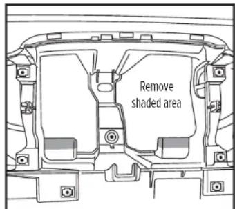
- Cut and remove the shaded area from the sub-dash to allow clearance for the aftermarket radio. (Figure A)
Continue to Kit Assembly
(Figure A)
ISO-DIN radio provision with pocket
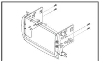
- Attach thedio brackets to the radio trim panel using (4) #8 x 3/8" Phillips screws supplied. (Figure A)
- Attach the pocket to the bracket assembly using the (4) supplied #8 x 3/8" Phillips screws. (Figure B)
- Remove the metal DIN sleeve and trim ring from the aftermarket radio.
- Slide the radio into the completed assembly, and then secure it to the assembly using screws supplied with the radio. (Figure C)
- Locate the factory wiring harness and antenna connector in the dash, and complete all necessary connections to the radio. Metra recommends using the proper mating adapter from Metra and/or AXXESS. Test the radio for proper operation.
- Reassemble the dash in reverse order of disassembly.
(Figure A)

natural_image
Technical line drawing of a vehicle front panel assembly (no text or symbols)(Figure B)

(Figure C)
IMPORTANT
If you are having difficulties with the installation of this product, please call our Tech Support line at 1-800-253-TECH. Before doing so, look over the instructions a second time, and make sure the installation was performed exactly as the instructions are stated. Please have the vehicle apart and ready to perform troubleshooting steps before calling.

KNOWLEDGE IS POWER
Enhance your installation and fabrication skills by enrolling in the most recognized and respected mobile electronics school in our industry.
Log onto www.installenstitute.com or call 800-354-6782 for more information and take steps toward a better tomorrow.

Metra recommends MECP certified technicians


Brand : Metra
Model : 99-6544B
Category : Audio Installation Kit