ZES3921IBA - Cooker ZANUSSI - Free user manual and instructions
Find the device manual for free ZES3921IBA ZANUSSI in PDF.

User questions about ZES3921IBA ZANUSSI
0 question about this device. Answer the ones you know or ask your own.
Ask a new question about this device
Download the instructions for your Cooker in PDF format for free! Find your manual ZES3921IBA - ZANUSSI and take your electronic device back in hand. On this page are published all the documents necessary for the use of your device. ZES3921IBA by ZANUSSI.
USER MANUAL ZES3921IBA ZANUSSI
text_image
R 5mm 600mm 490+1mm 270+1mm
text_image
Technical diagram showing a structural assembly with downward force arrows and a magnified view of a beam support.Bagside Maks. 180 mm
text_image
R 5mm 600mm 490+1mm 270+1mm
text_image
Diagram illustrating a structural load application on a layered material, showing downward force and circular load distribution.| Safety information | 17 |
| Installation | 18 |
| Product description | 20 |
| Operation | 20 |
| Helpful hints and tips | 21 |
| Care and cleaning | 21 |
| What to do if... | 22 |
| Technical data | 23 |
| Environment concerns | 23 |
Subject to change without notice.

Safety information
For your safety and correct operation of the appliance, read this manual carefully before installation and use. Always keep these instructions with the appliance even if you move or sell it. Users must fully know the operation and safety features of the appliance.
General safety
Warning! Persons (including children) with reduced physical sensory, mental capabilities or lack of experience and knowledge must not use the appliance. They must have supervision or instruction for the operation of the appliance by a person responsible for their safety.

The appliance is not intended to be operated with external timer or separated remote-control system.
Child safety
- Only adults can use this appliance. Children must get supervision to make sure that they do not play with the appliance.
- Keep all packaging away from children. There is a risk of suffocation and physical injury.
- Keep children away from the appliance during and after the operation, until the appliance is cold.
Safety during operation
- Remove all packaging, stickers and layers from the appliance before the first use.
- Set the cooking zones to "off" after each use.
- Risk of burns! Do not put cutlery or saucepan lids on the cooking surface, as they can become hot.

Warning! Fire danger! Overheated fats and oils can ignite very quickly.
Correct operation
• Always monitor the appliance during operation.
- Only use the appliance for domestic cooking tasks!
- Do not use the appliance as a work or a storage surface.
- Do not put or keep very flammable liquids and materials, or fusible objects (made of plastic or aluminium) on or near the appliance.
- Be careful when you connect the appliance to the near sockets. Do not let electricity bonds touch the appliance or hot cookware. Do not let electricity bonds tangle.
How to prevent a damage to the appliance
- If the objects or cookware fall on the glass ceramic, the surface can be damaged.
- Cookware made of cast iron, cast aluminium or with damaged bottoms can scratch the glass ceramic if you move them on the surface.
- Do not let cookware boil dry to prevent the damage to cookware and glass ceramics.
- Do not use the cooking zones with empty cookware or without cookware.
- Do not cover any part of the appliance with aluminium foil.
- If there is a crack on the surface, disconnect power supply to prevent the electric shock.
Disposal of the appliance
- To prevent the risk of physical injury or damage
- Disconnect the appliance from the power supply.
- Cut off the mains cable where it connects with the appliance and discard it.
- Speak to your local authorised facilities for disposal of your appliance.
Installation

Warning! Read and follow the instructions carefully. There is a risk of injury or damage to the appliance.
- Make sure that the appliance is not damaged because of transportation. Do not connect a damaged appliance. If it is necessary, speak to the supplier.
- Installation and connection of the appliance to the power supply must only be done by qualified personnel.
- Only use built-in appliances after you assemble the appliance into correct built-in units and work surfaces that obey the standards.
- Do not change the specifications or modify this product. There is a risk of injury or damage to the appliance.
- Fully obey the laws, ordinances, directives and standards in force in the country where you use the appliance (safety regulations, recycling regulations, electrical safety rules etc.).
- Keep the minimum distances to other appliances and units.
- Install anti-shock protection, for example install the drawers only with a protective panel directly below the appliance.
- If the fixing bracket is near to the terminal block, always make sure the connection cable does not come in contact with the edge of the bracket.
- Prevent damage of the cut surfaces of the worktop against moisture with a correct sealant!
- Seal the appliance to the worktop with no space left with a correct sealant.
- Prevent damage of the bottom of the appliance from steam and moisture, e.g. from a dishwasher or oven.
- Do not install the appliance adjacent to doors and below windows. Hot cookware can be hit off the hob when you open doors or windows.
- Disconnect the appliance from the electrical supply, before you do maintenance work or cleaning.

Warning! Risk of injury from electrical current.
Carefully obey the instructions for electrical connections.
- The electrical mains terminal is live.
- Make the electrical mains terminal free of voltage.
• Install correctly to give anti-shock protection. - Loose and incorrect mains plug and socket connections can make the terminal become too hot.
- A qualified electrician must install the clamping connections correctly.
- Use a strain relief clamp on cable.
- Use the correct mains connection cable and replace the damaged mains cable with the proper cable type. Speak to your local Service Centre.
The appliance must have the electrical installation which lets you disconnect the appliance from the mains at all poles with a contact opening width of minimum 3 mm.
You must have correct isolation devices: line protecting cut-outs, fuses (screw type fuses removed from the holder), ground leakage trips and contactors.
The manufacturer is not responsible for any injury to persons and pets or damage to property caused by failure to obey these requirements.
Electrical connection
- Ground the appliance according to safety precautions.
- Make sure that the rated voltage and type of power on the rating plate agree with the voltage and the power of the local power supply.
- This appliance is supplied with a mains cable. It has to be supplied with a correct plug, able to support the load marked on the rating plate. The plug has to be fitted in a correct socket.
- Any electrical component must be installed or replaced by the Service Force Centre technician or qualified service personnel.
- Always use a correctly installed shockproof socket.
- Make sure that there is an access to the mains plug after installation.
- Do not pull the mains cable to disconnect the appliance. Always pull the mains plug.
- The appliance must not be connected with an extension cable, an adapter or a multiple connection (risk of fire). Check that the ground connection is in conformity with the standard and regulations force.
-
The power cable must be placed in such a way that it does not touch any hot part.
-
Connect the appliance to the mains with a device that lets to disconnect the appliance from the mains at all poles with a contact opening width of minimum 3 mm, eg. automatic line protecting cut-out, earth leakage trips or fuse.
- None of a parts of the connection cable can not get a temperature 90 °C. The blue neutral cable must be connected to the terminal block label with "N". The brown (or black) phase cable (fitted in the terminal block contact marked with "L") must always be connected to the live phase.
Replacement of the connection cable
To replace the connection cable use only H05V2V2-F T90 or equivalent type. Make sure that the cable section is applicable to the voltage and the working temperature. The yellow/green earth wire must be approximately 2 cm longer than the brown (or black) phase wire.
Assembly
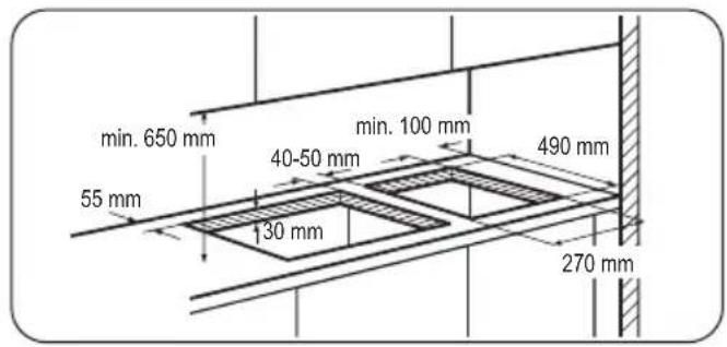
text_image
min. 650 mm 55 mm 40-50 mm 130 mm min. 100 mm 490 mm 270 mmIf several 30 cm hobs are to be installed side by side into the same cut out, an assembly kit including a support side bracket and supplementary seals is available at our Service Centres. The relevant installation instructions are supplied within the kit package.
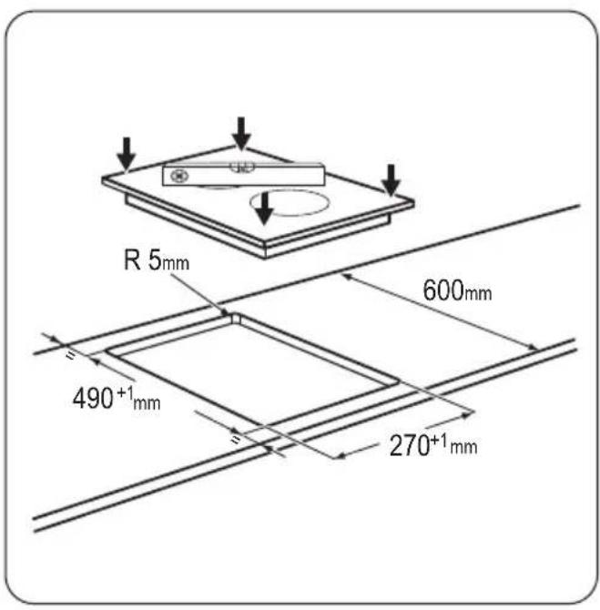
text_image
R 5mm 600mm 490+1mm 270+1mm
text_image
Diagram illustrating a structural load application on a plate with circular holes, showing force direction and component placement.Possibilities for insertion
Kitchen unit with door
The panel installed below the hob must be easy to remove and let an easy access in case a technical assistance intervention is necessary.

text_image
130 mm min 20 mm (max 150 mm) 60 mm a ba) Removable panel
b) Space for connections
Kitchen unit with oven
The hob recess dimensions must obey the indication and the kitchen unit must be equipped with vents to let a con-
Product description
Cooking surface layout

text_image
180 mm 145 mm 1 2 3 4Electric cooking zones control knobs
Symbol Function
0 off position
Operation
To switch on and increase the heat setting turn the knob counterclockwise. To decrease the heat setting turn the knob clockwise. To switch off turn the knob to the 0. Power indicator is activated when either of the zones are turned on, and will stay on until the cooking zones are switched off.
Before first use
Put cookware containing water on each cooking zone, set the maximum position and operate the appliance for 10
tinuous supply of air. The electrical connection of the hob and the oven must be installed separately for safety reasons and to let easy remove oven from the unit.

text_image
50 cm² 360 cm² 120 cm² 180 cm²1 Rear cooking zone 1700 W
2 Front cooking zone 1200 W
3 Power indicator
4 Control knobs
| Symbol Function |
| 1 minimum heat |
| 6 maximum heat |
min. This is to burn off the residue in the appliance. After that, operate the appliance at minimum position for 20 min. During this period, an odour and smoke can occur. This is normal. Make sure that the airflow is sufficient.
When a cooking zone operates, it hums for a short time. This is typical of all ceramic glass cooking zones and does not show that the appliance operates incorrectly.
Cookware

- The bottom of the cookware must be as thick and flat as possible.
- Cookware made of enamelled steel and with aluminium or copper bottoms can cause discoloration on glass ceramic surface.
Energy saving

- If possible, always put the lids on the cookware.
- Put cookware on a cooking zone before you start it.
- Stop the cooking zones before the end of the cooking time to use residual heat.
- The bottom of pans and cooking zones must have the same dimension.

Use pots and pans with bottom applicable to the dimension of the cooking zones.
Cooking zone Diameters of cookware
Front max. 145 mm
Cooking zone Diameters of cookware
Rear max. 180 mm
Examples of cooking applications
| Heat setting: | Use to: |
| 1 Keeping warm | |
| 2 Gentle simmering | |
| 3 Simmering | |
| 4 Frying / browning | |
| 5 Bringing to the boil | |
| 6 Bringing to the boil / quick frying / deep-frying | |
Information on acrylamides
Important! According to the newest scientific knowledge, if you brown food (specially the one which contains starch), acrylamides can pose a health risk. Thus, we recommend that you cook at the lowest temperatures and do not brown food too much.
Care and cleaning
Clean the appliance after each use.
Always use cookware with clean bottom.

Warning! Before any maintenance or cleaning can be carried out, you must disconnect the hob from electricity supply.

The hob is best cleaned while it is still warm, as a spillage can be removed more easily than if it is left vol.

Warning! Sharp objects and abrasive cleaning agents will damage the appliance.
For your safety, do not clean the appliance with steam blasters or high-pressure cleaners.

Scratches or dark stains on the glass ceramic have no effect on how the appliance operates.
To remove the dirt:
- – Remove immediately: melted plastic, plastic foil, and food with sugar. If not, the dirt can cause damage to the appliance. Use a special scraper for the glass. Put the scraper on the glass surface at an acute angle and move the blade on the surface.
-
Remove after the appliance is sufficiently cool:limescale rings, water rings, fat stains, shiny metallic discolorations. Use a special cleaning agent for glass ceramic or stainless steel.
-
Clean the appliance with a moist cloth and some detergent.
- At the end rub the appliance dry with a clean cloth.
| Problem Possible cause and remedy | |
| The appliance does not operate. • Examine the fuse in the electrical system of the house in the fuse box. If the fuses blow time after time, speak to an authorised electrician. | |
| The cooking zone does not heat up. | • Make sure that the appliance is plugged in and the electrical supply is switched on.• Make sure that you turn the correct control knob.• Examine the fuse in the electrical system of the house in the fuse box. If the fuses blow time after time, speak to an authorised electrician. |
| The effectiveness of the hob is not satisfactory. | • Make sure that the hob is clean and dry.• Make sure that the cookware is the correct size for the cooking zone.• Make sure that the cookware has a flat bottom.• Make sure that the heat setting is correct for this type of cooking. |
If there is a fault, first try to find a solution to the problem yourself. If you cannot find a solution to the problem yourself, speak your dealer or the local Service Force Centre.

If you operated the appliance incorrectly, or the installation was not carried out by a registered engi-
neer, the visit from the customer service technician or dealer may not take place free of charge, even during the warranty period.
Labels supplied with the accessories bag
Stick the adhesive labels as indicated below:

flowchart
graph TD
    A["MOD. PROD.NO. SER.NO DATA"] --> B["MODELNODEL"]
    C["MOD. PROD.NO. SER.NO DATA"] --> B
    D["03 IT MADE IN ITALY"] --> E["TYPE 230V-50Hz IP20"]
    B --> F["Measurement Icon"]
    style A fill:#f9f,stroke:#333
    style C fill:#f9f,stroke:#333
    style D fill:#ccf,stroke:#333
    style B fill:#cfc,stroke:#333
    style E fill:#fcc,stroke:#333
1 Stick it on Guarantee Card and send this part
2 Stick it on Guarantee Card and keep this part
3 Stick it on instruction booklet
These data are necessary to help you quickly and correctly. These data are available on the supplied rating plate.
- Model description ....
- Product number (PNC) ....
- Serial Number (S.N.) ....
Use the original spare parts only. They are available at Service Force Centre and approved spare parts shops.
Technical data
Hob dimensions
| Width: 290 mm | |
| Length: 510 mm |
Hob recess dimensions
| Width: 270 mm | |
| Length: 490 mm |
Environment concerns
The symbol on the product or on its packaging indicates that this product may not be treated as household waste. Instead it should be taken to the appropriate collection point for the recycling of electrical and electronic equipment. By ensuring this product is disposed of correctly, you will help prevent potential negative consequences for the environment and human health, which could otherwise be caused by inappropriate waste handling of this product. For more detailed
Hot plate rating
| Rear cooking zone 180 mm | 1.7 kW |
| Front cooking zone 145 mm | 1.2 kW |
| Total rating 2.9 kW | |
| Electric supply 230 V ~ 50 Hz |
information about recycling of this product, please contact your local council, your household waste disposal service or the shop where you purchased the product.
Packaging material
The packaging materials are friendly to the environment and can be recycled. The plastic components are identified by marking: >PE<,>PS<, etc. Discard the packaging materials as household waste at the waste disposal facilities in your municipality.
Sommaire
text_image
R 5mm 600mm 490+1mm 270+1mm
text_image
Diagram illustrating a structural load application on a plate with circular holes, showing force direction and component placement.text_image
R 5mm 600mm 490+1mm 270+1mm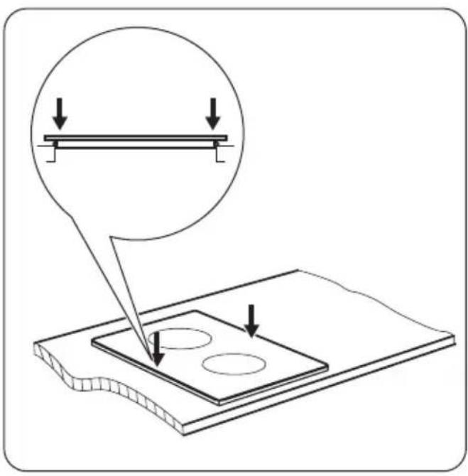
text_image
Diagram illustrating a structural load application on a plate with circular holes, showing force direction and component placement.Einbaumöglichkeiten
www.zanussi.com/shop