Simple 2263 - Sewing machine SINGER - Free user manual and instructions
Find the device manual for free Simple 2263 SINGER in PDF.

User questions about Simple 2263 SINGER
0 question about this device. Answer the ones you know or ask your own.
Ask a new question about this device
Download the instructions for your Sewing machine in PDF format for free! Find your manual Simple 2263 - SINGER and take your electronic device back in hand. On this page are published all the documents necessary for the use of your device. Simple 2263 by SINGER.
USER MANUAL Simple 2263 SINGER
natural_image
Line drawing of a sewing machine with no text or symbolsINSTRUCTION MANUAL
2263
SINGER is sewing made easy.™
Welcome to the SINGER® family and CONGRATULATIONS on purchasing a brand new SINGER® sewing machine!
The SINGER® brand has stood for quality in sewing for over 160 years. We design our machines for sewists of all skill levels so that the joy of sewing, creating, do-it-yourself, crafting and more can be enjoyed by all. It is important to us that you have the easiest and most successful sewing experience, so we have provided a wide array of helpful resources:
- An instruction manual with easy-to-understand graphics and step-by-step instructions.
- Assistance on the web at www.singerco.com.
- Personal assistance via email: talktous@singerco.com.
- Live, one-on-one help from one of our SINGER® Sewing Assistants, at 1-844-664-5188 (North America Only).
We're ready to help and hope that you enjoy your SINGER® sewing machine.
Happy Sewing!
This household sewing machine is designed to comply with IEC/EN 60335-2-28 and UL1594.
IMPORTANT SAFETY INSTRUCTIONS
When using an electrical appliance, basic safety precautions should always be followed, including the following:
Read all instructions before using this household sewing machine. Keep the instructions in a suitable place close to the machine. Make sure to hand them over if the machine is given to a third party.
DANGER - To reduce the risk of electric shock :
- A sewing machine should never be left unattended when plugged in. Always unplug this sewing machine from the electric outlet immediately after using and before cleaning, removing covers, lubricating or when making any other user servicing adjustments mentioned in the instruction manual.
WARNING - To reduce the risk of burns, fire, electric shock, or injury to person :
- Do not allow to be used as a toy. Close attention is necessary when this sewing machine is used by or near children.
- Use this sewing machine only for its intended use as described in this manual. Use only attachments recommended by the manufacturer as contained in this manual.
- Never operate this sewing machine if it has a damaged cord or plug, if it is not working properly, if it has been dropped or damaged, or dropped into water. Return the sewing machine to the nearest authorized dealer or service center for examination, repair, electrical or mechanical adjustment.
- Never operate the sewing machine with any air openings blocked. Keep ventilation openings of the sewing machine and foot control free from the accumulation of lint, dust, and loose cloth.
- Keep fingers away from all moving parts. Special care is required around the sewing machine needle.
- Always use the proper needle plate. The wrong plate can cause the needle to break.
- Do not use bent needles.
- Do not pull or push fabric while stitching. It may deflect the needle causing it to break.
- Wear safety glasses.
- Switch the sewing machine off ("O") when making any adjustment in the needle area, such as threading needle, changing needle, threading bobbin, or changing presser foot, etc.
- Never drop or insert any object into any opening.
- Do not use outdoors.
- Do not operate where aerosol (spray) products are being used or where oxygen is being administrated.
INTRODUCTION
Important Safety Instructions
- To disconnect, turn all controls to the off ("O") position, then remove plug from outlet.
- Do not unplug by pulling on cord. To unplug, grasp the plug, not the cord.
- The foot control is used to operate the machine. Avoid placing other objects on the foot control.
- Do not use the machine if it is wet.
- If the LED lamp is damaged or broken, it must be replaced by the manufacturer or its service agent or a similarly qualified person, in order to avoid a hazard.
- If the supply cord connected with the foot control is damaged, it must be replaced by the manufacturer or its service agent or a similarly qualified person, in order to avoid a hazard.
- This sewing machine is provided with double insulation. Use only identical replacement parts. See instructions for Servicing of Double-Insulated Appliances.
SAVE THESE INSTRUCTIONS
For Europe only :
This appliance can be used by children aged from 8 years and above and persons with reduced physical, sensory or mental capabilities or lack of experience and knowledge if they have been given supervision or instruction concerning use of the appliance in a safe way and understand the hazards involved. Children shall not play with the appliance. Cleaning and user maintenance shall not be made by children without supervision. The noise level under normal operating conditions is less than 75dB(A). The machine must only be used with foot control of type KD-1902, FC-1902 (110-120V area) / KD-2902, FC-2902A, FC-2902C, FC-2902D (220-240V area) manufactured by ZHEJIANG FOUNDER MOTOR CORPORATION LTD. (China) / 4C-316B (110-125V area) / 4C-316C (127V area) / 4C-326C (220V area) / 4C-326G (230V area) / 4C-336G (240V area) / 4C-336G (220-240V area) manufactured by Wakaho Electric Ind. Co., Ltd. (Vietnam)
For outside Europe :
This sewing machine is not intended for use by persons (including children) with reduced physical, sensory or mental capabilities, or lack of experience and knowledge, unless they have been given supervision or instruction concerning use of the sewing machine by a person responsible for their safety. Children should be supervised to ensure that they do not play with the sewing machine. The noise level under normal operating conditions is less than 75dB(A). The machine must only be used with foot control of type KD-1902, FC-1902 (110-120V area) / KD-2902, FC-2902A, FC-2902C, FC-2902D (220-240V area) manufactured by ZHEJIANG FOUNDER MOTOR CORPORATION LTD. (China) / 4C-316B (110-125V area) / 4C-316C (127V area) / 4C-326C (220V area) / 4C-326G (230V area) / 4C-336G (240V area) / 4C-336G (220-240V area) manufactured by Wakaho Electric Ind. Co., Ltd. (Vietnam)
SERVICING OF DOUBLE INSULATED PRODUCTS
In a double-insulated product, two systems of insulation are provided instead of grounding. No ground means is provided on a double-insulated product, nor should a means for grounding be added to the product. Servicing of a double-insulated product requires extreme care and knowledge of the system and should be done only by qualified service personnel. Replacement parts for a double-insulated product must be identical to those parts in the product. A double-insulated product is marked with the words “DOUBLE INSULATION” or “DOUBLE INSULATED”.
INTRODUCTION
Table of Contents
PREFACE....2
Welcome....2
Important Safety Instructions....3-
Table of Contents....6
SECTION ONE - ABOUT YOUR MACHINE......
Machine Parts Reference 7-8
Needle and Presser Foot Area Reference....
Removable Storage Compartment and Accessories ....
SECTION TWO - GETTING READY TO SEW....1
Powering Your Machine....11
Winding the Bobbin 12
Inserting the Bobbin....13
Threading the Upper Thread 14
Automatic Needle Threader....15
Drawing Up the Bobbin Thread 16
SECTION THREE - START SEWING....17
Before You Start Sewing 17
Stitch Formation....18
Stitch Selector Dial....19
Sewing a Straight Stitch....20
Sewing a Decorative Stitch 21
Sewing a Stretch Stitch 22
Sewing a 4-Step Buttonhole 23
Sewing a Button....24
Inserting and Changing Needles....2
Changing the Presser Foot 26
SECTION FOUR - TROUBLESHOOTING & MAINTENANCE ......
Troubleshooting 27-31
Maintenance 32
APPENDIX - GLOSSARY 33
Glossary of Key Sewing Terms 33
Explanation key to notations in this manual:

= Helpful information

= Could cause harm

= Impacts sewing results
To ensure that you are always provided with the most modern sewing capabilities, the manufacturer reserves the right to change
appearance, design or accessories of this sewing machine when considered necessary.
SINGER® is a registered trademark of The SINGER® Company Limited or its affiliates.
© 2016 The SINGER® Company Limited or its affiliates. All rights reserved.
ABOUT YOUR MACHINE
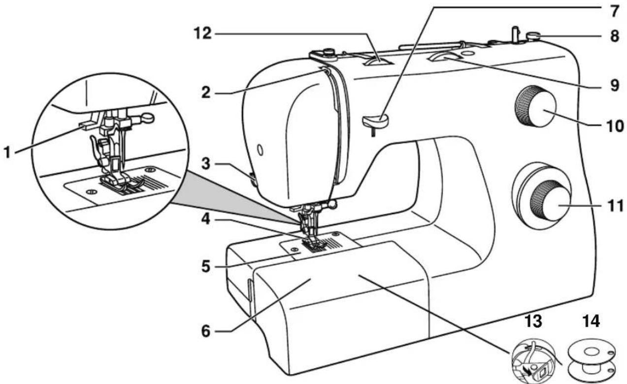
Main Parts of the Machine Front
1
text_image
Technical diagram of a sewing machine with numbered parts and an inset close-up of the component's base.-
NEEDLE THREADER LEVER is used to engage the automatic needle threader. (See Page 15)
-
THREAD TAKE-UP LEVER controls the flow of the upper thread while sewing. (See Page 14)
-
THREAD CUTTER is conveniently located for trimming thread ends at the end of sewing.
-
PRESSER FOOT holds fabric against feed teeth, drawing fabric under the foot for you as you sew. (See Page 26)
-
NEEDLE PLATE has guidelines to help you keep seams straight. (See Page 9)
-
REMOVABLE STORAGE COMPARTMENT provides flat surface for sewing, storage for accessories, and provides access to the free arm. (See Page 10)
-
REVERSE SEWING LEVER reverses stitching direction, for example, when securing the beginning and ending of a seam. (See Page 20)
-
BOBBIN WINDING STOPPER determines when bobbin is full and disengages automatically. (See Page 12)
-
STITCH WIDTH DIAL controls the width of stitches, making them narrower or wider. (See Page 19)
-
STITCH LENGTH DIAL controls the length of stitches, making them shorter or longer as desired. It is also used for stretch stitch length selection. (See Page 19)
-
STITCH SELECTOR DIAL is used to select stitch patterns and buttonhole settings. (See Page 19)
-
THREAD TENSION DIAL allows you to select just the right tension for your stitch, thread and fabric. (See Page 18)
-
BOBBIN CASE holds the bobbin in the bobbin holder. The bobbin case is located behind the hinged cover, accessible after taking off the removable storage compartment. (See Page 13)
-
BOBBIN holds the thread that forms the stitching that appears on the bottom side of the fabric. (See Page 12)
1
ABOUT YOUR MACHINE
Main Parts of the Machine Back

text_image
Labeled diagram of a sewing machine with numbered parts and an inset showing internal components-
HORIZONTAL SPOOL PIN holds the thread spool and spool cap for the upper thread.
-
BOBBIN WINDING SPINDLE holds bobbin as it winds. (See Page 12)
-
HOLE FOR SECOND SPOOL PIN is used to hold an additional spool pin (optional), for thread spools to be used in upright position or for using two spools at once for twin needle sewing.
-
HANDWHEEL (ALWAYS TURN IT TOWARD YOU), controls movement of the needle and the thread take-up lever.
-
POWER AND LIGHT SWITCH turns on machine and sewing light simultaneously. (See Page 11)
-
MAIN PLUG SOCKET is used to connect the power cord/foot control. (See Page 11)
-
BOBBIN WINDING TENSION DISK holds the thread snuggly to help ensure smooth and even bobbin winding. (See Page 12)
-
UPPER THREAD GUIDE helps maintain the flow of the thread during bobbin winding and sewing. (See Pages 12 and 14)
-
FACE PLATE houses and protects the interior mechanisms of the machine.
-
HANDLE is used for lifting and transporting the machine.
-
PRESSER FOOT LIFTER raises and lowers presser foot. It should be placed up for machine threading and down for sewing. (See Page 14)
-
FOOT CONTROL controls sewing speed by the amount of pressure applied by user. (See Page 11)
-
POWER CORD connects the machine to the power source. (See Page 11)
ABOUT YOUR MACHINE
Needle and Presser Foot Area
1

text_image
1 2 3 4 5 6 7 8 9 10 11 12 13 14-
NEEDLE THREADER LEVER is used to engage the automatic needle threader mechanism.
-
NEEDLE THREADER GUIDE holds thread securely before placing it in hook pin.
-
THREAD GUIDE controls movement of upper thread.
-
NEEDLE holds thread during stitch formation.
-
PRESSER FOOT SCREW secures the presser foot holder (shank) onto the presser bar.
-
PRESSER FOOT holds fabric against the feed dogs while sewing. Various optional presser feet are available, depending on fabric sewn and sewing techniques (see page 10).
-
FEED DOGS (OR FEED TEETH), which look like rows of teeth under the presser foot, control the movement of the fabric under the presser foot.
-
NEEDLE CLAMP holds the machine's needle in position.
-
NEEDLE CLAMP SCREW secures the needle when placed in needle clamp.
-
PRESSER FOOT RELEASE LEVER releases presser foot from the holder (shank) when changing feet.
-
PRESSER BAR accommodates the presser foot holder.
-
PRESSER FOOT HOLDER (OR SHANK) holds presser foot.
-
NEEDLE PLATE covers the bobbin area and provides flat area around presser foot for sewing.
-
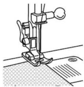
STITCHING GUIDELINES are used as a visual reference for guiding fabric straight while sewing. The first line is 3/8" (10mm) from center needle position. The most popular seam allowance measurements are 1/2" (13mm) and 5/8" (16mm). The 1/2" seam allowance is the 2nd line, and the 5/8" seam allowance is the 3rd line.
1
ABOUT YOUR MACHINE
Removable Storage Compartment and Accessories
natural_image
Line drawing of a hand operating a sewing machine with a sewing machine needle inserted (no text or symbols)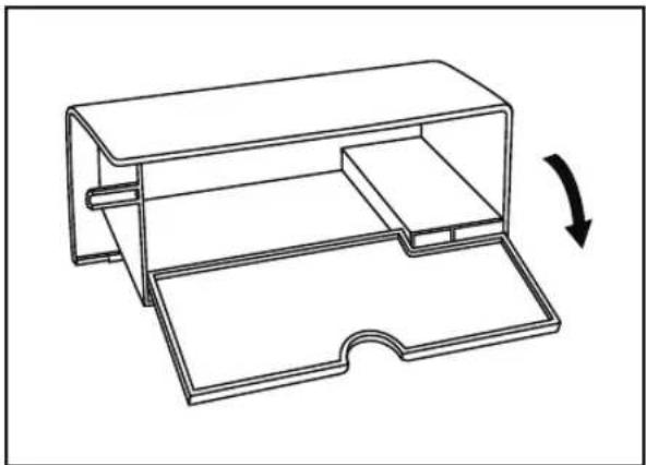
natural_image
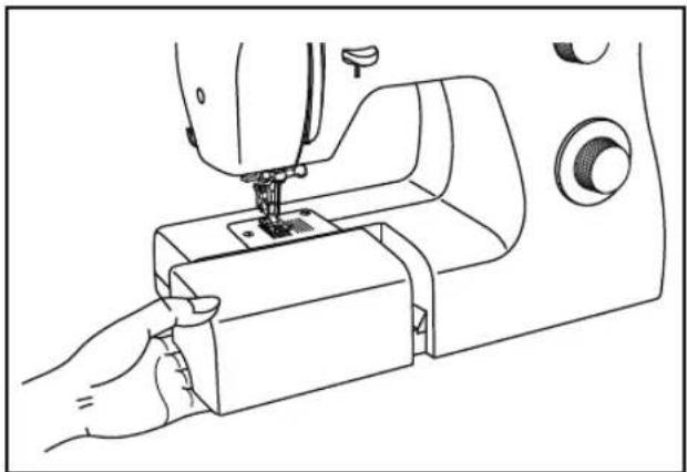
Technical line drawing of a mechanical housing or enclosure with an arrow indicating rotation (no text or symbols present)Hold the Removable Storage Compartment horizontally, then pull toward the left to remove it from the machine. Doing this, you will have access to the free arm, which makes it easy to sew tubular projects like pant hems or sleeves. Additionally, you will find the machine's accessories stored here (see below).
To replace the Removable Storage Compartment, hold it as shown in the illustration, and then push it to the right.
This machine comes with a standard assortment of presser feet and accessories.
Standard Accessories Included:
a. All Purpose Foot (for general sewing)
b. Button Sewing Foot (for attaching buttons)
c. Buttonhole Foot (for making buttonholes)
d. L-Screwdriver (to remove needle plate for cleaning)
e. Seam Ripper/Brush (remove stitches/brush out lint)
f. Pack of Needles (replacement needles)
g. Bobbins (SINGER® Class 15 transparent bobbins)
h. Darning Plate (cover for feed dogs)
i. Spool Holders (2 sizes for various thread spool styles)

text_image
a b c d e f g h iOptional Accessories:
For information about additional presser feet, attachments and accessories that may be available for your machine, visit www.singerco.com.
GETTING READY TO SEW
Powering Your Machine
2
text_image
Diagram showing connection between a device labeled 'A' and an electrical outlet with a switch, connected to a panel with an outlet panel.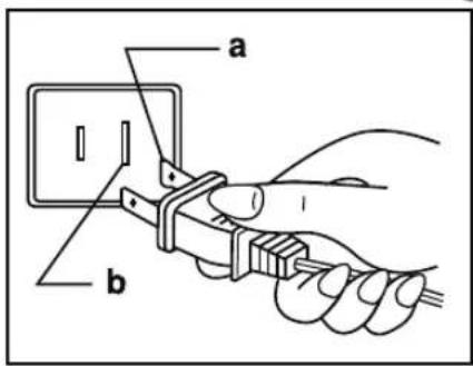
text_image
a b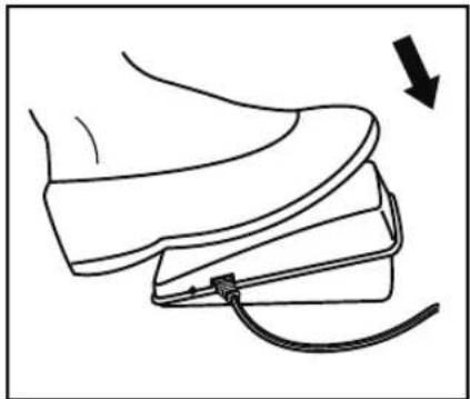
natural_image
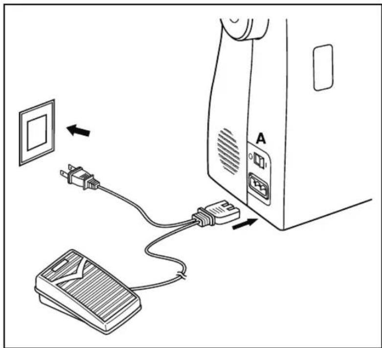
Line drawing of a shoe being held with a cable, showing a curved object and an arrow indicating motion (no text or symbols)Connect the machine to a power source as illustrated. This machine is equipped with a polarized plug which must be used with the appropriate polarized outlet. (a and b)

Unplug power cord when machine is not in use.
Foot Control
The foot control regulates the sewing speed. When foot control is disconnected, the machine will not operate.
Sewing Light
Press main switch (A) to "I" for power and light.
⚠ For machine with a polarized plug (one blade is wider than the other). To reduce the risk of electric shock, this plug is intended to fit in a polarized outlet only one way. If it does not fit fully in the outlet, reverse the plug. If it still does not fit, contact a qualified electrician to install the proper outlet. Do not modify the plug in any way.
2
GETTING READY TO SEW
Winding the Bobbin
→ This machine uses SINGER® Class 15 transparent bobbins.
Use only this style of bobbin when purchasing additional bobbins for your machine. Do not substitute with metal bobbins.

natural_image
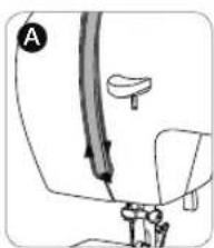
Illustration of a hand using a tool to lift a cylindrical component (no text or symbols present)- Place thread spool and corresponding size spool holder onto spool pin. Spool holder should be large enough to cover the end of the thread spool so thread unreels smoothly. For smaller, narrower spools, use the small spool cap, which can be found in the removable storage compartment.

text_image
Technical diagram of a mechanical device with labeled components A, B, and C, showing internal components and directional arrows.- (A) Snap thread into guide at top of machine. (B) Place thread snuggly around bobbin winding tension disk to ensure that thread winds onto bobbin smoothly and consistently. (C) Thread bobbin as shown, then place it onto the bobbin winding spindle.

text_image
Diagram showing a mechanical assembly with labeled parts A and B, likely illustrating a valve or adjustment mechanism.- Check that bobbin is pushed down firmly (A). If it is not, the thread could begin winding under the bobbin. Push the bobbin and spindle firmly to the right (B).
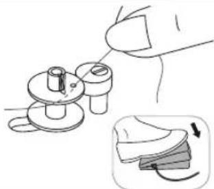
natural_image
Illustration of a hand turning a small mechanical component with a magnified inset showing the process (no text or symbols)- Hold the thread end to get ready to wind. Step on the foot controller gently as you hold the thread end. Allow it to wind a few revolutions slowly, then stop.
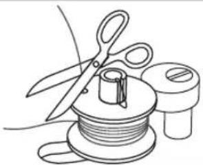
natural_image
Line drawing of a sewing machine tool with scissors, spool, and base (no text or symbols)- Trim the thread end close to the top of the bobbin, then resume winding by stepping on the foot control.

text_image
Diagram illustrating a sewing process with labeled parts A and B, showing a spool, pencil, and scissors.- The bobbin will stop winding when it is full. Lift your foot off the foot control. Push the bobbin to the left (A), then trim the thread and remove the bobbin from the spindle (B).

Turn power switch off before inserting or removing the bobbin.

natural_image
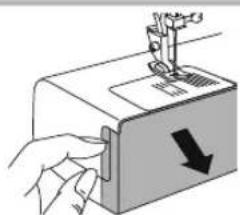
Illustration of a sewing machine needle stitching a fabric with a black arrow indicating direction (no text or symbols)- Take off the removable storage compartment.

natural_image
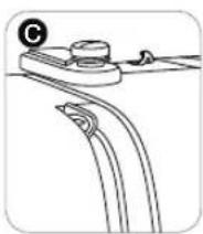
Illustration of a hand operating a sewing machine with a downward arrow indicating compression (no text or symbols present)- Open the hinged cover.
natural_image
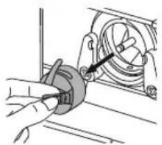
Hand inserting a small component into a mechanical housing (no text or symbols visible)- Pull the bobbin case latch to remove the bobbin case from the bobbin holder.

natural_image
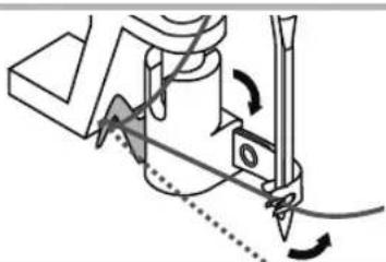
Diagram of a mechanical component with a rotating shaft and housing, showing internal structure and motion direction (no text or symbols)- Hold the bobbin case in one hand, then insert the bobbin so that the thread runs clockwise, as shown in the illustration.
text_image
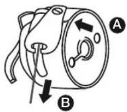
Diagram of a mechanical component with labeled parts A and B, showing directional arrows indicating movement or force.- First, bring the thread into the small slit (A) on the side of the bobbin case. Then, bring it underneath the metal guide, continuing until it is comes out of the opening at the bottom of the metal guide. You should feel it and hear it click in place. If it does not click in place, the machine will not sew. After clicking the thread in place, pull the thread in the direction shown (B).
natural_image
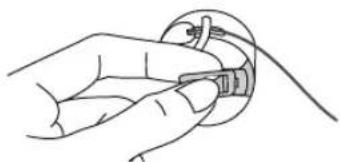
Line drawing of a hand holding a small object with a cable, no text or symbols present- Once the bobbin has been placed in the bobbin case, hold the bobbin case by the latch so that the latch is pointing toward you.

natural_image
Hand holding a circular component inside a mechanical device (no visible text or symbols)- Insert into the bobbin case holder so that the metal extension is positioned at 12 o'clock. You should feel the bobbin case become seated securely in place. Release the latch.
The bobbin case must be properly seated into the holder or the machine will not sew. After placing it into the holder and releasing the tab, if the bobbin case seems loose, if it falls to one side, or if it is not pushed all the way in, remove it. Hold it by the latch and reinsert it until it is securely in place.

Refer to illustration on base plate of machine.
2
GETTING READY TO SEW
Threading the Upper Thread

For safety, turn off the power before threading the machine.
natural_image
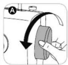
Hand holding a button with an arrow indicating clockwise motion (no text or symbols)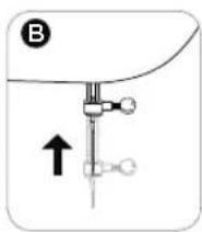
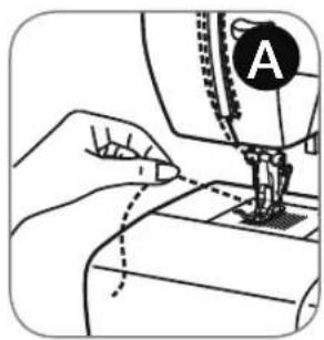
- Start by turning the handwheel (A) toward you to raise the needle (B) and the thread take up lever (C). You should be able to see the take up lever.

natural_image
Line drawing of a sewing machine needle with a curved arrow indicating rotation (no text or symbols)- → Raise the presser foot lifter. This is necessary in order for the machine to be threaded correctly.

natural_image
Hand holding a tool interacting with a mechanical component (no text or symbols visible)- Place the thread spool and spool cap onto the spool holder.

natural_image
Technical line drawing of a mechanical device with no visible text or symbols- Draw thread from the spool through the upper thread guide at the top of the machine. Hold the thread with both hands and pull it into the pretension guide.
natural_image
Mechanical assembly diagram showing a lever and bracket (no text or symbols)
natural_image
Diagram of a mechanical or fluidic device with directional arrows indicating flow or movement (no text or symbols)
natural_image
Diagram of a mechanical or electrical component with arrows indicating direction (no text or symbols)- (A) Bring the thread down the right channel, around the U-turn, and up the left channel. (B) At the top of the left channel, hook the thread from back to front through the slotted eye of the thread take-up lever. If the thread does not pass into the eye of the take-up lever, the machine will jam. After threading the take-up lever, bring the thread downward again. (C) Pass the thread behind the thin wire needle clamp guide and then down to the needle.
natural_image
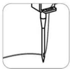
Simple line drawing of a pen or stylus with a curved base, no text or symbols present- If you want to thread the needle manually, thread it from front to back. Pull about 6-8 inches of thread to the back beyond the needle eye. Alternatively, you can use the Automatic Needle Threader to thread the eye of the needle (See Page 15).

For safety, turn off the power before using the automatic needle threader.

natural_image
Hand operating a mechanical switch with circular components (no text or symbols visible)- Raise the needle to its highest position by turning the handwheel toward you. If you turn the handwheel backward, the machine will jam when you start to sew.
natural_image
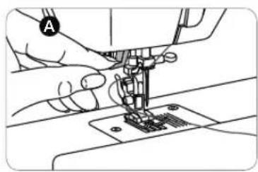
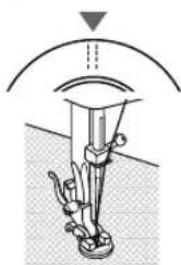
Close-up of hands operating a sewing machine on a workbench (no visible text or symbols)- Place your finger on the needle threader lever (A), then press lever as far down as it will go (B), bringing the hook pin into the eye of the needle.

natural_image
Close-up of hands operating a sewing machine with a downward arrow indicating a process (no text or symbols visible)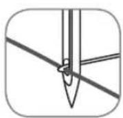

natural_image
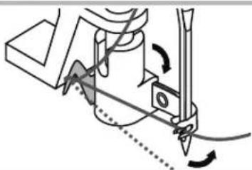
Mechanical assembly diagram showing a cutting tool interacting with a workpiece (no text or symbols visible)- The threader mechanism has a small hook pin that goes through the eye of the needle. Bring the thread around the guide at the left, and then place the thread under the hook pin.
natural_image
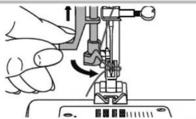
Illustration of a hand operating a sewing machine with a knob, showing mechanical components and motion direction (no text or symbols)- Release the needle threader lever and the thread tail at the same time. The hook pin will move back, creating a loop of thread at the back side of the needle.
natural_image
Close-up of a hand using a needle to apply a circular tool, with an arrow indicating direction (no text or symbols present)
natural_image
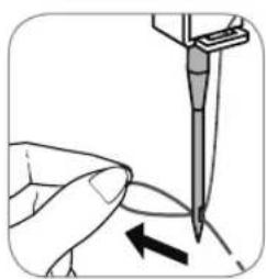
Simple line drawing of a pen or tool tip with a curved base (no text or symbols)- Pull the loop through the needle eye, until the thread tail passes through the needle.

Pull about 6-8" of thread to the back beyond the eye of the needle. This will help prevent the
needle from becoming unthreaded when you start to sew.
2
GETTING READY TO SEW
Drawing Up the Bobbin Thread

For safety, turn off the power before threading the machine.
natural_image
Line drawing of a hand using a sewing machine to mark the seam, with no visible text or symbols
natural_image
Hand holding a button with an arrow indicating rotation or adjustment (no text or symbols present)
natural_image
Pure diagram of a mechanical or fluidic device with no text, numbers, or symbols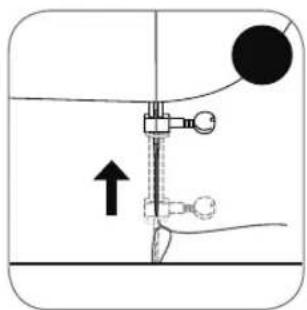
natural_image
Diagram of a mechanical device with a lever and adjustment mechanism, no text or symbols present- Hold the upper thread tail with the left hand (A). Turn the handwheel toward you (B), first lowering (C) and then raising the needle (D).

natural_image
Illustration of a sewing machine needle stitching a garment, showing the needle and handle (no text or symbols)- As you turn the handwheel, gently pull the upper thread, which will bring a loop of the bobbin thread up through the hole of the needle plate (E). Pull the loop to bring the bobbin thread end up through the opening in the needle plate.
If a loop doesn't pull up, turn the handwheel toward you one more time. If it still doesn't come up, check that the bobbin thread is not trapped by the removable storage compartment or the hinged cover.
natural_image
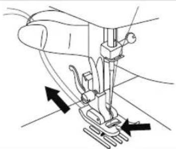
Line drawing of a sewing machine needle with arrows indicating fabric direction (no text or symbols)- Bring both threads under the presser foot and toward the back of the machine.
Now that your machine is threaded, we will show how to set up the machine for basic sewing techniques such as: sewing a straight stitch, sewing a decorative stitch, sewing a stretch stitch, sewing a buttonhole and sewing a button. With each technique, you have the opportunity to sew along.
For more information about the various stitches on your machine and how to use them, refer to the Stitch Reference Guide by visiting www.singerco.com.
Here are a few other tips that you may find helpful before you begin:
When unpacking the machine, you may have noticed some small traces of oil around the needle plate or presser foot area. If so, wipe off any excess oil with a soft, dry cloth before you start sewing.
The foot control is used to control the speed of your sewing. When you press down on the foot control, the machine will sew. The greater the pressure you place on the foot control, the faster the machine will sew. When you take your foot off the foot control, the machine will stop.
Needles are an important part of sewing. Using old, damaged or incorrect needles for your projects can affect sewing results. For information about which needle to use for your project, refer to the Stitch Reference Guide at www.singerco.com. For information on how to change the needle, see page 25.
Depending on the sewing technique you want to do, it may be necessary to change to a different presser foot. For information on how to do this, see page 26.
Review the page about Stitch Formation (see page 18). This will help you understand what the stitching should look like when you sew.
Use the thread cutter on the machine (see page 7) to trim thread tails when finished sewing. This is helpful because thread tails are left long enough so that the needle does not become unthreaded when you start sewing again.
3
START SEWING
Stitch Formation

text_image
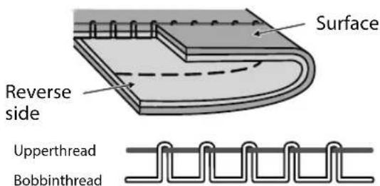
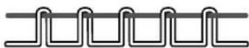
Surface Reverse side Upperthread Bobbinthread1. How Stitches Form
Stitches are formed when the upper thread and the bobbin thread interlock between the fabric layers. Stitching is well balanced when the needle thread appears on the top and the bobbin thread appears on the bottom.
text_image
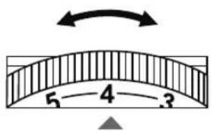
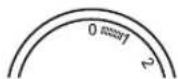
5—4—32. Thread Tension Dial
The Thread Tension Dial has a range of settings between 0 and 9. Most of your sewing will be done with your Thread Tension Dial set between 3 and 5. It can be adjusted to a higher number for more tension on the upper thread, if the upper thread seems too loose. It can be adjusted to a lower number for less tension on the upper thread, if the bobbin thread seems to be showing on the top side of the fabric.

text_image
Surface Reverse side Upperthread BobbinthreadAdjusting Tension
Thread tension can also be adjusted for various sewing techniques. For basting (see Appendix), you can loosen it to a lower number so that the stitches can easily be removed. For gathering, you can turn it to a higher number.
text_image
Surface Reverse side Upperthread Bobbinthread- → When you sew, if you see large loops on the underside of the fabric, this is actually an indication that the upper thread was not threaded correctly, as it has no tension controlling it. For information on how to correct this, see the Troubleshooting and Maintenance section of this manual.
text_image
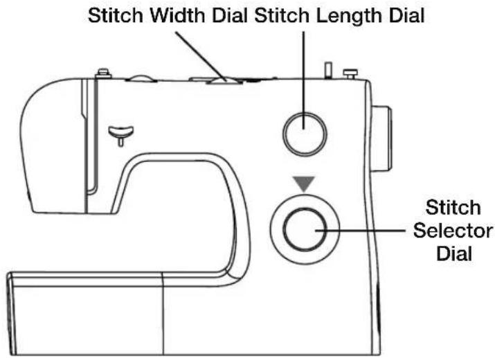
Stitch Width Dial Stitch Length Dial Stitch Selector Dial
natural_image
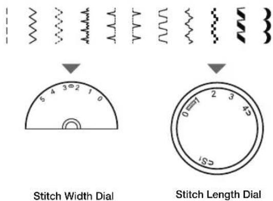
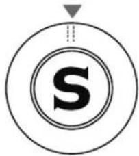
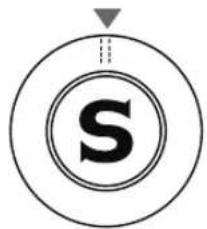
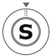
Abstract circular design with a central 'S' and concentric rings, no text or symbols present.The Stitch Selector Dial is used to select the stitch you want to sew. The dial can be turned to the left or to the right.
For Sewing the Black Stitch Patterns:
text_image
Stitch Width Dial Stitch Length Dial-
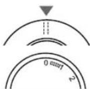
Turn the Stitch Selector Dial until it clicks in place under the blue arrow marking on the machine.
-
Set the Stitch Length Dial according to the length you want. It can be set anywhere between 0.5 and 4, with 4 being the longest setting.
-
For straight stitch sewing, the Stitch Width Dial should be set at the marking located on the Stitch Width Dial between 2 and 3.
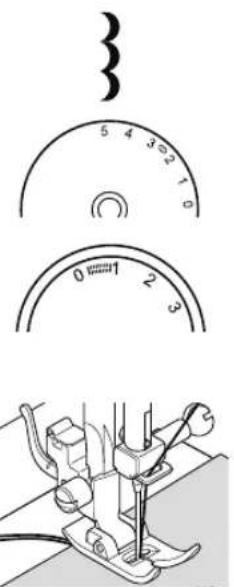
For Sewing the Blue Stitch Patterns:

text_image
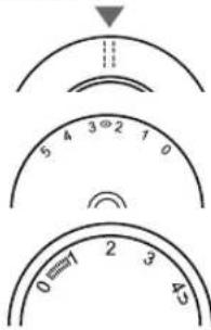
S1 Stitch Width Dial Stitch Length Dial-
Turn the Stitch Selector Dial until it clicks in place under the blue arrow on the machine.
-
Set the Stitch Length Dial so that the S1 is lined up with the blue arrow above this dial. This dial must be set at the S1 marking, or the stitch pattern will not sew.
-
Set the Stitch Width Dial to a wide setting, (3-5). If desired, you can set it to a lower setting, depending on the look you want.
For examples of stitch patterns and further instruction, see the Stitch Reference Guide at www.singerco.com.
3
START SEWING
Sewing a Straight Stitch
Stitch Selector Dial
Stitch Width Dial
Stitch Length Dial
natural_image
Circular icon with a stylized 'S' inside, no text or symbols present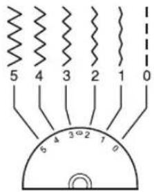
text_image
5 4 3 2 1 0 6 4 3 2 1 0
text_image
0.5 1 2 3 4 0=7 2 3 45 CS1A straight stitch is used for sewing seams and topstitching.
HOW TO:
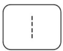
- Set the machine for Straight Stitch by setting the Stitch Selector Dial to straight stitch. (See Page 19)
- Set the Stitch Width Dial control to the center mark between 2 and 3. (See Page 19)
- The Stitch Length Dial control can be set at the stitch length that you desire. (See Page 19)
SEW ALONG:
text_image
5 4 3°2 1 0 0=1 2 3 4- Set the Stitch Selector Dial so that the straight stitch symbols are directly below the blue arrow.
- Set the Stitch Width Dial control so that the mark on the dial (between 2 and 3) is directly in front of the blue arrow on the machine.
- Set the Stitch Length Dial control so that the number 2 is directly below the blue arrow on the machine. This is an average stitch length setting for regular sewing.
- Place the fabric under the All Purpose Foot with the right-hand edge of the fabric lined up with the desired seam guide line on the right side of the needle plate. Lower the presser foot, then step on the foot control to begin sewing. Always make sure that the presser foot is lowered before you begin to sew. If you fail to do so, the machine will jam as you begin to sew. Start your seam by sewing 2 to 3 stitches. Press the Reverse Lever to sew backwards 2 to 3 stitches, which will lock the end of the seam so the stitches don't come undone. Release the Reverse Lever to sew forward again. Continue sewing the length of the seam. Press the Reverse Lever at the end of the seam and sew backwards 2 to 3 stitches. Release the Reverse Lever to sew forward again to finish.
natural_image
Line drawing of a sewing machine needle stitching on a textured surface (no text or symbols)
If you notice that the needle is not centered, the needle position can be adjusted by moving the Stitch Width Dial to the right or the left. Setting toward 0 will move it to the left and towards 5 will move it to the right. Placing the dial between 2 and 3 sets the needle in center position.

Use a slightly shorter stitch length for lightweight fabrics, finer threads and needles. Use a longer stitch length such as 3 or 4 for heavy weight fabrics.

It may be helpful to gently hold the thread tails with your left hand for the first few stitches, as this will help guide the fabric under the foot as you begin to sew.
Stitch Selector Dial
Stitch Width Dial
Stitch Length Dial
natural_image
Simple circular diagram with a central 'S' and a downward arrow, no text or symbols present.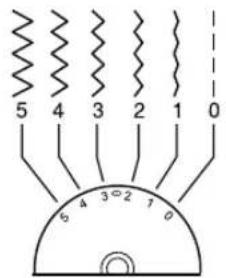
text_image
5 4 3 2 1 0 6 4 3°2 1 0
text_image
0.5 1 2 3 4 0 7 2 3 45 C51A decorative stitch is used for embellishing and adding flair to your sewing projects.
(Go to www.singerco.com to view other decorative stitches that can be used).
HOW TO:
- Set the machine to the desired stitch by setting the Stitch Selector Dial to one of the decorative stitches. (See Page 19)
- Set the Stitch Width Dial control between 2 and 5 depending on how wide you want your stitch to be. (See Page 19)
- Set the Stitch Length Dial between 0.5 and 3. (See Page 19)
SEW ALONG: Crescent Stitch
text_image
Technical diagram showing sewing machine components with numbered dial and needle mechanism- Set the Stitch Selector Dial, so that the Crescent Stitch setting is directly below the blue arrow.
- Set the Stitch Width Dial control so that number 5 is directly in front of the blue arrow.
- Set the Stitch Length Dial control so that number 1 is directly below the blue arrow.
- Place the fabric under the All Purpose Foot with the right-hand edge of the fabric lined up with the desired seam guide line on the right side of the needle plate. Lower the presser foot, then step on the foot control to begin sewing. Sew 2 to 3 stitches and then backstitch (see Page 20) to reinforce the seam.

Use a stabilizer (see Appendix) on the underside of the fabric if there is gathering or puckering as you sew. Decorative stitching can be used almost anywhere on your project!

It may be helpful to decrease the upper tension by 1 or 2 numbers when sewing decorative stitches. This will help prevent the bobbin thread from possibly showing on the top when sewing denser stitches.
3
START SEWING
Sewing a Stretch Stitch
Stitch Selector Dial
Stitch Width Dial
Stitch Length Dial


natural_image
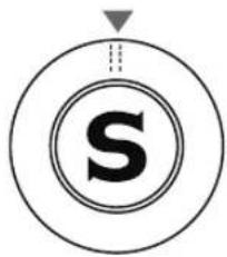
Circular diagram with a central 'S' and a small triangle above it, no text or symbols present.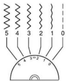
text_image
5 4 3 2 1 0 6 4 3 2 1 0
text_image
0.5 1 2 3 4 0=7 2 3 45 CS1A stretch stitch is used for knit fabrics. This type of seam will stretch with the fabric.
(Go to www.singerco.com to view other stretch stitches that can be used).
HOW TO:
- Set the machine to the desired stitch by setting the Stitch Selector Dial to one of the stretch stitch settings. (See Page 19)
- Set the Stitch Width Dial control between 2 and 5 depending on how wide you want your stitch to be. (See Page 19)
- Set the Stitch Length Dial to the Stretch S1 setting. (See Page 19)
SEW ALONG: Overedge Stitch

text_image
5 4 3 Ø2 1 0 cS1- Set the Stitch Selector Dial, so that the Overedge stitch setting is directly below the blue arrow.
- Set the Stitch Width Dial control so that number 5 is directly in front of the blue arrow.
- Set the Stitch Length Dial control so that the S1 selection is directly below the blue arrow.
- Place the fabric under the All Purpose Foot with the right-hand edge of the fabric lined up with the desired seam guide line on the right side of the needle plate. Lower the presser foot, then step on the foot control to begin sewing.

To obtain a Straight Stretch Stitch, simply move the Stitch Width Dial control to the marking between 2 and 3.
Stitch Selector Dial
Stitch Width Dial
Stitch Length Dial
3 4 2 1
natural_image
Circular diagram with a central 'S' and a dashed arrow pointing upward, no text or symbols present.
text_image
5 4 3 2 1 0 6 4 3 2 1 0
text_image
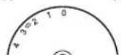
0.5 1 2 3 4 0=7 2 3 45 185This machine has a built-in buttonhole feature, allowing you to sew buttonholes in 4 easy steps. The Stitch Selector Dial shows the buttonhole settings in red.
HOW TO:
- Set the machine to the desired stitch by setting the Stitch Selector Dial to the buttonhole stitches. (See Page 19)
- Set the Stitch Width Dial control to the widest setting. (See Page 19)
- Set the Stitch Length Dial within the buttonhole range. (See Page 19)
SEW ALONG: Buttonhole Stitch
text_image
1 0 mm/7 2 3 5 4 3 2 1 0 1 2 3 4- Remove the All Purpose Foot and attach the Buttonhole Foot (see page 26). Set the Stitch Selector Dial so that step 1 of the buttonhole symbol is directly below the blue arrow.
- Set the Stitch Length Dial control so that the buttonhole range is directly below the blue arrow.
- Set the Stitch Width Dial control so that number 5 is directly in front of the blue arrow.
- Place the fabric under the foot so that the marking on the Buttonhole Foot aligns with the start of the buttonhole and that the center line marked on the fabric aligns with the center hole of the Buttonhole Foot.
- Lower the presser foot, and sew step 1 of the buttonhole until you arrive at the bottom of the buttonhole. Turn the hand wheel toward you to raise the needle out of the fabric.
- Set the Stitch Selector Dial so that step 2 of the buttonhole symbol is directly below the blue arrow. Sew 4 to 5 stitches across the bottom of the buttonhole; this is called a bar tack.
- Set the Stitch Selector Dial so that step 3 of the buttonhole symbol is directly below the blue arrow. Sew up the left side of the buttonhole.
- Set the Stitch Selector Dial so that step 4 of the buttonhole symbol is directly below the blue arrow. Sew 4 to 5 stitches across the top of the buttonhole to form the bar tack.
→ Use a stabilizer to support the stitches.
→ Slightly reducing your upper tension by 1 or 2 numbers will improve results.
→ Always test sew on a scrap piece of your fabric.
3
START SEWING
Sewing a Button
Stitch Selector Dial
Stitch Width Dial
Stitch Length Dial

natural_image
Technical line drawing of a mechanical assembly with no visible text or symbols
natural_image
Circular logo with a stylized 'S' inside, no text or symbols present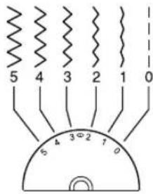
text_image
5 4 3 2 1 0 6 4 3 2 1 0
text_image
0.5 1 2 3 4 0=7 2 3 45 C51This machine includes a Button Sewing Foot, allowing you to attach buttons to your projects easily and quickly.
HOW TO:
- Set the machine to Straight Stitch by turning the Stitch Selector Dial to the Straight Stitch Symbol. (See Page 19)
- Set the Stitch Width Dial control to 0 to begin. (See Page 19)
- Set the Stitch Length Dial to 0 to begin. (See Page 19)
SEW ALONG: Attaching a Button
natural_image
Diagram of a mechanical device with a curved arrow and foot, no visible text or symbols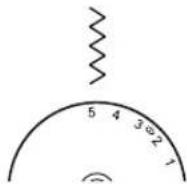

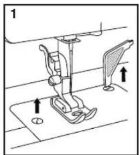
- Attach the Darning Plate to the needle plate directly below the presser foot. To do this line up the prongs on the underside of the Darning Plate with the holes in the needle plate. Push down to snap it in place.
- Remove the All Purpose Foot and attach the Button Sewing Foot. (See Page 26).
- Set the Stitch Length Dial control so that 0 is directly below the blue arrow.
- Set the Stitch Width Dial control so that number 0 is directly in front of the blue arrow.
- Set the Stitch Selector Dial so that the Straight Stitch setting is directly below the blue arrow.
- Place the button on the fabric, then line up the button directly under the front of the Button Foot so the 2 holes of the button appear in front of the foot. Turn the hand wheel towards you to make sure the needle clears the hole on the left. Step on the foot control and sew 3 to 4 securing stitches. Raise the needle out of the fabric.
- Set the Stitch Selector Dial so that the Zig Zag setting is directly below the blue arrow.
- Set the Stitch Width Dial control so that number 5 is directly in front of the blue arrow. Turn the hand wheel toward you to make sure that the needle clears both the left and right holes of the button. Adjust the Stitch Width Dial if necessary. Sew 10 to 12 stitches.
- Set the Stitch Selector Dial so that the Straight Stitch setting is directly below the blue arrow.
- Set the Stitch Width Dial control so that number 0 is directly in front of the blue arrow. Sew 3 to 4 stitches to secure the stitching.

Turn the machine off before changing the needle.
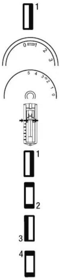
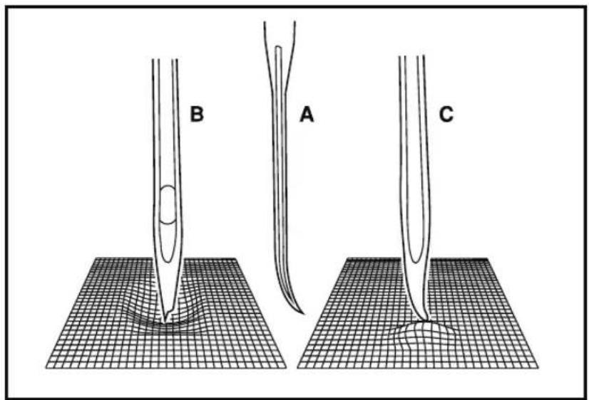
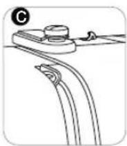
Change the needle regularly, especially if it is showing signs of wear resulting in sewing problems. Needles can show signs of wear when you see snags in the fabric or hear a slight popping sound as you are sewing. If the needle becomes bent (A), the point becomes damaged (B) or the needle becomes dull (C), you should replace it with a new needle and discard the old one.
Generally, the needle should be replaced after every 4 projects or approximately every 16 hours of sewing time.
It is also important to use the right needle for the fabric you are sewing. (Go to www.singerco.com to view the Stitch Reference Guide) For best results, use SINGER® branded needles in your SINGER® sewing machine.
text_image
B A CLoosen the needle clamp screw (A) by turning the screw toward you. Remove and discard the old needle. Insert the new needle, making sure that the flat side of the top part of the needle is facing the back of the machine (B). Insert the new needle as far up as it will go (C and D). Tighten the needle clamp screw (A) securely by turning it toward the back.
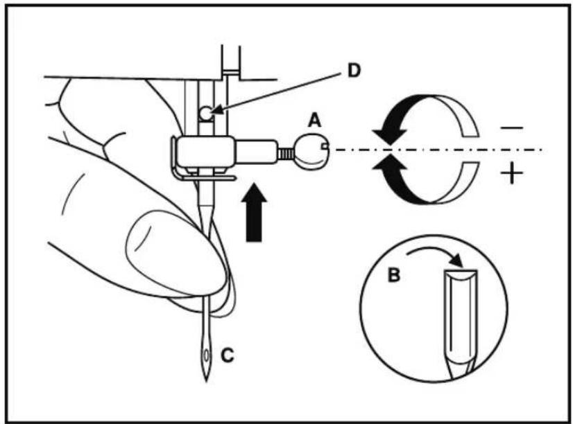
text_image
D A C B -3
START SEWING
Changing the Presser Foot

Turn machine off before changing the presser foot.
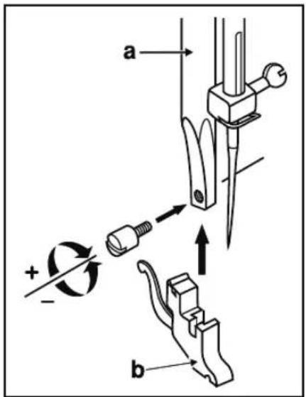
text_image
Technical diagram of a sewing machine with labeled parts and directional arrows indicating motion or assembly.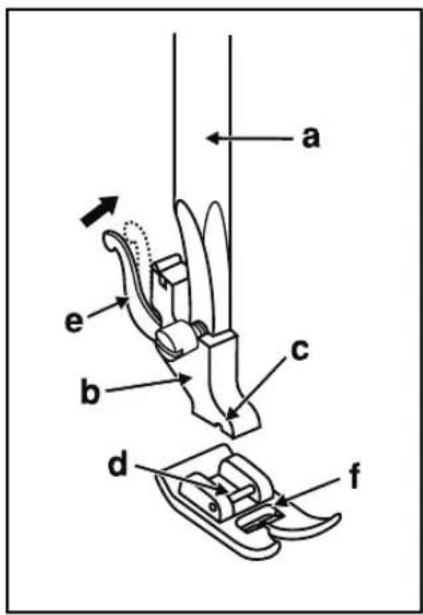
text_image
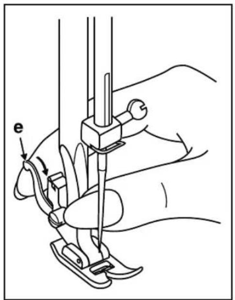
a e b c d fBefore changing the presser foot, raise the presser foot lifter.
The presser foot holder (b) is attached to the presser bar (a). The presser foot (f) has a presser foot pin (d) that connects to the presser foot holder, sometimes called a shank (b). The shank has a groove (c) on its underside, which connects it to the presser foot.
To remove a presser foot from the shank, press the lever (e) at the back of the shank. The foot will release. To attach a presser foot to the shank, line up the presser foot pin (d) underneath the groove (c) on the shank (b). Lower the presser foot lifter, bringing the shank's groove down over the pin. The foot will snap on.
Some optional presser feet require you to remove the shank from the machine. To remove the shank from the machine (see below) loosen and remove the screw that holds the presser foot onto the presser bar (a), then remove the shank (b). To replace the shank, set the shank onto the presser bar, then replace the screw.

This machine has a low shank with snap-on presser feet. When shopping for optional presser and attachments for your machine, look for low-shank, snap-on style.
text_image
a + - b- Thread Loops on Underside of Fabric
- Bobbin Thread Showing on Top of Fabric
- Upper Thread Breaking
- Thread is Shredding
- Thread Bunching at Beginning
- Skipping Stitches
- Bobbin Winding Difficulties
- Bobbin Thread Breaking
- Needles Breaking
- Stitches Distorted
- Fabric Puckers
- Fabric Is "Tunneling" Under Stitches
- Machine Not Feeding Fabric
- Needle Threader Not Working
- Loud Noise When Sewing
- Machine Will Not Run
1. THREAD LOOPS ON UNDERSIDE OF FABRIC
Possible Cause: Thread looping on the underside of the fabric is always an indication that the upper thread is not correctly threaded. This happens when the upper thread is not correctly placed in the tension mechanism and has not been threaded through the take up lever.
Solution: Rethread machine, making sure to first raise the presser foot lifter before starting to thread, so thread can be properly seated in the tension mechanism and take up lever. (See Page 14)
To know if you have rethreaded the machine correctly, try this simple test:
- Raise the presser foot lifter and thread the top of the machine.
- Thread the needle, but don't put the thread under the presser foot yet. As you pull the upper thread to the left, it should pull freely
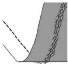
natural_image
Abstract diagram showing a curved line intersecting a shaded region with a grid-like pattern (no text or symbols)- Put the presser foot lifter down. As you pull the upper thread to the left, you should feel resistance. This means you are threaded correctly.
- Put the thread under the presser foot, and then draw up the bobbin thread. Slip both thread tails under the presser foot towards the back. Lower presser foot and begin sewing.
If you put the presser foot lifter down, but the thread still pulls freely (you feel no difference whether the presser foot is up or down), this means you have threaded incorrectly. Remove the upper thread and rethread the machine.
2. BOBBIN THREAD SHOWING ON TOP OF FABRIC
Possible Cause: Top thread tension too tight
Solution: Reduce upper thread tension. (See Page 18)
Possible Cause: Thread path is obstructed, putting extra tension on top thread
Solution: Check that the top thread path is not obstructed and thread is moving freely through the thread path. (See Page 14)
Possible Cause: Bobbin thread not in bobbin case tension
Solution: Rethread bobbin. (See Page 13)
4
TROUBLESHOOTING AND MAINTENANCE
Troubleshooting
3. UPPER THREAD BREAKING
Possible Cause: Thread path obstructed
Solution: Check if thread is caught on thread spool (rough spots on the spool itself) or behind spool pin or spool cap (if the thread has fallen behind the spool cap and therefore cannot feed freely through the machine path). (See Page 14)
Possible Cause: Machine is not threaded correctly
Solution: Remove upper thread completely, raise presser foot lifter, rethread machine making sure thread is in take-up lever (raise take up lever to its highest position by turning hand wheel toward you. (See Page 14)
Possible Cause: Upper tension too tight
Solution: Reduce upper thread tension. (See Page 18)
4. THREAD IS SHREDDING
Possible Cause: Thread is old or poor quality
Solution: Rethread the top of the machine and bobbin with good quality thread. (See Page 14)
Possible Cause: The needle is either worn or old, or it is the wrong style or size for the thread being used. Though it may seem that the machine is shredding the thread, it is usually the needle causing this. If the needle is old or worn out, or if the needle is too small for the thickness of thread, the eye of the needle can cause the thread to shred.
Solution: Change to a fresh needle in the correct size for the thickness/weight of thread being used. (See Page 25)
5. THREAD BUNCHING AT BEGINNING
Possible Cause: Top & bobbin threads have not been properly placed underneath presser foot before starting to sew.
Solution: Ensure that both the top thread and the bobbin thread are under the presser foot and toward the back before starting to sew. (See Page 20)
Possible Cause: Sewing was started with no fabric under the presser foot.
Solution: Place fabric under foot, making sure that needle comes down into fabric; lightly hold both thread tails for first few stitches. (See Page 20)
6. SKIPPING STITCHES
Possible Cause: Needle inserted incorrectly
Solution: Check that flat side of needle top is toward back of machine and needle is up as far as it can go, then tighten needle clamp screw. (See Page 25)
Possible Cause: Wrong needle for fabric sewn
Solution: Use correct style & size of needle for fabric. (Go to www.singerco.com to view the Stitch Reference Guide)
Possible Cause: Bent, dull or damaged needle
Solution: Discard needle and insert new needle. (See Page 25)
7. BOBBIN WINDING DIFFICULTIES
Possible Cause: Bobbin thread loosely wound on bobbin
Solution: Rewind bobbin, making sure that the thread is placed snuggly in the bobbin winding tension disk. (See Page 12)
Possible Cause: Bobbin winding spindle not fully engaged, therefore bobbin not winding
Solution: Check that the bobbin winding spindle has been fully engaged before starting to wind. (See Page 12)
Possible Cause: Bobbin is winding sloppily because thread end not held at beginning of winding process.
Solution: Before starting to wind, hold the thread tail (coming out of the bobbin) securely, allow the bobbin to partially fill, then stop to trim the thread tail close to the bobbin. (See Page 12)
8. BOBBIN THREAD BREAKING
Possible Cause: Bobbin threaded incorrectly
Solution: Check that bobbin is placed correctly in the bobbin holder. (See Page 13)
Possible Cause: Bobbin wound too full or unevenly
Solution: Bobbin thread may not have been correctly placed into bobbin winding tension disk during the bobbin winding process. (See Page 12)
Possible Cause: Dirt or lint in bobbin holder
Solution: Clean bobbin holder. (See Page 32)
Possible Cause: Wrong bobbins being used
Solution: Use SINGER® bobbins that are the same style as those that come with the machine – don't substitute. Your machine comes with SINGER® Class 15 transparent bobbins.
9. NEEDLES BREAKING
Possible Cause: Bent, dull or damaged needle
Solution: Discard needle, insert new needle. (See Page 25)
Possible Cause: Wrong size needle for fabric
Solution: Insert appropriate needle for fabric type. (Go to www.singerco.com to view the Stitch Reference Guide)
Possible Cause: Machine not threaded correctly
Solution: Rethread the machine completely. (See Page 14)
Possible Cause: "Pushing" or "pulling" fabric
Solution: Don't manually push/pull fabric in order to sew, but allow the machine's feed teeth to draw fabric under the presser foot as you guide it. (See Page 20)
4
TROUBLESHOOTING AND MAINTENANCE
Troubleshooting
10. STITCHES DISTORTED
Possible Cause: "Pushing" or "pulling the fabric
Solution: Don't manually push/pull fabric in order to sew, but allow the machine's feed teeth to draw fabric under presser foot as you guide it.
Possible Cause: Incorrect stitch length setting
Solution: Check manual for correct stitch length/width settings. (Go to www.singerco.com to view the Stitch Reference Guide)
Possible Cause: Stabilizer may be needed for technique.
Solution: Place stabilizer underneath fabric. (See Appendix)
11. FABRIC PUCKERS
Possible Cause: Top thread tension is too tight.
Solution: Reduce the top thread tension. (See Page 18)
Possible Cause: Stitch length is set too short for the fabric being sewn.
Solution: Increase stitch length. (Go to www.singerco.com to view the Stitch Reference Guide)
Possible Cause: Wrong style needle for fabric type
Solution: Use correct needle style. (Go to www.singerco.com to view the Stitch Reference Guide)
Possible Cause: Needle too large for fabric
Solution: Change to smaller size needle. (See Page 25)
12. FABRIC IS "TUNNELING" UNDER STITCHES
Possible Cause: Fabric is not properly stabilized for the density of the stitches (for example, satin stitch applique).
Solution: Add a fabric stabilizer underneath the fabric to help keep the stitches from tunneling in together, forming a puckered ridge in fabric. (See Appendix)
13. MACHINE NOT FEEDING FABRIC
Possible Cause: Presser foot lifter has not been lowered onto fabric after threading.
Solution: Lower the presser foot lifter before starting to sew. Don't "push" or "pull" the fabric as you sew.
Possible Cause: Feed dogs are covered by Darning Plate.
Solution: If the feed dogs have been covered, the Darning Plate needs to be removed to resume regular sewing.
Possible Cause: Stitch length is set at zero.
Solution: Increase stitch length setting.
14. NEEDLE THREADER NOT WORKING
(for models with built-in automatic needle threader)
Possible Cause: Needle not in correct position
Solution: Raise needle to its highest position by turning hand wheel toward you. (See Page 15)
Possible Cause: Needle inserted incorrectly
Solution: Needle all the way up in needle clamp (See Page 25)
Possible Cause: Needle is bent
Solution: Remove bent needle, insert new needle. (See Page 25)
Possible Cause: Hook pin damaged
Solution: Needle Threader needs replacement; contact authorized SINGER® service center: Visit www.singerco.com.
15. LOUD NOISE WHEN SEWING
Possible Cause: Thread not in take-up lever
Solution: Rethread the machine, making sure the take up lever is in its highest position so thread goes in the eye of the take up lever – turn machine hand wheel toward you to raise the take up lever to its highest position for threading. (See Page 14)
Possible Cause: Thread path obstructed
Solution: Check that thread is not caught on the thread spool or behind the spool cap. (See Page 14)
16. MACHINE WILL NOT RUN
Possible Cause: Bobbin winding spindle is engaged when you try to sew.
Solution: Disengage bobbin winding spindle. (See Page 12)
Possible Cause: Power cord and/or foot controller not plugged in correctly
Solution: Make sure power cord/foot control are correctly seated in machine and power supply. (See Page 11)
Possible Cause: Wrong bobbins being used
Solution: Use only SINGER® branded bobbins that are same style as those that come with machine. (See Page 10)
4
TROUBLESHOOTING AND MAINTENANCE
Maintenance
Cleaning the Feed Teeth and Hook Area

Before cleaning the machine, disconnect the power supply by removing the plug from the electrical outlet. Turn the hand wheel to raise the needle to its highest position. Raise the presser foot lifter.
natural_image
Technical line drawing of a sewing machine with no visible text or symbols
natural_image
Mechanical assembly diagram showing a hand using a tool to install components on a rotating base (no text or symbols visible)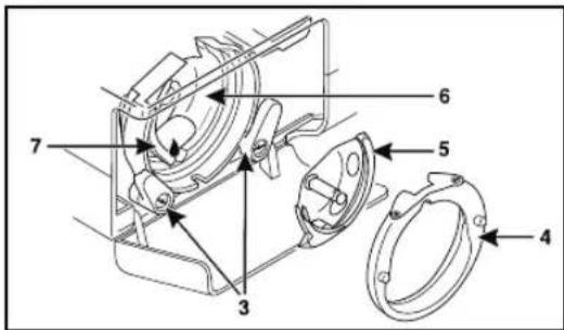
text_image
Technical diagram of a mechanical assembly with numbered components for identificationTo ensure the best possible operation of your machine, it is necessary to keep the essential parts clean. For daily machine use, it is recommended that you clean and oil the machine weekly.
- Open the hinged front cover. Unscrew the needle plate screws (1) with the screw driver and remove the needle plate.
- Remove the bobbin case from the bobbin case holder, Use the lint brush (2) to clean around the feed dogs.
- Push the two hook retaining arms (3) outward. Remove the hook race cover (4) and hook (5). Clean them with a soft cloth.
- Put one drop of sewing machine oil on the center pin of the hook and hook race (6).
- Turn the hand wheel toward you until the hook race looks like a half-moon, on the left side of the machine (7).
- Holding the hook (5) by its center pin, replace it so it forms a half-moon on the right side.
- Replace the hook race cover back into position.
- Push the hook retaining arms back into position.
- Insert the bobbin case and bobbin.
- Replace the needle plate and needle plate screws, then tighten the screws securely with the screwdriver.
Sewing Light
This machine is equipped with a durable LED illumination, which is expected to last for the lifetime of the equipment.
Please contact a local service agent, should the lamp nevertheless require to be replaced.
Backstitch
Backstitching is most commonly used at the beginning and ending of seams to lock the stitching so it does not come undone. Start sewing the beginning of the seam about 3-4 stitches, then sew in reverse for 3-4 stitches. Start sewing forward again and continue sewing the seam to the end, then sew in reverse 3-4 stitches, then forward again to finish.
Basting
Basting is temporary stitching, sewn using a long straight stitch and reduced tension. This temporary stitching holds fabrics together, but is intended to be removed. For example, basting the side seams of a skirt to check the fit, then the final seam is sewn and the basting stitch is removed.
Free Arm
In order to sew small, tubular projects such as a pant leg, sleeve cuff, etc, you will need to take the removable storage compartment off the machine, giving access to the free arm.
Interfacing
Interfacing is specially designed material, sewn between fabrics, used to provide additional structure to parts of a garment, for example, cuffs, collars, plackets, etc. It can be used for buttonholes to help keep the fabric stable while sewing.
Raw Edge
The raw edge of the fabric refers to the cut edge and usually becomes the edge of the seam allowance.
Seam
A seam is stitching that joins two fabrics together, includes the main stitching line and the seam allowance.
Seam Allowance
The seam allowance is the amount of fabric between the seam stitches and the raw edge of the fabric. The most popular seam allowance are 5/8" and 1/2".
Seam Finish
Seam finishing is stitching used to keep a raw edge from unraveling or fraying.
Stabilizer
Stabilizer is special material used to provide additional support for stitches for special techniques such as decorative machine stitching, appliqué, buttonholes and more.
Topstitching
Topstitching is straight stitching that appears on the top side of the fabric, used for adding strength, embellishment or both.
Please note that on disposal, this product must be safely recycled in accordance with relevant National legislation relating to electrical/electronic products. Do not dispose of electrical appliances as unsorted municipal waste, use separate collection facilities. Contact your local government for information regarding the collection systems available. When replacing old appliances with new ones, the retailer may be legally obligated to take back your old appliance for disposal free of charge.
If electrical appliances are disposed of in landfills or dumps, hazardous substances can leak into the groundwater and get into the food chain, damaging your health and well-being.

SINGER®

SINGER®
natural_image
Line drawing of a sewing machine with no text or symbolsSINGER is sewing made easy.™
text_image
Technical diagram of a sewing machine with numbered parts and an inset close-up view of the component.text_image
Labeled diagram of a sewing machine with numbered parts and an inset showing internal componentsnatural_image
Line drawing of a hand operating a sewing machine with a sewing machine needle inserted (no text or symbols)
natural_image
Technical line drawing of a mechanical housing or enclosure with an arrow indicating rotation (no text or symbols present)text_image
Diagram showing connection between a device labeled 'A' and an electrical outlet with a switch, connected to a panel with an outlet panel.
text_image
a b
natural_image
Line drawing of a shoe being held with a cable, showing a curved object and an arrow indicating motion (no text or symbols)natural_image
Illustration of a hand using a tool to adjust a component, showing arrows indicating motion (no text or symbols present)text_image
Technical diagram of a mechanical device with labeled components A, B, and C, showing internal components and directional arrows.text_image
Diagram showing a mechanical assembly with labeled parts A and B, likely illustrating a valve or adjustment mechanism.natural_image
Illustration of a hand using a sewing machine to adjust a small object, with an inset showing the same part (no text or symbols present)natural_image
Line drawing of a sewing machine tool with scissors, spool, and base (no text or symbols)text_image
Diagram showing two steps of fabric cutting: (A) a roll with scissors, (B) a spool with scissors, illustrating the process.natural_image
Illustration of a sewing machine needle stitching a fabric with a black arrow indicating direction (no text or symbols)natural_image
Illustration of a sewing machine needle with a hand inserting a black arrow (no text or symbols)natural_image
Hand holding a mechanical component with a tool inserted, next to a circular component (no text or symbols visible)natural_image
Diagram of a mechanical component with a rotating shaft and housing, showing a left-side assembly and a downward arrow (no text or symbols)text_image
Diagram of a mechanical component with labeled parts A and B, showing directional arrows indicating movement or force.natural_image
Line drawing of a hand holding a small object with a cable, no text or symbols presentnatural_image
Line drawing of a hand holding a circular component inside a mechanical device (no text or symbols visible)natural_image
Hand holding a circular object with an arrow indicating rotation or movement (no text or symbols)

natural_image
Line drawing of a sewing machine needle with a curved arrow indicating rotation (no text or symbols)natural_image
Hand holding a tool interacting with a mechanical component (no text or symbols visible)natural_image
Technical diagram of a mechanical device with internal components and directional arrows (no text or symbols)natural_image
Mechanical diagram showing a lever and pivot mechanism (no text or symbols)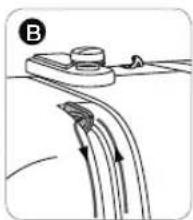
natural_image
Diagram of a mechanical or fluidic device with curved flow lines and a labeled component (B), no readable text or symbols present.
natural_image
Diagram of a mechanical or electrical component with arrows indicating motion, no visible text or symbolsnatural_image
Simple line drawing of a pen tip and ruler (no text or symbols)natural_image
Hand operating a mechanical switch with circular components (no text or symbols visible)natural_image
Close-up of hands operating a sewing machine on a workbench (no visible text or symbols)natural_image
Close-up of hands operating a sewing machine with a downward arrow indicating a process (no text or symbols visible)
natural_image
Mechanical assembly diagram showing a cutting tool interacting with a workpiece (no text or symbols)natural_image
Illustration of a hand operating a sewing machine with a curved arrow indicating motion (no text or symbols present)natural_image
Close-up of a hand holding a needle tip, with an arrow indicating direction (no text or symbols)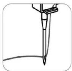
natural_image
Simple line drawing of a pen or stylus with a curved base, no text or symbols presentnatural_image
Line drawing of a hand using a sewing machine to press fabric (no text or symbols)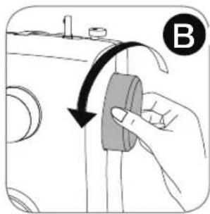
natural_image
Hand holding a button with an arrow indicating rotation or adjustment (no text or symbols present)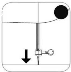
natural_image
Pure diagram of a mechanical or fluidic device with no text, numbers, or symbols
natural_image
Diagram of a mechanical device with a lever and adjustment mechanism, no text or symbols presentnatural_image
Diagram of a sewing machine needle stitching a garment, showing the needle and handle (no text or symbols)natural_image
Line drawing of a sewing machine needle with arrows indicating fabric direction (no text or symbols)natural_image
Pure technical diagram of a curved mechanical component with no visible text, numbers, or symbolsSuperficie

natural_image
Cross-sectional diagram of a layered structure with labeled components (no text or symbols)Superficie

Lado
reverso
Hilo superior
Hilo bobina

natural_image
Diagram of a curved mechanical component with internal features and dashed line indicating a path (no text or symbols)Superficie
text_image
Diagram showing waveform patterns and a dial with numerical scale and 'GSI' label, likely from an electronic or signal processing context.Perilla Ancho Puntada Perilla Largo Puntada
natural_image
Circular diagram with a central 'S' and a downward arrow, no text or symbols present.
text_image
5 4 3 2 1 0 6 4 3 2 1 0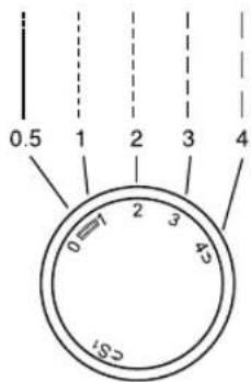
text_image
0.5 1 2 3 4 0=7 2 3 45 CS1natural_image
Line drawing of a sewing machine needle stitching on a textured surface (no text or symbols)
natural_image
Simple circular diagram with a central 'S' and a downward arrow, no text or symbols present.
text_image
5 4 3 2 1 0 6 4 3 2 1 0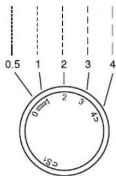
text_image
0.5 1 2 3 4 0=7 2 3 45 C51text_image
Technical diagram showing sewing machine components with scale and pointer, alongside a separate schematic symbol.text_image
Technical diagram showing three labeled circular components with internal symbols and numbered terminals, likely representing a mechanical or electrical component layout.natural_image
Line drawing of a sewing machine needle stitching on a textured surface (no text or symbols)
natural_image
Circular diagram with a central 'S' and a downward-pointing arrow, no text or symbols present.
text_image
5 4 3 2 1 0 6 4 3 2 1 0
text_image
0.5 1 2 3 4 0=7 2 3 45 185natural_image
Diagram of a mechanical device with a curved arrow indicating motion or force, no text or symbols present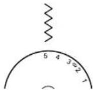
text_image
Technical diagram of a sewing machine with labeled parts and directional arrows indicating motion or assembly.
text_image
a e b c d fnatural_image
Abstract diagram showing a curved line intersecting a shaded region with a grid-like pattern (no text or symbols)natural_image
Technical line drawing of a sewing machine with no visible text or symbols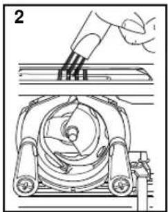
natural_image
Technical line drawing of a mechanical assembly with a hand holding a tool above a rotating component (no text or symbols)
text_image
Technical diagram of a mechanical device with numbered components for identificationnatural_image
Line drawing of a sewing machine with no text or symbolsMANUEL D'INSTRUCTION
2263
SINGER is sewing made easy.™
text_image
Technical diagram of a sewing machine with numbered parts and an inset view of the needle mechanism.text_image
Labeled diagram of a sewing machine with numbered parts and an inset showing internal componentsnatural_image
Line drawing of a hand operating a sewing machine with a foot, no text or symbols present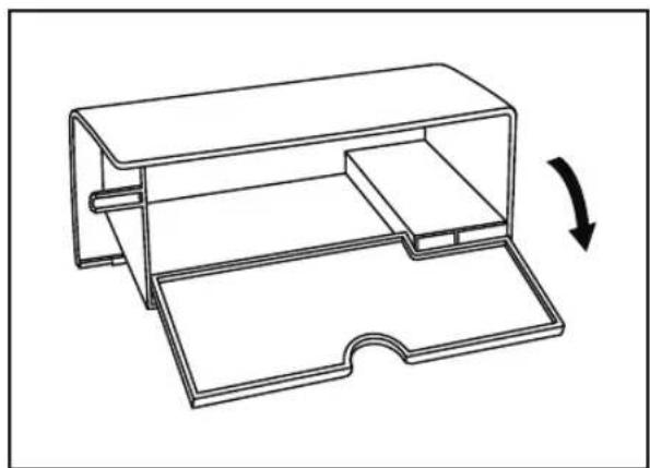
natural_image
Technical line drawing of a mechanical housing or enclosure with an arrow indicating rotation (no text or symbols present)text_image
Diagram showing connection between a device labeled 'A' and an electrical outlet with a switch, connected to a panel with an outlet panel.
text_image
a b
natural_image
Line drawing of a shoe being inserted into a clip, with a black arrow indicating the direction (no text or symbols)natural_image
Illustration of a hand using a tool to adjust a component with arrows indicating direction (no text or symbols present)text_image
Technical diagram of a mechanical device with labeled components A, B, and C, showing internal components and directional arrows.text_image
Diagram showing a mechanical assembly with labeled parts A and B, likely illustrating a valve or adjustment mechanism.natural_image
Illustration of a hand using a tool to adjust a mechanical component, with an inset showing the same part (no text or symbols present)natural_image
Line drawing of a sewing machine tool with scissors, spool, and base (no text or symbols)text_image
Diagram showing two labeled parts (A and B) of a sewing machine tool, including a spool, scissors, and a cylindrical component.natural_image
Illustration of a sewing machine needle stitching a fabric (no text or symbols visible)- Retirez le compartiment de rangement amovible.
natural_image
Illustration of a sewing machine needle being inserted into a box, with a downward arrow indicating the process (no text or symbols present)natural_image
Hand holding a mechanical component with a screwdriver inserted, no visible text or symbolsnatural_image
Diagram of a mechanical component with a rotating shaft and housing, showing a left-side assembly and a downward arrow (no text or symbols)text_image
Diagram of a mechanical component with labeled parts A and B, showing directional arrows indicating movement or force.natural_image
Line drawing of a hand holding a small object with a cable, no text or symbols presentnatural_image
Hand holding a circular component inside a mechanical device (no visible text or symbols)natural_image
Hand holding a gray object with an arrow indicating rotation or movement (no text or symbols)
natural_image
Line drawing of a sewing machine needle with a hand operating the base (no text or symbols)natural_image
Hand holding a tool applying material to a mechanical component (no text or symbols visible)natural_image
Technical diagram of a mechanical device with internal components and directional arrows (no text or symbols)natural_image
Diagram of a mechanical device with a lever and bracket (no text or symbols)
natural_image
Diagram of a mechanical or fluidic component with directional arrows indicating flow or movement (no text or symbols)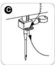
natural_image
Diagram of a mechanical or electrical component with arrows indicating motion or force direction (no text or symbols)natural_image
Simple line drawing of a pen tip with a curved base (no text or symbols)natural_image
Hand operating a mechanical switch with circular components (no text or symbols visible)natural_image
Line drawing of hands operating a sewing machine on a workbench (no text or symbols visible)natural_image
Close-up of hands operating a sewing machine with a downward arrow indicating a process (no text or symbols visible)
natural_image
Mechanical assembly diagram showing a cutting tool interacting with a workpiece (no text or symbols)natural_image
Illustration of a hand operating a sewing machine with a finger, showing the mechanism and control buttons (no text or symbols present)natural_image
Close-up of a hand holding a needle or screwdriver with an arrow indicating direction (no text or symbols)
natural_image
Simple line drawing of a pen or stylus tip with a curved base (no text or symbols)natural_image
Illustration of a sewing machine needle stitching a piece, with no visible text or symbolsnatural_image
Line drawing of a sewing machine needle with arrows indicating fabric direction (no text or symbols)natural_image
Abstract circular design with a stylized 'S' inside, no text or symbols present.text_image
Diagram showing waveform patterns and a dial with numerical scale and pointer, likely illustrating signal or measurement concepts.natural_image
Circular diagram with a central 'S' and a downward arrow, no text or symbols present.natural_image
Line drawing of a sewing machine needle stitching on a textured surface (no text or symbols)natural_image
Circular diagram with a central 'S' and a dashed arrow pointing upward, no text or symbols present.text_image
Technical diagram showing sewing machine components with degree markings and a separate close-up view of the needle.natural_image
Circular diagram with a central 'S' and a dashed arrow pointing upward, no text or symbols present.natural_image
Technical line drawing of a mechanical assembly with no visible text or symbolsnatural_image
Circular diagram with a stylized 'S' inside, no text or symbols presenttext_image
Technical diagram of a sewing machine with labeled parts and directional arrows indicating movement or positioning.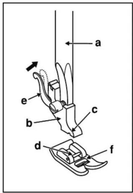
text_image
a e b c d fnatural_image
Abstract diagram showing a curved line intersecting a shaded region with a dashed diagonal line (no text or symbols)natural_image
Technical line drawing of a sewing machine with no visible text or symbols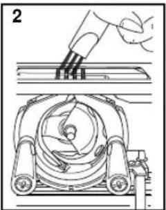
natural_image
Diagram of a mechanical device with a hand holding a tool above it, showing internal components and motion (no text or symbols)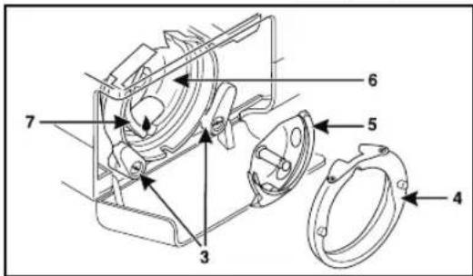
text_image
Technical diagram of a mechanical assembly with numbered components for identification230126112 E/S/F - Printed in Vietnam on environmentally friendly paper