
DH 24DV - Drill HITACHI - Free user manual and instructions
Find the device manual for free DH 24DV HITACHI in PDF.


| Product Type | Cordless Hammer Drill |
| Brand | Hitachi |
| Model | DH24DV |
| Weight | 4.0 kg |
| Power Supply | Rechargeable Ni-MH 24 V battery |
| Battery Capacity | 3.0 Ah (EB2430HA) or 3.3 Ah (EB2433X) |
| Charger | UC24YFB, 24 V |
| No-load Speed (Save Mode) | 0 - 500 min⁻¹ |
| No-load Speed (Power Mode) | 0 - 1000 min⁻¹ |
| Impact Rate (Save Mode) | 0 - 2200 min⁻¹ |
| Impact Rate (Power Mode) | 0 - 4500 min⁻¹ |
| Drilling Capacity – Concrete | 24 mm |
| Drilling Capacity – Steel | 13 mm |
| Drilling Capacity – Wood | 30 mm |
| Screw Driving (Wood) | 6.2 mm (diameter) × 40 mm (length) |
| Operating Modes | Rotation + Hammering, Rotation only |
| Power Adjustment | Save Mode / Power Mode |
| Side Handle | Yes (included) |
| Depth Gauge | Yes (included) |
| Carrying Case | Plastic (included) |
| Motor Protection | Automatic brush stop |
| Sound Pressure Level | 92 dB(A) |
| Sound Power Level | 103 dB(A) |
| Lubrication | Specific grease FG-6A |
Frequently Asked Questions - DH 24DV HITACHI
User questions about DH 24DV HITACHI
0 question about this device. Answer the ones you know or ask your own.
Ask a new question about this device
Download the instructions for your Drill in PDF format for free! Find your manual DH 24DV - HITACHI and take your electronic device back in hand. On this page are published all the documents necessary for the use of your device. DH 24DV by HITACHI.
USER MANUAL DH 24DV HITACHI
natural_image
Line drawing of a compact pistol with internal components and no visible text or symbolsRead through carefully and understand these instructions before use. Diese Anleitung vor Benutzung des Werkzeugs sorgfältig durchlesen und verstehen. Lire soigneusement et bien assimiler ces instructions avant usage. Prima dell'uso leggere attentamente e comprendere queste instruzioni. Deze gebruiksaanwijzing s.v.p. voor gebruik zorgvuldig doorlezen. Leer cuidadosamente y comprender estas instrucciones antes del uso. Antes de usar, leia com cuidado para assimilar estas instruções. Διαβάστε προσεκτικά και κατανοήσετε αυτές τις οδηγίες πριν τη χρήση.
Handling instructions Bedienungsanleitung Mode d'emploi Instruzioni per l'uso Gebruiksaanwijzing Instrucciones de manejo Instruções de uso Οδηγίες χειρισμού
1

2

3

4

5
6

7
8

9
![(a)②3(b)②4 [ ]③1 22 26 27 30 22 28 (c)②5](/content/2026/06/1241551/images/e669015c9f49d3be61b946eb4a6359c1dfd60fa94157bc0ee327d3e96fd7d231.jpg)
10
natural_image
Line drawing of a hand using a drill bit gun with motion lines indicating spray (no text or symbols)





| English Deutsch | Français Italiano | |||
| 1 | Rechargeable battery Batterie Batterie rechargeable Batterie Batterie rechargeable Batterie Batterie rechargeable Batterie Batterie rechargeable Batterie Batterie rechargeable Batterie Batterie rechargeable Batterie Batterie rechargeable Batterie Batterie rechargeable Batterie Batterie rechargeable Batterie Batterie rechargeable Batterie Batterie rechargeable Batterie Batterie rechargeable Batterie Batterie rechargeable Batterie Batterie rechargeable Batterie Batterie rechargeable Batterie Batterie rechargeable Bitteria ricaricabile | |||
| 2 | Latch Schnapper Loquet Ferro | |||
| 3 | Guide rail of battery | Führungsschiene der Batterie | Rail guide de la batterie | Binario guida della batteria |
| 4 | Push Drücken Pousser Spingere | |||
| 5 | Housing Gehäuse Boîtier Alloggiamento | |||
| 6 | Pull out Herausziehen Tirer vers l'extérieur Estrarre | |||
| 7 | Insert | Einsetzen | Insérer Inserire | |
| 8 | Guide rail of housing | Führungsschiene des Gehäuses | Rail guide du logement | Binario guida dell'alloggiamento |
| 9 | Pilot lamp | Kontrollampe | Lampe témoin | Spia |
| 10 | Drill bit | Bohrer | Foret de perçage | Punta del trapano |
| 11 | Part of SDS-plus shank | Teil des SDS-plus Schaftes | Elément de la tige SDS plus | Parte dell'asta SDS plus |
| 12 | Front cap | Vordere Abdeckung | Capuchon avant | Protezione davanti |
| 13 | Grip | Spannbacke | Attache coulissante | Presa davanti |
| 14 | Dust cup Staubschale | Godet a poussière | Contenitore a polvere | |
| 15 | Dust collector (B) | Staubfang (B) | Collecteur à poussière (B) | Camera a polvere (B) |
| 16 | Change lever | Wechselknopf | Bouton de changement | Rotella di cambio |
| 17 | "►" mark | "►" zeichen | Repère "►" | Contrassegno "►" |
| 18 | "◄►" mark | "◄►" zeichen | Repère "◄►" | Contrassetgno "◄►" |
| 19 | "◄◄" mark | "◄◄" zeichen | Repère "◄◄" | Contrassegno "◄◄" |
| 20 | "Rotation + Striking" mode | Betriebsart "Schlag-und + Drehbohrer" | Position "Rotation + Percussion" | Modo "Rotazione + Percussione" |
| 21 | "Rotation only" mode | Betriebsart "Bohren" | Position "Rotation seulement" | Mode "solo rotazione" |
| 22 | Push button | Druckknopf | Poussoir | Tasto da premere |
| 23 | Forward rotation | Vorwärtsdrehung | Rotation avant | Rotazione in avanti |
| 24 | Reverse rotation | Rückwärtsdrehung | Rotation inverse | Rotazione indietro |
| 25 | Does not rotate | Keine Drehung | Aucune rotation | Non ruota |
| 26 | Push the (R) side | Die (R) Seite drücken | Pousser sur le côté (R) | Spingere il lato (R) |
| 27 | Push the (L) side | Die (L) Seite drücken | Pousser sur le côté (L) | Spingere il lato (L) |
| 28 | Center position | Mittenposition | Position médiane | Posizione centrale |
| 29 | (R) indication | (R) Anzeige | Indication (R) | Indicazione (R) |
| 30 | (L) indication | (L) Anzeige | Indication (L) | Indicazione (L) |
| 31 | Diagram seen from the handle side | Die Zeichnung ist von der Handgriffseite aus gesehen | Schéma, côté poignée | Diagramma visto dal lato della maniglia |
| 32 | Drill chuck | Bohrfutter | Mandrin porte-feret | Mandrino |
| 33 | Chuck adaptor | Bohrutteradapter | Raccord de mandrin | Adattatore per mandrino |
| 34 | Depth gauge | Tiefenmesser Jauge de profondeur Calibro profondità | ||
| 35 | Mounting hole | Befestigungsöffnung | Orifice de montage | Foro d'inserimento della bacchetta di arresto |
| 36 | Side handle | Handgriff | Poignée laterale | Laterale |
| 37 | Bit | Bohrerspitzen | Mèche | Punta |
| 38 | Socket | Fassung Prise Presa | ||
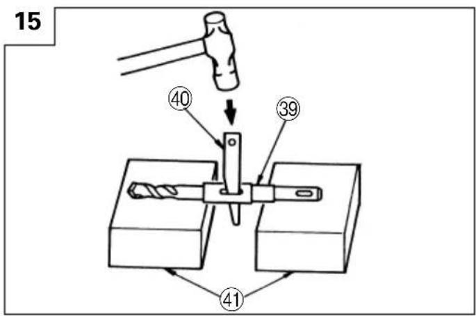
| 39 | Taper shank adapter | Kegelschaftadapter | Raccord de queue conique | Adattatore per gambo conico |
| 40 | Cotter | Dorn Clavette | Coppiglia | |
| 41 | Rest | Auflage Support | Appoggio | |
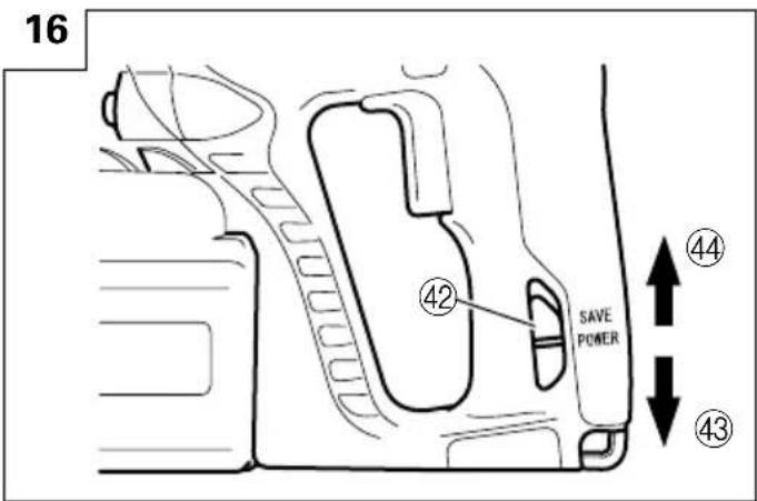
| 42 | Shift knob | Schaltknopf | Bouton de changement | Manopola del cambio |
| 43 | "POWER" mode | "POWER"-Modus | Mode "POWER" (puissance) | Modo "POWER" |
| 44 | "SAVE" mode | "SAVE"-Modus | Mode "SAVE" (économie) | Modo "SAVE" |
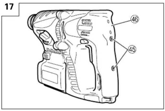
| 45 | Screw | Schraube | Vis | Vite |
| 46 | Grip cover | Griffabdeckung | Cache de saisie | Coperchio dell'impugnatura |
| 47 | Pull | Ziehen | Tirer | Tirare |
| 48 | Carbon brush | Kohlebürste | Balai en carbone | Spazzola di carbone |
| 49 | Terminal | Klemme Prise Terminale | ||
| 50 | Pliers | Zange | Pinces | Tenaglie |
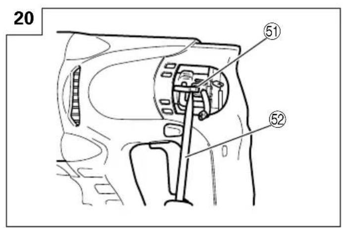
| 51 | Spring | Feder | Ressort | Molla |
| 52 | ⊖ driver | Flachschaubenzieher | Tournevis ⊖ | Cacciavite a ⊖ |
| 53 | Wear limit | Verschleißgrenze | Limite d'usure | Limite d'usura |
| Nederlands Español | Português Ελληνικά | |||
| 1 | Oplaadbare batterij Bateria | recargable Bateria recarregável | Επαναφορτιζόμενη μπαταρία | |
| 2 | Vergrendeling Enganche Lingüeta Måvõälo | |||
| 3 | Geleider batterij Riel de guía de la batería Guia da grade da bateria | Τροχιογραμμή της μπαταρίας | ||
| 4 | Drukken Presionar Apertar Σπρώξε | |||
| 5 | Behuizing Carcasa Cárter Περίβλημα | |||
| 6 | Uittrekken | Sacar | Retirar | Τραβήξτε έξω |
| 7 | Insteken | Insertar | Inserir | Εισχωρήστε |
| 8 | Geleiderail behuizing | Riel de guía de la carcasa | Trilho de segurança do cárter | Τροχιογραμμή του περιβλήματος |
| 9 | Kontrolelampje | Lámpara piloto | Lâmpada piloto | Δοκιμαστική λάμπα |
| 10 | Boorstuk | Broca | Broca | Λεπίδα τρυπανιού |
| 11 | Onderdeel van SDS Plus schacht | Parte del SDS más vástago | Cabo de peça SDS-plus | Τμήμα του SDS-plus στελέχους |
| 12 | Voorkap | Cubierta frontal | Tampa da frente | Μπροστινό περίβλημα |
| 13 | Greep Sujetador Mordente Λαβή | |||
| 14 | Stofvangkap | Copa de polvo | Receptáculo para poeira | Κύπελλο σκόνης |
| 15 | Stofverzamelaar (B) | Colector de polvo (B) | Coletor de poeira (B) | Συλλέκτης σκόνης (B) |
| 16 | Omstelknop | Perilla de cambio | Seletor | Μοχλός αλλαγής |
| 17 | “►”-markering | Marca “►” | Marca “►” | “►” σημάδι |
| 18 | “T”-markering | Marca “T” | Marca “T” | “T” σημάδι |
| 19 | “∞”-markering | Marca “∞” | Marca “∞” | “∞” σημάδι |
| 20 | “Draaien + Stoten” stand | Modo de “Rotación + Golpeteo” | Modo “Rotação + Martelada” | Τρόπος λειτουργίας “Περιστροφή + Κτύπημα” |
| 21 | “Alleen draaien” stand | Mode de “Rotación solamente” | Modo “Somente Rotação” | Τρόπος λειτουργίας “Περιστροφή μόνο” |
| 22 | Druktoets | Pulsador | Botão de pressão | Κουμπί ώθησης |
| 23 | Voorwaartse draairichting | Rotación hacia la derecha | Rotação para frente | Προς τα εμπρός περιστροφή |
| 24 | Terugwaartse draairichting | Rotación hacia la izquierda | Rotação inversa | Αντίστροφη περιστροφή |
| 25 | Draait niet | No gira | Nenhuma rotação | Δεν περιστρέφεται |
| 26 | Druk aan de (R) kant | Presione el lado (R) | Apertar o lado (R) | Σπρώξετε την (R) πλευρά |
| 27 | Druk aan de (L) kant | Presione el lado (L) | Apertar o lado (L) | Σπρώξετε την (L) πλευρά |
| 28 | Middenpositie | Posición central | Posição intermediária | Κεντρική θέση |
| 29 | (R) aanduiding | Indicación (R) | Indicação (R) | (R) ένδειξη |
| 30 | (L) aanduiding | Indicación (L) | Indicação (L) | (L) ένδειξη |
| 31 | Schema, gezien vanaf de handgreep-kant | Diagrama visto desde el lado del asa | Diagrama visto pelo lado do cabo | Διάγραμμα που βλέπεται από την πλευρά του χερουλιού |
| 32 | Boorkop | Portabrocas | Mandril | Σφικτήρας τρυπανιού |
| 33 | Boorkopadapter Adaptador del portabrocas Adaptador del portabrocas Adaptador del portabrocas Adaptador del portabrocas Adaptador del portabrocas Adaptador del portabrocas Adaptador del portabrocas Adaptador del portabrocas Adaptador del portabrocas Adaptador del portabrocas Adaptador del portabrocas Adaptador del portabrocas Adaptador del portabrocas Adaptador del portabrocas Adaptador del portabrocas AdaptADOR do mandril | Προσαρμογέας σφικτήρα Μετρητής βάθους | ||
| 34 | Diepte-maatlat | Calibre de profundidad | Sonda | |
| 35 | Montagegat | Agujero de montaje | Orifício de montagem | Τρύπα στερέωσης |
| 36 | Zijgreep | Mango lateral | Empunhadura lateral | Πλευρική λαβή |
| 37 | Boorstuk | Broca | Palhetão Λεπίδα | |
| 38 | Aansluithus | Cubo | Encaixe | Υποδοχή |
| 39 | Vernauwde schachtadaptor | Adaptador de la espiga | Adaptador de cabo cônico | Κωνικός προσαρμογέας στελέχους |
| 40 | Cotter Chaveta | Cavilha | Κόφτης | |
| 41 | Steun | Apoyo | Suporte | Στήριγμα |
| 42 | Schakelknop | Perilla de cambio | Seletor | Κουμπί αλλαγής |
| 43 | “POWER” stand | Modo “POWER” | Modo “POWER” | Θέση “POWER” |
| 44 | “SAVE” stand | Modo “SAVE” | Modo “SAVE” | Θέση “SAVE” |
| 45 | Schroef | Tornillo | Parafuso | Βίδα |
| 46 | Greepbekleding | Cubierta de la empuñadura | Proteção do cabo | Κάλυμμα λαβής |
| 47 | Pull | Ziehen | Puxar | Τραβήξετε |
| 48 | Koolborstel | Escobilla de carbón | Escova de carvão | Καρβουνάκια |
| 49 | Aansluiting | Terminal | Extremidade | Τερματικό |
| 50 | Tang | Alicates | Alicate | Λαβίδα |
| 51 | Veer | Resorte | Mola | Ελατήριο |
| 52 | Gewone ⊖ schroevendraaier | Destornillador de ⊖ | Chave de ⊖ | ⊖ οδηγός |
| 53 | SlijtagelimietSymbols⚠ WARNINGThe following show symbols used for the machine. Be sure that you understand their meaning before use. | Límite de desgasteSymbole⚠ WARNINGDie folgenden Symbole werden für diese Maschine verwendet. Achten Sie darauf, diese vor der Verwendung zu verstehen. | Limite de desgasteSymboles⚠ AVERTISSEMENTLes symboles suivants sont utilisés pour l’outil. Bien se familiariser avec leur signification avant d’utiliser l’outil. | Όριο φθοράςSimboli⚠ AVVERTENZADi seguito mostriamo i simboli usati per la macchina. Assicurarsi di comprenderne il significato prima dell’uso. |
 | Read all safety warnings and all instructions.Failure to follow the warnings and instructions may result in electric shock, fire and/or serious injury. | Lesen Sie sämtliche Sicherheitshinweise und Anweisungen durch.Wenn die Warnungen und Anweisungen nicht befolgt werden, kann es zu Stromschlag, Brand und/oder ernsthaftenVerletzungen kommen. | Lire tous les avertissements de sécurité et toutes les instructions.Tout manquement à observer ces avertissements et instructions peut engendrer des chocs électriques, des incendies et/ou des blessures graves. | Leggere tutti gli avvertimenti di sicurezza e tutte le istruzioni.La mancata osservanza degli avvertimenti e delle istruzioni potrebbe essere causa di scosse elettriche, incendi e/o gravi lesioni. |
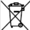 | Only for EU countriesDo not dispose of electric tools together with household waste material!In observance of European Directive 2002/96/EC on waste electrical and electronic equipment and its implementation in accordance with national law, electric tools that have reached the end of their life must be collected separately and returned to an environmentally compatible recycling facility. | Nur für EU-LänderWerfen Sie Elektrowerkzeuge nicht in den Hausmüll!Gemäss Europäischer Richtlinie 2002/96/EG über Elektro- und Elektronik-Altgeräte und Umsetzung in nationales Recht müssen verbrauchte Elektrowerkzeuge getrennt gesammelt und einer umweltgerechten Wiederververturnung zugeführt werden. | Pour les pays européens uniquementNe pas jeter les appareils électriques dans les ordures ménagères!Conformément à la directive européenne 2002/96/EG relative aux déchets d’équipements électriques ou électroniques (DEEE), et à sa transposition dans la législation nationale, les appareils électriques doivent être collectés à part et être soumis à un recyclage respectueux de l’environnement. | Solo per Paesi UENon gettare le apparecchiature elettriche tra i rifiuti domestici.Secondo la Direttiva Europea 2002/96/CE sui rifiuti di apparecchiature elettriche ed elettroniche e la sua attuazione in conformità alle norme nazionali, le apparecchiature elettriche esauste devono essere raccolte separatamente, al fine di essere reimpiegate in modo eco-compatibile. |
| Symbolen⚠ WAARSCHUWINGHieronder staan symbolen afgebeeld die van toepassing zijn op deze machine. U moet de betekenis hiervan begrijpen voor gebruik. | Símbolos⚠ ADVERTENCIAA continuación se muestran los símbolos usados para la máquina. Asegúrese de comprender su significado antes del uso. | Símbolos⚠ AVISOA seguir aparecem os símbolos utilizados pela máquina. Assimile bem seus significados antes do uso. | Σύμβολα⚠ ΠΡΟΣΟΧΗΤα παρακάτω δείχνουν τα σύμβολα που χρησιμοποιούνται στο μηχάνημα. Βεβαιωθείτε ότι κατανοείτε τη σημασίας τους πριν τη χρήση. | |
 | Lees alle waarschuwingen en instructies aandachtig door.Nalating om de waarschuwingen en instructies op te volgen kan in een elektrische schok, brand en/of ernstig letsel resulteren. | Lea todas las instrucciones y advertencias de seguridad.Si no se siguen las advertencias e instrucciones, podría producirse una descarga eléctrica, un incendio y/o daños graves. | Leia todas as instruções e avisos de segurança.Se não seguir todas as instruções e os avisos, pode provocar um choque eléctrico, incêndio e/ou ferimentos graves. | Διαθάζετε όλες τις προειδοποιήσεις ασφαλείας και όλες τις οδηγίες.Η μη τήρηση των προειδοποιήσεων και οδηγιών μπορεί να προκαλέσει ηλεκτροπληξία, πυρκαγιά καιή σοβαρό τραμματισμό. |
 | Alleen voor EU-landenGeef elektrisch gereedschap niet met het huisvuil mee!Volgens de Europese richtlijn 2002/96/EG inzake oude elektrische en elektronische apparaten en de toepassing daarvan binnen de nationale wetgeving, dient gebruikt elektrisch gereedschap gescheiden te worden ingezameld en te worden afgevoerd naar een recycle bedrijf dat voldoet aan de geldende milieu-eisen. | Sólo para países de la Unión Europea¡No deseche los aparatos eléctricos junto con los residuos domésticos!De conformidad con la Directiva Europea 2002/96/CE sobre residuos de aparatos eléctricos y electrónicos y su aplicación de acuerdo con la legislación nacional, las herramientas eléctricas cuya vida útil haya llegado a su fin se deberán recoger por separado y trasladar a una planta de reciclaje que cumpla con las exigencias ecológicas. | Apenas para países da UE Não deite ferramentas eléctricas no lixo doméstico!De acordo com a directiva europeia 2002/96/CE sobre ferramentas eléctricas e electrónicas usadas e a transposição para as leis nacionais, as ferramentas eléctricas usadas devem ser recolhidas em separado e encaminhadas a uma instalação de reciclagem dos materiais ecológica. | Μόνο για τις χώρες της ΕΕ Μην πετάτε τα ηλεκτρικά εργαλεία στον κάδο οικιακών απορριμμάτων!Σύμφωνα με την ευρωπαϊκή οδηγία 2002/96/EK περί ηλεκτρικών και ηλενσωμάτωσή της στο εθνικό δικαιο, τα ηλεκτρικά εργαλεία πρέπει να συλλέγονται ξεχωριστά και να επιστρέφονται για ανακύκλωση με τρόπο φιλικό προς το περιβάλλον. |
GENERAL POWER TOOL SAFETY WARNINGS

WARNING
Read all safety warnings and all instructions.
Failure to follow the warnings and instructions may result in electric shock, fire and/or serious injury.
Save all warnings and instructions for future reference.
The term "power tool" in the warnings refers to your mains-operated (corded) power tool or battery-operated (cordless) power tool.
1) Work area safety
a) Keep work area clean and well lit.
Cluttered or dark areas invite accidents.
b) Do not operate power tools in explosive atmospheres, such as in the presence of flammable liquids, gases or dust.
Power tools create sparks which may ignite the dust or fumes.
c) Keep children and bystanders away while operating a power tool.
Distractions can cause you to lose control.
2) Electrical safety
a) Power tool plugs must match the outlet.
Never modify the plug in any way.
Do not use any adapter plugs with earthed (grounded) power tools.
Unmodified plugs and matching outlets will reduce risk of electric shock.
b) Avoid body contact with earthed or grounded surfaces, such as pipes, radiators, ranges and refrigerators.
There is an increased risk of electric shock if your body is earthed or grounded.
c) Do not expose power tools to rain or wet conditions.
Water entering a power tool will increase the risk of electric shock.
d) Do not abuse the cord. Never use the cord for carrying, pulling or unplugging the power tool. Keep cord away from heat, oil, sharp edges or moving parts.
Damaged or entangled cords increase the risk of electric shock.
e) When operating a power tool outdoors, use an extension cord suitable for outdoor use.
Use of a cord suitable for outdoor use reduces the risk of electric shock.
f) If operating a power tool in a damp location is unavoidable, use a residual current device (RCD) protected supply.
Use of an RCD reduces the risk of electric shock.
3) Personal safety
a) Stay alert, watch what you are doing and use common sense when operating a power tool. Do not use a power tool while you are tired or under the influence of drugs, alcohol or medication. A moment of inattention while operating power tools may result in serious personal injury.
b) Use personal protective equipment. Always wear eye protection.
Protective equipment such as dust mask, non-skid safety shoes, hard hat, or hearing protection used for appropriate conditions will reduce personal injuries.
c) Prevent unintentional starting. Ensure the switch is in the off-position before connecting to power source and/or battery pack, picking up or carrying the tool.
Carrying power tools with your finger on the switch or energising power tools that have the switch on invites accidents.
d) Remove any adjusting key or wrench before turning the power tool on.
A wrench or a key left attached to a rotating part of the power tool may result in personal injury.
e) Do not overreach. Keep proper footing and balance at all times.
This enables better control of the power tool in unexpected situations.
f) Dress properly. Do not wear loose clothing or jewellery. Keep your hair, clothing and gloves away from moving parts.
Loose clothes, jewellery or long hair can be caught in moving parts.
g) If devices are provided for the connection of dust extraction and collection facilities, ensure these are connected and properly used.
Use of dust collection can reduce dust related hazards.
4) Power tool use and care
a) Do not force the power tool. Use the correct power tool for your application.
The correct power tool will do the job better and safer at the rate for which it was designed.
b) Do not use the power tool if the switch does not turn it on and off.
Any power tool that cannot be controlled with the switch is dangerous and must be repaired.
c) Disconnect the plug from the power source and/or the battery pack from the power tool before making any adjustments, changing accessories, or storing power tools.
Such preventive safety measures reduce the risk of starting the power tool accidentally.
d) Store idle power tools out of the reach of children and do not allow persons unfamiliar with the power tool or these instructions to operate the power tool.
Power tools are dangerous in the hands of untrained users.
e) Maintain power tools. Check for misalignment or binding of moving parts, breakage of parts and any other condition that may affect the power tools operation.
If damaged, have the power tool repaired before use.
Many accidents are caused by poorly maintained power tools.
f) Keep cutting tools sharp and clean.
Properly maintained cutting tools with sharp cutting edges are less likely to bind and are easier to control.
g) Use the power tool, accessories and tool bits etc. in accordance with these instructions, taking into account the working conditions and the work to be performed.
Use of the power tool for operations different from those intended could result in a hazardous situation.
5) Battery tool use and care
a) Recharge only with the charger specified by the manufacturer.
A charger that is suitable for one type of battery pack may create a risk of fire when used with another battery pack.
b) Use power tools only with specifically designated battery packs.
Use of any other battery packs may create a risk of injury and fire.
c) When battery pack is not in use, keep it away from other metal objects like paper clips, coins, keys, nails, screws, or other small metal objects that can make a connection from one terminal to another.
Shorting the battery terminals together may cause burns or a fire.
d) Under abusive conditions, liquid may be ejected from the battery; avoid contact. If contact accidentally occurs, flush with water. If liquid contacts eyes, additionally seek medical help.
Liquid ejected from the battery may cause irritation or burns.
6) Service
a) Have your power tool serviced by a qualified repair person using only identical replacement parts.
This will ensure that the safety of the power tool is maintained.
PRECAUTION
Keep children and infirm persons away.
When not in use, tools should be stored out of reach of children and infirm persons.
CORDLESS ROTARY HAMMER SAFETY WARNINGS
- Wear ear protectors
Exposure to noise can cause hearing loss.
- Use auxiliary handles supplied with the tool.
Loss of control can cause personal injury.
-
When drilling in wall, floor or ceiling, check for buried electric power cord, etc.
-
Do not touch the bit during or immediately after operation. The bit becomes very hot during operation and could cause serious burns.
-
Always hold the body handle and side handle of the power tool firmly. Otherwise the counterforce produced may result in inaccurate and even dangerous operation.
-
Always charge the battery at a temperature of 0 - 40°C.
A temperature of less than 0^ C will result in over charging which is dangerous. The battery cannot be charged at a temperature higher than 40^ C. The most suitable temperature for charging is that of 20 – 25^ C.
- Do not use the charger continuously.
When one charging is completed, leave the charger for about 15 minutes before the next charging of battery.
-
Do not allow foreign matter to enter the hole for connecting the rechargeable battery.
-
Never disassemble the rechargeable battery and charger.
-
Never short-circuit the rechargeable battery. Short-chircuiting the battery will cause a great electric current and overheat. It results in burn or damage to the battery.
-
Do not dispose of the battery in fire.
If the battery is burnt, it may explode.
-
When using this unit continuously, the unit may overheat, leading to damage in the motor and switch. Please leave it without using it for approximately 15 minutes.
-
Do not insert object into the air ventilation slots of the charger. Inserting metal objects or inflammables into the charger air ventilation slots will result in electrical shock hazard or damaged charger.
-
Using an exhausted battery will damage the charger.
-
Bring the battery to the shop from which it was purchased as soon as the post-charging battery life becomes too short for practical use. Do not dispose of the exhausted battery.
SPECIFICATIONS
POWER TOOL
| Model DH24DV | |||
| No-load speed Save/Power 0 - 500 min | -1/0 - 1000 min-1 | ||
| Full-load impact rate Save/Power 0 - 2200 min | -1/0 - 4500 min-1 | ||
| Capacity | Drilling | Concrete 24 mm | |
| Steel 13 mm | |||
| Wood 30 mm | |||
| Driving | Wood screw | 6.2 mm (diameter) × 40 mm (length) | |
| Rechargeable battery | EB2420: Ni-Cd 24 V (2.0 Ah 20 cells)EB2430HA: Ni-MH 24 V (3.0 Ah 20 cells)EB2433X: Ni-MH 24 V (3.3 Ah 20 cells) | ||
| Weight 4.0 kg | |||
☐ Do not use the "SAVE" mode when boring holes with the wood drill. There is a likelihood that the motor will burn out.
CHARGER
| Model UC24YFB | |
| Charging voltage 24 V | |
| Weight 0.6 kg |
STANDARD ACCESSORIES
| DH24DV (BFK)(HFK)(XFK) |    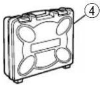 1 Side handle....12 Depth gauge....13 Charger....14 Plastic case....1 1 Side handle....12 Depth gauge....13 Charger....14 Plastic case....1 |
| DH24DV (2BFK)(2HFK)(2XFK) |   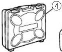  1 Side handle....12 Depth gauge....13 Charger....14 Plastic case....15 Extra battery....1 1 Side handle....12 Depth gauge....13 Charger....14 Plastic case....15 Extra battery....1 |
Standard accessories are subject to change without notice.
OPTIONAL ACCESSORIES (sold separately)
- Battery (EB2420, EB2430HA, EB2433X)

natural_image
Line drawing of a portable electronic device with no visible text or symbolsIt may be convenient to prepare some extra batteries.
- Drilling anchor holes (rotation + striking)
○Drill bit (taper shank) and taper shank adapter

Drill bit (taper shank)


Taper shank adapter (SDS plus shank)


Cotter
| Outer diameter |
| 11.0 mm |
| 12.3 mm |
| 12.7 mm |
| 14.3 mm |
| 14.5 mm |
| 17.5 mm |
| 21.5 mm |
| Taper mode Applicable drill bit | |
| Morse taper (No. 1) Drill bit (taper shank) 11.0 - 17.5 mm | |
| Morse taper (No. 2) Drill bit (taper shank) 21.5 mm | |
| A-taper | Taper shank adapter formed A-taper or B-taper is provided as an optional accessory, but drill bit for it is not provided. |
| B-taper | |
○13 mm Hammer Drill chuck and Chuck wrench

3. Anchor setting
○Anchor setting adapter (for rotary hammer)
| Anchor size |
| W1/4"W5/16"W3/8" |

Anchor setting adapter (for rotary hammer) (SDS plus shank)
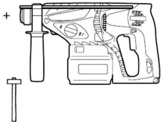
natural_image
Technical line drawing of a handgun assembly with labeled parts (no text or symbols)○Anchor setting adapter (for manual hammer)
| Anchor size |
| W1/4" |
| W5/16" |
| W3/8" |
| W1/2" |
| W5/8" |


4. Drilling holes and driving screws (rotation only)
○Drill chuck, chuck adapter (G) and chuck wrench


Special screw
Drill chuck (13VLR)
Chuck adapter (G) (SDS plus shank)

Chuck wrench

natural_image
Technical line drawing of a handgun with labeled parts (no text or symbols present)5. Drilling holes (rotation only)

☐ 13 mm drill chuck ass'y (include chuck wrench ass'y) and chuck (for drilling in steel or wood).
6. Driving Screws (rotation only)

| Bit No. Screw Size Length | |
| No. 2 3-5 mm 25 mm | |
| No. 3 5-8 mm 25 mm |
7. Dust cup, Dust collector (B)

Dust cup

Dust collector (B)
Optional accessories are subject to change without notice.
APPLICATIONS
Rotation and striking mode
○Drilling anchor holes
○Drilling holes in concrete
○Drilling holes in tile
Rotation only mode
○Drilling in steel or wood (with optional accessories)
○Tightening machine screws, wood screws (with optional accessories)
BATTERY REMOVAL/INSTALLATION
1. Battery removal
Hold the handle tightly and push the battery latches to remove the battery (see Figs. 1 and 2).
CAUTION:
Never short-circuit the battery.
2. Battery installation
Insert the battery aligning both guide rail of battery and body. Make sure the battery is fixed firmly.
CHARGING
Before using the power tool, charge the battery as follows.
-
Connect the charger's power cord to a receptacle. When the power cord is connected, the charger's pilot lamp will blink in red. (At 1-second intervals).
-
Insert the battery into the charger. Insert the battery into the charger as shown in Fig.
- Make sure the battery is fully seated in the charger.
3. Charging
When inserting a battery in the charger, charging will commence and the pilot lamp will light continuously in red. When the battery becomes fully recharged, the pilot lamp will blink in red. (At 1-second intervals.) (See Table 1)
(1) Pilot lamp indication The indications of the pilot lamp will be as shown in Table 1, according to the condition of the charger or the rechargeable battery.
Table 1
| Indications of the pilot lamp | |||
| Before charging | Blinks (RED) | Lights for 0.5 seconds. Does not light for 0.5 seconds. (off for 0.5 seconds) | |
| While charging | Lights (RED) | Lights continuously | |
| Charging complete | Blinks (RED) | Lights for 0.5 seconds. Does not light for 0.5 seconds. (off for 0.5 seconds) | |
| Charging impossible | Lights for 0.1 seconds. Does not light for 0.1 seconds. (off for 0.1 seconds) | Malfunction in the battery or the charger | |
| Charging impossible | Lights (GREEN) | Lights continuously | The battery temperature is high, making recharging impossible. |
(2) Regarding the temperatures of the rechargeable battery.
The temperatures for rechargeable batteries are as shown in the table 2, and batteries that have become hot should be cooled for a while before being recharged.
Table 2
| Battery type which the battery can be recharged | Temperatures at battery |
| EB2420 -5°C - 60°C | |
| EB2430HA, EB2433X 0°C | - 45°C |
(3) Regarding recharging time
Depending on the type of the battery, the charging time will become as shown in Table 3.
Table 3 Charging time (At 20°C)
| Battery type Re | charging time |
| EB2420 Approx. 50 | min. |
| EB2430HA Approx. | 70 min. |
| EB2433X Approx. 75 | min. |
NOTE: The charging time may vary according to ambient temperature and power source voltage.
-
Disconnect the charger's power cord from the receptacle.
-
Hold the charger firmly and pull out the battery. NOTE:
After operation, pull out batteries from the charger first, and then keep the batteries properly.
Regarding electric discharge in case of new batteries, etc.
As the internal chemical substance of new batteries and batteries that have not been used for an extended period is not activated, the electric discharge might be low when using them the first and second time. This is a temporary phenomenon, and normal time required for recharging will be restored by recharging the batteries 2–3 times.
How to make the batteries perform longer
(1) Recharge the batteries before they become completely exhausted.
When you feel that the power of the tool becomes weaker, stop using the tool and recharge its battery. If you continue to use the tool and exhaust the electric current, the battery may be damaged and its life will become shorter.
(2) Avoid recharging at high temperatures.
A rechargeable battery will be hot immediately after use. If such a battery is recharged immediately after use, its internal chemical substance will deteriorate, and the battery life will be shortened. Leave the battery and recharge it after it has cooled for a while.
CAUTION:
○If the battery has been heated right after operation (or due to sunlight, etc.), the charger's pilot lamp may not light in red. In such a case, first let the battery cool, then start charging.
When the pilot lamp flikers in red (at 0.2-second intervals), check for and take out any foreign objects in the charger's battery installation hole. If there are no foreign objects, it is probable that the battery or charger is malfunctioning. Take it to your authorized Service Center.
○Since the built-in micro computer takes about 3 seconds to confirm that the battery being charged with UC24YFB is taken out, wait for a minimum of 3 seconds before reinserting it to continue charging. If the battery is reinserted within 3 seconds, the battery may not be properly charged.
PRIOR TO OPERATION
1. Mounting the drill bit (Fig. 4, 5)
CAUTION:
To prevent accidents, make sure to turn the switch off.
NOTE:
When using tools such as drill bits, etc., make sure to use the genuine parts designated by our company.
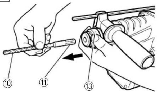
(1) Clean the shank portion of the drill bit.
(2) Insert the drill bit in a twisting manner into the tool holder until it latches itself. (Fig. 4)
(3) Check the latching by pulling on the drill bit.
(4) To remove the drill bit, fully pull the grip in the direction of the arrow and pull out the drill bit.
2. Confirm that the battery is mounted correctly.
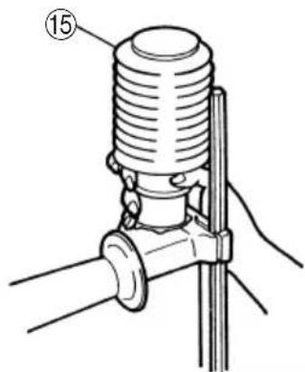
3. Installation of dust cup or dust collector (B) (Optional accessories) (Fig. 6, Fig. 7)
When using a rotary hammer for upward drilling operations attach a dust cup or a dust collector (B) to collect dust or particles for easy operation.
○Installing the dust cup
Use the dust cup by attaching to the drill bit as shown in Fig. 6.
When using a bit which has big diameter, enlarge the center hole of the dust cup with this rotary hammer.
○Installing dust collector (B)
When using dust collector (B), insert dust collector (B) from the tip of the bit by aligning it to the groove on the grip. (Fig. 7)
CAUTION:
○The dust cup and dust collector (B) are for exclusive use of concrete drilling work. Do not use them for wood or metal drilling work.
○Insert dust collector (B) completely into the chuck part of the main unit.
When turning the rotary hammer on while dust collector (B) is detached from a concrete surface, dust collector (B) will rotate together with the drill bit. Make sure to turn on the switch after pressing dust cup on the concrete surface. When using dust collector (B) attached to a drill bit that has more than 190 mm of overall length, dust collector (B) cannot touch the concrete surface and will rotate. Therefore, please use dust collector (B) by attaching to drill bits which have 166 mm, 160 mm, and 110 mm overall length.
○Dump particles after every two or three holes when drilling.
○Please replace the drill bit after removing dust collector (B).
4. Selecting the driver bit
Screw heads or bits will be damaged unless a bit appropriate for the screw diameter is employed to drive in the screws.
5. Confirm the direction of bit rotation (Fig. 9)
The bit rotates clockwise (viewed from the rear side) by pushing the R-side of the push button. (Fig. 9-a)
The L-side of the push button is pushed to turn the bit counterclockwise. (Fig. 9-b)
The motor does not rotate if the push button is set to the center position. (Fig. 9-c)
6. Continuous drilling
The number of holes that can be drilled in concrete after one recharge is shown in Table 4.
Table 4
| Bit dia. (mm) (mm) | Depth dri (mm) | Possible continuous ling number (holes) | ||
| EB2420 E | B2430HA EB | 2433X | ||
| 6.5 75 | 110 120 | |||
| 8.5 45 | 70 75 | |||
| 12.5 35 | 50 55 | |||
| 14.5 | 60 | |||
| 18 20 | 30 33 | 30 45 50 | ||
| 24 7 | 10 | 11 | ||
These data are for the referential values. The number of holes that can be drilled varies according to the sharpness of the used bit or the conditions of the concrete being drilled.
CAUTION:
When using this unit continuously, the unit may overheat, leading to damage in the motor and switch. Please leave it without using it for approximately 15 minutes.
HOW TO USE
1. Switch operation
○When the switch trigger is depressed, the tool rotates. When the switch trigger is released, the tool stops.
○The rotational speed of the rotary hammer can be controlled by varying the amount that the switch trigger is pulled. Speed is low when the switch trigger is pulled slightly and increases as the switch trigger is pulled more.
When releasing the switch trigger, the brake will be applied for immediate stopping.
2. Rotation + Striking
Align the “▶” mark with the “1T mark by rotating the change lever to set the “Rotation + Striking” mode. (Fig. 8)
(1) Mount the drill bit.
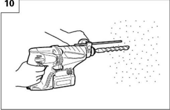
(2) Pull the trigger switch after applying the drill bit tip to the drilling position. (Fig. 10)
(3) Pushing the rotary hammer forcibly is not necessary at all. Pushing slightly so that drill dust comes out gradually is just sufficient.
CAUTION:
When the drill bit touches construction iron bar, the bit will stop immediately and the rotary hammer will react to revolve. Therefore please grip the side handle and handle tightly as shown in Fig. 10.
3. Rotation only
Align the “▶” mark with the “◀” mark by rotating the change lever to set the “Rotation only” mode. (Fig. 8)
To drill a wood or metal material using the optional drill chuck and chuck adapter, proceed as follows. Installing drill chuck and chuck adapter: (Fig. 11)
(1) Attach the drill chuck to the chuck adaptor.
(2) The part of the SDS-plus shank is the same as the drill bit. Therefore, refer to the item of "Mounting the drill bit" for attaching it.
CAUTION:
○Application of force more than necessary will not only expedite work at all, but will deteriorate the tip edge of the drill bit and reduce the service life of the rotary hammer in addition.
○Drill bit may snap off while withdrawing the rotary hammer from the drilled hole. For withdrawing, it is important to use a pushing motion.
○Do not attempt to use the rotary hammer in the rotation and striking mode with the drill chuck and chuck adapter attached. This would seriously shorten the service life of every component of the machine.
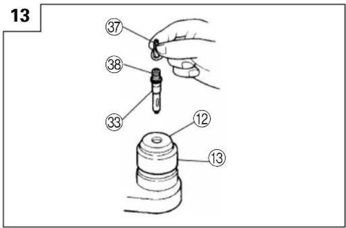
4. When driving wood screws (Fig. 13)
(1) Selecting a suitable driver bit Employ plus-head screws, if possible, since the driver bit easily slips off the heads of slotted-head screws.
(2) Tightening wood screws Prior to tightening wood screws, make pilot holes suitable for them in the wooden board. Apply the bit to the screw head grooves and gently drive the screws in the holes.
CAUTION:
Exercise care in preparing a pilot hole suitable for the wood screw taking the hardness of the wood into consideration. Should the hole be excessively small or shallow, requiring much power to drive the screw into it, the thread of the wood screw may sometimes be damaged.
5. Using depth gauge (Fig. 12)
(1) Loosen the knob on the side handle, and insert the depth gauge into the mounting hole on the side handle.
(2) Adjust the depth gauge position according to the depth of the hole and tighten the knob bolt securely.
6. How to use the drill bit (taper shank) and the taper shank adapter
(1) Mount the taper shank adapter to the rotary hammer. (Fig. 14)
(2) Mount the drill bit (taper shank) to the taper shank adapter. (Fig. 14)
(3) Turn the switch ON, and drill a hole to prescribed depth.
(4) To remove the drill bit (taper shank), insert the cotter into the slot of the taper shank adapter and strike the head of the cotter with a hammer supporting on the rest. (Fig. 15)
7. Switching between the "SAVE" and the "POWER" modes
The hammering force of the hammer can be increased or decreased to conform with intended usage, by operating the shift knob as per Fig. 16. Adjust the force to match the usage intended.
(1) "SAVE" mode ... decreased hammering force This can prevent thin drill bits which are less than 5 mm in diameter, from being bent or broken.
(2) "POWER" mode ... increased hammering force ○This can be used to speedily and efficiently drill holes when the drill bits which are being used are greater than 5 mm in diameter.
○This can be used to drill holes into wood or metal.
CAUTION:
Do not drill holes in wood with the "SAVE" mode. There is a likelihood that the motor will burn out because it can easily lock up due to the low power.
LUBRICATION
Low viscosity grease is applied to this rotary hammer so that it can be used for a long period without replacing the grease. Please contact the nearest service center for grease replacement when any grease is leaking form loosened screw.
Further use of the rotary hammer despite the grease shortage causes damage to reduce the service life.
CAUTION:
A specific grease (FG-6A) is used with this machine, therefore, the normal performance of the machine may be badly affected by use of different grease. Please be sure to let one of our service centers to undertake replacement of the grease.
MAINTENANCE AND INSPECTION
1. Inspecting the tool
Since use of a dull tool will degrade efficiency and cause possible motor malfunction, sharpen or replace the tool as soon as abrasion is noted.
2. Inspecting the mounting screws
Regularly inspect all mounting screws and ensure that they are properly tightened. Should any of the screws be loose, retighten them immediately. Failure to do so could result in serious hazard.
3. Maintenance of the motor
The motor unit winding is the very "heart" of the power tool. Exercise due care to ensure the winding does not become damaged and/or wet with oil or water.
4. Inspecting the carbon brushes (Fig. 21)
The Motor employs carbon brushes which are consumable parts. When they become worn to or near the "wear limit", it could result in motor trouble. When an auto-stop carbon brush is equipped, the motor will stop automatically. At that time, replace both carbon brushes with new ones which have the same carbon brush Numbers shown in the figure. In addition, always keep carbon brushes clean and ensure that they slide freely within the brush holders.
5. Replacing the carbon brushes
(1) Loosen the screws (2) for the chuck cover, then remove the chuck cover from the housing. (Fig. 17, Fig. 18)
(2) Pinch the terminals for the carbon brushes with pliers, then pull them out of the brush holder. (Fig. 19)
(3) Pull the springs forward with a Phillips screwdriver, then remove the carbon brushes. (Fig. 20)
(4) Reverse these procedures to install the brushes.
6. Cleaning on the outside
When the power tool is stained, wipe with a soft dry cloth or a cloth moistened with soapy water. Do not use chloric solvents, gasoline or paint thinner, as they melt plastics.
7. Storage
Store the power tool in a place in which the temperature is less than 40^ C and out of reach of children.
8. Service parts list
A: Item No.
B: Code No.
C: No. Used
D: Remarks
CAUTION:
Repair, modification and inspection of Hitachi Power Tools must be carried out by an Hitachi Authorized Service Center.
This Parts List will be helpful if presented with the tool to the Hitachi Authorized Service Center when requesting repair or other maintenance.
In the operation and maintenance of power tools, the safety regulations and standards prescribed in each country must be observed.
MODIFICATIONS:
Hitachi Power Tools are constantly being improved and modified to incorporate the latest technological advancements.
Accordingly, some parts (i.e. code numbers and/or design) may be changed without prior notice.
GUARANTEE
We guarantee Hitachi Power Tools in accordance with statutory/country specific regulation. This guarantee does not cover defects or damage due to misuse, abuse, or normal wear and tear. In case of complaint, please send the Power Tool, undismantled, with the GUARANTEE CERTIFICATE found at the end of this Handling instruction, to a Hitachi Authorized Service Center.
NOTE:
Due to HITACHI's continuing program of research and development, the specifications herein are subject to change without prior notice.
Information concerning airborne noise and vibration
The measured values were determined according to EN60745 and declared in accordance with ISO 4871.
Measured A-weighted sound power level: 103 dB (A). Measured A-weighted sound pressure level: 92 dB (A). Uncertainty KpA: 3 dB (A).
Wear ear protection.
Vibration total values (triax vector sum) determined according to EN60745.
Hammer drilling into concrete:
Vibration emission value ah,HD=10.2m/s^2
Uncertainty K = 1.5 m/s ^4
WARNING
○The vibration emission value during actual use of the power tool can differ from the declared value depending on the ways in which the tool is used.
To identify the safety measures to protect the operator that are based on an estimation of exposure in the actual conditions of use (taking account of all parts of the operating cycle such as the times when the tool is switched off and when it is running idle in addition to the trigger time).
natural_image
Line drawing of a mechanical device with no visible text or symbolsnatural_image
Technical line drawing of a handgun with internal components and a battery (no text or symbols)
Bohrfutterschlüssel
3. Ankereinsatz
| Ankergröße |
| W1/4"W5/16"W3/8" |

| Ankergröße |
| W1/4" |
| W5/16" |
| W3/8" |
| W1/2" |
| W5/8" |


natural_image
Technical line drawing of a hand tool with labeled parts and a plus sign (no readable text or symbols)natural_image
Technical line drawing of a handgun with internal components and no visible text or symbolsnatural_image
Line drawing of a handgun with internal components and no visible text or symbolsnatural_image
Line drawing of a mechanical device casing (no text or symbols)natural_image
Technical line drawing of a handgun with internal components and a handle (no text or symbols)| Dimension de l'ancrage |
| W1/4" |
| W5/16" |
| W3/8" |
| W1/2" |
| W5/8" |

natural_image
Technical line drawing of a handgun with labeled parts (no text or symbols present)
natural_image
Technical line drawing of a handgun with labeled parts (no text or symbols present)| No. de mèche | Dimension de vis Longueur |
| No. 2 3-5 | mm 25 mm |
| No. 3 5-8 | mm 25 mm |
natural_image
Line drawing of a mechanical device casing (no text or symbols)| Diametro esterno |
| 11,0 mm |
| 12,3 mm |
| 12,7 mm |
| 14,3 mm |
| 14,5 mm |
| 17,5 mm |
| 21,5 mm |
natural_image
Technical line drawing of a handgun with labeled parts (no readable text or symbols)natural_image
Technical line drawing of a handgun with internal components and no visible text or symbols
Chiave per mandrino
natural_image
Technical line drawing of a handgun with internal components and a battery (no text or symbols)| Punta in. Dimensioni vite Lunghezza | |
| No. 2 3-5 mm 25 mm | |
| No. 3 5-8 mm 25 mm | |
7. Contenitore a polvere, Camera a polvere (B)
natural_image
Line drawing of a mechanical device with no visible text or symbolsnatural_image
Technical line drawing of a handgun with internal components and no visible text or symbols
Cotter
| Buitendiameter |
| 11,0 mm |
| 12,3 mm |
| 12,7 mm |
| 14,3 mm |
| 14,5 mm |
| 17,5 mm |
| 21,5 mm |
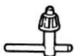
Sleutel
| Anker formaat |
| W1/4"W5/16"W3/8" |

Ankerstellingsadapter (voor electrische boorhamer) (SDS Plus schacht)


○Ankerstellingsadapter (voor normale hamer)
| Anker formaat |
| W1/4" |
| W5/16" |
| W3/8" |
| W1/2" |
| W5/8" |


natural_image
Technical line drawing of a handgun with internal components and no visible text or symbolsnatural_image
Technical line drawing of a handgun with labeled parts (no text or symbols present)| Boorstuk Nr. Schroefmaat Lengte | |
| Nr. 2 3-5 mm 25 mm | |
| Nr. 3 5-8 mm 25 mm | |
7. Stofvangkap, Stofverzamelaar (B)

Stofvangkap

Stofverzamelaar (B)
natural_image
Line drawing of a mechanical device casing (no text or symbols)natural_image
Technical line drawing of a handgun with labeled parts (no text or symbols)natural_image
Technical line drawing of a handgun with internal components and adjustment knobs (no text or symbols)7. Copa de polvo, Colector de polvo (B)

Copa de plovo

Colector de polvo (B)
natural_image
Line drawing of a mechanical device casing (no text or symbols)natural_image
Technical line drawing of a handgun with labeled parts (no text or symbols present)| Diâmetro externo |
| 11,0 mm |
| 12,3 mm |
| 12,7 mm |
| 14,3 mm |
| 14,5 mm |
| 17,5 mm |
| 21,5 mm |
natural_image
Technical line drawing of a handgun with internal components and adjustment knobs (no text or symbols)
Chave de mandril
| Tamanho da âncora |
| W1/4" |
| W5/16" |
| W3/8" |
| W1/2" |
| W5/8" |

natural_image
Technical line drawing of a handgun with internal components and no visible text or symbolsnatural_image
Line drawing of a handgun with labeled parts (no text or symbols present)
Chave de mandril
natural_image
Line drawing of a handgun with internal components and no visible text or symbolsnatural_image
Line drawing of a mechanical device casing (no text or symbols)natural_image
Technical line drawing of a handgun with internal components and no visible text or symbols
Κόφτης
natural_image
Technical line drawing of a handgun with internal components and no visible text or symbols
Κλειδί σφικτήρα
natural_image
Technical line drawing of a handgun assembly (no text or labels)natural_image
Technical line drawing of a handgun with labeled parts (no text or symbols present)
natural_image
Line drawing of a quill pen in an inkwell (no text or symbols)| English | Nederlands | ||
| GUARANTEE CERTIFICATE1Model No.2Serial No.3Date of Purchase4Customer Name and Address5Dealer Name and Address(Please stamp dealer name and address) | GARANTIEBEWIJS1Modelnummer2Serienummer3Datum van aankoop4Naam en adres van de gebruiker5Naam en adres van de handelaar(Stempel a.u.b. naam en adres vande de handelaar) | ||
| Deutsch | Español | ||
| GARANTIESCHEIN1Modell-Nr.2Serien-Nr.3Kaufdaturn4Name und Anschrift des Kunden5Name und Anschrift des Händlers(Bitte mit Namen und Anschrift des Handlers abstempeln) | CERTIFICADO DE GARANTIA1Número de modelo2Número de serie3Fecha de adquisición4Nombre y dirección del cliente5Nombre y dirección del distribudor(Se ruega poner el sellú del distribudor con su nombre y dirección) | ||
| Français Português | |||
| CERTIFICAT DE GARANTIE1No. de modèle2No. de série3Date d'achat4Nom et adresse du client5Nom et adresse du revendeur(Cachet portant le nom et l'adresse du revendeur) | CERTIFICADO DE GARANTIA1Número do modelo2Número do série3Data de compra4Nome e morada do cliente5Nome e morada do distribuidor(Por favor, carímbe o nome e morada do distribuidor) | ||
| Italiano Ελληνικά | |||
| CERTIFICATO DI GARANZIA1Modello2N° di serie3Data di acquisto4Nome e indirizzo dell'acquirente5Nome e indirizzo del rivenditore(Si prega di apporre il timbro con questi dati) | ΠΙΣΤΟΠΟΙΗΤΙΚΟ ΕΓΓΥΗΣΗΣ1Ap. Movτέλου2Αύξων Ap.3Ημερομηνία αγοράς4Όνομα και διεύθυνση πελάτη5Όνομα και διεύθυνση μεταπωλητή(Παρακαλούμε να χρησιμοποιηθεί σφραγίδα) | ||
HITACHI
| 1 | |
| 2 | |
| 3 | |
| 4 | |
| 5 |
Hitachi Power Tools Europe GmbH
Siemensring 34, 47877 willich 1, F. R. Germany
Tel: +49 2154 49930
Fax: +49 2154 499350
URL: http://www.hitachi-powertools.de
Hitachi Power Tools Netherlands B. V.
Brabanthaven 11, 3433 PJ Nieuwegein, The Netherlands
Tel: +31 30 6084040
Fax: +31 30 6067266
URL: http://www.hitachi-powertools.nl
Hitachi Power Tools (U. K.) Ltd.
Precedent Drive, Rooksley, Milton Keynes, MK 13, 8PJ, United Kingdom
Tel: +44 1908 660663
Fax: +44 1908 606642
URL: http://www.hitachi-powertools.co.uk
Hitachi Power Tools France S. A. S.
Prac del' Eglantier 22, rue des Crerisiers Lisses, C. E. 1541,
91015 EVRY CEDEX, France
Tel: +33 1 69474949
Fax: +33 1 60861416
URL: http://www.hitachi-powertools.fr
Hitachi Power Tools Belgium N.V. / S.A.
Koningin Astridlaan 51, 1780 Wemmel, Belgium
Tel: +32 2 460 1720
Fax: +32 2 460 2542
URL http://www.hitachi-powertools.be
Hitachi Fercad Power Tools Italia S.p.A
Via Retrone 49-36077, Altavilla Vicentina (VI), Italy
Tel: +39 0444 548111
Fax: +39 0444 548110
URL: http://www.hitachi-powertools.it
Hitachi Power Tools Iberica, S.A.
C / Migjorn, s/n, Poligono Norte, 08226 Terrassa, Barcelona, Spain
Tel: +34 93 735 6722
Fax: +34 93 735 7442
URL: http://www.hitachi-powertools.es
- GENERAL POWER TOOL SAFETY WARNINGS
- WARNING
- Save all warnings and instructions for future reference.
- 1) Work area safety
- 2) Electrical safety
- 3) Personal safety
- 4) Power tool use and care
- 5) Battery tool use and care
- 6) Service
- PRECAUTION
- CORDLESS ROTARY HAMMER SAFETY WARNINGS
- SPECIFICATIONS
- OPTIONAL ACCESSORIES (sold separately)
- Anchor setting
- Drilling holes and driving screws (rotation only)
- Drilling holes (rotation only)
- Driving Screws (rotation only)
- Dust cup, Dust collector (B)
- APPLICATIONS
- BATTERY REMOVAL/INSTALLATION
- Battery removal
- CAUTION:
- Battery installation
- CHARGING
- Charging
- How to make the batteries perform longer
- PRIOR TO OPERATION
- Mounting the drill bit (Fig. 4, 5)
- NOTE:
- Confirm that the battery is mounted correctly.
- Installation of dust cup or dust collector (B) (Optional accessories) (Fig. 6, Fig. 7)
- Selecting the driver bit
- Confirm the direction of bit rotation (Fig. 9)
- Continuous drilling
- HOW TO USE
- Switch operation
- Rotation + Striking
- Rotation only
- When driving wood screws (Fig. 13)
- Using depth gauge (Fig. 12)
- How to use the drill bit (taper shank) and the taper shank adapter
- Switching between the "SAVE" and the "POWER" modes
- LUBRICATION
- MAINTENANCE AND INSPECTION
- Inspecting the tool
- Inspecting the mounting screws
- Maintenance of the motor
- Inspecting the carbon brushes (Fig. 21)
- Replacing the carbon brushes
- Cleaning on the outside
- Storage
- Service parts list
- MODIFICATIONS:
- GUARANTEE
- Information concerning airborne noise and vibration
- Ankereinsatz
- Contenitore a polvere, Camera a polvere (B)
- Stofvangkap, Stofverzamelaar (B)
- Copa de polvo, Colector de polvo (B)
- HITACHI
- Hitachi Power Tools Europe GmbH
- Hitachi Power Tools Netherlands B. V.
- Hitachi Power Tools (U. K.) Ltd.
- Hitachi Power Tools France S. A. S.
- Hitachi Power Tools Belgium N.V. / S.A.
- Hitachi Fercad Power Tools Italia S.p.A
- Hitachi Power Tools Iberica, S.A.
Brand : HITACHI
Model : DH 24DV
Category : Drill