ZI-HDR200 - Pressure washer Zipper - Free user manual and instructions
Find the device manual for free ZI-HDR200 Zipper in PDF.

User questions about ZI-HDR200 Zipper
0 question about this device. Answer the ones you know or ask your own.
Ask a new question about this device
Download the instructions for your Pressure washer in PDF format for free! Find your manual ZI-HDR200 - Zipper and take your electronic device back in hand. On this page are published all the documents necessary for the use of your device. ZI-HDR200 by Zipper.
USER MANUAL ZI-HDR200 Zipper
natural_image
Green stylized letter 'Z' on black background, no text or symbols presentGartengeräte
Z.I.P.P.E.R Maschinen GmbH. GEWERBEPARK SCHLUSSLBERG 8 AT-4710 GRIESKIRCHEN TEL.: +43 (0) 7248 61116 702 (SERVICE) FAX.: +43 (0) 7248 61116 721 INFO@ZIPPER-MASCHINEN.AT HTTP://WWW.ZIPPER-MASCHINEN.AT
High pressure cleaner
CE


natural_image
Green and black ZIPPER 400001 water heater with coiled hose and control panel (no visible text or symbols on body)ZI-HDR200 / ZI-HDR230
EAN:9120039238197/9120039238210
EN Read the operation manual carefully before first use.
ES
FR

text_image
Z I P P E R

ATTENTION! Ignoring the safety signs and warnings applied on the machine as well as ignoring the security and operating instructions can cause serious injuries and even lead to death.


READ THE MANUAL! Read the user and maintenance manual carefully and get familiar with the controls n order to use the machine correctly and to avoid injuries and machine defects.


PROTECTIVE CLOTHING! The operator is obligated to wear proper ear protection, safety goggles and safety shoes


CE-KONFORM! - Dieses Produkt entspricht den EG-Richtlinien. CE-Conformal! - This product complies with the EC-directives.
Fig. A

text_image
Technical diagram of a water heater with numbered parts and labeled partsFig. B
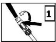
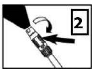
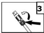
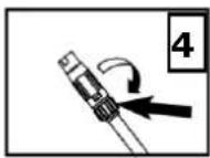

Fig. C
natural_image
Technical line drawing of a mechanical assembly (no text or symbols)Fig. D
natural_image
Diagram of a mechanical device with directional arrows indicating motion (no text or symbols)Fig. E
natural_image
Line drawing of a handheld device with an arrow pointing to the handle (no text or symbols)Fig. F

text_image
Nozzle Tip Cleaner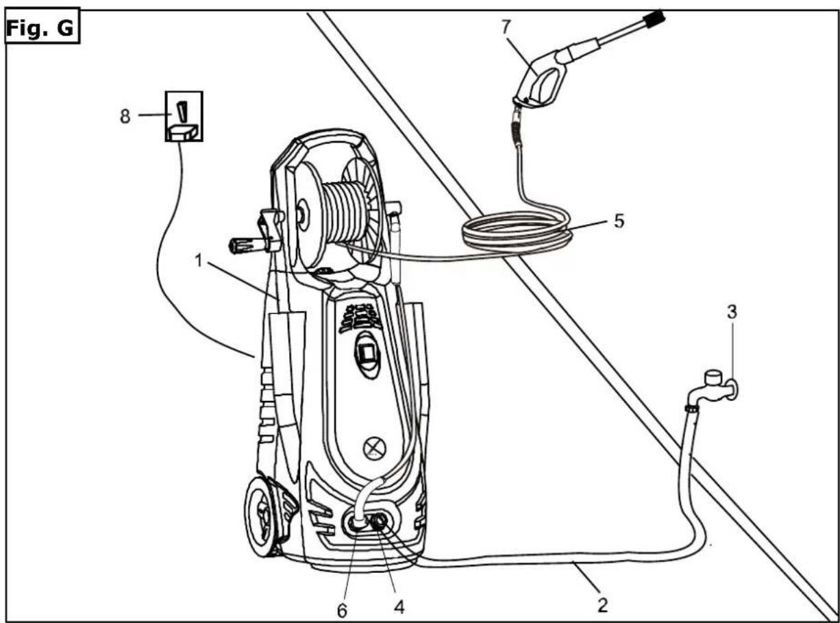
text_image
Fig. G 1 2 3 4 5 6 7 81 D
BEDIENUNGSANLEITUNG
text_image
Technical diagram of a mechanical assembly with numbered parts, likely an engine or motor assembly.| Pos. | Name | Pcs. |
| 1 | Wasserausfluss | 1 |
| 2 | O-Ring 22x2 4mm | 1 |
| 3 | Feder 6x10.5x4.5x12 | 1 |
| 4 | Kappenventil | 1 |
| 5 | O-Ring, 5x1.8mm | 1 |
| 6 | Ventil | 1 |
| 7 | Federventil | 1 |
| 8 | Kappenventil | 1 |
| 8A | O-Ring, 4.5x.1.8mm | 1 |
| 9 | O-Ring, 16x2.4mm | 1 |
| 10 | Kolben | 1 |
| 11 | Kolbenfeder | 1 |
| 12 | Federteller | 1 |
| 13 | O-Ring, 5x1.8mm | 1 |
| 13A | Seat, valve | 1 |
| 13B | O-ring, 12x1.8mm | 1 |
| 14 | Pump head | 1 |
| 15 | Screw M8x20 | 4 |
| 16 | O-Ring 18x2.4mm | 1 |
| 17 | Einfluss-Anschluss | 1 |
| 18 | Filter | 1 |
| 19 | Anschlussblock Sicherungsring | 1 |
| 20 | Y-Ring | 1 |
| 21 | Schalterabdeckung | 1 |
| 22 | O-Ring, 22x2.4mm | 1 |
| 23 | Anschluss | 1 |
| 24 | Schalter | 1 |
| 25 | Bogen | 1 |
| 26 | Feder, 1x7.8x 9x19 | 1 |
| 27 | Microschalter | 1 |
| 28 | Pumpkörper | 1 |
| 29 | Unterer Schutz | 1 |
This manual contains important information and advice for the correct and safe use and maintenance of the ZIPPER high pressure cleaner. The manual is part of the machine and may not be stored separately. Read it profoundly before first use of the machine and keep it for later reference. When the machine is handed to other persons always put the manual to the machine.
Please follow the security instructions!
Due to continuous development of our products illustrations, pictures might differ slightly.
Attention!
Technical changes reserved!
Copyright
© 2010
This manual is protected by copyright law – all rights reserved. Especially the reprinting as well as the translation and depiction of pictures will be prosecuted by law. Court of jurisdiction is WELS, Austria.
Customer Support
The operation manual is part of the machine and the customer must read it before the first use. When the machine is given to another person you must also give him this manual.
2.1 Components (Fig. A)
| 1 | High pressure washer |
| 2 | On/off switch |
| 3 | Mobile adapter bracket with wheel |
| 4 | Water outlet |
| 5 | Water inlet |
| 6 | Gun |
| 7 | Hose Reel with Trigger Gun Hose |
| 8 | Hose Reel Handle |
2.1.1 Delivery contents
Unpack the ZIPPER high pressure cleaner ZI-HDR200 / ZI-HDR230 and control whether it is in a perfect condition and whether all the parts are included in delivery.
2.1.2 Technical Details
| ZI-HDR200 | ZI-HDR230 | |
| Working pressure | 130 bar | 150 bar |
| Allowable pressure | 195 bar | 225 bar |
| Working flow rate | 7 l/min | 7 l/min |
| Max flow rate | 8.7 l/min | 8.7 l/min |
| Max. pressure water supply | 0.4MPa(4bar) | 0.4MPa(4bar) |
| Motor Capacity | 2.5kw | 3.0kw |
| Power Supply Voltage | 230V~50Hz | 230V~50Hz |
| LPA(sound pressure) | 79dB | 76dB |
| LWA(acoustic power) | 97 dB(A) | 94 dB(A) |
| Vibration value | 2.5m/s2 | 2.5m/s2 |
| Max Water Temperature | 50 | 50 |
| Weight | 22kg | 24kg |
| Dimensions | 88x 36.5 x38cm | 88x 36.5 x38cm |
Technical changes reserved.
2.2 SAFETY
2.2.1 Intended usage
The ZIPPER high pressure cleaners ZI-HDR200 and ZI-HDR230 are only admitted for the following works at observance of the safety-, operation- and maintenance instructions:
- Trench tamping
- Clean cars
- Bikes
- Outdoor equipment
- Garden patios
- Green houses etc.

IMPORTANT
Do not operate the engine at maximum speed right from the start, as the engine itself as well as the gear-ing components need a running-in time. The engine itself reaches its maximum capacity after the first 10 hours of operation. Non-compliance with this instruction reduces your engine lifespan substantially.
When you don't take care of the intended usage and at non-compliance of the instructions in this manual you will lose all the compensation demands from the ZIPPER GmbH.
Changes and manipulations on the machine also lead to the expire of the guarantee and compensation demands.

Always be focused when working, take care to maintain a safe posture at every time.

2.3 Helpful Hints for Getting Started
2.3.1 Automatic ON/OFF:
The motor on this pressure washer does not run continuously. It only runs when the trigger of the spray gun is squeezed. After following the start up procedures in this manual, turn the pressure washer ON and squeeze the trigger for activation. See the section of this manual entitled "Operating Instructions" for further details on this feature.
2.3.2 Bleeding the Gun:
It is very important to bleed the gun before using the pressure washer. Squeeze the trigger to allow any air that is trapped inside of the unit and hose to escape. Continue to squeeze trigger until a steady stream of water comes from the nozzle. (This process may take up to 2 minutes). See the section of this manual entitled "Operating Instructions" for further details on this process.
2.4 SAFETY REGULATIONS

- This machine is not intended for use by persons (including children) with reduced physical, sensory or mental capabilities, or lack of experience and knowledge, unless they have been given supervision or instruction concerning use of the machine by a person responsible for their safety.
• Children should be supervised to ensure that they do not play with the machine. - The electrical supply connection shall be made by a qualified person and comply with IEC 60364-1. The electric supply to this machine should include either a residual current device that will interrupt the supply if the leakage current to earth exceeds 30 mA for 30 ms or a device that will prove the earth circuit.
- The machine is intended to be used at a temperature above 0 degree. (Only for machine with power cord of H05VV-F).
- This machine has been designed for use with the cleaning agent supplied or recommended by the manufacturer. The use of other cleaning agents or chemicals may adversely affect the safety of the machine.
- High pressure jets can be dangerous if subject to misuse. The jet must not be directed at persons, live electrical equipment or the machine itself.
- Recommend the operator to wear ear protectors.
- Do not use the machine within range of persons unless they wear protective clothing.
- Do not direct the jet against yourself or others in order to clean clothes or foot-wear.
- Risk of explosion-Do not spray flammable liquids.
• High pressure cleaners shall not be used by children or untrained personnel. - High pressure hoses, fittings and couplings are important for the safety of the machine. Use only hosed, fittings and couplings recommended by the manufacturer.
- To ensure machine safety, use only original spare parts from the manufacturer or approved by the manufacturer.
• Water that has flown through backflow preventers is considered to the non-potable. - The machine shall be disconnected from its power source by removing the plug from the socket-outlet during cleaning or maintenance and when replacing the machine to another function.
- Do not use the machine if a supply cord or important parts of the machine are damaged, e.g. safety devices, high pressure hoses, trigger gun.
- If an extension cord is used, the plug and socket must be of watertight construction.

- Inadequate extension cords can be dangerous.
- Warning symbol: Machine not suitable for connection to the potable water mains.
- The machine is not intended to be connected to the potable water mains.
- To ensure the machine safety, please only use original spare parts (including nozzle) from the manufacturer or approved by the manufacturer. Do not use the machine before you changed them if they are damaged.
- Be care of the danger of the kickback force on the spray assembly when opening the trigger gun and grasp the gun with hands firmly.
- Read all the instructions before using the machine.
- Know how to stop the machine and bleed pressures quickly. Be thoroughly familiar with the controls.
- Stay alert and watch what you are doing.
- Do not operate the machine when fatigued or under the influence of alcohol or drugs.
- Keep operating area clear of all persons.
- Do not overreach or stand on unstable support. Keep good footing and balance at all times.
- Follow the maintenance instructions specified in the manual.
- This machine must be grounded. If it has malfunction or breakdown, grounding provides a path of least resistance for electric current to reduce the risk of electric shock. The plug must be plugged into an appropriate outlet that is properly installed and grounded in accordance with all local codes and ordinances. The rating voltage (V/Hz) of the machine has to be in compliance with the local p supplying voltage.
- Check with a qualified electrician or service personnel if you are in doubt as to whether the outlet is properly grounded. Do not modify the plug provided with the machine. If it will not fit the outlet, have a proper outlet installed by a qualified electrician. Do not use any type of adapter with this machine.
- Use only 3-wire extension cords that have 3-prong grounding-type plugs and 3-pole cord connectors that accept the plug from the machine. Use only extension cords that are intended for outdoor use and the socket must be of watertight construction. These extension cords are identified by a marking "Acceptable for use with outdoor machines; store indoors while not in use." Use only extension cords having an electrical rating not less than the rating of the machine. Do not use damaged exter cords. Examine extension cord before using and replace if damaged. Inadequate extension cords can be dangerous. Do not abuse extension cord and do not yank on any cord to disconnect. Keep cord away from heat and sharp edges. Always disconnect the extension cord from the receptacle be disconnecting the machine from the extension cord.

- To reduce the risk of electrocution, don't start and run the machine in the rain or storm. Keep all connections dry and off the ground. Do not touch plug with wet hands. It is strictly prohibited to let water leak into the machine.
- When the machine is running, please maintain a constant water supply. Without water circulation will damage the sealing rings of the machine.
- It is necessary to turn on the spray lance within one or two minutes after the machine has been started. Otherwise, the temperature of the circulating water within the machine will soon rise to a critical point, which will cause damage to the sealing rings inside the machine.
- Don't start and run the machine in a place excessively cold so as to prevent the machine from the freezing current.
• This machine has been designed for only using cleaning water, do not use corrosive chemicals. - Disconnect from the electrical power supply before carrying out user maintenance.
- Make sure the inlet water pressure keeps between 0.01MPa and 0.4MPa. The inlet pipe should at least 5 M long. Do not use the pipe if the pipe is damaged. If you want connect this machine to portable water mains, you must install a backflow preventer in the water pipe to prevent dirty water flow back to the drinking water system. The backflow preventer shall comply with.
2.5 Operation instructions
2.5.1 Workings before starting up
- Reading, understanding and obeying the safety instructions.
- Unpacking all the parts. Controlling the machine on dust and other dirt.
- This unit is to be connected to a cold water source ONLY
- The motor of this pressure washer will NOT run. It will only operate when the trigger is squeezed.
- Connect the outlet hose to the washer and connect the spray gun to the outlet hose.
- Connect nozzle and nozzle extension.
- Check gauze filter is clear of any blockage.
- Connect the water supply hose.
- Check that the hose has no kinks in it.
- Turn on water and check for leaks.
- Depress trigger to allow air to be expelled though the pump and hoses, lock trigger.
- Plug in machine and turn on switch.
- Unlock trigger and use the pressure washer.
2.5.2 Shut down
- Turn off the motor(push switch to the off position)
- Unplug the unit from the power source.
- Turn off the water supply.
- Press the trigger of the gun to depressurize the system.
- Disconnect the garden hose from the pressure washer.
- Wipe all surfaces of the unit with a damp clean cloth.


CAUTION
ALWAYS turn off the unit's motor BEFORE turning off the unit's water supply.
Serious damage could occur to the motor if the unit is run without water.


CAUTION
NEVER disconnect the high-pressure discharge
Hose from the machine while the system is still pressurized. To depressurize the unit, turn off the motor, turn off the water supply and squeeze the trigger 2-3 times.
2.5.3 ADJUSTABLE SPRAY NOZZLE
Turn off the spray lance first, hold the rear part of spray nozzle, then turn the front part of spray nozzle clockwise, Water may be sprayed out from the spray nozzle in fan shapes (pic. 1 Fig. B); Turn the front part of spray nozzle with- ershins, Water may be sprayed out from the spray nozzle linearly (pic 2 on Fig. B).
on


CAUTION
Water should be sprayed out from the spray nozzle in fan shapes (pic 2 or Fig. B), when cleaning the car or other vehicle.
2.5.4 Low/High Pressure Adjustable Lance
2.5.4.1. Using High Pressure:
Please make sure the trigger released and there is not any water spraying. Then turn the rear part of spray nozzle withershins (pic 4 on Fig. B). Squeeze the trigger, the gun will spray water with high pressure.
2.5.4.2. Using low pressure:
Please make sure the trigger released and there is not any water spraying. then turn the rear part of spray nozzle clockwise (pic 3 on Fig. B). Squeeze the trigger, the gun will spray water with low pressure.


CAUTI ON
Selection of high or low pressure by turning action. The selection of the pressure must be carried out with the gun in closed position.
2.5.5 WATER INLET SCREEN
The water inlet filter must be inspected regularly, so as to avoid blockage and restriction in the water supply to the pump (pic 5 on Fig. B).
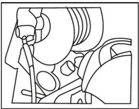
2.5.6 USING DETERGENT
Add detergent to the container. Set the Adjustable Spray Wand at low pressure position. (fig C) Trigger gun to spray detergent.
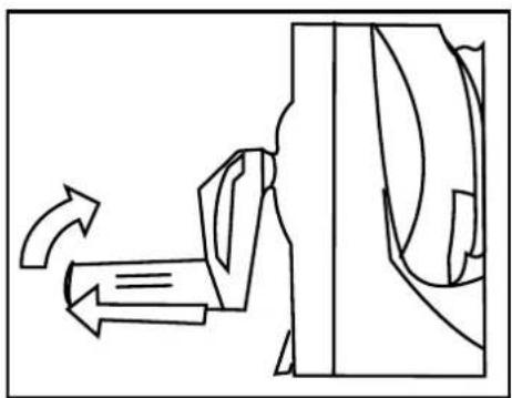
2.5.7 HOSE-REEL HANDLE
The hose reel handle turns down for use and up for storage. To turn up the handle, pull out and turn up. (fig D)
2.5.8 LONG TERM STORAGE
The machine should be stored in a frost-free environment.
After long-term storage without operation, it is possible to form scales inside the machine making it hard to start again. In such conditions it is recommended to turn off and disconnect the power
supply and rotate the motor by hand several times so as to avoid excessive current draw on the motor and the power supply.
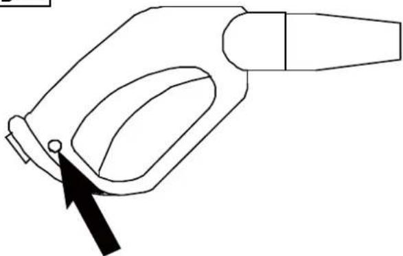
2.5.9 GUN SAFETY DEVICE
Whenever you use the high pressure washer, we suggest you grip the in the right position, with one hand on the handle and the other on the lance. When you stop the machine it is necessary to use the safety lock placed on the gun in order to avoid accidental. (Fig. E)
2.5.10 Cleaning pin instruction
- Using included tip cleaner, or an unfolded paper clip, insert wire into the nozzle hole and move back and forth until debris is dislodged. (Fig. F)
- Remove additional debris by back-flushing water through the nozzle. To do this, place end of a garden hose (with water running) to the end of nozzle for 30-60 seconds.
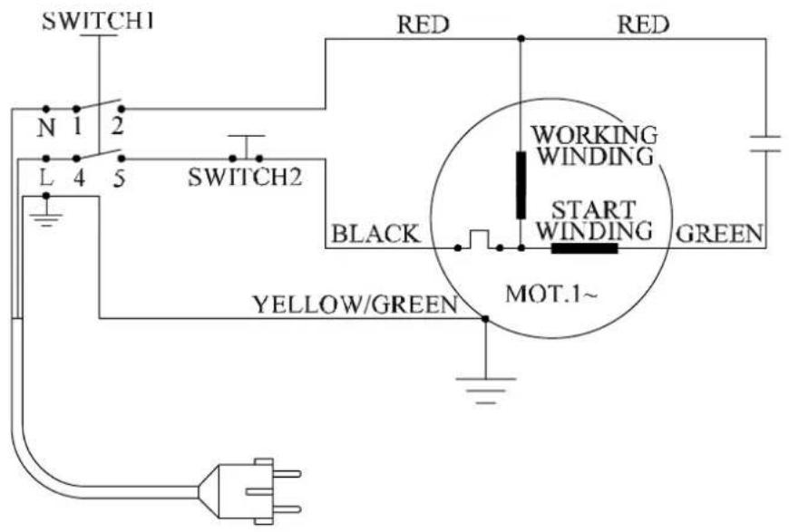
2.6 ELECTRICAL DIAGRAM
text_image
SWITCH1 N 1 2 L 4 5 SWITCH2 RED RED WORKING WINDING START WINDING GREEN BLACK MOT.1~ YELLOW/GREEN -2.7 INSPECTION & MAINTENANCE
For safety use, make sure a three-month clean the machine. Before working, make sure inspect the filter and the nozzle, make sure there is no impurity. After working, make sure there is no water in the pump and the hose.
If the machine need to be repaired in the guarantee period, please return the machine to the shop. You need to provide the certificate of purchase in order to repair or get the substitute.
Before Packaging, the machine should be cleaned, then use closed packaging, packaging should be firm. Storage the machine in dry.
For transportation safety. The machine should comply with ISTA.
2.7.1 INSTALLATION, ELECTRICAL AND WATER CONNECTIONS
| 1 | PRESSURE CLEANER | 5 | HIGH PRESSURE TUBE |
| 2 | WATER SUPPLY HOSE(not include) | 6 | HIGH-PRESSURE, WATER OUTLET |
| 3 | WATER CONNECTION | 7 | SPRAY GUN |
| 4 | WATER INLET | 8 | POWER SUPPLY |
2.7.2 Disposal
DO NOT dispose your ZI-HDR200 / ZI-HDR230 in the residual waste! Contact your local authorities for information about best available disposal possibilities in your area. Drain fuel from the fuel tank completely before disposing the machine. Disaggregate the compactor into its components before disposing its components.

text_image
ne2.8 Spare part order
With original ZIPPER spare parts you use parts that are attuned to each other and short-en the installation time and elongate your machines lifespan.
AT TE NT ION
The installation of non-original parts renders warranty null and void. Exempted is the replacement of the spark plug if carried out by a specialist.
You find the order address in the preface of this operation manual.
2.9 Possible problem and solution
| FAULT | PROBABLE CAUSE | REPAIR |
| When switched on the machine will not start working | Plug is not well connected or electric socket is faultyThe main voltage is insufficient, lower than minimum requirementThe pump is stuck.Thermal safety switch has tripped | Check plug, socketCheck that the main voltage is adequate.Switch off the unit and let the motor cool for a few minutesLeave the lance open |
| Fluctuating Pressure | Pump sucking air.Valves dirty, worn out or stuck.Pump seals worn out. | Check that hoses and connections are airtight.Clean and replace, or refer to dealer.. |
| Water leaking from the pump. | Seals worn out. | Check and replace, or refer to dealer. |
| The motor stops suddenly. | Thermal safety switch has tripped due to overheating. | Check that the main voltage corresponds to specifications.Switch off the unit and let it cool for a few minutes. |
| The pump doesn't reach the necessary pressure. | Water inlet filter is clogged.Pump sucking air from connections or hoses.Suction/ delivery valves are clogged or worn out.Unloaded valve is stuck.Lance nozzle incorrect or worn out. | Clean the water inlet filter.Check that all supply connections are tightCheck that the water feeding hose is not leaking.Clear or replace valves.Loosen and re-tighten regulation screw.Check and/or replace |
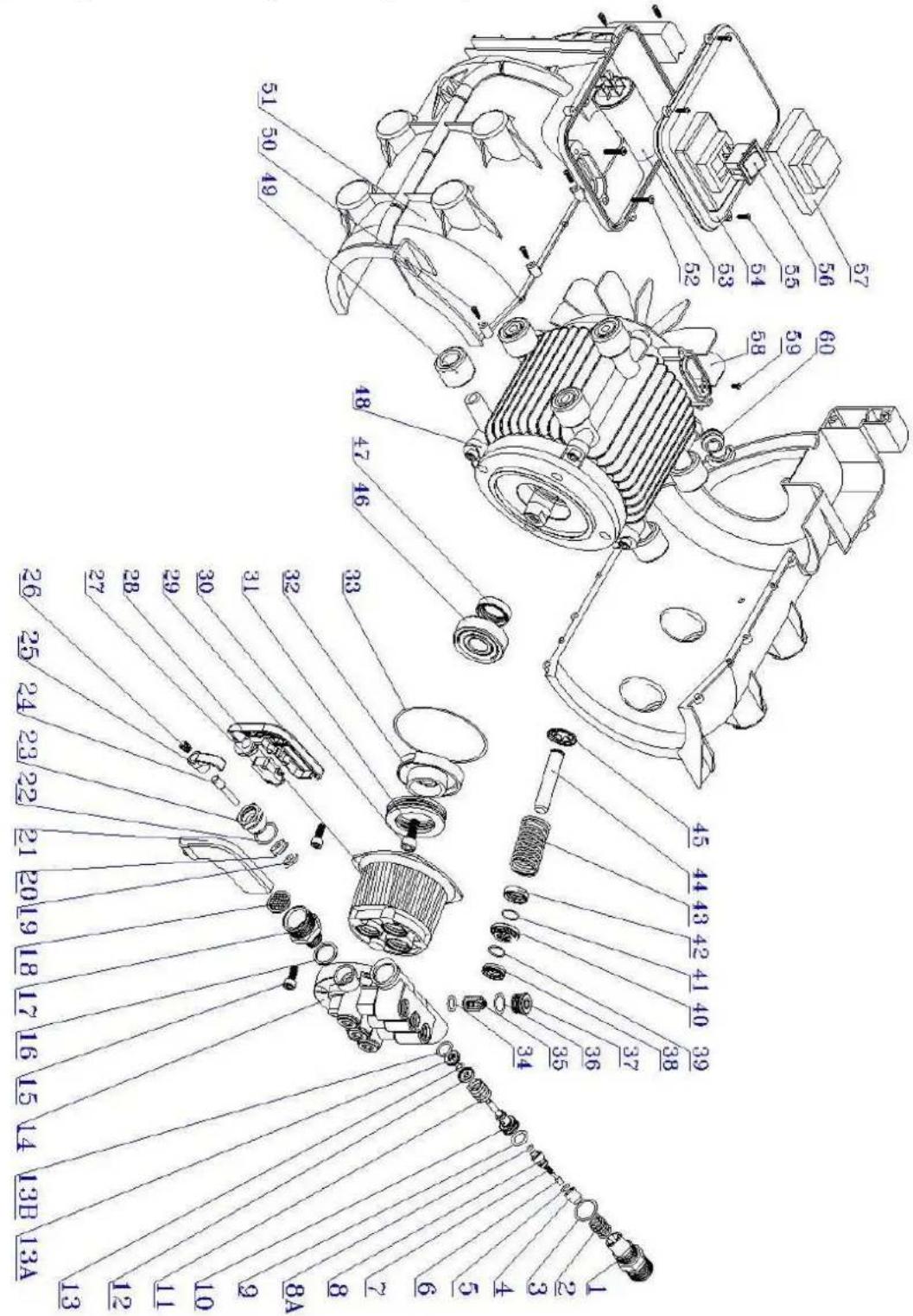
2.10 Spare part drawings and spare part lists
text_image
Technical diagram of a mechanical assembly with numbered parts, likely an engine or motor assembly.| Pos. | Name | Pcs. |
| 1 | Kit, water outlet joint | 1 |
| 2 | O-ring 22x2 4mm | 1 |
| 3 | Spring 6x10.5x4.5x12 | 1 |
| 4 | Cap, valve | 1 |
| 5 | O-ring, 5x1.8mm | 1 |
| 6 | Valve | 1 |
| 7 | Spring valve | 1 |
| 8 | Cover, valve | 1 |
| 8A | O-ring, 4.5x.1.8mm | 1 |
| 9 | O-ring, 16x2.4mm | 1 |
| 10 | Piston | 1 |
| 11 | Piston spring | 1 |
| 12 | Spring seat | 1 |
| 13 | O-ring, 5x1.8mm | 1 |
| 13A | Seat, valve | 1 |
| 13B | O-ring, 12x1.8mm | 1 |
| 14 | Pump head | 1 |
| 15 | Screw M8x20 | 4 |
| 16 | O-ringx 18x2.4mm | 1 |
| 17 | Inlet connector | 1 |
| 18 | Filter | 1 |
| 19 | Connection block circlip | 1 |
| 20 | Y-ring | 1 |
| 21 | Switch cover | 1 |
| 22 | O-ring, 22x2.4mm | 1 |
| 23 | Connection block | 1 |
| 24 | Switch mandril | 1 |
| 25 | Elbow | 1 |
| 26 | Spring, 1x7.8x 9x19 | 1 |
| 27 | Microswitch | 1 |
| 28 | Pump body | 1 |
| 29 | Down cover, pressure switch | 1 |
| Pos. | Name | Pcs. |
| 30 | Screw internal, hexagonal M8x25 | 1 |
| 31 | Bearing, 51207 | 1 |
| 32 | Bearing housing | 1 |
| 33 | O-ring 90x2.65 | 1 |
| 34 | O-ring, 14x1.9 | 6 |
| 35 | Inlet&outlet valve | 6 |
| 36 | O-ring 16x1.9 | 6 |
| 37 | Valve cap | 6 |
| 38 | V-ring 14x24x5mm | 3 |
| 39 | O-ring 18x1.9 | 3 |
| 40 | Interspace ringer | 3 |
| 41 | O-ring 26x | 3 |
| 42 | Reinforced seal 14x24x5mm | 3 |
| 43 | Spring | 3 |
| 44 | Plunger 14 | 3 |
| 45 | Plunger clip | 3 |
| 46 | Bearing | 1 |
| 47 | Oil seal | 1 |
| 48 | Induction motor | 1 |
| 49 | Motor cover | 1 |
| 50 | Self-tapping screw | 1 |
| 51 | Motor enclosure | 1 |
| 52 | Self-tapping screw | 4 |
| 53 | Capacitor | 1 |
| 54 | Junctionbox | 1 |
| 55 | Self-tapping screw | 4 |
| 56 | Switch | 1 |
| 57 | Switch cover | 1 |
| 58 | Fan | 1 |
| 59 | Round head screw | 2 |
| 60 | Cable sheat | 1 |
D/EN
KONFORMITÄTSERKLÄRUNG / DECLARATION OF CONFORMITY

Z.I.P.P.E.R ^® AUSTRIA GmbH
Gewerbepark 8
AT-4707 Schlüsslberg
Tel.: +43/72480/61116-700; Fax.: +43/7248/61116-720
www.zipper-maschinen.at
info@zipper-maschinen.at
The above mentioned machine complies with all relevant requirements of the above stated directives. Any manipulation of the machine not explicitly approved by us renders this document null and void.
Schlüsslberg, 12.03.2010
Ort, Datum/city, date